Cambridge A Level Physics 9702 — 2020 Feb/March Paper 4 · Variant 2
9702/42/F/M/20 · 12 questions · 100 marks · ≈113 min
The question paper and its mark scheme, free to read here and free to download. This is Cambridge’s own paper, exactly as it was sat.
Question paper28 pages



Mark scheme19 pages
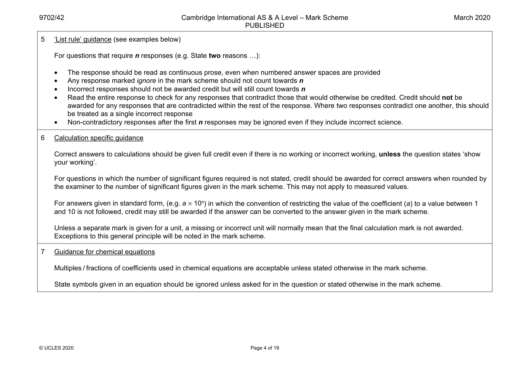
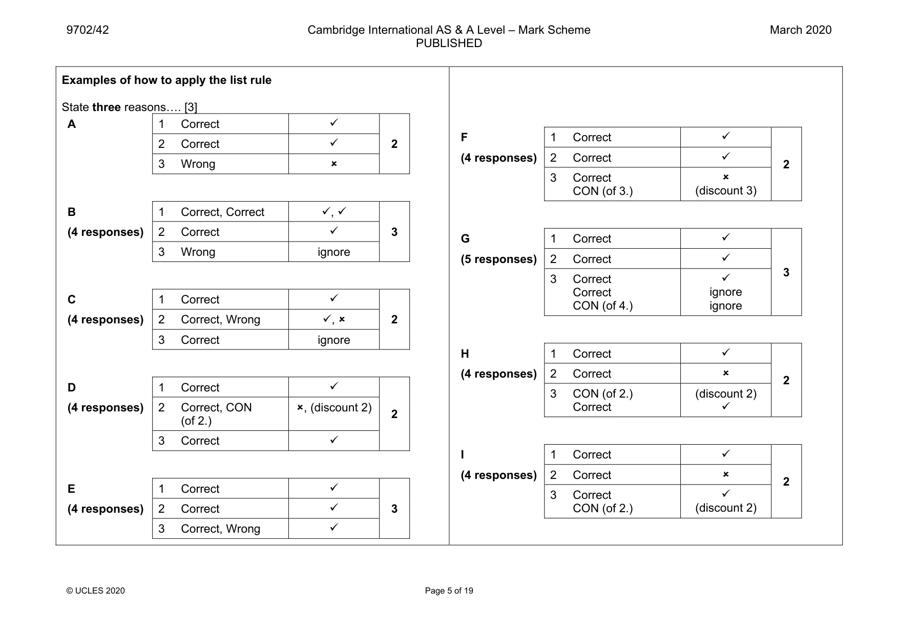
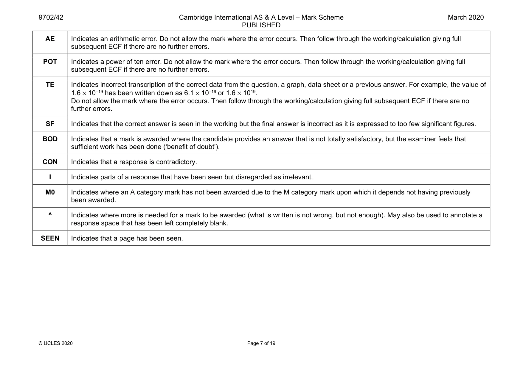
Answers below. Sit the paper first if you are practising.

Questions as text
Q1 · Define gravitational potential at a point
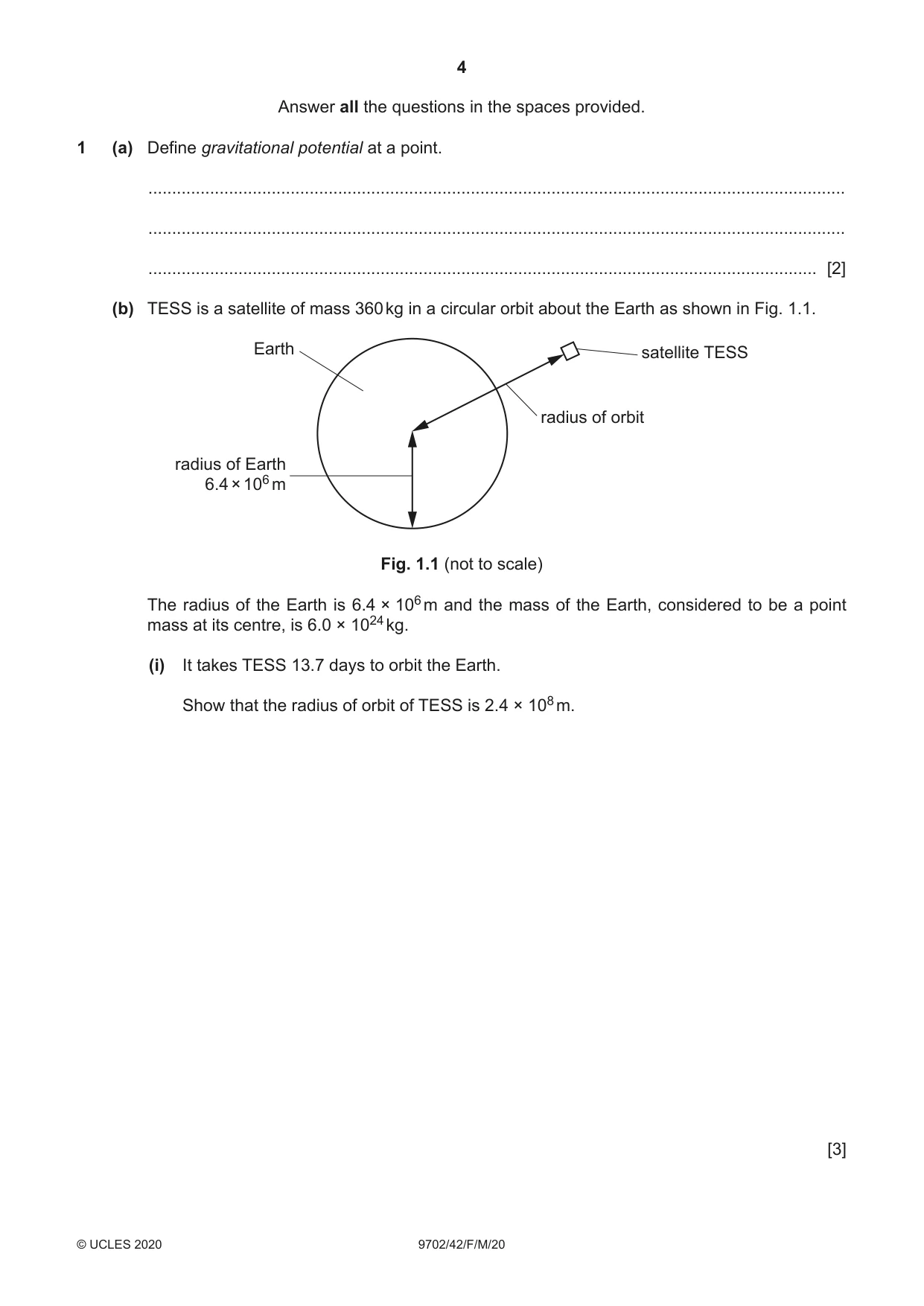
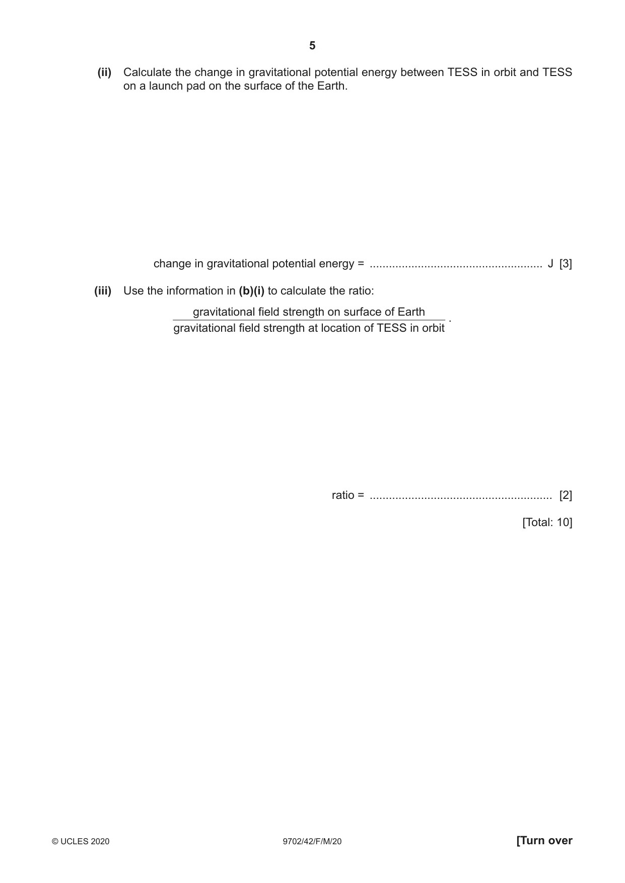
1 (a) Define gravitational potential at a point. ................................................................................................................................................... ................................................................................................................................................... ............................................................................................................................................. [2] (b) TESS is a satellite of mass 360 kg in a circular orbit about the Earth as shown in Fig. 1.1. Earth satellite TESS radius of orbit radius of Earth 6.4 × 10⁶ m Fig. 1.1 (not to scale) The radius of the Earth is 6.4 × 10⁶ m and the mass of the Earth, considered to be a point mass at its centre, is 6.0 × 1024 kg. (i) It takes TESS 13.7 days to orbit the Earth. Show that the radius of orbit of TESS is 2.4 × 10⁸ m. [3] (ii) Calculate the change in gravitational potential energy between TESS in orbit and TESS on a launch pad on the surface of the Earth. change in gravitational potential energy = ...................................................... J [3] (iii) Use the information in (b)(i) to calculate the ratio: gravitational field strength on surface of Earth . gravitational field strength at location of TESS in orbit ratio = ......................................................... [2] [Total: 10]
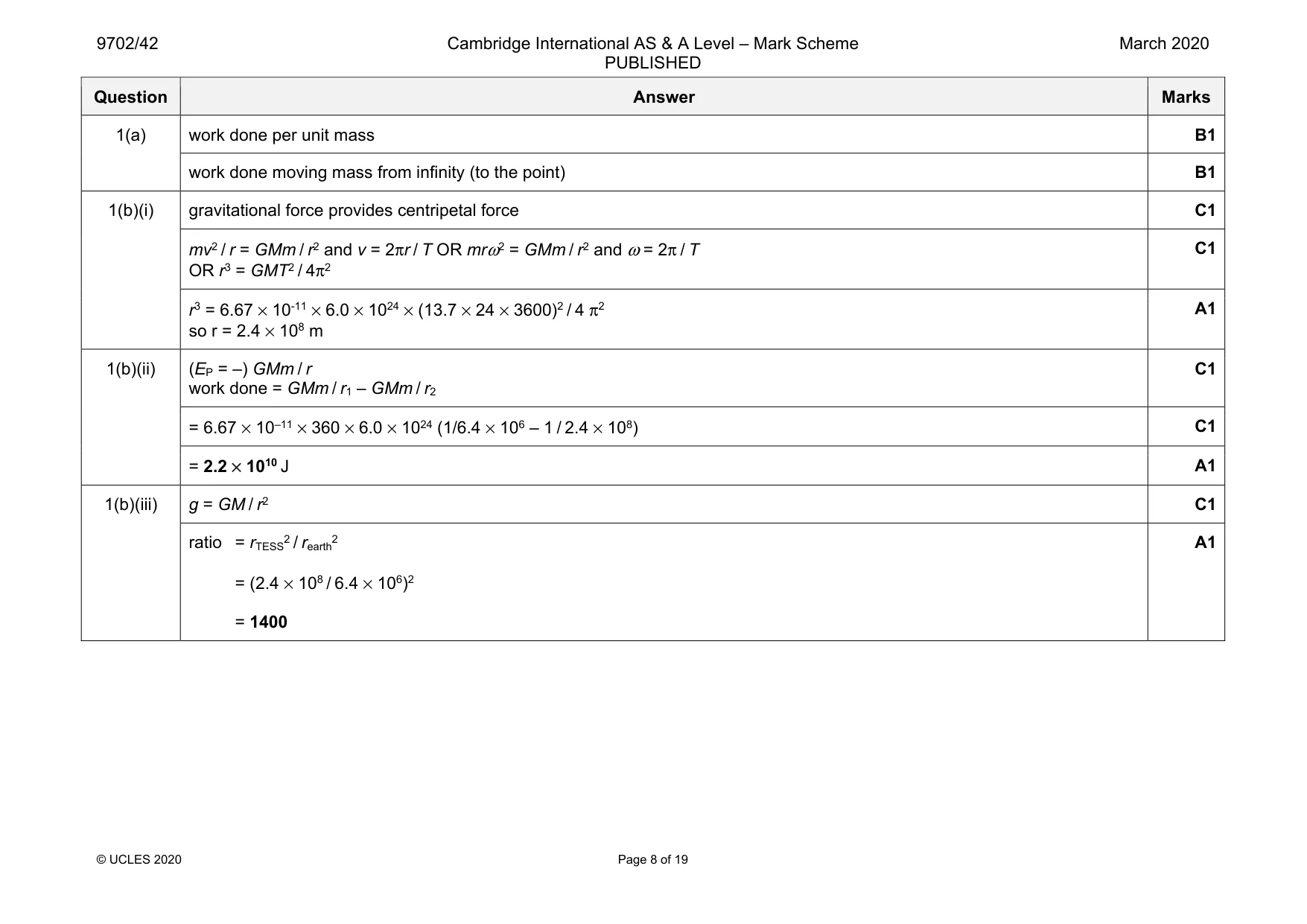
Mark scheme: 1(a) work done per unit mass B1 work done moving mass from infinity (to the point) B1 1(b)(i) gravitational force provides centripetal force C1 mv2 / r = GMm / r2 and v = 2πr / T OR mrω2 = GMm / r2 and ω = 2π / T OR r3 = GMT2 / 4π2 C1 r3 = 6.67 × 10-11 × 6.0 × 1024 × (13.7 × 24 × 3600)2 / 4 π2 so r = 2.4 × 10⁸ m A1 1(b)(ii) (EP = –) GMm / r work done = GMm / r1 – GMm / r2 C1 = 6.67 × 10–11 × 360 × 6.0 × 1024 (1/6.4 × 106 – 1 / 2.4 × 10⁸) C1 = 2.2 × 10¹⁰ J A1 1(b)(iii) g = GM / r2 C1 ratio = rTESS2 / rearth2 = (2.4 × 10⁸ / 6.4 × 10⁶)2 = 1400 A1
Q2 · A large container of volume 85 m3 is filled with 110 kg of an ideal gas
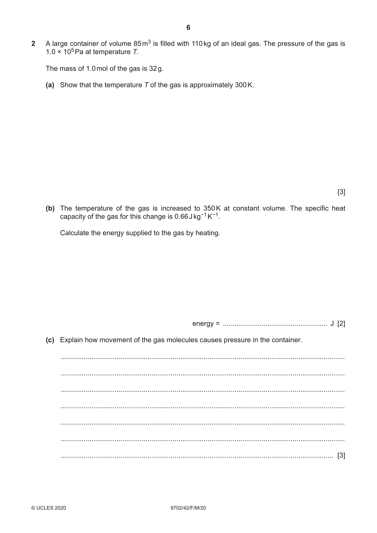
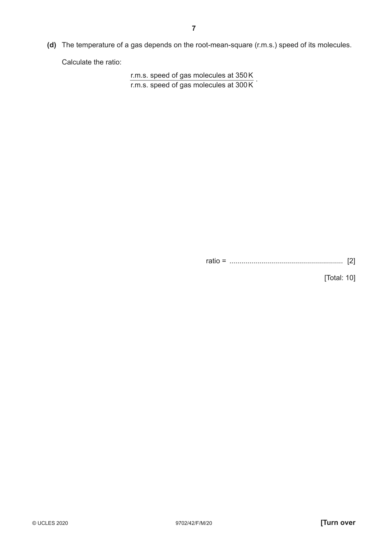
2 A large container of volume 85 m3 is filled with 110 kg of an ideal gas. The pressure of the gas is 1.0 × 10⁵ Pa at temperature T. The mass of 1.0 mol of the gas is 32 g. (a) Show that the temperature T of the gas is approximately 300 K. [3] (b) The temperature of the gas is increased to 350 K at constant volume. The specific heat capacity of the gas for this change is 0.66 J kg−1 K−1. Calculate the energy supplied to the gas by heating. energy = ...................................................... J [2] (c) Explain how movement of the gas molecules causes pressure in the container. ................................................................................................................................................... ................................................................................................................................................... ................................................................................................................................................... ................................................................................................................................................... ................................................................................................................................................... ................................................................................................................................................... ............................................................................................................................................. [3] (d) The temperature of a gas depends on the root-mean-square (r.m.s.) speed of its molecules. Calculate the ratio: r.m.s. speed of gas molecules at 350 K . r.m.s. speed of gas molecules at 300 K ratio = ......................................................... [2] [Total: 10]
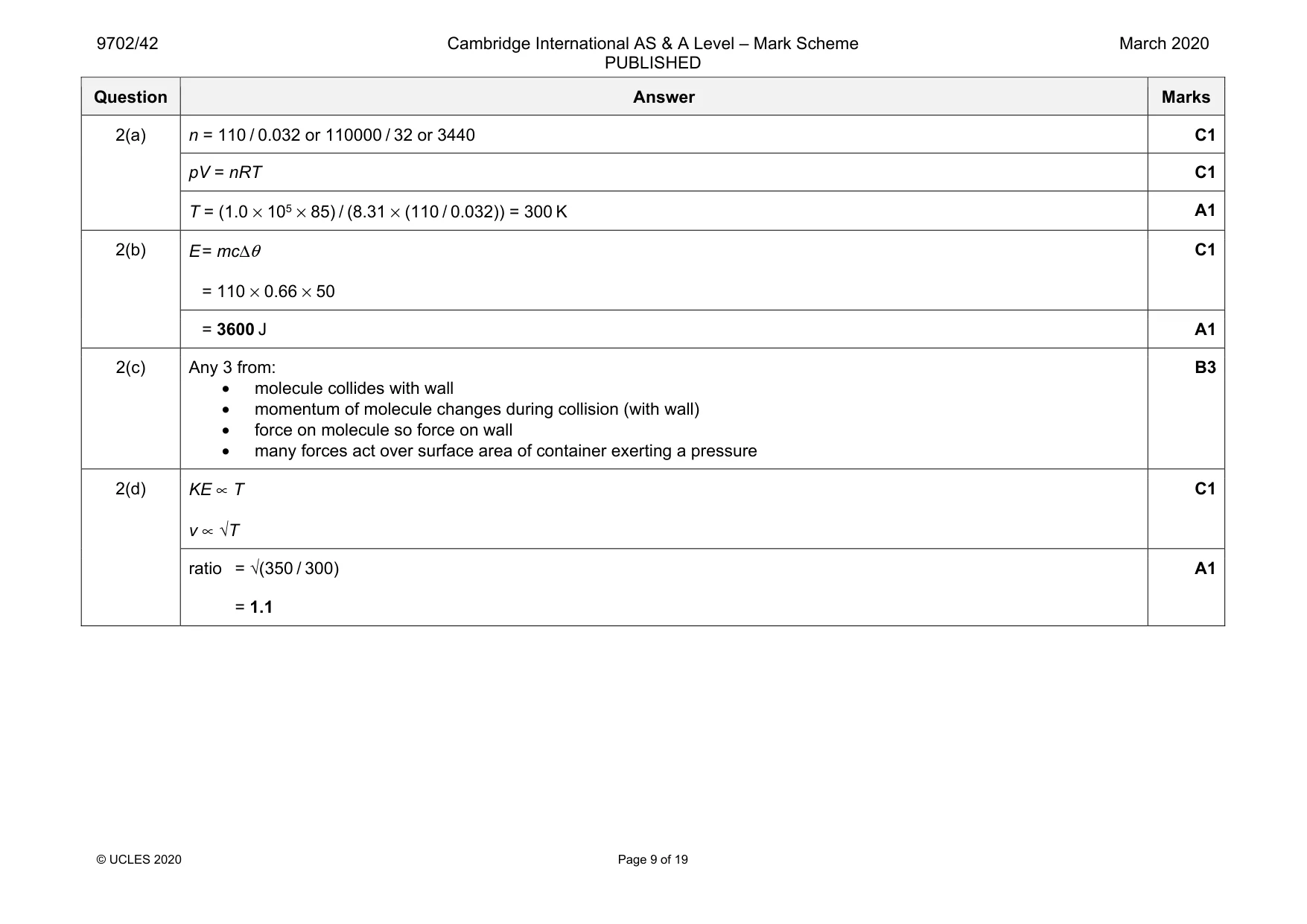
Mark scheme: 2(a) n = 110 / 0.032 or 110000 / 32 or 3440 C1 pV = nRT C1 T = (1.0 × 105 × 85) / (8.31 × (110 / 0.032)) = 300 K A1 2(b) E = mcΔθ = 110 × 0.66 × 50 C1 = 3600 J A1 2(c) Any 3 from: • molecule collides with wall • momentum of molecule changes during collision (with wall) • force on molecule so force on wall • many forces act over surface area of container exerting a pressure B3 2(d) KE ∝ T v ∝ √T C1 ratio = √(350 / 300) = 1.1 A1
Q3 · A body undergoes simple harmonic motion
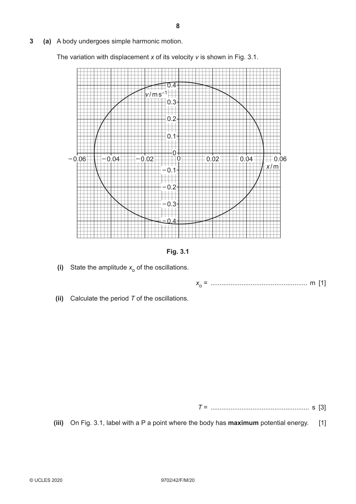
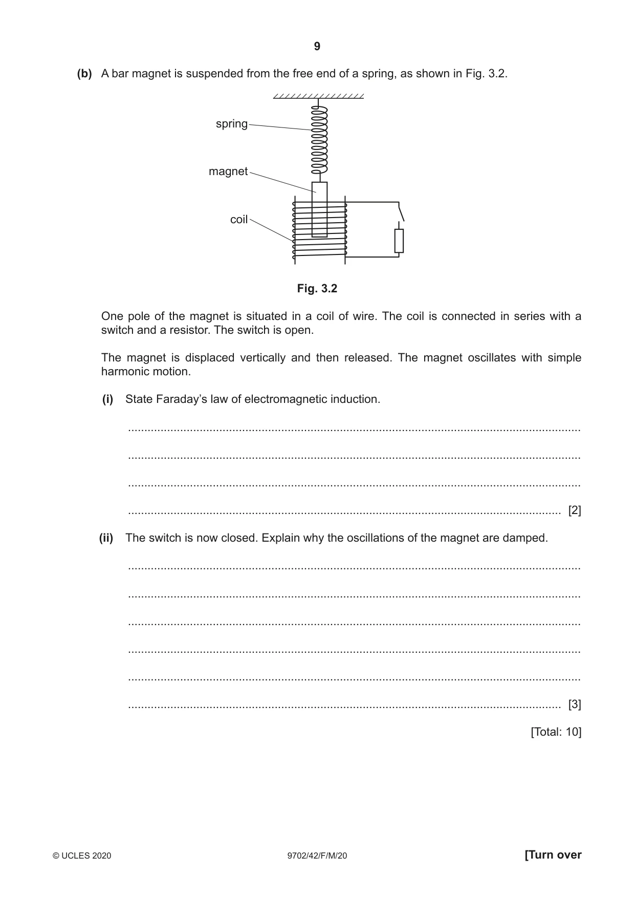
3 (a) A body undergoes simple harmonic motion. The variation with displacement x of its velocity v is shown in Fig. 3.1. 0.4 v / m s–1 0.3 0.2 0.1 0 – 0.06 – 0.04 – 0.02 0 0.02 0.04 0.06 x / m – 0.1 – 0.2 – 0.3 – 0.4 Fig. 3.1 (i) State the amplitude xo of the oscillations. xo = ..................................................... m [1] (ii) Calculate the period T of the oscillations. T = ...................................................... s [3] (iii) On Fig. 3.1, label with a P a point where the body has maximum potential energy. [1] (b) A bar magnet is suspended from the free end of a spring, as shown in Fig. 3.2. spring magnet coil Fig. 3.2 One pole of the magnet is situated in a coil of wire. The coil is connected in series with a switch and a resistor. The switch is open. The magnet is displaced vertically and then released. The magnet oscillates with simple harmonic motion. (i) State Faraday’s law of electromagnetic induction. ........................................................................................................................................... ........................................................................................................................................... ........................................................................................................................................... ..................................................................................................................................... [2] (ii) The switch is now closed. Explain why the oscillations of the magnet are damped. ........................................................................................................................................... ........................................................................................................................................... ........................................................................................................................................... ........................................................................................................................................... ........................................................................................................................................... ..................................................................................................................................... [3] [Total: 10]
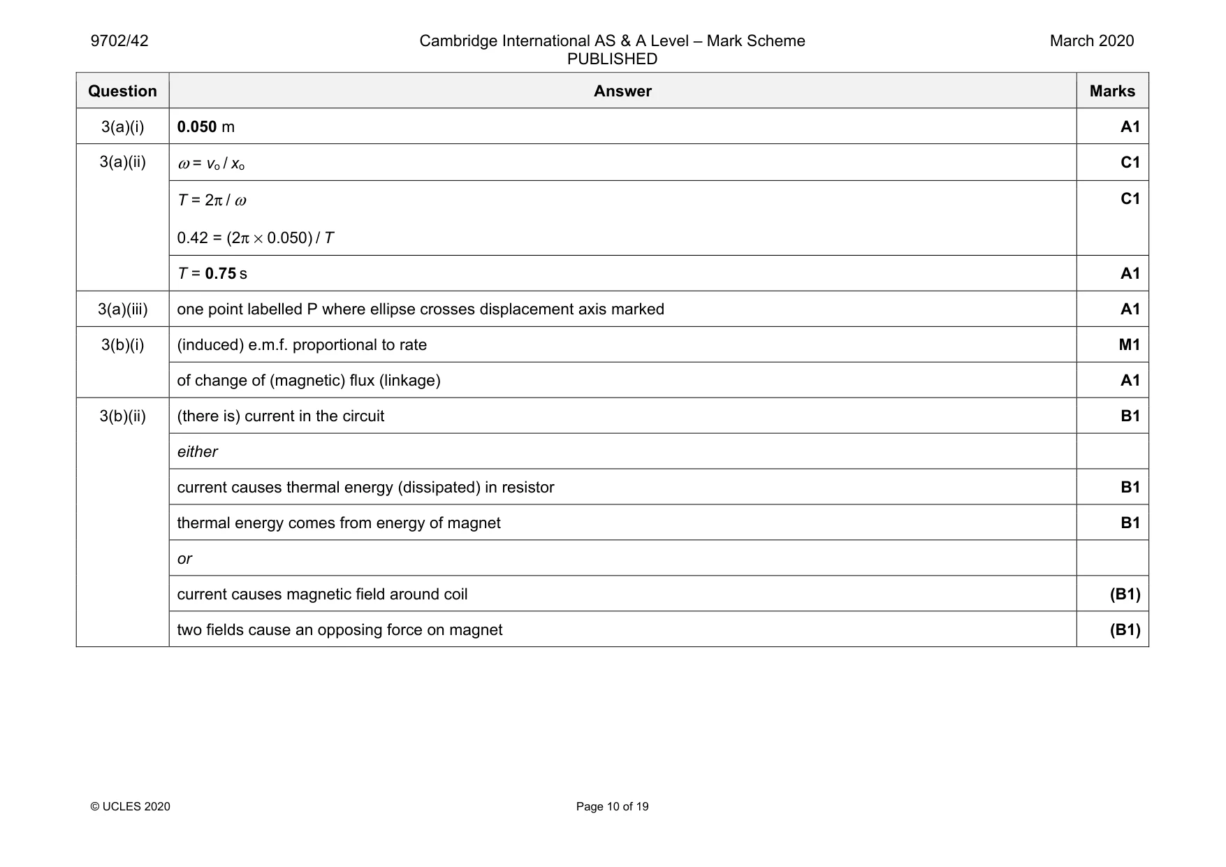
Mark scheme: 3(a)(i) 0.050 m A1 3(a)(ii) ω = vo / xo C1 T = 2π / ω 0.42 = (2π × 0.050) / T C1 T = 0.75 s A1 3(a)(iii) one point labelled P where ellipse crosses displacement axis marked A1 3(b)(i) (induced) e.m.f. proportional to rate M1 of change of (magnetic) flux (linkage) A1 3(b)(ii) (there is) current in the circuit B1 either current causes thermal energy (dissipated) in resistor B1 thermal energy comes from energy of magnet B1 or current causes magnetic field around coil (B1) two fields cause an opposing force on magnet (B1)
Q4 · Explain why ultrasound used in medical diagnosis is emitted in pulses
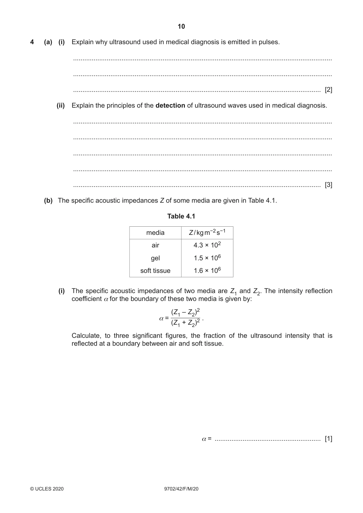
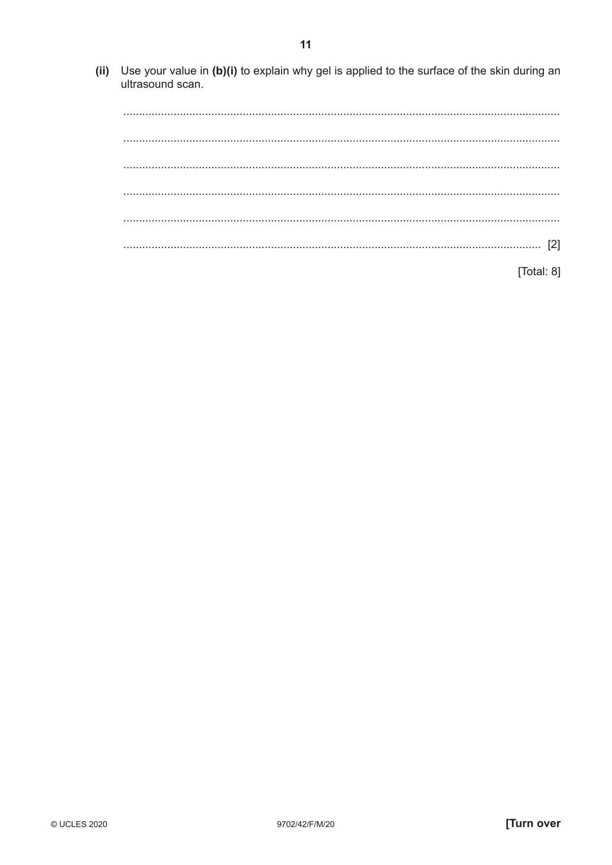
4 (a) (i) Explain why ultrasound used in medical diagnosis is emitted in pulses. ........................................................................................................................................... ........................................................................................................................................... ..................................................................................................................................... [2] (ii) Explain the principles of the detection of ultrasound waves used in medical diagnosis. ........................................................................................................................................... ........................................................................................................................................... ........................................................................................................................................... ........................................................................................................................................... ..................................................................................................................................... [3] (b) The specific acoustic impedances Z of some media are given in Table 4.1. Table 4.1 media Z / kg m−2 s−1 air 4.3 × 10² gel 1.5 × 10⁶ soft tissue 1.6 × 10⁶ (i) The specific acoustic impedances of two media are Z1 and Z2. The intensity reflection coefficient α for the boundary of these two media is given by: (Z1 – Z2)2 α = . (Z1 + Z2)2 Calculate, to three significant figures, the fraction of the ultrasound intensity that is reflected at a boundary between air and soft tissue. α = ......................................................... [1] (ii) Use your value in (b)(i) to explain why gel is applied to the surface of the skin during an ultrasound scan. ........................................................................................................................................... ........................................................................................................................................... ........................................................................................................................................... ........................................................................................................................................... ........................................................................................................................................... ..................................................................................................................................... [2] [Total: 8]
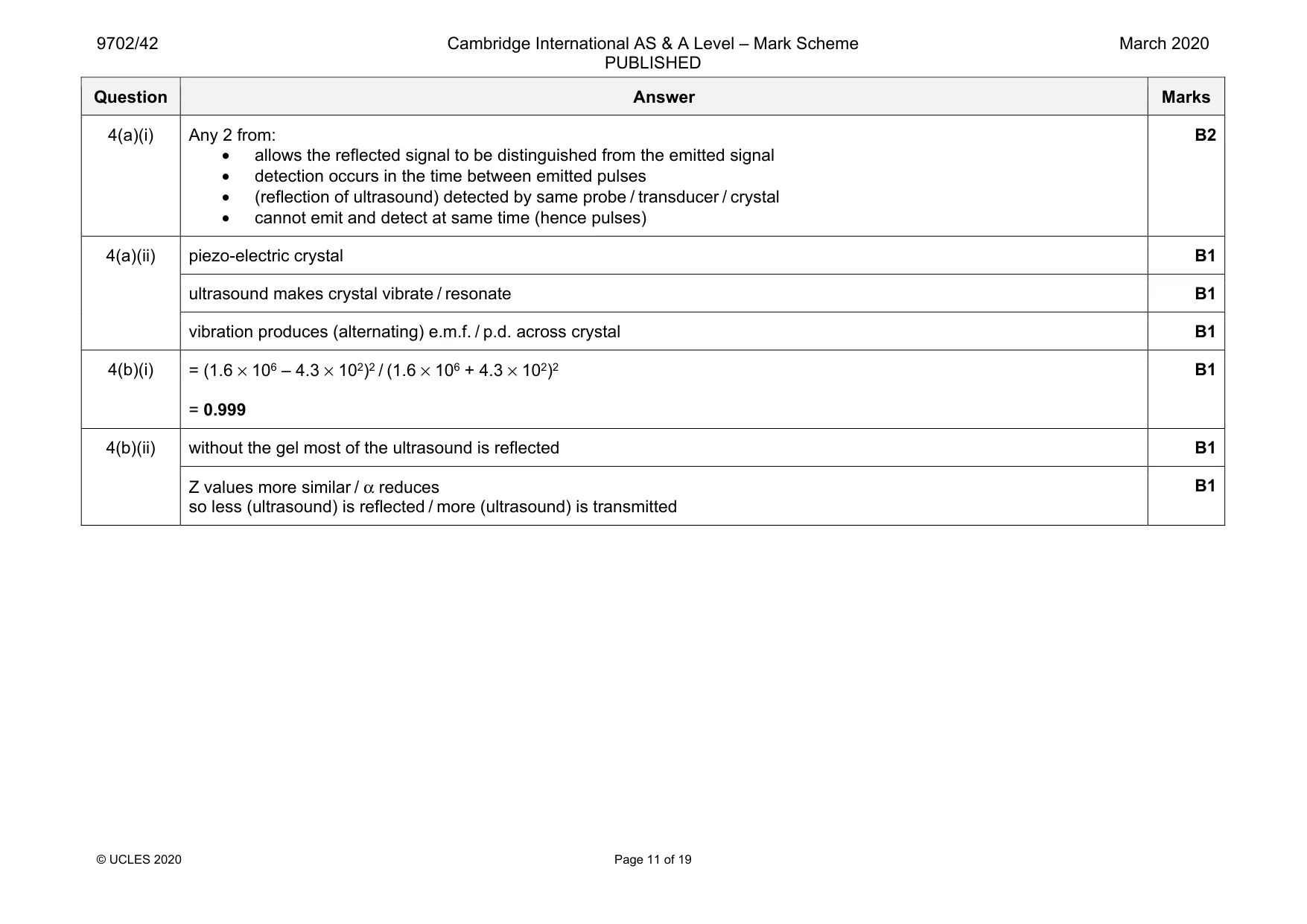
Mark scheme: 4(a)(i) Any 2 from: • allows the reflected signal to be distinguished from the emitted signal • detection occurs in the time between emitted pulses • (reflection of ultrasound) detected by same probe / transducer / crystal • cannot emit and detect at same time (hence pulses) B2 4(a)(ii) piezo-electric crystal B1 ultrasound makes crystal vibrate / resonate B1 vibration produces (alternating) e.m.f. / p.d. across crystal B1 4(b)(i) = (1.6 × 10⁶ – 4.3 × 10²)2 / (1.6 × 10⁶ + 4.3 × 10²)2 = 0.999 B1 4(b)(ii) without the gel most of the ultrasound is reflected B1 Z values more similar / α reduces so less (ultrasound) is reflected / more (ultrasound) is transmitted B1
Q5 · State two advantages of the transmission of data in digital form, rather than analogue…
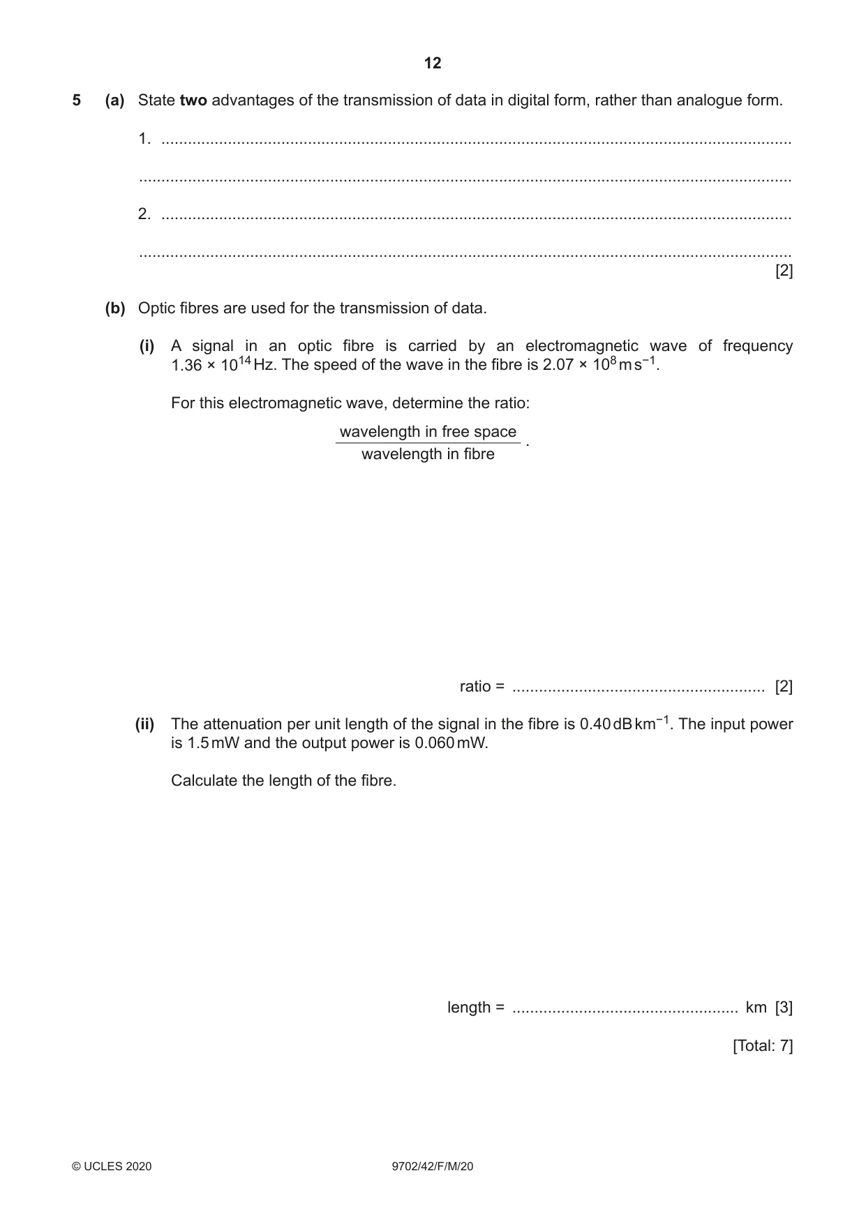
5 (a) State two advantages of the transmission of data in digital form, rather than analogue form. 1. .............................................................................................................................................. ................................................................................................................................................... 2. .............................................................................................................................................. ................................................................................................................................................... [2] (b) Optic fibres are used for the transmission of data. (i) A signal in an optic fibre is carried by an electromagnetic wave of frequency 1.36 × 10¹⁴ Hz. The speed of the wave in the fibre is 2.07 × 10⁸ m s−1. For this electromagnetic wave, determine the ratio: wavelength in free space . wavelength in fibre ratio = ......................................................... [2] (ii) The attenuation per unit length of the signal in the fibre is 0.40 dB km−1. The input power is 1.5 mW and the output power is 0.060 mW. Calculate the length of the fibre. length = ................................................... km [3] [Total: 7]
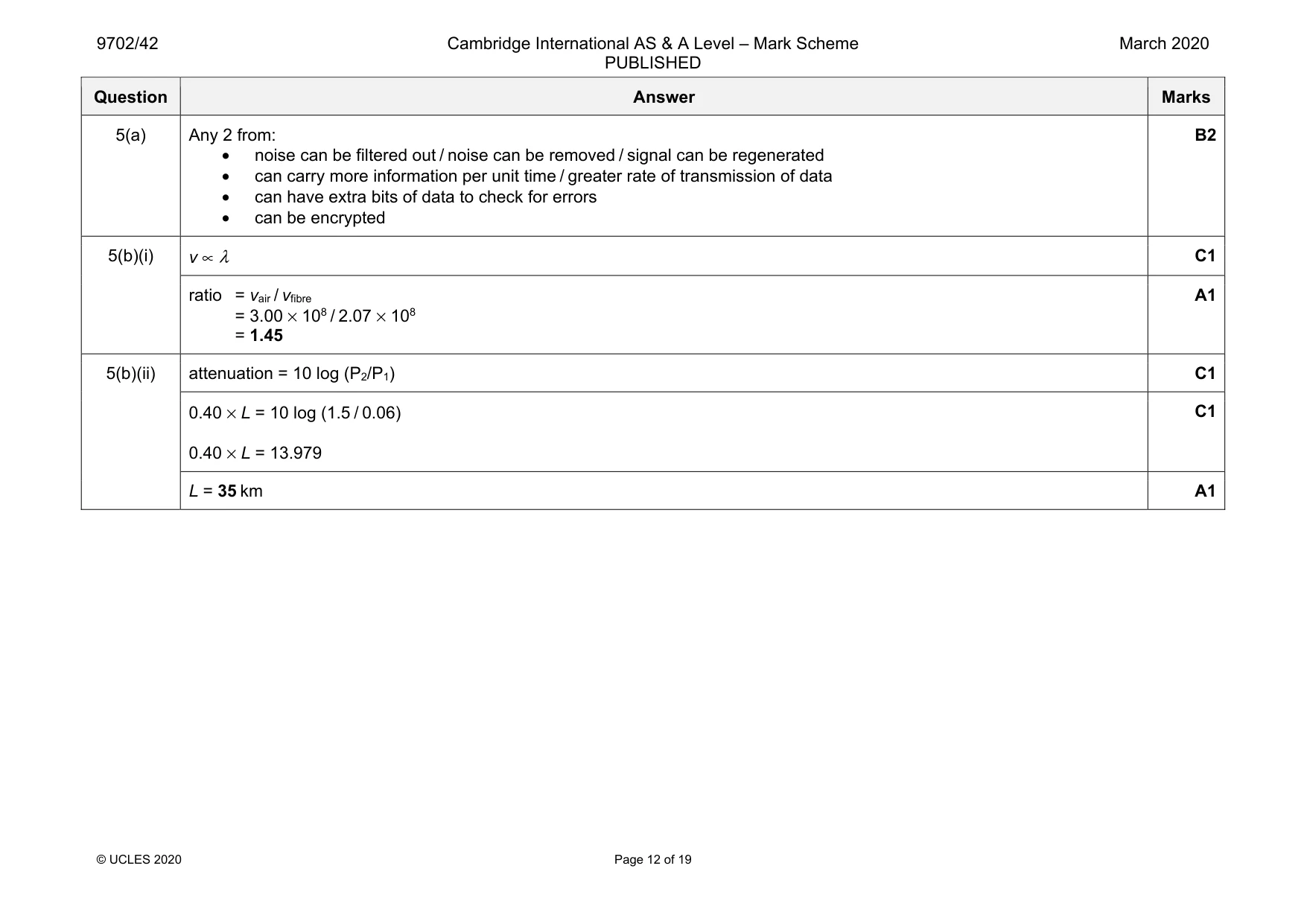
Mark scheme: 5(a) Any 2 from: • noise can be filtered out / noise can be removed / signal can be regenerated • can carry more information per unit time / greater rate of transmission of data • can have extra bits of data to check for errors • can be encrypted B2 5(b)(i) v ∝ λ C1 ratio = vair / vfibre = 3.00 × 10⁸ / 2.07 × 108 = 1.45 A1 5(b)(ii) attenuation = 10 log (P2/P1) C1 0.40 × L = 10 log (1.5 / 0.06) 0.40 × L = 13.979 C1 L = 35 km A1
Q6 · Two positively charged identical metal spheres A and B have their centres separated by a…
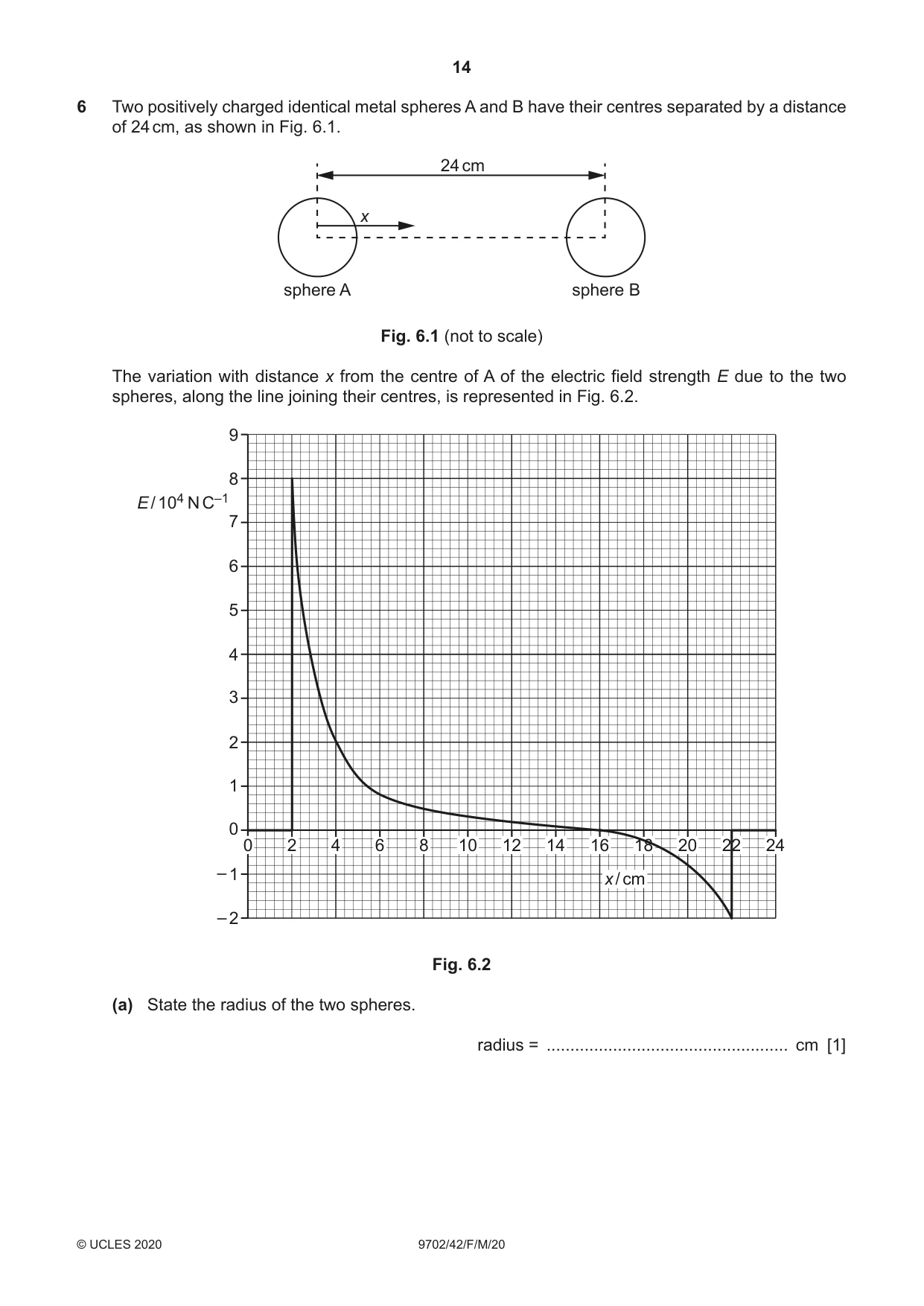
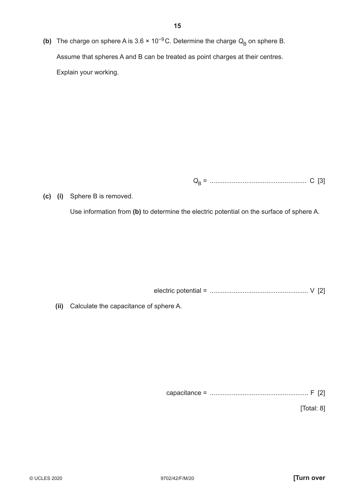
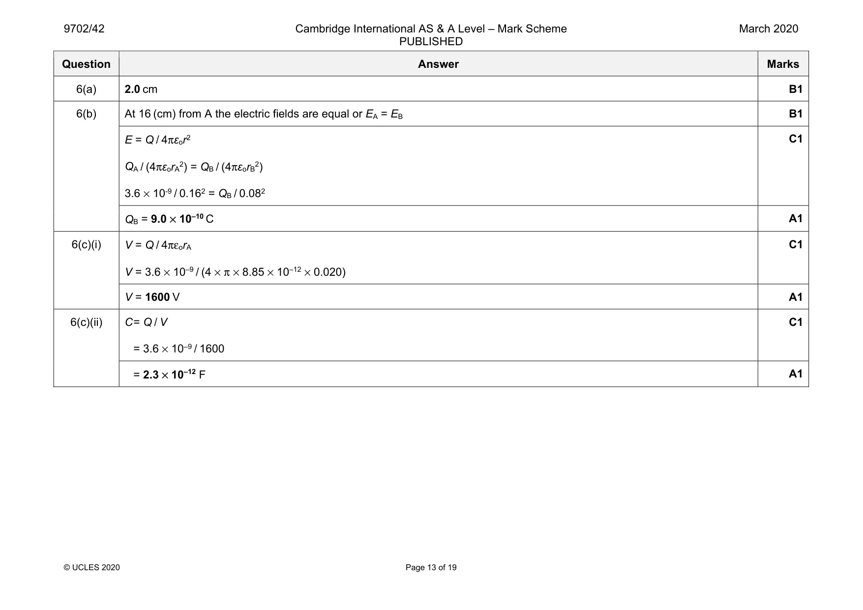
6 Two positively charged identical metal spheres A and B have their centres separated by a distance of 24 cm, as shown in Fig. 6.1. 24 cm x sphere A sphere B Fig. 6.1 (not to scale) The variation with distance x from the centre of A of the electric field strength E due to the two spheres, along the line joining their centres, is represented in Fig. 6.2. 9 8 E / 104 N C–1 7 6 5 4 3 2 1 0 0 2 4 6 8 10 12 14 16 18 20 22 24 – 1 x / cm – 2 Fig. 6.2 (a) State the radius of the two spheres. radius = ................................................... cm [1] (b) The charge on sphere A is 3.6 × 10⁻⁹ C. Determine the charge QB on sphere B. Assume that spheres A and B can be treated as point charges at their centres. Explain your working. QB = ..................................................... C [3] (c) (i) Sphere B is removed. Use information from (b) to determine the electric potential on the surface of sphere A. electric potential = ...................................................... V [2] (ii) Calculate the capacitance of sphere A. capacitance = ...................................................... F [2] [Total: 8]
Mark scheme: 6(a) 2.0 cm B1 6(b) At 16 (cm) from A the electric fields are equal or EA = EB B1 E = Q / 4πεor2 QA / (4πεorA2) = QB / (4πεorB2) 3.6 × 10⁻⁹ / 0.162 = QB / 0.082 C1 QB = 9.0 × 10⁻¹⁰ C A1 6(c)(i) V = Q / 4πεorA V = 3.6 × 10⁻⁹ / (4 × π × 8.85 × 10–12 × 0.020) C1 V = 1600 V A1 6(c)(ii) C = Q / V = 3.6 × 10⁻⁹ / 1600 C1 = 2.3 × 10⁻¹² F A1
Question 7
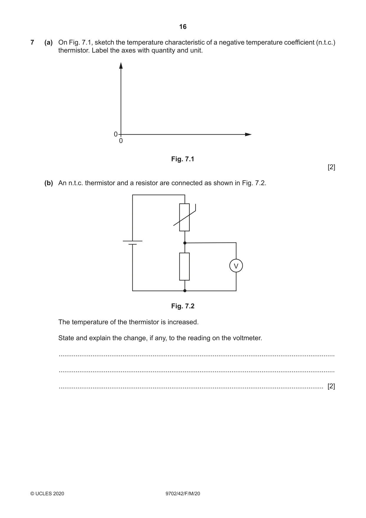
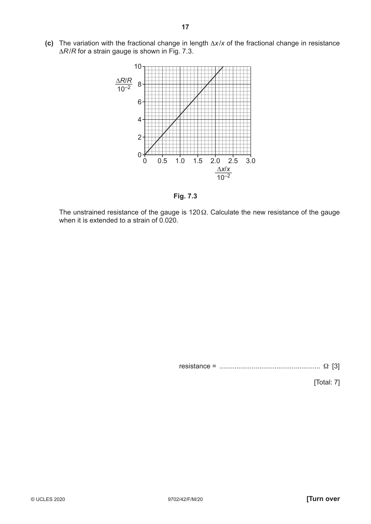
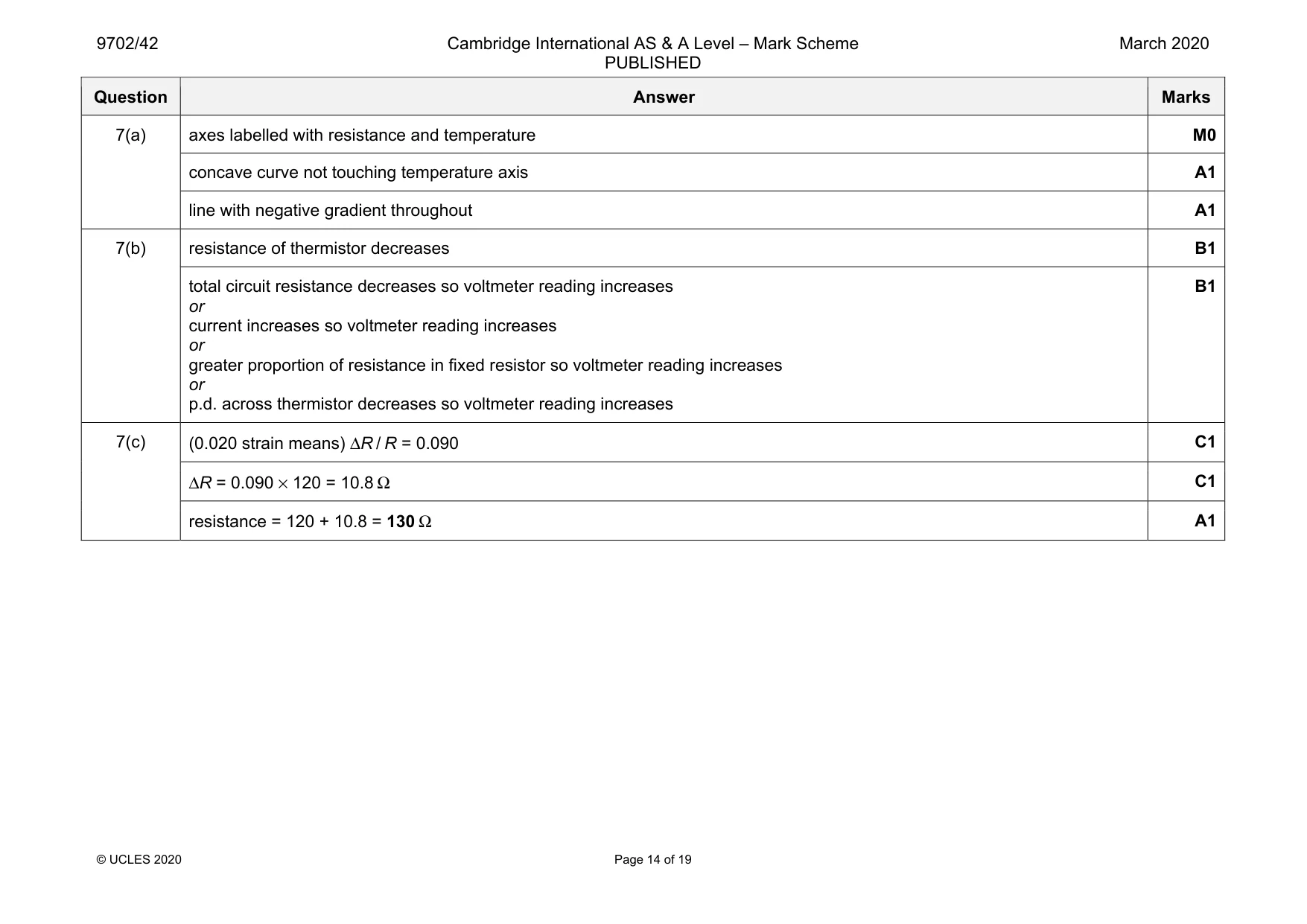
7 (a) On Fig. 7.1, sketch the temperature characteristic of a negative temperature coefficient (n.t.c.) thermistor. Label the axes with quantity and unit. 0 0 Fig. 7.1 [2] (b) An n.t.c. thermistor and a resistor are connected as shown in Fig. 7.2. V Fig. 7.2 The temperature of the thermistor is increased. State and explain the change, if any, to the reading on the voltmeter. ................................................................................................................................................... ................................................................................................................................................... ............................................................................................................................................. [2] (c) The variation with the fractional change in length Δx /x of the fractional change in resistance ΔR /R for a strain gauge is shown in Fig. 7.3. 10 ∆R/R 8 10–2 6 4 2 0 0 0.5 1.0 1.5 2.0 2.5 3.0 ∆x/x 10–2 Fig. 7.3 The unstrained resistance of the gauge is 120 Ω. Calculate the new resistance of the gauge when it is extended to a strain of 0.020. resistance = ..................................................... Ω [3] [Total: 7]
Mark scheme: 7(a) axes labelled with resistance and temperature M0 concave curve not touching temperature axis A1 line with negative gradient throughout A1 7(b) resistance of thermistor decreases B1 total circuit resistance decreases so voltmeter reading increases or current increases so voltmeter reading increases or greater proportion of resistance in fixed resistor so voltmeter reading increases or p.d. across thermistor decreases so voltmeter reading increases B1 7(c) (0.020 strain means) ΔR / R = 0.090 C1 ΔR = 0.090 × 120 = 10.8 Ω C1 resistance = 120 + 10.8 = 130 Ω A1
Q8 · Explain what is meant by a magnetic field
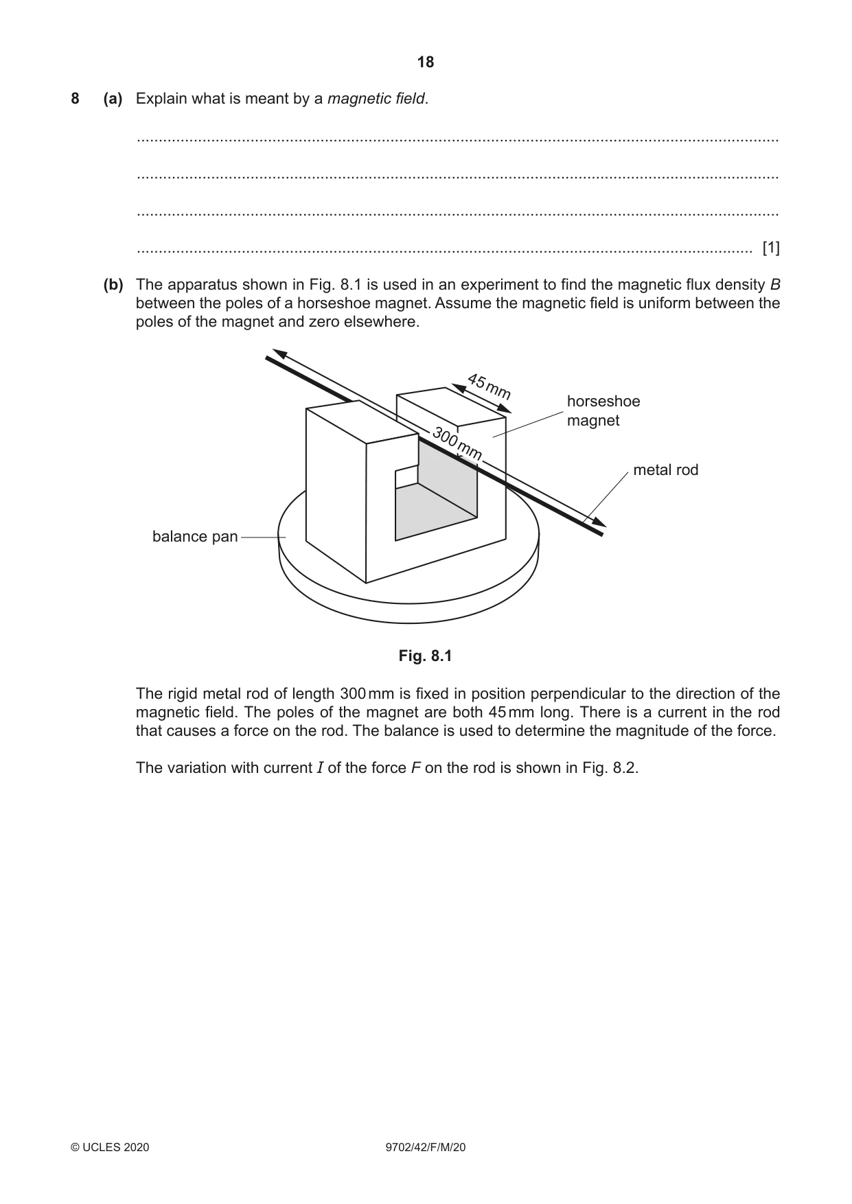
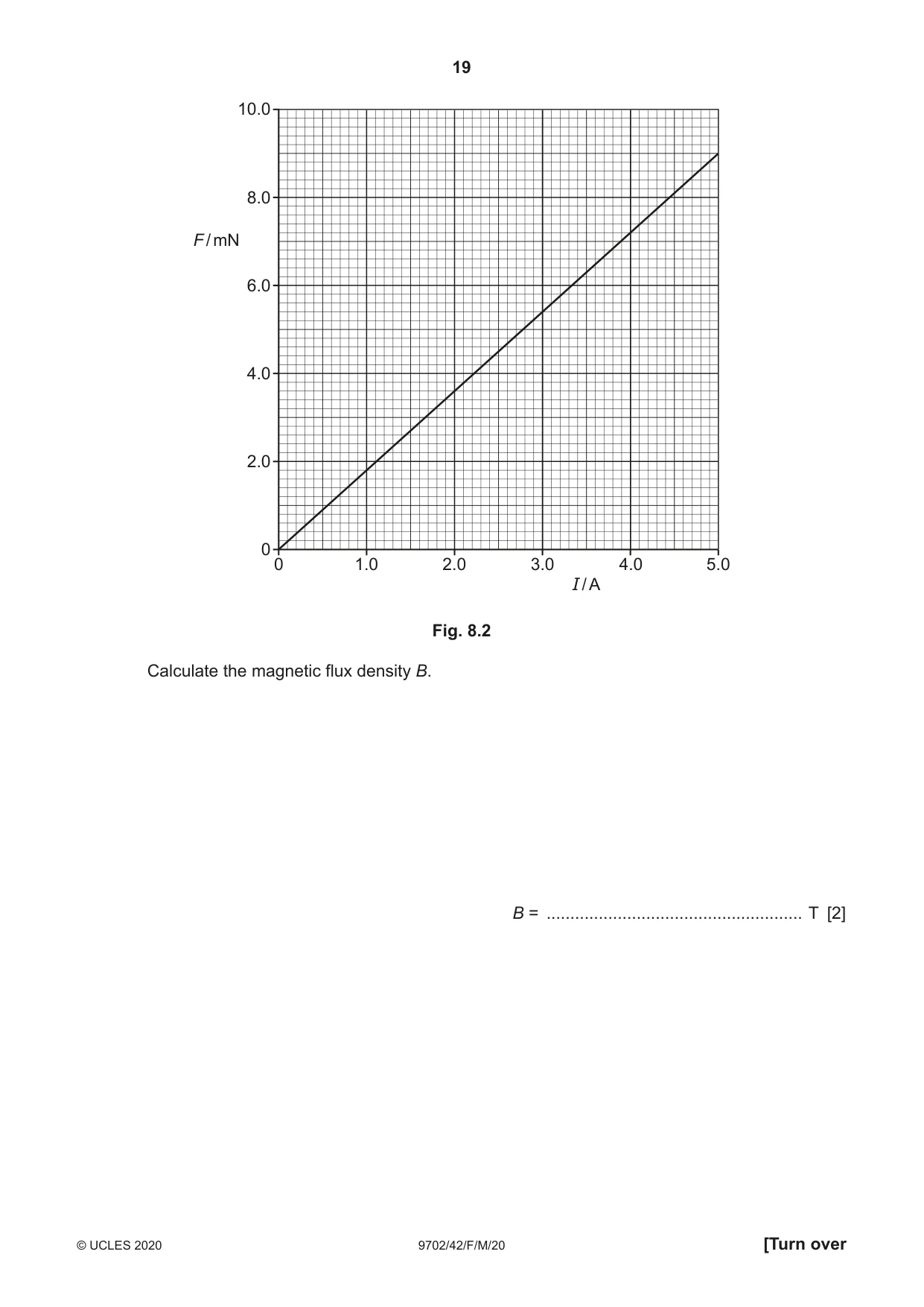
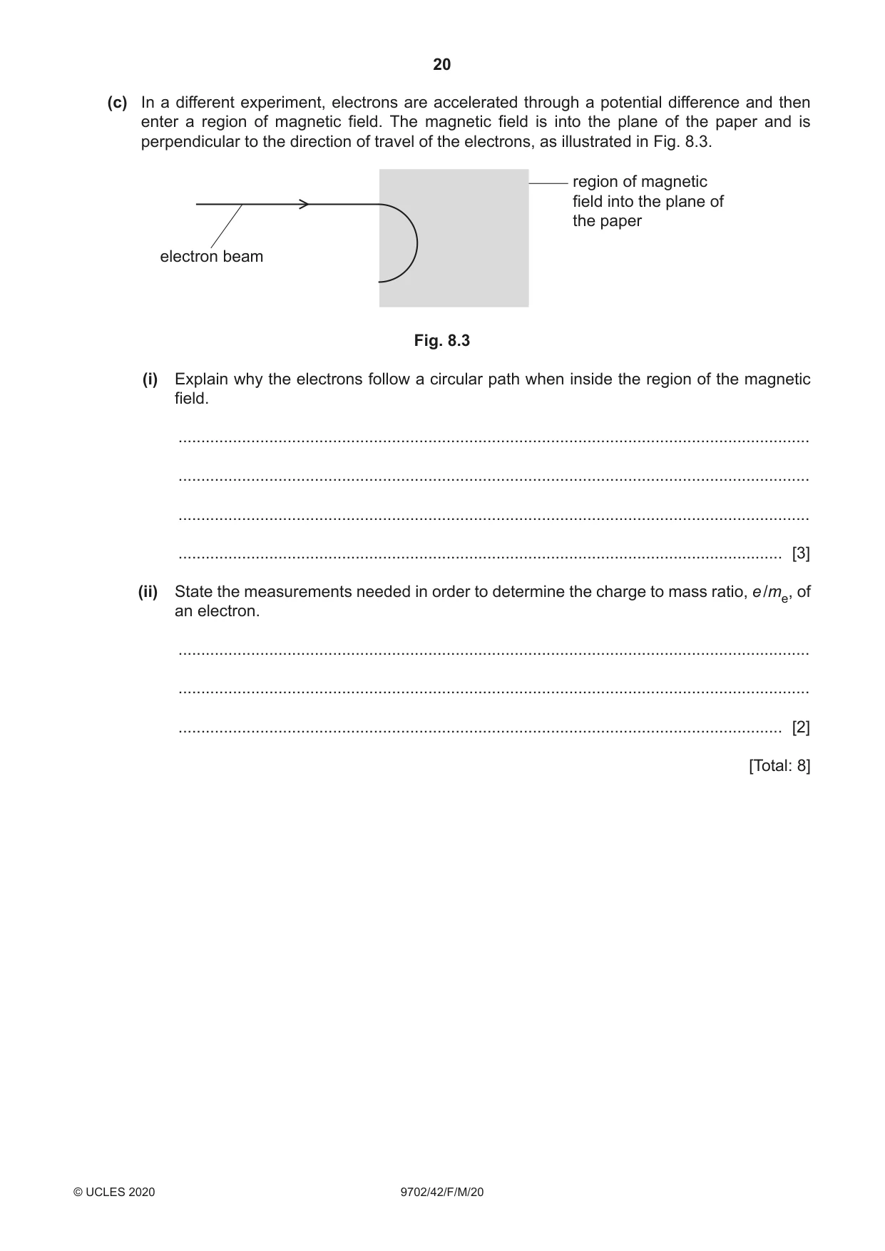
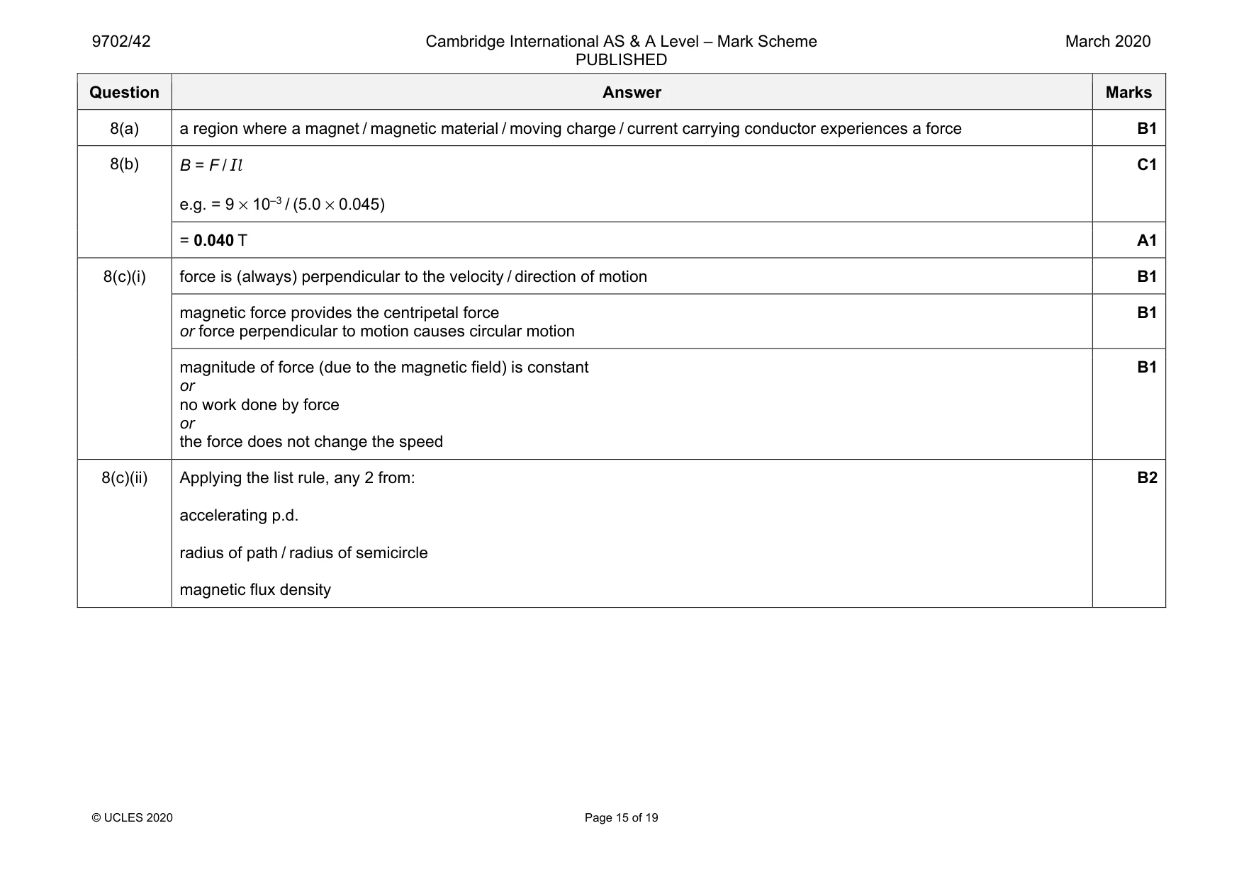
8 (a) Explain what is meant by a magnetic field. ................................................................................................................................................... ................................................................................................................................................... ................................................................................................................................................... ............................................................................................................................................. [1] (b) The apparatus shown in Fig. 8.1 is used in an experiment to find the magnetic flux density B between the poles of a horseshoe magnet. Assume the magnetic field is uniform between the poles of the magnet and zero elsewhere. 45 mm horseshoe magnet 300 mm metal rod balance pan Fig. 8.1 The rigid metal rod of length 300 mm is fixed in position perpendicular to the direction of the magnetic field. The poles of the magnet are both 45 mm long. There is a current in the rod that causes a force on the rod. The balance is used to determine the magnitude of the force. The variation with current I of the force F on the rod is shown in Fig. 8.2. 10.0 8.0 F / mN 6.0 4.0 2.0 0 0 1.0 2.0 3.0 4.0 5.0 I / A Fig. 8.2 Calculate the magnetic flux density B. B = ...................................................... T [2] (c) In a different experiment, electrons are accelerated through a potential difference and then enter a region of magnetic field. The magnetic field is into the plane of the paper and is perpendicular to the direction of travel of the electrons, as illustrated in Fig. 8.3. region of magnetic field into the plane of the paper electron beam Fig. 8.3 (i) Explain why the electrons follow a circular path when inside the region of the magnetic field. ........................................................................................................................................... ........................................................................................................................................... ........................................................................................................................................... ..................................................................................................................................... [3] (ii) State the measurements needed in order to determine the charge to mass ratio, e /me, of an electron. ........................................................................................................................................... ........................................................................................................................................... ..................................................................................................................................... [2] [Total: 8]
Mark scheme: 8(a) a region where a magnet / magnetic material / moving charge / current carrying conductor experiences a force B1 8(b) B = F / Il e.g. = 9 × 10⁻³ / (5.0 × 0.045) C1 = 0.040 T A1 8(c)(i) force is (always) perpendicular to the velocity / direction of motion B1 magnetic force provides the centripetal force or force perpendicular to motion causes circular motion B1 magnitude of force (due to the magnetic field) is constant or no work done by force or the force does not change the speed B1 8(c)(ii) Applying the list rule, any 2 from: accelerating p.d. radius of path / radius of semicircle magnetic flux density B2
Q9 · The output of a power supply is represented by: V = 9.0 sin 20t where V is the potential…
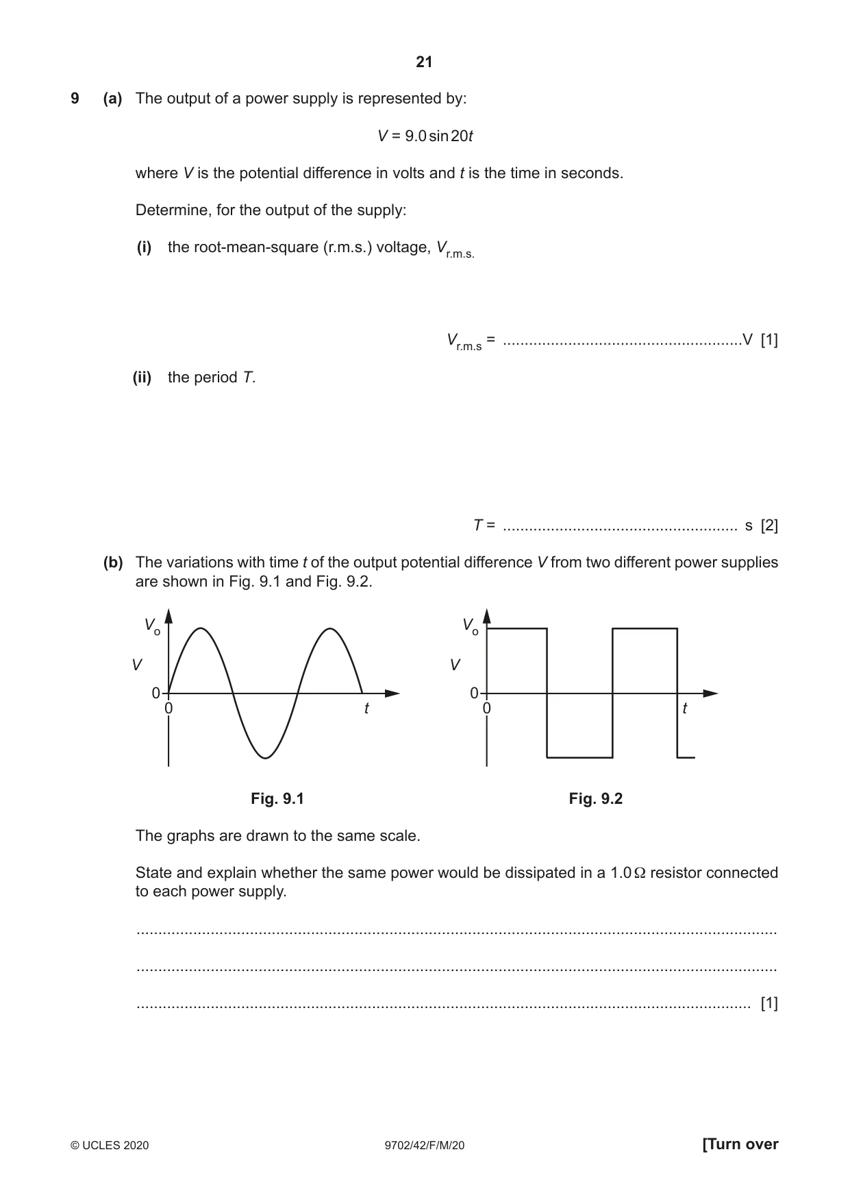
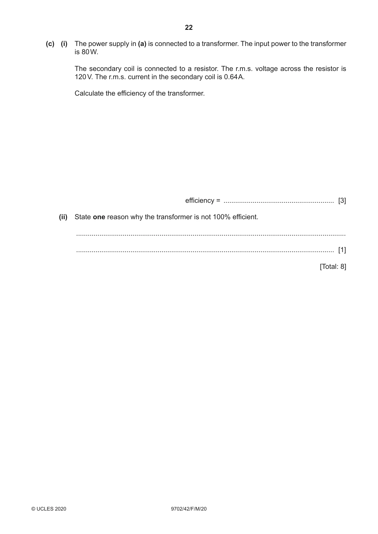
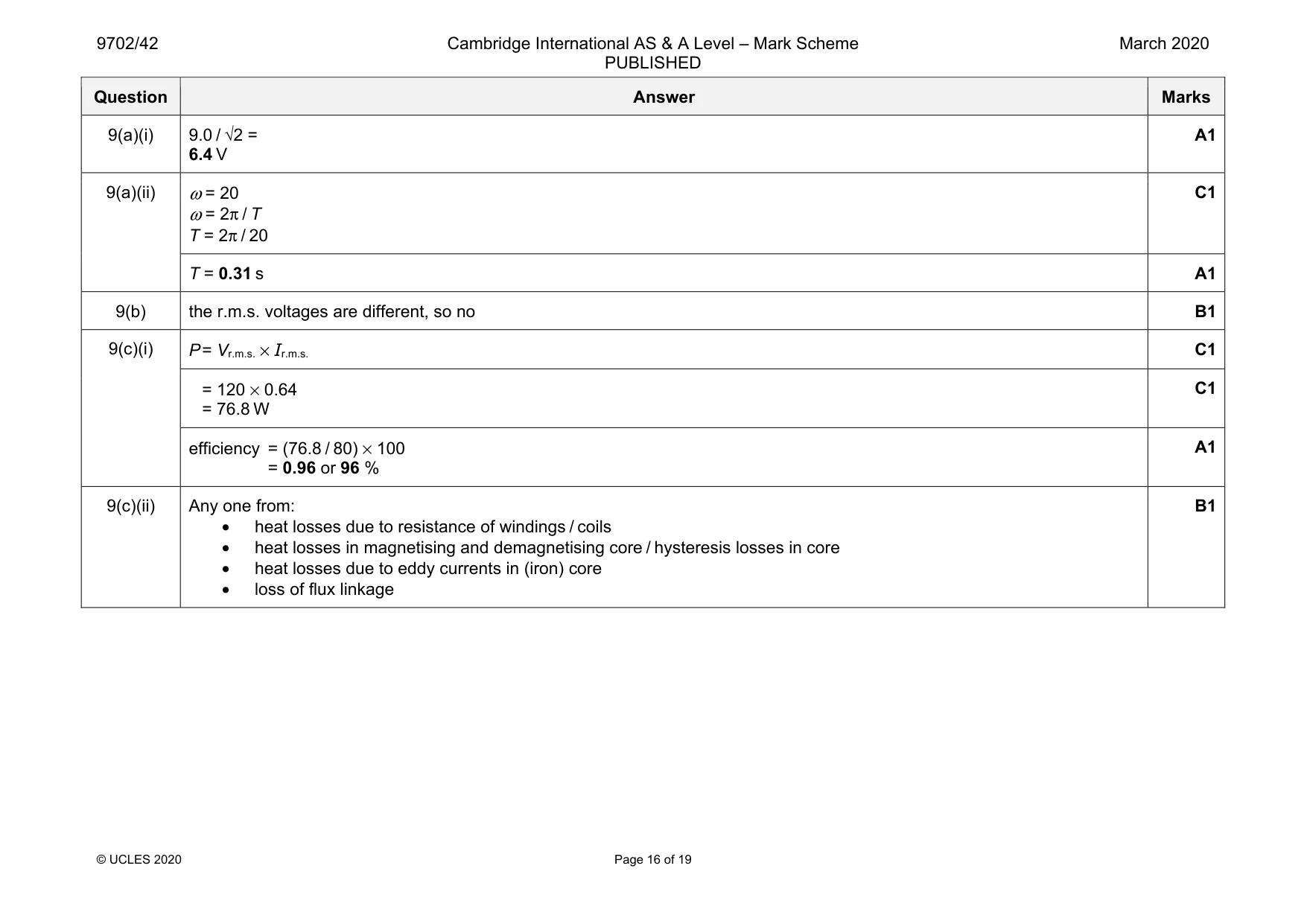
9 (a) The output of a power supply is represented by: V = 9.0 sin 20t where V is the potential difference in volts and t is the time in seconds. Determine, for the output of the supply: (i) the root-mean-square (r.m.s.) voltage, Vr.m.s. Vr.m.s = .......................................................V [1] (ii) the period T. T = ...................................................... s [2] (b) The variations with time t of the output potential difference V from two different power supplies are shown in Fig. 9.1 and Fig. 9.2. Vo Vo V V 0 0 0 t 0 t Fig. 9.1 Fig. 9.2 The graphs are drawn to the same scale. State and explain whether the same power would be dissipated in a 1.0 Ω resistor connected to each power supply. ................................................................................................................................................... ................................................................................................................................................... ............................................................................................................................................. [1] (c) (i) The power supply in (a) is connected to a transformer. The input power to the transformer is 80 W. The secondary coil is connected to a resistor. The r.m.s. voltage across the resistor is 120 V. The r.m.s. current in the secondary coil is 0.64 A. Calculate the efficiency of the transformer. efficiency = ......................................................... [3] (ii) State one reason why the transformer is not 100% efficient. ........................................................................................................................................... ..................................................................................................................................... [1] [Total: 8]
Mark scheme: 9(a)(i) 9.0 / √2 = 6.4 V A1 9(a)(ii) ω = 20 ω = 2π / T T = 2π / 20 C1 T = 0.31 s A1 9(b) the r.m.s. voltages are different, so no B1 9(c)(i) P = Vr.m.s. × Ir.m.s. C1 = 120 × 0.64 = 76.8 W C1 efficiency = (76.8 / 80) × 100 = 0.96 or 96 % A1 9(c)(ii) Any one from: • heat losses due to resistance of windings / coils • heat losses in magnetising and demagnetising core / hysteresis losses in core • heat losses due to eddy currents in (iron) core • loss of flux linkage B1
Q10 · By reference to the photoelectric effect, explain what is meant by work function energy
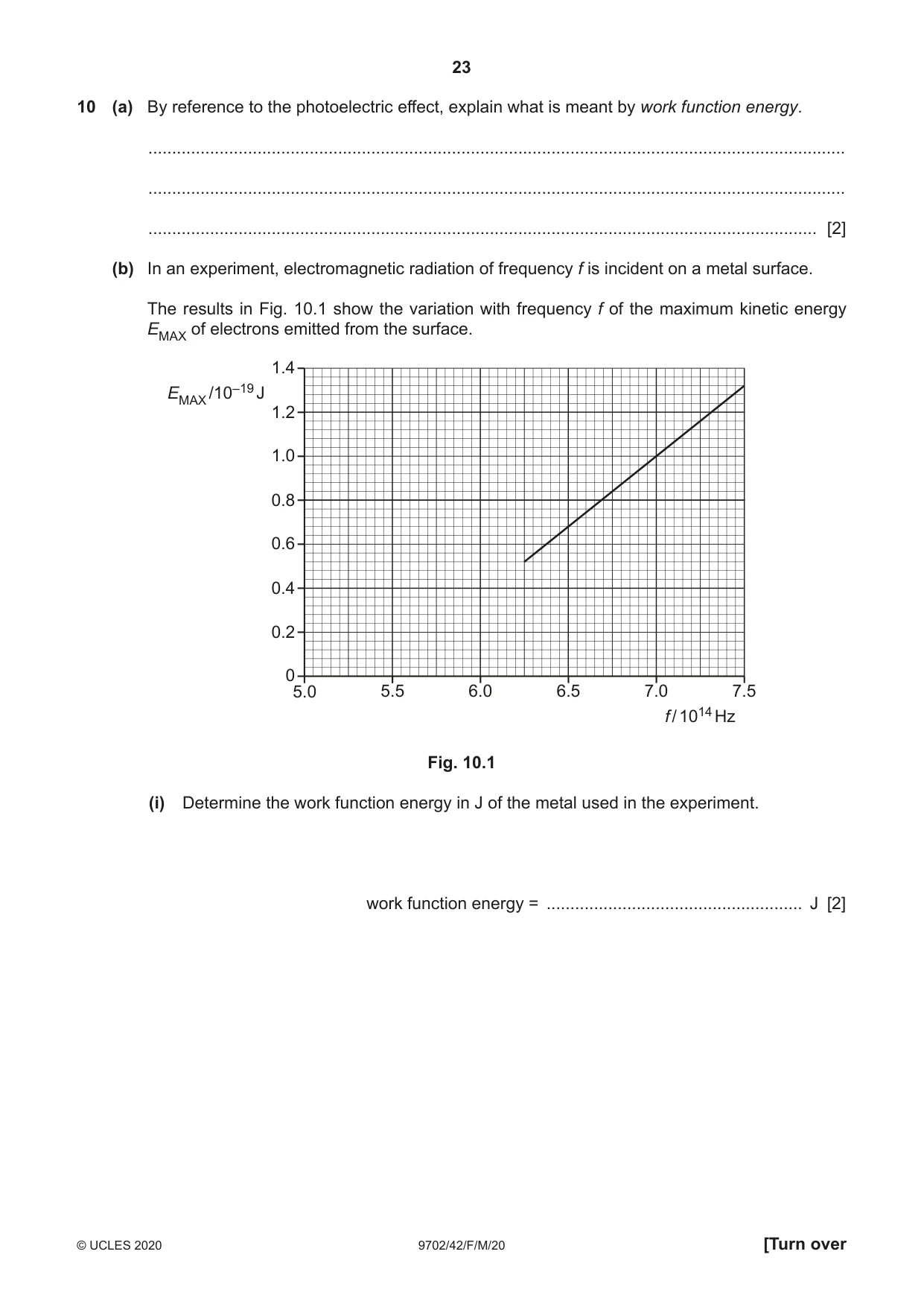
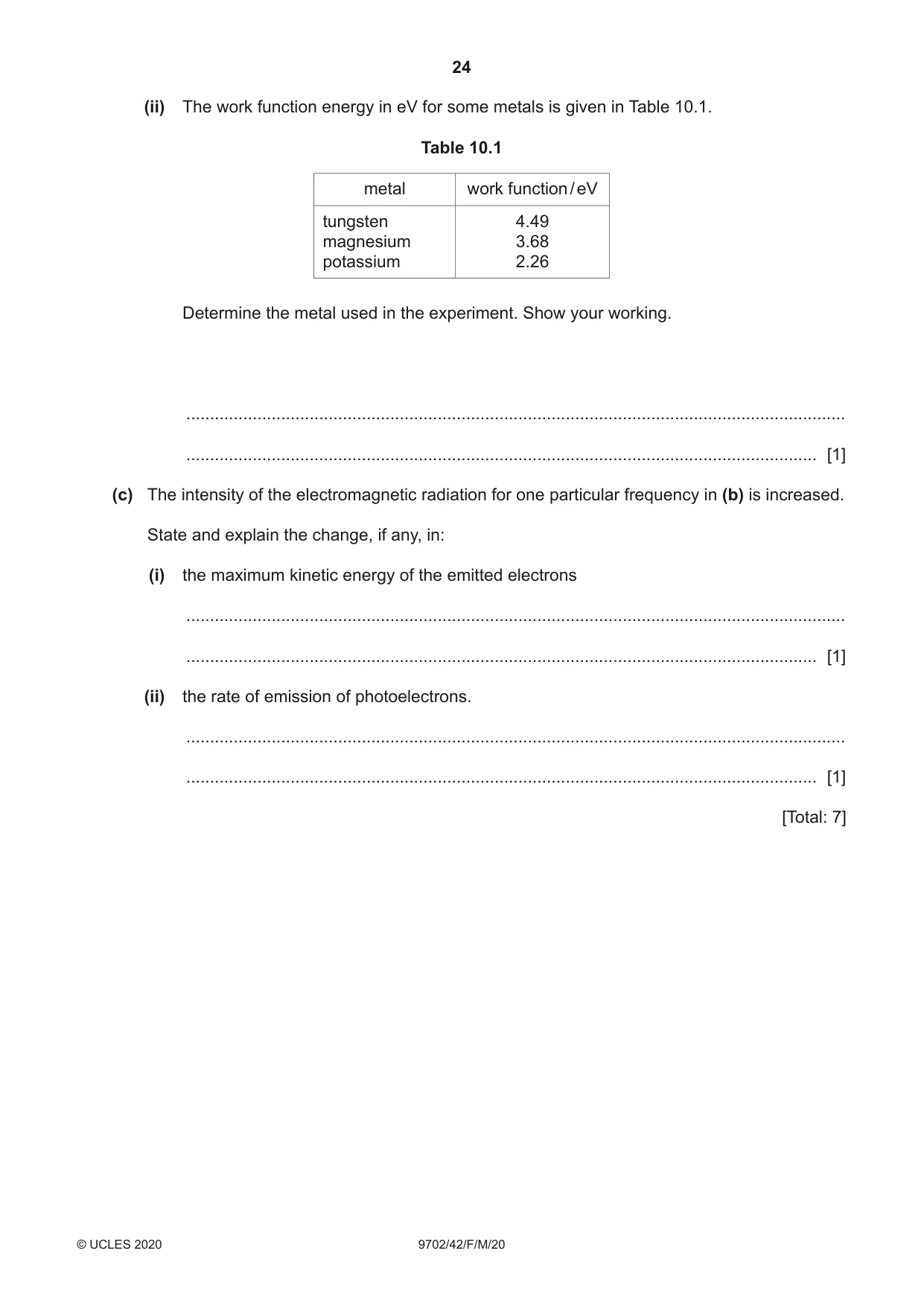
10 (a) By reference to the photoelectric effect, explain what is meant by work function energy. ................................................................................................................................................... ................................................................................................................................................... ............................................................................................................................................. [2] (b) In an experiment, electromagnetic radiation of frequency f is incident on a metal surface. The results in Fig. 10.1 show the variation with frequency f of the maximum kinetic energy EMAX of electrons emitted from the surface. 1.4 EMAX /10–19 J 1.2 1.0 0.8 0.6 0.4 0.2 0 5.0 5.5 6.0 6.5 7.0 7.5 f / 1014 Hz Fig. 10.1 (i) Determine the work function energy in J of the metal used in the experiment. work function energy = ...................................................... J [2] (ii) The work function energy in eV for some metals is given in Table 10.1. Table 10.1 metal work function / eV tungsten 4.49 magnesium 3.68 potassium 2.26 Determine the metal used in the experiment. Show your working. ........................................................................................................................................... ..................................................................................................................................... [1] (c) The intensity of the electromagnetic radiation for one particular frequency in (b) is increased. State and explain the change, if any, in: (i) the maximum kinetic energy of the emitted electrons ........................................................................................................................................... ..................................................................................................................................... [1] (ii) the rate of emission of photoelectrons. ........................................................................................................................................... ..................................................................................................................................... [1] [Total: 7]
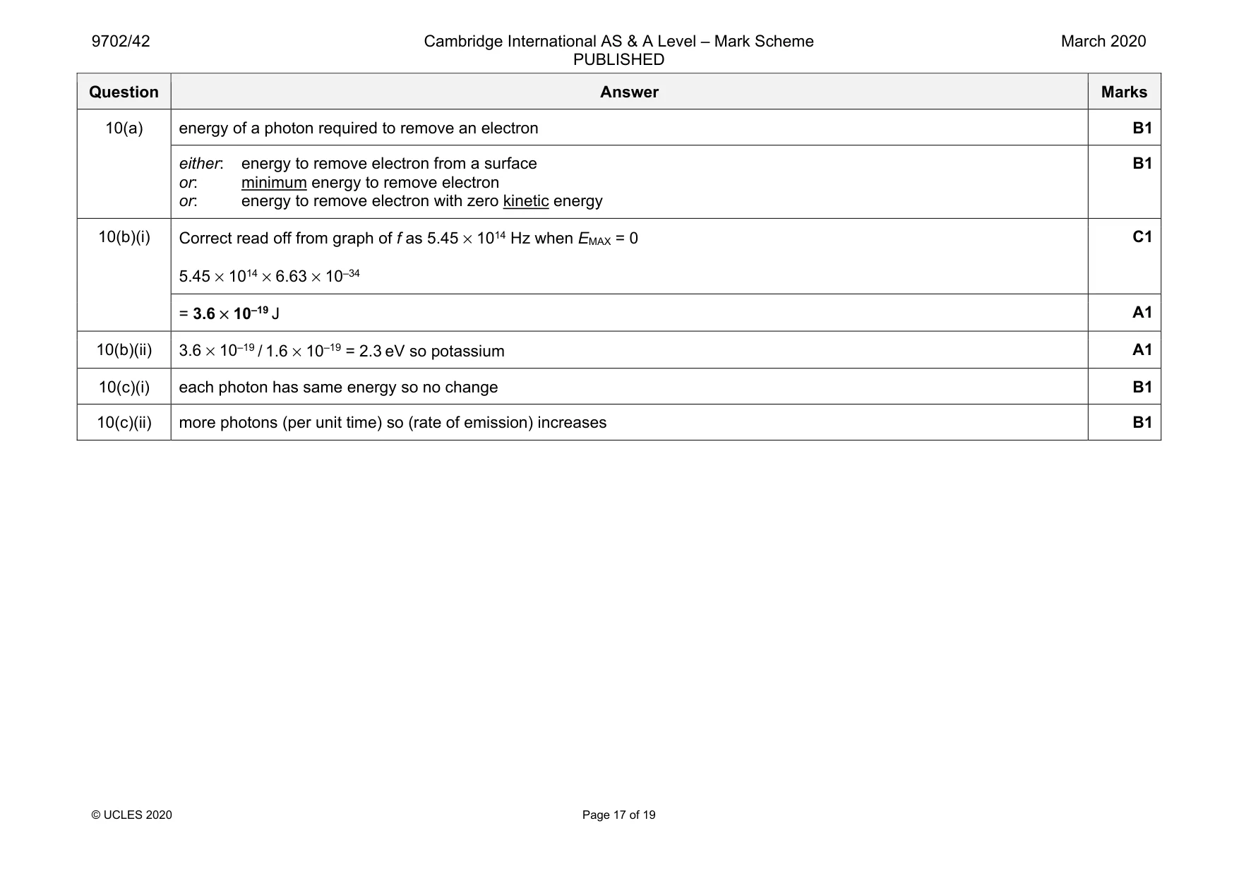
Mark scheme: 10(a) energy of a photon required to remove an electron B1 either: energy to remove electron from a surface or: minimum energy to remove electron or: energy to remove electron with zero kinetic energy B1 10(b)(i) Correct read off from graph of f as 5.45 × 10¹⁴ Hz when EMAX = 0 5.45 × 1014 × 6.63 × 10–34 C1 = 3.6 × 10⁻¹⁹ J A1 10(b)(ii) 3.6 × 10⁻¹⁹ / 1.6 × 10–19 = 2.3 eV so potassium A1 10(c)(i) each photon has same energy so no change B1 10(c)(ii) more photons (per unit time) so (rate of emission) increases B1
Q11 · Electrons are accelerated through a potential difference of 100 kV
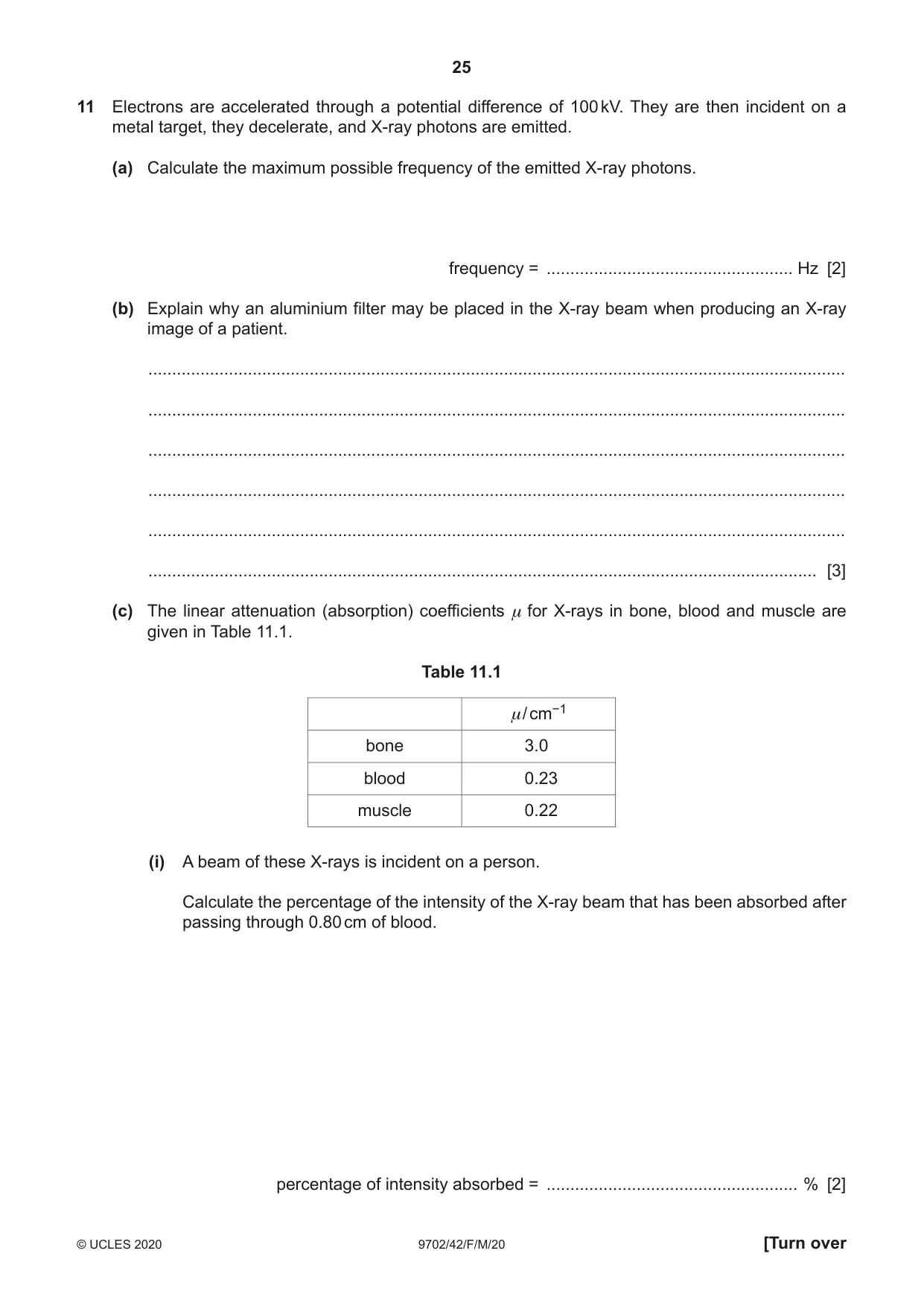
11 Electrons are accelerated through a potential difference of 100 kV. They are then incident on a metal target, they decelerate, and X-ray photons are emitted. (a) Calculate the maximum possible frequency of the emitted X-ray photons. frequency = .................................................... Hz [2] (b) Explain why an aluminium filter may be placed in the X-ray beam when producing an X-ray image of a patient. ................................................................................................................................................... ................................................................................................................................................... ................................................................................................................................................... ................................................................................................................................................... ................................................................................................................................................... ............................................................................................................................................. [3] (c) The linear attenuation (absorption) coefficients μ for X-rays in bone, blood and muscle are given in Table 11.1. Table 11.1 μ/ cm−1 bone 3.0 blood 0.23 muscle 0.22 (i) A beam of these X-rays is incident on a person. Calculate the percentage of the intensity of the X-ray beam that has been absorbed after passing through 0.80 cm of blood. percentage of intensity absorbed = ..................................................... % [2] (ii) In an X-ray image, white regions show greater absorption of X-rays than dark regions. State and explain the difference between the X-ray image of bone compared to that of muscle. ........................................................................................................................................... ........................................................................................................................................... ..................................................................................................................................... [2] [Total: 9]
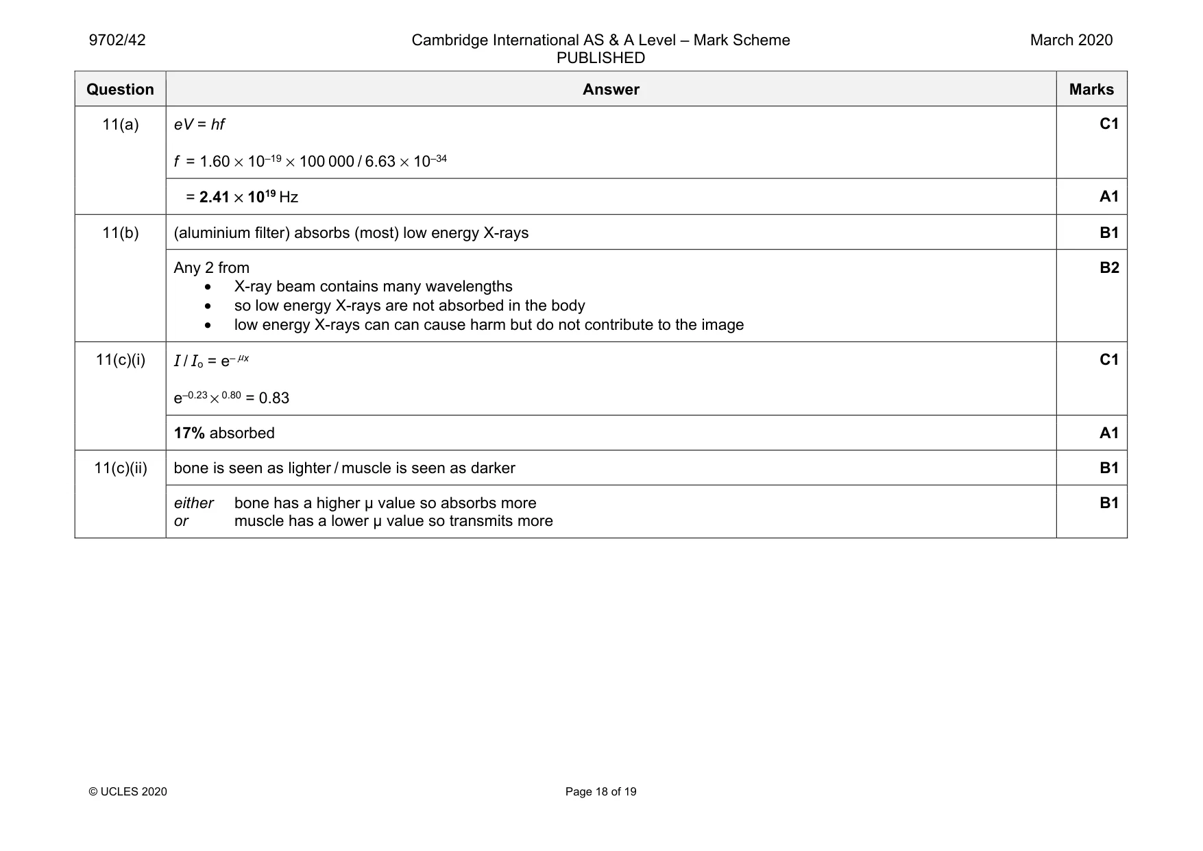
Mark scheme: 11(a) eV = hf f = 1.60 × 10–19 × 100 000 / 6.63 × 10–34 = 2.41 × 10¹⁹ Hz A1 11(b) (aluminium filter) absorbs (most) low energy X-rays B1 Any 2 from • X-ray beam contains many wavelengths • so low energy X-rays are not absorbed in the body • low energy X-rays can can cause harm but do not contribute to the image B2 11(c)(i) I / Io = e– μx e–0.23 × 0.80 = 0.83 C1 17% absorbed A1 11(c)(ii) bone is seen as lighter / muscle is seen as darker B1 either bone has a higher µ value so absorbs more or muscle has a lower µ value so transmits more B1
Q12 · Explain what is meant by the binding energy of a nucleus
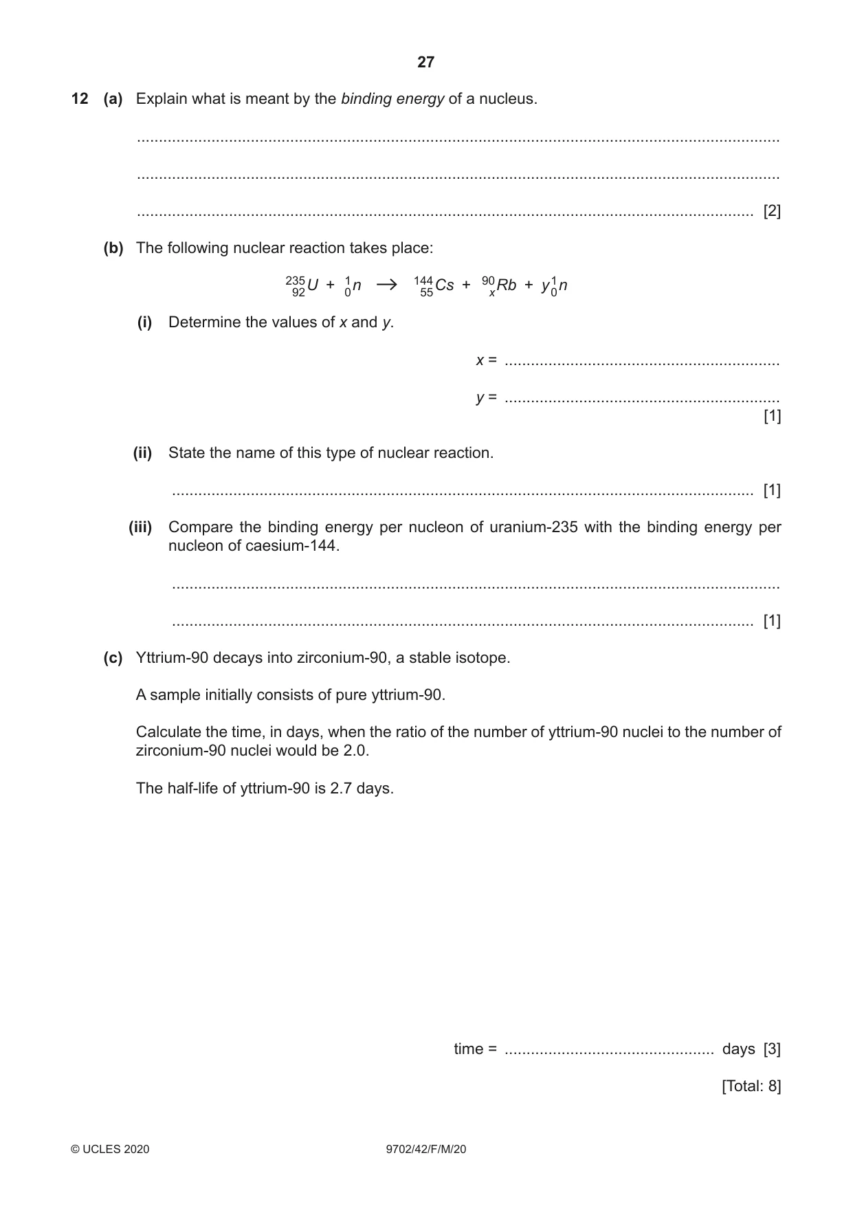
12 (a) Explain what is meant by the binding energy of a nucleus. ................................................................................................................................................... ................................................................................................................................................... ............................................................................................................................................. [2] (b) The following nuclear reaction takes place: 23592 U + 10 n 14455 Cs + 90x Rb + y10 n (i) Determine the values of x and y. x = ............................................................... y = ............................................................... [1] (ii) State the name of this type of nuclear reaction. ..................................................................................................................................... [1] (iii) Compare the binding energy per nucleon of uranium-235 with the binding energy per nucleon of caesium-144. ........................................................................................................................................... ..................................................................................................................................... [1] (c) Yttrium-90 decays into zirconium-90, a stable isotope. A sample initially consists of pure yttrium-90. Calculate the time, in days, when the ratio of the number of yttrium-90 nuclei to the number of zirconium-90 nuclei would be 2.0. The half-life of yttrium-90 is 2.7 days. time = ................................................ days [3] [Total: 8]
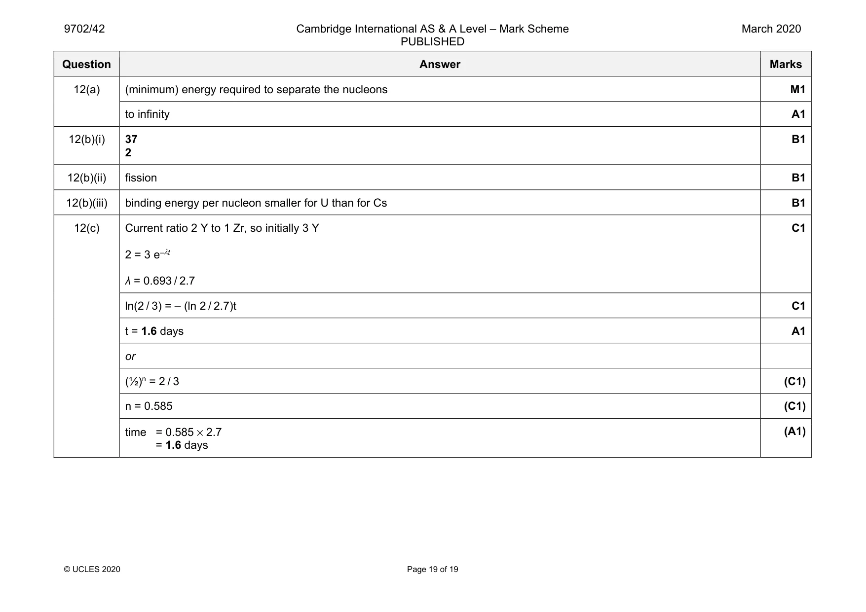
Mark scheme: 12(a) (minimum) energy required to separate the nucleons M1 to infinity A1 12(b)(i) 37 2 B1 12(b)(ii) fission B1 12(b)(iii) binding energy per nucleon smaller for U than for Cs B1 12(c) Current ratio 2 Y to 1 Zr, so initially 3 Y 2 = 3 e–λt λ = 0.693 / 2.7 C1 ln(2 / 3) = – (ln 2 / 2.7)t C1 t = 1.6 days A1 or (½)n = 2 / 3 (C1) n = 0.585 (C1) time = 0.585 × 2.7 = 1.6 days (A1)
What was in this paper
The subtopics covered by these 12 questions, and how many questions each got. Open one in a new tab to see every Cambridge question on it.
1Electric potential1Electromagnetic spectrum1Force on a moving charge1Kinematics of uniform circular motion1Kinetic theory of gases1Photoelectric effect1Production and use of ultrasound1Production and use of X-rays1Radioactive decay1Simple harmonic oscillations1Stress and strain1What you needed in this session
Cambridge’s own grade thresholds for 2020 Feb/March, Paper 4 · Variant 2. A higher threshold means an easier paper — the bar moves with how the cohort did.