Cambridge A Level Physics 9702 — 2018 Oct/Nov Paper 4 · Variant 2
9702/42/O/N/18 · 12 questions · 100 marks · ≈113 min
The question paper and its mark scheme, free to read here and free to download. This is Cambridge’s own paper, exactly as it was sat.
Question paper28 pages

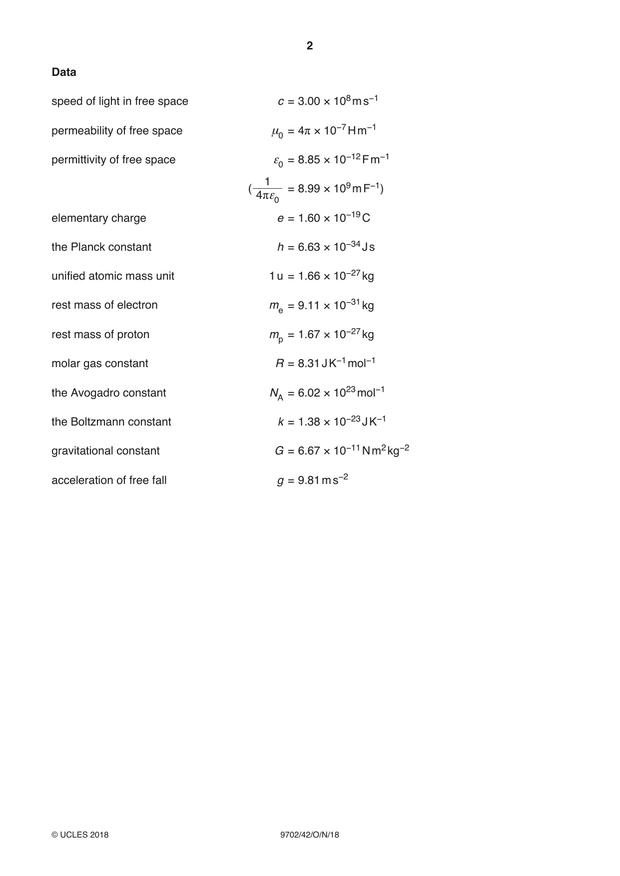
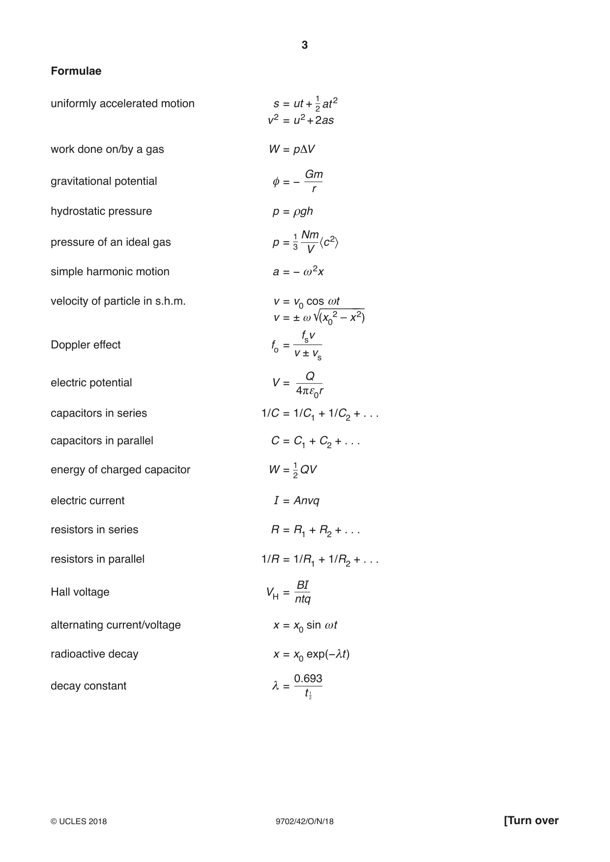

Mark scheme14 pages
Answers below. Sit the paper first if you are practising.
Questions as text
Q1 · State what is meant by gravitational field strength
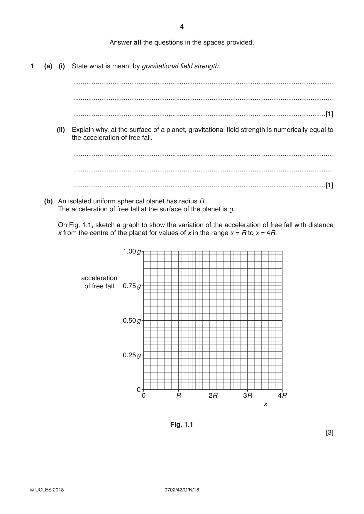
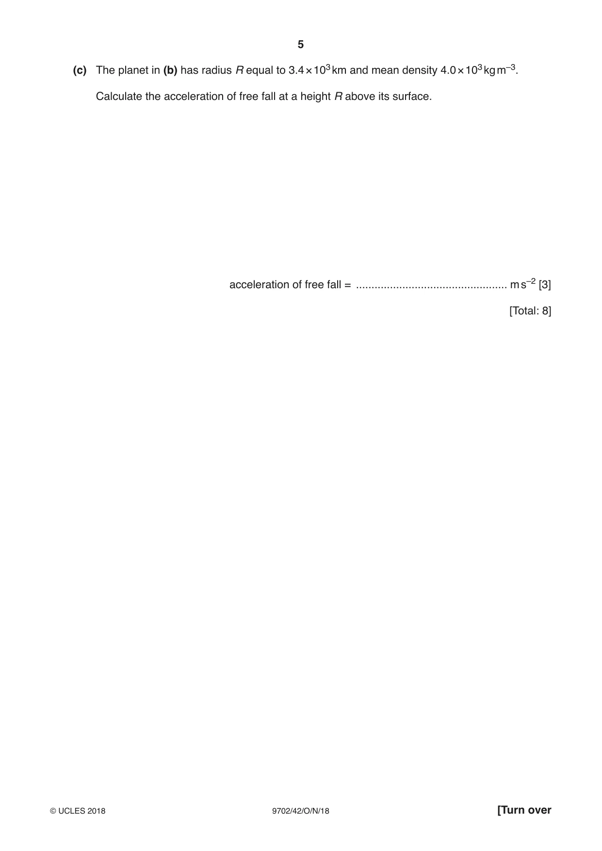
1 (a) (i) State what is meant by gravitational field strength. ........................................................................................................................................... ........................................................................................................................................... .......................................................................................................................................[1] (ii) Explain why, at the surface of a planet, gravitational field strength is numerically equal to the acceleration of free fall. ........................................................................................................................................... ........................................................................................................................................... .......................................................................................................................................[1] (b) An isolated uniform spherical planet has radius R. The acceleration of free fall at the surface of the planet is g. On Fig. 1.1, sketch a graph to show the variation of the acceleration of free fall with distance x from the centre of the planet for values of x in the range x = R to x = 4R. 1.00 g acceleration of free fall 0.75 g 0.50 g 0.25 g 0 0 R 2R 3R 4R x Fig. 1.1 [3] (c) The planet in (b) has radius R equal to 3.4 × 10³ km and mean density 4.0 × 10³ kg m–3. Calculate the acceleration of free fall at a height R above its surface. acceleration of free fall = ................................................. m s–2 [3] [Total: 8]
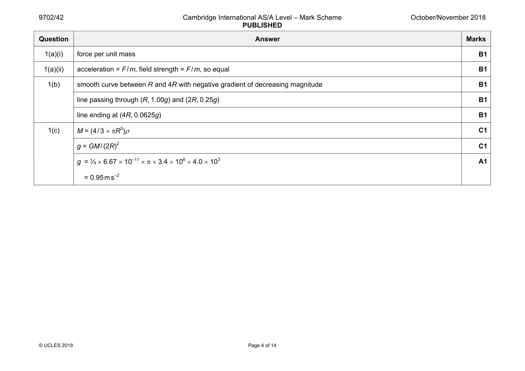
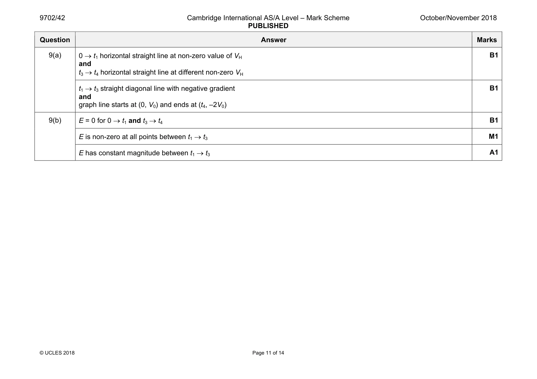
Mark scheme: 1(a)(i) force per unit mass B1 1(a)(ii) acceleration = F / m, field strength = F / m, so equal B1 1(b) smooth curve between R and 4R with negative gradient of decreasing magnitude B1 line passing through (R, 1.00g) and (2R, 0.25g) B1 line ending at (4R, 0.0625g) B1 1(c) M = (4 / 3 × πR3)ρ C1 g = GM / (2R)2 C1 g = ⅓ × 6.67 × 10⁻¹¹ × π × 3.4 × 106 × 4.0 × 103 = 0.95 m s–2 A1
Q2 · State what is meant by an ideal gas
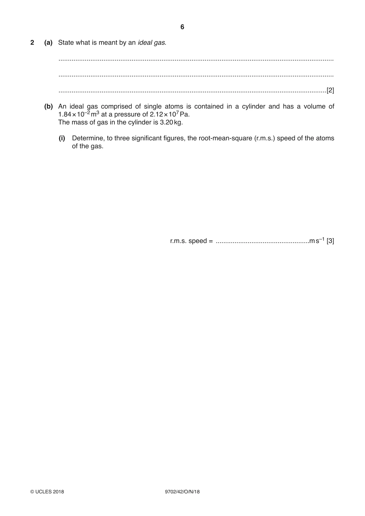
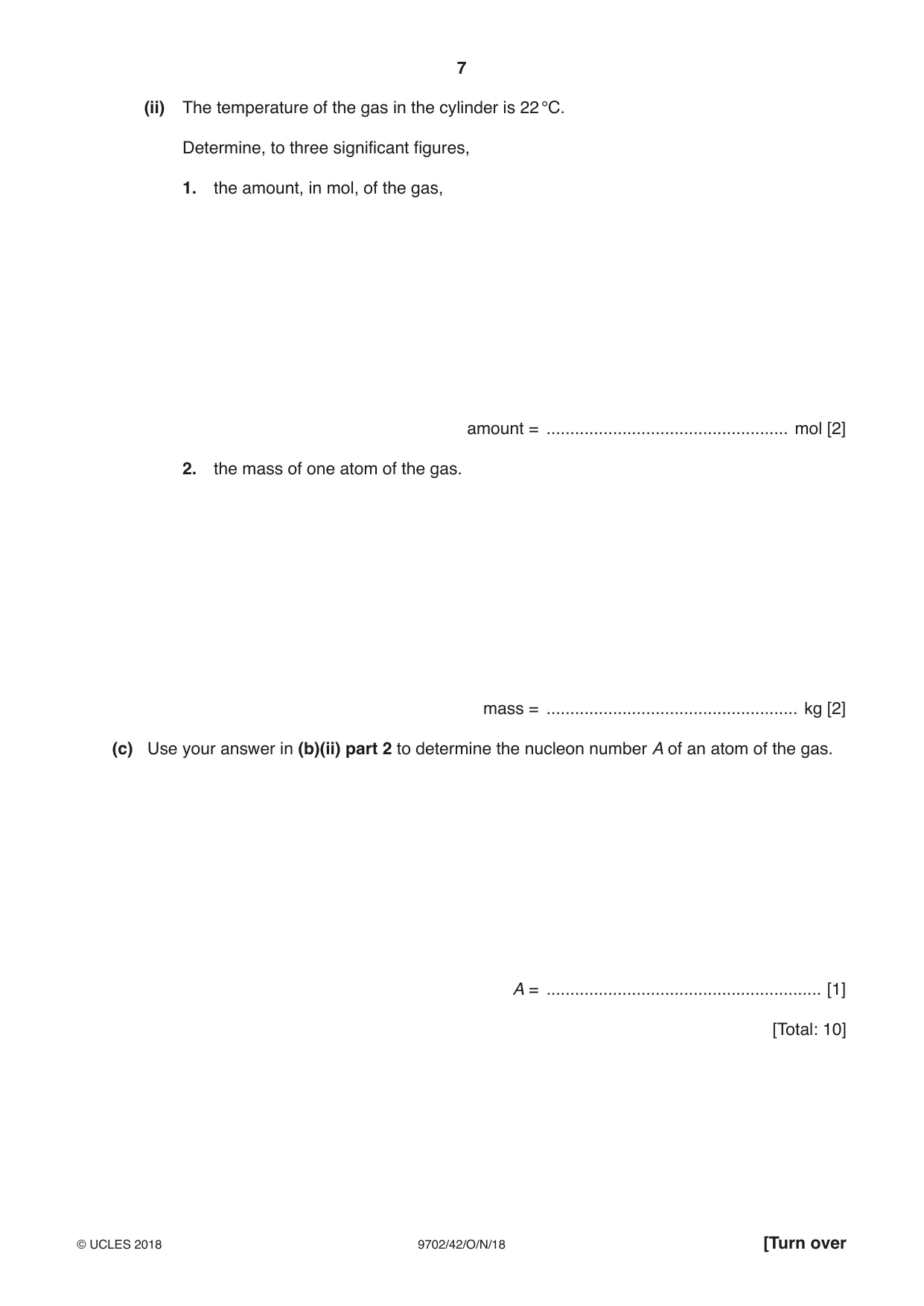
2 (a) State what is meant by an ideal gas. ................................................................................................................................................... ................................................................................................................................................... ...............................................................................................................................................[2] (b) An ideal gas comprised of single atoms is contained in a cylinder and has a volume of 1.84 × 10⁻² m3 at a pressure of 2.12 × 10⁷ Pa. The mass of gas in the cylinder is 3.20 kg. (i) Determine, to three significant figures, the root-mean-square (r.m.s.) speed of the atoms of the gas. r.m.s. speed = ..................................................m s–1 [3] (ii) The temperature of the gas in the cylinder is 22 °C. Determine, to three significant figures, 1. the amount, in mol, of the gas, amount = ................................................... mol [2] 2. the mass of one atom of the gas. mass = ..................................................... kg [2] (c) Use your answer in (b)(ii) part 2 to determine the nucleon number A of an atom of the gas. A = .......................................................... [1] [Total: 10]
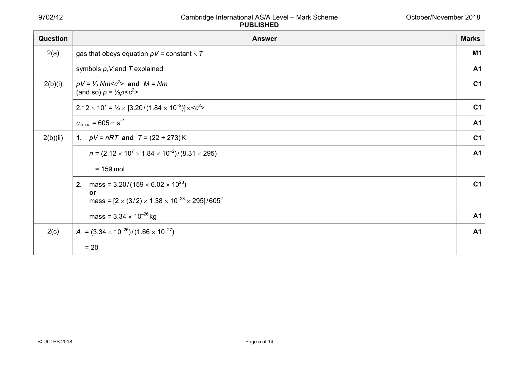
Mark scheme: 2(a) M1 symbols p,V and T explained A1 2(b)(i) pV = ⅓ Nm<c2> and M = Nm (and so) p = ⅓ρ <c2> C1 2.12 × 107 = ⅓ × [3.20 / (1.84 × 10⁻²)] × <c2> C1 cr.m.s. = 605 m s–1 A1 2(b)(ii) 1. pV = nRT and T = (22 + 273) K C1 n = (2.12 × 107 × 1.84 × 10–2) / (8.31 × 295) = 159 mol A1 2. mass = 3.20 / (159 × 6.02 × 1023) or mass = [2 × (3 / 2) × 1.38 × 10–23 × 295] / 6052 C1 mass = 3.34 × 10⁻²⁶ kg A1 2(c) A = (3.34 × 10⁻²⁶) / (1.66 × 10⁻²⁷) = 20 A1
Q3 · Define specific latent heat of fusion
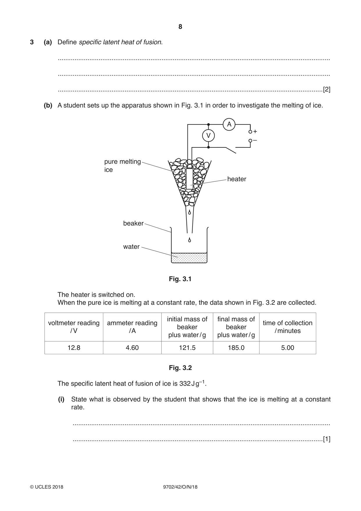
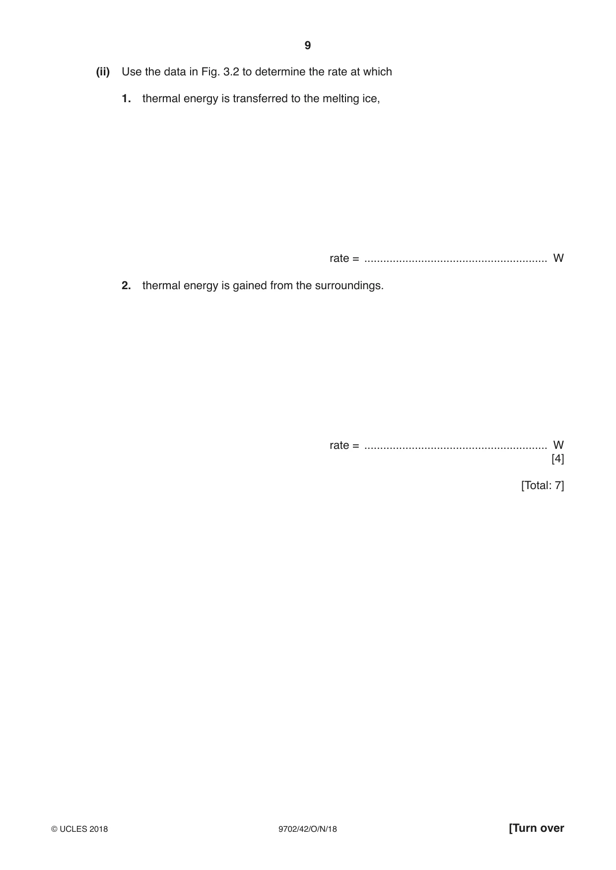
3 (a) Define specific latent heat of fusion. ................................................................................................................................................... ................................................................................................................................................... ...............................................................................................................................................[2] (b) A student sets up the apparatus shown in Fig. 3.1 in order to investigate the melting of ice. A + V – pure melting ice heater beaker water Fig. 3.1 The heater is switched on. When the pure ice is melting at a constant rate, the data shown in Fig. 3.2 are collected. initial mass of final mass of voltmeter reading ammeter reading time of collection beaker beaker / V / A / minutes plus water / g plus water / g 12.8 4.60 121.5 185.0 5.00 Fig. 3.2 The specific latent heat of fusion of ice is 332 J g–1. (i) State what is observed by the student that shows that the ice is melting at a constant rate. ........................................................................................................................................... .......................................................................................................................................[1] (ii) Use the data in Fig. 3.2 to determine the rate at which 1. thermal energy is transferred to the melting ice, rate = .......................................................... W 2. thermal energy is gained from the surroundings. rate = .......................................................... W [4] [Total: 7]
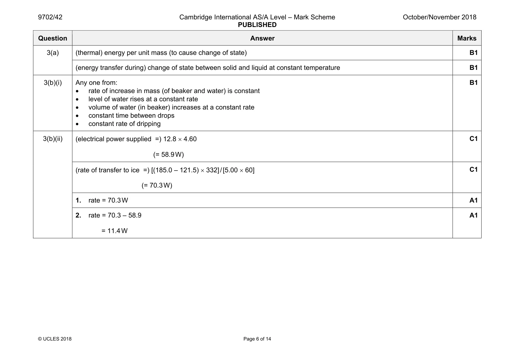
Mark scheme: 3(a) (thermal) energy per unit mass (to cause change of state) B1 (energy transfer during) change of state between solid and liquid at constant temperature B1 3(b)(i) Any one from: • rate of increase in mass (of beaker and water) is constant • level of water rises at a constant rate • volume of water (in beaker) increases at a constant rate • constant time between drops • constant rate of dripping B1 3(b)(ii) (electrical power supplied =) 12.8 × 4.60 (= 58.9 W) C1 (rate of transfer to ice =) [(185.0 – 121.5) × 332] / [5.00 × 60] (= 70.3 W) C1 1. rate = 70.3 W A1 2. rate = 70.3 – 58.9 = 11.4 W A1
More questions on Specific heat capacity and specific latent heat
Q4 · A U-tube contains liquid, as shown in Fig
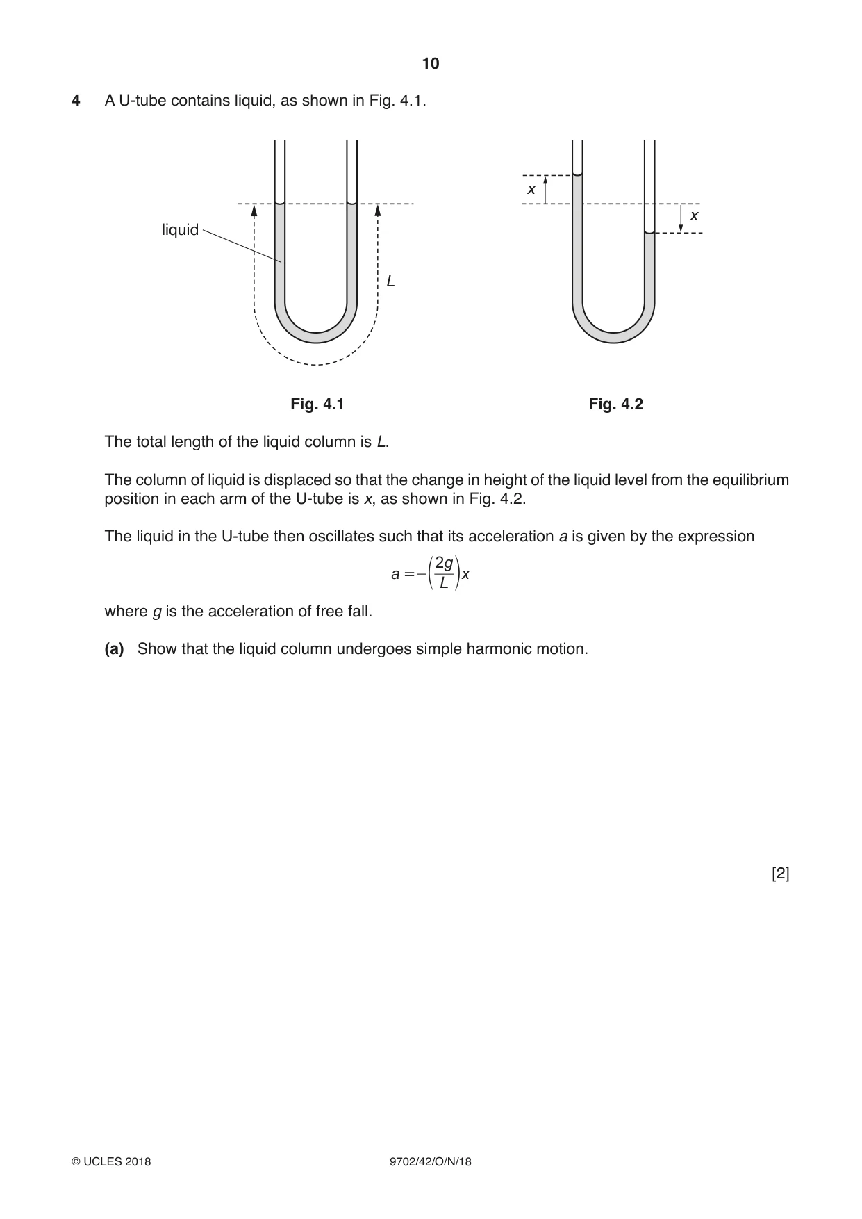
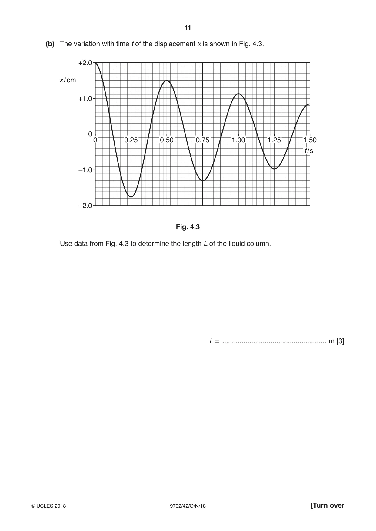
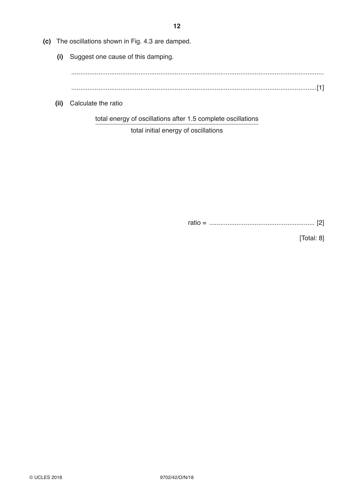
4 A U-tube contains liquid, as shown in Fig. 4.1. x x liquid L Fig. 4.1 Fig. 4.2 The total length of the liquid column is L. The column of liquid is displaced so that the change in height of the liquid level from the equilibrium position in each arm of the U-tube is x, as shown in Fig. 4.2. The liquid in the U-tube then oscillates such that its acceleration a is given by the expression 2 g a x =-d L n where g is the acceleration of free fall. (a) Show that the liquid column undergoes simple harmonic motion. [2] (b) The variation with time t of the displacement x is shown in Fig. 4.3. +2.0 x / cm +1.0 0 0 0.25 0.50 0.75 1.00 1.25 1.50 t / s –1.0 –2.0 Fig. 4.3 Use data from Fig. 4.3 to determine the length L of the liquid column. L = ...................................................... m [3] (c) The oscillations shown in Fig. 4.3 are damped. (i) Suggest one cause of this damping. ........................................................................................................................................... .......................................................................................................................................[1] (ii) Calculate the ratio total energy of oscillations after 1.5 complete oscillations total initial energy of oscillations ratio = .......................................................... [2] [Total: 8]
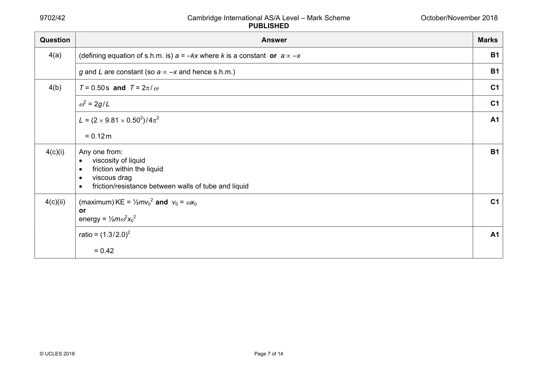
Mark scheme: 4(a) B1 g and L are constant (so a ∝ –x and hence s.h.m.) B1 4(b) T = 0.50 s and T = 2π / ω C1 ω2 = 2g / L C1 L = (2 × 9.81 × 0.502) / 4π2 = 0.12 m A1 4(c)(i) Any one from: • viscosity of liquid • friction within the liquid • viscous drag • friction/resistance between walls of tube and liquid B1 4(c)(ii) (maximum) KE = ½mv0 2 and v0 = ωx0 or energy = ½mω2x0 2 C1 ratio = (1.3 / 2.0)2 = 0.42 A1
Q5 · In radio communication, the radio wave is usually modulated
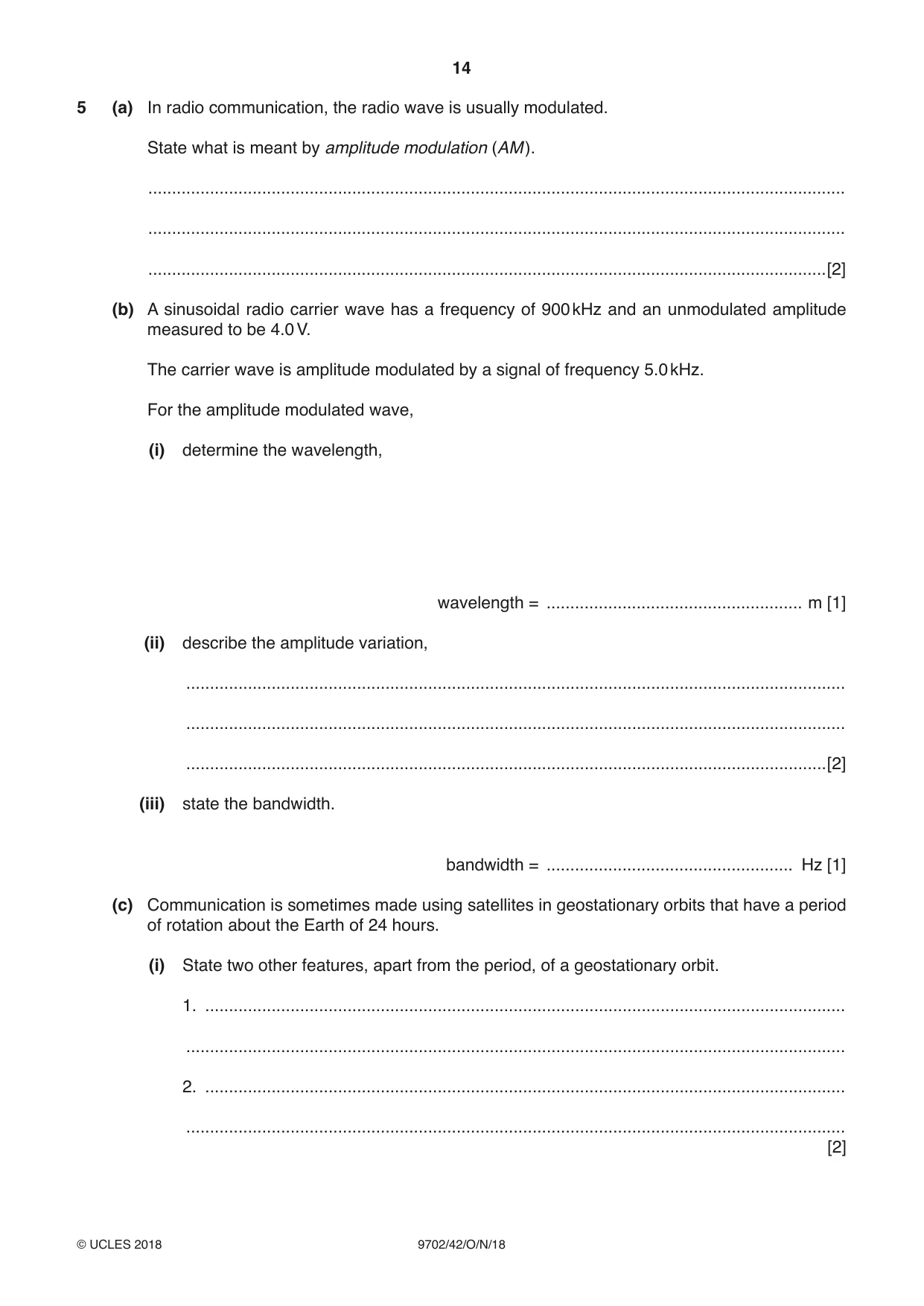
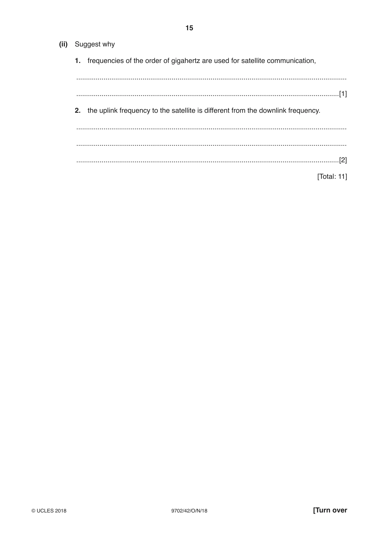
5 (a) In radio communication, the radio wave is usually modulated. State what is meant by amplitude modulation (AM ). ................................................................................................................................................... ................................................................................................................................................... ...............................................................................................................................................[2] (b) A sinusoidal radio carrier wave has a frequency of 900 kHz and an unmodulated amplitude measured to be 4.0 V. The carrier wave is amplitude modulated by a signal of frequency 5.0 kHz. For the amplitude modulated wave, (i) determine the wavelength, wavelength = ...................................................... m [1] (ii) describe the amplitude variation, ........................................................................................................................................... ........................................................................................................................................... .......................................................................................................................................[2] (iii) state the bandwidth. bandwidth = .................................................... Hz [1] (c) Communication is sometimes made using satellites in geostationary orbits that have a period of rotation about the Earth of 24 hours. (i) State two other features, apart from the period, of a geostationary orbit. 1. ....................................................................................................................................... ........................................................................................................................................... 2. ....................................................................................................................................... ........................................................................................................................................... [2] (ii) Suggest why 1. frequencies of the order of gigahertz are used for satellite communication, ........................................................................................................................................... .......................................................................................................................................[1] 2. the uplink frequency to the satellite is different from the downlink frequency. ........................................................................................................................................... ........................................................................................................................................... .......................................................................................................................................[2] [Total: 11]
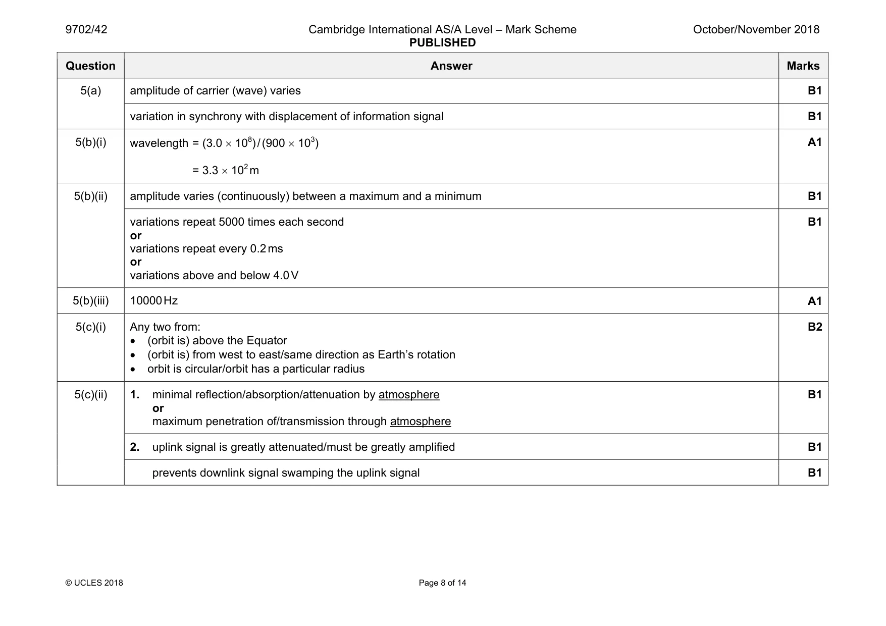
Mark scheme: 5(a) amplitude of carrier (wave) varies B1 variation in synchrony with displacement of information signal B1 5(b)(i) wavelength = (3.0 × 10⁸) / (900 × 103) = 3.3 × 10² m A1 5(b)(ii) amplitude varies (continuously) between a maximum and a minimum B1 variations repeat 5000 times each second or variations repeat every 0.2 ms or variations above and below 4.0 V B1 5(b)(iii) 10000 Hz A1 5(c)(i) Any two from: • (orbit is) above the Equator • (orbit is) from west to east/same direction as Earth’s rotation • orbit is circular/orbit has a particular radius B2 5(c)(ii) 1. minimal reflection/absorption/attenuation by atmosphere or maximum penetration of/transmission through atmosphere B1 2. uplink signal is greatly attenuated/must be greatly amplified B1 prevents downlink signal swamping the uplink signal B1
Q6 · State (i) what is meant by the electric potential at a point…
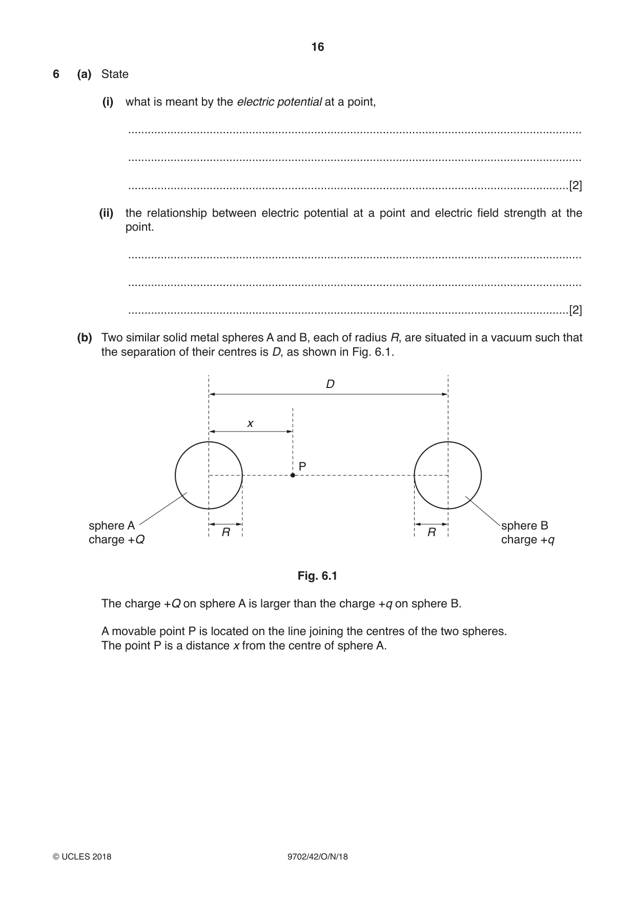
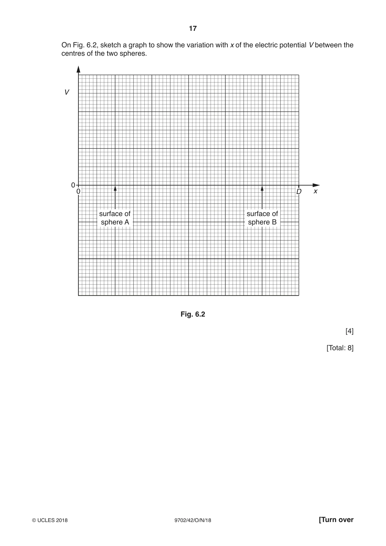
6 (a) State (i) what is meant by the electric potential at a point, ........................................................................................................................................... ........................................................................................................................................... .......................................................................................................................................[2] (ii) the relationship between electric potential at a point and electric field strength at the point. ........................................................................................................................................... ........................................................................................................................................... .......................................................................................................................................[2] (b) Two similar solid metal spheres A and B, each of radius R, are situated in a vacuum such that the separation of their centres is D, as shown in Fig. 6.1. D x P sphere A sphere B R R charge +Q charge +q Fig. 6.1 The charge +Q on sphere A is larger than the charge +q on sphere B. A movable point P is located on the line joining the centres of the two spheres. The point P is a distance x from the centre of sphere A. On Fig. 6.2, sketch a graph to show the variation with x of the electric potential V between the centres of the two spheres. V 0 0 D x surface of surface of sphere A sphere B Fig. 6.2 [4] [Total: 8]
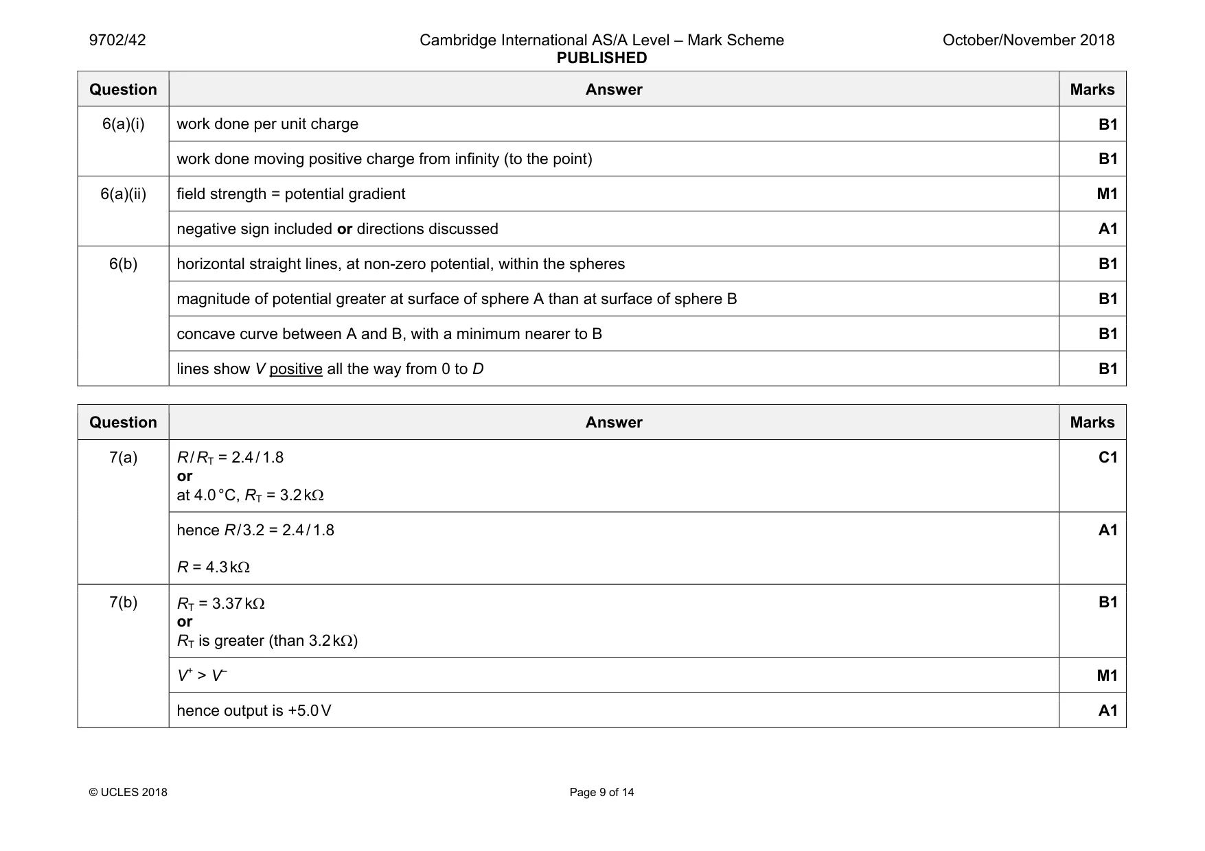
Mark scheme: 6(a)(i) work done per unit charge B1 work done moving positive charge from infinity (to the point) B1 6(a)(ii) field strength = potential gradient M1 negative sign included or directions discussed A1 6(b) horizontal straight lines, at non-zero potential, within the spheres B1 magnitude of potential greater at surface of sphere A than at surface of sphere B B1 concave curve between A and B, with a minimum nearer to B B1 lines show V positive all the way from 0 to D B1
Q7 · A circuit incorporating an ideal operational amplifier (op-amp) is shown in Fig
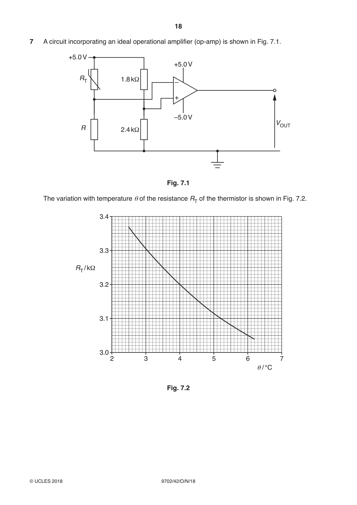
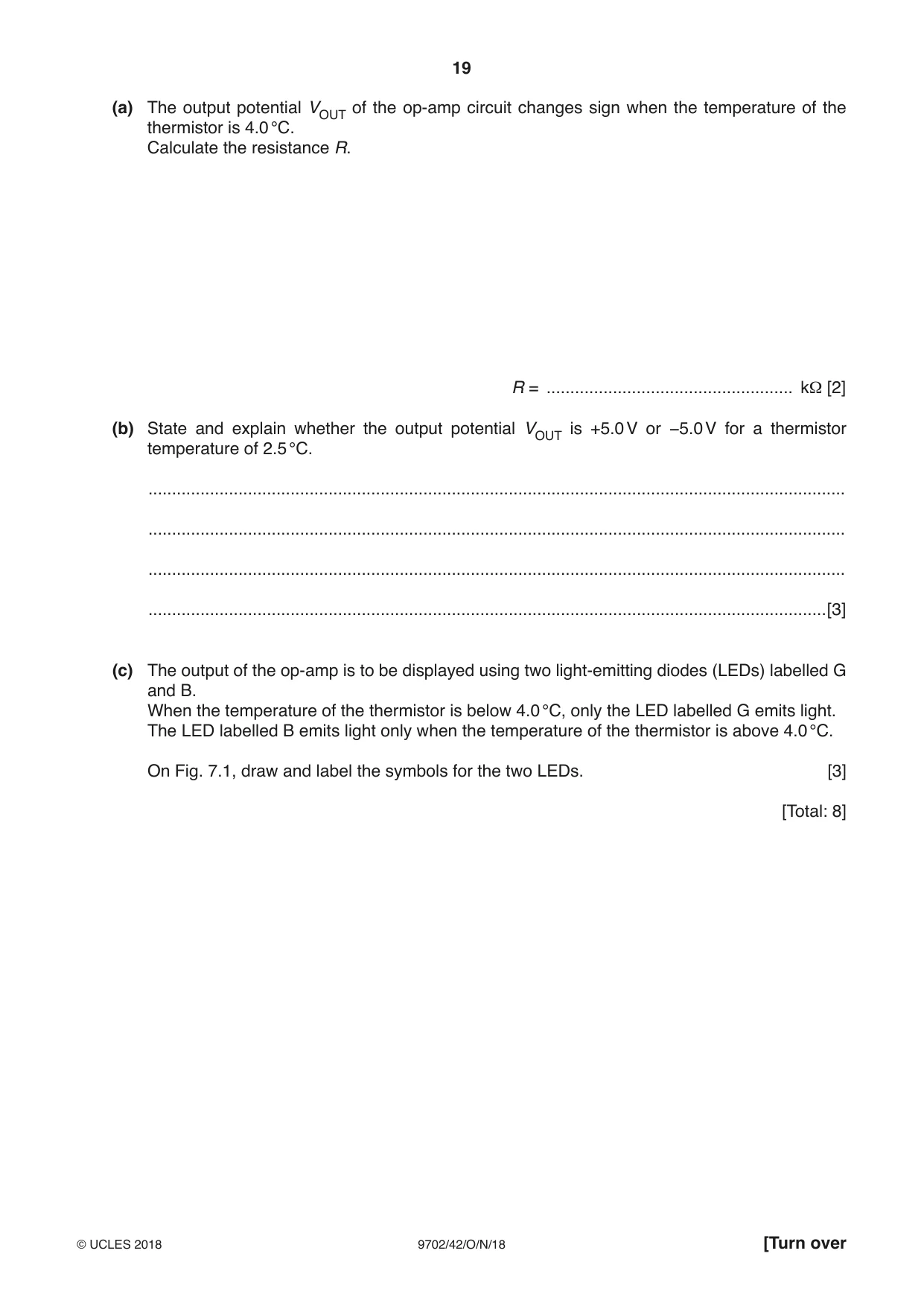
7 A circuit incorporating an ideal operational amplifier (op-amp) is shown in Fig. 7.1. +5.0 V +5.0 V RT 1.8 kΩ – + –5.0 V VOUT R 2.4 kΩ Fig. 7.1 The variation with temperature θ of the resistance RT of the thermistor is shown in Fig. 7.2. 3.4 3.3 Ω RT / k 3.2 3.1 3.0 2 3 4 5 6 7 θ / °C Fig. 7.2 (a) The output potential VOUT of the op-amp circuit changes sign when the temperature of the thermistor is 4.0 °C. Calculate the resistance R. R = .................................................... kΩ [2] (b) State and explain whether the output potential VOUT is +5.0 V or −5.0 V for a thermistor temperature of 2.5 °C. ................................................................................................................................................... ................................................................................................................................................... ................................................................................................................................................... ...............................................................................................................................................[3] (c) The output of the op-amp is to be displayed using two light-emitting diodes (LEDs) labelled G and B. When the temperature of the thermistor is below 4.0 °C, only the LED labelled G emits light. The LED labelled B emits light only when the temperature of the thermistor is above 4.0 °C. On Fig. 7.1, draw and label the symbols for the two LEDs. [3] [Total: 8]
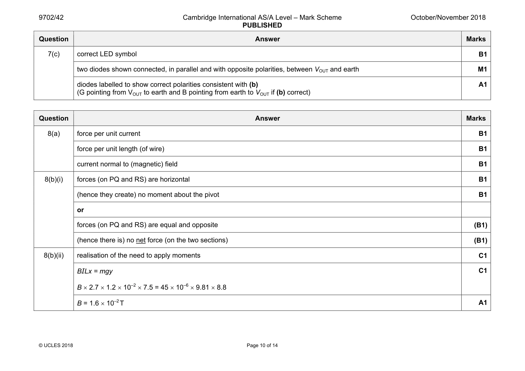
Mark scheme: 7(a) R / RT = 2.4 / 1.8 or at 4.0 °C, RT = 3.2 kΩ C1 hence R / 3.2 = 2.4 / 1.8 R = 4.3 kΩ A1 7(b) RT = 3.37 kΩ or RT is greater (than 3.2 kΩ) B1 V+ > V– M1 hence output is +5.0 V A1 Question Answer Marks 7(c) correct LED symbol B1 two diodes shown connected, in parallel and with opposite polarities, between VOUT and earth M1 diodes labelled to show correct polarities consistent with (b) (G pointing from VOUT to earth and B pointing from earth to VOUT if (b) correct) A1
Q8 · Define magnetic flux density
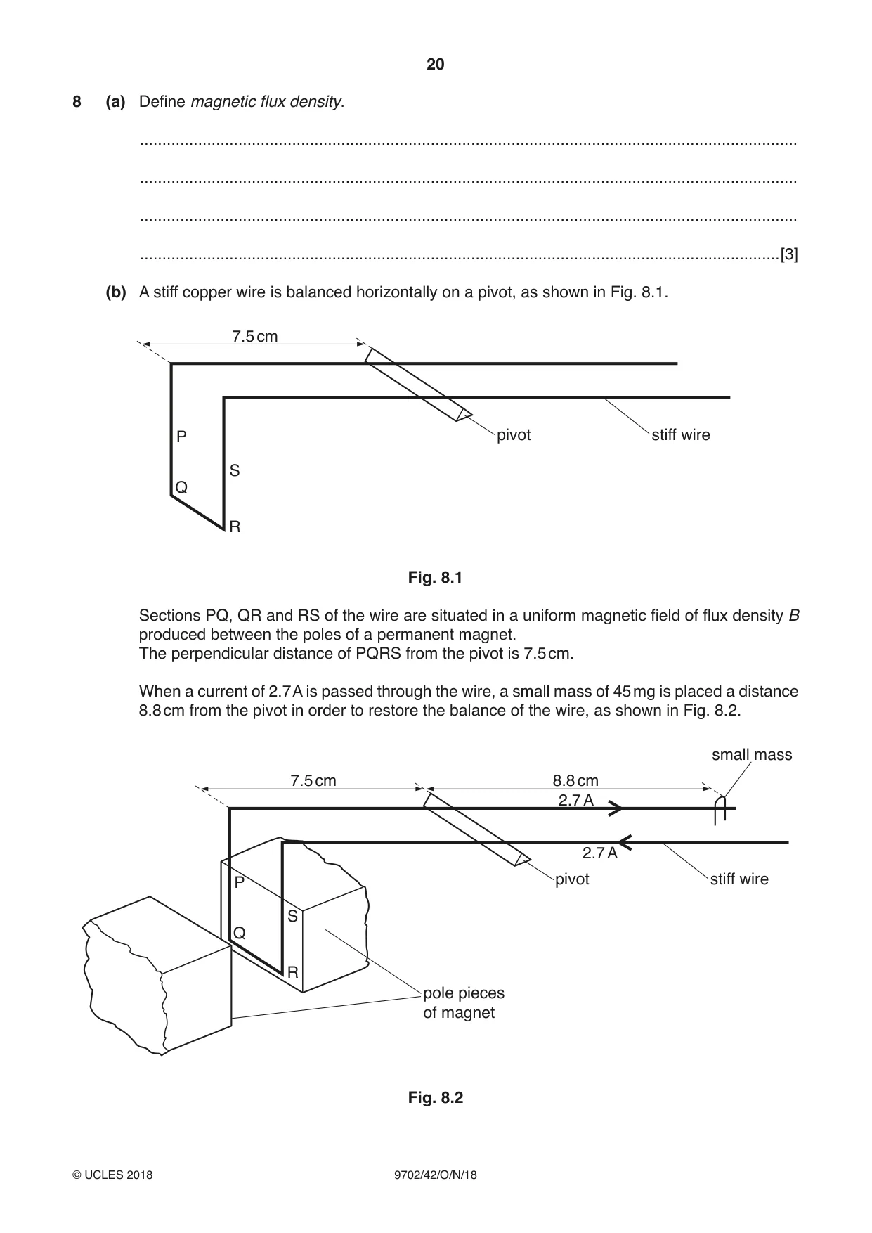
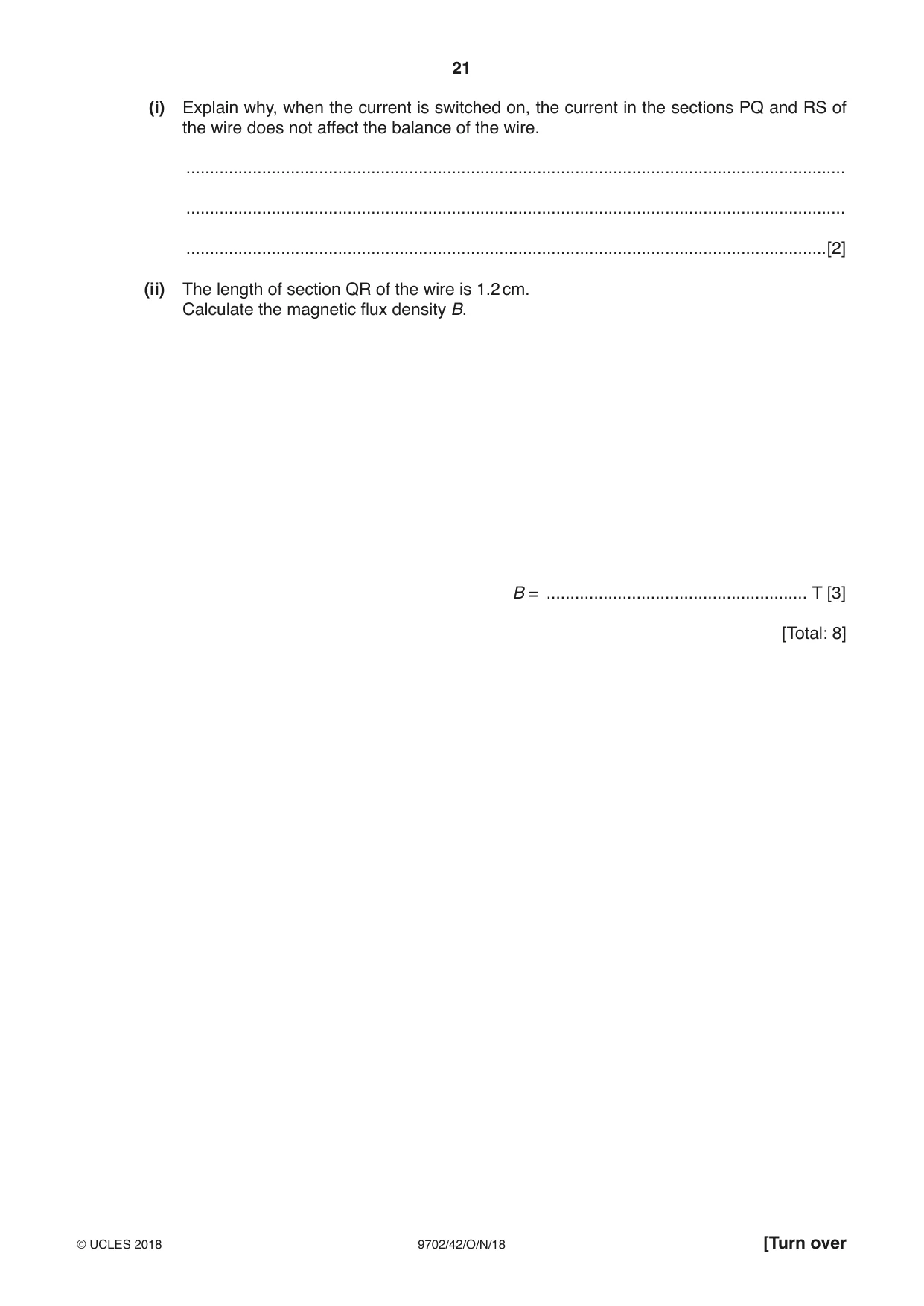
8 (a) Define magnetic flux density. ................................................................................................................................................... ................................................................................................................................................... ................................................................................................................................................... ...............................................................................................................................................[3] (b) A stiff copper wire is balanced horizontally on a pivot, as shown in Fig. 8.1. 7.5 cm P pivot stiff wire S Q R Fig. 8.1 Sections PQ, QR and RS of the wire are situated in a uniform magnetic field of flux density B produced between the poles of a permanent magnet. The perpendicular distance of PQRS from the pivot is 7.5 cm. When a current of 2.7 A is passed through the wire, a small mass of 45 mg is placed a distance 8.8 cm from the pivot in order to restore the balance of the wire, as shown in Fig. 8.2. small mass 7.5 cm 8.8 cm 2.7 A 2.7 A P pivot stiff wire S Q R pole pieces of magnet Fig. 8.2 (i) Explain why, when the current is switched on, the current in the sections PQ and RS of the wire does not affect the balance of the wire. ........................................................................................................................................... ........................................................................................................................................... .......................................................................................................................................[2] (ii) The length of section QR of the wire is 1.2 cm. Calculate the magnetic flux density B. B = ....................................................... T [3] [Total: 8]
Mark scheme: 8(a) force per unit current B1 force per unit length (of wire) B1 current normal to (magnetic) field B1 8(b)(i) forces (on PQ and RS) are horizontal B1 (hence they create) no moment about the pivot B1 or forces (on PQ and RS) are equal and opposite (B1) (hence there is) no net force (on the two sections) (B1) 8(b)(ii) realisation of the need to apply moments C1 BILx = mgy B × 2.7 × 1.2 × 10–2 × 7.5 = 45 × 10–6 × 9.81 × 8.8 C1 B = 1.6 × 10⁻² T A1
Q9 · A Hall probe is placed near one end of a solenoid that has been wound on a soft-iron…
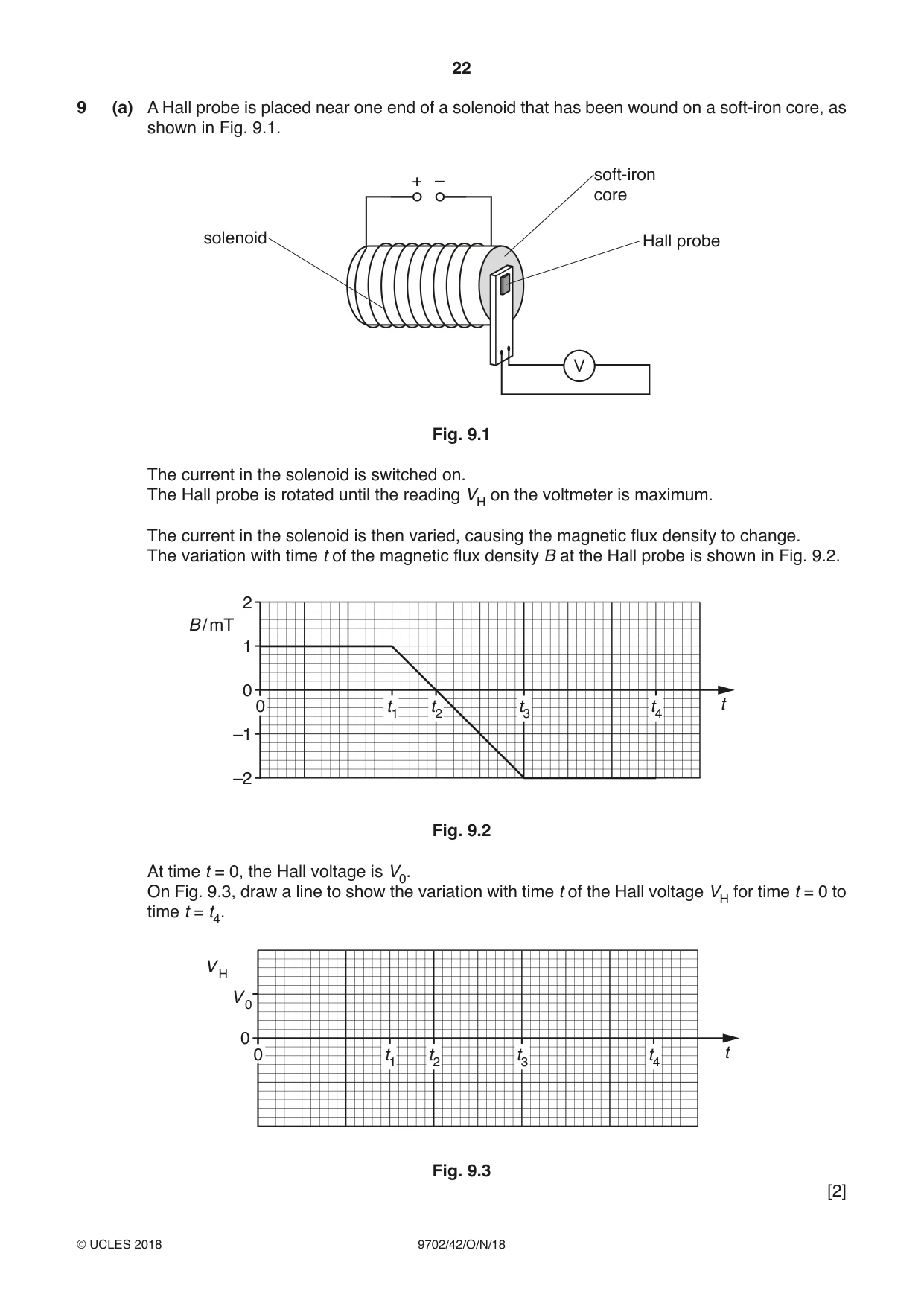
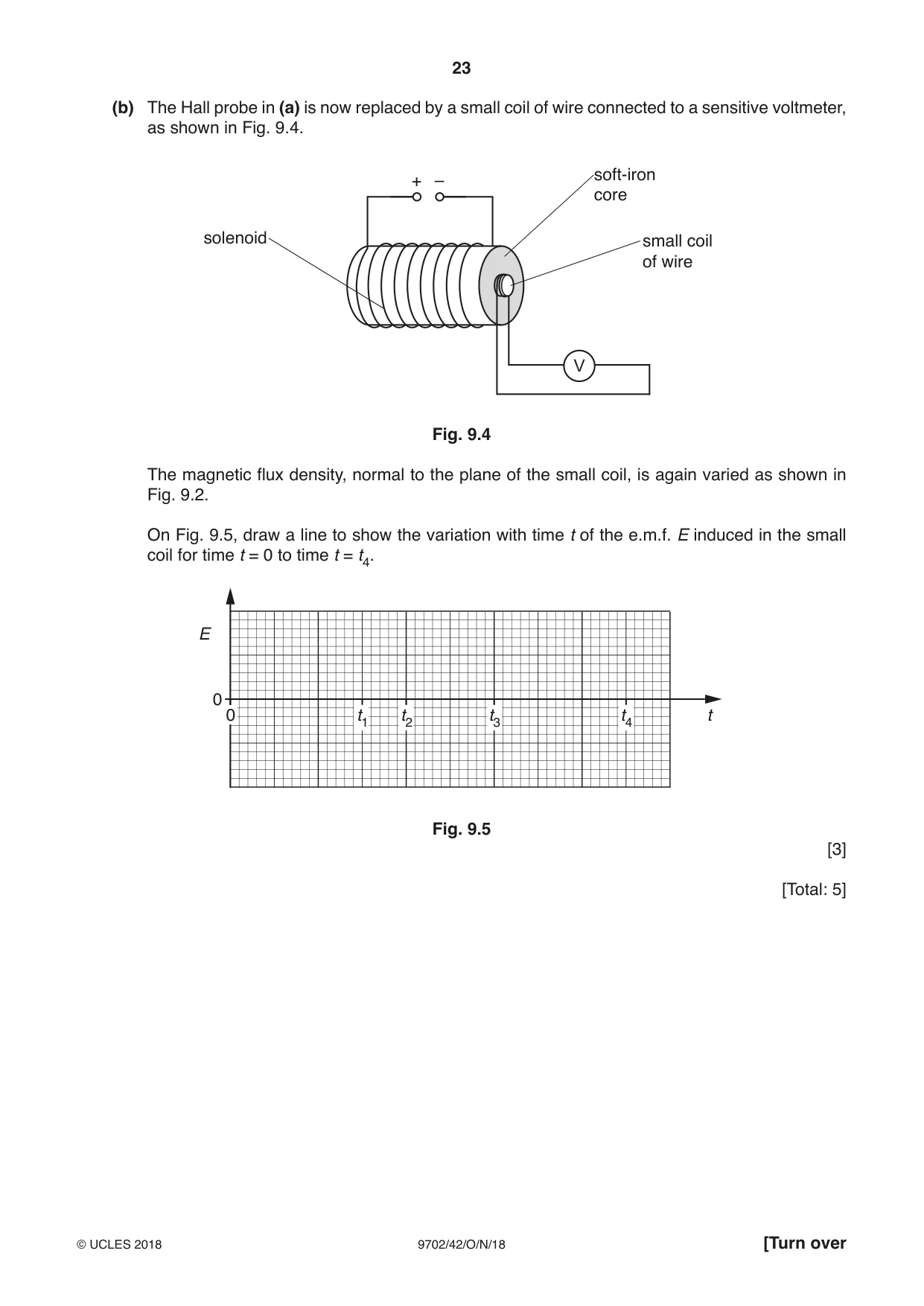
9 (a) A Hall probe is placed near one end of a solenoid that has been wound on a soft-iron core, as shown in Fig. 9.1. soft-iron + – core solenoid Hall probe V Fig. 9.1 The current in the solenoid is switched on. The Hall probe is rotated until the reading VH on the voltmeter is maximum. The current in the solenoid is then varied, causing the magnetic flux density to change. The variation with time t of the magnetic flux density B at the Hall probe is shown in Fig. 9.2. 2 B / mT 1 0 0 t1 t2 t3 t4 t –1 –2 Fig. 9.2 At time t = 0, the Hall voltage is V0. On Fig. 9.3, draw a line to show the variation with time t of the Hall voltage VH for time t = 0 to time t = t4. V H V 0 0 0 t1 t2 t3 t4 t Fig. 9.3 [2] (b) The Hall probe in (a) is now replaced by a small coil of wire connected to a sensitive voltmeter, as shown in Fig. 9.4. soft-iron + – core solenoid small coil of wire V Fig. 9.4 The magnetic flux density, normal to the plane of the small coil, is again varied as shown in Fig. 9.2. On Fig. 9.5, draw a line to show the variation with time t of the e.m.f. E induced in the small coil for time t = 0 to time t = t4. E 0 0 t1 t2 t3 t4 t Fig. 9.5 [3] [Total: 5]
Mark scheme: 9(a) and t3 → t4 horizontal straight line at different non-zero VH B1 t1 → t3 straight diagonal line with negative gradient and graph line starts at (0, V0) and ends at (t4, –2V0) B1 9(b) E = 0 for 0 → t1 and t3 → t4 B1 E is non-zero at all points between t1 → t3 M1 E has constant magnitude between t1 → t3 A1
Q10 · The root-mean-square (r.m.s.) value of the voltage of a sinusoidal alternating supply is…
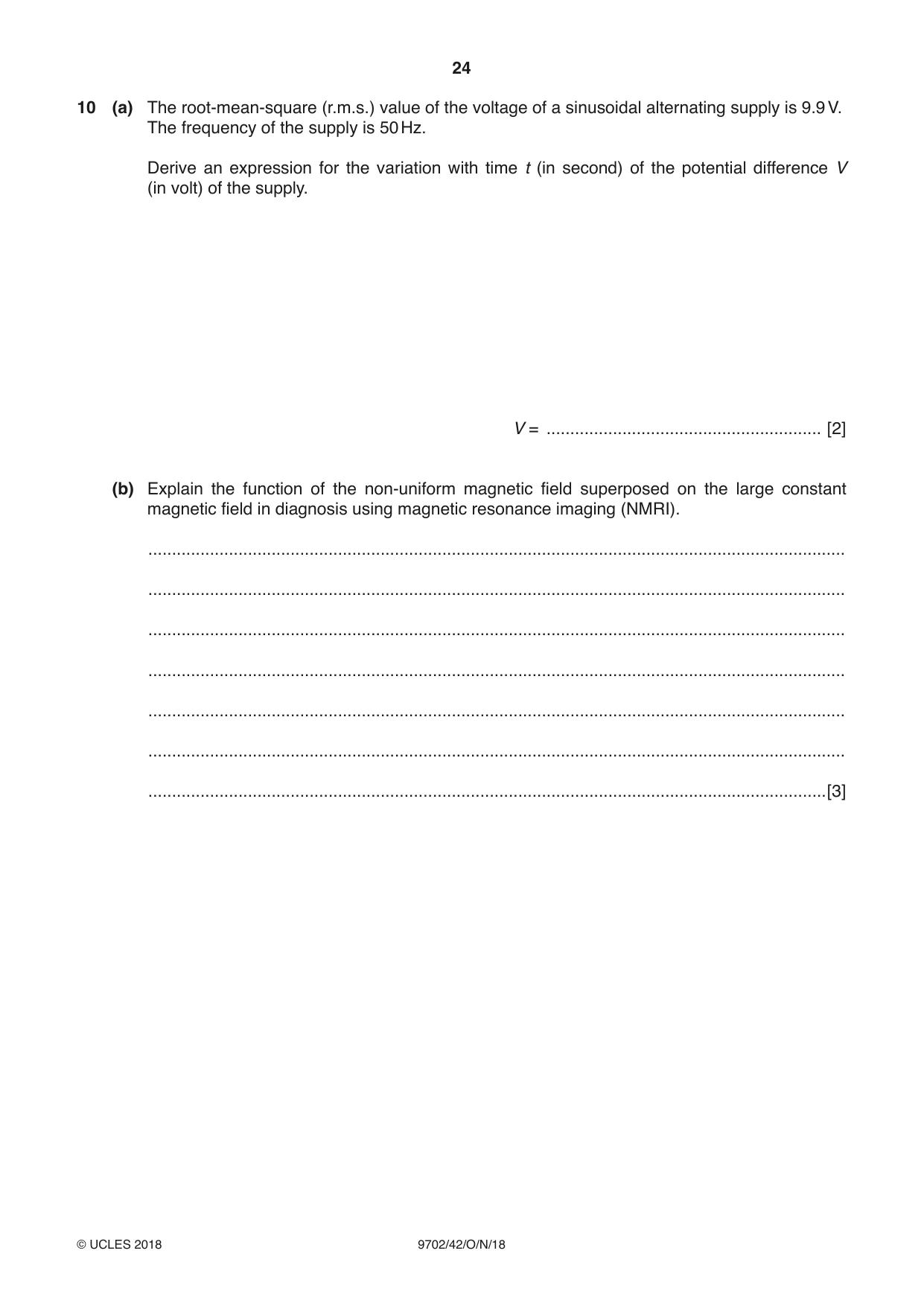
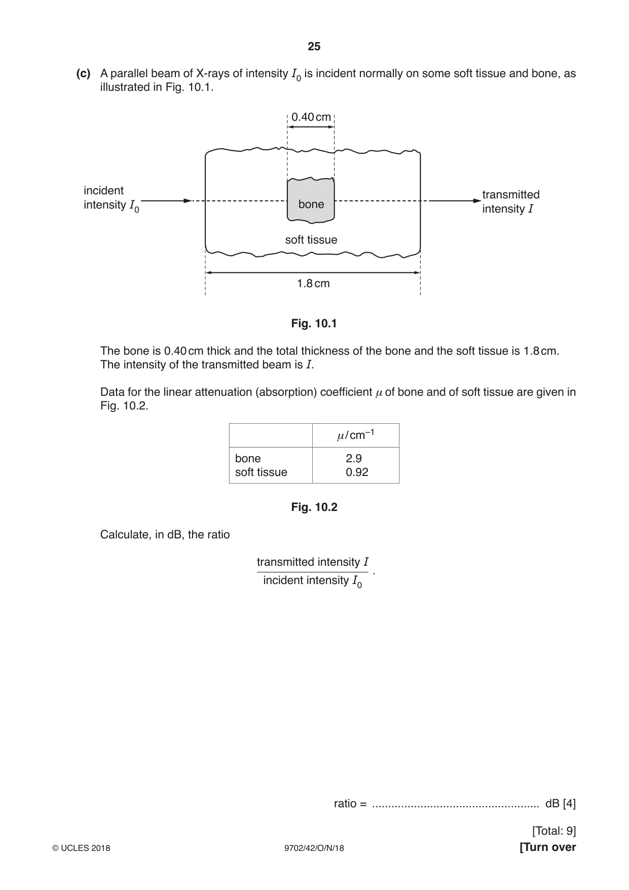
10 (a) The root-mean-square (r.m.s.) value of the voltage of a sinusoidal alternating supply is 9.9 V. The frequency of the supply is 50 Hz. Derive an expression for the variation with time t (in second) of the potential difference V (in volt) of the supply. V = .......................................................... [2] (b) Explain the function of the non-uniform magnetic field superposed on the large constant magnetic field in diagnosis using magnetic resonance imaging (NMRI). ................................................................................................................................................... ................................................................................................................................................... ................................................................................................................................................... ................................................................................................................................................... ................................................................................................................................................... ................................................................................................................................................... ...............................................................................................................................................[3] (c) A parallel beam of X-rays of intensity I0 is incident normally on some soft tissue and bone, as illustrated in Fig. 10.1. 0.40 cm incident transmitted intensity I0 bone intensity I soft tissue 1.8 cm Fig. 10.1 The bone is 0.40 cm thick and the total thickness of the bone and the soft tissue is 1.8 cm. The intensity of the transmitted beam is I. Data for the linear attenuation (absorption) coefficient μ of bone and of soft tissue are given in Fig. 10.2. μ/ cm–1 bone 2.9 soft tissue 0.92 Fig. 10.2 Calculate, in dB, the ratio transmitted intensity I . incident intensity I0 ratio = .................................................... dB [4]
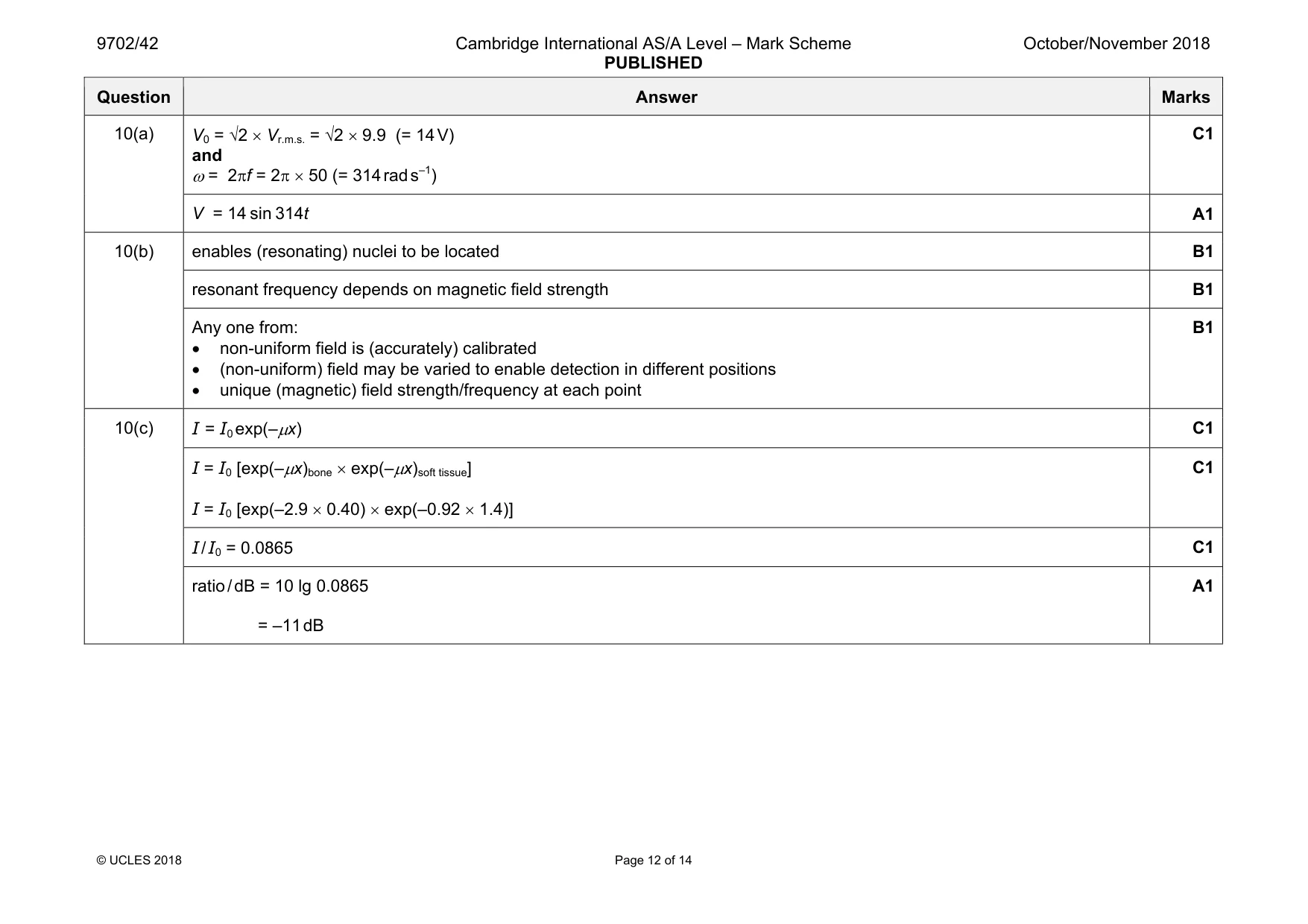
Mark scheme: 10(a) and ω = 2πf = 2π × 50 (= 314 rad s–1) C1 V = 14 sin 314t A1 10(b) enables (resonating) nuclei to be located B1 resonant frequency depends on magnetic field strength B1 Any one from: • non-uniform field is (accurately) calibrated • (non-uniform) field may be varied to enable detection in different positions • unique (magnetic) field strength/frequency at each point B1 10(c) I = I0 exp(–µx) C1 I = I0 [exp(–µx)bone × exp(–µx)soft tissue] I = I0 [exp(–2.9 × 0.40) × exp(–0.92 × 1.4)] C1 I / I0 = 0.0865 C1 ratio / dB = 10 lg 0.0865 = –11 dB A1
Q11 · State what is meant by a photon
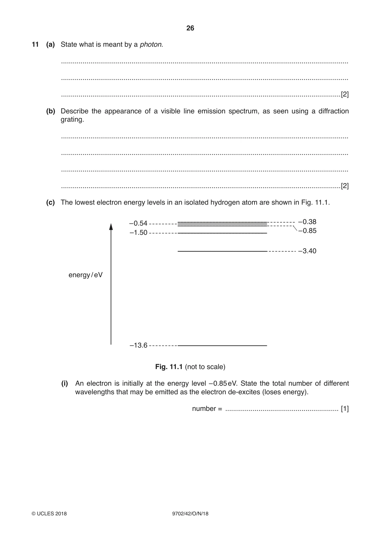
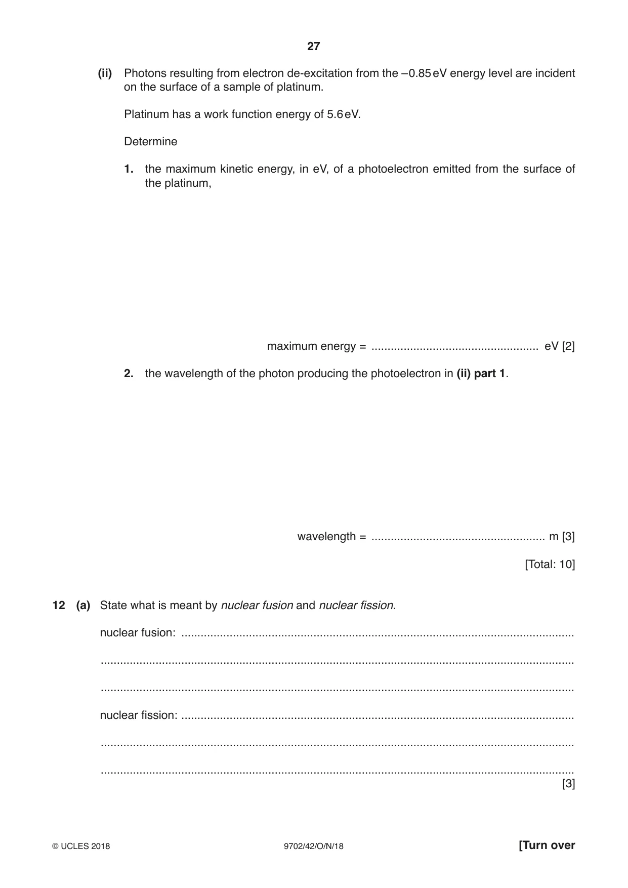
11 (a) State what is meant by a photon. ................................................................................................................................................... ................................................................................................................................................... ...............................................................................................................................................[2] (b) Describe the appearance of a visible line emission spectrum, as seen using a diffraction grating. ................................................................................................................................................... ................................................................................................................................................... ................................................................................................................................................... ...............................................................................................................................................[2] (c) The lowest electron energy levels in an isolated hydrogen atom are shown in Fig. 11.1. – 0.54 – 0.38 – 0.85 –1.50 – 3.40 energy / eV –13.6 Fig. 11.1 (not to scale) (i) An electron is initially at the energy level –0.85 eV. State the total number of different wavelengths that may be emitted as the electron de-excites (loses energy). number = .......................................................... [1] (ii) Photons resulting from electron de-excitation from the –0.85 eV energy level are incident on the surface of a sample of platinum. Platinum has a work function energy of 5.6 eV. Determine 1. the maximum kinetic energy, in eV, of a photoelectron emitted from the surface of the platinum, maximum energy = .................................................... eV [2] 2. the wavelength of the photon producing the photoelectron in (ii) part 1. wavelength = ...................................................... m [3] [Total: 10]
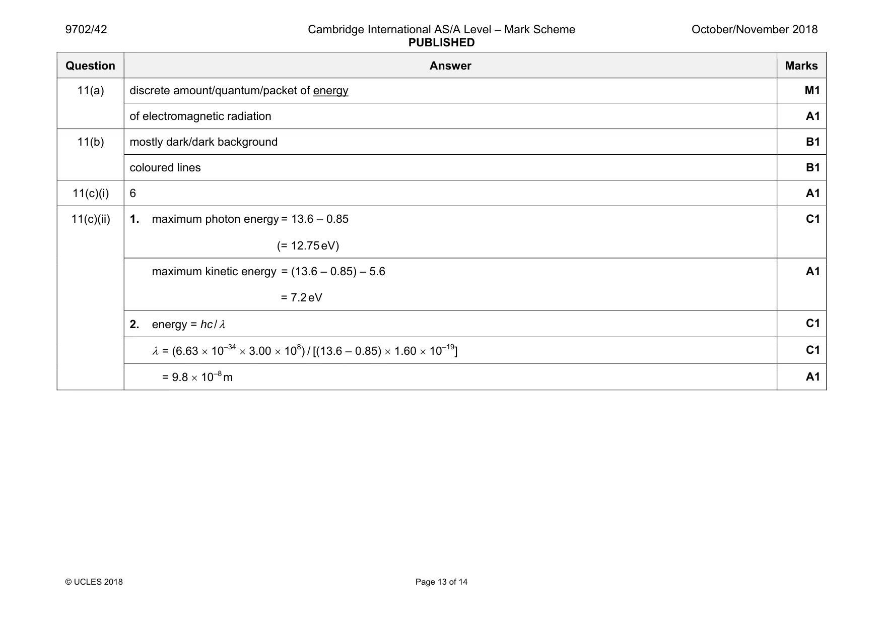
Mark scheme: 11(a) discrete amount/quantum/packet of energy M1 of electromagnetic radiation A1 11(b) mostly dark/dark background B1 coloured lines B1 11(c)(i) 6 A1 11(c)(ii) 1. maximum photon energy = 13.6 – 0.85 (= 12.75 eV) C1 maximum kinetic energy = (13.6 – 0.85) – 5.6 = 7.2 eV A1 2. energy = hc / λ C1 λ = (6.63 × 10–34 × 3.00 × 108) / [(13.6 – 0.85) × 1.60 × 10–19] C1 = 9.8 × 10⁻⁸ m A1
Q12 · State what is meant by nuclear fusion and nuclear fission
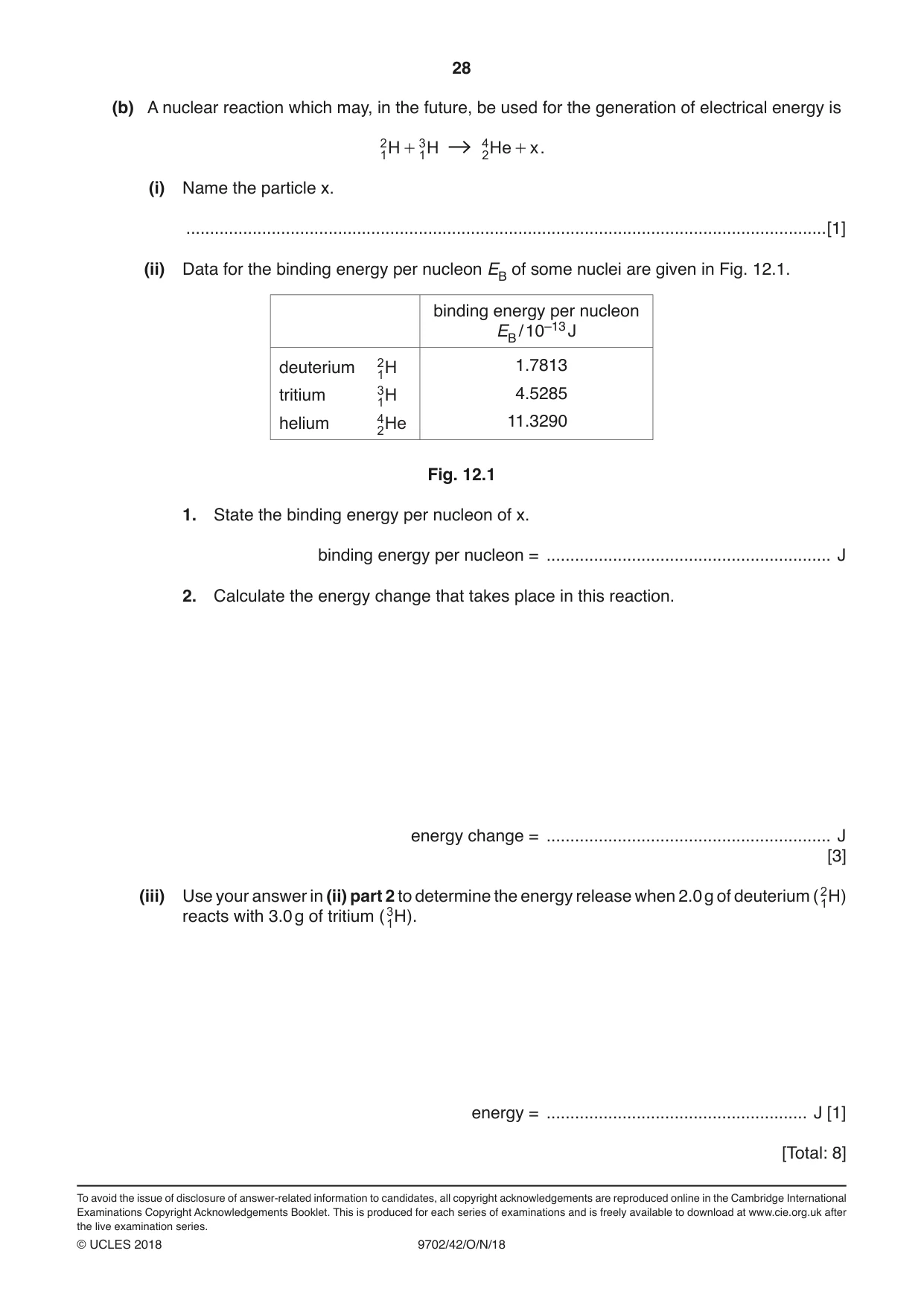
12 (a) State what is meant by nuclear fusion and nuclear fission. nuclear fusion: .......................................................................................................................... ................................................................................................................................................... ................................................................................................................................................... nuclear fission: .......................................................................................................................... ................................................................................................................................................... ................................................................................................................................................... [3] (b) A nuclear reaction which may, in the future, be used for the generation of electrical energy is 2 3 4 1 H + 1 H 2 He + x . (i) Name the particle x. .......................................................................................................................................[1] (ii) Data for the binding energy per nucleon EB of some nuclei are given in Fig. 12.1. binding energy per nucleon EB / 10–13 J deuterium 21 H 1.7813 tritium 31 H 4.5285 helium 42 He 11.3290 Fig. 12.1 1. State the binding energy per nucleon of x. binding energy per nucleon = ............................................................ J 2. Calculate the energy change that takes place in this reaction. energy change = ............................................................ J [3] (iii) Use your answer in (ii) part 2 to determine the energy release when 2.0 g of deuterium ( 21 H ) reacts with 3.0 g of tritium ( 31 H ). energy = ....................................................... J [1] [Total: 8]
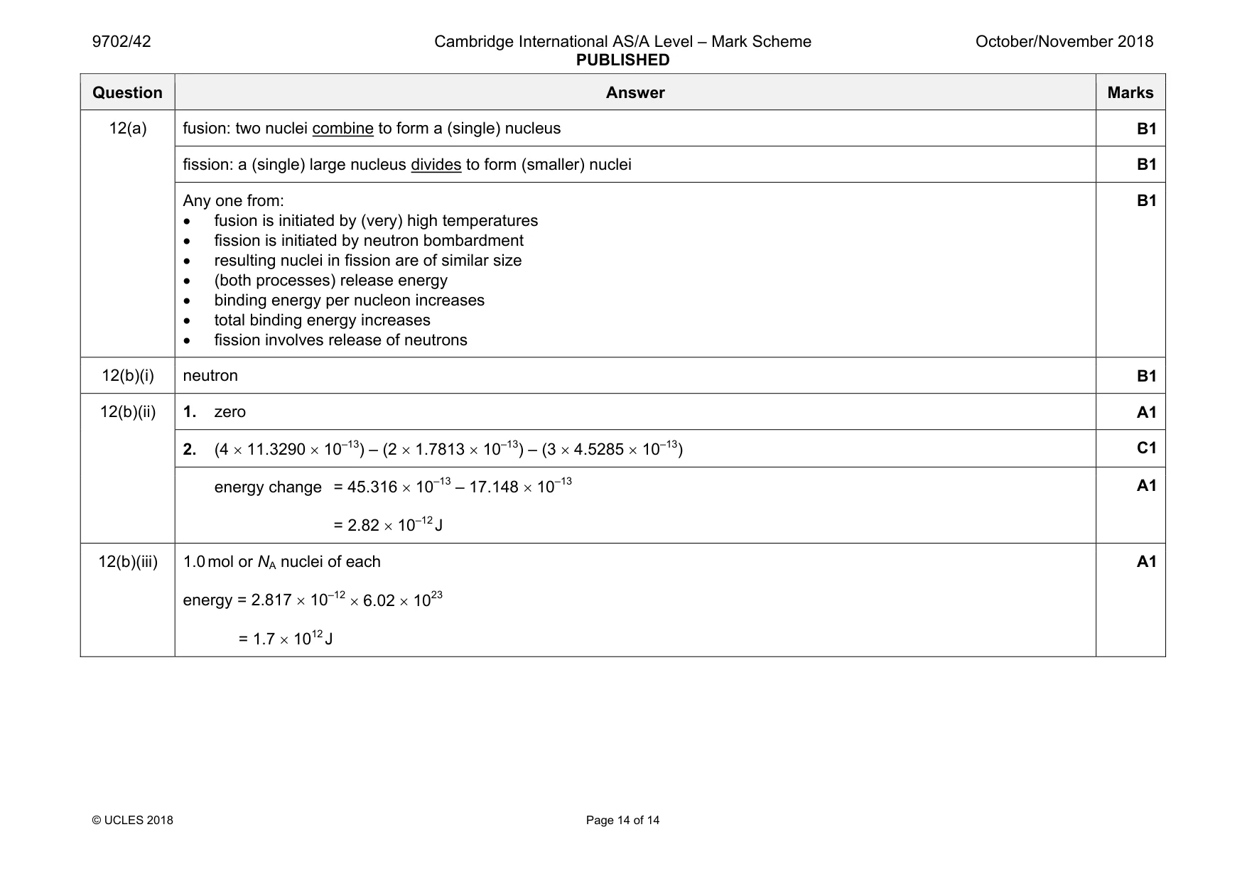
Mark scheme: 12(a) fusion: two nuclei combine to form a (single) nucleus B1 fission: a (single) large nucleus divides to form (smaller) nuclei B1 Any one from: • fusion is initiated by (very) high temperatures • fission is initiated by neutron bombardment • resulting nuclei in fission are of similar size • (both processes) release energy • binding energy per nucleon increases • total binding energy increases • fission involves release of neutrons B1 12(b)(i) neutron B1 12(b)(ii) 1. zero A1 2. (4 × 11.3290 × 10–13) – (2 × 1.7813 × 10–13) – (3 × 4.5285 × 10–13) C1 energy change = 45.316 × 10⁻¹³ – 17.148 × 10–13 = 2.82 × 10⁻¹² J A1 12(b)(iii) 1.0 mol or NA nuclei of each energy = 2.817 × 10–12 × 6.02 × 1023 = 1.7 × 10¹² J A1
What was in this paper
The subtopics covered by these 12 questions, and how many questions each got. Open one in a new tab to see every Cambridge question on it.
1Electromagnetic induction1Electromagnetic spectrum1Energy levels in atoms and line spectra1Force on a current-carrying conductor1Gravitational field of a point mass1Kinetic theory of gases1Mass defect and nuclear binding energy1Potential dividers1Production and use of X-rays1Simple harmonic oscillations1Specific heat capacity and specific latent heat1What you needed in this session
Cambridge’s own grade thresholds for 2018 Oct/Nov, Paper 4 · Variant 2. A higher threshold means an easier paper — the bar moves with how the cohort did.