Cambridge A Level Physics 9702 — 2020 Oct/Nov Paper 4 · Variant 2
9702/42/O/N/20 · 12 questions · 100 marks · ≈113 min
The question paper and its mark scheme, free to read here and free to download. This is Cambridge’s own paper, exactly as it was sat.
Question paper24 pages
Mark scheme16 pages
Answers below. Sit the paper first if you are practising.
Questions as text
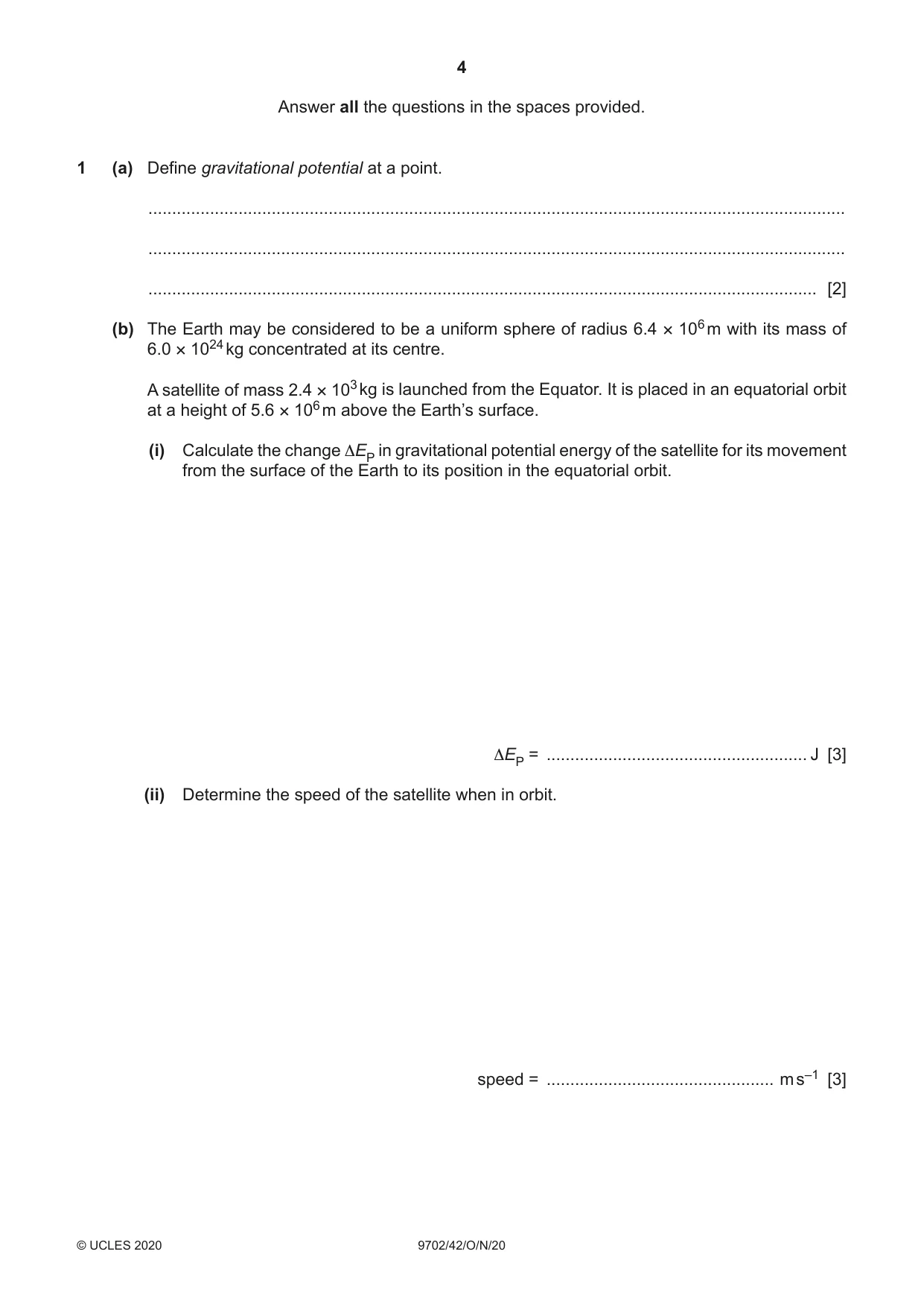
Q1 · Define gravitational potential at a point
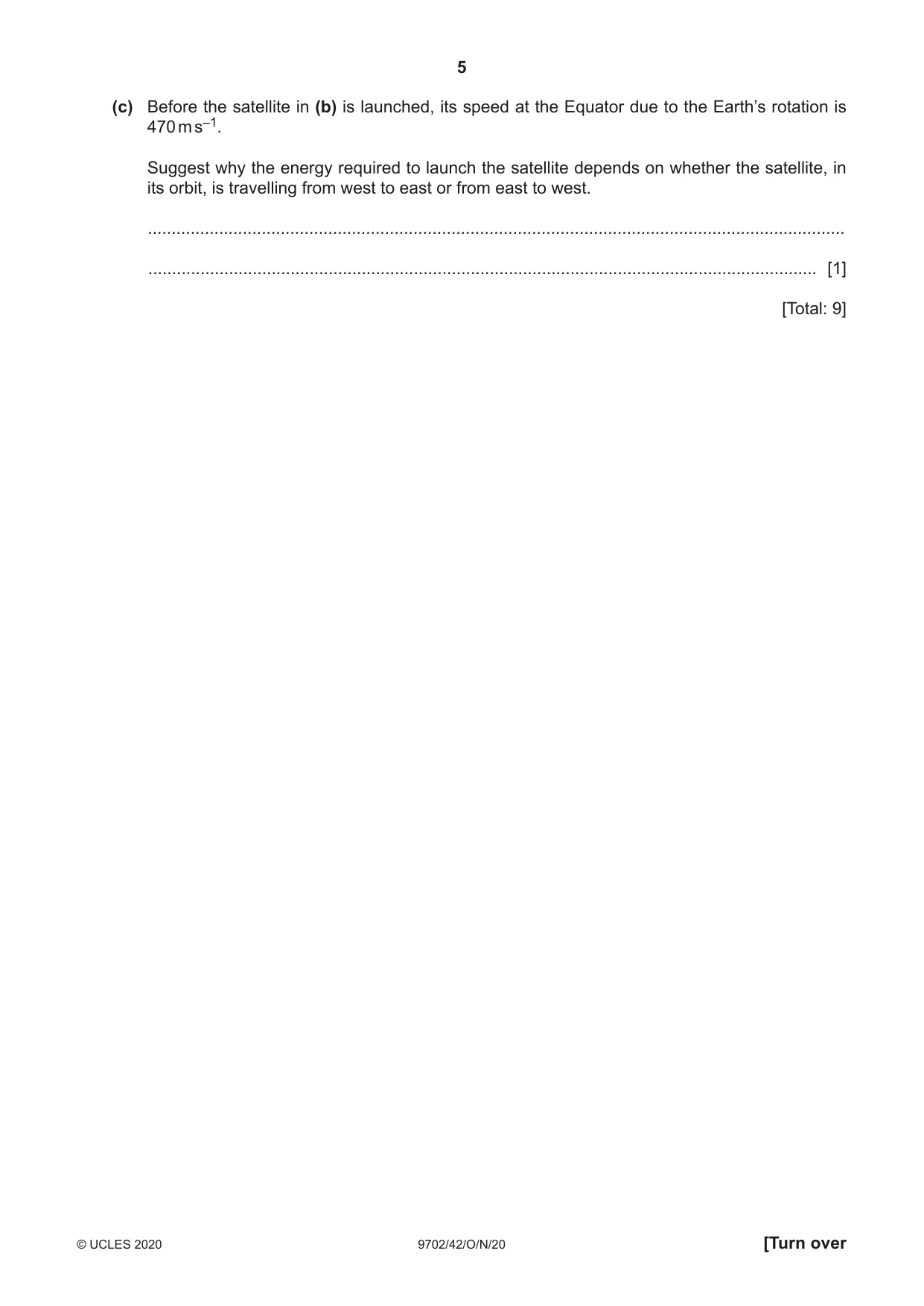
1 (a) Define gravitational potential at a point. ................................................................................................................................................... ................................................................................................................................................... ............................................................................................................................................. [2] (b) The Earth may be considered to be a uniform sphere of radius 6.4 × 10⁶ m with its mass of 6.0 × 1024 kg concentrated at its centre. A satellite of mass 2.4 × 10³ kg is launched from the Equator. It is placed in an equatorial orbit at a height of 5.6 × 10⁶ m above the Earth’s surface. (i) Calculate the change ΔEP in gravitational potential energy of the satellite for its movement from the surface of the Earth to its position in the equatorial orbit. ΔEP = ....................................................... J [3] (ii) Determine the speed of the satellite when in orbit. speed = ................................................ m s–1 [3] (c) Before the satellite in (b) is launched, its speed at the Equator due to the Earth’s rotation is 470 m s–1. Suggest why the energy required to launch the satellite depends on whether the satellite, in its orbit, is travelling from west to east or from east to west. ................................................................................................................................................... ............................................................................................................................................. [1] [Total: 9]
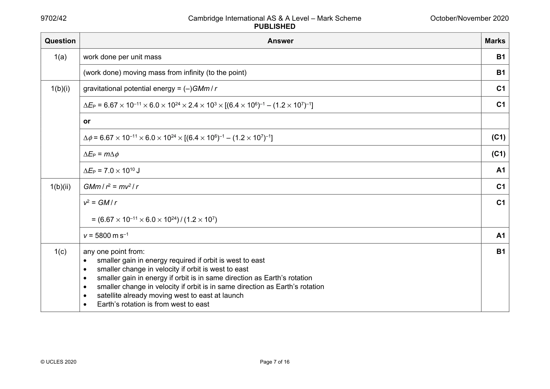
Mark scheme: 1(a) work done per unit mass B1 (work done) moving mass from infinity (to the point) B1 1(b)(i) gravitational potential energy = (–)GMm / r C1 ΔEP = 6.67 × 10–11 × 6.0 × 1024 × 2.4 × 103 × [(6.4 × 10⁶)–1 – (1.2 × 10⁷)–1] C1 or Δφ = 6.67 × 10–11 × 6.0 × 1024 × [(6.4 × 10⁶)–1 – (1.2 × 10⁷)–1] (C1) ΔEP = mΔφ (C1) ΔEP = 7.0 × 10¹⁰ J A1 1(b)(ii) GMm / r2 = mv2 / r C1 v2 = GM / r = (6.67 × 10–11 × 6.0 × 1024) / (1.2 × 10⁷) C1 v = 5800 m s–1 A1 1(c) any one point from: • smaller gain in energy required if orbit is west to east • smaller change in velocity if orbit is west to east • smaller gain in energy if orbit is in same direction as Earth’s rotation • smaller change in velocity if orbit is in same direction as Earth’s rotation • satellite already moving west to east at launch • Earth’s rotation is from west to east B1
Q2 · State what is meant by the internal energy of a system
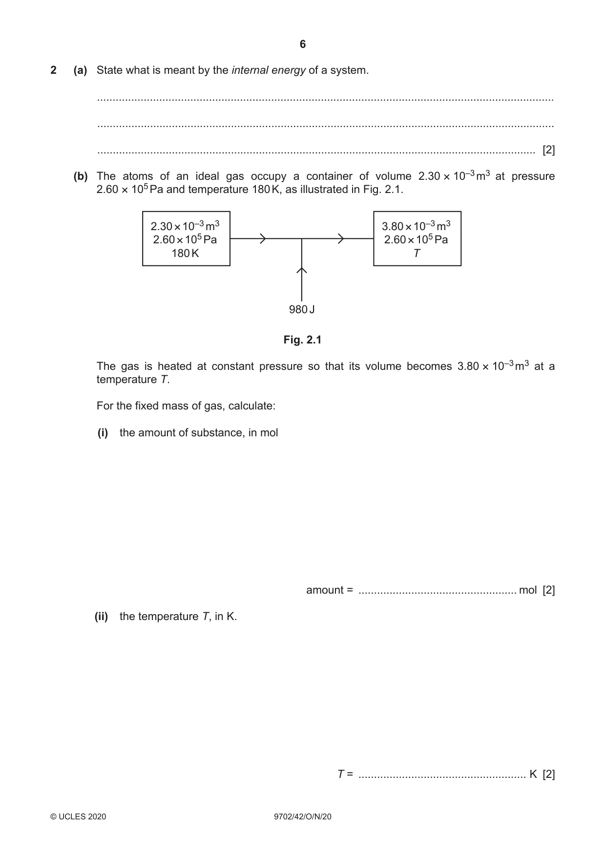
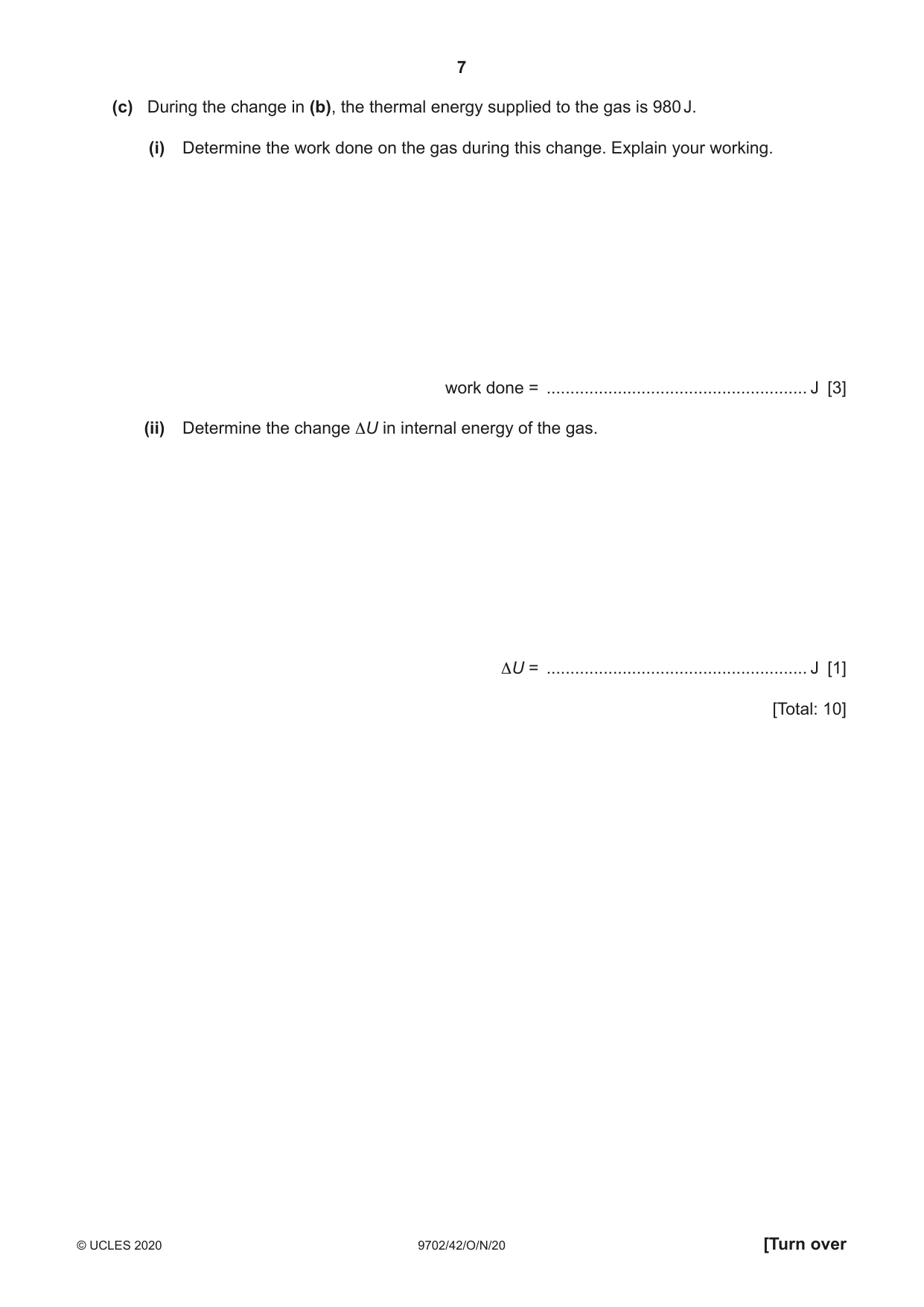
2 (a) State what is meant by the internal energy of a system. ................................................................................................................................................... ................................................................................................................................................... ............................................................................................................................................. [2] (b) The atoms of an ideal gas occupy a container of volume 2.30 × 10⁻³ m3 at pressure 2.60 × 10⁵ Pa and temperature 180 K, as illustrated in Fig. 2.1. 2.30 × 10⁻³ m3 3.80 × 10⁻³ m3 2.60 × 10⁵ Pa 2.60 × 10⁵ Pa 180 K T 980 J Fig. 2.1 The gas is heated at constant pressure so that its volume becomes 3.80 × 10⁻³ m3 at a temperature T. For the fixed mass of gas, calculate: (i) the amount of substance, in mol amount = ................................................... mol [2] (ii) the temperature T, in K. T = ...................................................... K [2] (c) During the change in (b), the thermal energy supplied to the gas is 980 J. (i) Determine the work done on the gas during this change. Explain your working. work done = ....................................................... J [3] (ii) Determine the change ΔU in internal energy of the gas. ΔU = ....................................................... J [1] [Total: 10]
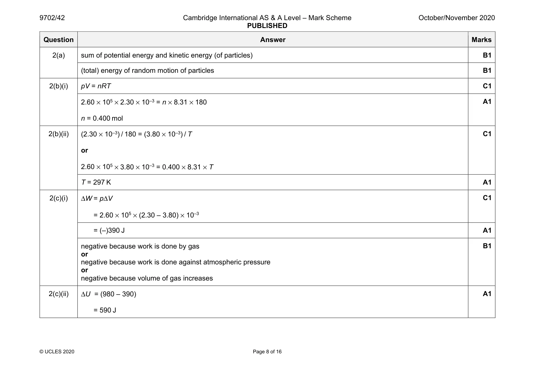
Mark scheme: 2(a) sum of potential energy and kinetic energy (of particles) B1 (total) energy of random motion of particles B1 2(b)(i) pV = nRT C1 2.60 × 105 × 2.30 × 10–3 = n × 8.31 × 180 n = 0.400 mol A1 2(b)(ii) (2.30 × 10⁻³) / 180 = (3.80 × 10⁻³) / T or 2.60 × 105 × 3.80 × 10–3 = 0.400 × 8.31 × T C1 T = 297 K A1 2(c)(i) ΔW = pΔV = 2.60 × 105 × (2.30 – 3.80) × 10–3 C1 = (–)390 J A1 negative because work is done by gas or negative because work is done against atmospheric pressure or negative because volume of gas increases B1 2(c)(ii) ΔU = (980 – 390) = 590 J A1
Q3 · A simple pendulum consists of a metal sphere suspended from a fixed point by means of a…
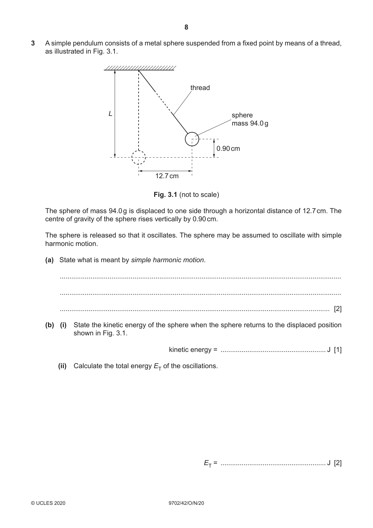
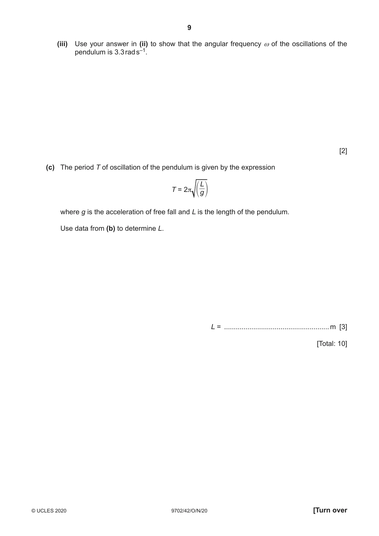
3 A simple pendulum consists of a metal sphere suspended from a fixed point by means of a thread, as illustrated in Fig. 3.1. thread L sphere mass 94.0 g 0.90 cm 12.7 cm Fig. 3.1 (not to scale) The sphere of mass 94.0 g is displaced to one side through a horizontal distance of 12.7 cm. The centre of gravity of the sphere rises vertically by 0.90 cm. The sphere is released so that it oscillates. The sphere may be assumed to oscillate with simple harmonic motion. (a) State what is meant by simple harmonic motion. ................................................................................................................................................... ................................................................................................................................................... ............................................................................................................................................. [2] (b) (i) State the kinetic energy of the sphere when the sphere returns to the displaced position shown in Fig. 3.1. kinetic energy = ....................................................... J [1] (ii) Calculate the total energy ET of the oscillations. ET = ....................................................... J [2] (iii) Use your answer in (ii) to show that the angular frequency ω of the oscillations of the pendulum is 3.3 rad s–1. [2] (c) The period T of oscillation of the pendulum is given by the expression L T = 2π g where g is the acceleration of free fall and L is the length of the pendulum. Use data from (b) to determine L. L = ...................................................... m [3] [Total: 10]
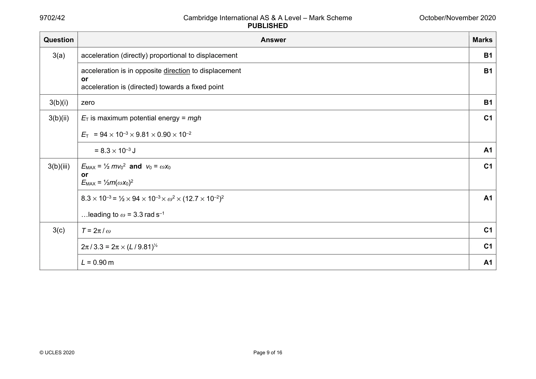
Mark scheme: 3(a) acceleration (directly) proportional to displacement B1 acceleration is in opposite direction to displacement or acceleration is (directed) towards a fixed point B1 3(b)(i) zero B1 3(b)(ii) ET is maximum potential energy = mgh ET = 94 × 10–3 × 9.81 × 0.90 × 10–2 C1 = 8.3 × 10⁻³ J A1 3(b)(iii) EMAX = ½ mv02 and v0 = ωx0 or EMAX = ½m(ωx0)2 C1 8.3 × 10–3 = ½ × 94 × 10–3 × ω2 × (12.7 × 10–2)2 …leading to ω = 3.3 rad s–1 A1 3(c) T = 2π / ω C1 2π / 3.3 = 2π × (L / 9.81)½ C1 L = 0.90 m A1
Q4 · State two advantages of the transmission of data in digital, rather than analogue, form
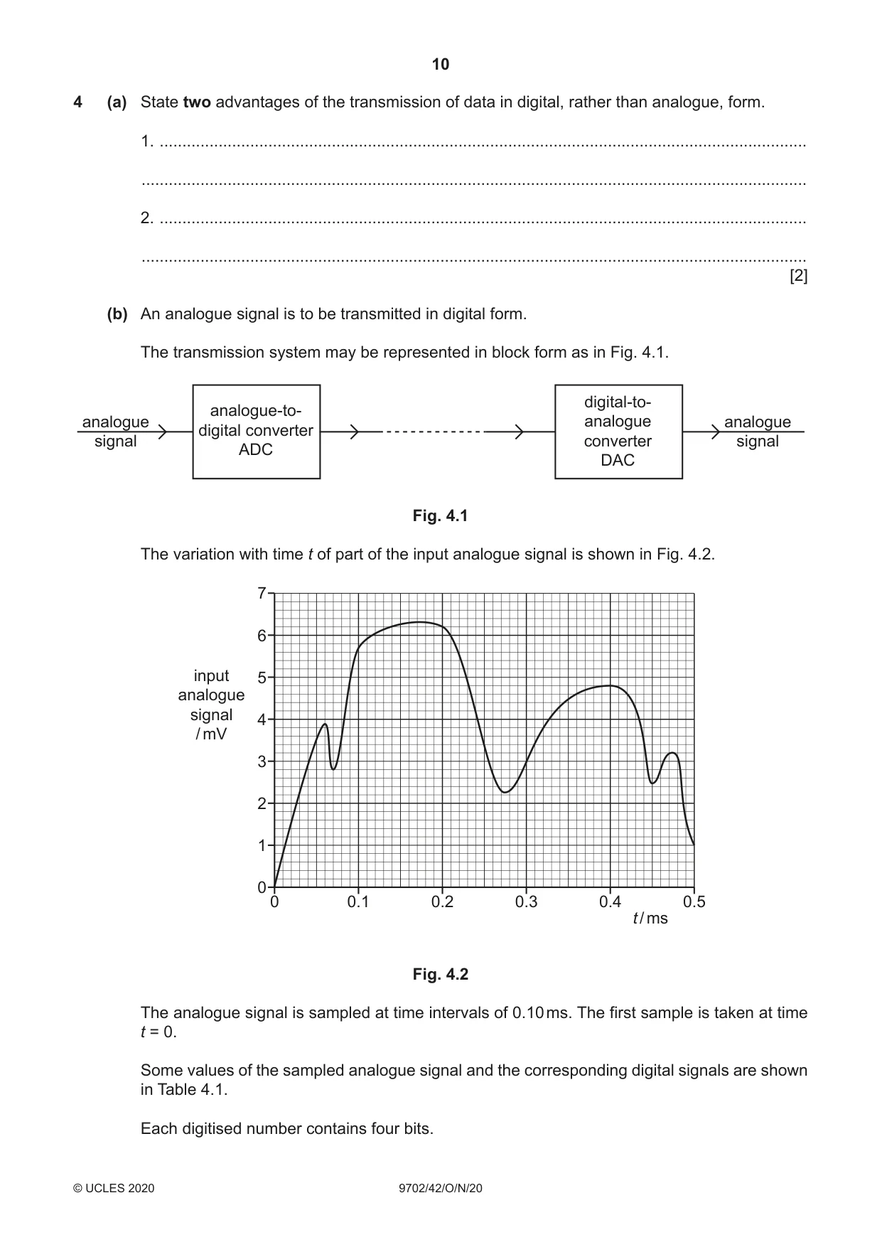
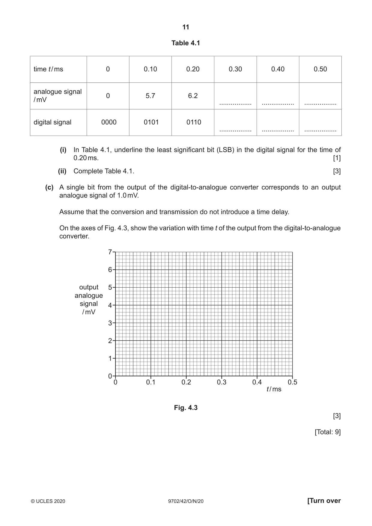
4 (a) State two advantages of the transmission of data in digital, rather than analogue, form. 1. ............................................................................................................................................... ................................................................................................................................................... 2. ............................................................................................................................................... ................................................................................................................................................... [2] (b) An analogue signal is to be transmitted in digital form. The transmission system may be represented in block form as in Fig. 4.1. digital-to- analogue-to- analogue analogue analogue digital converter signal converter signal ADC DAC Fig. 4.1 The variation with time t of part of the input analogue signal is shown in Fig. 4.2. 7 6 input 5 analogue signal 4 / mV 3 2 1 0 0 0.1 0.2 0.3 0.4 0.5 t / ms Fig. 4.2 The analogue signal is sampled at time intervals of 0.10 ms. The first sample is taken at time t = 0. Some values of the sampled analogue signal and the corresponding digital signals are shown in Table 4.1. Each digitised number contains four bits. Table 4.1 time t / ms 0 0.10 0.20 0.30 0.40 0.50 analogue signal 0 5.7 6.2/ mV ................. ................. ................. digital signal 0000 0101 0110 ................. ................. ................. (i) In Table 4.1, underline the least significant bit (LSB) in the digital signal for the time of 0.20 ms. [1] (ii) Complete Table 4.1. [3] (c) A single bit from the output of the digital-to-analogue converter corresponds to an output analogue signal of 1.0 mV. Assume that the conversion and transmission do not introduce a time delay. On the axes of Fig. 4.3, show the variation with time t of the output from the digital-to-analogue converter. 7 6 output 5 analogue signal 4 / mV 3 2 1 0 0 0.1 0.2 0.3 0.4 0.5 t / ms Fig. 4.3 [3] [Total: 9]
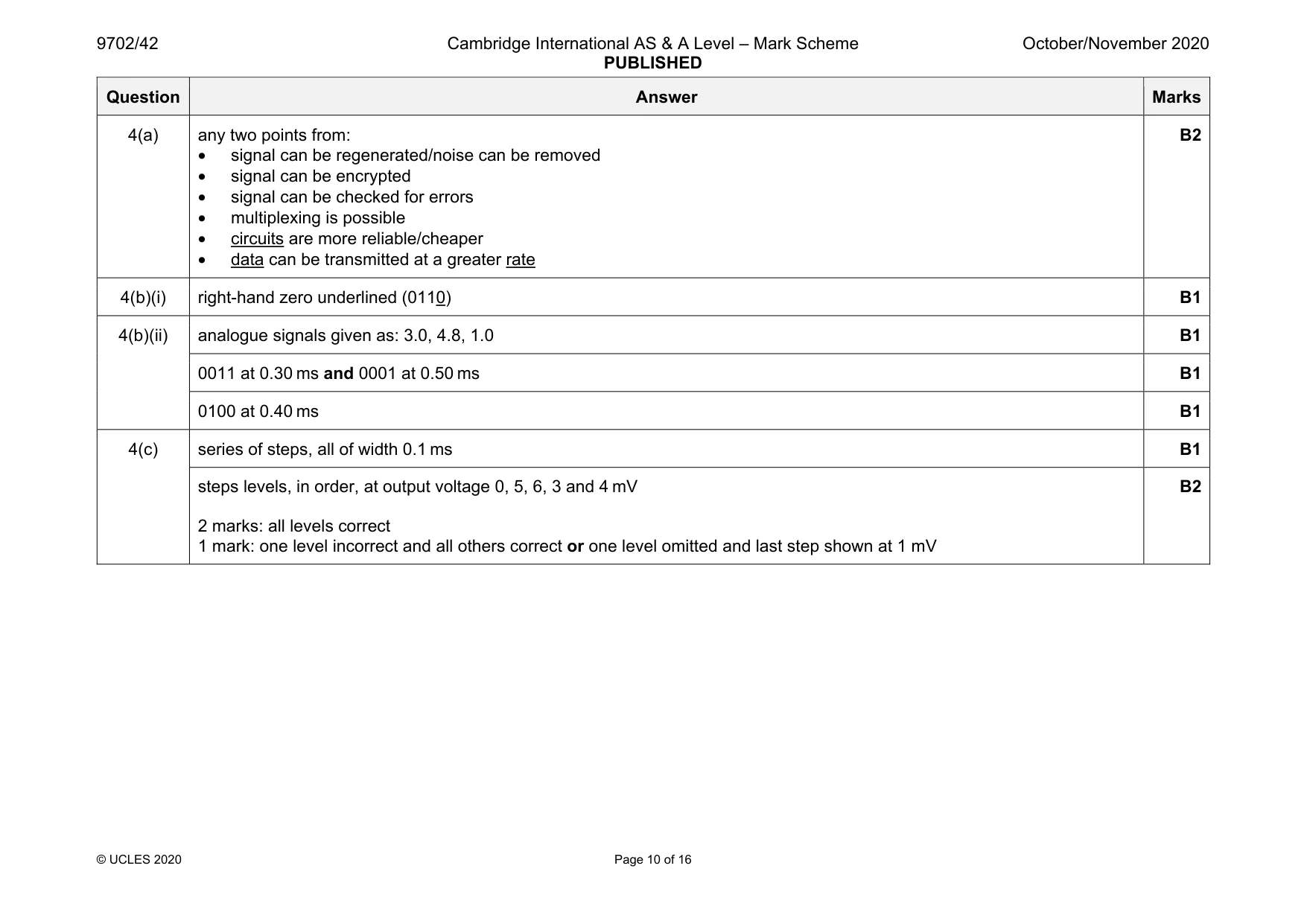
Mark scheme: 4(a) any two points from: • signal can be regenerated/noise can be removed • signal can be encrypted • signal can be checked for errors • multiplexing is possible • circuits are more reliable/cheaper • data can be transmitted at a greater rate B2 4(b)(i) right-hand zero underlined (0110) B1 4(b)(ii) analogue signals given as: 3.0, 4.8, 1.0 B1 0011 at 0.30 ms and 0001 at 0.50 ms B1 0100 at 0.40 ms B1 4(c) series of steps, all of width 0.1 ms B1 steps levels, in order, at output voltage 0, 5, 6, 3 and 4 mV 2 marks: all levels correct 1 mark: one level incorrect and all others correct or one level omitted and last step shown at 1 mV B2
Q5 · State what is meant by a field of force
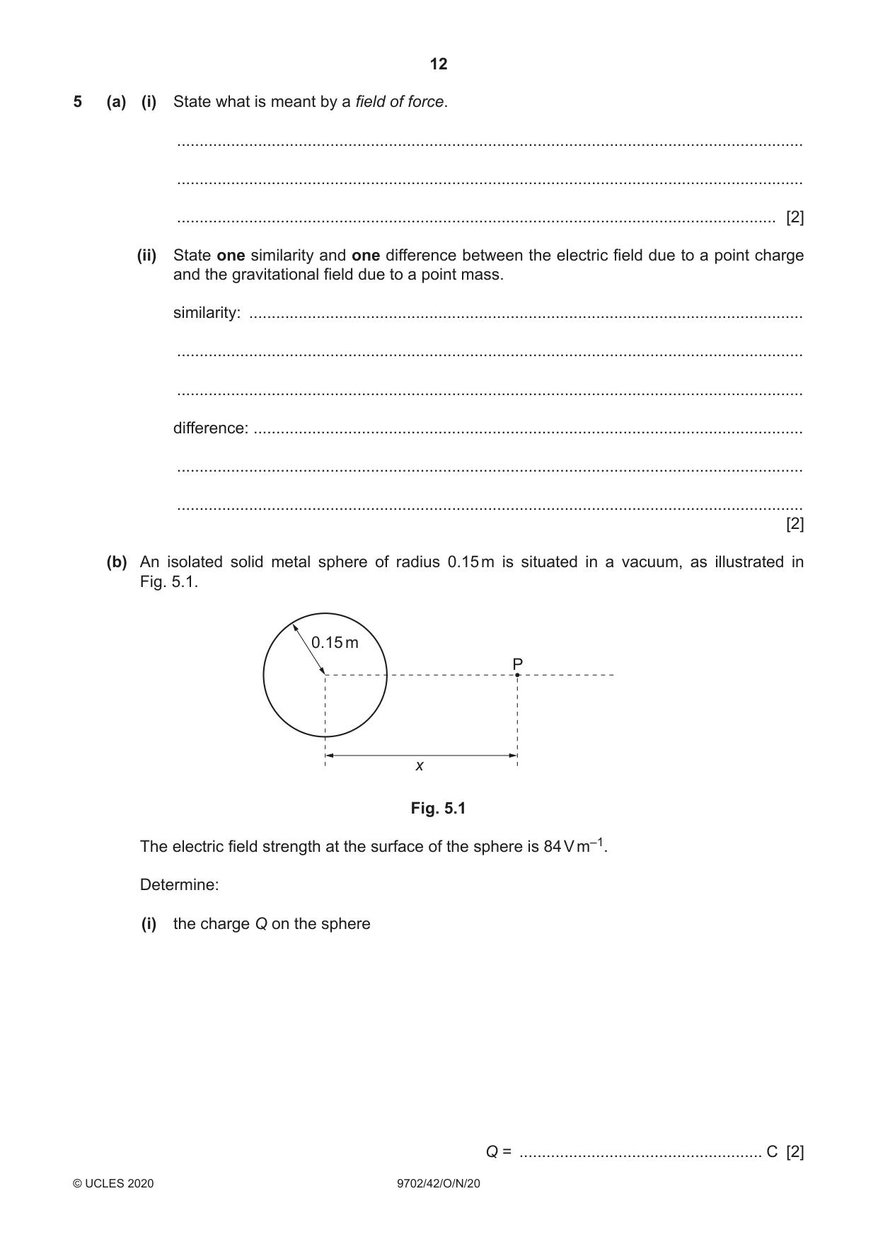
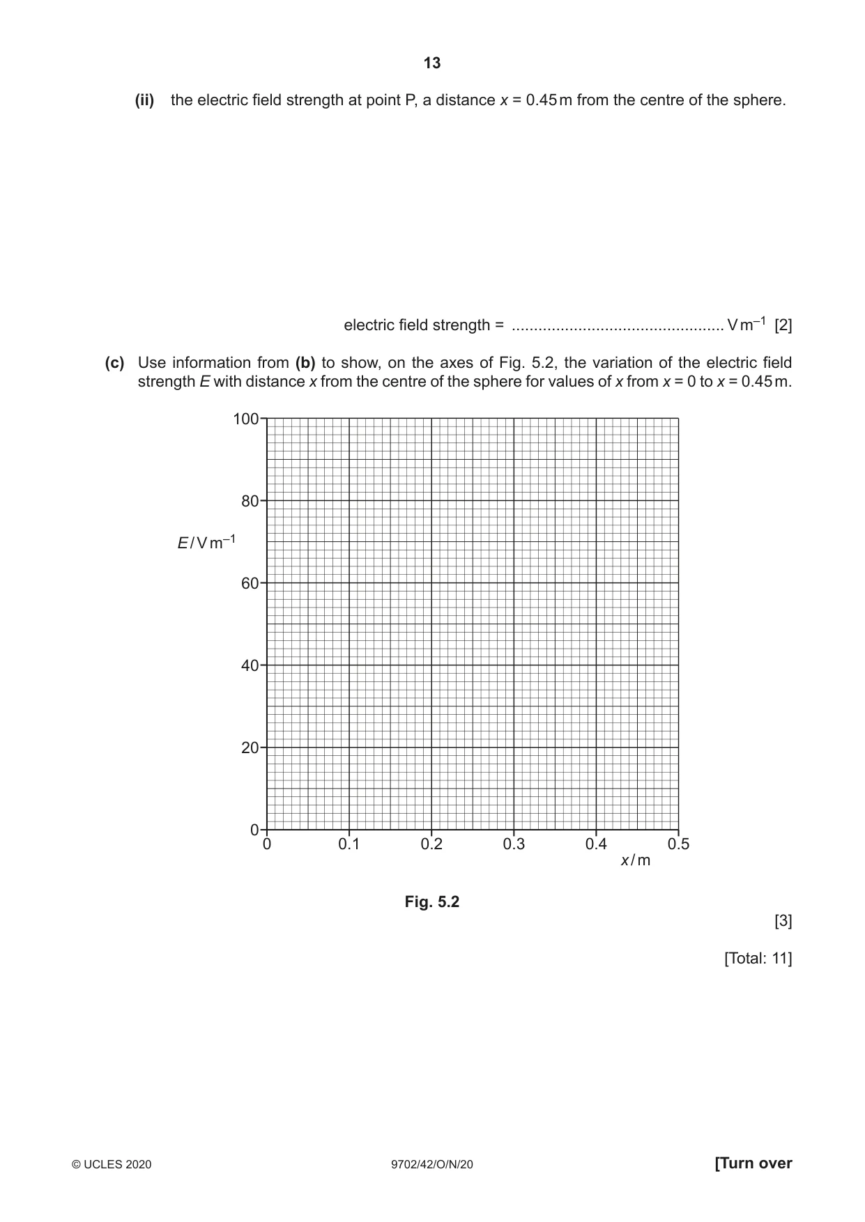
5 (a) (i) State what is meant by a field of force. ........................................................................................................................................... ........................................................................................................................................... ..................................................................................................................................... [2] (ii) State one similarity and one difference between the electric field due to a point charge and the gravitational field due to a point mass. similarity: ........................................................................................................................... ........................................................................................................................................... ........................................................................................................................................... difference: .......................................................................................................................... ........................................................................................................................................... ........................................................................................................................................... [2] (b) An isolated solid metal sphere of radius 0.15 m is situated in a vacuum, as illustrated in Fig. 5.1. 0.15 m P x Fig. 5.1 The electric field strength at the surface of the sphere is 84 V m–1. Determine: (i) the charge Q on the sphere Q = ...................................................... C [2] (ii) the electric field strength at point P, a distance x = 0.45 m from the centre of the sphere. electric field strength = ................................................ V m–1 [2] (c) Use information from (b) to show, on the axes of Fig. 5.2, the variation of the electric field strength E with distance x from the centre of the sphere for values of x from x = 0 to x = 0.45 m. 100 80 E / V m–1 60 40 20 0 0 0.1 0.2 0.3 0.4 0.5 x / m Fig. 5.2 [3] [Total: 11]
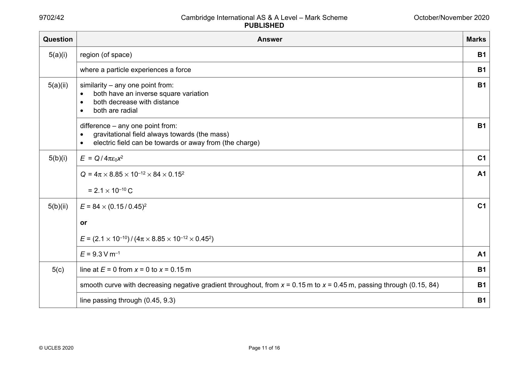
Mark scheme: 5(a)(i) region (of space) B1 where a particle experiences a force B1 5(a)(ii) similarity – any one point from: • both have an inverse square variation • both decrease with distance • both are radial B1 difference – any one point from: • gravitational field always towards (the mass) • electric field can be towards or away from (the charge) B1 5(b)(i) E = Q / 4πε0x2 C1 Q = 4π × 8.85 × 10–12 × 84 × 0.152 = 2.1 × 10⁻¹⁰ C A1 5(b)(ii) E = 84 × (0.15 / 0.45)2 or E = (2.1 × 10⁻¹⁰) / (4π × 8.85 × 10–12 × 0.452) C1 E = 9.3 V m–1 A1 5(c) line at E = 0 from x = 0 to x = 0.15 m B1 smooth curve with decreasing negative gradient throughout, from x = 0.15 m to x = 0.45 m, passing through (0.15, 84) B1 line passing through (0.45, 9.3) B1
Q6 · Define the capacitance of a parallel plate capacitor
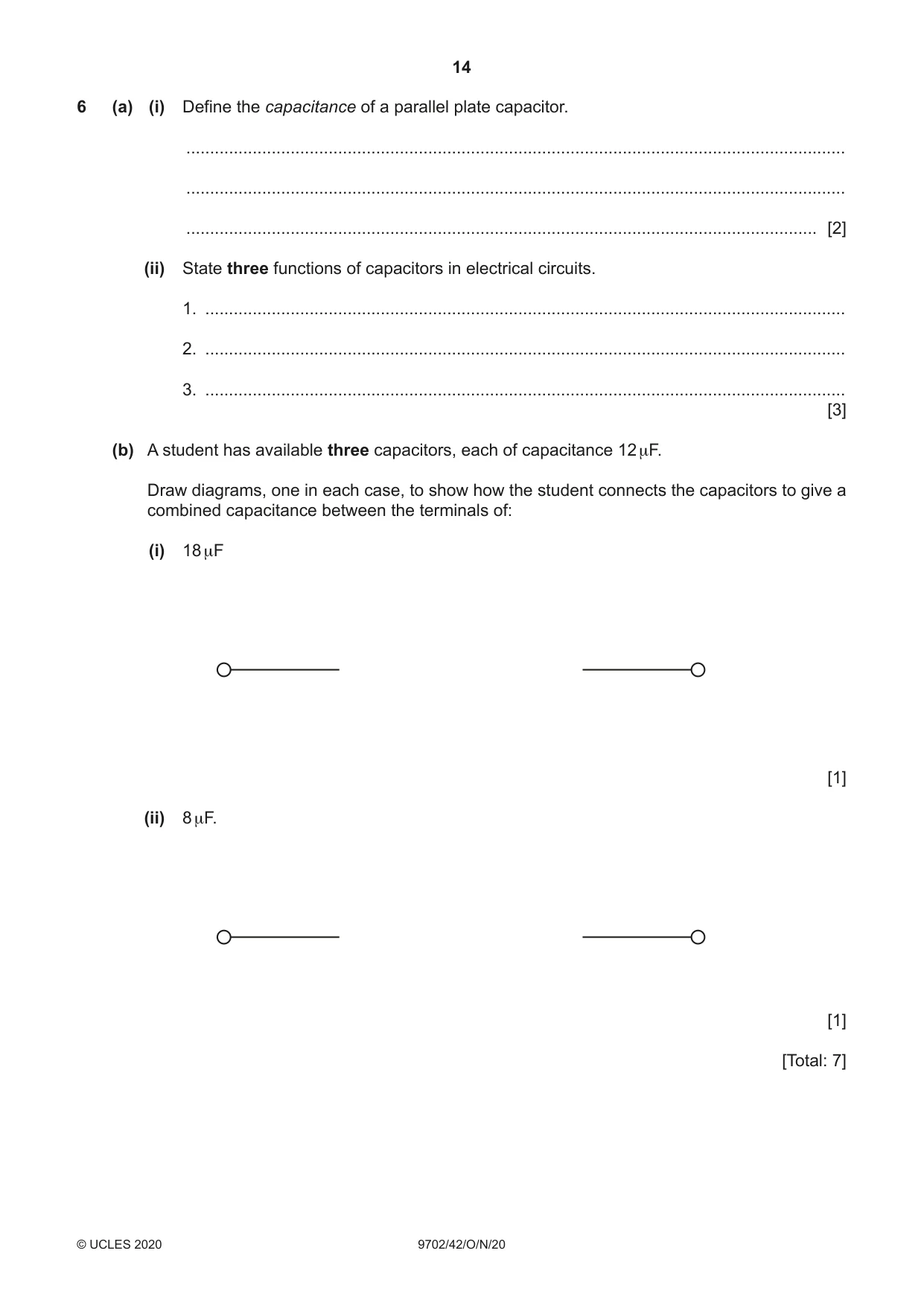
6 (a) (i) Define the capacitance of a parallel plate capacitor. ........................................................................................................................................... ........................................................................................................................................... ..................................................................................................................................... [2] (ii) State three functions of capacitors in electrical circuits. 1. ....................................................................................................................................... 2. ....................................................................................................................................... 3. ....................................................................................................................................... [3] (b) A student has available three capacitors, each of capacitance 12 μF. Draw diagrams, one in each case, to show how the student connects the capacitors to give a combined capacitance between the terminals of: (i) 18 μF [1] (ii) 8 μF. [1] [Total: 7]
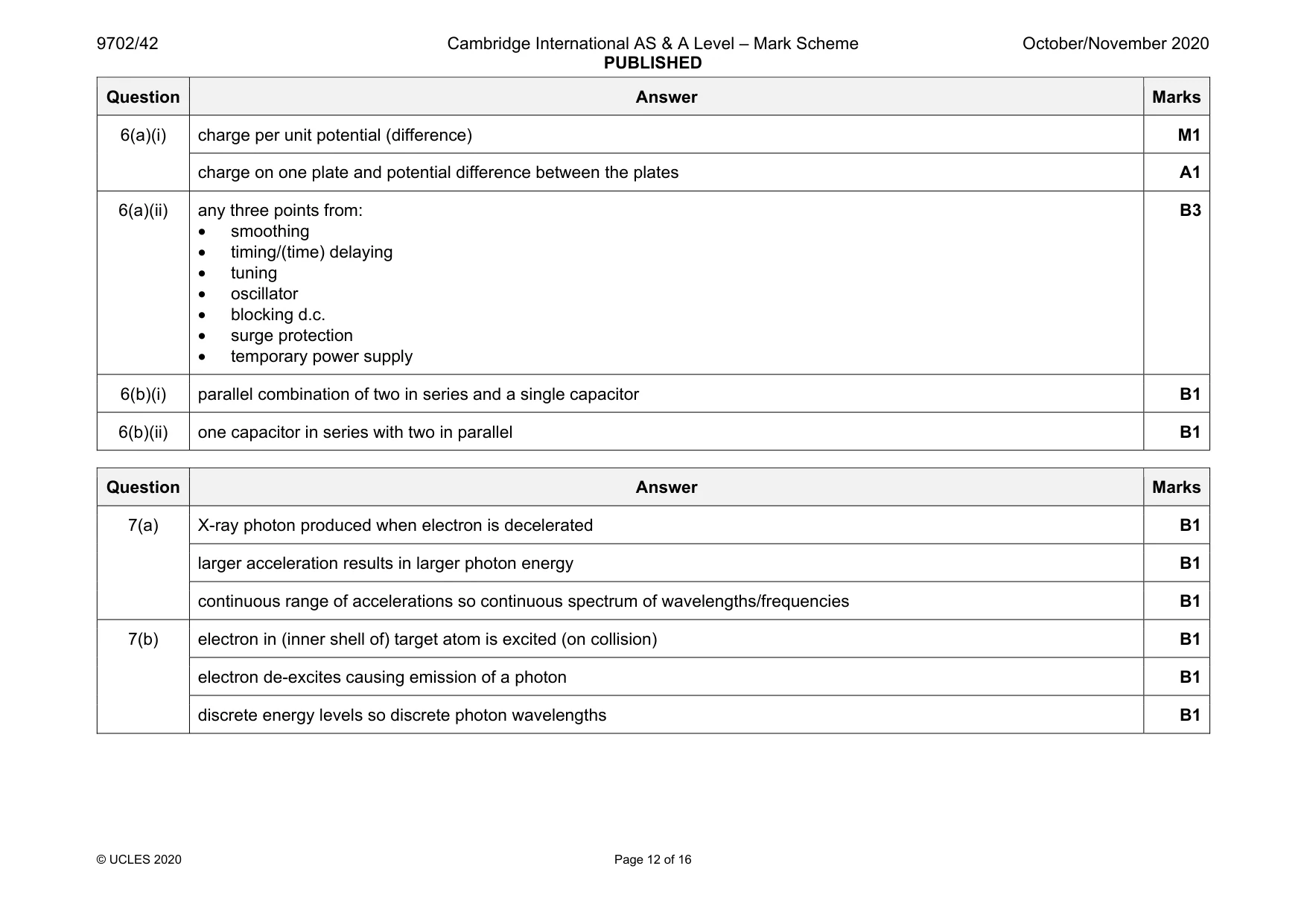
Mark scheme: 6(a)(i) charge per unit potential (difference) M1 charge on one plate and potential difference between the plates A1 6(a)(ii) any three points from: • smoothing • timing/(time) delaying • tuning • oscillator • blocking d.c. • surge protection • temporary power supply B3 6(b)(i) parallel combination of two in series and a single capacitor B1 6(b)(ii) one capacitor in series with two in parallel B1
Q7 · Electrons in a beam are travelling at high speed in a vacuum
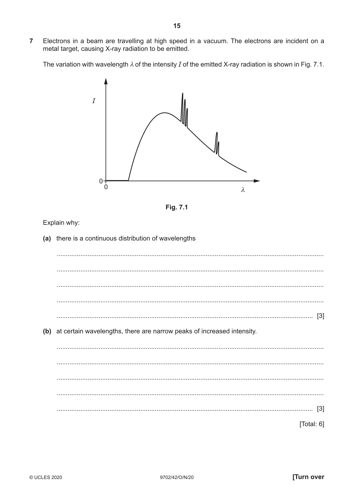
7 Electrons in a beam are travelling at high speed in a vacuum. The electrons are incident on a metal target, causing X-ray radiation to be emitted. The variation with wavelength λ of the intensity I of the emitted X-ray radiation is shown in Fig. 7.1. I 0 0 λ Fig. 7.1 Explain why: (a) there is a continuous distribution of wavelengths ................................................................................................................................................... ................................................................................................................................................... ................................................................................................................................................... ................................................................................................................................................... ............................................................................................................................................. [3] (b) at certain wavelengths, there are narrow peaks of increased intensity. ................................................................................................................................................... ................................................................................................................................................... ................................................................................................................................................... ................................................................................................................................................... ............................................................................................................................................. [3] [Total: 6]
Mark scheme: 7(a) X-ray photon produced when electron is decelerated B1 larger acceleration results in larger photon energy B1 continuous range of accelerations so continuous spectrum of wavelengths/frequencies B1 7(b) electron in (inner shell of) target atom is excited (on collision) B1 electron de-excites causing emission of a photon B1 discrete energy levels so discrete photon wavelengths B1
Q8 · An ideal operational amplifier (op-amp) is said to have infinite bandwidth and infinite…
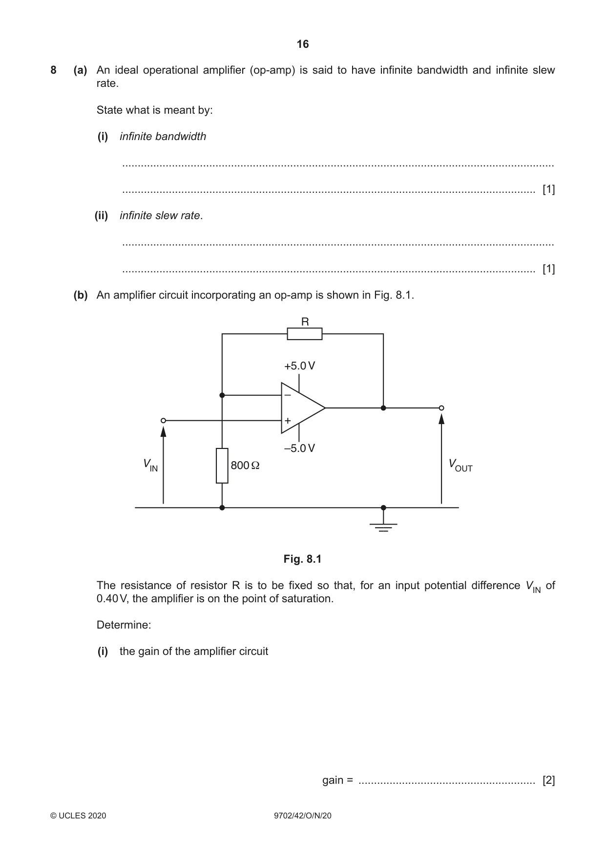
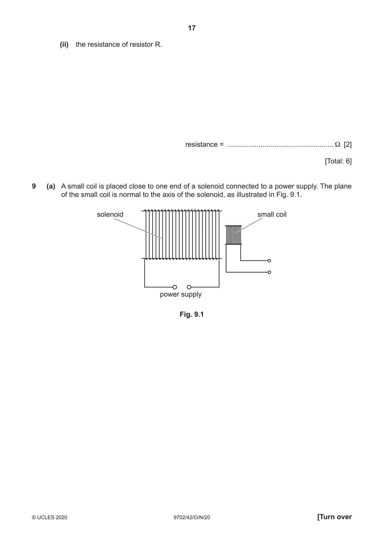
8 (a) An ideal operational amplifier (op-amp) is said to have infinite bandwidth and infinite slew rate. State what is meant by: (i) infinite bandwidth ........................................................................................................................................... ..................................................................................................................................... [1] (ii) infinite slew rate. ........................................................................................................................................... ..................................................................................................................................... [1] (b) An amplifier circuit incorporating an op-amp is shown in Fig. 8.1. R +5.0 V – + –5.0 V VIN 800 Ω VOUT Fig. 8.1 The resistance of resistor R is to be fixed so that, for an input potential difference VIN of 0.40 V, the amplifier is on the point of saturation. Determine: (i) the gain of the amplifier circuit gain = ......................................................... [2] (ii) the resistance of resistor R. resistance = ...................................................... Ω [2] [Total: 6]
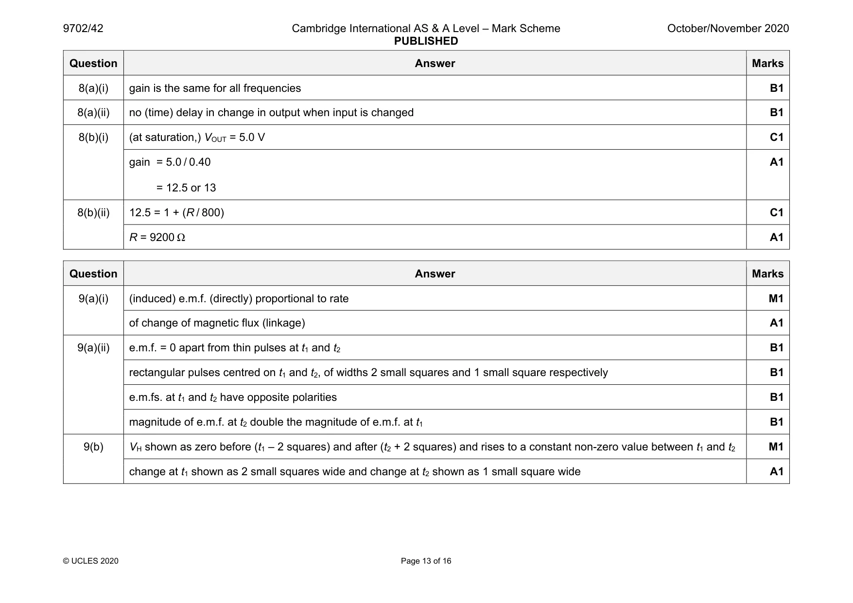
Mark scheme: 8(a)(i) gain is the same for all frequencies B1 8(a)(ii) no (time) delay in change in output when input is changed B1 8(b)(i) (at saturation,) VOUT = 5.0 V C1 gain = 5.0 / 0.40 = 12.5 or 13 A1 8(b)(ii) 12.5 = 1 + (R / 800) C1 R = 9200 Ω A1
Q9 · A small coil is placed close to one end of a solenoid connected to a power supply
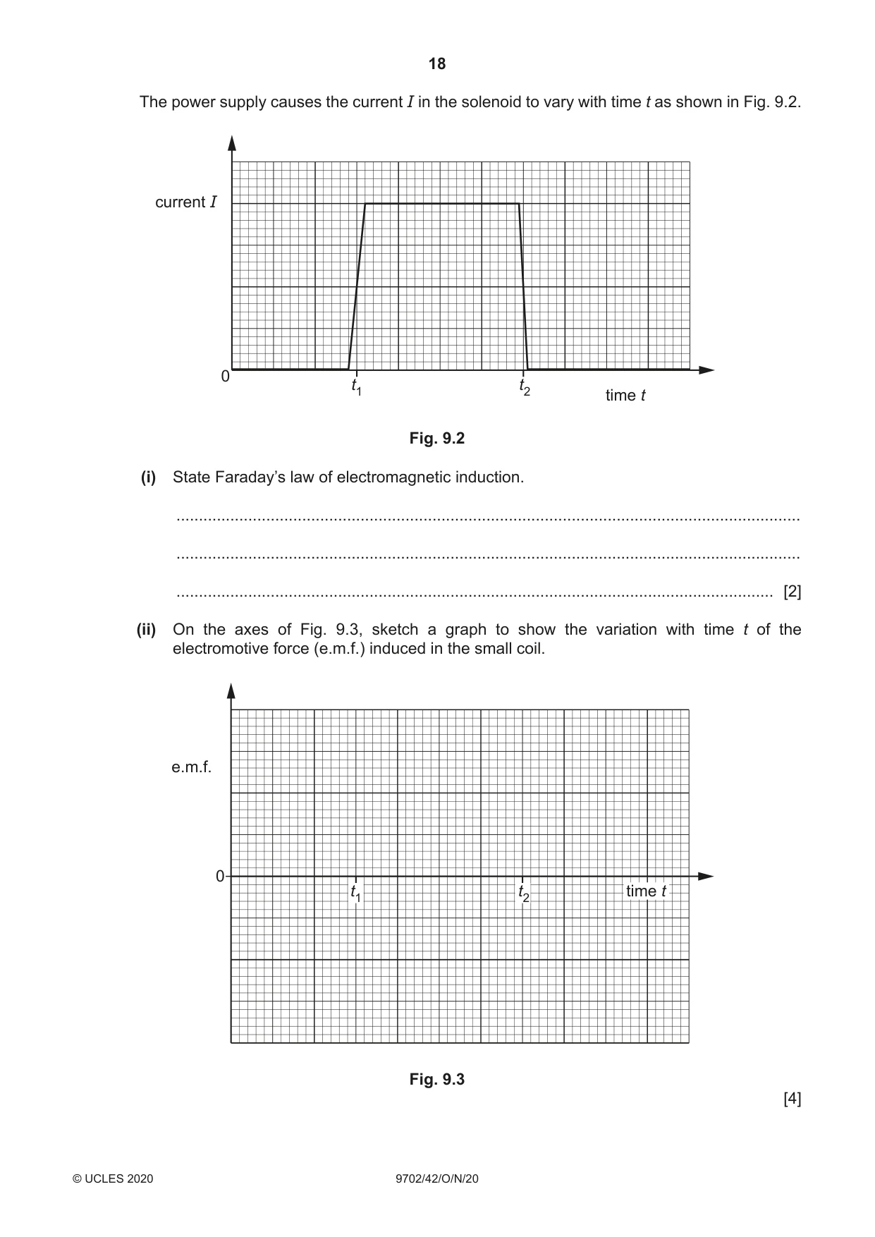
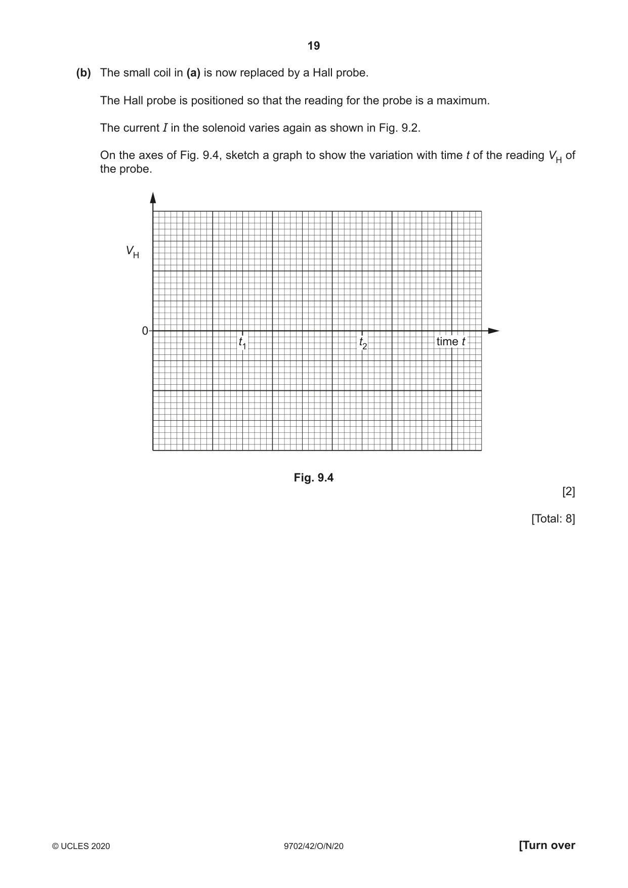
9 (a) A small coil is placed close to one end of a solenoid connected to a power supply. The plane of the small coil is normal to the axis of the solenoid, as illustrated in Fig. 9.1. solenoid small coil power supply Fig. 9.1 The power supply causes the current I in the solenoid to vary with time t as shown in Fig. 9.2. current I 0 t1 t2 time t Fig. 9.2 (i) State Faraday’s law of electromagnetic induction. ........................................................................................................................................... ........................................................................................................................................... ..................................................................................................................................... [2] (ii) On the axes of Fig. 9.3, sketch a graph to show the variation with time t of the electromotive force (e.m.f.) induced in the small coil. e.m.f. 0 t1 t2 time t Fig. 9.3 [4] (b) The small coil in (a) is now replaced by a Hall probe. The Hall probe is positioned so that the reading for the probe is a maximum. The current I in the solenoid varies again as shown in Fig. 9.2. On the axes of Fig. 9.4, sketch a graph to show the variation with time t of the reading VH of the probe. VH 0 t1 t2 time t Fig. 9.4 [2] [Total: 8]
Mark scheme: 9(a)(i) (induced) e.m.f. (directly) proportional to rate M1 of change of magnetic flux (linkage) A1 9(a)(ii) e.m.f. = 0 apart from thin pulses at t1 and t2 B1 rectangular pulses centred on t1 and t2, of widths 2 small squares and 1 small square respectively B1 e.m.fs. at t1 and t2 have opposite polarities B1 magnitude of e.m.f. at t2 double the magnitude of e.m.f. at t1 B1 9(b) VH shown as zero before (t1 – 2 squares) and after (t2 + 2 squares) and rises to a constant non-zero value between t1 and t2 M1 change at t1 shown as 2 small squares wide and change at t2 shown as 1 small square wide A1
Q10 · A long straight vertical wire A carries a current in an upward direction
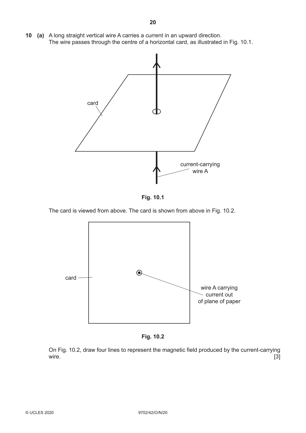
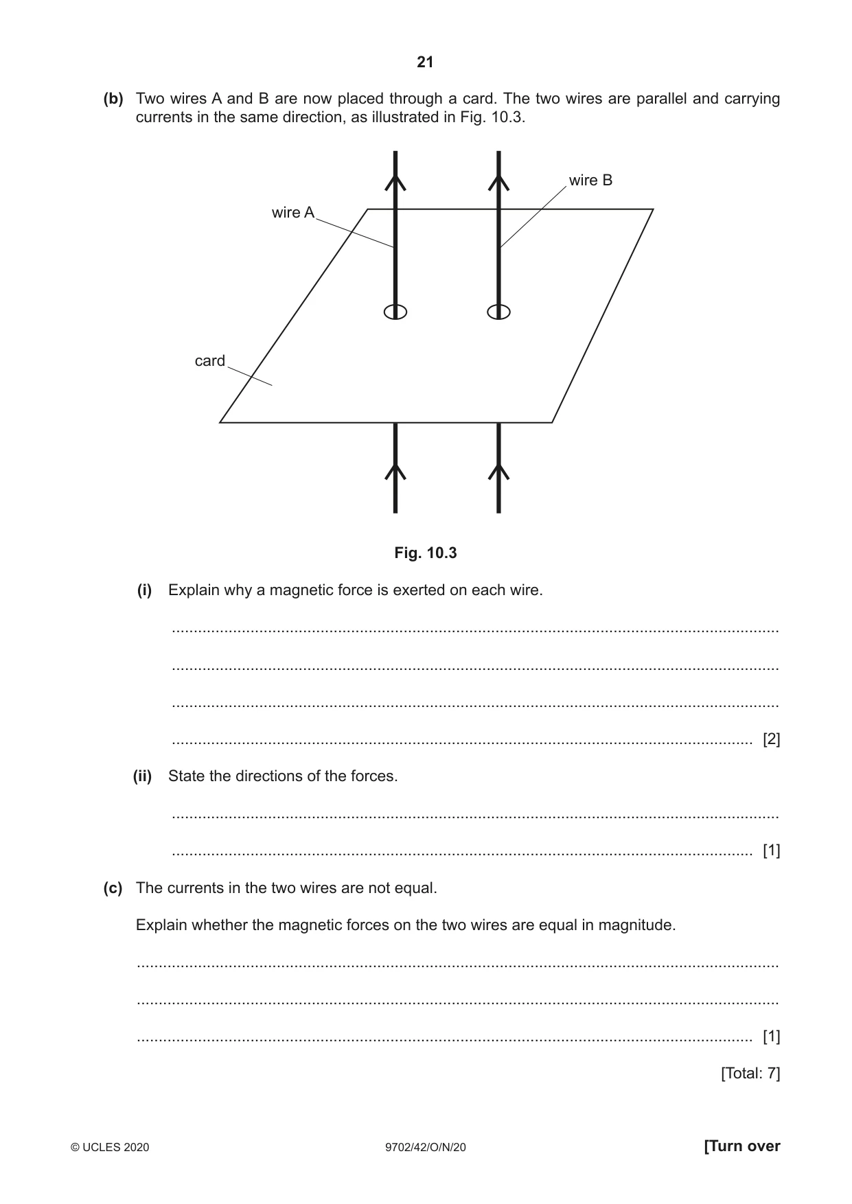
10 (a) A long straight vertical wire A carries a current in an upward direction. The wire passes through the centre of a horizontal card, as illustrated in Fig. 10.1. card current-carrying wire A Fig. 10.1 The card is viewed from above. The card is shown from above in Fig. 10.2. card wire A carrying current out of plane of paper Fig. 10.2 On Fig. 10.2, draw four lines to represent the magnetic field produced by the current-carrying wire. [3] (b) Two wires A and B are now placed through a card. The two wires are parallel and carrying currents in the same direction, as illustrated in Fig. 10.3. wire B wire A card Fig. 10.3 (i) Explain why a magnetic force is exerted on each wire. ........................................................................................................................................... ........................................................................................................................................... ........................................................................................................................................... ..................................................................................................................................... [2] (ii) State the directions of the forces. ........................................................................................................................................... ..................................................................................................................................... [1] (c) The currents in the two wires are not equal. Explain whether the magnetic forces on the two wires are equal in magnitude. ................................................................................................................................................... ................................................................................................................................................... ............................................................................................................................................. [1] [Total: 7]
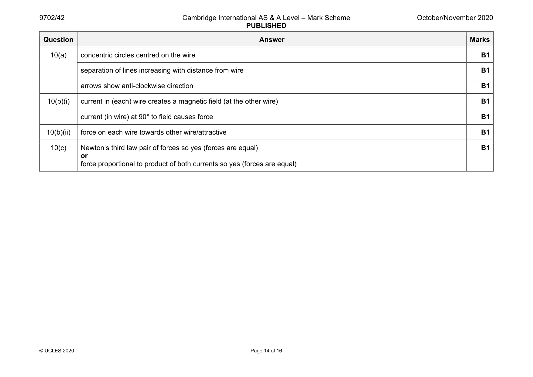
Mark scheme: 10(a) concentric circles centred on the wire B1 separation of lines increasing with distance from wire B1 arrows show anti-clockwise direction B1 10(b)(i) current in (each) wire creates a magnetic field (at the other wire) B1 current (in wire) at 90° to field causes force B1 10(b)(ii) force on each wire towards other wire/attractive B1 10(c) Newton’s third law pair of forces so yes (forces are equal) or force proportional to product of both currents so yes (forces are equal) B1
Q11 · Electromagnetic radiation is incident on a metal surface
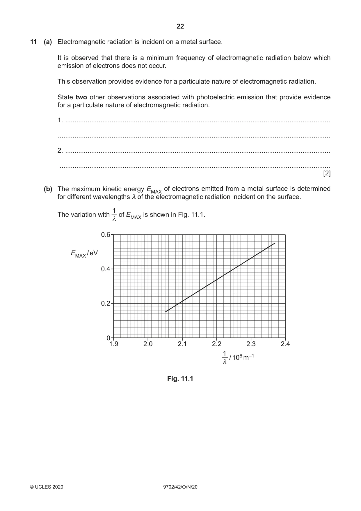
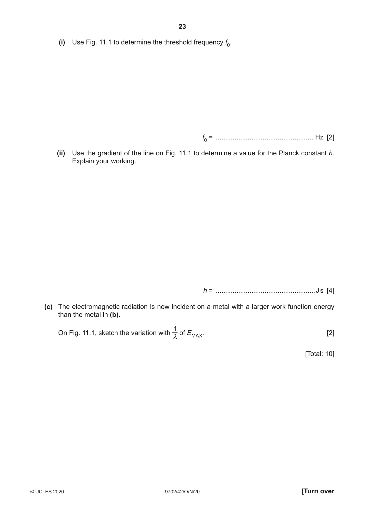
11 (a) Electromagnetic radiation is incident on a metal surface. It is observed that there is a minimum frequency of electromagnetic radiation below which emission of electrons does not occur. This observation provides evidence for a particulate nature of electromagnetic radiation. State two other observations associated with photoelectric emission that provide evidence for a particulate nature of electromagnetic radiation. 1. ............................................................................................................................................... ................................................................................................................................................... 2. ............................................................................................................................................... .................................................................................................................................................. [2] (b) The maximum kinetic energy EMAX of electrons emitted from a metal surface is determined for different wavelengths λ of the electromagnetic radiation incident on the surface. 1 The variation with of EMAX is shown in Fig. 11.1. λ 0.6 EMAX / eV 0.4 0.2 0 1.9 2.0 2.1 2.2 2.3 2.4 1 / 106 m–1 λ Fig. 11.1 (i) Use Fig. 11.1 to determine the threshold frequency f0. f0 = .................................................... Hz [2] (ii) Use the gradient of the line on Fig. 11.1 to determine a value for the Planck constant h. Explain your working. h = ..................................................... J s [4] (c) The electromagnetic radiation is now incident on a metal with a larger work function energy than the metal in (b). 1 On Fig. 11.1, sketch the variation with of EMAX. [2] λ [Total: 10]
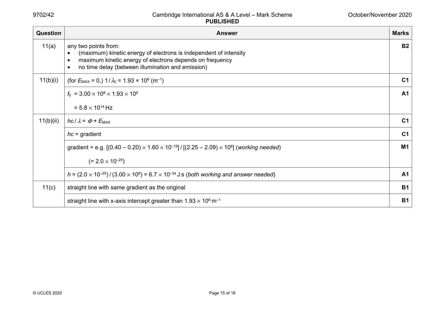
Mark scheme: 11(a) any two points from: • (maximum) kinetic energy of electrons is independent of intensity • maximum kinetic energy of electrons depends on frequency • no time delay (between illumination and emission) B2 11(b)(i) (for EMAX = 0,) 1 / λ0 = 1.93 × 10⁶ (m–1) C1 f0 = 3.00 × 108 × 1.93 × 106 = 5.8 × 10¹⁴ Hz A1 11(b)(ii) hc / λ = Φ + EMAX C1 hc = gradient C1 gradient = e.g. [(0.40 – 0.20) × 1.60 × 10–19] / [(2.25 – 2.09) × 106] (working needed) (= 2.0 × 10⁻²⁵) M1 h = (2.0 × 10⁻²⁵) / (3.00 × 10⁸) = 6.7 × 10⁻³⁴ J s (both working and answer needed) A1 11(c) straight line with same gradient as the original B1 straight line with x-axis intercept greater than 1.93 × 10⁶ m–1 B1
Q12 · Define nuclear binding energy
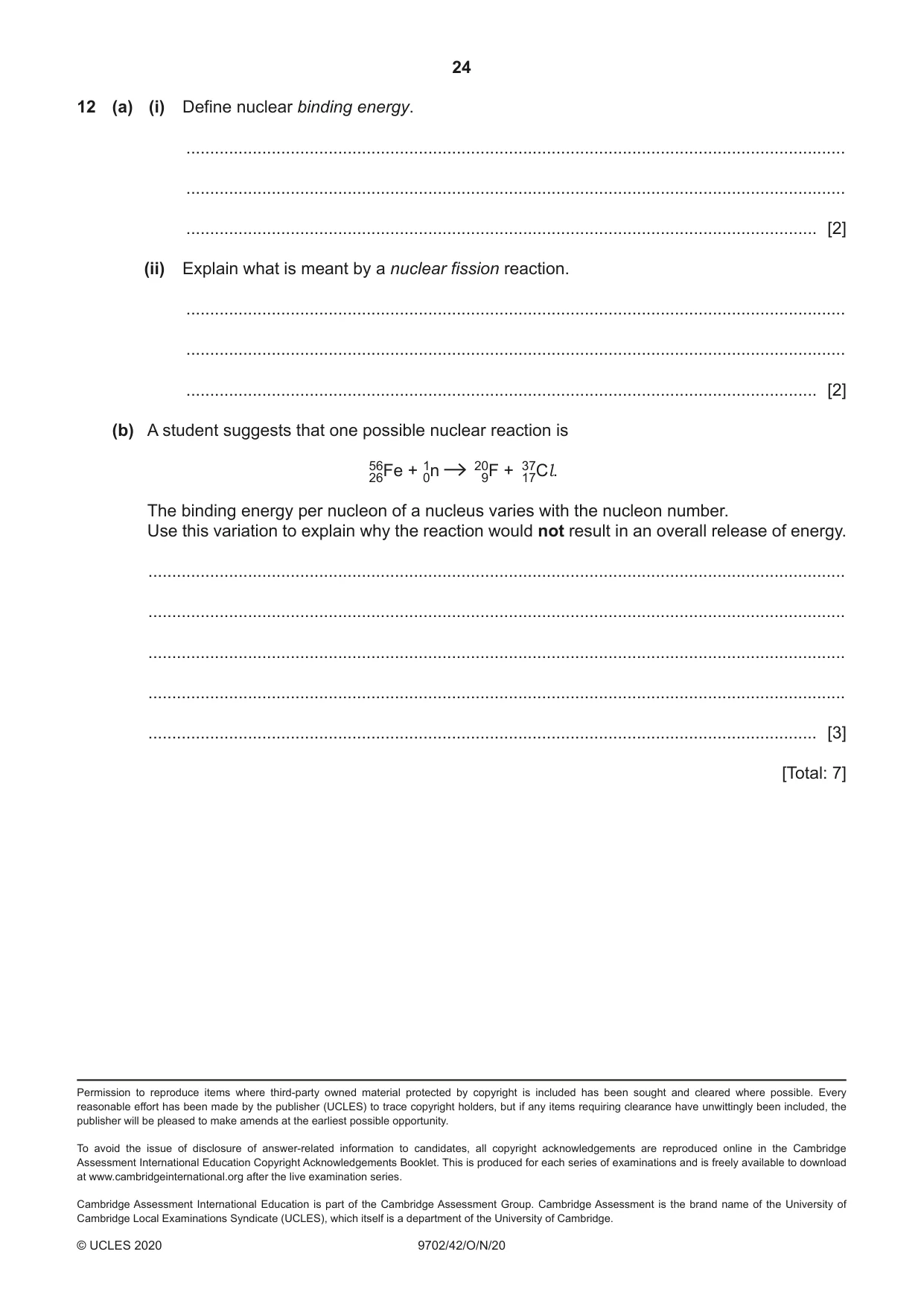
12 (a) (i) Define nuclear binding energy. ........................................................................................................................................... ........................................................................................................................................... ..................................................................................................................................... [2] (ii) Explain what is meant by a nuclear fission reaction. ........................................................................................................................................... ........................................................................................................................................... ..................................................................................................................................... [2] (b) A student suggests that one possible nuclear reaction is 5626Fe + 10n 209F + 3717Cl. The binding energy per nucleon of a nucleus varies with the nucleon number. Use this variation to explain why the reaction would not result in an overall release of energy. ................................................................................................................................................... ................................................................................................................................................... ................................................................................................................................................... ................................................................................................................................................... ............................................................................................................................................. [3] [Total: 7]
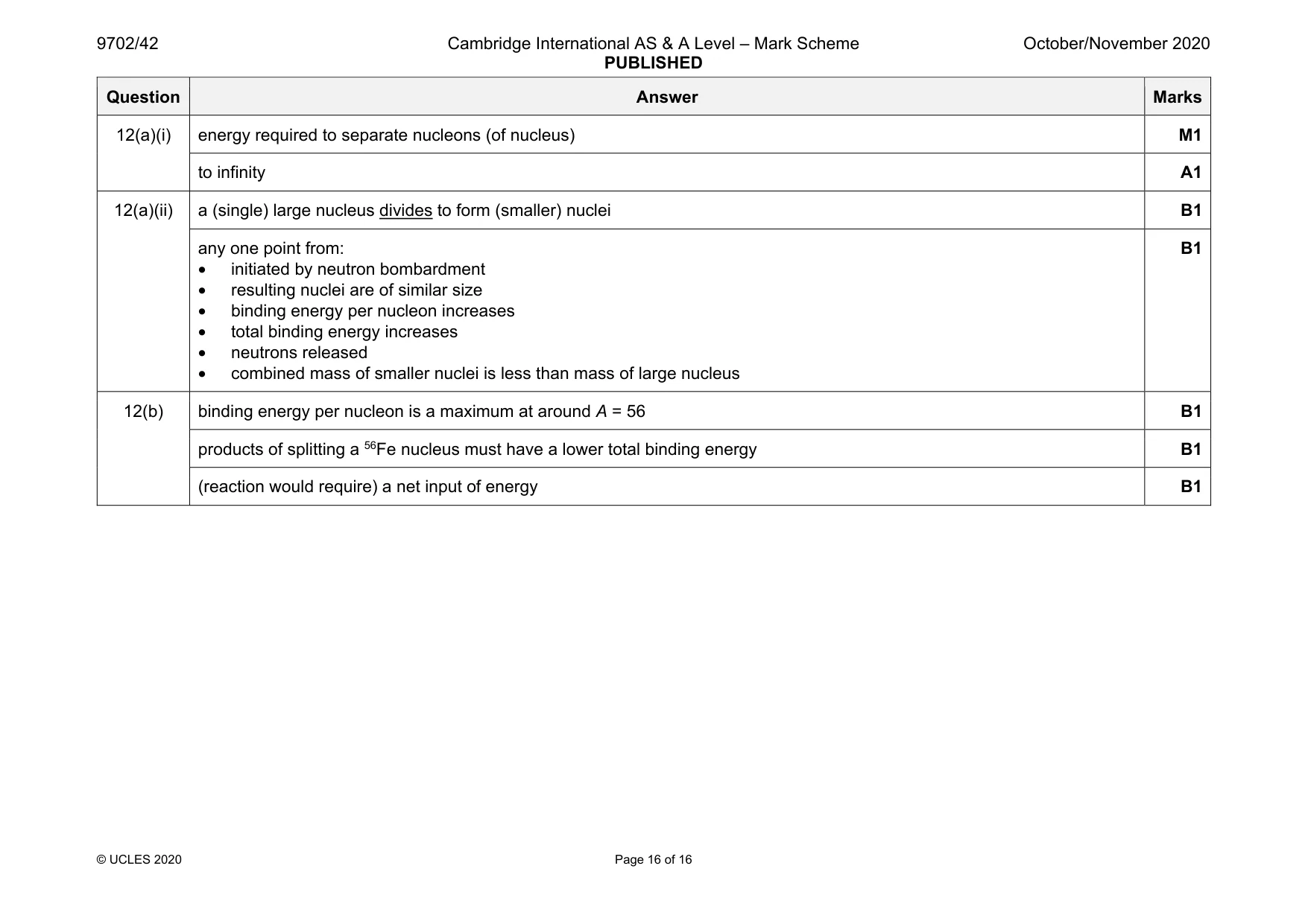
Mark scheme: 12(a)(i) energy required to separate nucleons (of nucleus) M1 to infinity A1 12(a)(ii) a (single) large nucleus divides to form (smaller) nuclei B1 any one point from: • initiated by neutron bombardment • resulting nuclei are of similar size • binding energy per nucleon increases • total binding energy increases • neutrons released • combined mass of smaller nuclei is less than mass of large nucleus B1 12(b) binding energy per nucleon is a maximum at around A = 56 B1 products of splitting a 56Fe nucleus must have a lower total binding energy B1 (reaction would require) a net input of energy B1
What was in this paper
The subtopics covered by these 12 questions, and how many questions each got. Open one in a new tab to see every Cambridge question on it.
1Electric fields and field lines1Electromagnetic induction1Equation of state1Linear momentum and its conservation1Magnetic fields due to currents1Mass defect and nuclear binding energy1Photoelectric effect1Practical circuits1Production and use of X-rays1Rectification and smoothing1Simple harmonic oscillations1What you needed in this session
Cambridge’s own grade thresholds for 2020 Oct/Nov, Paper 4 · Variant 2. A higher threshold means an easier paper — the bar moves with how the cohort did.