Cambridge A Level Physics 9702 — 2021 Feb/March Paper 4 · Variant 2
9702/42/F/M/21 · 12 questions · 100 marks · ≈113 min
The question paper and its mark scheme, free to read here and free to download. This is Cambridge’s own paper, exactly as it was sat.
Question paper28 pages



Mark scheme19 pages
Answers below. Sit the paper first if you are practising.
Questions as text
Q1 · State Newton’s law of gravitation
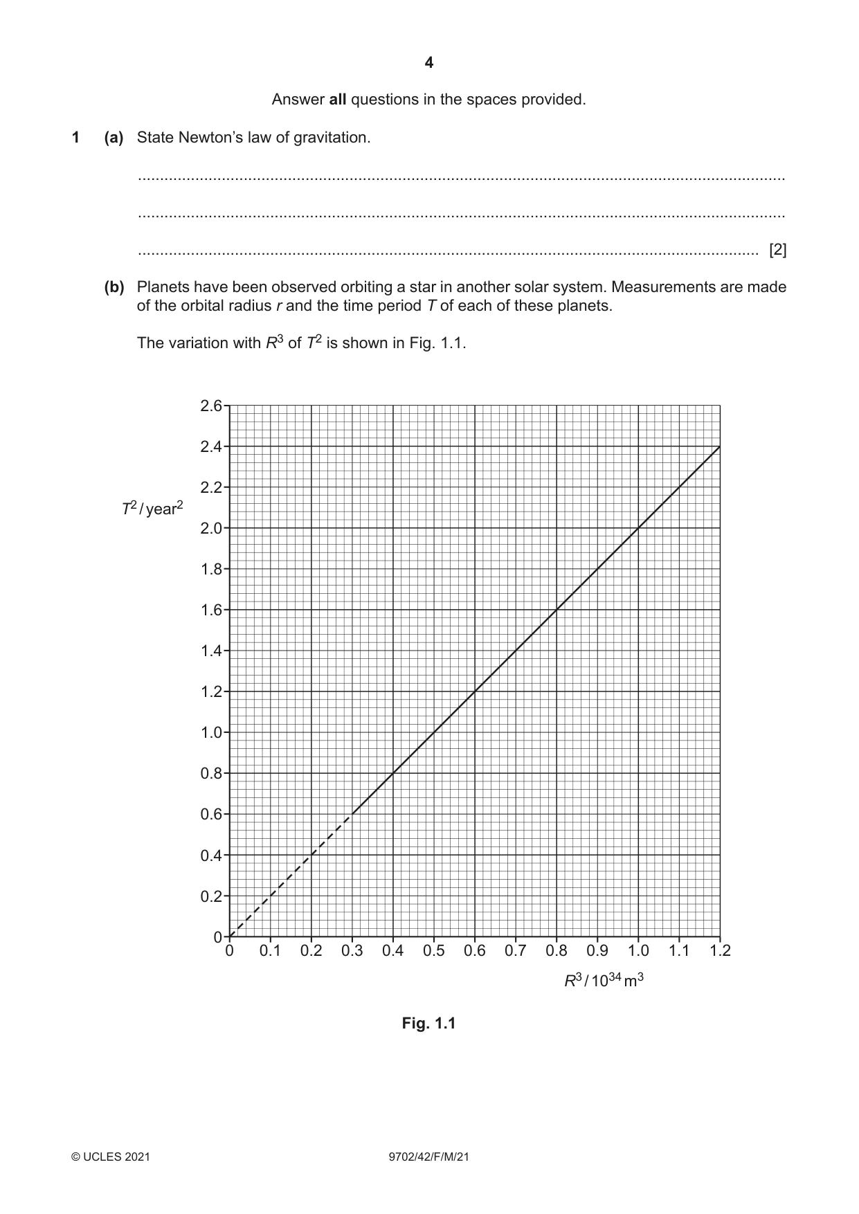
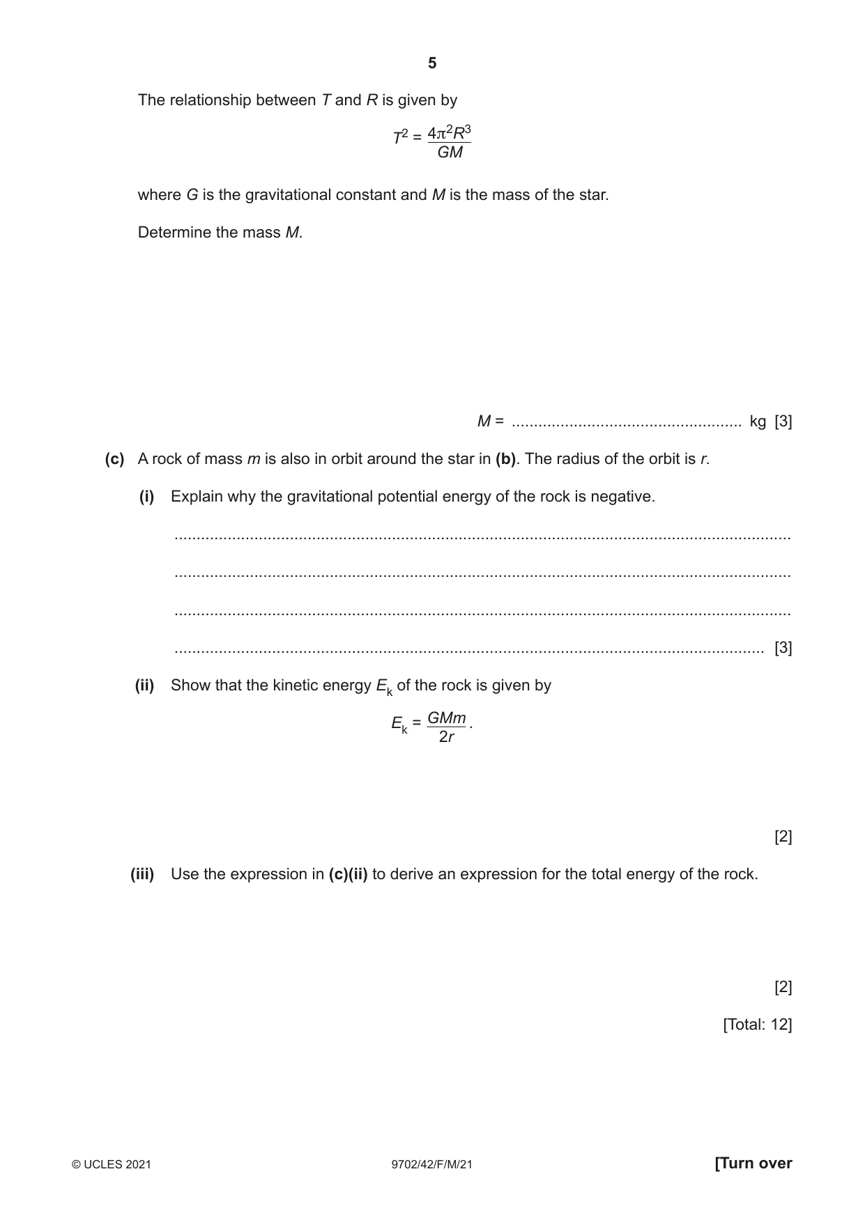
1 (a) State Newton’s law of gravitation. ................................................................................................................................................... ................................................................................................................................................... ............................................................................................................................................. [2] (b) Planets have been observed orbiting a star in another solar system. Measurements are made of the orbital radius r and the time period T of each of these planets. The variation with R3 of T2 is shown in Fig. 1.1. 2.6 2.4 2.2 T2 / year2 2.0 1.8 1.6 1.4 1.2 1.0 0.8 0.6 0.4 0.2 0 0 0.1 0.2 0.3 0.4 0.5 0.6 0.7 0.8 0.9 1.0 1.1 1.2 R3 / 1034 m3 Fig. 1.1 The relationship between T and R is given by T2 = 4π2R3 GM where G is the gravitational constant and M is the mass of the star. Determine the mass M. M = .................................................... kg [3] (c) A rock of mass m is also in orbit around the star in (b). The radius of the orbit is r. (i) Explain why the gravitational potential energy of the rock is negative. ........................................................................................................................................... ........................................................................................................................................... ........................................................................................................................................... ..................................................................................................................................... [3] (ii) Show that the kinetic energy Ek of the rock is given by Ek = GMm . 2r [2] (iii) Use the expression in (c)(ii) to derive an expression for the total energy of the rock. [2] [Total: 12]
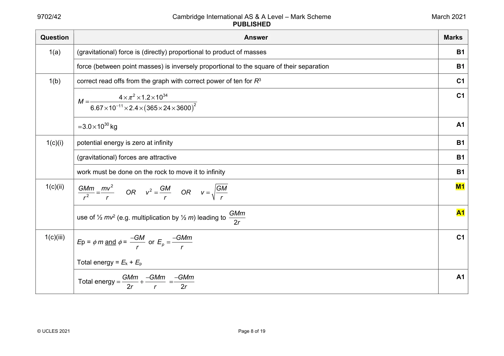
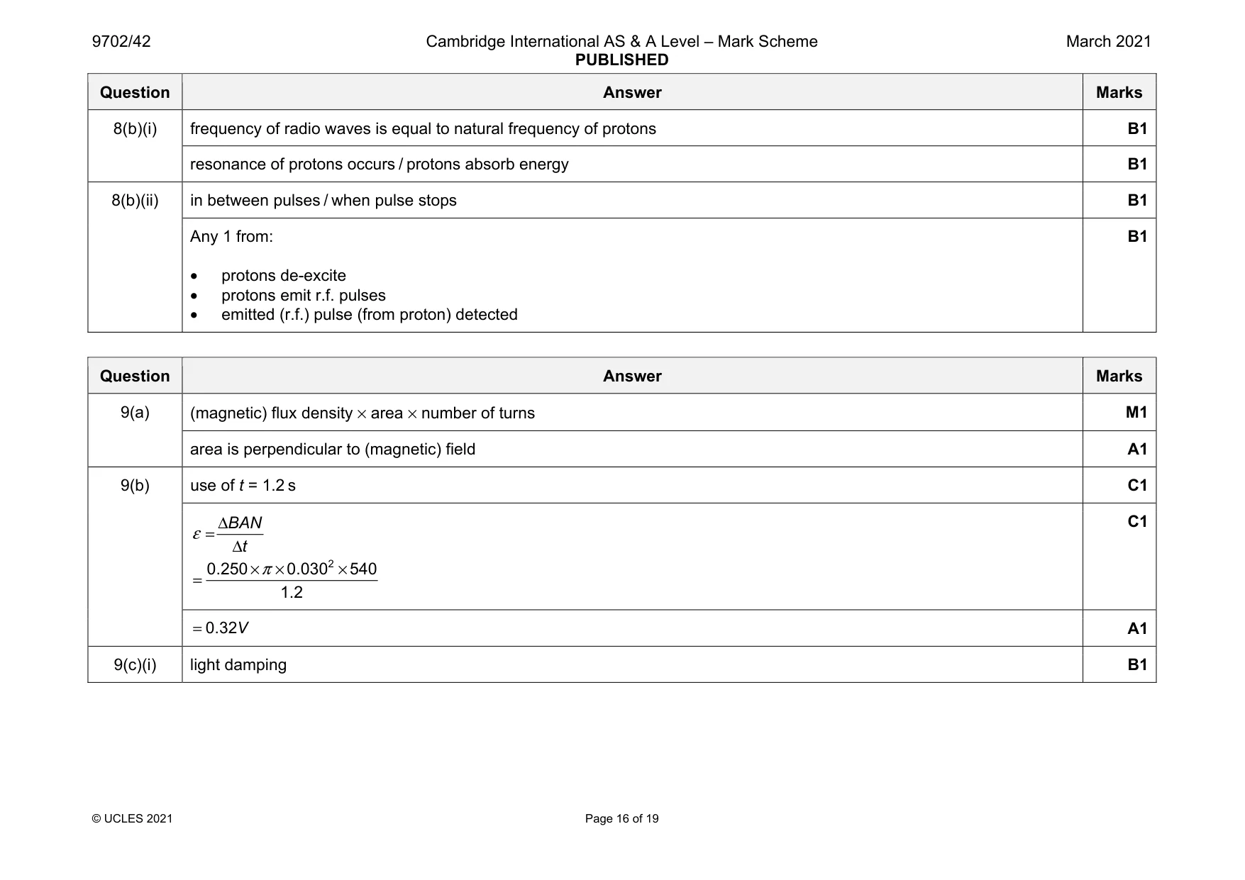
Mark scheme: 1(a) (gravitational) force is (directly) proportional to product of masses B1 force (between point masses) is inversely proportional to the square of their separation B1 1(b) correct read offs from the graph with correct power of ten for R3 C1 ( ) 2 34 2 11 4 1.2 10 6.67 10 2.4 365 24 3600 M π − × × × = × × × × × C1 30 3.0 10 kg = × A1 1(c)(i) potential energy is zero at infinity B1 (gravitational) forces are attractive B1 work must be done on the rock to move it to infinity B1 1(c)(ii) 2 2 2 GMm mv GM GM OR v OR v r r r r = = = M1 use of ½ mv2 (e.g. multiplication by ½ m) leading to 2 GMm r A1 1(c)(iii) Ep = φ m and φ = GM r − or p GMm E r − = Total energy = Ek + Ep C1 Total energy 2 GMm GMm r r − = + 2 GMm r − = A1
Q2 · A fixed mass of an ideal gas is at a temperature of 21 °C
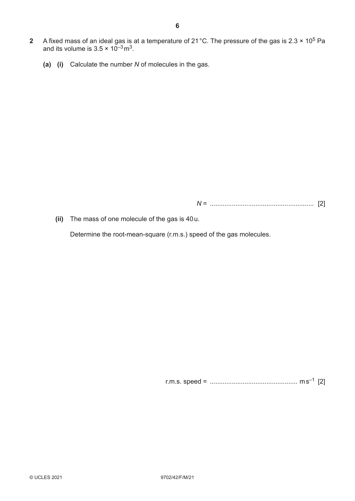
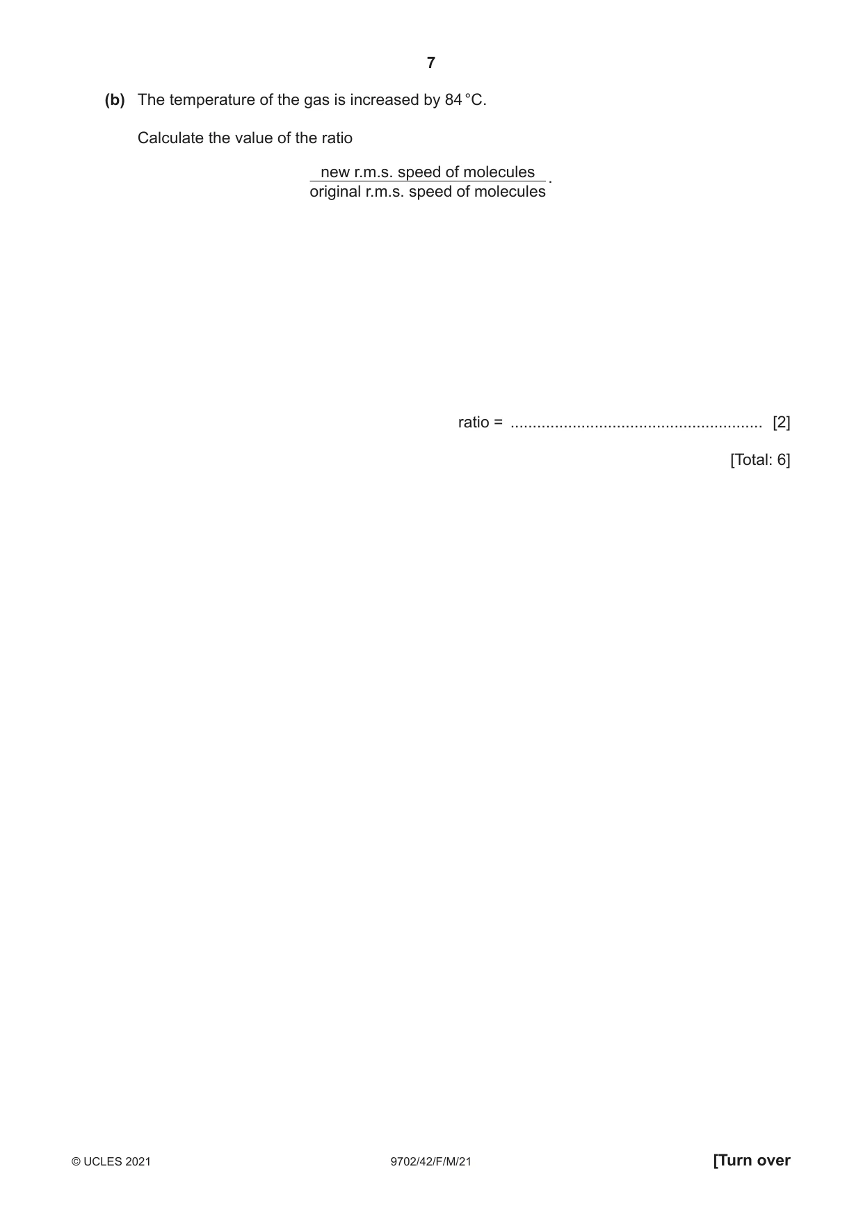
2 A fixed mass of an ideal gas is at a temperature of 21 °C. The pressure of the gas is 2.3 × 10⁵ Pa and its volume is 3.5 × 10⁻³ m3. (a) (i) Calculate the number N of molecules in the gas. N = ......................................................... [2] (ii) The mass of one molecule of the gas is 40 u. Determine the root-mean-square (r.m.s.) speed of the gas molecules. r.m.s. speed = ................................................ m s–1 [2] (b) The temperature of the gas is increased by 84 °C. Calculate the value of the ratio new r.m.s. speed of molecules original r.m.s. speed of molecules . ratio = ......................................................... [2] [Total: 6]
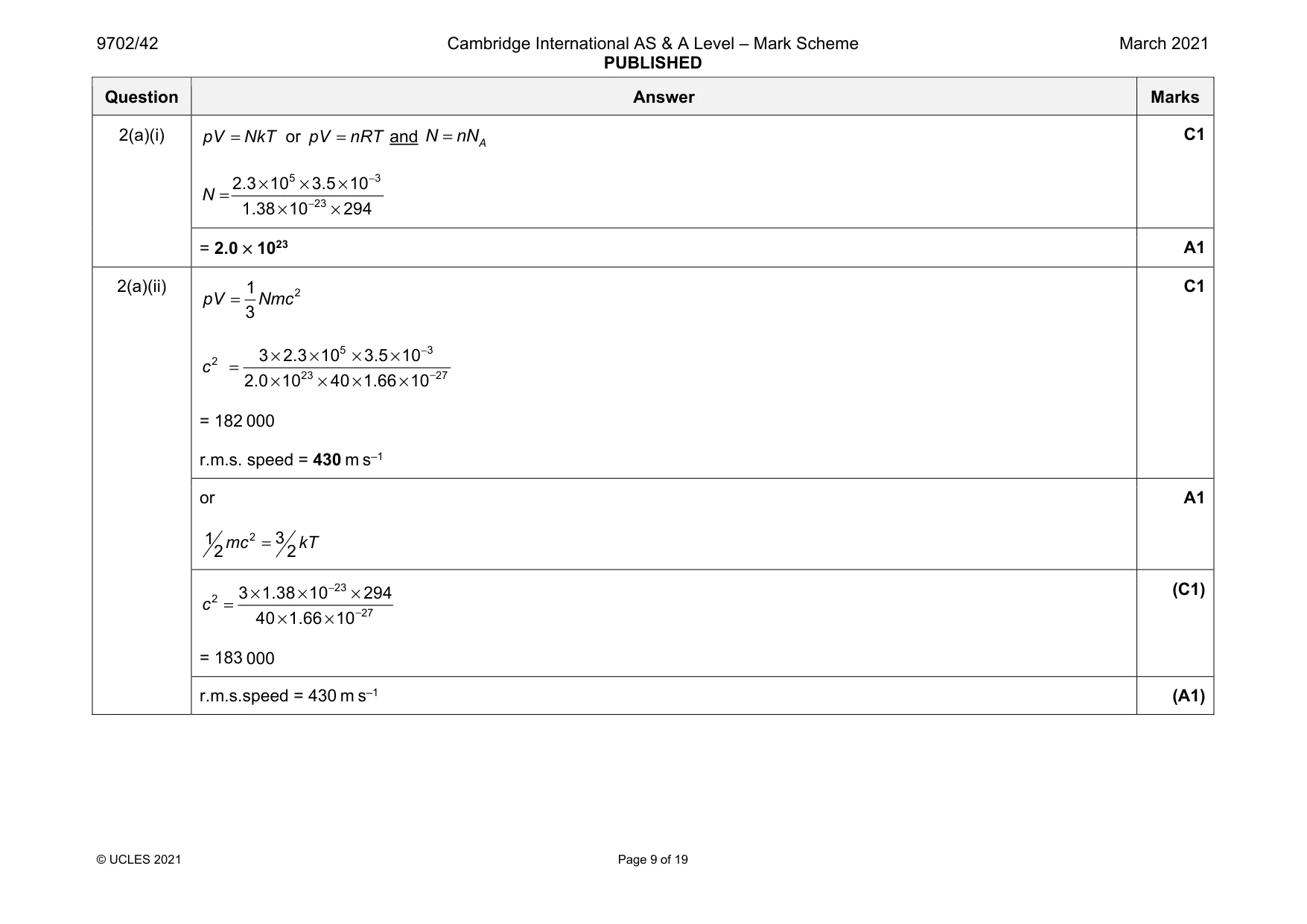
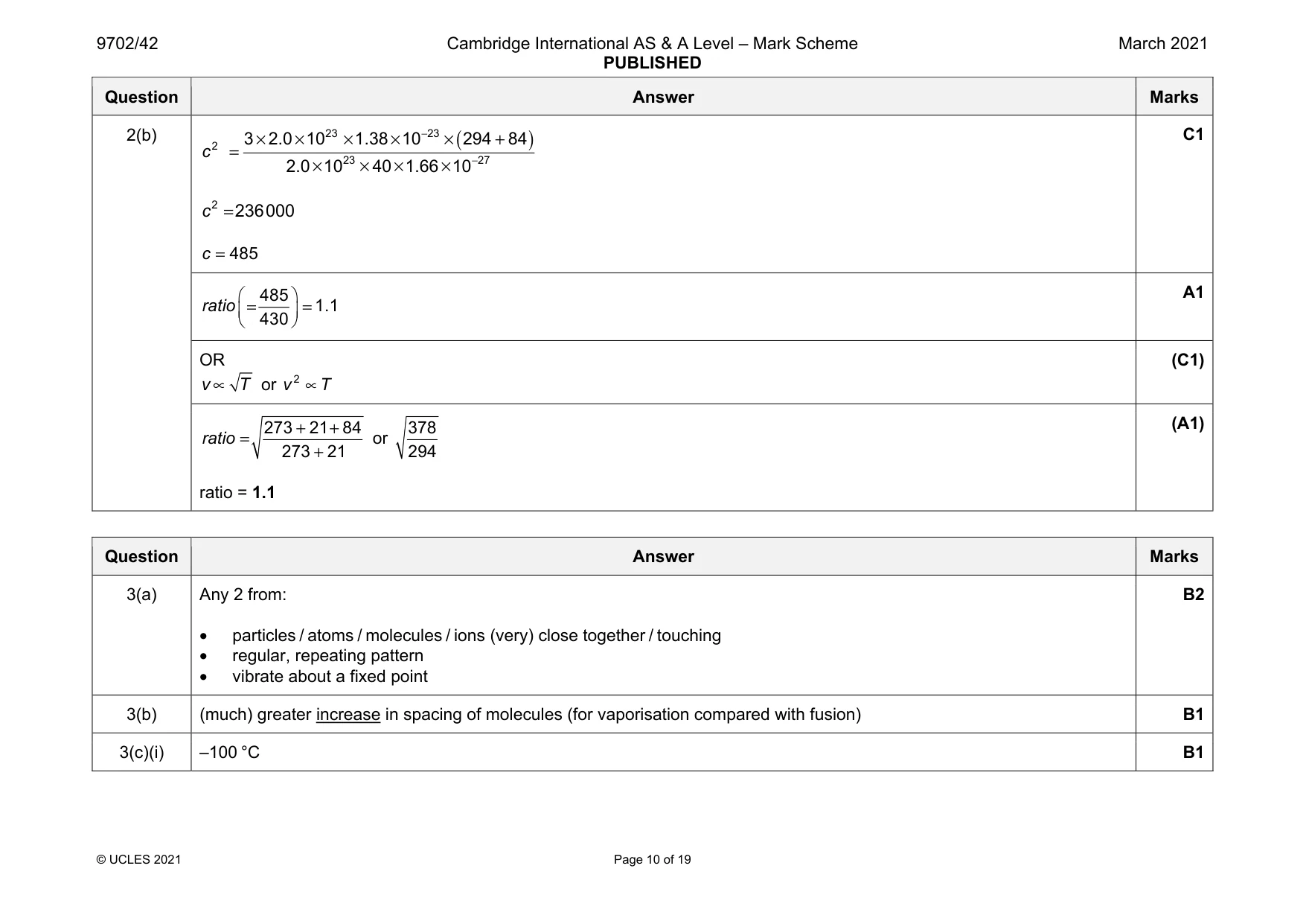
Mark scheme: 2(a)(i) pV NkT = or pV nRT = and A N nN = 5 3 23 2.3 10 3.5 10 1.38 10 294 N − − × × × = × × = 2.0 × 10²³ A1 2(a)(ii) 2 1 3 pV Nmc = 5 3 2 23 27 3 2.3 10 3.5 10 2.0 10 40 1.66 10 c − − × × × × = × × × × = 182 000 r.m.s. speed = 430 m s–1 C1 or 2 3 12 2 mc kT = A1 23 2 27 3 1.38 10 294 40 1.66 10 c − − × × × = × × = 183 000 (C1) r.m.s.speed = 430 m s–1 (A1) Question Answer Marks 2(b) ( ) 23 23 2 23 27 3 2.0 10 1.38 10 294 84 2.0 10 40 1.66 10 c − − × × × × × + = × × × × 2 236000 c = 485 c = C1 485 1.1 430 ratio = = A1 OR v T ∝ or 2 v T ∝ (C1) 273 21 84 273 21 ratio + + = + or 378 294 ratio = 1.1 (A1)
Q3 · Using a simple kinetic model of matter, describe the structure of a solid
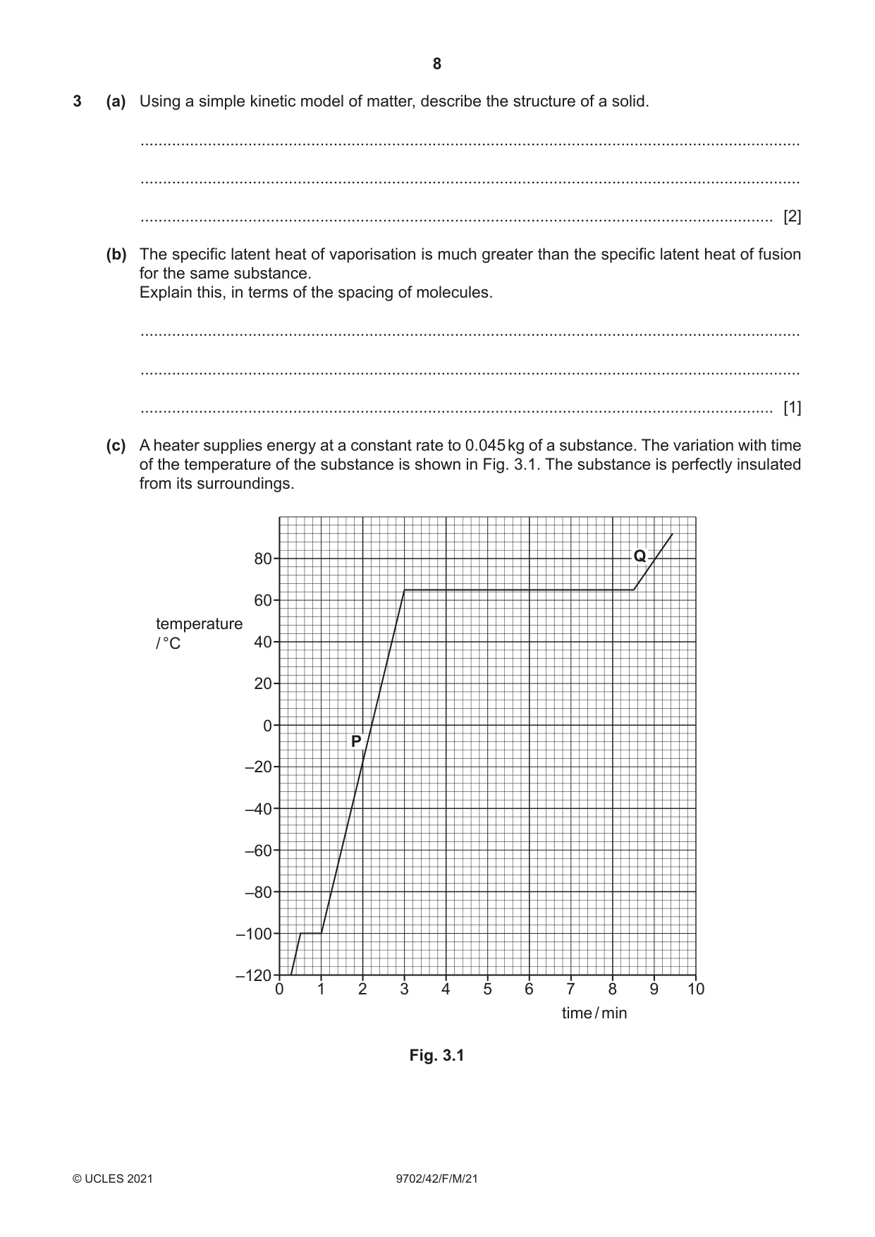
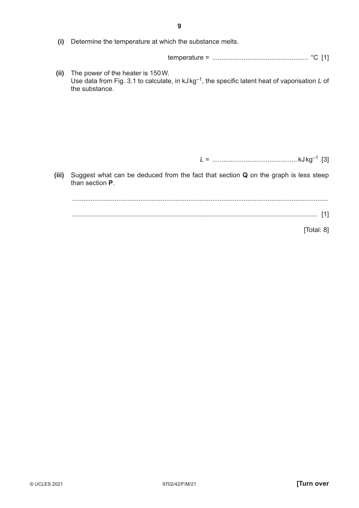
3 (a) Using a simple kinetic model of matter, describe the structure of a solid. ................................................................................................................................................... ................................................................................................................................................... ............................................................................................................................................. [2] (b) The specific latent heat of vaporisation is much greater than the specific latent heat of fusion for the same substance. Explain this, in terms of the spacing of molecules. ................................................................................................................................................... ................................................................................................................................................... ............................................................................................................................................. [1] (c) A heater supplies energy at a constant rate to 0.045 kg of a substance. The variation with time of the temperature of the substance is shown in Fig. 3.1. The substance is perfectly insulated from its surroundings. 80 Q 60 temperature / °C 40 20 0 P –20 –40 –60 –80 –100 –120 0 1 2 3 4 5 6 7 8 9 10 time / min Fig. 3.1 (i) Determine the temperature at which the substance melts. temperature = .................................................... °C [1] (ii) The power of the heater is 150 W. Use data from Fig. 3.1 to calculate, in kJ kg–1, the specific latent heat of vaporisation L of the substance. L = .............................................. kJ kg–1 [3] (iii) Suggest what can be deduced from the fact that section Q on the graph is less steep than section P. ........................................................................................................................................... ..................................................................................................................................... [1] [Total: 8]
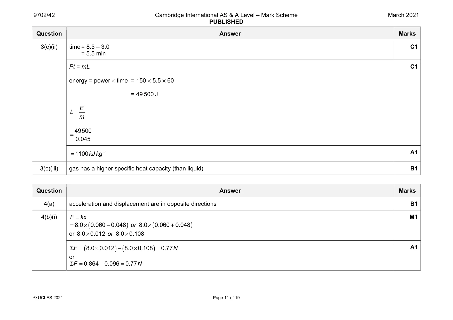
Mark scheme: 3(a) Any 2 from: • particles / atoms / molecules / ions (very) close together / touching • regular, repeating pattern • vibrate about a fixed point B2 3(b) (much) greater increase in spacing of molecules (for vaporisation compared with fusion) B1 3(c)(i) –100 °C B1 Question Answer Marks 3(c)(ii) time = 8.5 – 3.0 = 5.5 min C1 Pt = mL energy = power × time = 150 × 5.5 × 60 = 49 500 J E L m = 49 500 0.045 = C1 1 1100 kJ kg − = A1 3(c)(iii) gas has a higher specific heat capacity (than liquid) B1
More questions on Specific heat capacity and specific latent heat
Q4 · The defining equation of simple harmonic motion is a = – ω 2x
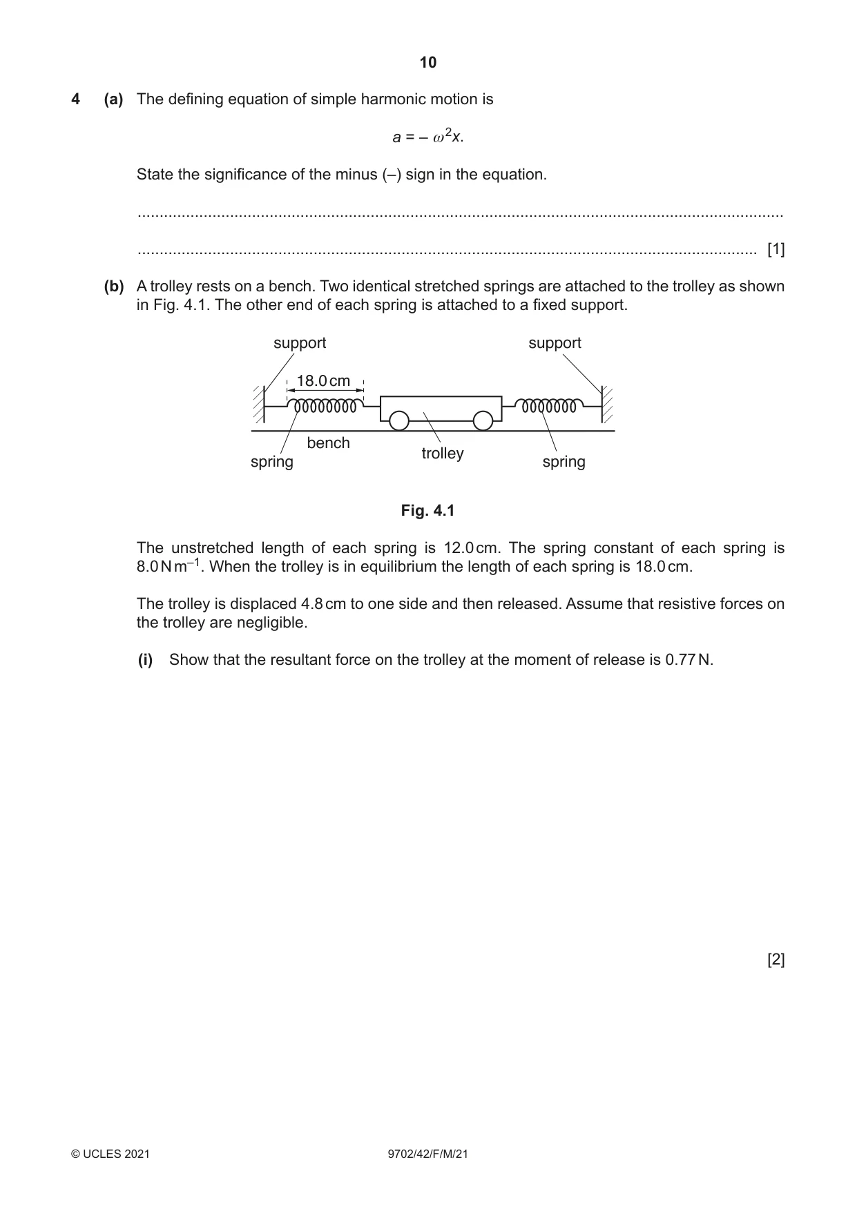
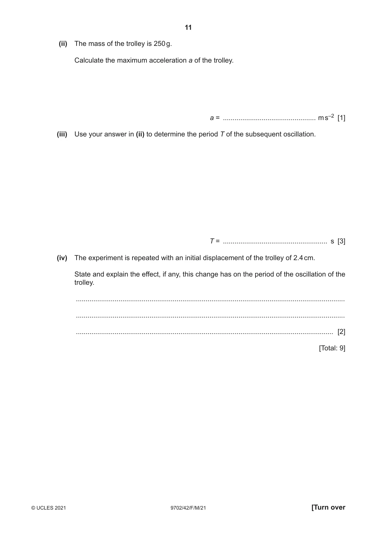
4 (a) The defining equation of simple harmonic motion is a = – ω 2x. State the significance of the minus (–) sign in the equation. ................................................................................................................................................... ............................................................................................................................................. [1] (b) A trolley rests on a bench. Two identical stretched springs are attached to the trolley as shown in Fig. 4.1. The other end of each spring is attached to a fixed support. support support 18.0 cm bench trolley spring spring Fig. 4.1 The unstretched length of each spring is 12.0 cm. The spring constant of each spring is 8.0 N m–1. When the trolley is in equilibrium the length of each spring is 18.0 cm. The trolley is displaced 4.8 cm to one side and then released. Assume that resistive forces on the trolley are negligible. (i) Show that the resultant force on the trolley at the moment of release is 0.77 N. [2] (ii) The mass of the trolley is 250 g. Calculate the maximum acceleration a of the trolley. a = ................................................ m s–2 [1] (iii) Use your answer in (ii) to determine the period T of the subsequent oscillation. T = ...................................................... s [3] (iv) The experiment is repeated with an initial displacement of the trolley of 2.4 cm. State and explain the effect, if any, this change has on the period of the oscillation of the trolley. ........................................................................................................................................... ........................................................................................................................................... ..................................................................................................................................... [2] [Total: 9]
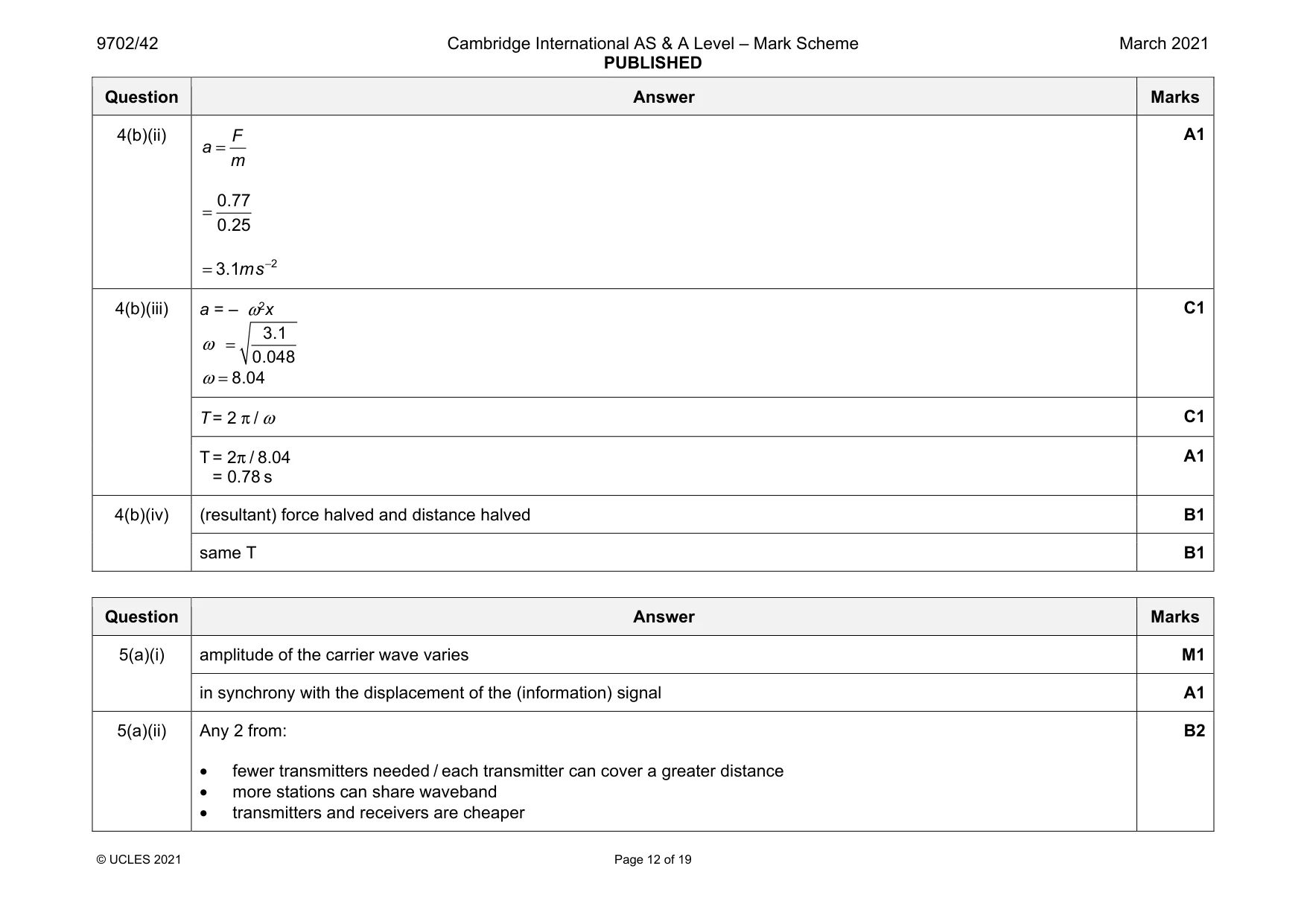
Mark scheme: 4(a) acceleration and displacement are in opposite directions B1 4(b)(i) F kx = ( ) ( ) 8.0 0.060 0.048 8.0 0.060 0.048 or = × − × + or 8.0 0.012 8.0 0.108 or × × M1 ( ) ( ) 8.0 0.012 8.0 0.108 0.77 F N Σ = × − × = or 0.864 0.096 0.77 F N Σ = − = A1 Question Answer Marks 4(b)(ii) F a m = 0.77 0.25 = 2 3.1 ms− = A1 4(b)(iii) a = – ω2x 3.1 0.048 ω = 8.04 ω = C1 T = 2 π / ω C1 T = 2π / 8.04 = 0.78 s A1 4(b)(iv) (resultant) force halved and distance halved B1 same T B1
Q5 · State what is meant by the amplitude modulation (AM) of a radio wave
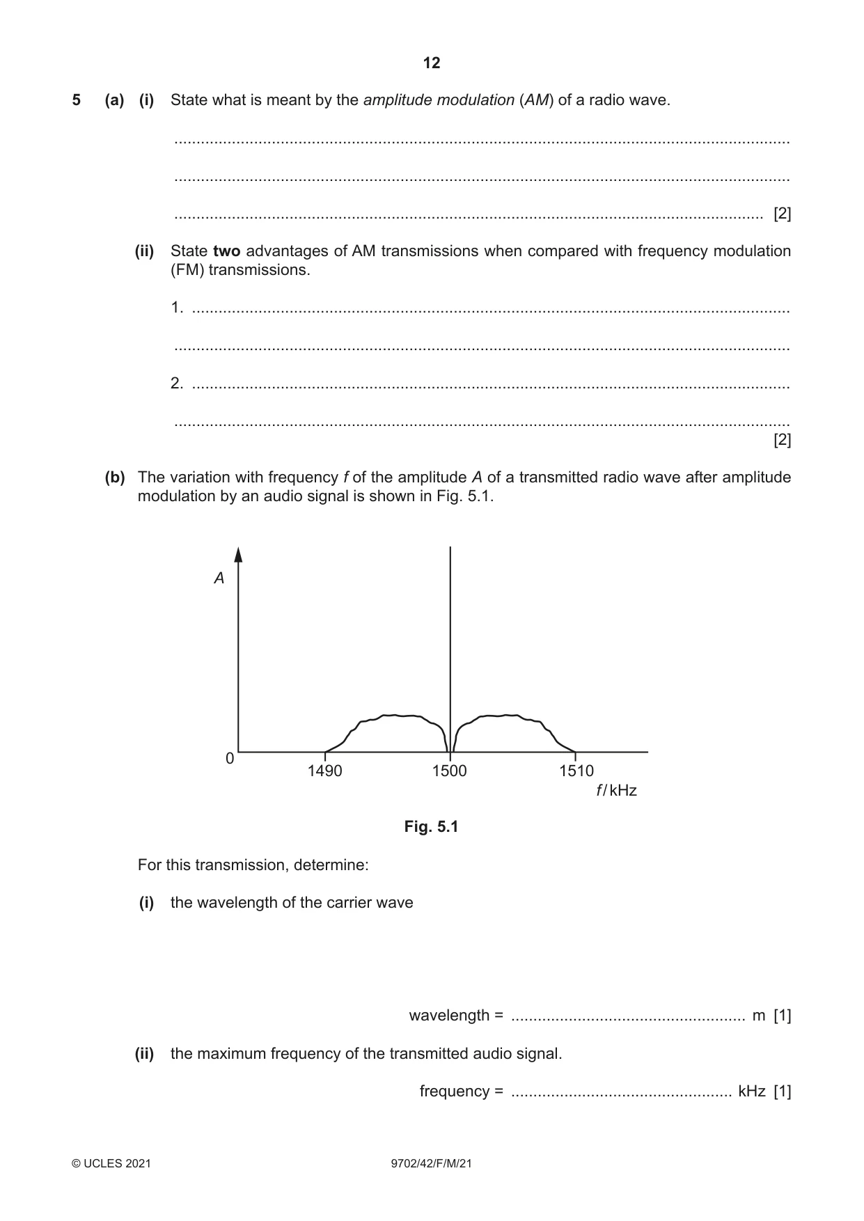
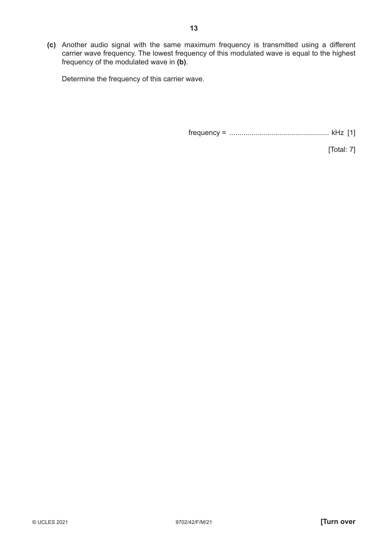
5 (a) (i) State what is meant by the amplitude modulation (AM) of a radio wave. ........................................................................................................................................... ........................................................................................................................................... ..................................................................................................................................... [2] (ii) State two advantages of AM transmissions when compared with frequency modulation (FM) transmissions. 1. ....................................................................................................................................... ........................................................................................................................................... 2. ....................................................................................................................................... ........................................................................................................................................... [2] (b) The variation with frequency f of the amplitude A of a transmitted radio wave after amplitude modulation by an audio signal is shown in Fig. 5.1. A 0 1490 1500 1510 f / kHz Fig. 5.1 For this transmission, determine: (i) the wavelength of the carrier wave wavelength = ..................................................... m [1] (ii) the maximum frequency of the transmitted audio signal. frequency = .................................................. kHz [1] (c) Another audio signal with the same maximum frequency is transmitted using a different carrier wave frequency. The lowest frequency of this modulated wave is equal to the highest frequency of the modulated wave in (b). Determine the frequency of this carrier wave. frequency = .................................................. kHz [1] [Total: 7]
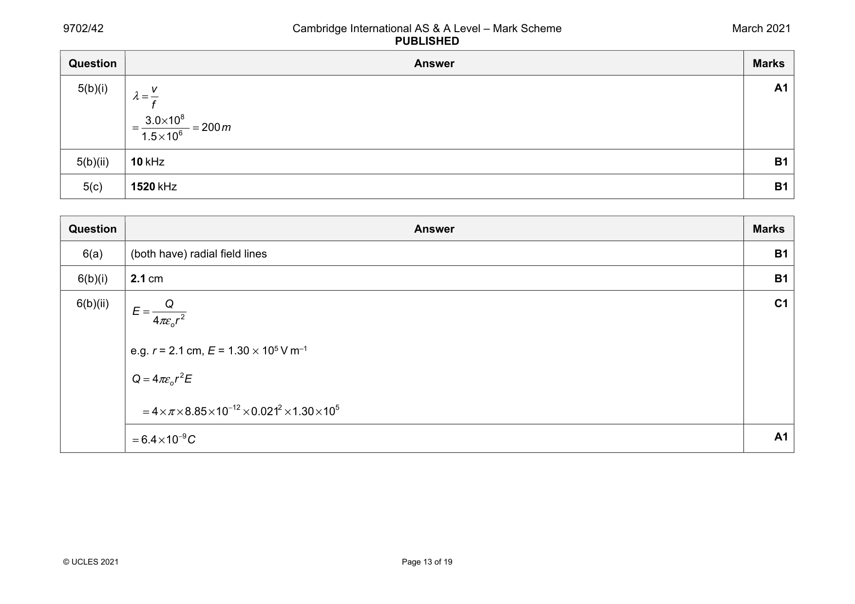
Mark scheme: 5(a)(i) amplitude of the carrier wave varies M1 in synchrony with the displacement of the (information) signal A1 5(a)(ii) Any 2 from: • fewer transmitters needed / each transmitter can cover a greater distance • more stations can share waveband • transmitters and receivers are cheaper B2 Question Answer Marks 5(b)(i) v f λ = 8 6 3.0 10 200 1.5 10 m × = = × A1 5(b)(ii) 10 kHz B1 5(c) 1520 kHz B1
Q6 · State a similarity between the gravitational field lines around a point mass and the…
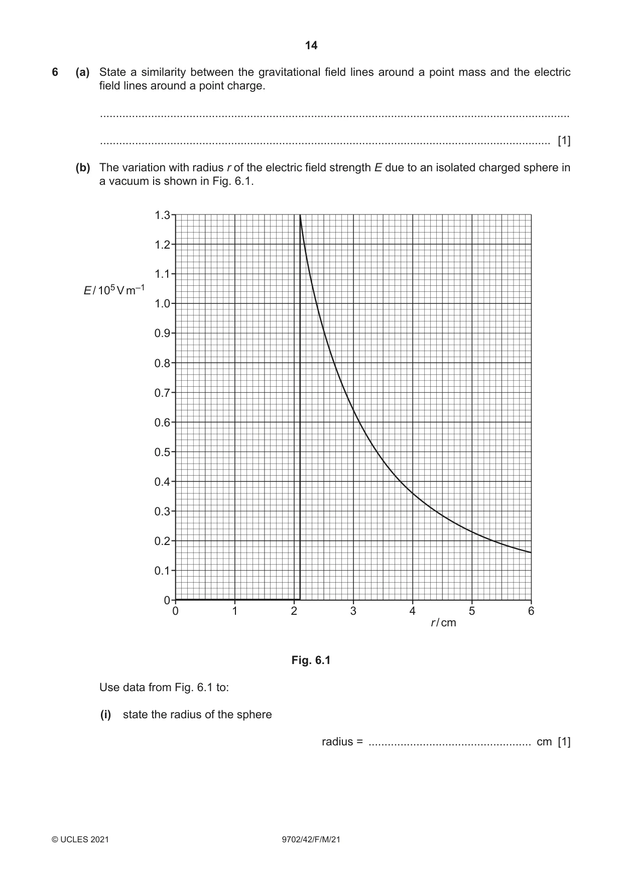
6 (a) State a similarity between the gravitational field lines around a point mass and the electric field lines around a point charge. ................................................................................................................................................... ............................................................................................................................................. [1] (b) The variation with radius r of the electric field strength E due to an isolated charged sphere in a vacuum is shown in Fig. 6.1. 1.3 1.2 1.1 E / 105 V m–1 1.0 0.9 0.8 0.7 0.6 0.5 0.4 0.3 0.2 0.1 0 0 1 2 3 4 5 6 r / cm Fig. 6.1 Use data from Fig. 6.1 to: (i) state the radius of the sphere radius = ................................................... cm [1] (ii) calculate the charge on the sphere. charge = ..................................................... C [2] (c) Using the formula for the electric potential due to an isolated point charge, determine the capacitance of the sphere in (b). capacitance = ...................................................... F [3] [Total: 7]
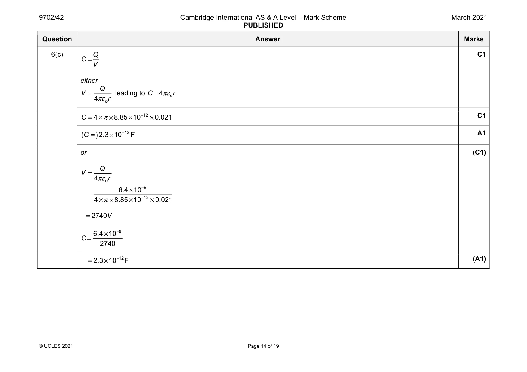
Mark scheme: 6(a) (both have) radial field lines B1 6(b)(i) 2.1 cm B1 6(b)(ii) 2 4 o Q E r πε = e.g. r = 2.1 cm, E = 1.30 × 10⁵ V m–1 2 4 o Q r E πε = 12 2 5 4 8.85 10 0.021 1.30 10 π − = × × × × × × C1 9 6.4 10 C − = × A1 Question Answer Marks 6(c) Q C V = either 4 o Q V r πε = leading to 4 o C r πε = C1 12 4 8.85 10 0.021 C π − = × × × × C1 ( ) 12 2.3 10 C − = × F A1 or 4 o Q V r πε = 9 12 6.4 10 4 8.85 10 0.021 π − − × = × × × × 2740 V = 9 6.4 10 2740 C − × = (C1) 12 2.3 10 F − = × (A1)
Q7 · The circuit diagram containing an operational amplifier (op-amp)
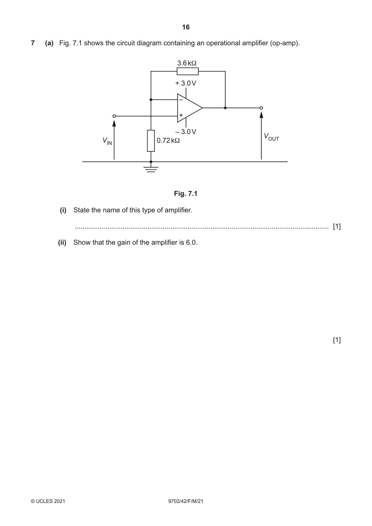
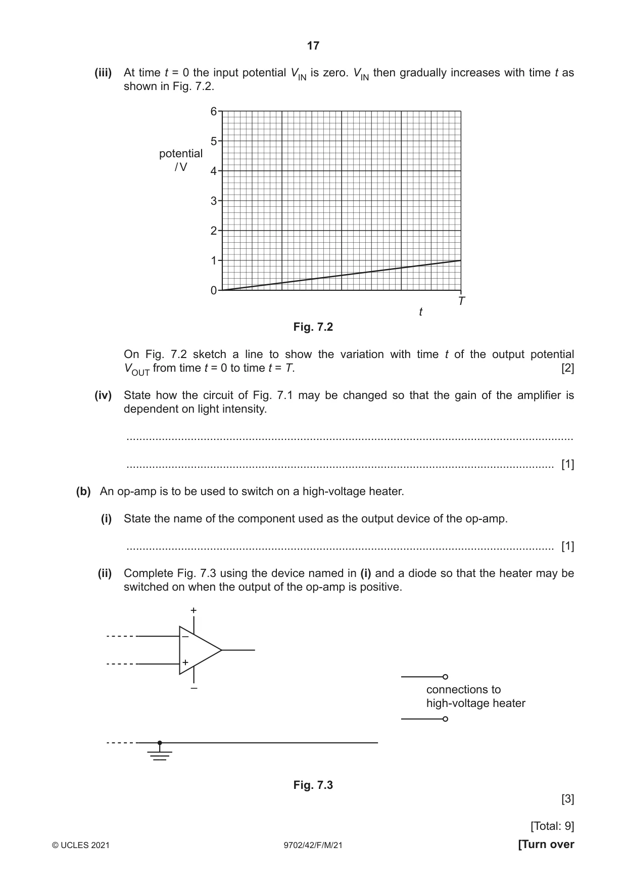
7 (a) Fig. 7.1 shows the circuit diagram containing an operational amplifier (op-amp). 3.6 kΩ + 3.0 V – + – 3.0 V VOUT VIN 0.72 kΩ Fig. 7.1 (i) State the name of this type of amplifier. ..................................................................................................................................... [1] (ii) Show that the gain of the amplifier is 6.0. [1] (iii) At time t = 0 the input potential VIN is zero. VIN then gradually increases with time t as shown in Fig. 7.2. 6 5 potential / V 4 3 2 1 0 T t Fig. 7.2 On Fig. 7.2 sketch a line to show the variation with time t of the output potential VOUT from time t = 0 to time t = T. [2] (iv) State how the circuit of Fig. 7.1 may be changed so that the gain of the amplifier is dependent on light intensity. ........................................................................................................................................... ..................................................................................................................................... [1] (b) An op-amp is to be used to switch on a high-voltage heater. (i) State the name of the component used as the output device of the op-amp. ..................................................................................................................................... [1] (ii) Complete Fig. 7.3 using the device named in (i) and a diode so that the heater may be switched on when the output of the op-amp is positive. + – + – connections to high-voltage heater Fig. 7.3 [3] [Total: 9]
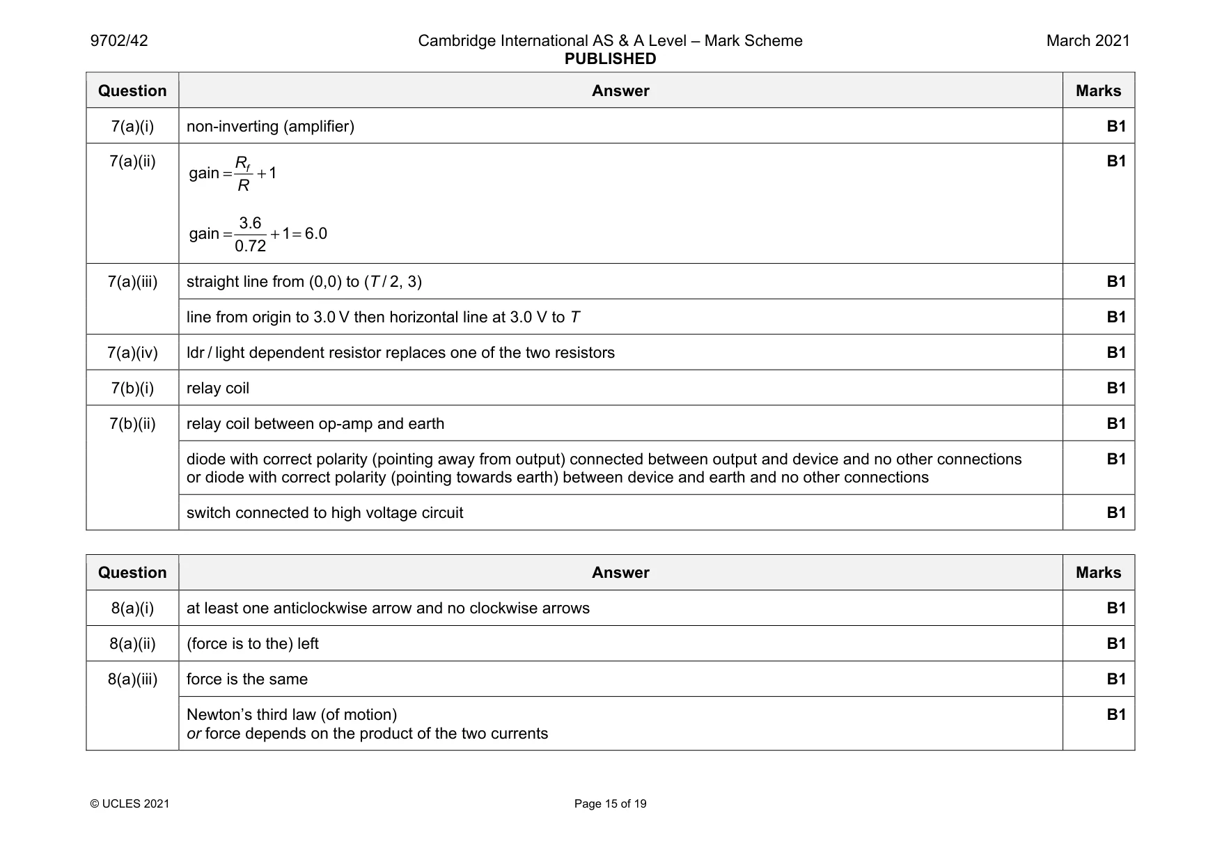
Mark scheme: 7(a)(i) non-inverting (amplifier) B1 7(a)(ii) gain 1 f R R = + 3.6 gain 1 6.0 0.72 = + = B1 7(a)(iii) straight line from (0,0) to (T / 2, 3) B1 line from origin to 3.0 V then horizontal line at 3.0 V to T B1 7(a)(iv) ldr / light dependent resistor replaces one of the two resistors B1 7(b)(i) relay coil B1 7(b)(ii) relay coil between op-amp and earth B1 diode with correct polarity (pointing away from output) connected between output and device and no other connections or diode with correct polarity (pointing towards earth) between device and earth and no other connections B1 switch connected to high voltage circuit B1
Q8 · Two long straight wires P and Q are parallel to each other, as shown in Fig
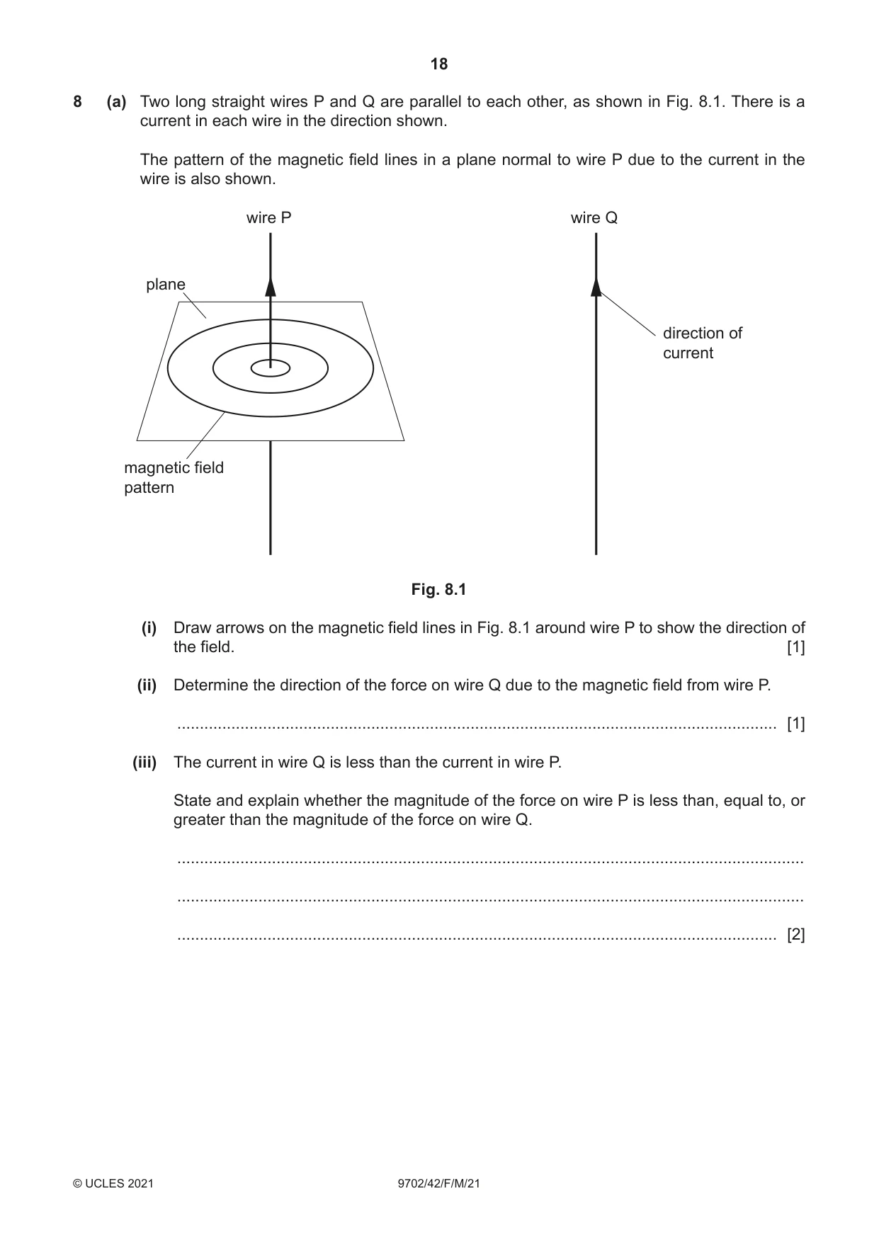
8 (a) Two long straight wires P and Q are parallel to each other, as shown in Fig. 8.1. There is a current in each wire in the direction shown. The pattern of the magnetic field lines in a plane normal to wire P due to the current in the wire is also shown. wire P wire Q plane direction of current magnetic field pattern Fig. 8.1 (i) Draw arrows on the magnetic field lines in Fig. 8.1 around wire P to show the direction of the field. [1] (ii) Determine the direction of the force on wire Q due to the magnetic field from wire P. ..................................................................................................................................... [1] (iii) The current in wire Q is less than the current in wire P. State and explain whether the magnitude of the force on wire P is less than, equal to, or greater than the magnitude of the force on wire Q. ........................................................................................................................................... ........................................................................................................................................... ..................................................................................................................................... [2] (b) Nuclear magnetic resonance imaging (NMRI) is used to obtain diagnostic information about internal structures in the human body. Radio waves are produced and directed towards the body. The radio waves affect the protons within the body. (i) Explain why radio waves are used. ........................................................................................................................................... ........................................................................................................................................... ..................................................................................................................................... [2] (ii) Explain why the radio waves are applied in pulses. ........................................................................................................................................... ........................................................................................................................................... ..................................................................................................................................... [2] [Total: 8]
Mark scheme: 8(a)(i) at least one anticlockwise arrow and no clockwise arrows B1 8(a)(ii) (force is to the) left B1 8(a)(iii) force is the same B1 Newton’s third law (of motion) or force depends on the product of the two currents B1 Question Answer Marks 8(b)(i) frequency of radio waves is equal to natural frequency of protons B1 resonance of protons occurs / protons absorb energy B1 8(b)(ii) in between pulses / when pulse stops B1 Any 1 from: • protons de-excite • protons emit r.f. pulses • emitted (r.f.) pulse (from proton) detected B1
Q9 · Define magnetic flux linkage
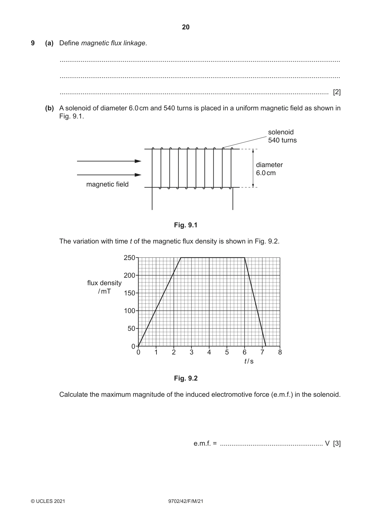
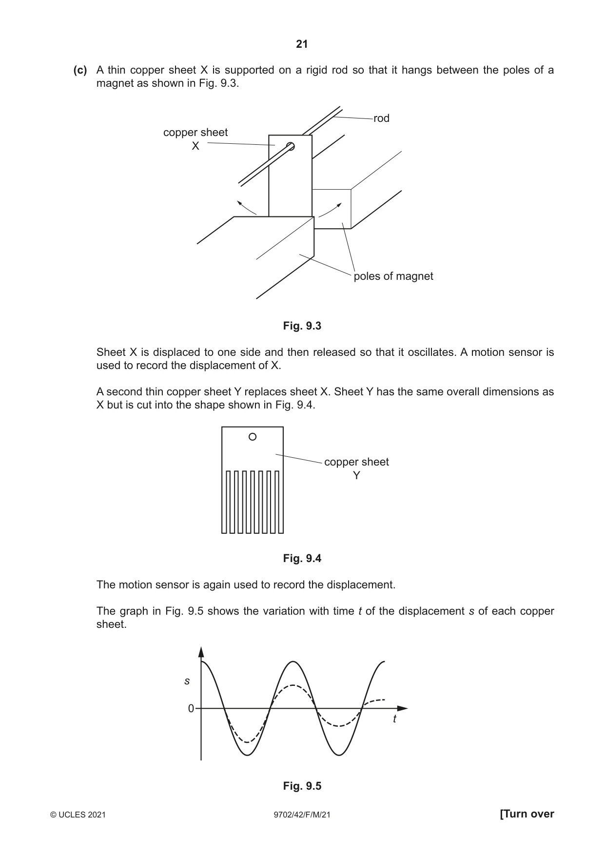
9 (a) Define magnetic flux linkage. ................................................................................................................................................... ................................................................................................................................................... ............................................................................................................................................. [2] (b) A solenoid of diameter 6.0 cm and 540 turns is placed in a uniform magnetic field as shown in Fig. 9.1. solenoid 540 turns diameter 6.0 cm magnetic field Fig. 9.1 The variation with time t of the magnetic flux density is shown in Fig. 9.2. 250 200 flux density / mT 150 100 50 0 0 1 2 3 4 5 6 7 8 t / s Fig. 9.2 Calculate the maximum magnitude of the induced electromotive force (e.m.f.) in the solenoid. e.m.f. = ...................................................... V [3] (c) A thin copper sheet X is supported on a rigid rod so that it hangs between the poles of a magnet as shown in Fig. 9.3. rod copper sheet X poles of magnet Fig. 9.3 Sheet X is displaced to one side and then released so that it oscillates. A motion sensor is used to record the displacement of X. A second thin copper sheet Y replaces sheet X. Sheet Y has the same overall dimensions as X but is cut into the shape shown in Fig. 9.4. copper sheet Y Fig. 9.4 The motion sensor is again used to record the displacement. The graph in Fig. 9.5 shows the variation with time t of the displacement s of each copper sheet. s 0 t Fig. 9.5 (i) State the name of the phenomenon illustrated by the gradual reduction in the amplitude of the dashed line. ..................................................................................................................................... [1] (ii) Deduce which copper sheet is represented by the dashed line. Explain your answer using the principles of electromagnetic induction. ........................................................................................................................................... ........................................................................................................................................... ........................................................................................................................................... ........................................................................................................................................... ........................................................................................................................................... ..................................................................................................................................... [4] [Total: 10]
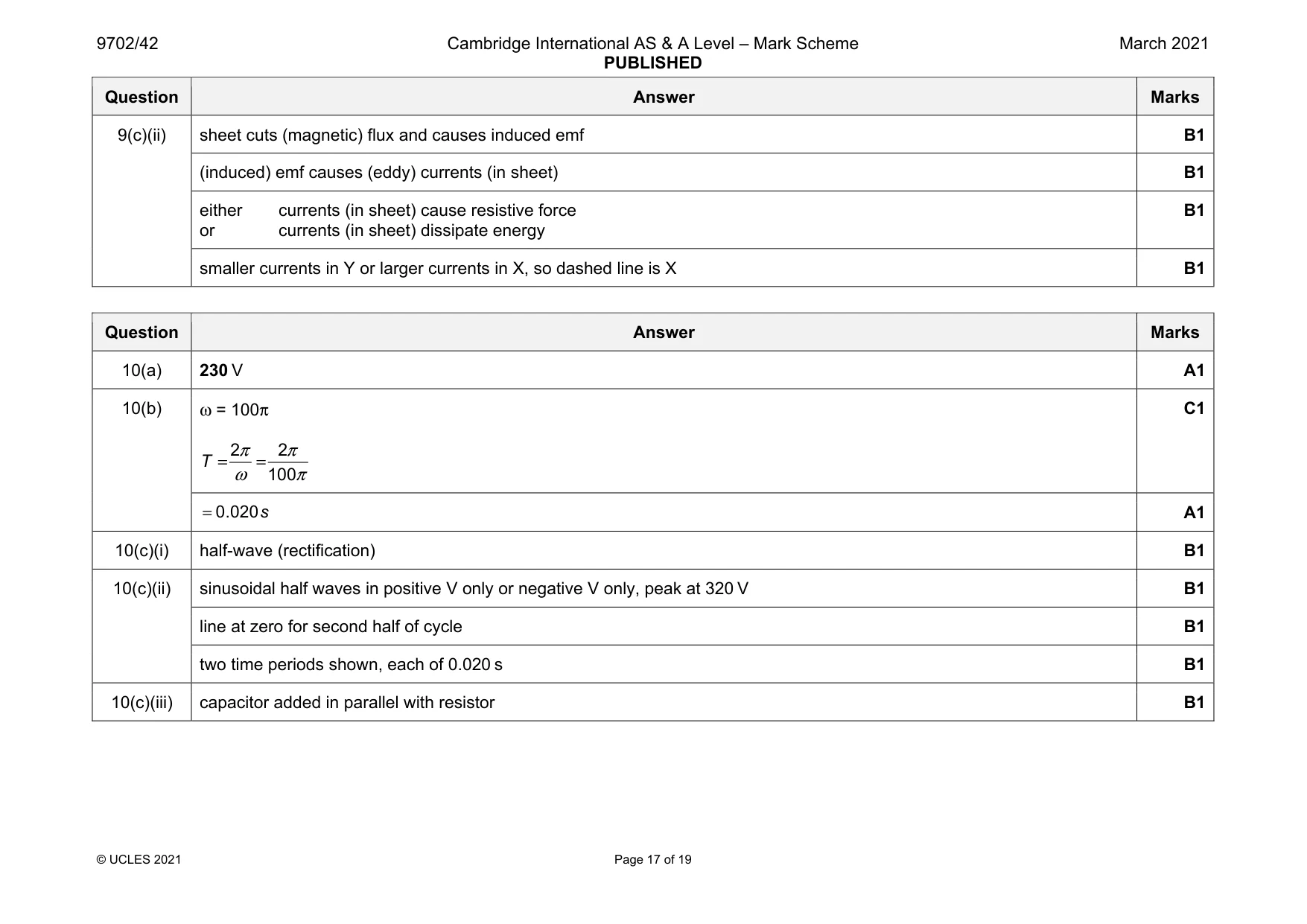
Mark scheme: 9(a) (magnetic) flux density × area × number of turns M1 area is perpendicular to (magnetic) field A1 9(b) use of t = 1.2 s C1 BAN t ε Δ = Δ 2 0.250 0.030 540 1.2 π × × × = C1 0.32 V = A1 9(c)(i) light damping B1 Question Answer Marks 9(c)(ii) sheet cuts (magnetic) flux and causes induced emf B1 (induced) emf causes (eddy) currents (in sheet) B1 either currents (in sheet) cause resistive force or currents (in sheet) dissipate energy B1 smaller currents in Y or larger currents in X, so dashed line is X B1
Q10 · The output potential difference (p.d.) of an alternating power supply is represented by V…
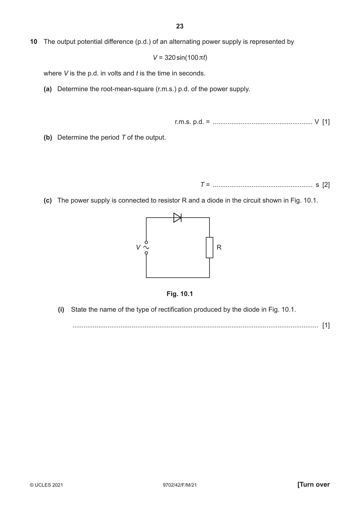
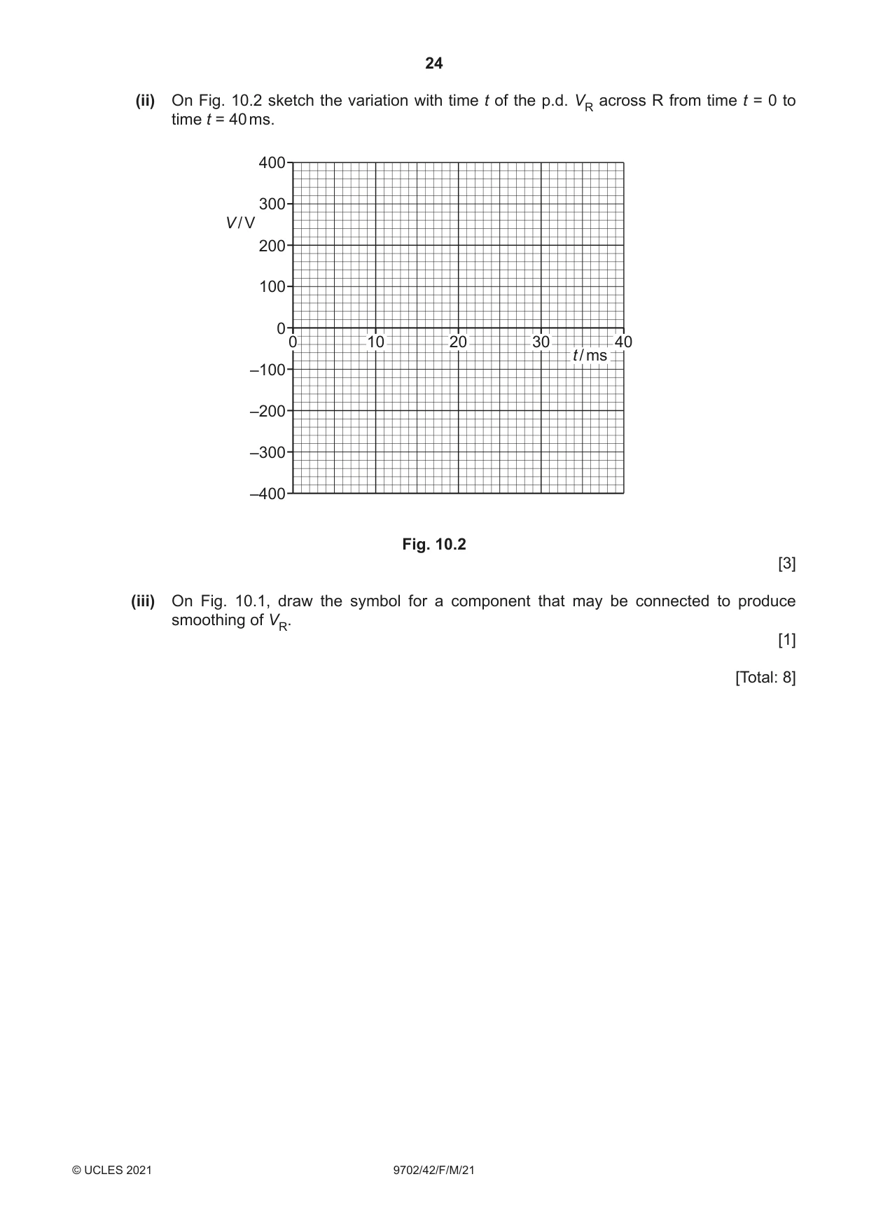
10 The output potential difference (p.d.) of an alternating power supply is represented by V = 320 sin(100 πt) where V is the p.d. in volts and t is the time in seconds. (a) Determine the root-mean-square (r.m.s.) p.d. of the power supply. r.m.s. p.d. = ...................................................... V [1] (b) Determine the period T of the output. T = ...................................................... s [2] (c) The power supply is connected to resistor R and a diode in the circuit shown in Fig. 10.1. V R Fig. 10.1 (i) State the name of the type of rectification produced by the diode in Fig. 10.1. ..................................................................................................................................... [1] (ii) On Fig. 10.2 sketch the variation with time t of the p.d. VR across R from time t = 0 to time t = 40 ms. 400 300 V / V 200 100 0 0 10 20 30 40 t / ms –100 –200 –300 –400 Fig. 10.2 [3] (iii) On Fig. 10.1, draw the symbol for a component that may be connected to produce smoothing of VR. [1] [Total: 8]
Mark scheme: 10(a) 230 V A1 10(b) ω = 100π 2 2 100 T π π ω π = = C1 0.020 s = A1 10(c)(i) half-wave (rectification) B1 10(c)(ii) sinusoidal half waves in positive V only or negative V only, peak at 320 V B1 line at zero for second half of cycle B1 two time periods shown, each of 0.020 s B1 10(c)(iii) capacitor added in parallel with resistor B1
Q11 · Electrons are accelerated through a potential difference of 15 kV
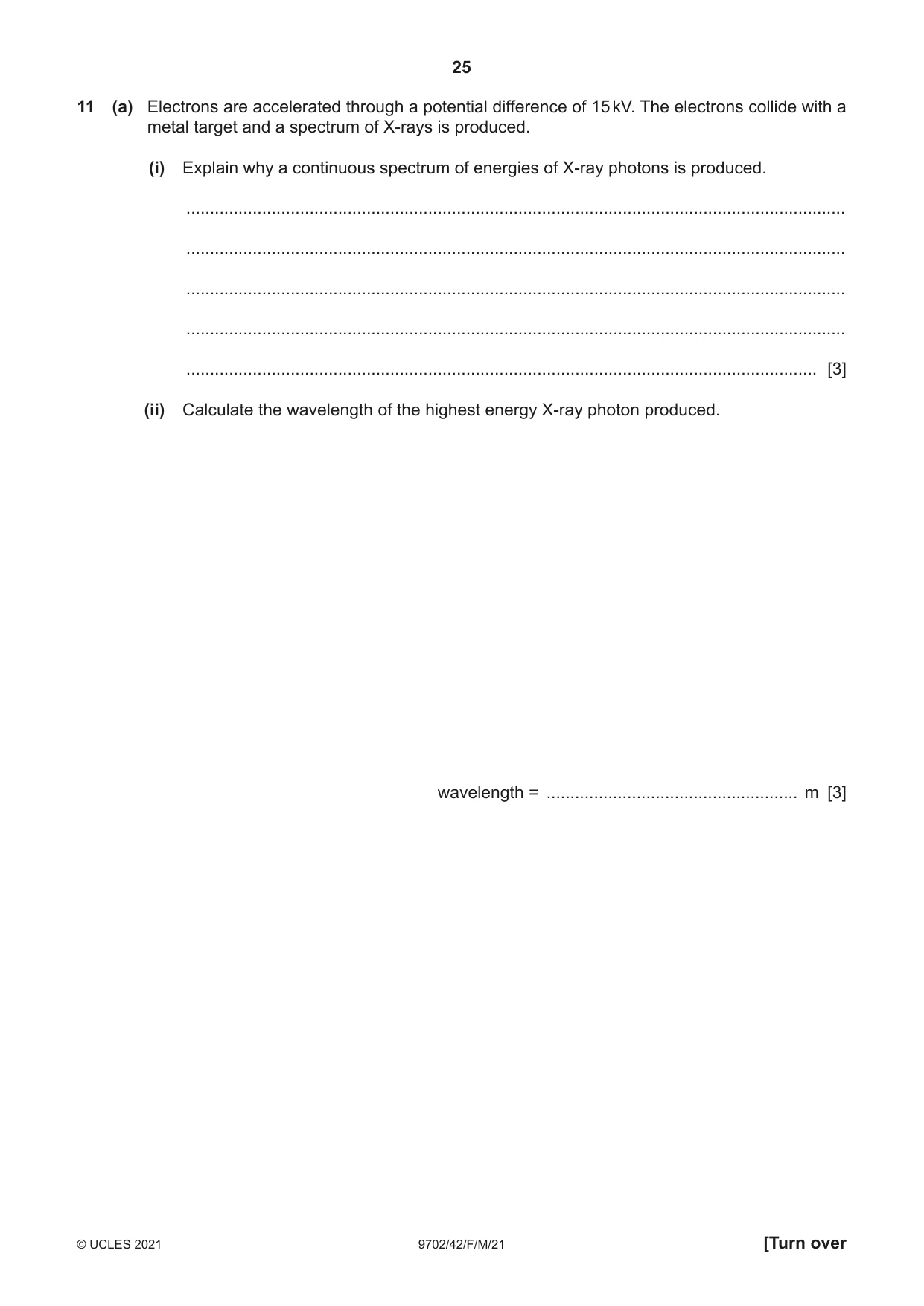
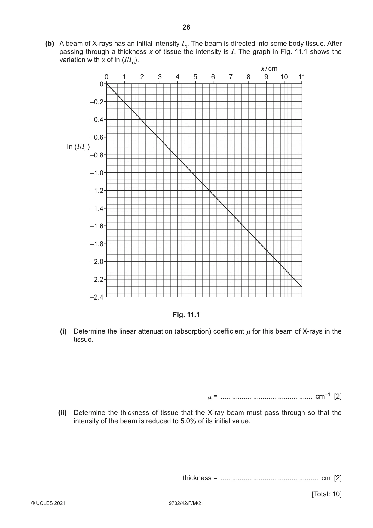
11 (a) Electrons are accelerated through a potential difference of 15 kV. The electrons collide with a metal target and a spectrum of X-rays is produced. (i) Explain why a continuous spectrum of energies of X-ray photons is produced. ........................................................................................................................................... ........................................................................................................................................... ........................................................................................................................................... ........................................................................................................................................... ..................................................................................................................................... [3] (ii) Calculate the wavelength of the highest energy X-ray photon produced. wavelength = ..................................................... m [3] (b) A beam of X-rays has an initial intensity Io. The beam is directed into some body tissue. After passing through a thickness x of tissue the intensity is I. The graph in Fig. 11.1 shows the variation with x of ln (I/Io). x / cm 0 1 2 3 4 5 6 7 8 9 10 11 0 –0.2 –0.4 –0.6 In (I/Io) –0.8 –1.0 –1.2 –1.4 –1.6 –1.8 –2.0 –2.2 –2.4 Fig. 11.1 (i) Determine the linear attenuation (absorption) coefficient μ for this beam of X-rays in the tissue. μ = ................................................ cm–1 [2] (ii) Determine the thickness of tissue that the X-ray beam must pass through so that the intensity of the beam is reduced to 5.0% of its initial value. thickness = ................................................... cm [2] [Total: 10]
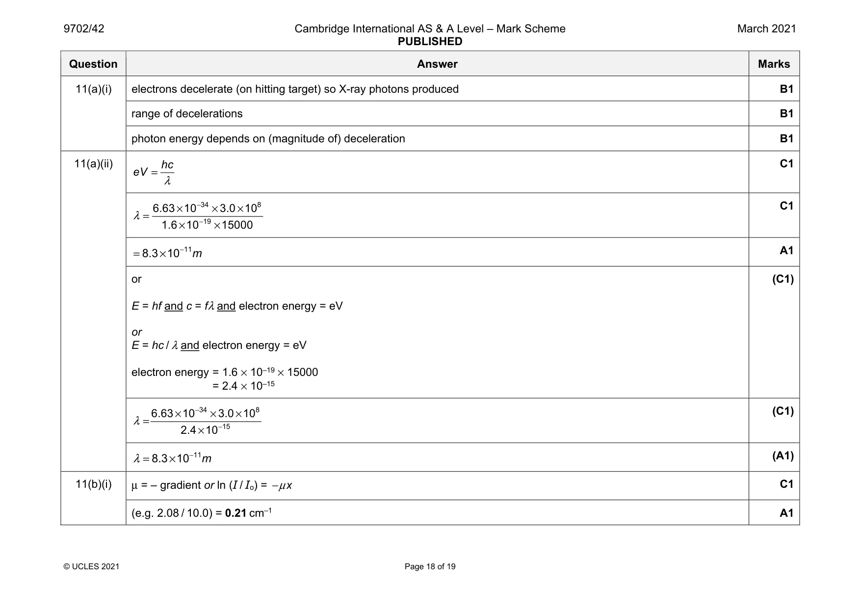
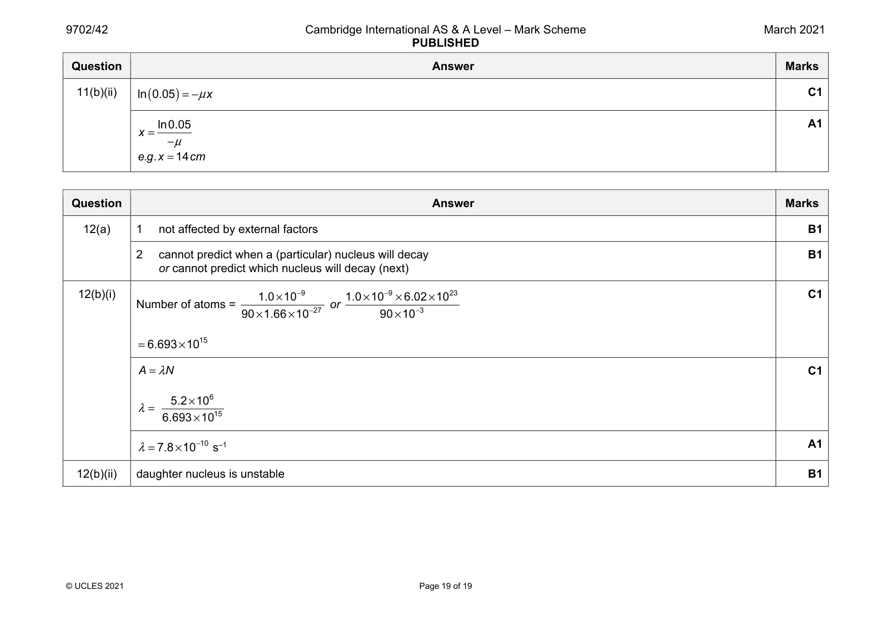
Mark scheme: 11(a)(i) electrons decelerate (on hitting target) so X-ray photons produced B1 range of decelerations B1 photon energy depends on (magnitude of) deceleration B1 11(a)(ii) hc eV λ = C1 34 8 19 6.63 10 3.0 10 1.6 10 15000 λ − − × × × = × × C1 11 8.3 10 m − = × A1 or E = hf and c = fλ and electron energy = eV or E = hc / λ and electron energy = eV electron energy = 1.6 × 10–19 × 15000 = 2.4 × 10⁻¹⁵ (C1) 34 8 15 6.63 10 3.0 10 2.4 10 λ − − × × × = × (C1) 11 8.3 10 m λ − = × (A1) 11(b)(i) μ = – gradient or ln (I / Io) = x μ − C1 (e.g. 2.08 / 10.0) = 0.21 cm–1 A1 Question Answer Marks 11(b)(ii) ( ) ln 0.05 x μ = − C1 ln0.05 x μ = − . . 14 e g x cm = A1
Q12 · Radioactive decay is both spontaneous and random
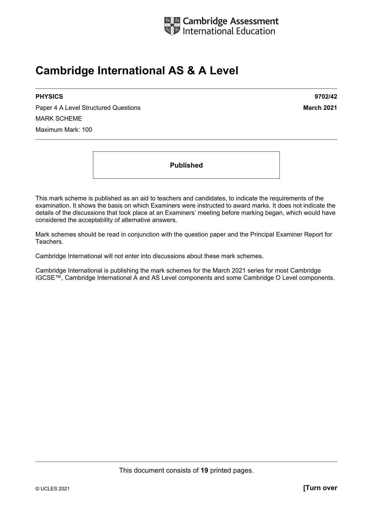
12 (a) Radioactive decay is both spontaneous and random. State what is meant by: 1. spontaneous decay ........................................................................................................... ........................................................................................................................................... 2. random decay. ................................................................................................................... ........................................................................................................................................... [2] (b) Strontium-90 (9038 Sr) is an unstable nuclide. The activity of a sample of 1.0 × 10⁻⁹ kg of strontium-90 is 5.2 MBq. (i) Determine the decay constant λ of strontium-90. λ = ................................................... s–1 [3] (ii) The activity of the sample after a time of 1.0 half lives is found to be greater than the expected 2.6 MBq. Suggest a possible reason for this. ........................................................................................................................................... ..................................................................................................................................... [1] [Total: 6]
Mark scheme: 12(a) 1 not affected by external factors B1 2 cannot predict when a (particular) nucleus will decay or cannot predict which nucleus will decay (next) B1 12(b)(i) Number of atoms = 9 27 1.0 10 90 1.66 10 − − × × × or 9 23 3 1.0 10 6.02 10 90 10 − − × × × × 15 6.693 10 = × C1 A N λ = λ = 6 15 5.2 10 6.693 10 × × C1 10 7.8 10 λ − = × s–1 A1 12(b)(ii) daughter nucleus is unstable B1
What was in this paper
The subtopics covered by these 12 questions, and how many questions each got. Open one in a new tab to see every Cambridge question on it.
1Electromagnetic induction1Electromagnetic spectrum1Equation of state1Gravitational potential1Magnetic fields due to currents1Practical circuits1Production and use of X-rays1Radioactive decay1Rectification and smoothing1Simple harmonic oscillations1Specific heat capacity and specific latent heat1What you needed in this session
Cambridge’s own grade thresholds for 2021 Feb/March, Paper 4 · Variant 2. A higher threshold means an easier paper — the bar moves with how the cohort did.