Questions as text
Q1 · An ideal transformer is shown in Fig 9702/42 Feb/March 2017
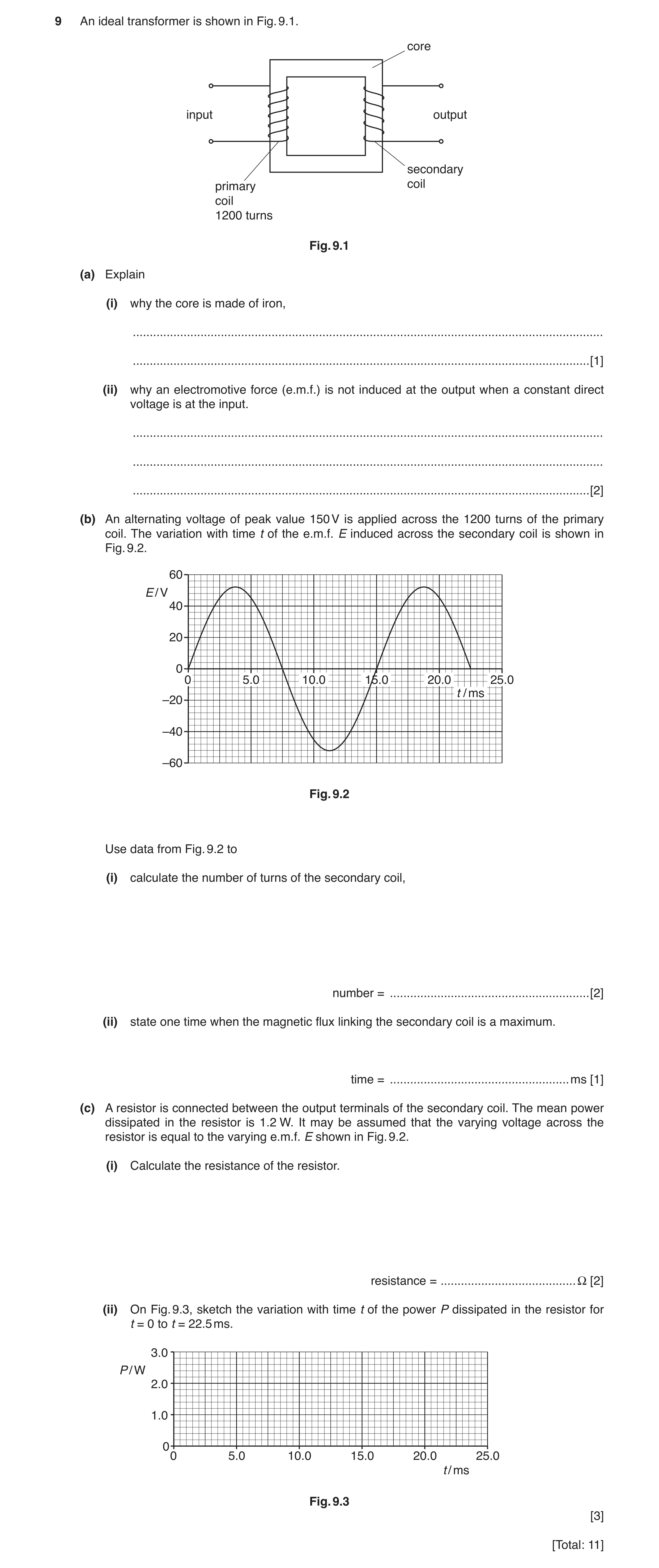
9 An ideal transformer is shown in Fig. 9.1. core input output secondary primary coil coil 1200 turns Fig. 9.1 (a) Explain (i) why the core is made of iron, … … [1] (ii) why an electromotive force (e.m.f.) is not induced at the output when a constant direct voltage is at the input. … … … [2] (b) An alternating voltage of peak value 150 V is applied across the 1200 turns of the primary coil. The variation with time t of the e.m.f. E induced across the secondary coil is shown in Fig. 9.2. 60 E / V 40 20 0 0 5.0 10.0 15.0 20.0 25.0 t / ms –20 –40 –60 Fig. 9.2 Use data from Fig. 9.2 to (i) calculate the number of turns of the secondary coil, number = … [2] (ii) state one time when the magnetic flux linking the secondary coil is a maximum. time = … ms [1] (c) A resistor is connected between the output terminals of the secondary coil. The mean power dissipated in the resistor is 1.2 W. It may be assumed that the varying voltage across the resistor is equal to the varying e.m.f. E shown in Fig. 9.2. (i) Calculate the resistance of the resistor. resistance = … Ω [2] (ii) On Fig. 9.3, sketch the variation with time t of the power P dissipated in the resistor for t = 0 to t = 22.5 ms. 3.0 P / W 2.0 1.0 0 0 5.0 10.0 15.0 20.0 25.0 t / ms Fig. 9.3 [3] [Total: 11]
11 marks
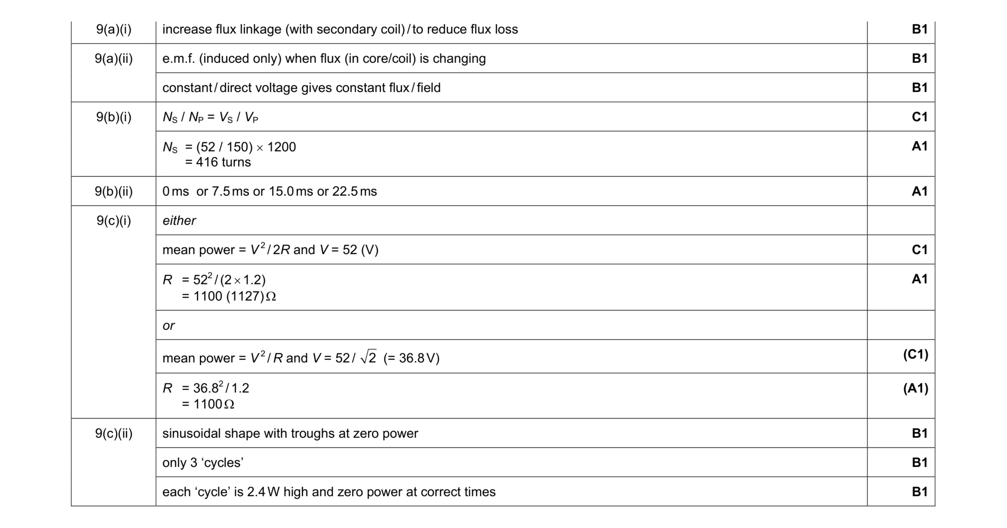
Mark scheme: 9(a)(i) increase flux linkage (with secondary coil) / to reduce flux loss B1 9(a)(ii) e.m.f. (induced only) when flux (in core/coil) is changing B1 constant / direct voltage gives constant flux / field B1 9(b)(i) NS / NP = VS / VP C1 NS = (52 / 150) × 1200 = 416 turns A1 9(b)(ii) 0 ms or 7.5 ms or 15.0 ms or 22.5 ms A1 9(c)(i) either mean power = V 2 / 2R and V = 52 (V) C1 R = 522 / (2 × 1.2) = 1100 (1127) Ω A1 or mean power = V 2 / R and V = 52 / 2 (= 36.8 V) (C1) R = 36.82 / 1.2 = 1100 Ω (A1) 9(c)(ii) sinusoidal shape with troughs at zero power B1 only 3 ‘cycles’ B1 each ‘cycle’ is 2.4 W high and zero power at correct times B1
This question in 9702/42 Feb/March 2017
Q2 · A simple transformer is illustrated in Fig 9702/41 May/June 2017
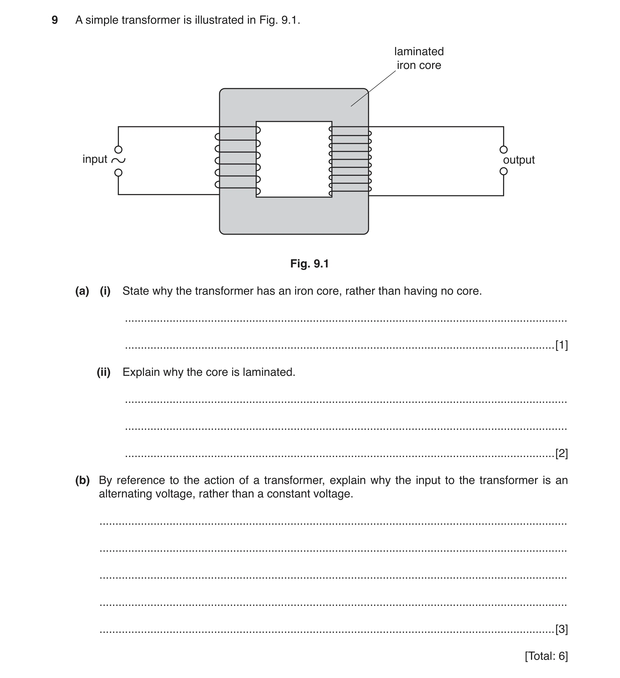
9 A simple transformer is illustrated in Fig. 9.1. laminated iron core input output Fig. 9.1 (a) (i) State why the transformer has an iron core, rather than having no core. … … [1] (ii) Explain why the core is laminated. … … … [2] (b) By reference to the action of a transformer, explain why the input to the transformer is an alternating voltage, rather than a constant voltage. … … … … … [3] [Total: 6]
6 marks
Mark scheme: 9(a)(i) core reduces loss of (magnetic) flux linkage/improves flux linkage B1 9(a)(ii) reduces (size of eddy) currents in core B1 (so that) heating of core is reduced B1 9(b) alternating voltage gives rise to changing magnetic flux in core M1 (changing) flux links the secondary coil A1 induced e.m.f. (in secondary) only when flux is changing/cut B1
This question in 9702/41 May/June 2017
Q3 · A simple transformer is illustrated in Fig 9702/43 May/June 2017
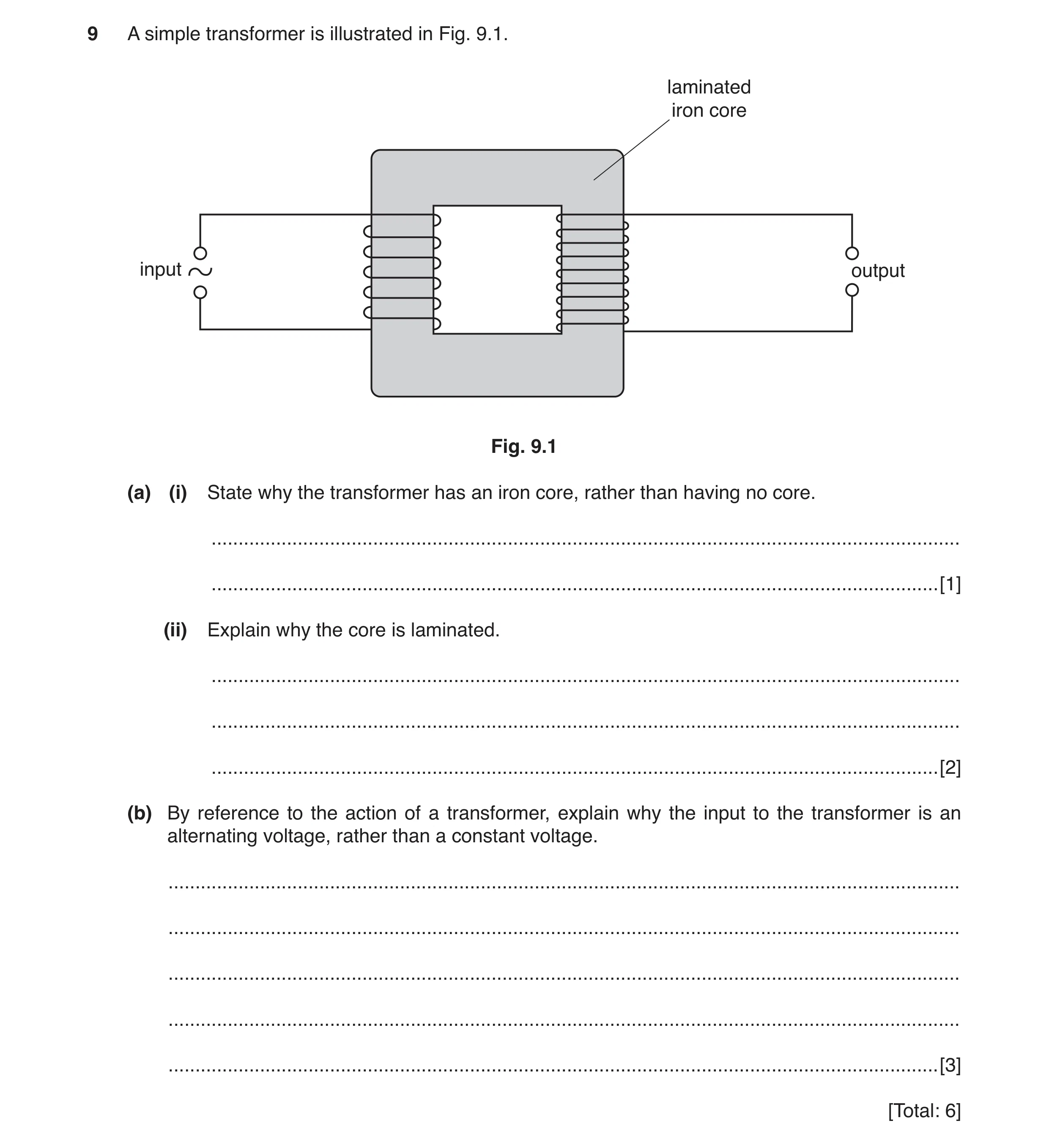
9 A simple transformer is illustrated in Fig. 9.1. laminated iron core input output Fig. 9.1 (a) (i) State why the transformer has an iron core, rather than having no core. … … [1] (ii) Explain why the core is laminated. … … … [2] (b) By reference to the action of a transformer, explain why the input to the transformer is an alternating voltage, rather than a constant voltage. … … … … … [3] [Total: 6]
6 marks
Mark scheme: 9(a)(i) core reduces loss of (magnetic) flux linkage/improves flux linkage B1 9(a)(ii) reduces (size of eddy) currents in core B1 (so that) heating of core is reduced B1 9(b) alternating voltage gives rise to changing magnetic flux in core M1 (changing) flux links the secondary coil A1 induced e.m.f. (in secondary) only when flux is changing/cut B1
This question in 9702/43 May/June 2017
Q4 · State Coulomb’s law for the force between two point charges 9702/41 Oct/Nov 2017
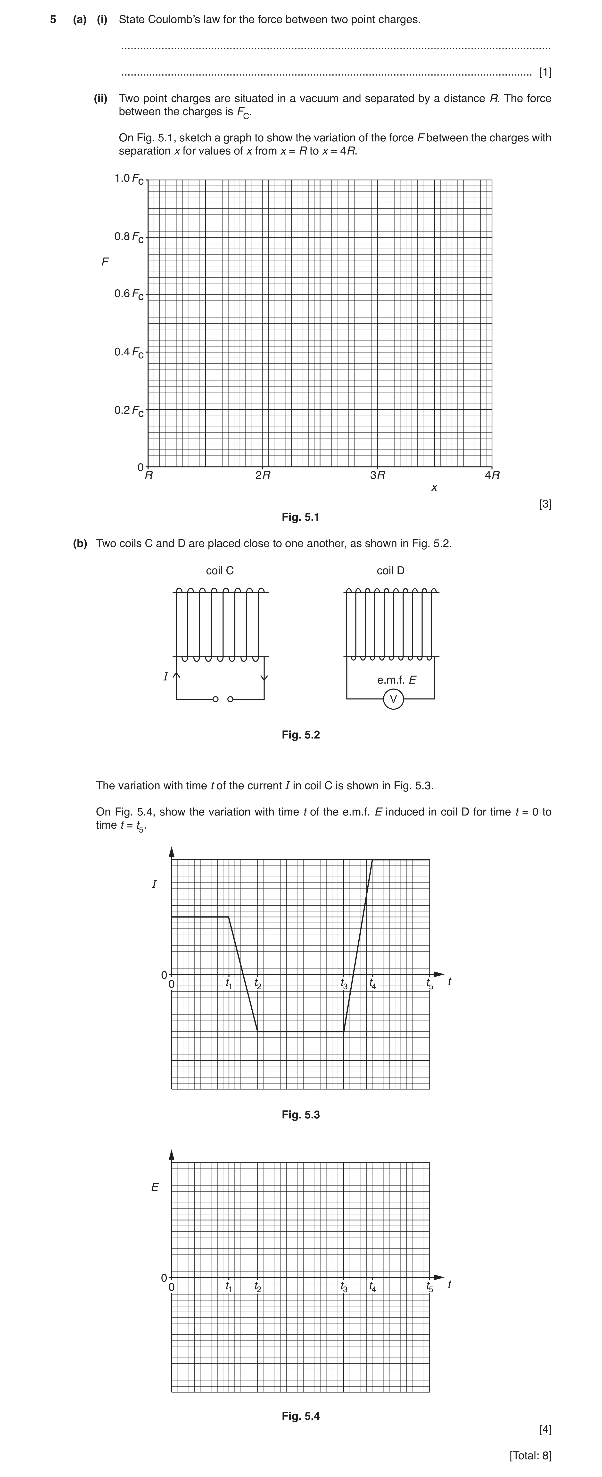
5 (a) (i) State Coulomb’s law for the force between two point charges. … … [1] (ii) Two point charges are situated in a vacuum and separated by a distance R. The force between the charges is FC. On Fig. 5.1, sketch a graph to show the variation of the force F between the charges with separation x for values of x from x = R to x = 4R. 1.0 Fc 0.8 Fc F 0.6 Fc 0.4 Fc 0.2 Fc 0 R 2R 3R 4R x [3] Fig. 5.1 (b) Two coils C and D are placed close to one another, as shown in Fig. 5.2. coil C coil D I e.m.f. E V Fig. 5.2 The variation with time t of the current I in coil C is shown in Fig. 5.3. On Fig. 5.4, show the variation with time t of the e.m.f. E induced in coil D for time t = 0 to time t = t5. I 0 0 t1 t2 t3 t4 t5 t Fig. 5.3 E 0 0 t1 t2 t3 t4 t5 t Fig. 5.4 [4] [Total: 8]
8 marks
Mark scheme: 5(a)(i) force proportional to product of charges and inversely proportional to square of separation A1 5(a)(ii) curve starting at (R, FC) B1 passing through (2R, 0.25FC) B1 passing through (4R, 0.06FC) B1 5(b) graph: E = 0 when current constant (0 to t1, t2 to t3, t4 to t5) B1 stepped from t1 to t2 and t3 to t4 B1 (steps) in opposite directions B1 later one larger in magnitude B1
This question in 9702/41 Oct/Nov 2017
Q5 · State Coulomb’s law for the force between two point charges 9702/43 Oct/Nov 2017
5 (a) (i) State Coulomb’s law for the force between two point charges. … … [1] (ii) Two point charges are situated in a vacuum and separated by a distance R. The force between the charges is FC. On Fig. 5.1, sketch a graph to show the variation of the force F between the charges with separation x for values of x from x = R to x = 4R. 1.0 Fc 0.8 Fc F 0.6 Fc 0.4 Fc 0.2 Fc 0 R 2R 3R 4R x [3] Fig. 5.1 (b) Two coils C and D are placed close to one another, as shown in Fig. 5.2. coil C coil D I e.m.f. E V Fig. 5.2 The variation with time t of the current I in coil C is shown in Fig. 5.3. On Fig. 5.4, show the variation with time t of the e.m.f. E induced in coil D for time t = 0 to time t = t5. I 0 0 t1 t2 t3 t4 t5 t Fig. 5.3 E 0 0 t1 t2 t3 t4 t5 t Fig. 5.4 [4] [Total: 8]
8 marks
Mark scheme: 5(a)(i) force proportional to product of charges and inversely proportional to square of separation A1 5(a)(ii) curve starting at (R, FC) B1 passing through (2R, 0.25FC) B1 passing through (4R, 0.06FC) B1 5(b) graph: E = 0 when current constant (0 to t1, t2 to t3, t4 to t5) B1 stepped from t1 to t2 and t3 to t4 B1 (steps) in opposite directions B1 later one larger in magnitude B1
This question in 9702/43 Oct/Nov 2017
Question 6 9702/42 Feb/March 2018
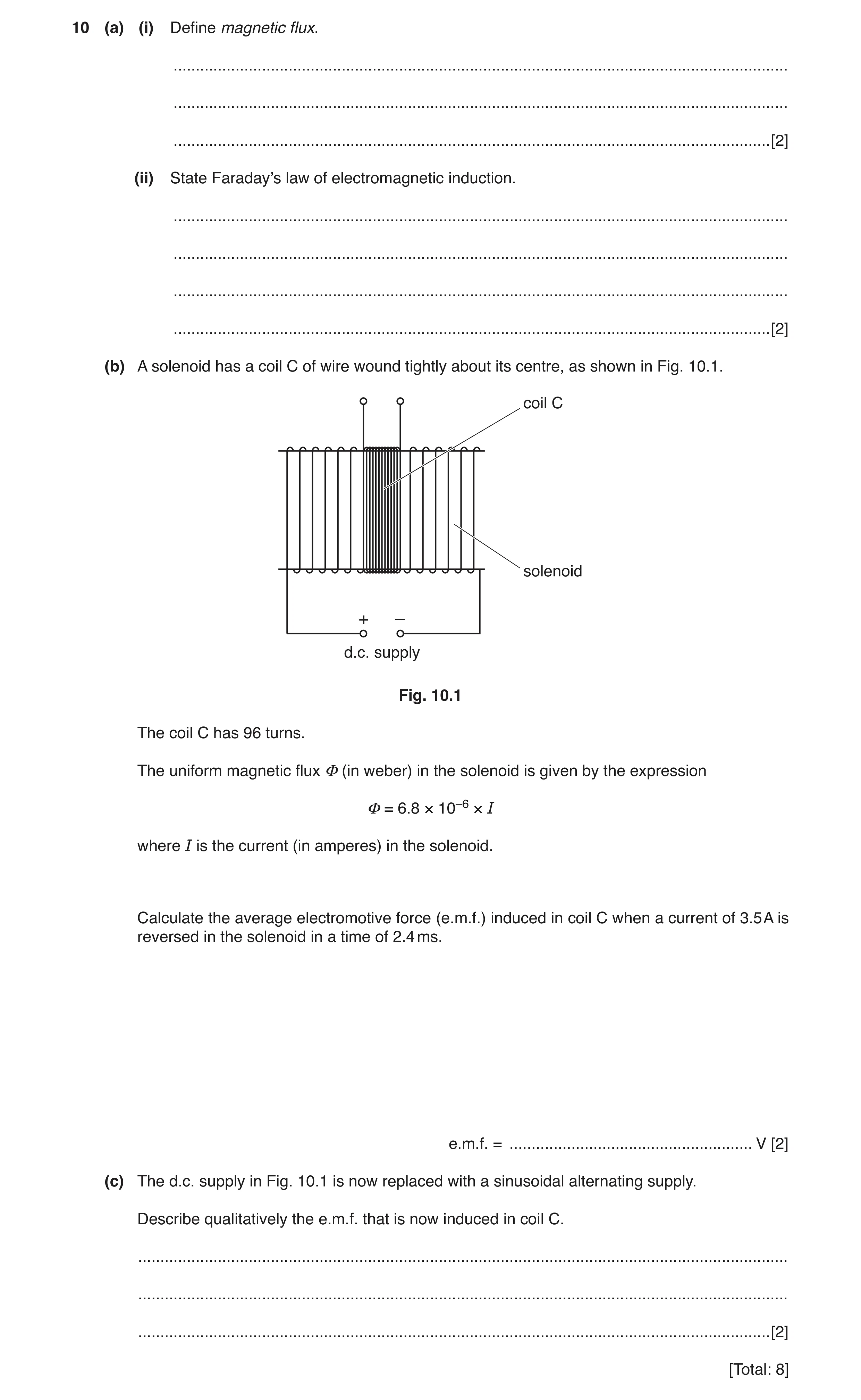
10 (a) (i) Define magnetic flux. … … … [2] (ii) State Faraday’s law of electromagnetic induction. … … … … [2] (b) A solenoid has a coil C of wire wound tightly about its centre, as shown in Fig. 10.1. coil C solenoid + – d.c. supply Fig. 10.1 The coil C has 96 turns. The uniform magnetic flux Φ (in weber) in the solenoid is given by the expression Φ = 6.8 × 10⁻⁶ × I where I is the current (in amperes) in the solenoid. Calculate the average electromotive force (e.m.f.) induced in coil C when a current of 3.5 A is reversed in the solenoid in a time of 2.4 ms. e.m.f. = … V [2] (c) The d.c. supply in Fig. 10.1 is now replaced with a sinusoidal alternating supply. Describe qualitatively the e.m.f. that is now induced in coil C. … … … [2] [Total: 8]
8 marks
Mark scheme: 10(a)(i) either product of flux density and area M1 direction of flux normal to area A1 or flux density × area × sinθ (M1) where θ is angle between direction of flux and area (A1) 10(a)(ii) (induced) e.m.f. proportional to rate M1 of change of (magnetic) flux linkage A1 10(b) e.m.f. = ∆( φN) / ∆t = (6.8 × 10–6 × 2 × 3.5 × 96) / (2.4 × 10⁻³) C1 = 1.9 V A1 Question Answer Marks 10(c) alternating C1 with same frequency as supply A1
This question in 9702/42 Feb/March 2018
Q7 · State Faraday’s law of electromagnetic induction 9702/41 May/June 2018
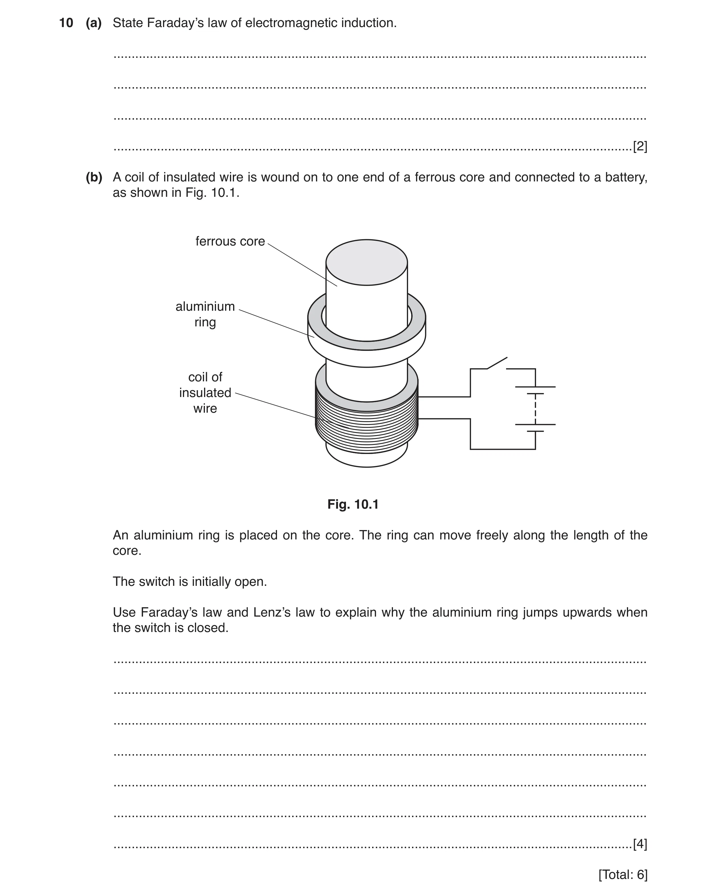
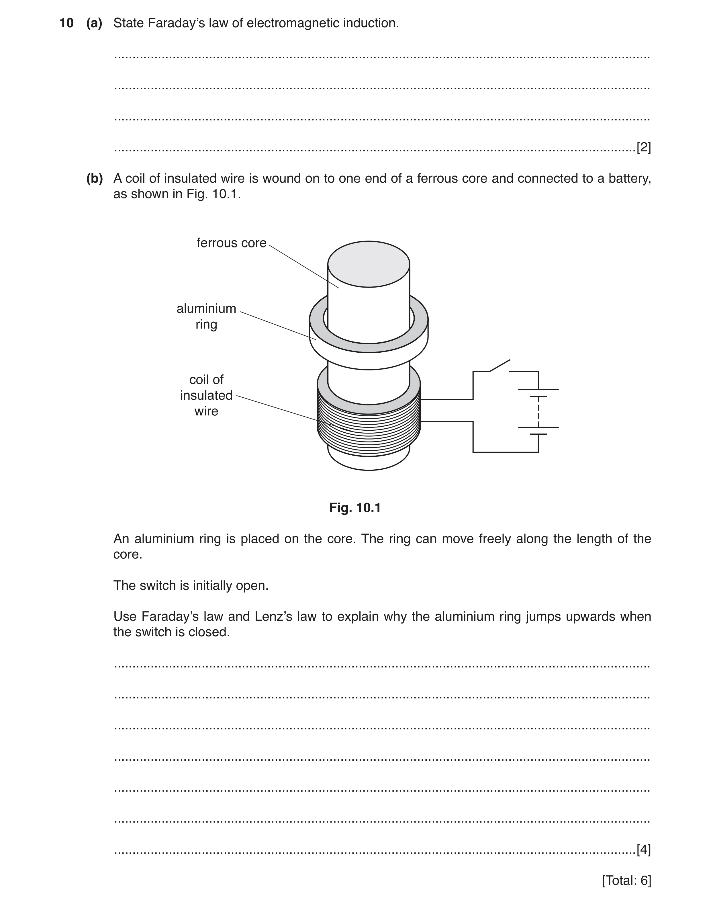
10 (a) State Faraday’s law of electromagnetic induction. … … … … [2] (b) A coil of insulated wire is wound on to one end of a ferrous core and connected to a battery, as shown in Fig. 10.1. ferrous core aluminium ring coil of insulated wire Fig. 10.1 An aluminium ring is placed on the core. The ring can move freely along the length of the core. The switch is initially open. Use Faraday’s law and Lenz’s law to explain why the aluminium ring jumps upwards when the switch is closed. … … … … … … … [4] [Total: 6]
6 marks
Mark scheme: 10(a) induced e.m.f. proportional to rate M1 of change of (magnetic) flux (linkage) or of cutting (magnetic) flux A1 10(b) current in coil produces flux B1 (by Faraday’s law) changing flux induces e.m.f. in ring B1 current in ring causes field (around ring) B1 (by Lenz’s law) field around ring opposes field around coil B1
This question in 9702/41 May/June 2018
Q8 · State what is meant by the magnetic flux linkage of a coil 9702/42 May/June 2018
9 (a) State what is meant by the magnetic flux linkage of a coil. … … … … [3] (b) A coil of wire has 160 turns and diameter 2.4 cm. The coil is situated in a uniform magnetic field of flux density 7.5 mT, as shown in Fig. 9.1. magnetic field flux density 2.4 cm 7.5 mT coil 160 turns Fig. 9.1 The direction of the magnetic field is along the axis of the coil. The magnetic flux density is reduced to zero in a time of 0.15 s. Show that the average e.m.f. induced in the coil is 3.6 mV. [2] (c) The magnetic flux density B in the coil in (b) is now varied with time t as shown in Fig. 9.2. 10 B / mT 5 0 0 0.1 0.2 0.3 0.4 0.5 0.6 t / s –5 –10 Fig. 9.2 Use data in (b) to show, on Fig. 9.3, the variation with time t of the e.m.f. E induced in the coil. 8 E / mV 6 4 2 0 0 0.1 0.2 0.3 0.4 0.5 0.6 t / s –2 –4 –6 –8 Fig. 9.3 [4] [Total: 9]
9 marks
Mark scheme: 9(a) B1 magnetic flux density normal to area or reference to cross-sectional area or × sin (angle between B and A) B1 × number of turns on coil B1 9(b) e.m.f. = BAN / t or e.m.f = rate of change of flux linkage C1 = (7.5 × 10⁻³ × π × {1.2 × 10⁻²}2 × 160) / 0.15 = 3.6 × 10⁻³ V A1 9(c) sketch: zero for 0–0.10 s, 0.25–0.35 s, and 0.425–0.55 s, and non-zero outside these ranges B1 two horizontal steps, with zero voltage either side B1 with same polarity B1 correct values (1st step 3.6 mV and 2nd step 7.2 mV) B1
This question in 9702/42 May/June 2018
Q9 · State Faraday’s law of electromagnetic induction 9702/43 May/June 2018
10 (a) State Faraday’s law of electromagnetic induction. … … … … [2] (b) A coil of insulated wire is wound on to one end of a ferrous core and connected to a battery, as shown in Fig. 10.1. ferrous core aluminium ring coil of insulated wire Fig. 10.1 An aluminium ring is placed on the core. The ring can move freely along the length of the core. The switch is initially open. Use Faraday’s law and Lenz’s law to explain why the aluminium ring jumps upwards when the switch is closed. … … … … … … … [4] [Total: 6]
6 marks
Mark scheme: 10(a) induced e.m.f. proportional to rate M1 of change of (magnetic) flux (linkage) or of cutting (magnetic) flux A1 10(b) current in coil produces flux B1 (by Faraday’s law) changing flux induces e.m.f. in ring B1 current in ring causes field (around ring) B1 (by Lenz’s law) field around ring opposes field around coil B1
This question in 9702/43 May/June 2018
Q10 · State Faraday’s law of electromagnetic induction 9702/41 Oct/Nov 2018
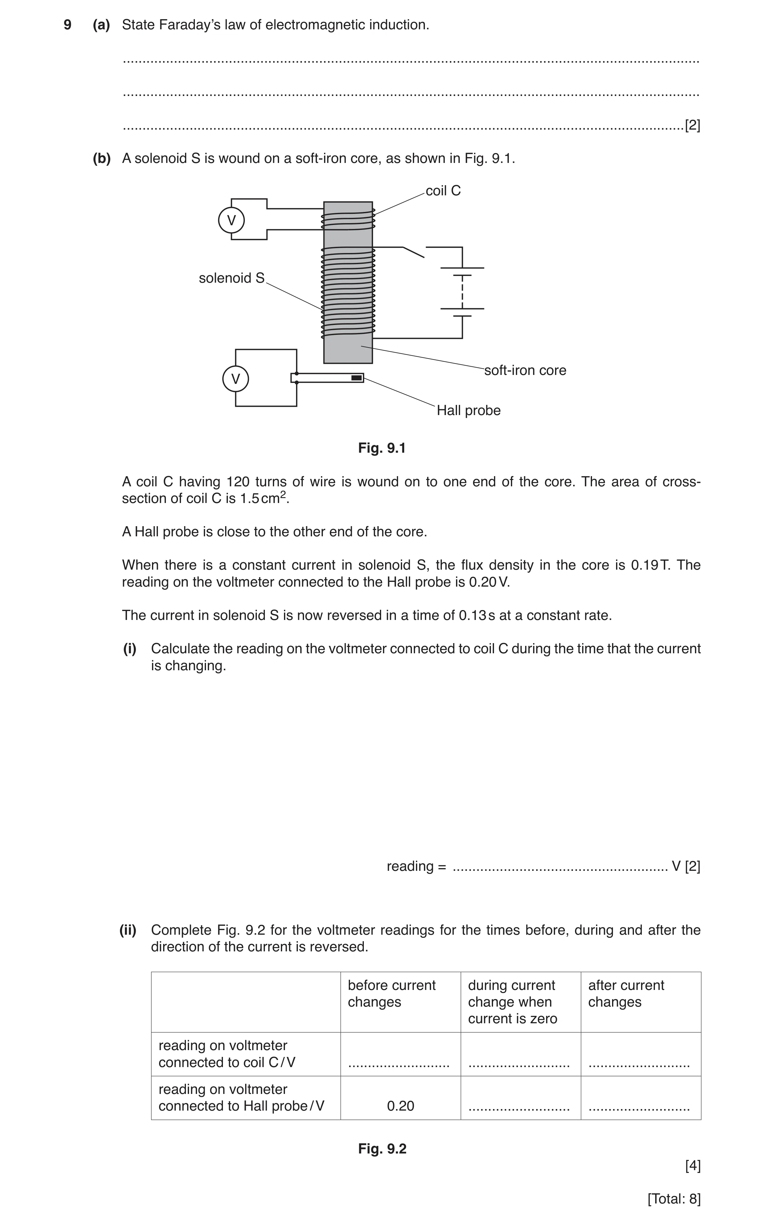
9 (a) State Faraday’s law of electromagnetic induction. … … … [2] (b) A solenoid S is wound on a soft-iron core, as shown in Fig. 9.1. coil C V solenoid S soft-iron core V Hall probe Fig. 9.1 A coil C having 120 turns of wire is wound on to one end of the core. The area of cross- section of coil C is 1.5 cm2. A Hall probe is close to the other end of the core. When there is a constant current in solenoid S, the flux density in the core is 0.19 T. The reading on the voltmeter connected to the Hall probe is 0.20 V. The current in solenoid S is now reversed in a time of 0.13 s at a constant rate. (i) Calculate the reading on the voltmeter connected to coil C during the time that the current is changing. reading = … V [2] (ii) Complete Fig. 9.2 for the voltmeter readings for the times before, during and after the direction of the current is reversed. before current during current after current changes change when changes current is zero reading on voltmeter connected to coil C / V … … … reading on voltmeter connected to Hall probe / V 0.20 … … Fig. 9.2 [4] [Total: 8]
8 marks
Mark scheme: 9(a) (induced) e.m.f. proportional/equal to rate M1 of change of (magnetic) flux (linkage) A1 9(b)(i) induced e.m.f. = (∆B)AN / ∆t = (2 × 0.19 × 1.5 × 10–4 × 120) / 0.13 C1 = 0.053 V A1 9(b)(ii) reading on voltmeter connected to coil C / V: 0 0.053 0 (all three values required) A1 reading on voltmeter connected to Hall probe / V: zero in middle column B1 final column correct sign (negative) B1 final column correct magnitude (0.20) B1
This question in 9702/41 Oct/Nov 2018
Q11 · A Hall probe is placed near one end of a solenoid that has been wound on a soft-iron… 9702/42 Oct/Nov 2018
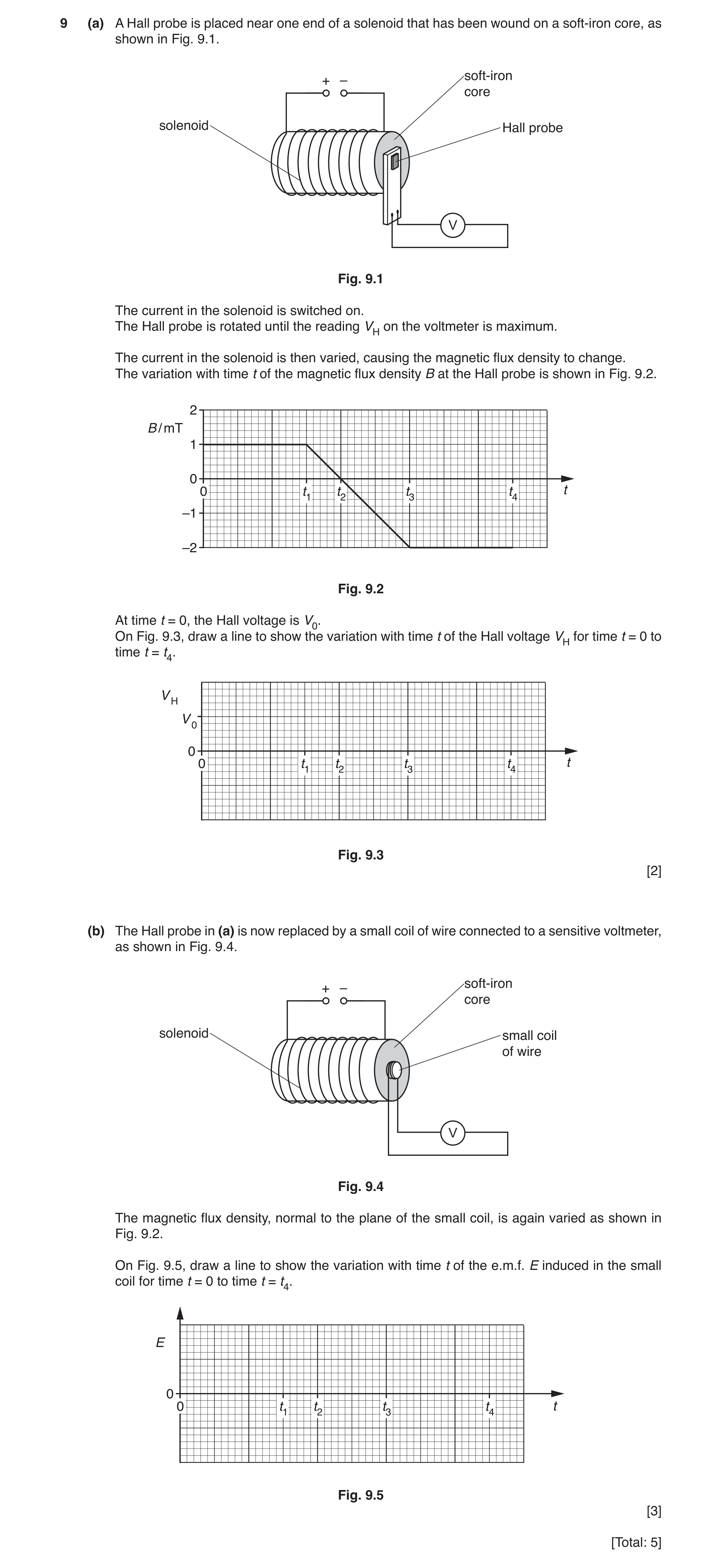
9 (a) A Hall probe is placed near one end of a solenoid that has been wound on a soft-iron core, as shown in Fig. 9.1. soft-iron + – core solenoid Hall probe V Fig. 9.1 The current in the solenoid is switched on. The Hall probe is rotated until the reading VH on the voltmeter is maximum. The current in the solenoid is then varied, causing the magnetic flux density to change. The variation with time t of the magnetic flux density B at the Hall probe is shown in Fig. 9.2. 2 B / mT 1 0 0 t1 t2 t3 t4 t –1 –2 Fig. 9.2 At time t = 0, the Hall voltage is V0. On Fig. 9.3, draw a line to show the variation with time t of the Hall voltage VH for time t = 0 to time t = t4. V H V 0 0 0 t1 t2 t3 t4 t Fig. 9.3 [2] (b) The Hall probe in (a) is now replaced by a small coil of wire connected to a sensitive voltmeter, as shown in Fig. 9.4. soft-iron + – core solenoid small coil of wire V Fig. 9.4 The magnetic flux density, normal to the plane of the small coil, is again varied as shown in Fig. 9.2. On Fig. 9.5, draw a line to show the variation with time t of the e.m.f. E induced in the small coil for time t = 0 to time t = t4. E 0 0 t1 t2 t3 t4 t Fig. 9.5 [3] [Total: 5]
5 marks
Mark scheme: 9(a) and t3 → t4 horizontal straight line at different non-zero VH B1 t1 → t3 straight diagonal line with negative gradient and graph line starts at (0, V0) and ends at (t4, –2V0) B1 9(b) E = 0 for 0 → t1 and t3 → t4 B1 E is non-zero at all points between t1 → t3 M1 E has constant magnitude between t1 → t3 A1
This question in 9702/42 Oct/Nov 2018
Q12 · State Faraday’s law of electromagnetic induction 9702/43 Oct/Nov 2018
9 (a) State Faraday’s law of electromagnetic induction. … … … [2] (b) A solenoid S is wound on a soft-iron core, as shown in Fig. 9.1. coil C V solenoid S soft-iron core V Hall probe Fig. 9.1 A coil C having 120 turns of wire is wound on to one end of the core. The area of cross- section of coil C is 1.5 cm2. A Hall probe is close to the other end of the core. When there is a constant current in solenoid S, the flux density in the core is 0.19 T. The reading on the voltmeter connected to the Hall probe is 0.20 V. The current in solenoid S is now reversed in a time of 0.13 s at a constant rate. (i) Calculate the reading on the voltmeter connected to coil C during the time that the current is changing. reading = … V [2] (ii) Complete Fig. 9.2 for the voltmeter readings for the times before, during and after the direction of the current is reversed. before current during current after current changes change when changes current is zero reading on voltmeter connected to coil C / V … … … reading on voltmeter connected to Hall probe / V 0.20 … … Fig. 9.2 [4] [Total: 8]
8 marks
Mark scheme: 9(a) (induced) e.m.f. proportional/equal to rate M1 of change of (magnetic) flux (linkage) A1 9(b)(i) induced e.m.f. = (∆B)AN / ∆t = (2 × 0.19 × 1.5 × 10–4 × 120) / 0.13 C1 = 0.053 V A1 9(b)(ii) reading on voltmeter connected to coil C / V: 0 0.053 0 (all three values required) A1 reading on voltmeter connected to Hall probe / V: zero in middle column B1 final column correct sign (negative) B1 final column correct magnitude (0.20) B1
This question in 9702/43 Oct/Nov 2018
Q13 · A cross-section through a current-carrying solenoid is shown in Fig 9702/42 Feb/March 2019
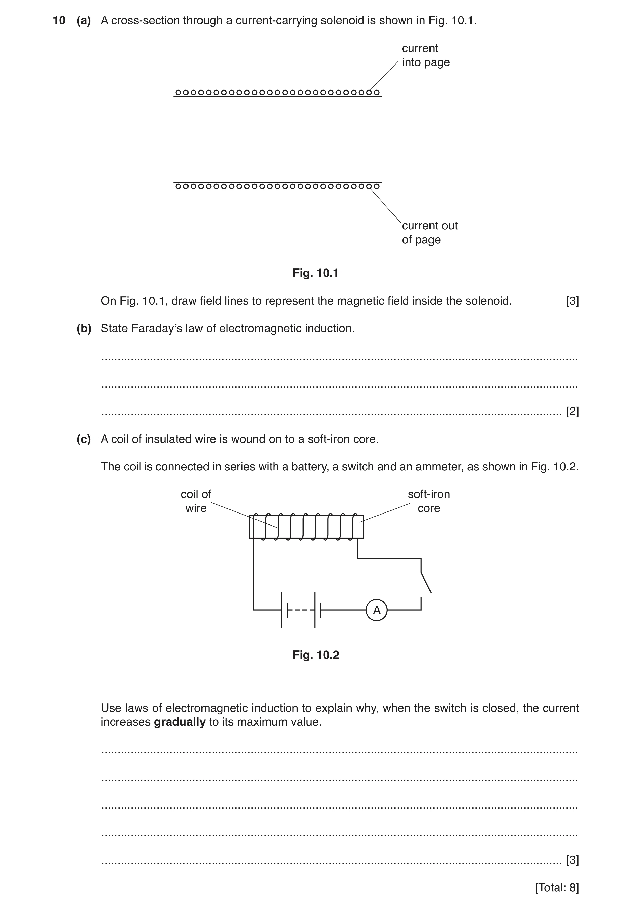
10 (a) A cross-section through a current-carrying solenoid is shown in Fig. 10.1. current into page current out of page Fig. 10.1 On Fig. 10.1, draw field lines to represent the magnetic field inside the solenoid. [3] (b) State Faraday’s law of electromagnetic induction. … … … [2] (c) A coil of insulated wire is wound on to a soft-iron core. The coil is connected in series with a battery, a switch and an ammeter, as shown in Fig. 10.2. coil of soft-iron wire core A Fig. 10.2 Use laws of electromagnetic induction to explain why, when the switch is closed, the current increases gradually to its maximum value. … … … … … [3] [Total: 8]
8 marks
Mark scheme: 10(a) single straight line along full length of solenoid B1 at least two more parallel lines along full length of solenoid B1 correct direction – right to left B1 10(b) (induced) e.m.f. proportional / equal to rate M1 of change of (magnetic) flux (linkage) A1 10(c) increasing current causes increasing flux B1 increasing flux induces e.m.f. in coil B1 (induced) e.m.f. opposes growth of current B1
This question in 9702/42 Feb/March 2019
Q14 · A solenoid is connected in series with a battery and a switch, as illustrated in Fig 9702/41 May/June 2019
8 A solenoid is connected in series with a battery and a switch, as illustrated in Fig. 8.1. small coil A solenoid axis of solenoid Fig. 8.1 A small coil, connected to a sensitive ammeter, is situated near one end of the solenoid. As the current in the solenoid is switched on, there is a changing magnetic field inside the solenoid. (a) (i) State what is meant by a magnetic field. … … [1] (ii) On Fig. 8.1, draw an arrow on the axis of the solenoid to show the direction of the magnetic field inside the solenoid. Label this arrow P. [1] (b) As the current in the solenoid is switched on, there is a current induced in the small coil. This induced current gives rise to a magnetic field in the small coil. (i) State Lenz’s law. … … … [2] (ii) Use Lenz’s law to state and explain the direction of the magnetic field due to the induced current in the small coil. On Fig. 8.1, mark this direction with an arrow inside the small coil. … … … … [3] (c) The small coil has an area of cross-section 7.0 × 10⁻⁴ m2 and contains 75 turns of wire. A constant current in the solenoid produces a uniform magnetic flux of flux density 1.4 mT throughout the small coil. The direction of the current in the solenoid is reversed in a time of 0.12 s. Calculate the average e.m.f. induced in the small coil. e.m.f. = … V [3] [Total: 10]
10 marks
Mark scheme: 8(a)(i) region where a force is exerted on: a magnetic pole or a moving charge or a current-carrying wire B1 8(a)(ii) arrow on axis of solenoid pointing downwards labelled P B1 8(b)(i) direction of induced e.m.f./current M1 (tends to) oppose the change causing it A1 8(b)(ii) magnetic field in solenoid is increasing B1 field in coil in opposite direction to oppose increase B1 arrow inside or just above small coil pointing in opposite direction to P B1 8(c) e.m.f. = N∆φ / ∆t C1 = (75 × 1.4 × 10–3 × 2 × 7.0 × 10–4) / 0.12 C1 = 1.2 × 10⁻³ V A1
This question in 9702/41 May/June 2019
Q15 · State Faraday’s law of electromagnetic induction 9702/42 May/June 2019
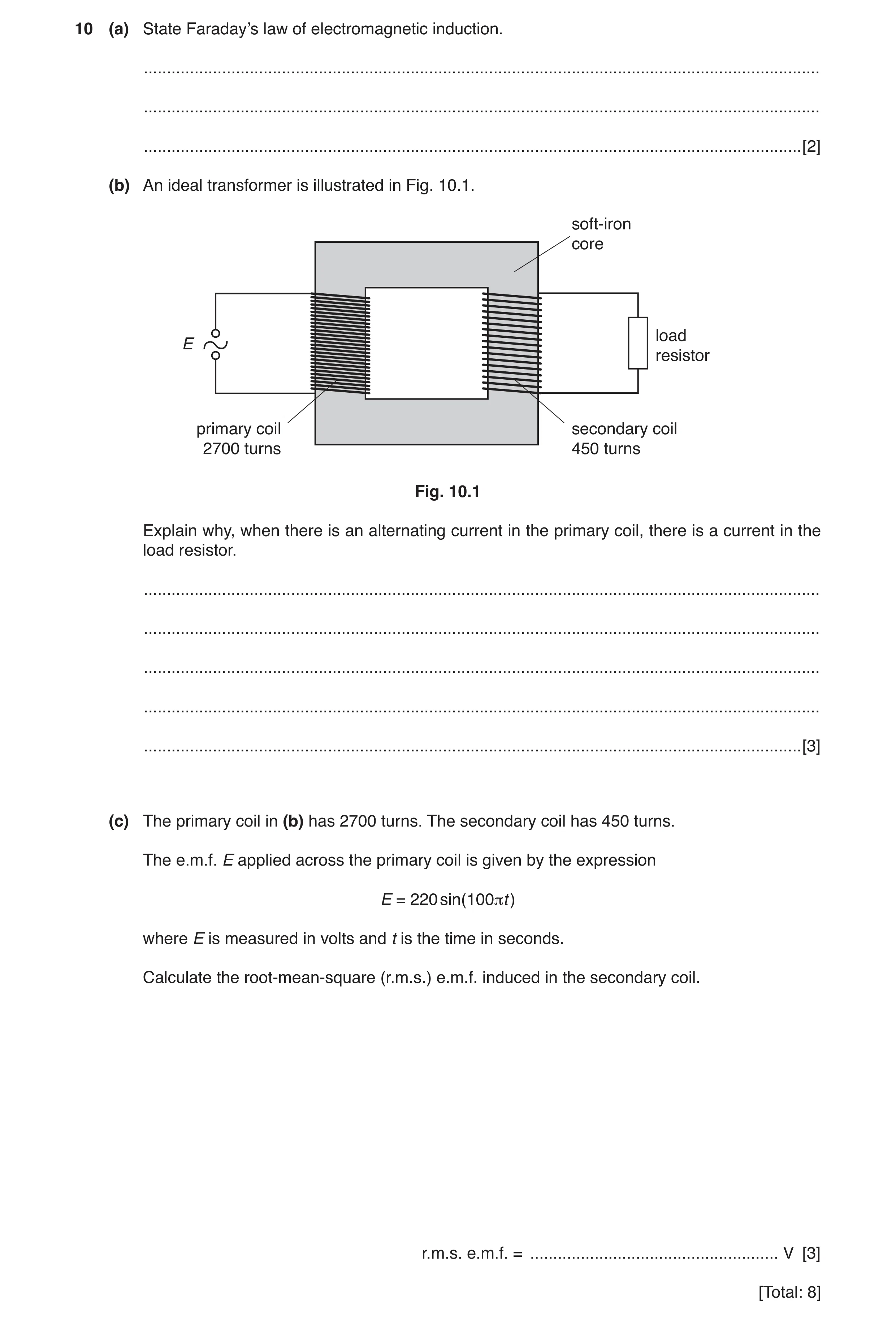
10 (a) State Faraday’s law of electromagnetic induction. … … … [2] (b) An ideal transformer is illustrated in Fig. 10.1. soft-iron core load E resistor primary coil secondary coil 2700 turns 450 turns Fig. 10.1 Explain why, when there is an alternating current in the primary coil, there is a current in the load resistor. … … … … … [3] (c) The primary coil in (b) has 2700 turns. The secondary coil has 450 turns. The e.m.f. E applied across the primary coil is given by the expression E = 220 sin(100πt ) where E is measured in volts and t is the time in seconds. Calculate the root-mean-square (r.m.s.) e.m.f. induced in the secondary coil. r.m.s. e.m.f. = … V [3] [Total: 8]
8 marks
Mark scheme: 10(a) (induced) e.m.f. proportional to rate M1 of change of (magnetic) flux (linkage) A1 10(b) current in primary coil gives rise to magnetic flux B1 changing (magnetic) flux in core links with secondary coil B1 induced e.m.f. (in secondary coil) causes current in load/resistor B1 10(c) correct application of turns ratio: to peak voltage ratio, giving (V0 / 220) = (450 / 2700) or to r.m.s. voltage ratio, giving (Vr.m.s. / 156) = (450 / 2700) C1 correct application of √2 factor: to peak applied e.m.f., giving 220 / √2 or to peak output em.f., giving 37 / √2 C1 Vr.m.s. = 26 V A1
This question in 9702/42 May/June 2019
Q16 · A solenoid is connected in series with a battery and a switch, as illustrated in Fig 9702/43 May/June 2019
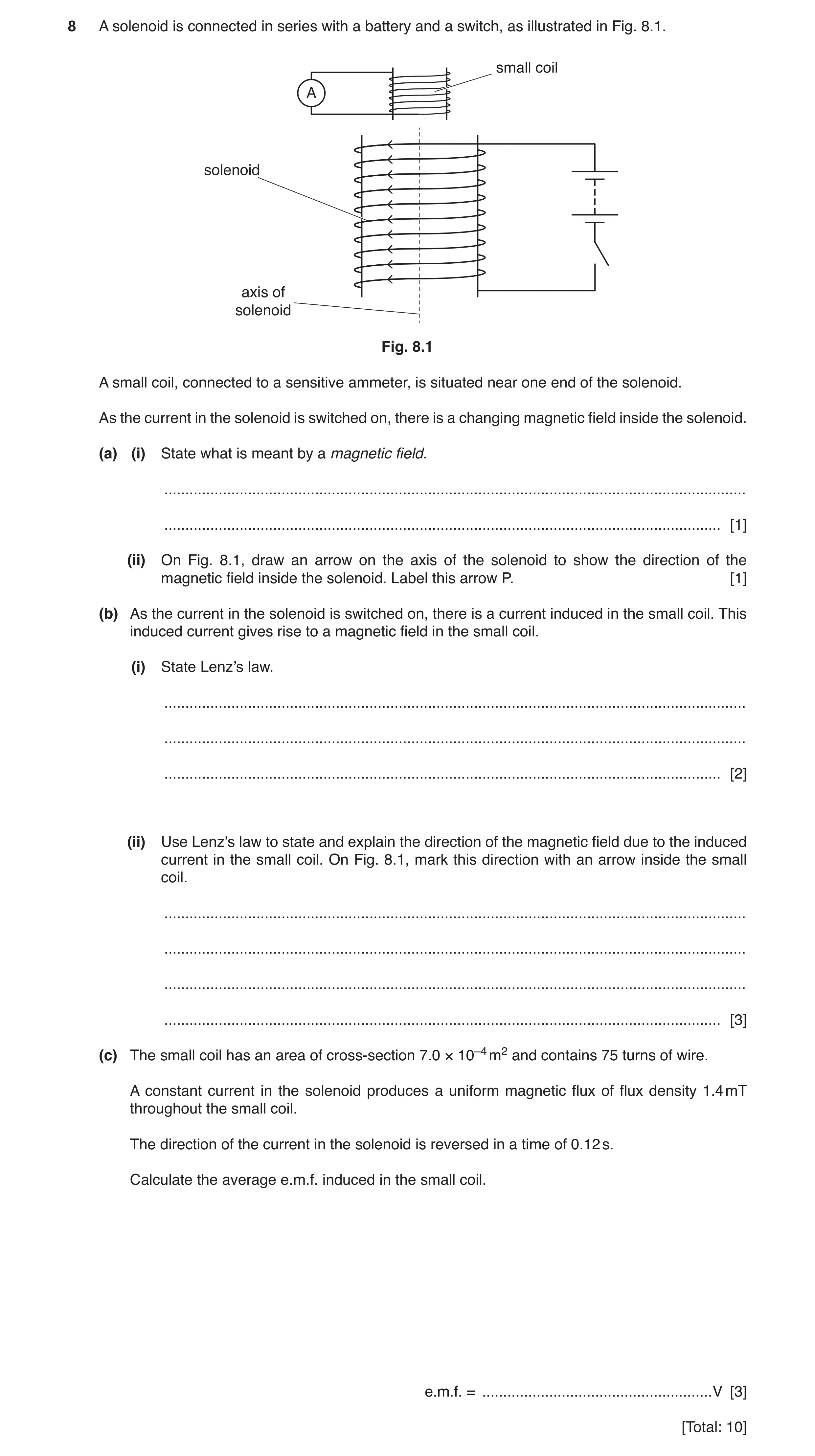
8 A solenoid is connected in series with a battery and a switch, as illustrated in Fig. 8.1. small coil A solenoid axis of solenoid Fig. 8.1 A small coil, connected to a sensitive ammeter, is situated near one end of the solenoid. As the current in the solenoid is switched on, there is a changing magnetic field inside the solenoid. (a) (i) State what is meant by a magnetic field. … … [1] (ii) On Fig. 8.1, draw an arrow on the axis of the solenoid to show the direction of the magnetic field inside the solenoid. Label this arrow P. [1] (b) As the current in the solenoid is switched on, there is a current induced in the small coil. This induced current gives rise to a magnetic field in the small coil. (i) State Lenz’s law. … … … [2] (ii) Use Lenz’s law to state and explain the direction of the magnetic field due to the induced current in the small coil. On Fig. 8.1, mark this direction with an arrow inside the small coil. … … … … [3] (c) The small coil has an area of cross-section 7.0 × 10⁻⁴ m2 and contains 75 turns of wire. A constant current in the solenoid produces a uniform magnetic flux of flux density 1.4 mT throughout the small coil. The direction of the current in the solenoid is reversed in a time of 0.12 s. Calculate the average e.m.f. induced in the small coil. e.m.f. = … V [3] [Total: 10]
10 marks
Mark scheme: 8(a)(i) region where a force is exerted on: a magnetic pole or a moving charge or a current-carrying wire B1 8(a)(ii) arrow on axis of solenoid pointing downwards labelled P B1 8(b)(i) direction of induced e.m.f./current M1 (tends to) oppose the change causing it A1 8(b)(ii) magnetic field in solenoid is increasing B1 field in coil in opposite direction to oppose increase B1 arrow inside or just above small coil pointing in opposite direction to P B1 8(c) e.m.f. = N∆φ / ∆t C1 = (75 × 1.4 × 10–3 × 2 × 7.0 × 10–4) / 0.12 C1 = 1.2 × 10⁻³ V A1
This question in 9702/43 May/June 2019
Q17 · State Faraday’s law of electromagnetic induction 9702/42 Oct/Nov 2019
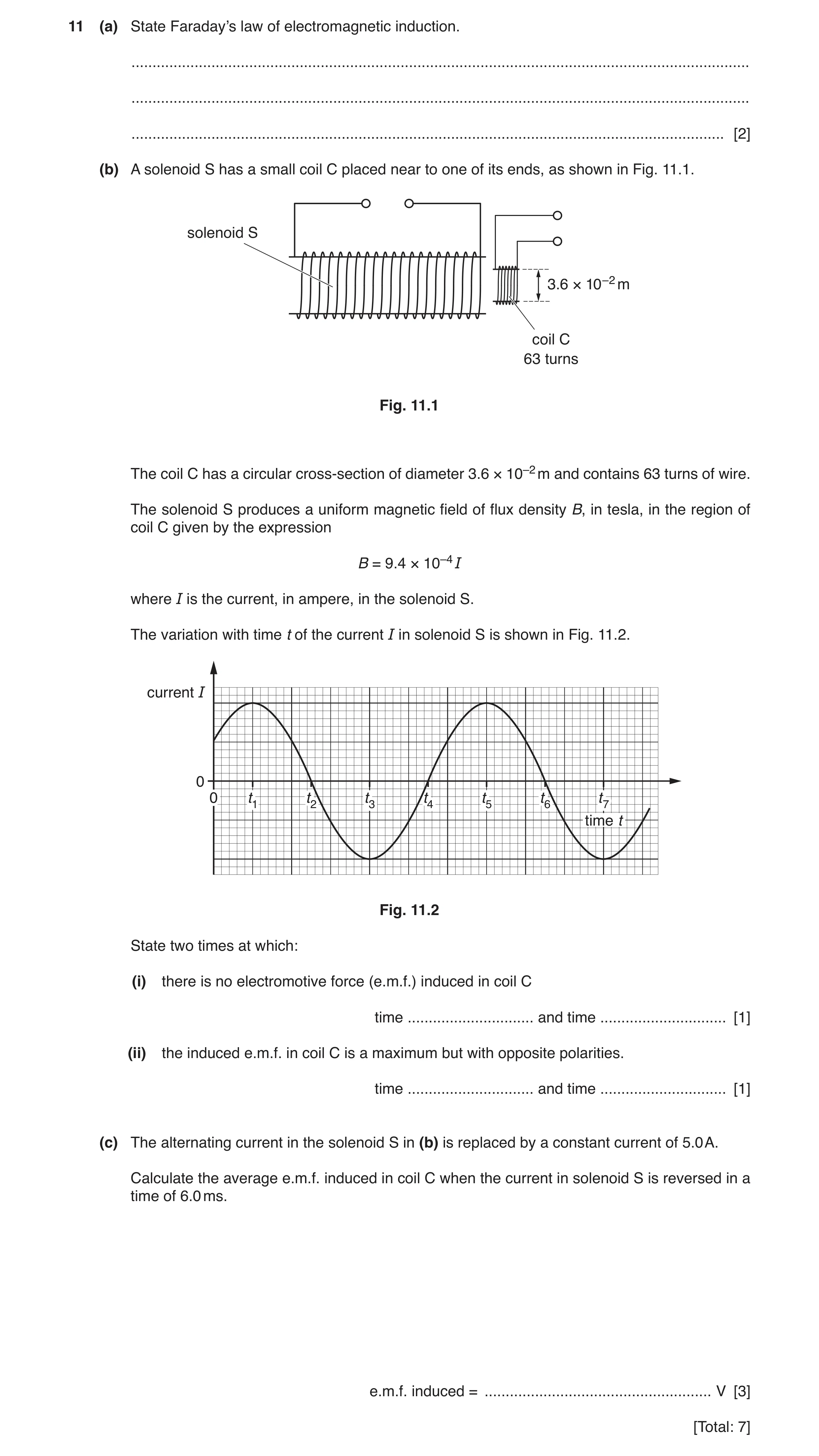
11 (a) State Faraday’s law of electromagnetic induction. … … … [2] (b) A solenoid S has a small coil C placed near to one of its ends, as shown in Fig. 11.1. solenoid S 3.6 × 10⁻² m coil C 63 turns Fig. 11.1 The coil C has a circular cross-section of diameter 3.6 × 10⁻² m and contains 63 turns of wire. The solenoid S produces a uniform magnetic field of flux density B, in tesla, in the region of coil C given by the expression B = 9.4 × 10⁻⁴ I where I is the current, in ampere, in the solenoid S. The variation with time t of the current I in solenoid S is shown in Fig. 11.2. current I 0 0 t1 t2 t3 t4 t5 t6 t7 time t Fig. 11.2 State two times at which: (i) there is no electromotive force (e.m.f.) induced in coil C time … and time … [1] (ii) the induced e.m.f. in coil C is a maximum but with opposite polarities. time … and time … [1] (c) The alternating current in the solenoid S in (b) is replaced by a constant current of 5.0 A. Calculate the average e.m.f. induced in coil C when the current in solenoid S is reversed in a time of 6.0 ms. e.m.f. induced = … V [3] [Total: 7]
7 marks
Mark scheme: 11(a) (induced) e.m.f. proportional to rate M1 of change of (magnetic) flux (linkage) A1 11(b)(i) any two from t1, t3, t5, t7 A1 11(b)(ii) t2 and t4 or t4 and t6 A1 11(c) e.m.f. = N∆Φ / ∆t C1 = (2 × 9.4 × 10–4 × 5.0 × π × (1.8 × 10⁻²)2 × 63) / (6.0 × 10⁻³) C1 = 0.10 V A1
This question in 9702/42 Oct/Nov 2019
Q18 · A coil of wire is situated in a uniform magnetic field of flux density B 9702/41 May/June 2020
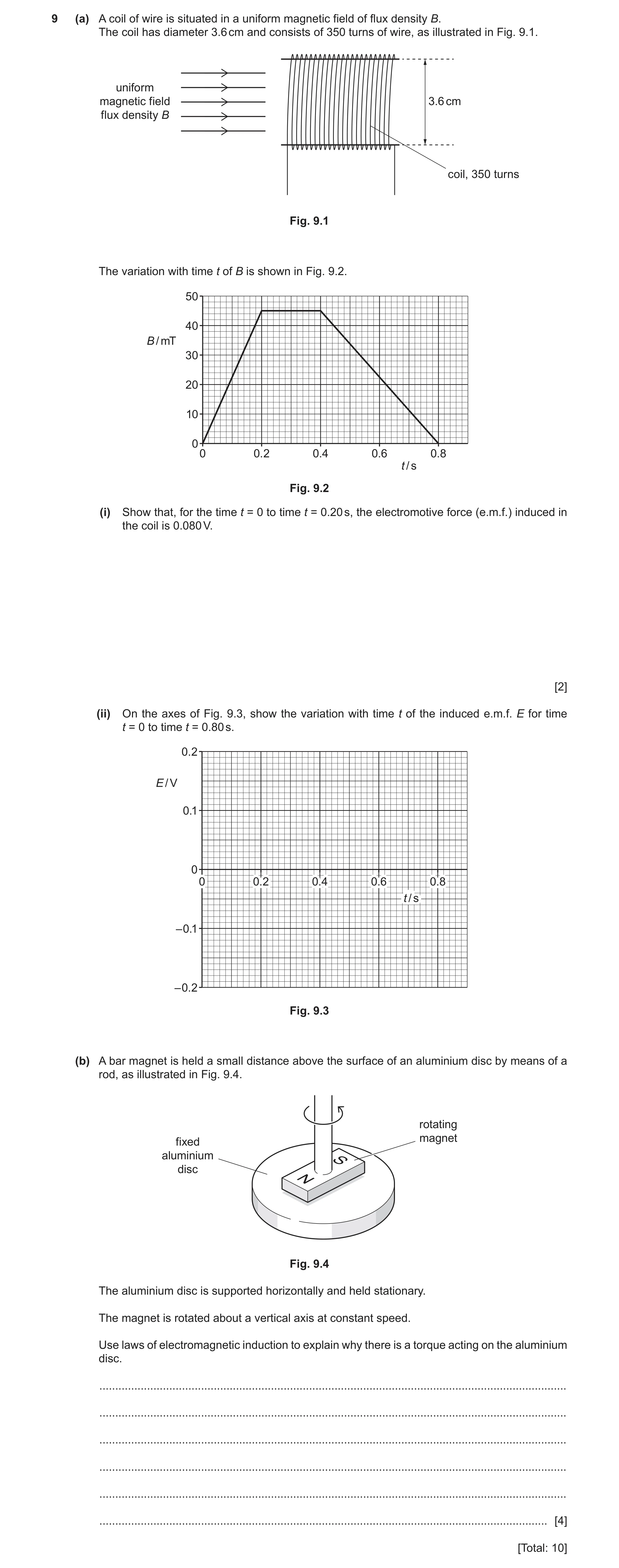
9 (a) A coil of wire is situated in a uniform magnetic field of flux density B. The coil has diameter 3.6 cm and consists of 350 turns of wire, as illustrated in Fig. 9.1. uniform magnetic field 3.6 cm flux density B coil, 350 turns Fig. 9.1 The variation with time t of B is shown in Fig. 9.2. 50 40 B / mT 30 20 10 0 0 0.2 0.4 0.6 0.8 t / s Fig. 9.2 (i) Show that, for the time t = 0 to time t = 0.20 s, the electromotive force (e.m.f.) induced in the coil is 0.080 V. [2] (ii) On the axes of Fig. 9.3, show the variation with time t of the induced e.m.f. E for time t = 0 to time t = 0.80 s. 0.2 E / V 0.1 0 0 0.2 0.4 0.6 0.8 t / s –0.1 –0.2 Fig. 9.3 (b) A bar magnet is held a small distance above the surface of an aluminium disc by means of a rod, as illustrated in Fig. 9.4. rotating magnet fixed aluminium disc Fig. 9.4 The aluminium disc is supported horizontally and held stationary. The magnet is rotated about a vertical axis at constant speed. Use laws of electromagnetic induction to explain why there is a torque acting on the aluminium disc. … … … … … … [4] [Total: 10]
10 marks
Mark scheme: 9(a)(i) e.m.f. = (Δ)B × AN / t C1 = 45 × 10–3 × π × (1.8 × 10⁻²)2 × 350 / 0.20 = 0.080 V A1 9(a)(ii) 0 to 0.2 s: straight horizontal line at 0.080 V or –0.080 V B1 0.2 s to 0.4 s: zero B1 0.4 s to 0.8 s: straight horizontal line at 0.040 V or –0.040 V B1 opposite polarity to 0 to 0.2 s line B1 9(b) either disc cuts flux lines (of the magnet) or there is a changing flux in the disc B1 (by Faraday’s law) e.m.f. is induced in the disc B1 e.m.f. causes (eddy) currents in the disc B1 current in the magnetic field (of the magnet) causes force on disc B1
This question in 9702/41 May/June 2020
Q19 · State Faraday’s law of electromagnetic induction 9702/42 May/June 2020
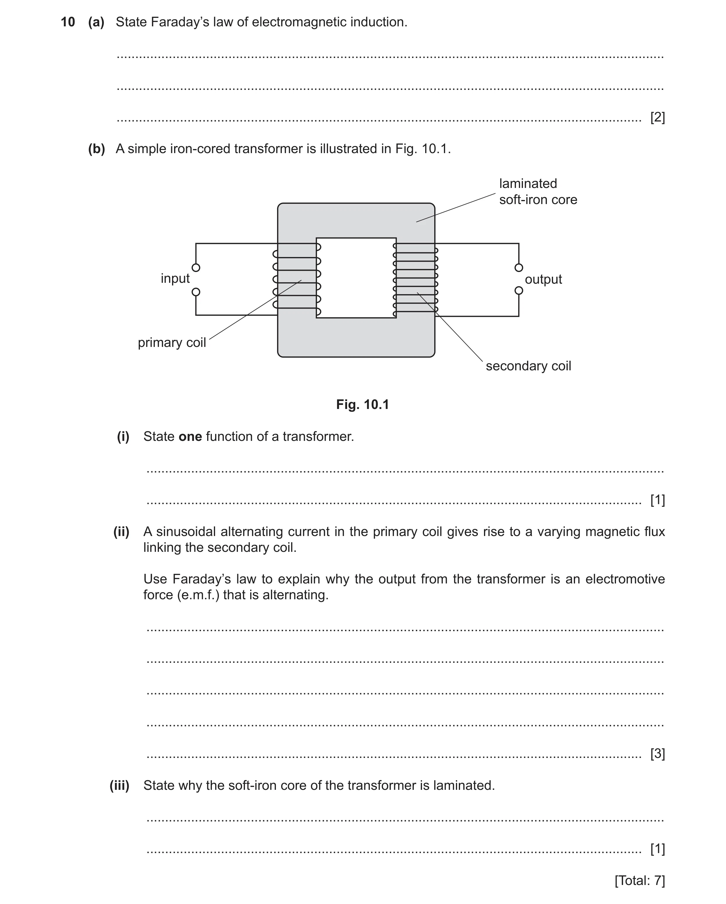
10 (a) State Faraday’s law of electromagnetic induction. … … … [2] (b) A simple iron‑cored transformer is illustrated in Fig. 10.1. laminated soft-iron core input output primary coil secondary coil Fig. 10.1 (i) State one function of a transformer. … … [1] (ii) A sinusoidal alternating current in the primary coil gives rise to a varying magnetic flux linking the secondary coil. Use Faraday’s law to explain why the output from the transformer is an electromotive force (e.m.f.) that is alternating. … … … … … [3] (iii) State why the soft‑iron core of the transformer is laminated. … … [1] [Total: 7]
7 marks
Mark scheme: 10(a) (induced) electromotive force is proportional to rate M1 of change of (magnetic) flux (linkage) A1 10(b)(i) to change magnitude of potential difference B1 10(b)(ii) magnitude of e.m.f. varies as rate of change of flux changes B1 direction of e.m.f. changes when direction of change of flux reverses/when flux changes from increasing to decreasing B1 flux is continuously increasing and decreasing, so polarity of e.m.f. is continuously switching B1 10(b)(iii) to reduce energy/power losses or to reduce eddy currents B1
This question in 9702/42 May/June 2020
Q20 · A coil of wire is situated in a uniform magnetic field of flux density B 9702/43 May/June 2020
9 (a) A coil of wire is situated in a uniform magnetic field of flux density B. The coil has diameter 3.6 cm and consists of 350 turns of wire, as illustrated in Fig. 9.1. uniform magnetic field 3.6 cm flux density B coil, 350 turns Fig. 9.1 The variation with time t of B is shown in Fig. 9.2. 50 40 B / mT 30 20 10 0 0 0.2 0.4 0.6 0.8 t / s Fig. 9.2 (i) Show that, for the time t = 0 to time t = 0.20 s, the electromotive force (e.m.f.) induced in the coil is 0.080 V. [2] (ii) On the axes of Fig. 9.3, show the variation with time t of the induced e.m.f. E for time t = 0 to time t = 0.80 s. 0.2 E / V 0.1 0 0 0.2 0.4 0.6 0.8 t / s –0.1 –0.2 Fig. 9.3 (b) A bar magnet is held a small distance above the surface of an aluminium disc by means of a rod, as illustrated in Fig. 9.4. rotating magnet fixed aluminium disc Fig. 9.4 The aluminium disc is supported horizontally and held stationary. The magnet is rotated about a vertical axis at constant speed. Use laws of electromagnetic induction to explain why there is a torque acting on the aluminium disc. … … … … … … [4] [Total: 10]
10 marks
Mark scheme: 9(a)(i) e.m.f. = (Δ)B × AN / t C1 = 45 × 10–3 × π × (1.8 × 10⁻²)2 × 350 / 0.20 = 0.080 V A1 9(a)(ii) 0 to 0.2 s: straight horizontal line at 0.080 V or –0.080 V B1 0.2 s to 0.4 s: zero B1 0.4 s to 0.8 s: straight horizontal line at 0.040 V or –0.040 V B1 opposite polarity to 0 to 0.2 s line B1 9(b) either disc cuts flux lines (of the magnet) or there is a changing flux in the disc B1 (by Faraday’s law) e.m.f. is induced in the disc B1 e.m.f. causes (eddy) currents in the disc B1 current in the magnetic field (of the magnet) causes force on disc B1
This question in 9702/43 May/June 2020
Question 21 9702/41 Oct/Nov 2020
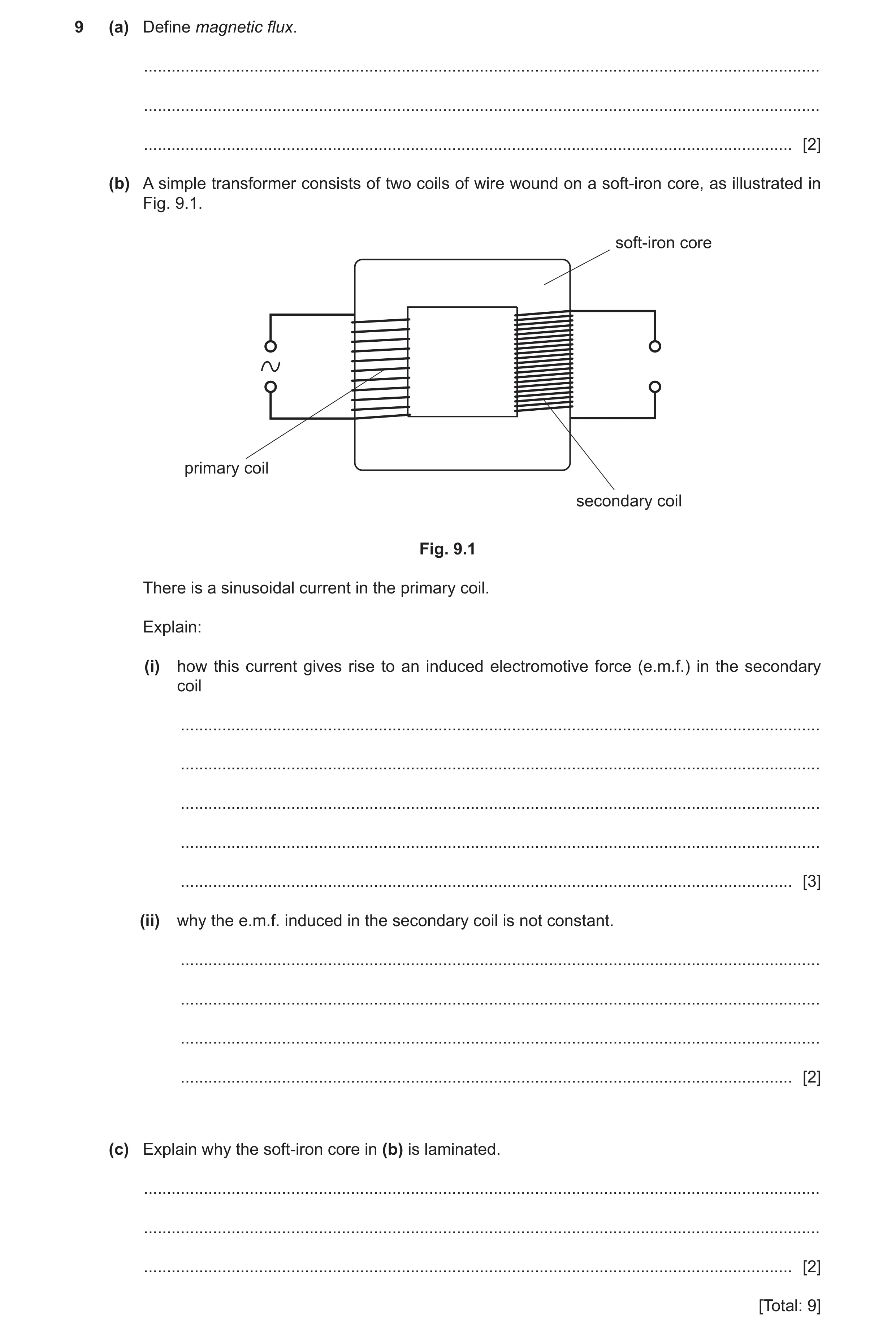
9 (a) Define magnetic flux. … … … [2] (b) A simple transformer consists of two coils of wire wound on a soft-iron core, as illustrated in Fig. 9.1. soft-iron core primary coil secondary coil Fig. 9.1 There is a sinusoidal current in the primary coil. Explain: (i) how this current gives rise to an induced electromotive force (e.m.f.) in the secondary coil … … … … … [3] (ii) why the e.m.f. induced in the secondary coil is not constant. … … … … [2] (c) Explain why the soft-iron core in (b) is laminated. … … … [2] [Total: 9]
9 marks
Mark scheme: 9(a) flux density × area M1 where flux is normal to area A1 or flux density × area × sin θ (M1) where θ is angle between flux direction and (plane of) area (A1) 9(b)(i) (alternating) current creates changing (magnetic) flux B1 core links (magnetic) flux with secondary coil B1 changing flux (in secondary) causes induced e.m.f. B1 9(b)(ii) rate of change of flux is not constant B1 (induced) e.m.f. is proportional to rate of change of flux B1 9(c) reduces induced currents in core B1 hence reduces energy losses (in core) B1
This question in 9702/41 Oct/Nov 2020
Q22 · A small coil is placed close to one end of a solenoid connected to a power supply 9702/42 Oct/Nov 2020
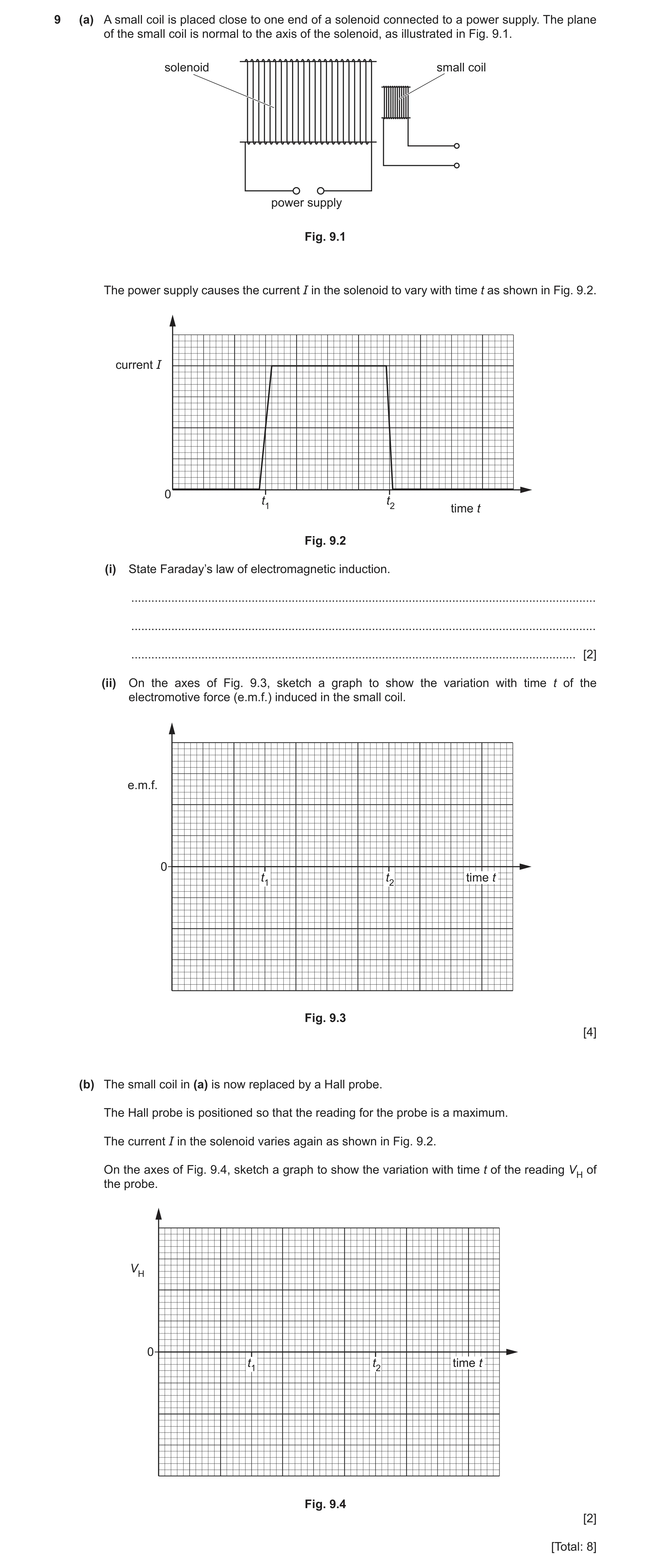
9 (a) A small coil is placed close to one end of a solenoid connected to a power supply. The plane of the small coil is normal to the axis of the solenoid, as illustrated in Fig. 9.1. solenoid small coil power supply Fig. 9.1 The power supply causes the current I in the solenoid to vary with time t as shown in Fig. 9.2. current I 0 t1 t2 time t Fig. 9.2 (i) State Faraday’s law of electromagnetic induction. … … … [2] (ii) On the axes of Fig. 9.3, sketch a graph to show the variation with time t of the electromotive force (e.m.f.) induced in the small coil. e.m.f. 0 t1 t2 time t Fig. 9.3 [4] (b) The small coil in (a) is now replaced by a Hall probe. The Hall probe is positioned so that the reading for the probe is a maximum. The current I in the solenoid varies again as shown in Fig. 9.2. On the axes of Fig. 9.4, sketch a graph to show the variation with time t of the reading VH of the probe. VH 0 t1 t2 time t Fig. 9.4 [2] [Total: 8]
8 marks
Mark scheme: 9(a)(i) (induced) e.m.f. (directly) proportional to rate M1 of change of magnetic flux (linkage) A1 9(a)(ii) e.m.f. = 0 apart from thin pulses at t1 and t2 B1 rectangular pulses centred on t1 and t2, of widths 2 small squares and 1 small square respectively B1 e.m.fs. at t1 and t2 have opposite polarities B1 magnitude of e.m.f. at t2 double the magnitude of e.m.f. at t1 B1 9(b) VH shown as zero before (t1 – 2 squares) and after (t2 + 2 squares) and rises to a constant non-zero value between t1 and t2 M1 change at t1 shown as 2 small squares wide and change at t2 shown as 1 small square wide A1
This question in 9702/42 Oct/Nov 2020
Question 23 9702/43 Oct/Nov 2020
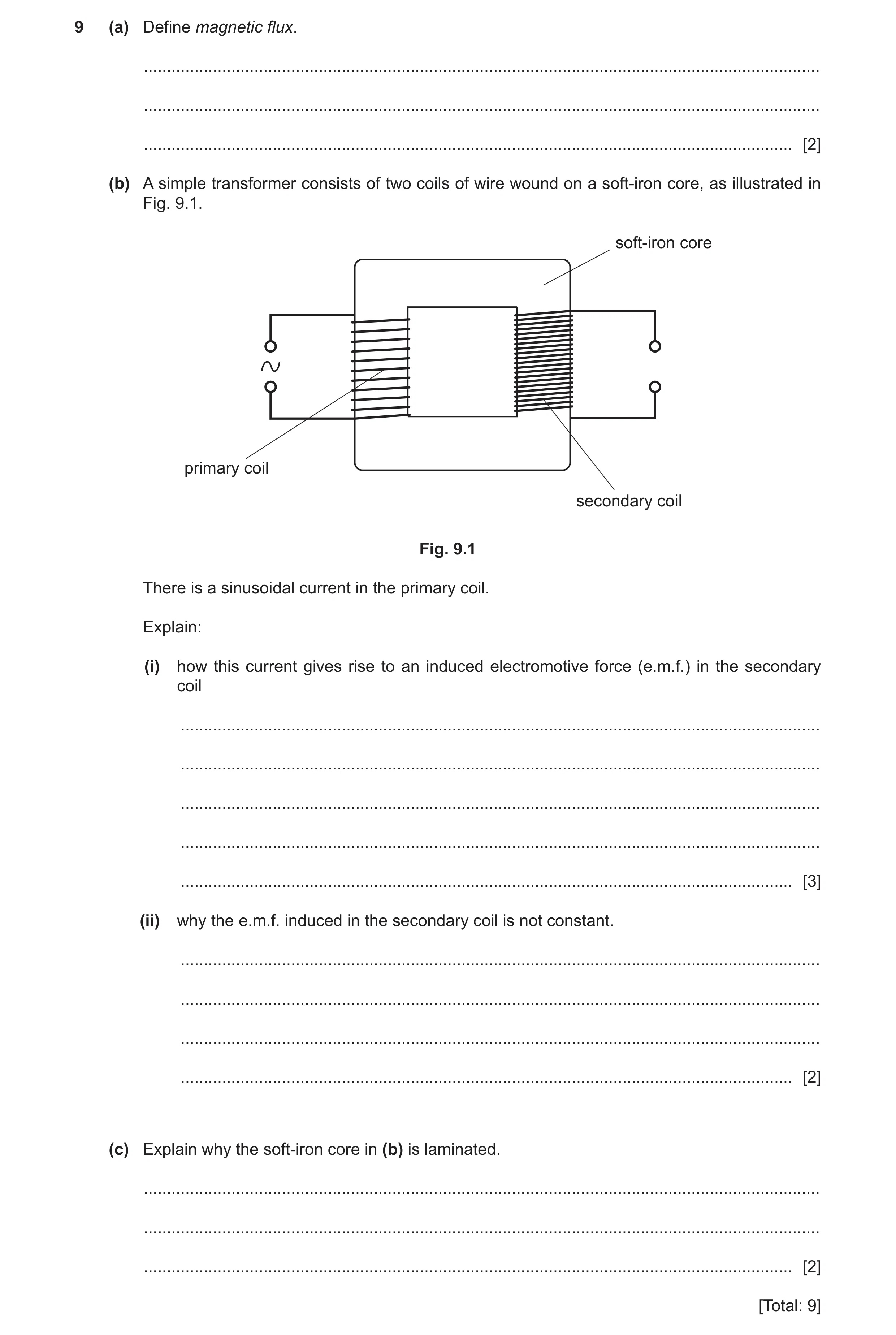
9 (a) Define magnetic flux. … … … [2] (b) A simple transformer consists of two coils of wire wound on a soft-iron core, as illustrated in Fig. 9.1. soft-iron core primary coil secondary coil Fig. 9.1 There is a sinusoidal current in the primary coil. Explain: (i) how this current gives rise to an induced electromotive force (e.m.f.) in the secondary coil … … … … … [3] (ii) why the e.m.f. induced in the secondary coil is not constant. … … … … [2] (c) Explain why the soft-iron core in (b) is laminated. … … … [2] [Total: 9]
9 marks
Mark scheme: 9(a) flux density × area M1 where flux is normal to area A1 or flux density × area × sin θ (M1) where θ is angle between flux direction and (plane of) area (A1) 9(b)(i) (alternating) current creates changing (magnetic) flux B1 core links (magnetic) flux with secondary coil B1 changing flux (in secondary) causes induced e.m.f. B1 9(b)(ii) rate of change of flux is not constant B1 (induced) e.m.f. is proportional to rate of change of flux B1 9(c) reduces induced currents in core B1 hence reduces energy losses (in core) B1
This question in 9702/43 Oct/Nov 2020
Q24 · Define magnetic flux linkage 9702/42 Feb/March 2021
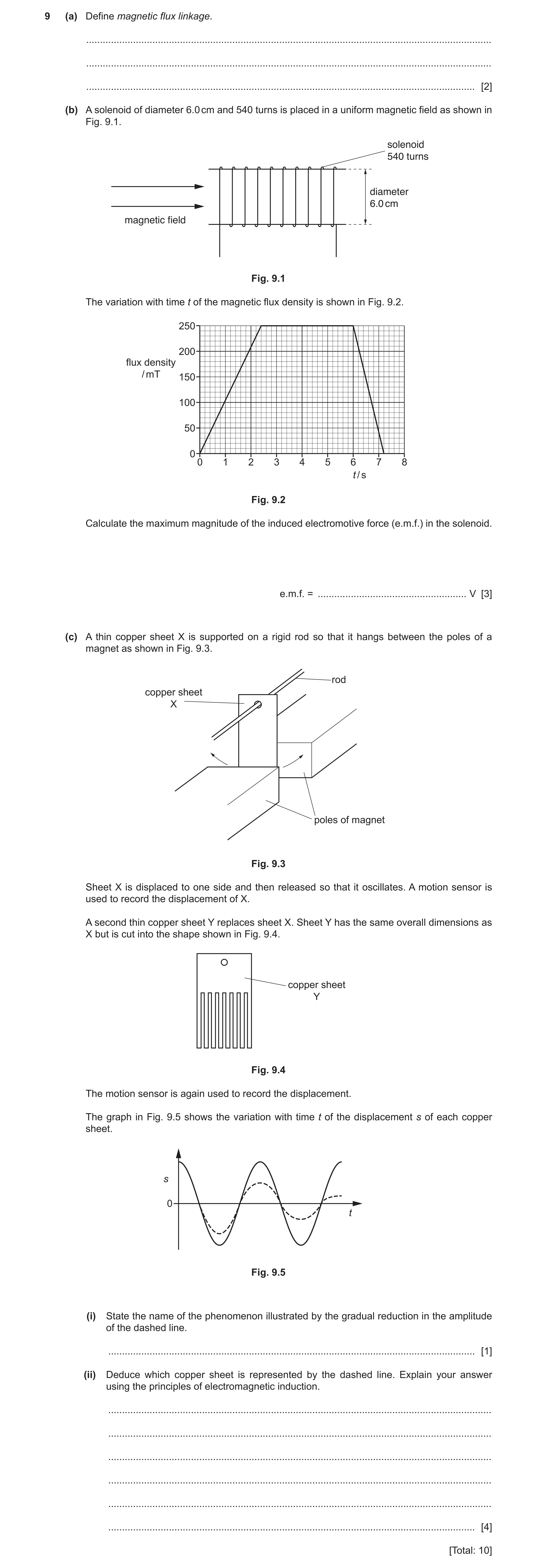
9 (a) Define magnetic flux linkage. … … … [2] (b) A solenoid of diameter 6.0 cm and 540 turns is placed in a uniform magnetic field as shown in Fig. 9.1. solenoid 540 turns diameter 6.0 cm magnetic field Fig. 9.1 The variation with time t of the magnetic flux density is shown in Fig. 9.2. 250 200 flux density / mT 150 100 50 0 0 1 2 3 4 5 6 7 8 t / s Fig. 9.2 Calculate the maximum magnitude of the induced electromotive force (e.m.f.) in the solenoid. e.m.f. = … V [3] (c) A thin copper sheet X is supported on a rigid rod so that it hangs between the poles of a magnet as shown in Fig. 9.3. rod copper sheet X poles of magnet Fig. 9.3 Sheet X is displaced to one side and then released so that it oscillates. A motion sensor is used to record the displacement of X. A second thin copper sheet Y replaces sheet X. Sheet Y has the same overall dimensions as X but is cut into the shape shown in Fig. 9.4. copper sheet Y Fig. 9.4 The motion sensor is again used to record the displacement. The graph in Fig. 9.5 shows the variation with time t of the displacement s of each copper sheet. s 0 t Fig. 9.5 (i) State the name of the phenomenon illustrated by the gradual reduction in the amplitude of the dashed line. … [1] (ii) Deduce which copper sheet is represented by the dashed line. Explain your answer using the principles of electromagnetic induction. … … … … … … [4] [Total: 10]
10 marks
Mark scheme: 9(a) (magnetic) flux density × area × number of turns M1 area is perpendicular to (magnetic) field A1 9(b) use of t = 1.2 s C1 BAN t ε Δ = Δ 2 0.250 0.030 540 1.2 π × × × = C1 0.32 V = A1 9(c)(i) light damping B1 Question Answer Marks 9(c)(ii) sheet cuts (magnetic) flux and causes induced emf B1 (induced) emf causes (eddy) currents (in sheet) B1 either currents (in sheet) cause resistive force or currents (in sheet) dissipate energy B1 smaller currents in Y or larger currents in X, so dashed line is X B1
This question in 9702/42 Feb/March 2021
Question 25 9702/41 May/June 2021
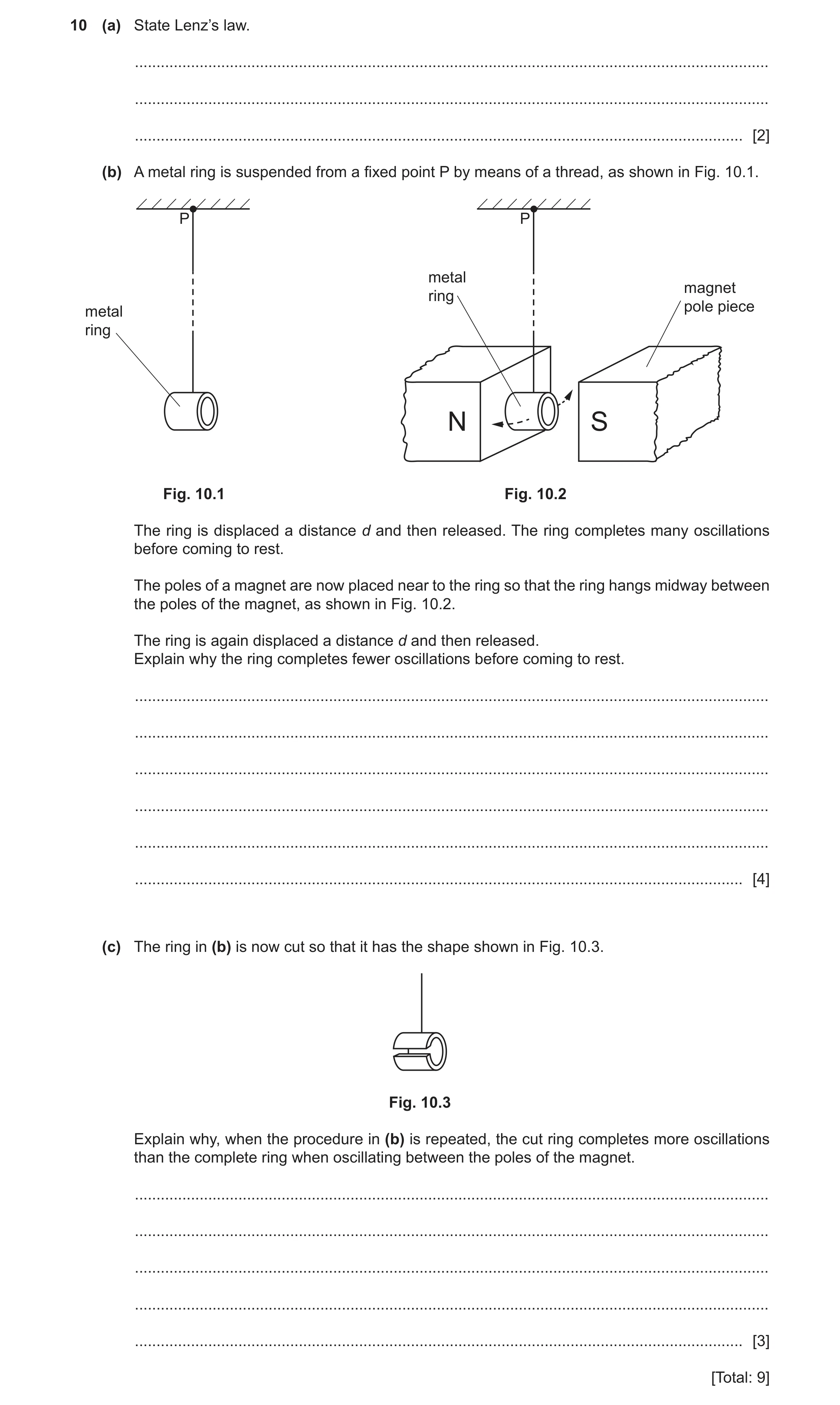
10 (a) State Lenz’s law. … … … [2] (b) A metal ring is suspended from a fixed point P by means of a thread, as shown in Fig. 10.1. P P metal magnet ring pole piece metal ring N S Fig. 10.1 Fig. 10.2 The ring is displaced a distance d and then released. The ring completes many oscillations before coming to rest. The poles of a magnet are now placed near to the ring so that the ring hangs midway between the poles of the magnet, as shown in Fig. 10.2. The ring is again displaced a distance d and then released. Explain why the ring completes fewer oscillations before coming to rest. … … … … … … [4] (c) The ring in (b) is now cut so that it has the shape shown in Fig. 10.3. Fig. 10.3 Explain why, when the procedure in (b) is repeated, the cut ring completes more oscillations than the complete ring when oscillating between the poles of the magnet. … … … … … [3] [Total: 9]
9 marks
Mark scheme: 10(a) direction of (induced) e.m.f. M1 is such as to oppose the change causing it A1 10(b) ring cuts (magnetic) flux and causes induced e.m.f. in ring B1 (induced) e.m.f. causes (eddy/induced) currents (in ring) B1 currents (in ring) cause magnetic field (around ring) M1 two fields interact to cause resistive/opposing force A1 or current (in ring) is in a magnetic field (M1) which causes resistive force (A1) or currents (in ring) dissipate thermal energy (M1) (thermal) energy comes from energy of oscillations (A1) 10(c) current cannot pass all the way around the ring B1 (induced) currents smaller B1 smaller resistive force (so more oscillations) or smaller rate of dissipation of energy (so more oscillations) B1
This question in 9702/41 May/June 2021
Q26 · State two situations in which a charged particle in a magnetic field does not experience… 9702/42 May/June 2021
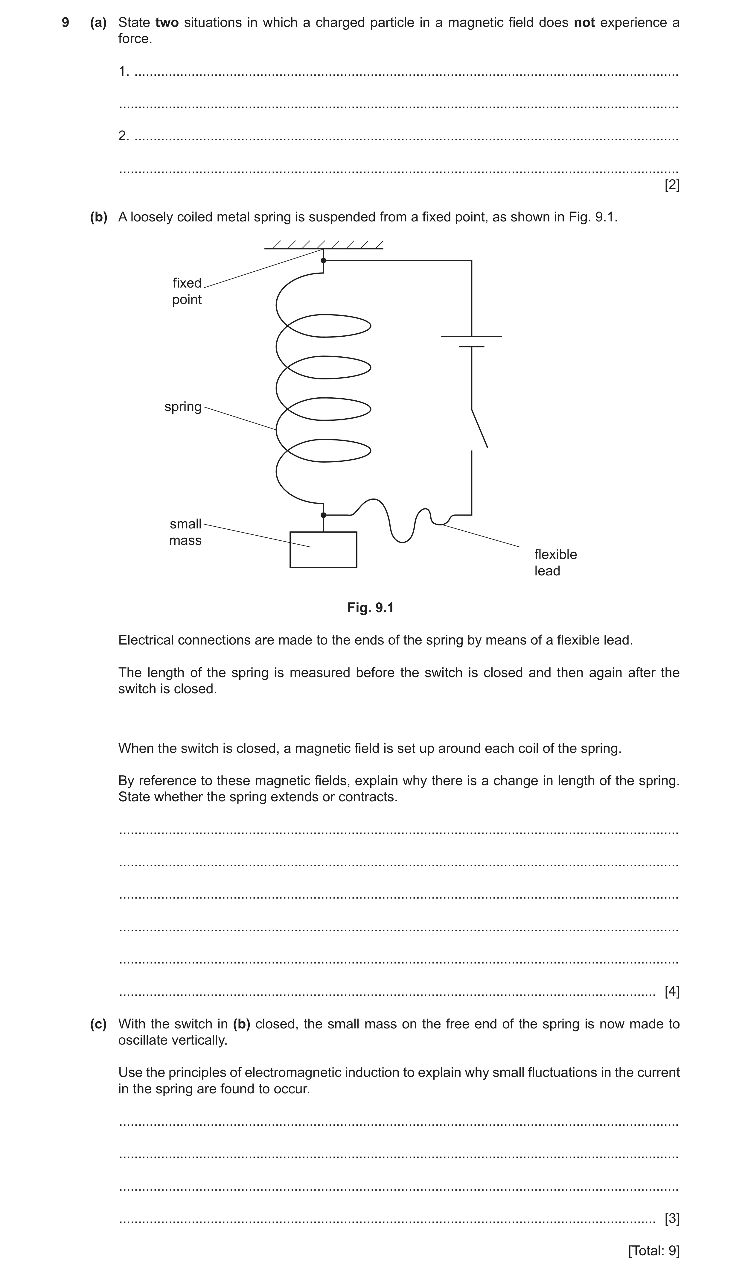
9 (a) State two situations in which a charged particle in a magnetic field does not experience a force. 1. … … 2. … … [2] (b) A loosely coiled metal spring is suspended from a fixed point, as shown in Fig. 9.1. fixed point spring small mass flexible lead Fig. 9.1 Electrical connections are made to the ends of the spring by means of a flexible lead. The length of the spring is measured before the switch is closed and then again after the switch is closed. When the switch is closed, a magnetic field is set up around each coil of the spring. By reference to these magnetic fields, explain why there is a change in length of the spring. State whether the spring extends or contracts. … … … … … … [4] (c) With the switch in (b) closed, the small mass on the free end of the spring is now made to oscillate vertically. Use the principles of electromagnetic induction to explain why small fluctuations in the current in the spring are found to occur. … … … … [3] [Total: 9]
9 marks
Mark scheme: 9(a) (particle is) stationary/not moving B1 (particle is) moving parallel to the (magnetic) field B1 9(b) magnetic field around each coil is circular or each coil is normal to magnetic field due to adjacent coils B1 current in coil interacts with (magnetic) field to exert force (on coil) B1 force is normal to both coil and magnetic field or force parallel to axis (of coil) B1 forces between coils are attractive so spring contracts B1 9(c) (oscillating) coils cut magnetic flux or as separation of coils changes, magnetic flux changes B1 cutting flux causes induced e.m.f. in coils B1 changing (induced) e.m.f. causes changing current (in coil) B1
This question in 9702/42 May/June 2021
Question 27 9702/43 May/June 2021
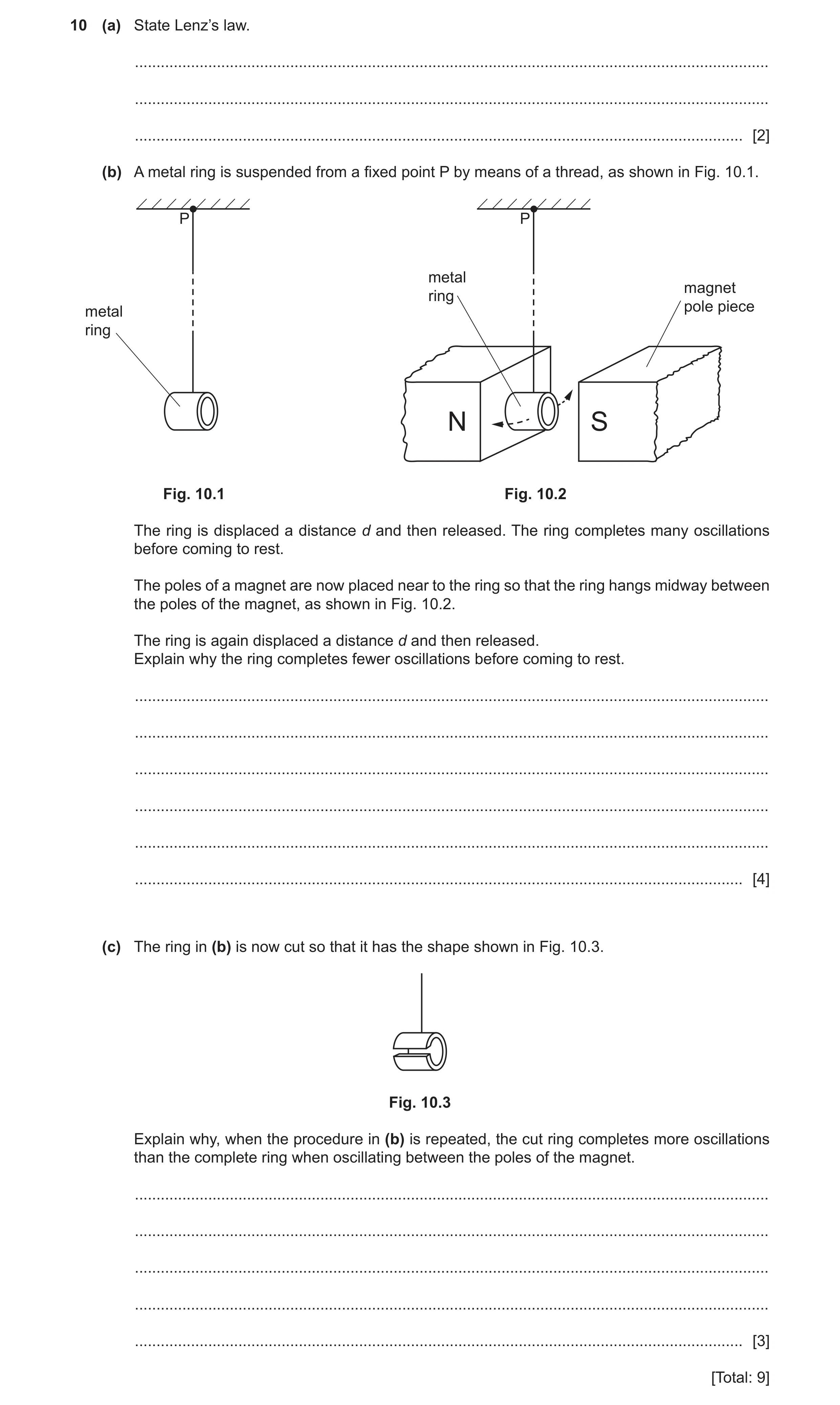
10 (a) State Lenz’s law. … … … [2] (b) A metal ring is suspended from a fixed point P by means of a thread, as shown in Fig. 10.1. P P metal magnet ring pole piece metal ring N S Fig. 10.1 Fig. 10.2 The ring is displaced a distance d and then released. The ring completes many oscillations before coming to rest. The poles of a magnet are now placed near to the ring so that the ring hangs midway between the poles of the magnet, as shown in Fig. 10.2. The ring is again displaced a distance d and then released. Explain why the ring completes fewer oscillations before coming to rest. … … … … … … [4] (c) The ring in (b) is now cut so that it has the shape shown in Fig. 10.3. Fig. 10.3 Explain why, when the procedure in (b) is repeated, the cut ring completes more oscillations than the complete ring when oscillating between the poles of the magnet. … … … … … [3] [Total: 9]
9 marks
Mark scheme: 10(a) direction of (induced) e.m.f. M1 is such as to oppose the change causing it A1 10(b) ring cuts (magnetic) flux and causes induced e.m.f. in ring B1 (induced) e.m.f. causes (eddy/induced) currents (in ring) B1 currents (in ring) cause magnetic field (around ring) M1 two fields interact to cause resistive/opposing force A1 or current (in ring) is in a magnetic field (M1) which causes resistive force (A1) or currents (in ring) dissipate thermal energy (M1) (thermal) energy comes from energy of oscillations (A1) 10(c) current cannot pass all the way around the ring B1 (induced) currents smaller B1 smaller resistive force (so more oscillations) or smaller rate of dissipation of energy (so more oscillations) B1
This question in 9702/43 May/June 2021
Q28 · State, by reference to the power dissipated in a resistor, what is meant by the… 9702/41 Oct/Nov 2021
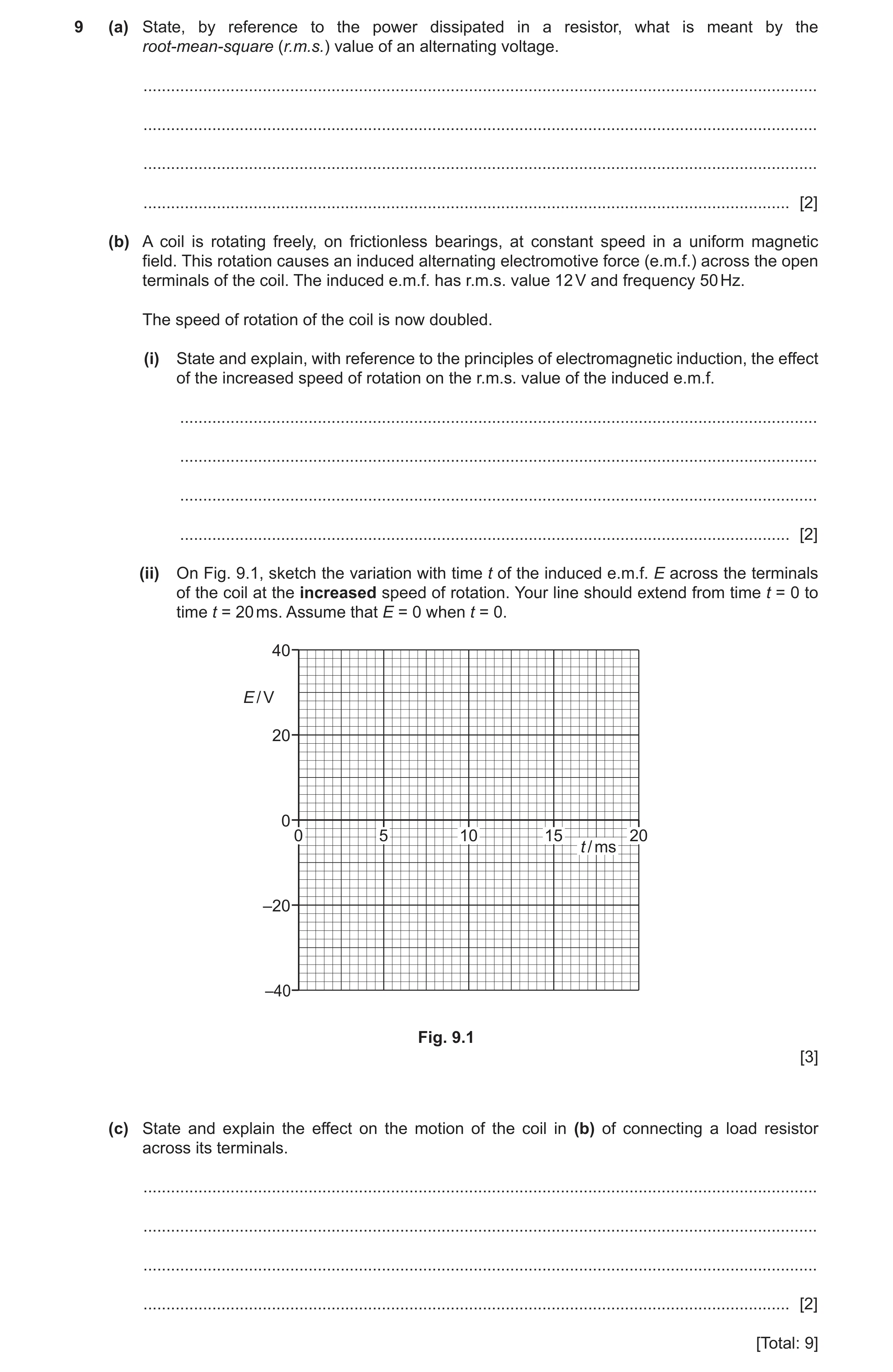
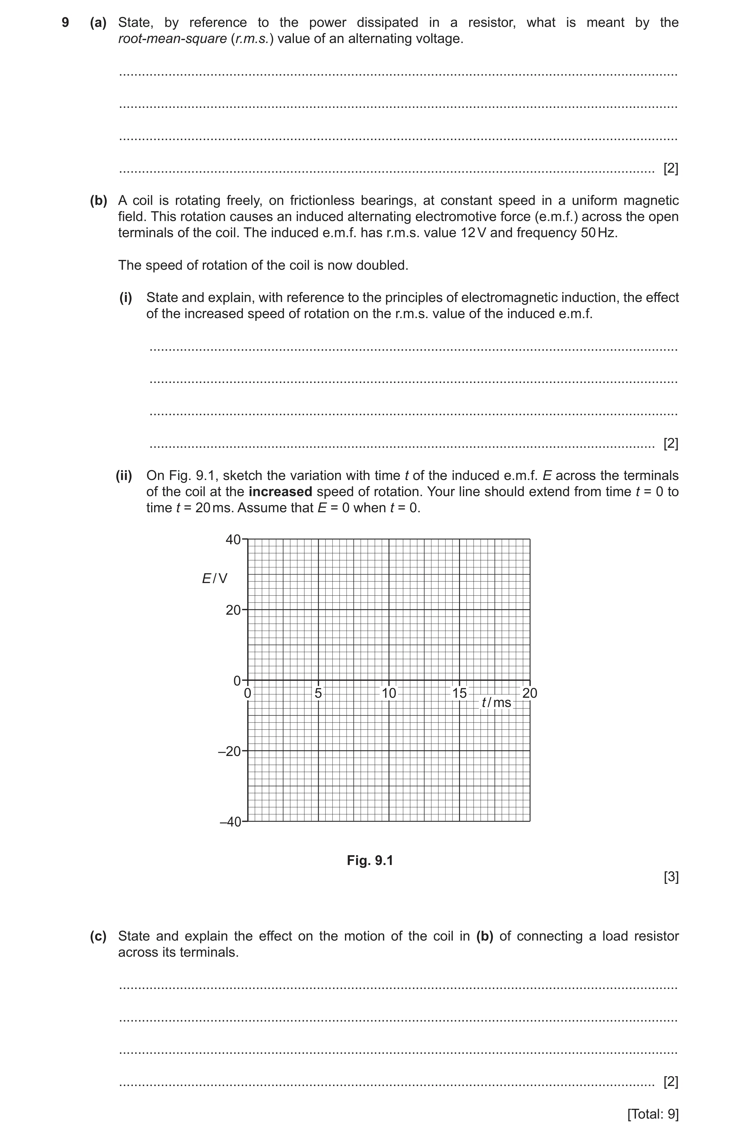
9 (a) State, by reference to the power dissipated in a resistor, what is meant by the root-mean-square (r.m.s.) value of an alternating voltage. … … … … [2] (b) A coil is rotating freely, on frictionless bearings, at constant speed in a uniform magnetic field. This rotation causes an induced alternating electromotive force (e.m.f.) across the open terminals of the coil. The induced e.m.f. has r.m.s. value 12 V and frequency 50 Hz. The speed of rotation of the coil is now doubled. (i) State and explain, with reference to the principles of electromagnetic induction, the effect of the increased speed of rotation on the r.m.s. value of the induced e.m.f. … … … … [2] (ii) On Fig. 9.1, sketch the variation with time t of the induced e.m.f. E across the terminals of the coil at the increased speed of rotation. Your line should extend from time t = 0 to time t = 20 ms. Assume that E = 0 when t = 0. 40 E / V 20 0 0 5 10 15 20 t / ms –20 –40 Fig. 9.1 [3] (c) State and explain the effect on the motion of the coil in (b) of connecting a load resistor across its terminals. … … … … [2] [Total: 9]
9 marks
Mark scheme: 9(a) constant voltage M1 that produces/dissipates same power as (the mean power of) the alternating voltage A1 9(b)(i) (maximum) rate of cutting of (magnetic) flux doubles B1 (peak and hence) r.m.s. induced e.m.f. doubles B1 9(b)(ii) sketch: (sinusoidal) wave of period 10 ms B1 peak E shown as ± 34 V (1 mark out of 2 awarded if peak E shown as ± 17 V or ± 24 V) B2 9(c) current in the coil results in forces that oppose its rotation or current in the resistor dissipates the energy of rotation B1 coil stops rotating B1
This question in 9702/41 Oct/Nov 2021
Q29 · A simple laminated iron-cored transformer consisting of a primary coil of 25 000 turns… 9702/42 Oct/Nov 2021
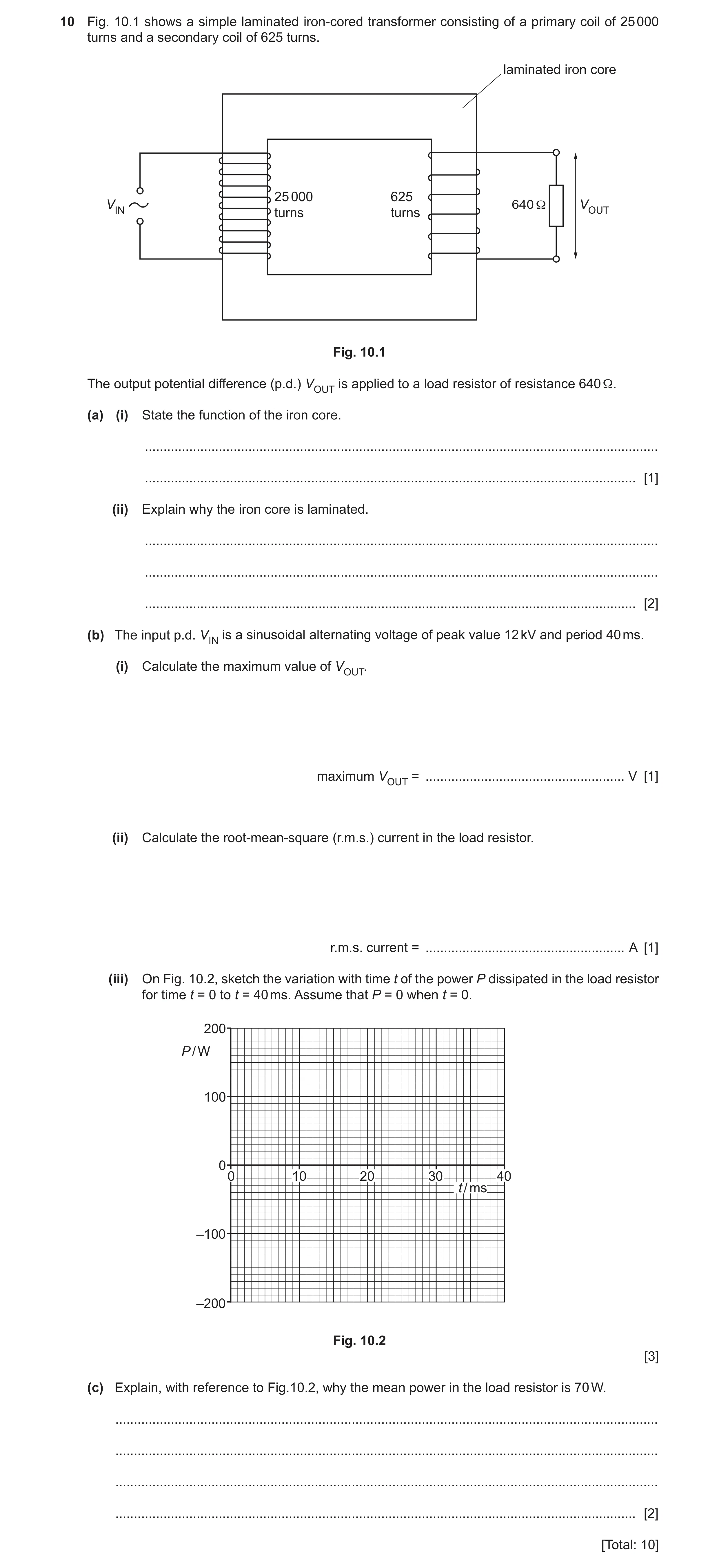
10 Fig. 10.1 shows a simple laminated iron-cored transformer consisting of a primary coil of 25 000 turns and a secondary coil of 625 turns. laminated iron core 25 000 625 VIN 640 Ω VOUT turns turns Fig. 10.1 The output potential difference (p.d.) VOUT is applied to a load resistor of resistance 640 Ω. (a) (i) State the function of the iron core. … … [1] (ii) Explain why the iron core is laminated. … … … [2] (b) The input p.d. VIN is a sinusoidal alternating voltage of peak value 12 kV and period 40 ms. (i) Calculate the maximum value of VOUT. maximum VOUT = … V [1] (ii) Calculate the root-mean-square (r.m.s.) current in the load resistor. r.m.s. current = … A [1] (iii) On Fig. 10.2, sketch the variation with time t of the power P dissipated in the load resistor for time t = 0 to t = 40 ms. Assume that P = 0 when t = 0. 200 P / W 100 0 0 10 20 30 40 t / ms –100 –200 Fig. 10.2 [3] (c) Explain, with reference to Fig.10.2, why the mean power in the load resistor is 70 W. … … … … [2] [Total: 10]
10 marks
Mark scheme: 10(a)(i) to increase the magnetic flux linkage (between the coils) B1 10(a)(ii) to reduce energy losses B1 by reducing induced currents B1 10(b)(i) maximum VOUT = 12 000 × (625 / 25 000) = 300 V A1 10(b)(ii) r.m.s. current = 300 / (640 × √2) = 0.33 A A1 10(b)(iii) sketch: sinusoidal shape in positive half of the graph, sitting with ‘minima’ resting on the time-axis (at P = 0) B1 each ‘cycle’ shown repeating every 20 ms B1 maximum P shown as 140 W B1 10(c) power curve is symmetrical about the midpoint (on the power axis) B1 mean power is half the peak power B1
This question in 9702/42 Oct/Nov 2021
Q30 · State, by reference to the power dissipated in a resistor, what is meant by the… 9702/43 Oct/Nov 2021
9 (a) State, by reference to the power dissipated in a resistor, what is meant by the root-mean-square (r.m.s.) value of an alternating voltage. … … … … [2] (b) A coil is rotating freely, on frictionless bearings, at constant speed in a uniform magnetic field. This rotation causes an induced alternating electromotive force (e.m.f.) across the open terminals of the coil. The induced e.m.f. has r.m.s. value 12 V and frequency 50 Hz. The speed of rotation of the coil is now doubled. (i) State and explain, with reference to the principles of electromagnetic induction, the effect of the increased speed of rotation on the r.m.s. value of the induced e.m.f. … … … … [2] (ii) On Fig. 9.1, sketch the variation with time t of the induced e.m.f. E across the terminals of the coil at the increased speed of rotation. Your line should extend from time t = 0 to time t = 20 ms. Assume that E = 0 when t = 0. 40 E / V 20 0 0 5 10 15 20 t / ms –20 –40 Fig. 9.1 [3] (c) State and explain the effect on the motion of the coil in (b) of connecting a load resistor across its terminals. … … … … [2] [Total: 9]
9 marks
Mark scheme: 9(a) constant voltage M1 that produces/dissipates same power as (the mean power of) the alternating voltage A1 9(b)(i) (maximum) rate of cutting of (magnetic) flux doubles B1 (peak and hence) r.m.s. induced e.m.f. doubles B1 9(b)(ii) sketch: (sinusoidal) wave of period 10 ms B1 peak E shown as ± 34 V (1 mark out of 2 awarded if peak E shown as ± 17 V or ± 24 V) B2 9(c) current in the coil results in forces that oppose its rotation or current in the resistor dissipates the energy of rotation B1 coil stops rotating B1
This question in 9702/43 Oct/Nov 2021
Q31 · A small solenoid of area of cross section 1.6 × 10⁻³ m2 is placed inside a larger… 9702/42 Feb/March 2022
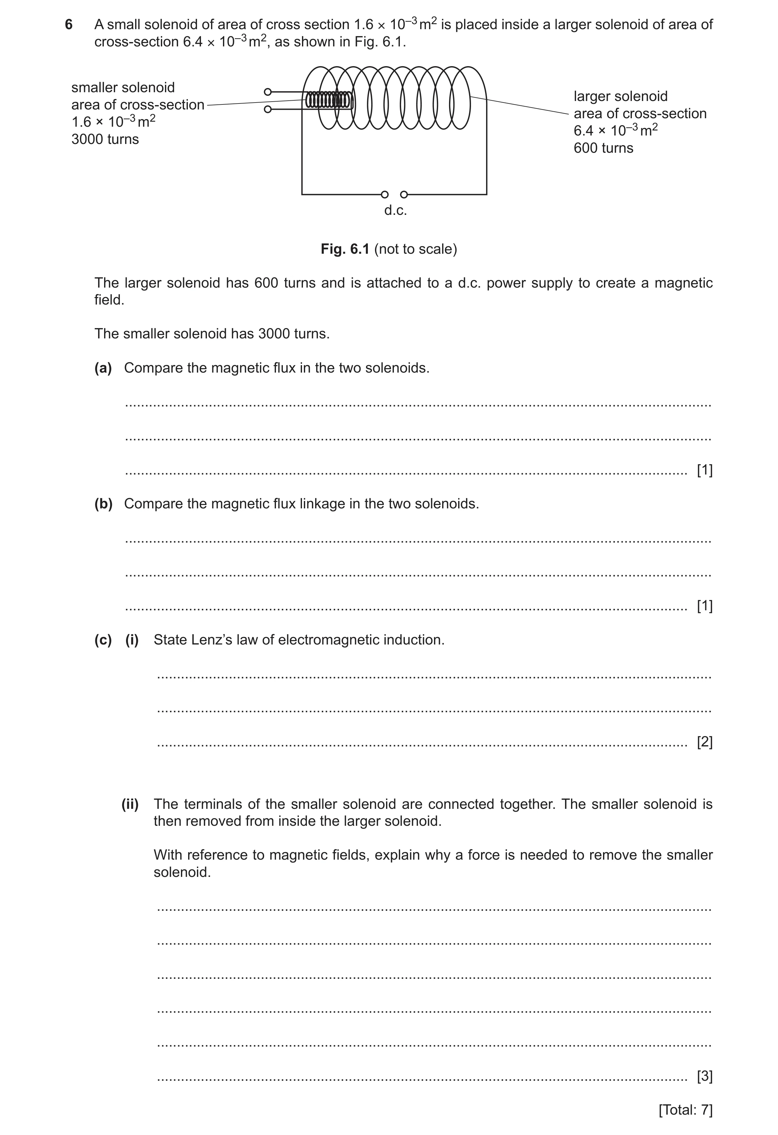
6 A small solenoid of area of cross section 1.6 × 10⁻³ m2 is placed inside a larger solenoid of area of cross-section 6.4 × 10⁻³ m2, as shown in Fig. 6.1. smaller solenoid larger solenoid area of cross-section area of cross-section 1.6 × 10⁻³ m2 6.4 × 10⁻³ m2 3000 turns 600 turns d.c. Fig. 6.1 (not to scale) The larger solenoid has 600 turns and is attached to a d.c. power supply to create a magnetic field. The smaller solenoid has 3000 turns. (a) Compare the magnetic flux in the two solenoids. … … … [1] (b) Compare the magnetic flux linkage in the two solenoids. … … … [1] (c) (i) State Lenz’s law of electromagnetic induction. … … … [2] (ii) The terminals of the smaller solenoid are connected together. The smaller solenoid is then removed from inside the larger solenoid. With reference to magnetic fields, explain why a force is needed to remove the smaller solenoid. … … … … … … [3] [Total: 7]
7 marks
Mark scheme: 6(a) less in smaller solenoid B1 6(b) greater in smaller solenoid B1 6(c)(i) direction of (induced) e.m.f. M1 such as to (produce effects that) oppose the change that caused it A1 6(c)(ii) change of flux (linkage) in smaller solenoid induces e.m.f. in smaller solenoid B1 (induced) current in smaller solenoid causes field around it B1 the two fields (interact to) create an attractive force B1
This question in 9702/42 Feb/March 2022
Question 32 9702/41 May/June 2022
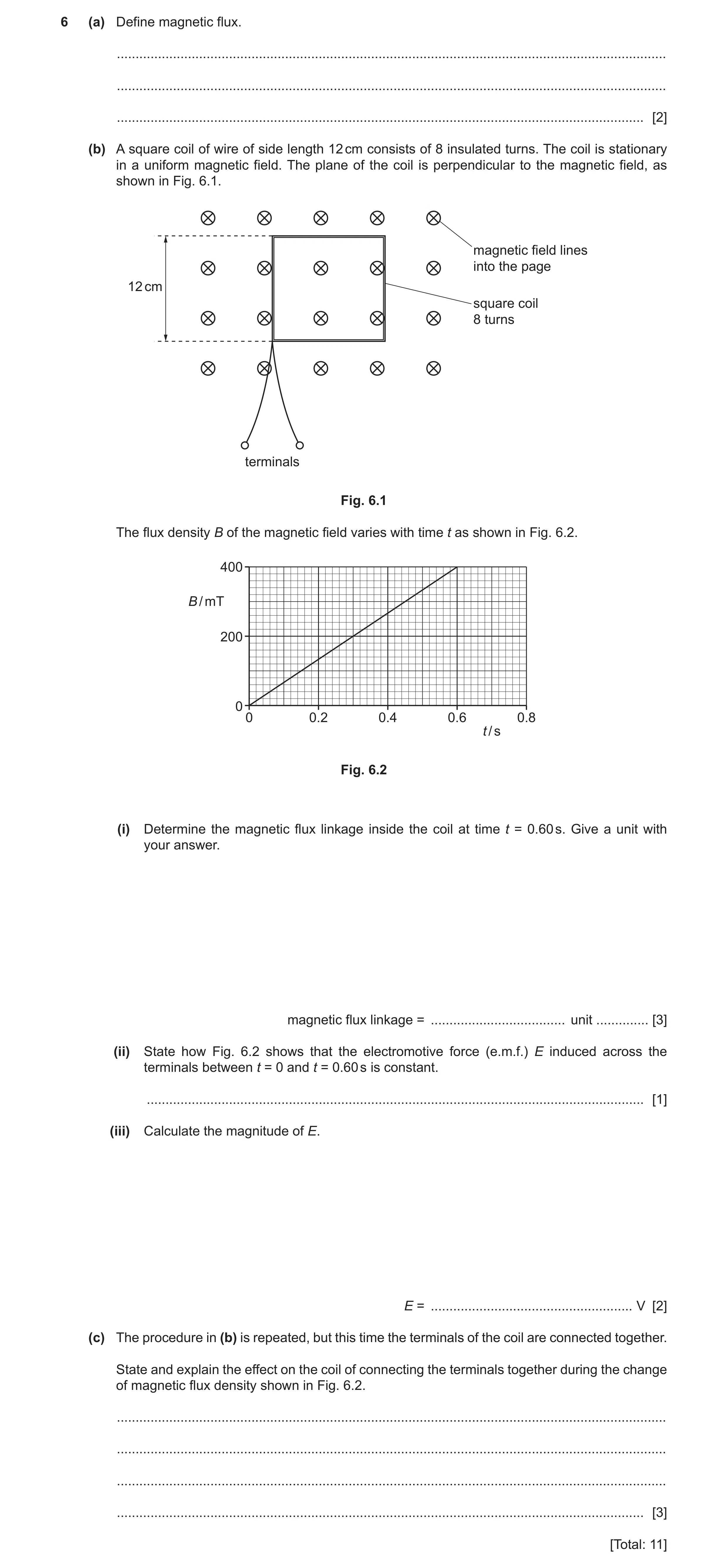
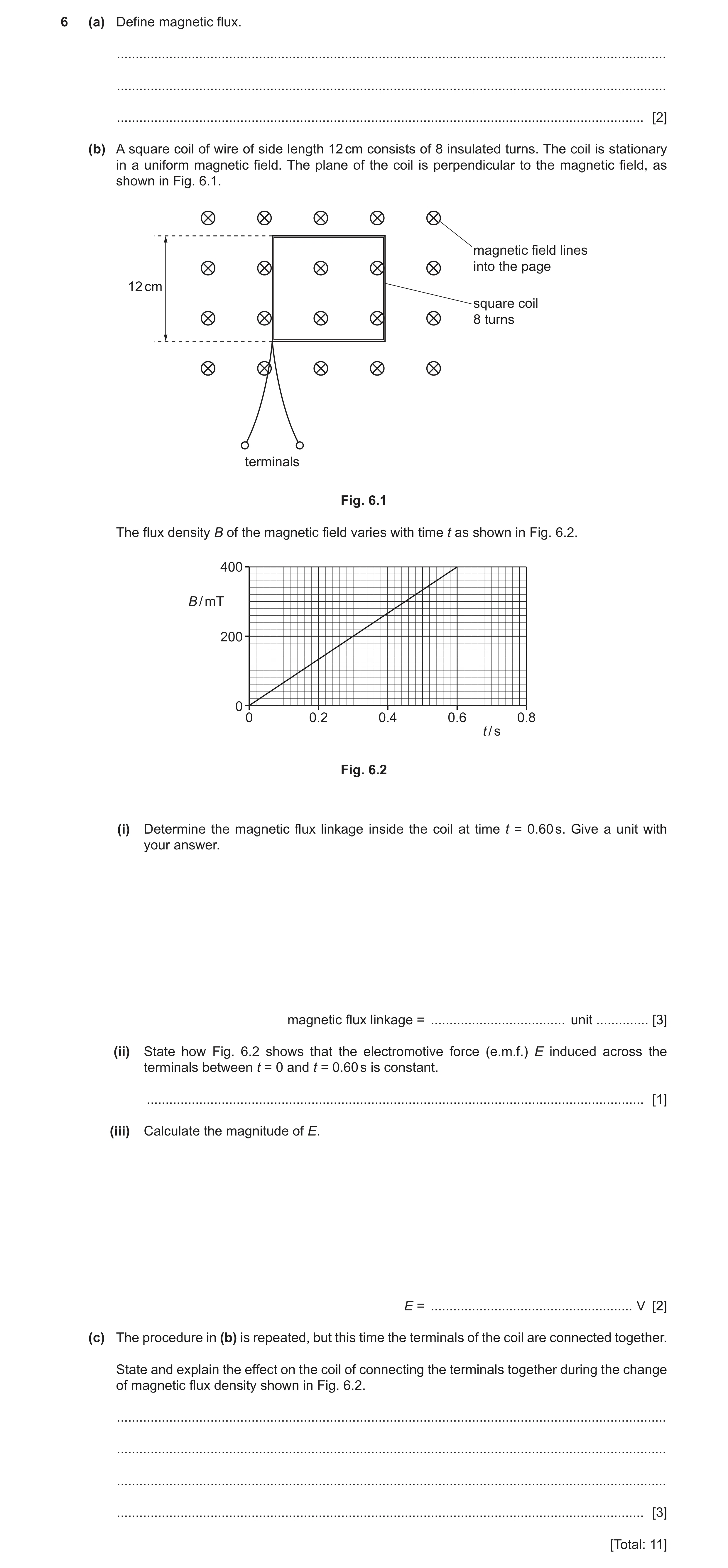
6 (a) Define magnetic flux. … … … [2] (b) A square coil of wire of side length 12 cm consists of 8 insulated turns. The coil is stationary in a uniform magnetic field. The plane of the coil is perpendicular to the magnetic field, as shown in Fig. 6.1. magnetic field lines into the page 12 cm square coil 8 turns terminals Fig. 6.1 The flux density B of the magnetic field varies with time t as shown in Fig. 6.2. 400 B / mT 200 0 0 0.2 0.4 0.6 0.8 t / s Fig. 6.2 (i) Determine the magnetic flux linkage inside the coil at time t = 0.60 s. Give a unit with your answer. magnetic flux linkage = … unit … [3] (ii) State how Fig. 6.2 shows that the electromotive force (e.m.f.) E induced across the terminals between t = 0 and t = 0.60 s is constant. … [1] (iii) Calculate the magnitude of E. E = … V [2] (c) The procedure in (b) is repeated, but this time the terminals of the coil are connected together. State and explain the effect on the coil of connecting the terminals together during the change of magnetic flux density shown in Fig. 6.2. … … … … [3] [Total: 11]
11 marks
Mark scheme: 6(a) product of (magnetic) flux density and area M1 where area is perpendicular to the (magnetic) field A1 6(b)(i) N = BAN C1 = 400 10–3 0.122 8 C1 = 0.046 Wb A1 6(b)(ii) (line is a) straight line B1 6(b)(iii) (induced) e.m.f. = rate of change of flux linkage C1 e.m.f. = N / t = 0.046 / 0.60 = 0.077 V A1 6(c) (induced e.m.f. causes) current flow (in the coil) B1 either current (in magnetic field) causes forces to act on the coil B1 (opposite sides of) coil forced inwards B1 or current causes dissipation of energy in the resistance of the coil (B1) temperature of the coil rises (B1)
This question in 9702/41 May/June 2022
Q33 · State Faraday’s law of electromagnetic induction 9702/42 May/June 2022
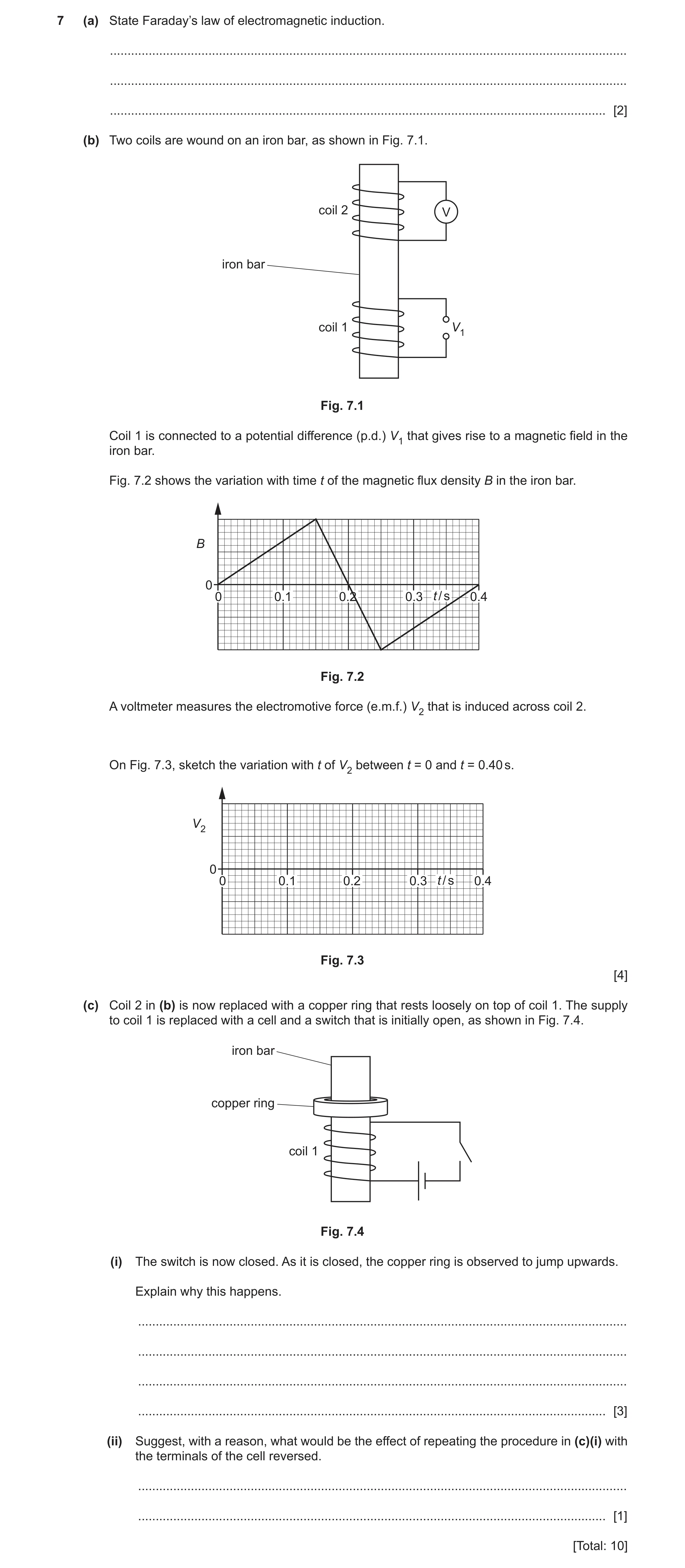
7 (a) State Faraday’s law of electromagnetic induction. … … … [2] (b) Two coils are wound on an iron bar, as shown in Fig. 7.1. coil 2 V iron bar coil 1 V1 Fig. 7.1 Coil 1 is connected to a potential difference (p.d.) V1 that gives rise to a magnetic field in the iron bar. Fig. 7.2 shows the variation with time t of the magnetic flux density B in the iron bar. B 0 0 0.1 0.2 0.3 t / s 0.4 Fig. 7.2 A voltmeter measures the electromotive force (e.m.f.) V2 that is induced across coil 2. On Fig. 7.3, sketch the variation with t of V2 between t = 0 and t = 0.40 s. V2 0 0 0.1 0.2 0.3 t / s 0.4 Fig. 7.3 [4] (c) Coil 2 in (b) is now replaced with a copper ring that rests loosely on top of coil 1. The supply to coil 1 is replaced with a cell and a switch that is initially open, as shown in Fig. 7.4. iron bar copper ring coil 1 Fig. 7.4 (i) The switch is now closed. As it is closed, the copper ring is observed to jump upwards. Explain why this happens. … … … … [3] (ii) Suggest, with a reason, what would be the effect of repeating the procedure in (c)(i) with the terminals of the cell reversed. … … [1] [Total: 10]
10 marks
Mark scheme: 7(a) induced e.m.f. is (directly) proportional to rate M1 of change of (magnetic) flux (linkage) A1 7(b) V2 stepped, all at non-zero values, between t = 0 and t = 0.40 s B1 V2 shown with same non-zero magnitude up to t = 0.15 s and after t = 0.25 s but with a different magnitude between these times B1 V2 shown with a magnitude between t = 0.15 s and t = 0.25 s that is three times the magnitude before t = 0.15 s and after t = 0.25 s B1 V2 shown with same sign up to t = 0.15 s and after t = 0.25 s, and opposite sign in between B1 7(c)(i) changing current in coil causes changing (magnetic) field or changing (magnetic) flux causes induced e.m.f. in ring B1 induced e.m.f. in ring causes current in ring B1 (magnetic) field due to (induced) current in ring interacts with (coil’s) field to cause upwards force (on ring) or (induced) current in ring perpendicular to (coil’s magnetic) field causes upwards force (on ring) B1 7(c)(ii) both magnetic fields reverse direction so ring still jumps up or current (in ring) and (coil’s) field both reverse so ring still jumps up B1
This question in 9702/42 May/June 2022
Question 34 9702/43 May/June 2022
6 (a) Define magnetic flux. … … … [2] (b) A square coil of wire of side length 12 cm consists of 8 insulated turns. The coil is stationary in a uniform magnetic field. The plane of the coil is perpendicular to the magnetic field, as shown in Fig. 6.1. magnetic field lines into the page 12 cm square coil 8 turns terminals Fig. 6.1 The flux density B of the magnetic field varies with time t as shown in Fig. 6.2. 400 B / mT 200 0 0 0.2 0.4 0.6 0.8 t / s Fig. 6.2 (i) Determine the magnetic flux linkage inside the coil at time t = 0.60 s. Give a unit with your answer. magnetic flux linkage = … unit … [3] (ii) State how Fig. 6.2 shows that the electromotive force (e.m.f.) E induced across the terminals between t = 0 and t = 0.60 s is constant. … [1] (iii) Calculate the magnitude of E. E = … V [2] (c) The procedure in (b) is repeated, but this time the terminals of the coil are connected together. State and explain the effect on the coil of connecting the terminals together during the change of magnetic flux density shown in Fig. 6.2. … … … … [3] [Total: 11]
11 marks
Mark scheme: 6(a) product of (magnetic) flux density and area M1 where area is perpendicular to the (magnetic) field A1 6(b)(i) N = BAN C1 = 400 10–3 0.122 8 C1 = 0.046 Wb A1 6(b)(ii) (line is a) straight line B1 6(b)(iii) (induced) e.m.f. = rate of change of flux linkage C1 e.m.f. = N / t = 0.046 / 0.60 = 0.077 V A1 6(c) (induced e.m.f. causes) current flow (in the coil) B1 either current (in magnetic field) causes forces to act on the coil B1 (opposite sides of) coil forced inwards B1 or current causes dissipation of energy in the resistance of the coil (B1) temperature of the coil rises (B1)
This question in 9702/43 May/June 2022
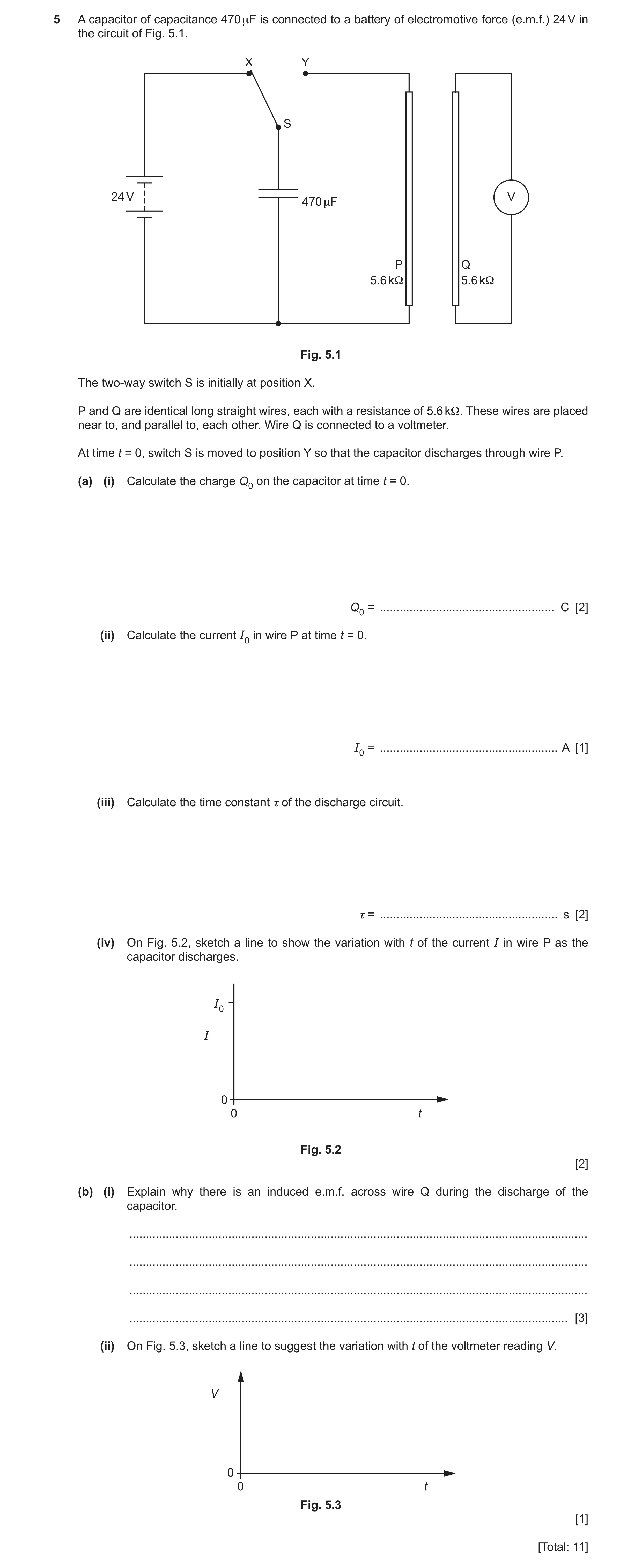
Q35 · A capacitor of capacitance 470 μF is connected to a battery of electromotive force… 9702/41 Oct/Nov 2022
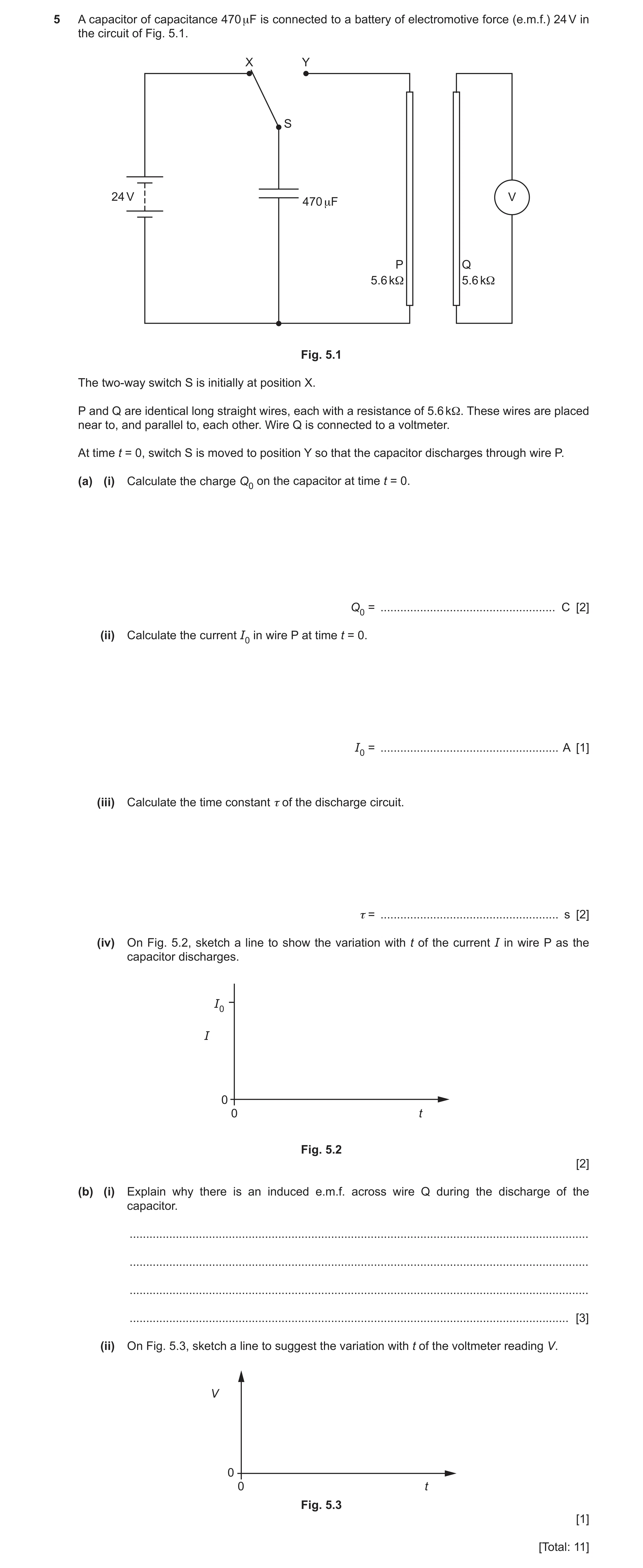
5 A capacitor of capacitance 470 μF is connected to a battery of electromotive force (e.m.f.) 24 V in the circuit of Fig. 5.1. X Y S 24 V V 470 μF P Q 5.6 kΩ 5.6 kΩ Fig. 5.1 The two-way switch S is initially at position X. P and Q are identical long straight wires, each with a resistance of 5.6 kΩ. These wires are placed near to, and parallel to, each other. Wire Q is connected to a voltmeter. At time t = 0, switch S is moved to position Y so that the capacitor discharges through wire P. (a) (i) Calculate the charge Q0 on the capacitor at time t = 0. Q0 = … C [2] (ii) Calculate the current I0 in wire P at time t = 0. I0 = … A [1] (iii) Calculate the time constant τ of the discharge circuit. τ = … s [2] (iv) On Fig. 5.2, sketch a line to show the variation with t of the current I in wire P as the capacitor discharges. I0 I 0 0 t Fig. 5.2 [2] (b) (i) Explain why there is an induced e.m.f. across wire Q during the discharge of the capacitor. … … … … [3] (ii) On Fig. 5.3, sketch a line to suggest the variation with t of the voltmeter reading V. V 0 0 t Fig. 5.3 [1] [Total: 11]
11 marks
Mark scheme: 5(a)(i) Q = CV C1 Q0 = 24 470 10–6 A1 = 0.011 C 5(a)(ii) I0 = 24 / 5600 A1 = 4.3 10–3 A 5(a)(iii) = RC C1 = 5600 470 10–6 A1 = 2.6 s 5(a)(iv) line with negative gradient throughout passing through (0, I0) B1 exponential decay curve asymptotic to t-axis B1 5(b)(i) current in wire P gives rise to a magnetic field B1 as current (in P) changes, wire Q cuts (magnetic) flux (of wire P) B1 cutting magnetic flux causes induced e.m.f. (across Q) B1 5(b)(ii) sketch shows line with a negative gradient throughout B1
This question in 9702/41 Oct/Nov 2022
Q36 · State Lenz’s law of electromagnetic induction 9702/42 Oct/Nov 2022
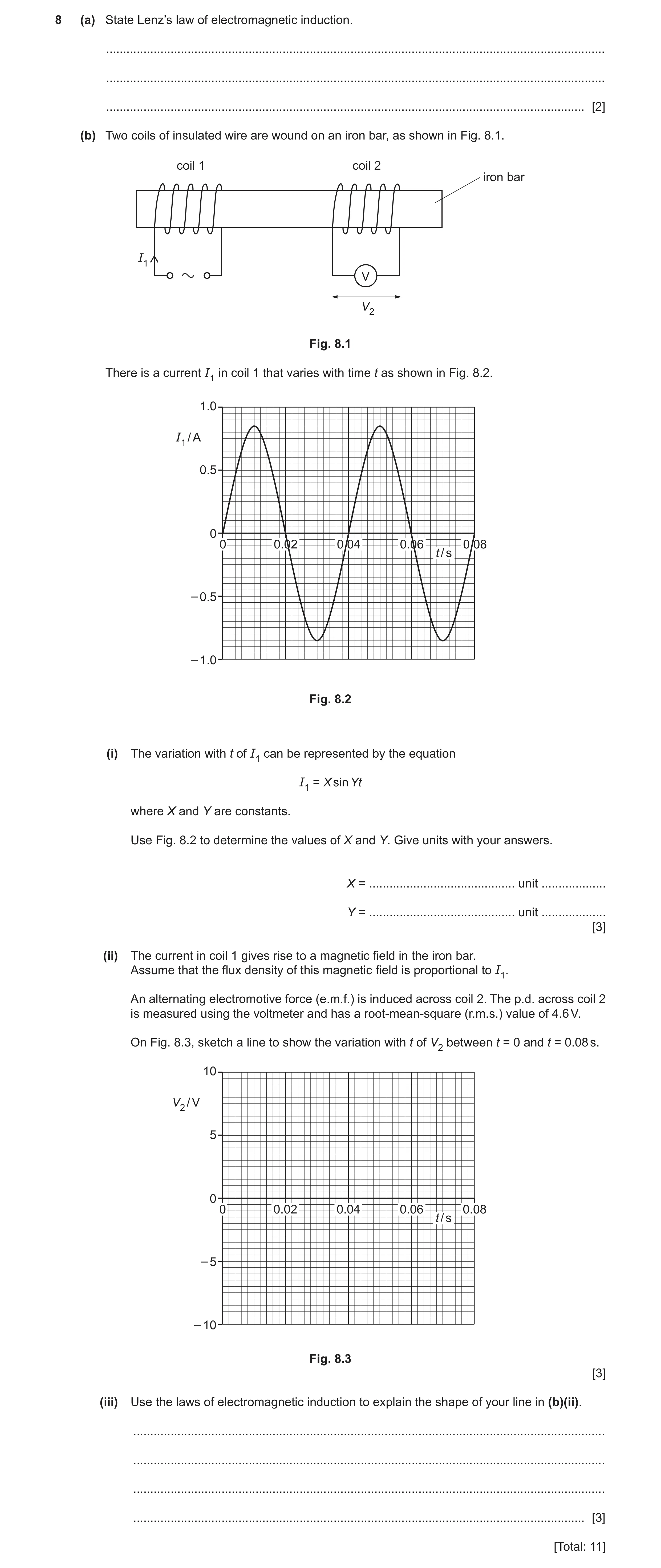
8 (a) State Lenz’s law of electromagnetic induction. … … … [2] (b) Two coils of insulated wire are wound on an iron bar, as shown in Fig. 8.1. coil 1 coil 2 iron bar I1 V V2 Fig. 8.1 There is a current I1 in coil 1 that varies with time t as shown in Fig. 8.2. 1.0 I1 / A 0.5 0 0 0.02 0.04 0.06 0.08 t / s – 0.5 – 1.0 Fig. 8.2 (i) The variation with t of I1 can be represented by the equation I1 = X sin Yt where X and Y are constants. Use Fig. 8.2 to determine the values of X and Y. Give units with your answers. X = … unit … Y = … unit … [3] (ii) The current in coil 1 gives rise to a magnetic field in the iron bar. Assume that the flux density of this magnetic field is proportional to I1. An alternating electromotive force (e.m.f.) is induced across coil 2. The p.d. across coil 2 is measured using the voltmeter and has a root-mean-square (r.m.s.) value of 4.6 V. On Fig. 8.3, sketch a line to show the variation with t of V2 between t = 0 and t = 0.08 s. 10 V2 / V 5 0 0 0.02 0.04 0.06 0.08 t / s – 5 – 10 Fig. 8.3 [3] (iii) Use the laws of electromagnetic induction to explain the shape of your line in (b)(ii). … … … … [3] [Total: 11]
11 marks
Mark scheme: 8(a) direction of induced e.m.f. M1 such as to (produce effects that) oppose the change that caused it A1 8(b)(i) X = 0.85 A A1 Y = 2 / 0.040 C1 = 160 rad s–1 A1 8(b)(ii) two cycles of a sinusoidal curve with a period of 0.040 s B1 correct phase (i.e. V2 max / min at t = 0, 0.02, 0.04, 0.06 and 0.08 s, and V2 zero at t = 0.01, 0.03, 0.05, 0.07 s) B1 maximum / minimum V2 shown (consistently) at ± 6.5 V B1 8(b)(iii) (magnitude of) V2 is proportional to rate of change of (magnetic) flux B1 • V2 is proportional to gradient of I1–t curve B2 • V2 has maximum magnitude when I1–t curve is steepest • V2 is zero when I1–t curve is horizontal / a maximum or minimum • V2 changes sign when sign of gradient of I1–t curve changes Any two points, 1 mark each
This question in 9702/42 Oct/Nov 2022
Q37 · A capacitor of capacitance 470 μF is connected to a battery of electromotive force… 9702/43 Oct/Nov 2022
5 A capacitor of capacitance 470 μF is connected to a battery of electromotive force (e.m.f.) 24 V in the circuit of Fig. 5.1. X Y S 24 V V 470 μF P Q 5.6 kΩ 5.6 kΩ Fig. 5.1 The two-way switch S is initially at position X. P and Q are identical long straight wires, each with a resistance of 5.6 kΩ. These wires are placed near to, and parallel to, each other. Wire Q is connected to a voltmeter. At time t = 0, switch S is moved to position Y so that the capacitor discharges through wire P. (a) (i) Calculate the charge Q0 on the capacitor at time t = 0. Q0 = … C [2] (ii) Calculate the current I0 in wire P at time t = 0. I0 = … A [1] (iii) Calculate the time constant τ of the discharge circuit. τ = … s [2] (iv) On Fig. 5.2, sketch a line to show the variation with t of the current I in wire P as the capacitor discharges. I0 I 0 0 t Fig. 5.2 [2] (b) (i) Explain why there is an induced e.m.f. across wire Q during the discharge of the capacitor. … … … … [3] (ii) On Fig. 5.3, sketch a line to suggest the variation with t of the voltmeter reading V. V 0 0 t Fig. 5.3 [1] [Total: 11]
11 marks
Mark scheme: 5(a)(i) Q = CV C1 Q0 = 24 470 10–6 A1 = 0.011 C 5(a)(ii) I0 = 24 / 5600 A1 = 4.3 10–3 A 5(a)(iii) = RC C1 = 5600 470 10–6 A1 = 2.6 s 5(a)(iv) line with negative gradient throughout passing through (0, I0) B1 exponential decay curve asymptotic to t-axis B1 5(b)(i) current in wire P gives rise to a magnetic field B1 as current (in P) changes, wire Q cuts (magnetic) flux (of wire P) B1 cutting magnetic flux causes induced e.m.f. (across Q) B1 5(b)(ii) sketch shows line with a negative gradient throughout B1
This question in 9702/43 Oct/Nov 2022
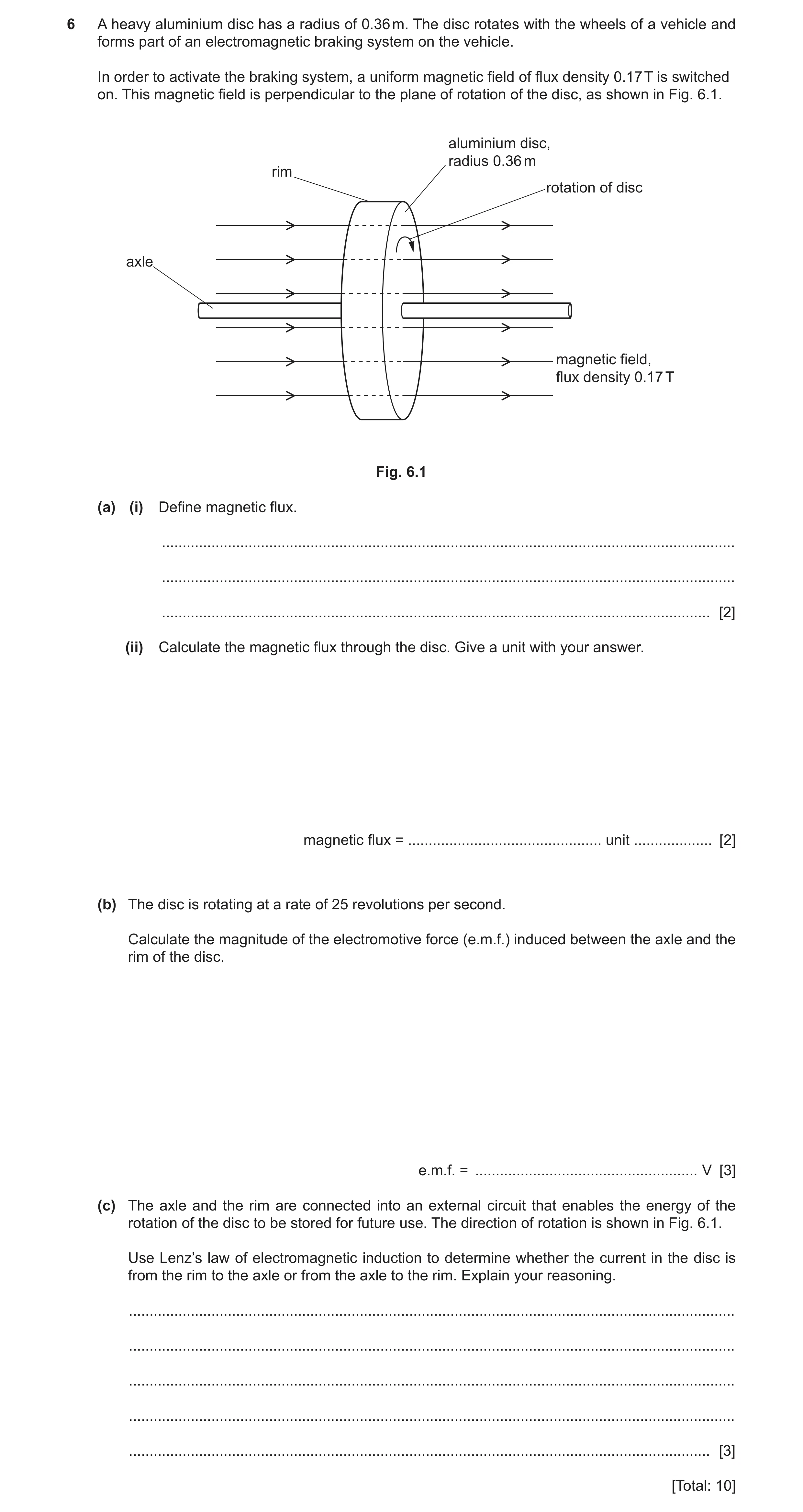
Q38 · A heavy aluminium disc has a radius of 0.36 m 9702/42 May/June 2023
6 A heavy aluminium disc has a radius of 0.36 m. The disc rotates with the wheels of a vehicle and forms part of an electromagnetic braking system on the vehicle. In order to activate the braking system, a uniform magnetic field of flux density 0.17 T is switched on. This magnetic field is perpendicular to the plane of rotation of the disc, as shown in Fig. 6.1. aluminium disc, radius 0.36 m rim rotation of disc axle magnetic field, flux density 0.17 T Fig. 6.1 (a) (i) Define magnetic flux. … … … [2] (ii) Calculate the magnetic flux through the disc. Give a unit with your answer. magnetic flux = … unit … [2] (b) The disc is rotating at a rate of 25 revolutions per second. Calculate the magnitude of the electromotive force (e.m.f.) induced between the axle and the rim of the disc. e.m.f. = … V [3] (c) The axle and the rim are connected into an external circuit that enables the energy of the rotation of the disc to be stored for future use. The direction of rotation is shown in Fig. 6.1. Use Lenz’s law of electromagnetic induction to determine whether the current in the disc is from the rim to the axle or from the axle to the rim. Explain your reasoning. … … … … … [3] [Total: 10]
10 marks
Mark scheme: 6(a)(i) product of (magnetic) flux density and area M1 area perpendicular to the (magnetic) field A1 6(a)(ii) flux = B r2 = 0.17 0.362 C1 = 6.9 10–2 Wb A1 6(b) time for one revolution = 1 / 25 s C1 e.m.f. = rate of cutting flux or / t C1 = 0.069 25 = 1.7 V A1 6(c) current (in disc) is perpendicular to magnetic field or current causes force to act on disc B1 force opposes rotation of disc B1 left-hand rule indicates current is from rim to axle B1
This question in 9702/42 May/June 2023
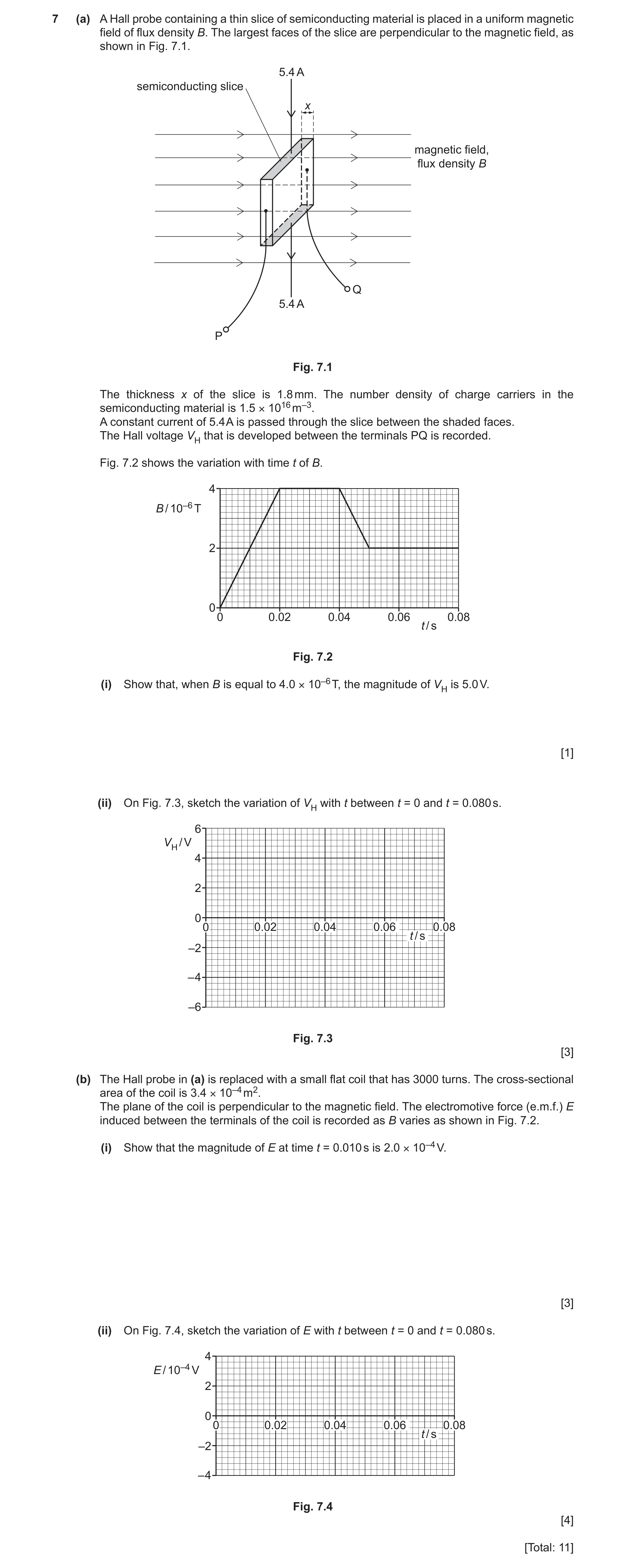
Q39 · A Hall probe containing a thin slice of semiconducting material is placed in a uniform… 9702/42 Oct/Nov 2023
7 (a) A Hall probe containing a thin slice of semiconducting material is placed in a uniform magnetic field of flux density B. The largest faces of the slice are perpendicular to the magnetic field, as shown in Fig. 7.1. 5.4 A semiconducting slice x magnetic field, flux density B Q 5.4 A P Fig. 7.1 The thickness x of the slice is 1.8 mm. The number density of charge carriers in the semiconducting material is 1.5 × 10¹⁶ m–3. A constant current of 5.4 A is passed through the slice between the shaded faces. The Hall voltage VH that is developed between the terminals PQ is recorded. Fig. 7.2 shows the variation with time t of B. 4 B / 10–6 T 2 0 0 0.02 0.04 0.06 0.08 t / s Fig. 7.2 (i) Show that, when B is equal to 4.0 × 10⁻⁶ T, the magnitude of VH is 5.0 V. [1] (ii) On Fig. 7.3, sketch the variation of VH with t between t = 0 and t = 0.080 s. 6 VH / V 4 2 0 0 0.02 0.04 0.06 0.08 t / s –2 – 4 –6 Fig. 7.3 [3] (b) The Hall probe in (a) is replaced with a small flat coil that has 3000 turns. The cross-sectional area of the coil is 3.4 × 10⁻⁴ m2. The plane of the coil is perpendicular to the magnetic field. The electromotive force (e.m.f.) E induced between the terminals of the coil is recorded as B varies as shown in Fig. 7.2. (i) Show that the magnitude of E at time t = 0.010 s is 2.0 × 10⁻⁴ V. [3] (ii) On Fig. 7.4, sketch the variation of E with t between t = 0 and t = 0.080 s. 4 E / 10–4 V 2 0 0 0.02 0.04 0.06 0.08 t / s –2 – 4 Fig. 7.4 [4] [Total: 11]
11 marks
Mark scheme: 7(a)(i) VH = BI / ntq A1 = (4.0 10–6 5.4) / (1.5 1016 1.8 10–3 1.60 10–19) = 5.0 V 7(a)(ii) sketch: straight diagonal line from (0, 0) to t = 0.020 s B1 and straight diagonal line between two non-zero VH values of same sign from t = 0.040 to 0.050 s horizontal straight line at VH = 5.0 V from t = 0.020 to 0.040 s B1 horizontal straight line at VH = 2.5 V from t = 0.050 to 0.080 s B1 7(b)(i) e.m.f. = rate of change of (magnetic) flux (linkage) C1 E = NA ΔB / Δt or E = NA gradient (at t = 0.010 s) C1 E = 3000 3.4 10–4 (4.0 10–6) / (0.020) = 2.0 10–4 V A1 7(b)(ii) sketch: line showing non-zero E from t = 0 to t = 0.020 s and from t = 0.040 s to t = 0.050 s, and E = 0 at all other times B1 ‘top hats’ showing constant non-zero E from t = 0 to t = 0.020 s and from t = 0.040 s to t = 0.050 s B1 magnitude of E shown as 2.0 10–4 V in both non-zero sections B1 sign of E in the t = 0 to t = 0.020 s region opposite to the sign of E in the t = 0.040 s to t = 0.050 s region B1
This question in 9702/42 Oct/Nov 2023
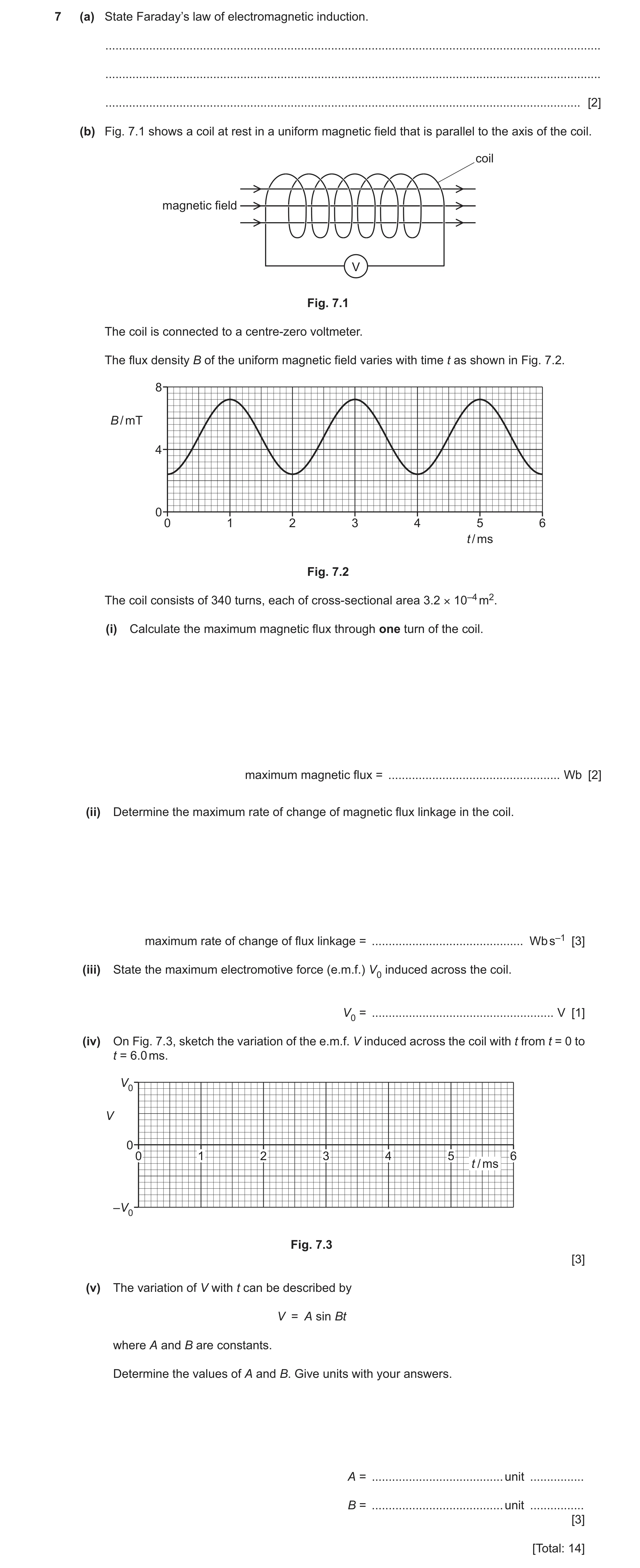
Q40 · State Faraday’s law of electromagnetic induction 9702/42 May/June 2024
7 (a) State Faraday’s law of electromagnetic induction. … … … [2] (b) Fig. 7.1 shows a coil at rest in a uniform magnetic field that is parallel to the axis of the coil. coil magnetic field V Fig. 7.1 The coil is connected to a centre-zero voltmeter. The flux density B of the uniform magnetic field varies with time t as shown in Fig. 7.2. 8 B / mT 4 0 0 1 2 3 4 5 6 t / ms Fig. 7.2 The coil consists of 340 turns, each of cross-sectional area 3.2 × 10⁻⁴ m2. (i) Calculate the maximum magnetic flux through one turn of the coil. maximum magnetic flux = … Wb [2] (ii) Determine the maximum rate of change of magnetic flux linkage in the coil. maximum rate of change of flux linkage = … Wb s–1 [3] (iii) State the maximum electromotive force (e.m.f.) V0 induced across the coil. V0 = … V [1] (iv) On Fig. 7.3, sketch the variation of the e.m.f. V induced across the coil with t from t = 0 to t = 6.0 ms. V0 V 0 0 1 2 3 4 5 6 t / ms –V0 Fig. 7.3 [3] (v) The variation of V with t can be described by V = A sin Bt where A and B are constants. Determine the values of A and B. Give units with your answers. A = … unit … B = … unit … [3] [Total: 14]
14 marks
Mark scheme: 7(a) (induced) e.m.f. is (directly) proportional to rate M1 of change of (magnetic) flux (linkage) A1 7(b)(i) = BA C1 = 7.2 10–3 3.2 10–4 = 2.3 10–6 Wb A1 7(b)(ii) tangent drawn at steepest point on Fig. 7.2 C1 evidence of multiplication by 340 C1 maximum rate of change of flux = 0.82 Wb s–1 A1 7(b)(iii) V0 = 0.82 V or V0 given as identical numerical answer to the answer in (b)(ii) A1 7(b)(iv) sinusoidal curve of period 2.0 ms from t = 0 to t = 6.0 ms B1 all peaks at +V0 and all troughs at –V0 B1 line showing V = 0 at (and only at) t = 0, 1.0, 2.0, 3.0, 4.0, 5.0 and 6.0 ms B1 7(b)(v) A = 0.82 V or A has same numerical value as answer in (b)(iii), with unit V A1 B = 2 / (2.0 10–3) C1 = 3100 rad s–1 A1
This question in 9702/42 May/June 2024
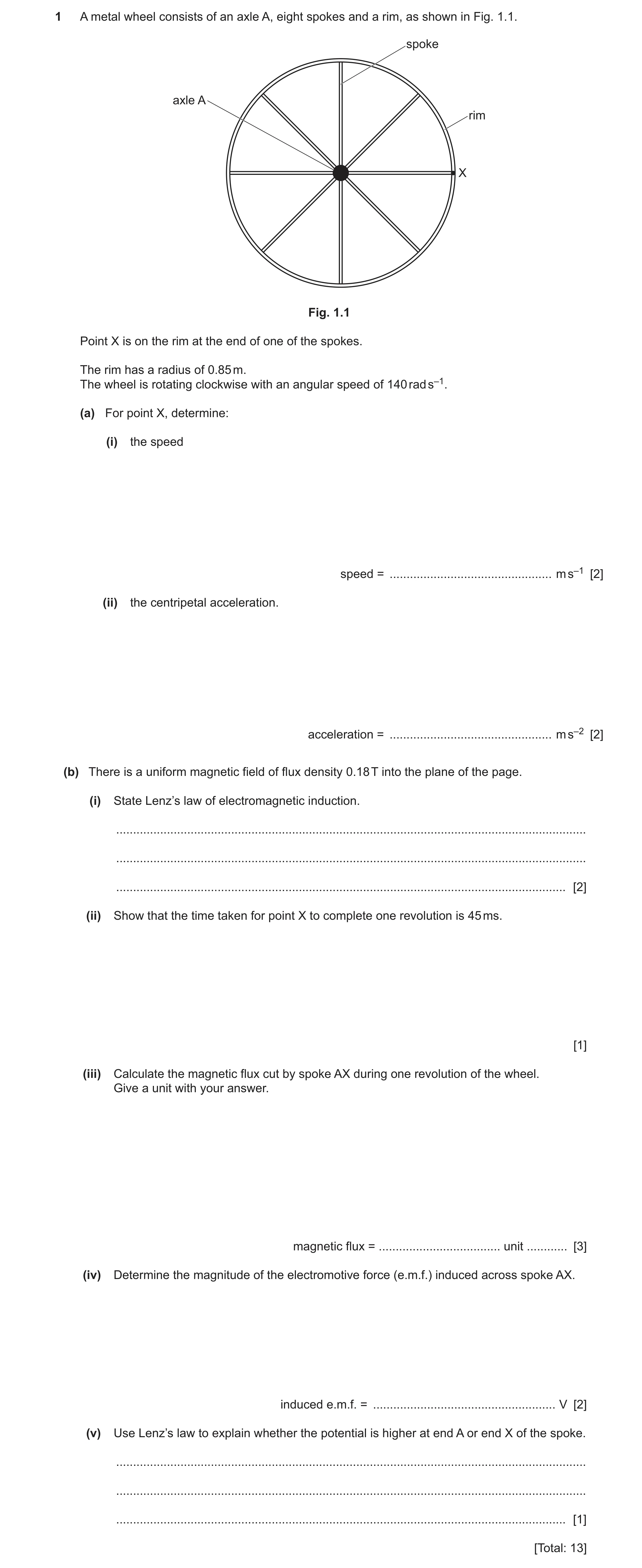
Q41 · A metal wheel consists of an axle A, eight spokes and a rim, as shown in Fig 9702/42 Oct/Nov 2024
1 A metal wheel consists of an axle A, eight spokes and a rim, as shown in Fig. 1.1. spoke axle A rim X Fig. 1.1 Point X is on the rim at the end of one of the spokes. The rim has a radius of 0.85 m. The wheel is rotating clockwise with an angular speed of 140 rad s–1. (a) For point X, determine: (i) the speed speed = … m s–1 [2] (ii) the centripetal acceleration. acceleration = … m s–2 [2] (b) There is a uniform magnetic field of flux density 0.18 T into the plane of the page. (i) State Lenz’s law of electromagnetic induction. … … … [2] (ii) Show that the time taken for point X to complete one revolution is 45 ms. [1] (iii) Calculate the magnetic flux cut by spoke AX during one revolution of the wheel. Give a unit with your answer. magnetic flux = … unit … [3] (iv) Determine the magnitude of the electromotive force (e.m.f.) induced across spoke AX. induced e.m.f. = … V [2] (v) Use Lenz’s law to explain whether the potential is higher at end A or end X of the spoke. … … … [1] [Total: 13]
13 marks
Mark scheme: Question Answer Marks 1(a)(i) v = r C1 = 0.85 140 A1 = 120 m s–1 1(a)(ii) a = r2 or a = v2 / r C1 a = 0.85 1402 or 1202 / 0.85 A1 = 1.7 104 m s–2 1(b)(i) direction of (induced) e.m.f. M1 is such as to (produce effects that) oppose the change that caused it A1 1(b)(ii) T = 2 / A1 = 2 / 140 = 0.045 s = 45 ms 1(b)(iii) = BA C1 = 0.18 0.852 C1 = 0.41 Wb A1 1(b)(iv) E = / t C1 = 0.41 / 0.045 A1 = 9.1 V 1(b)(v) force (on spoke) must be anticlockwise, so current is from A to X (by Fleming’s left hand rule), so X is at the higher potential B1
This question in 9702/42 Oct/Nov 2024
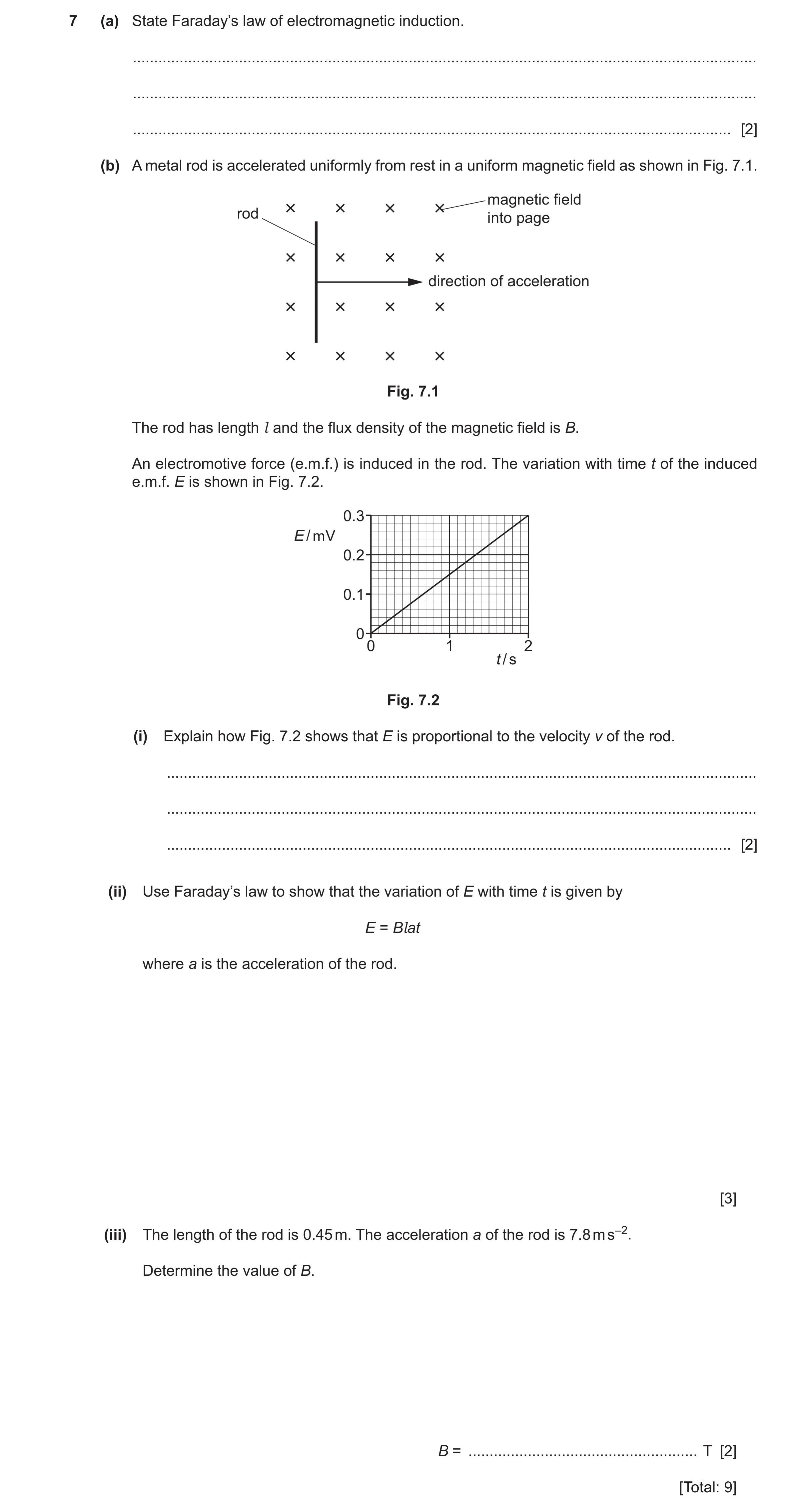
Q42 · State Faraday’s law of electromagnetic induction 9702/42 Feb/March 2025
7 (a) State Faraday’s law of electromagnetic induction. … … … [2] (b) A metal rod is accelerated uniformly from rest in a uniform magnetic field as shown in Fig. 7.1. magnetic field rod into page direction of acceleration Fig. 7.1 The rod has length l and the flux density of the magnetic field is B. An electromotive force (e.m.f.) is induced in the rod. The variation with time t of the induced e.m.f. E is shown in Fig. 7.2. 0.3 E / mV 0.2 0.1 0 0 1 2 t / s Fig. 7.2 (i) Explain how Fig. 7.2 shows that E is proportional to the velocity v of the rod. … … … [2] (ii) Use Faraday’s law to show that the variation of E with time t is given by E = Blat where a is the acceleration of the rod. [3] (iii) The length of the rod is 0.45 m. The acceleration a of the rod is 7.8 m s–2. Determine the value of B. B = … T [2] [Total: 9]
9 marks
Mark scheme: 7(a) (induced) e.m.f. is (directly) proportional to rate M1 of change of (magnetic) flux (linkage) A1 7(b)(i) (uniform acceleration so) velocity is (directly) proportional to time M1 (Fig. 7.2 shows) e.m.f. is (directly) proportional to time so E is proportional to v. A1 7(b)(ii) (v = at so) distance moved in time t = att C1 = BA C1 E = ( / t) = B L (att) / t = BLat A1 7(b)(iii) B = (0.30 10–3) / (0.45 7.8 2.0) C1 = 4.3 10–5 T A1
This question in 9702/42 Feb/March 2025
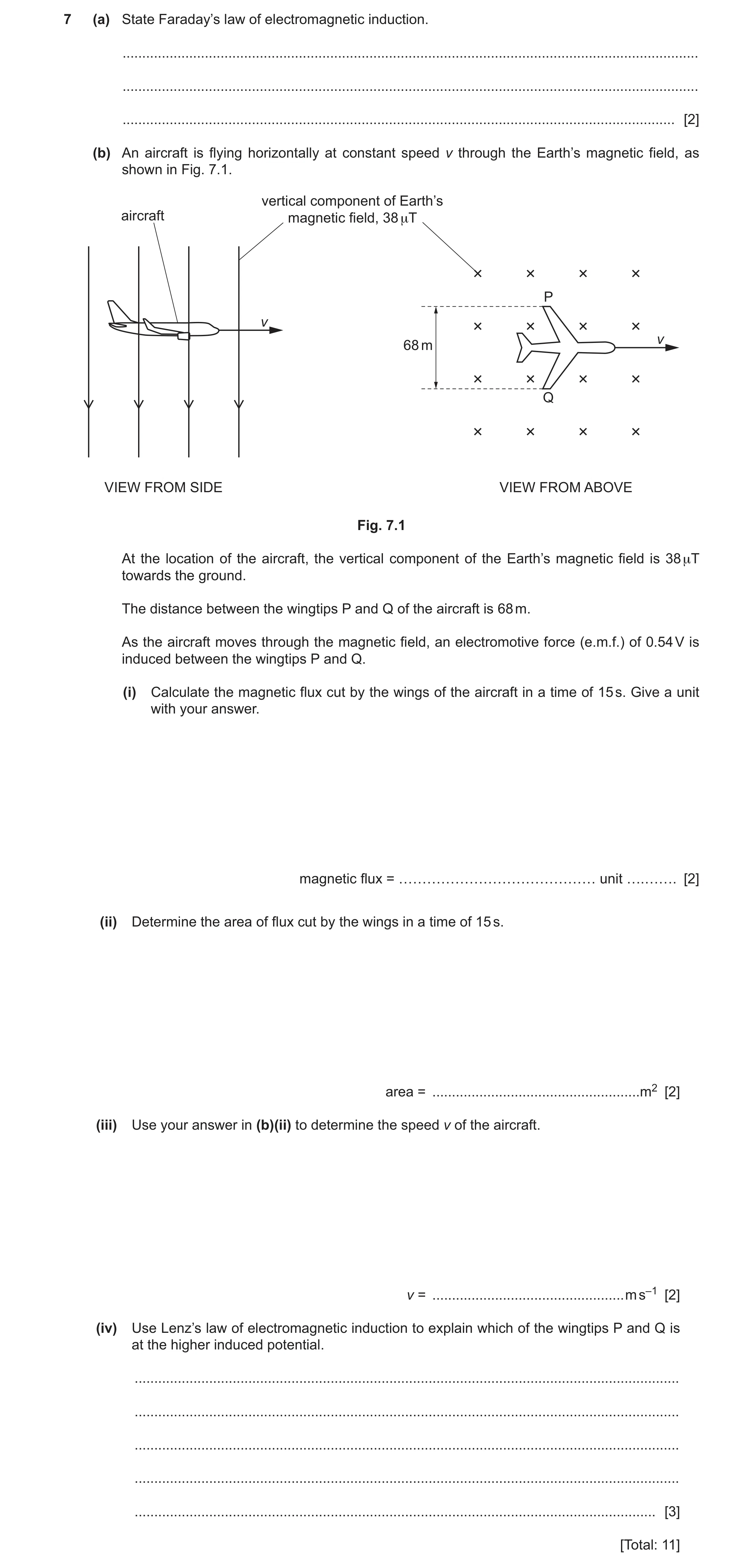
Q43 · State Faraday’s law of electromagnetic induction 9702/41 Oct/Nov 2025
7 (a) State Faraday’s law of electromagnetic induction. … … … [2] (b) An aircraft is flying horizontally at constant speed v through the Earth’s magnetic field, as shown in Fig. 7.1. vertical component of Earth’s aircraft magnetic field, 38 μT P v v 68 m Q VIEW FROM SIDE VIEW FROM ABOVE Fig. 7.1 At the location of the aircraft, the vertical component of the Earth’s magnetic field is 38 μT towards the ground. The distance between the wingtips P and Q of the aircraft is 68 m. As the aircraft moves through the magnetic field, an electromotive force (e.m.f.) of 0.54 V is induced between the wingtips P and Q. (i) Calculate the magnetic flux cut by the wings of the aircraft in a time of 15 s. Give a unit with your answer. magnetic flux = …………………………………… unit ….……. [2] (ii) Determine the area of flux cut by the wings in a time of 15 s. area = … m2 [2] (iii) Use your answer in (b)(ii) to determine the speed v of the aircraft. v = … m s–1 [2] (iv) Use Lenz’s law of electromagnetic induction to explain which of the wingtips P and Q is at the higher induced potential. … … … … … [3] [Total: 11]
11 marks
Mark scheme: 7(a) (induced) e.m.f. is (directly) proportional to rate M1 of change of (magnetic) flux (linkage) A1 7(b)(i) flux = e.m.f. time C1 flux = 0.54 15 A1 = 8.1 Wb 7(b)(ii) = BA C1 area = 8.1 / (38 10–6) A1 = 2.1 105 m2 7(b)(iii) area = speed time width C1 v = (2.1 105) / (15 68) A1 = 210 m s–1 7(b)(iv) opposing force (due to current in wings) must be backwards B1 from Fleming’s left-hand rule, current (in wings) must be from Q to P B1 current is from – to + inside an e.m.f. source so P is at higher potential B1
This question in 9702/41 Oct/Nov 2025
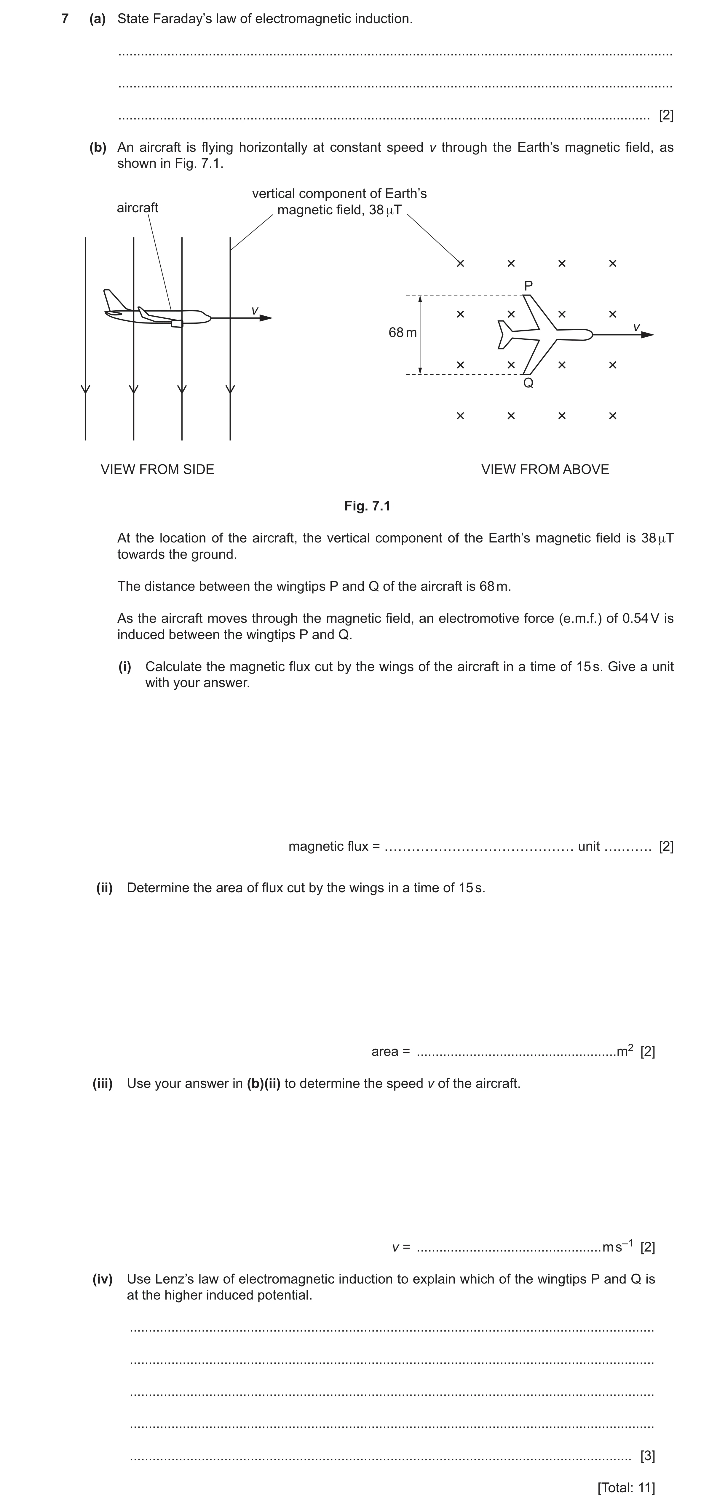
Q44 · State Faraday’s law of electromagnetic induction 9702/43 Oct/Nov 2025
7 (a) State Faraday’s law of electromagnetic induction. … … … [2] (b) An aircraft is flying horizontally at constant speed v through the Earth’s magnetic field, as shown in Fig. 7.1. vertical component of Earth’s aircraft magnetic field, 38 μT P v v 68 m Q VIEW FROM SIDE VIEW FROM ABOVE Fig. 7.1 At the location of the aircraft, the vertical component of the Earth’s magnetic field is 38 μT towards the ground. The distance between the wingtips P and Q of the aircraft is 68 m. As the aircraft moves through the magnetic field, an electromotive force (e.m.f.) of 0.54 V is induced between the wingtips P and Q. (i) Calculate the magnetic flux cut by the wings of the aircraft in a time of 15 s. Give a unit with your answer. magnetic flux = …………………………………… unit ….……. [2] (ii) Determine the area of flux cut by the wings in a time of 15 s. area = … m2 [2] (iii) Use your answer in (b)(ii) to determine the speed v of the aircraft. v = … m s–1 [2] (iv) Use Lenz’s law of electromagnetic induction to explain which of the wingtips P and Q is at the higher induced potential. … … … … … [3] [Total: 11]
11 marks
Mark scheme: 7(a) (induced) e.m.f. is (directly) proportional to rate M1 of change of (magnetic) flux (linkage) A1 7(b)(i) flux = e.m.f. time C1 flux = 0.54 15 A1 = 8.1 Wb 7(b)(ii) = BA C1 area = 8.1 / (38 10–6) A1 = 2.1 105 m2 7(b)(iii) area = speed time width C1 v = (2.1 105) / (15 68) A1 = 210 m s–1 7(b)(iv) opposing force (due to current in wings) must be backwards B1 from Fleming’s left-hand rule, current (in wings) must be from Q to P B1 current is from – to + inside an e.m.f. source so P is at higher potential B1
This question in 9702/43 Oct/Nov 2025
Q45 · State Lenz’s law of electromagnetic induction 9702/44 Oct/Nov 2025
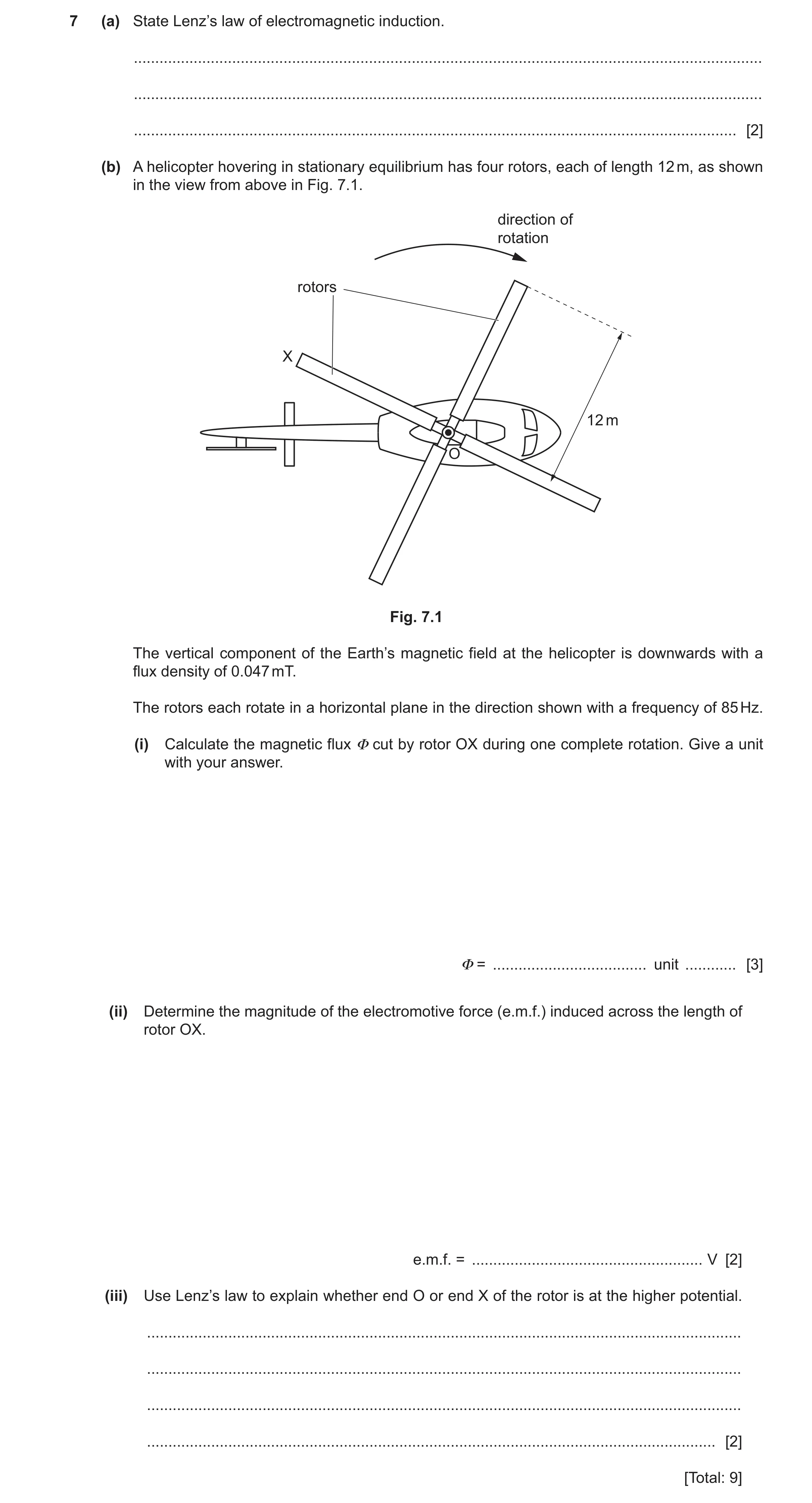
7 (a) State Lenz’s law of electromagnetic induction. … … … [2] (b) A helicopter hovering in stationary equilibrium has four rotors, each of length 12 m, as shown in the view from above in Fig. 7.1. direction of rotation rotors X 12 m O Fig. 7.1 The vertical component of the Earth’s magnetic field at the helicopter is downwards with a flux density of 0.047 mT. The rotors each rotate in a horizontal plane in the direction shown with a frequency of 85 Hz. (i) Calculate the magnetic flux Φ cut by rotor OX during one complete rotation. Give a unit with your answer. Φ = … unit … [3] (ii) Determine the magnitude of the electromotive force (e.m.f.) induced across the length of rotor OX. e.m.f. = … V [2] (iii) Use Lenz’s law to explain whether end O or end X of the rotor is at the higher potential. … … … … [2] [Total: 9]
9 marks
Mark scheme: 7(a) direction of induced e.m.f. M1 such as to (produce effects that) oppose the change that caused it A1 7(b)(i) = BA C1 = 0.047 10–3 122 C1 = 0.021 Wb A1 7(b)(ii) e.m.f. = flux cut / time C1 = 0.021 / (1 / 85) A1 = 1.8 V 7(b)(iii) force (due to current) cause anticlockwise moment (to oppose rotation) B1 (from the LH rule) current is from O to X, so X is at the higher potential B1
This question in 9702/44 Oct/Nov 2025
 3 / 70
 4 / 70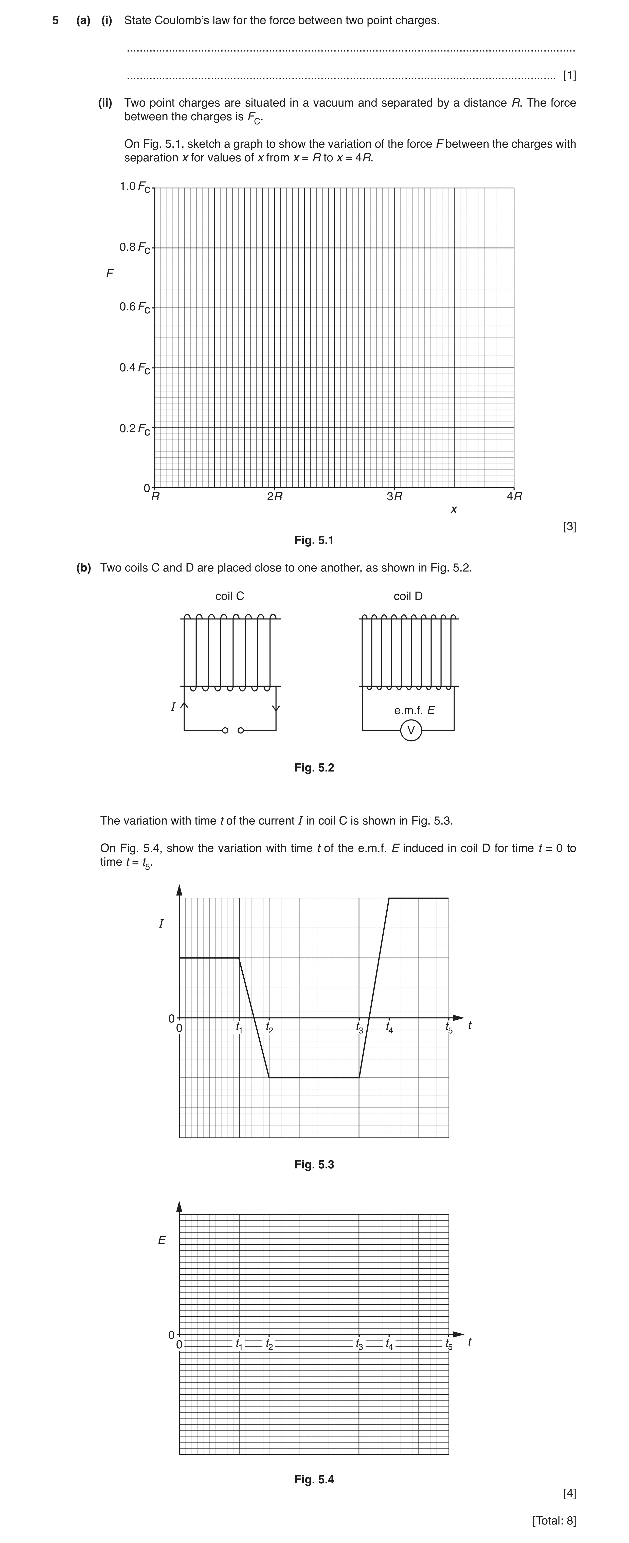
 11 / 70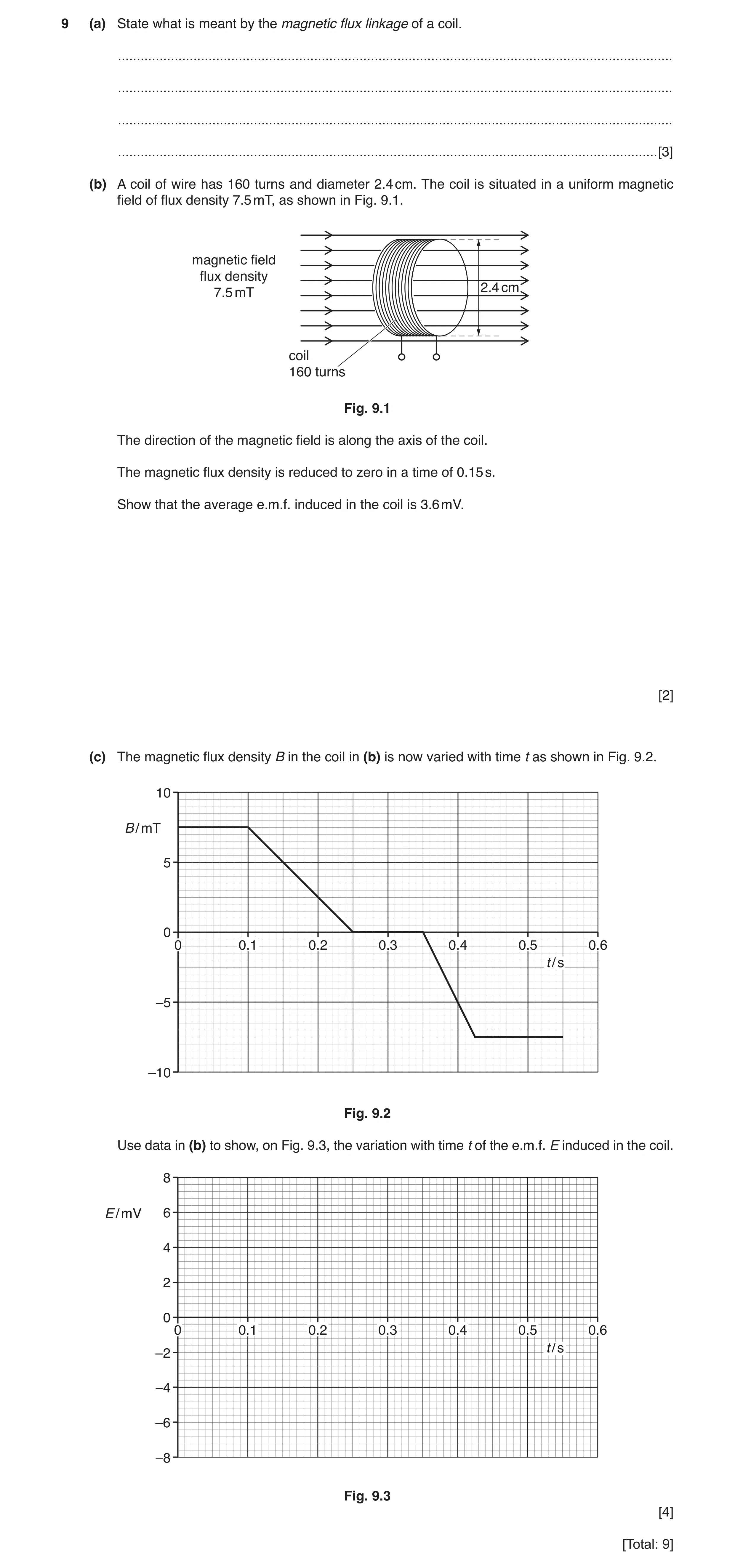
 14 / 70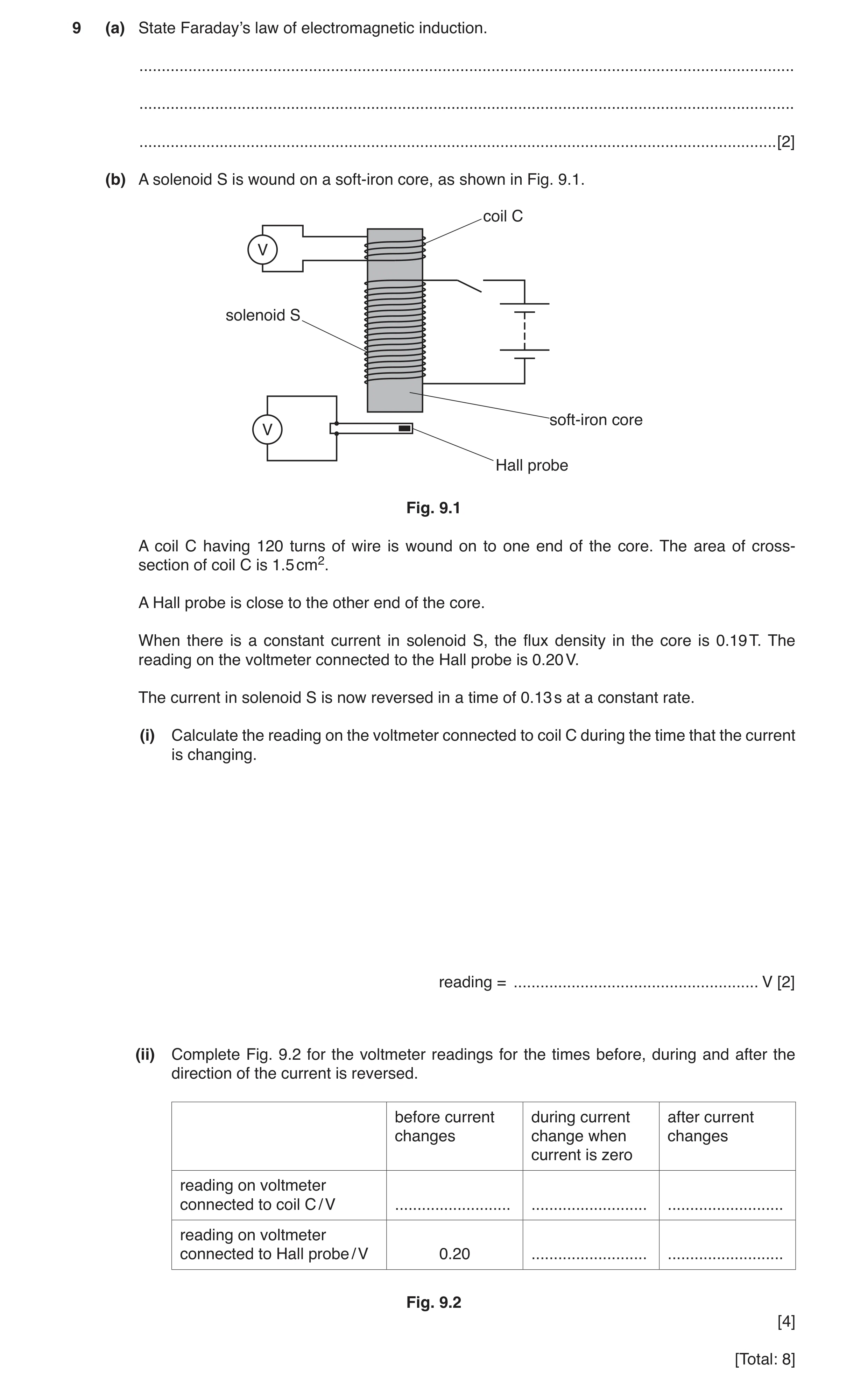
 20 / 70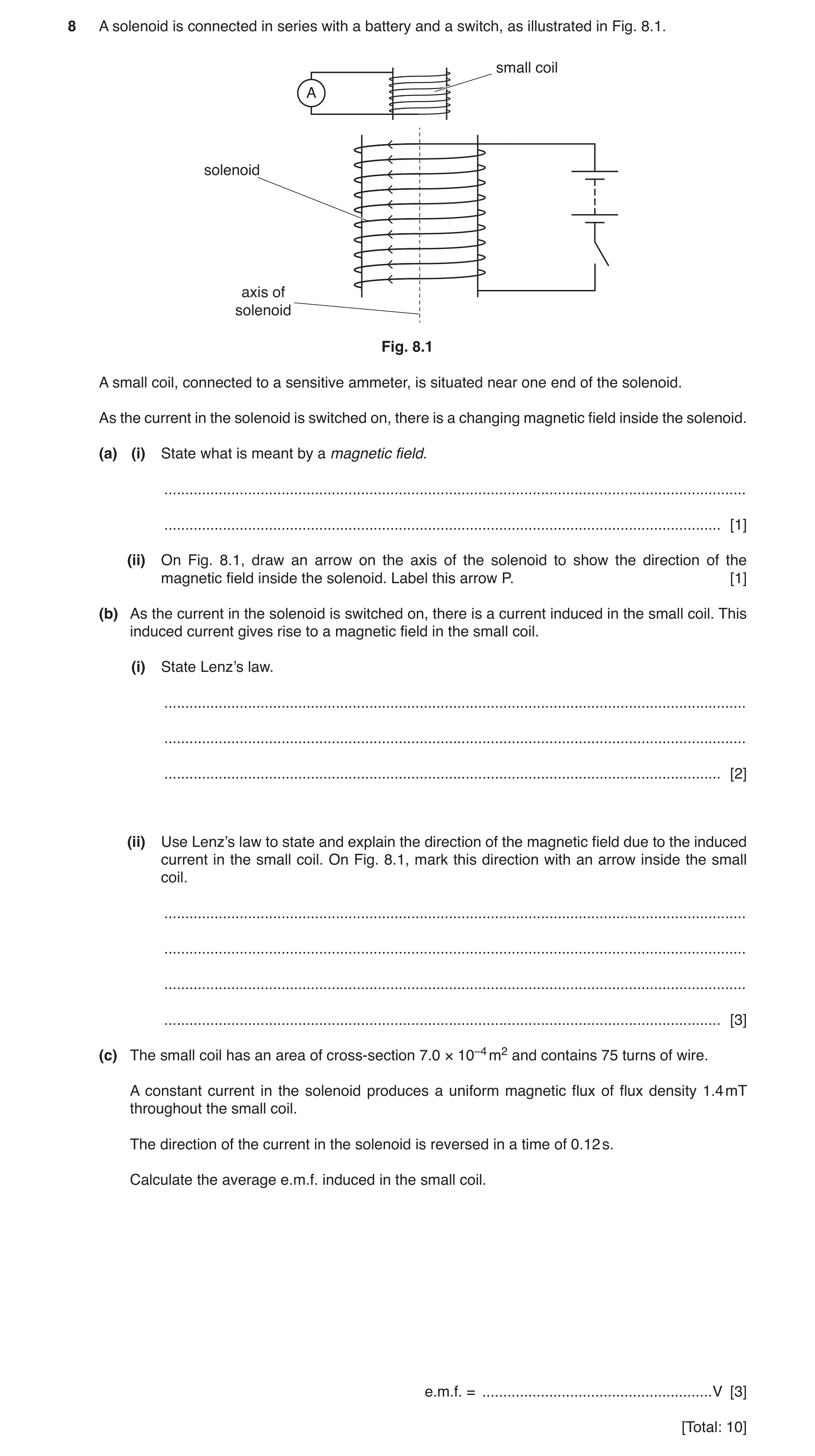
 28 / 70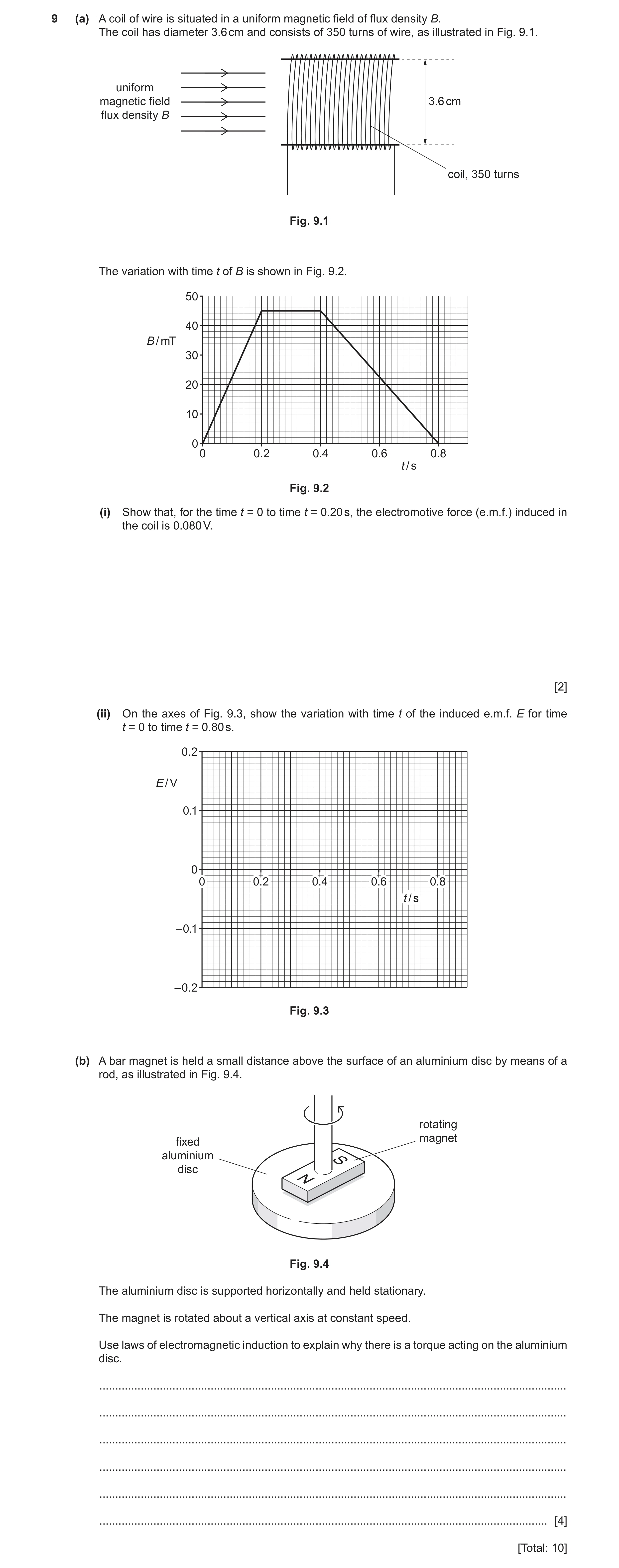
 11
11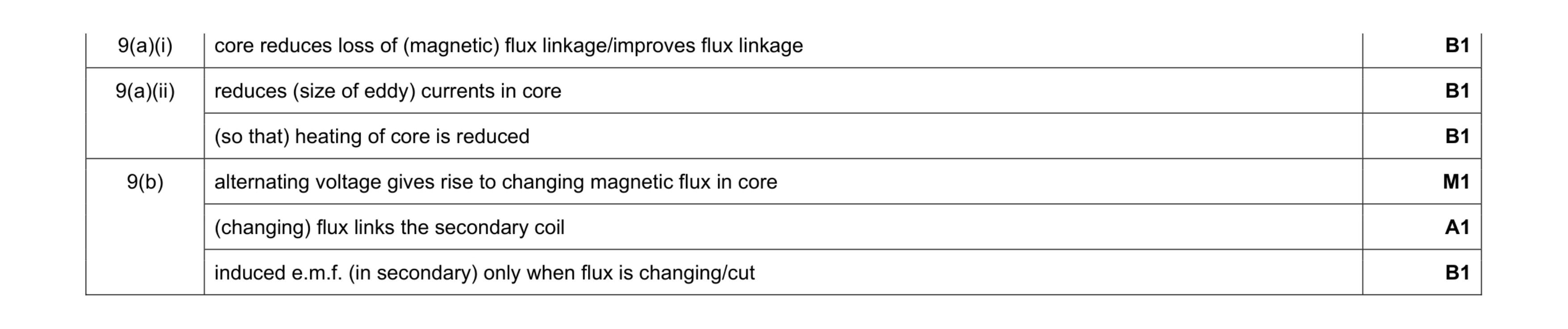 6
6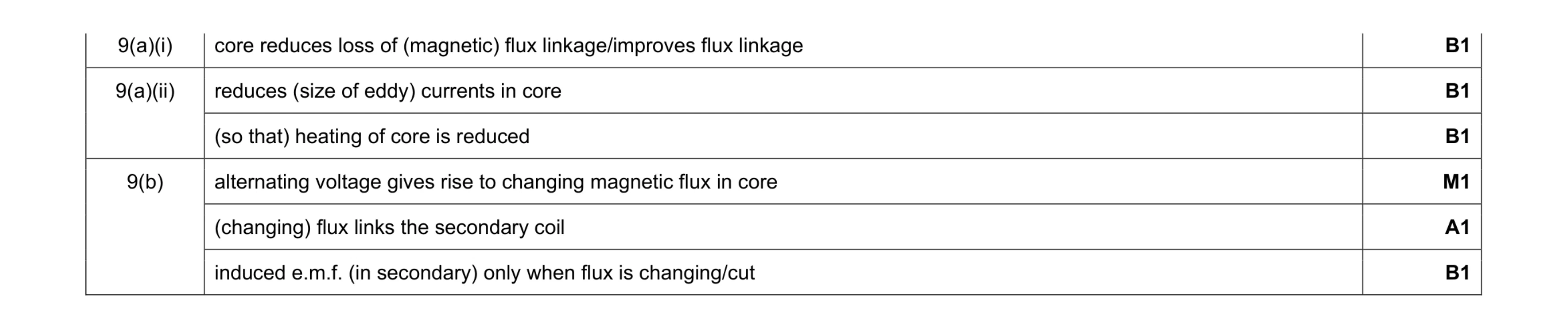 6
6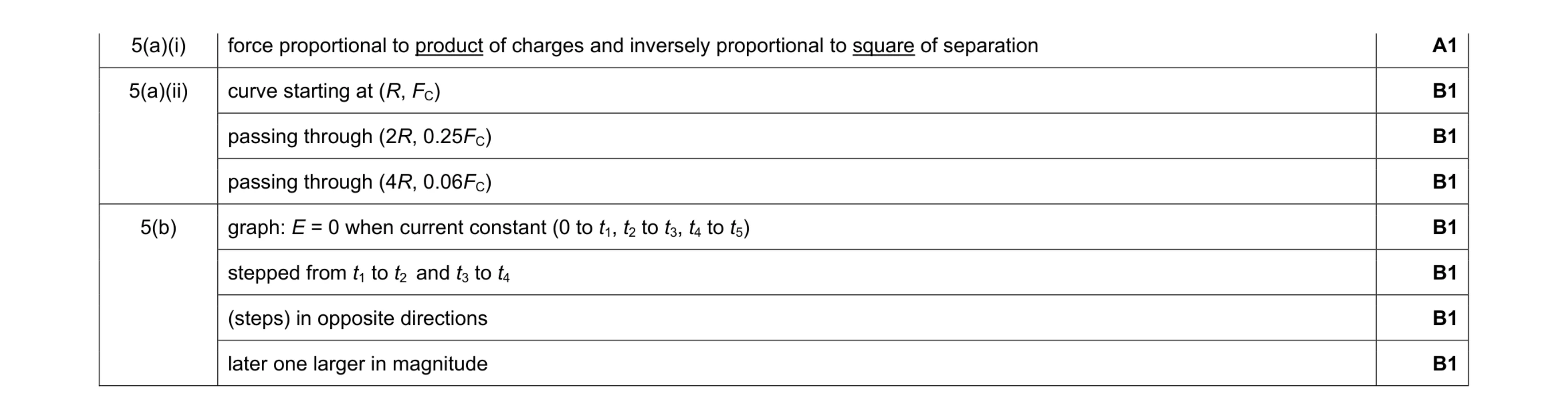 8
8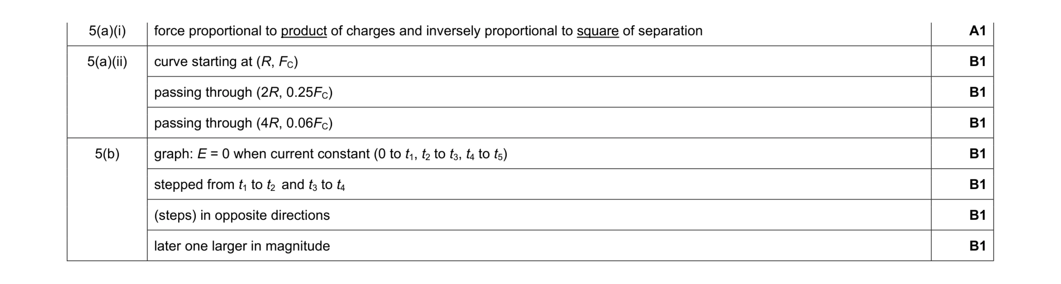 8
8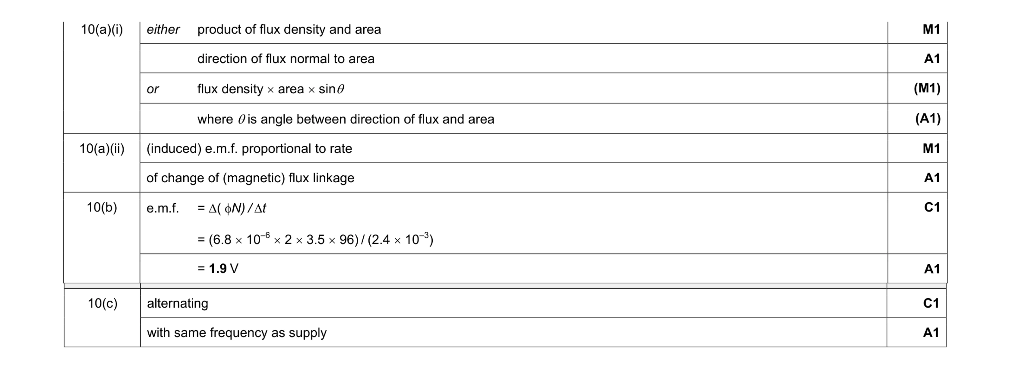 8
8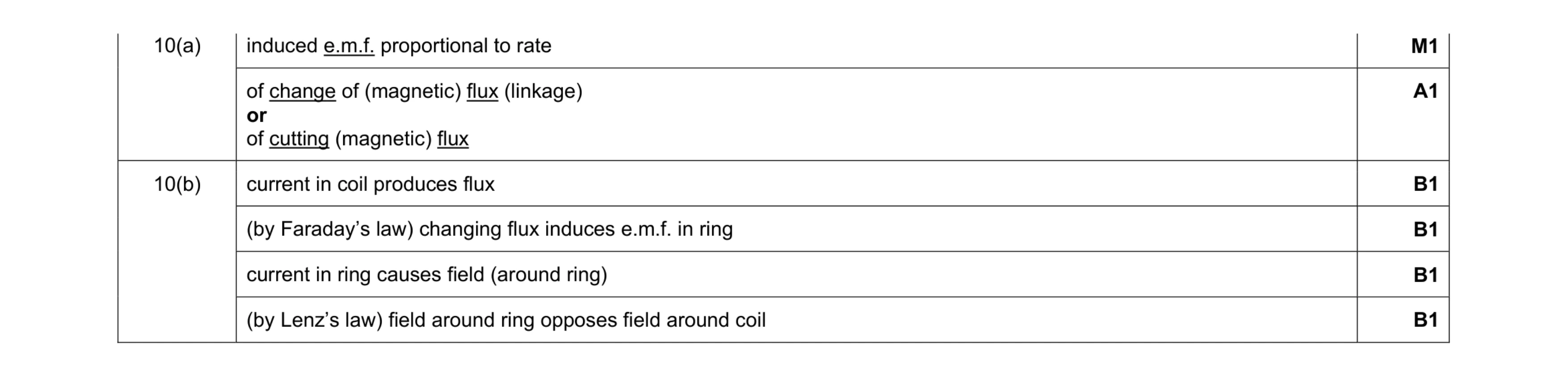 6
6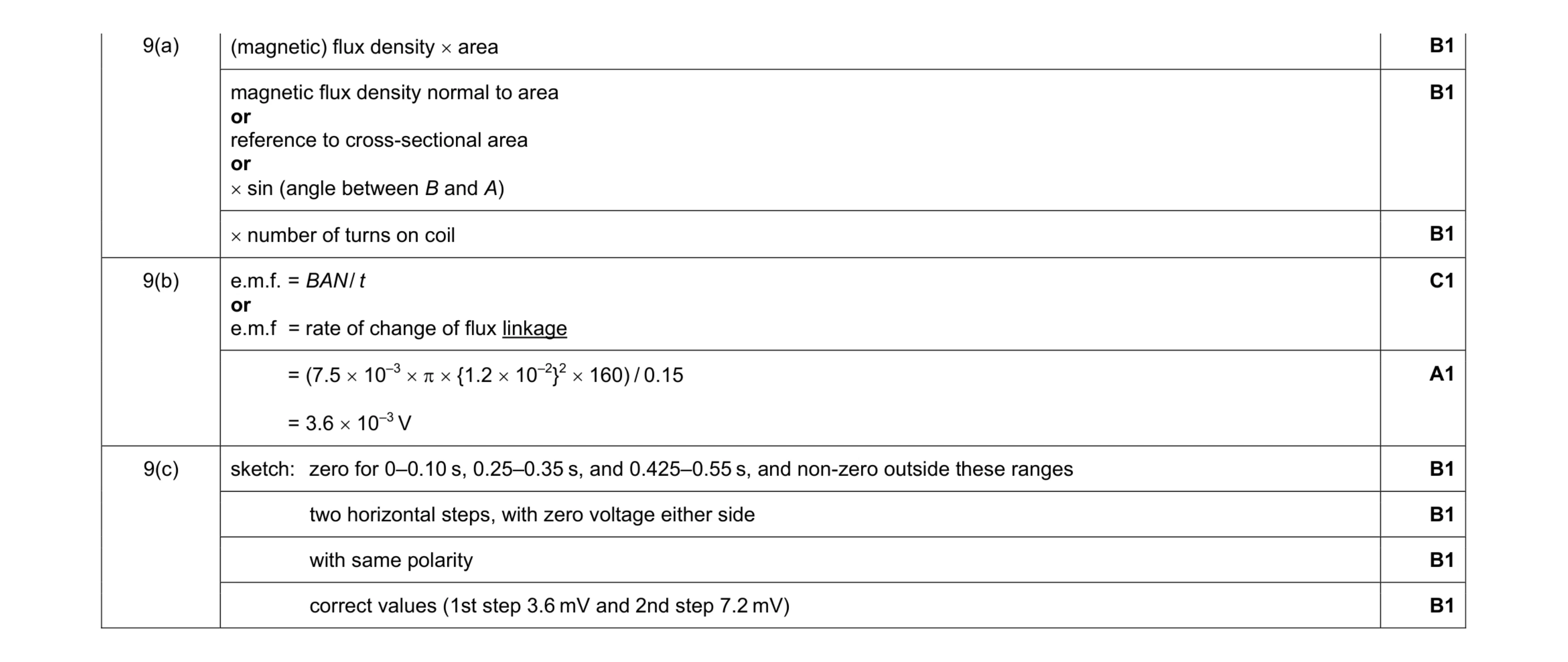 9
9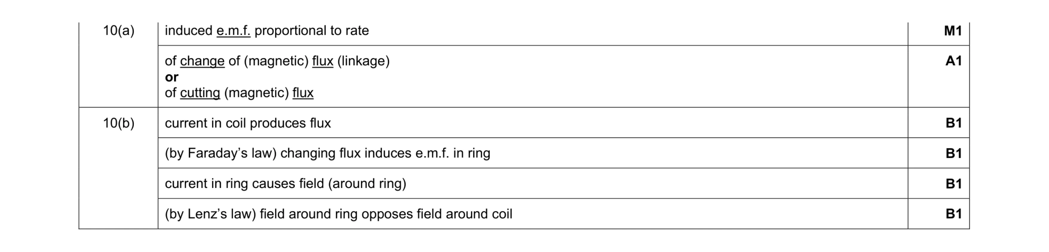 6
6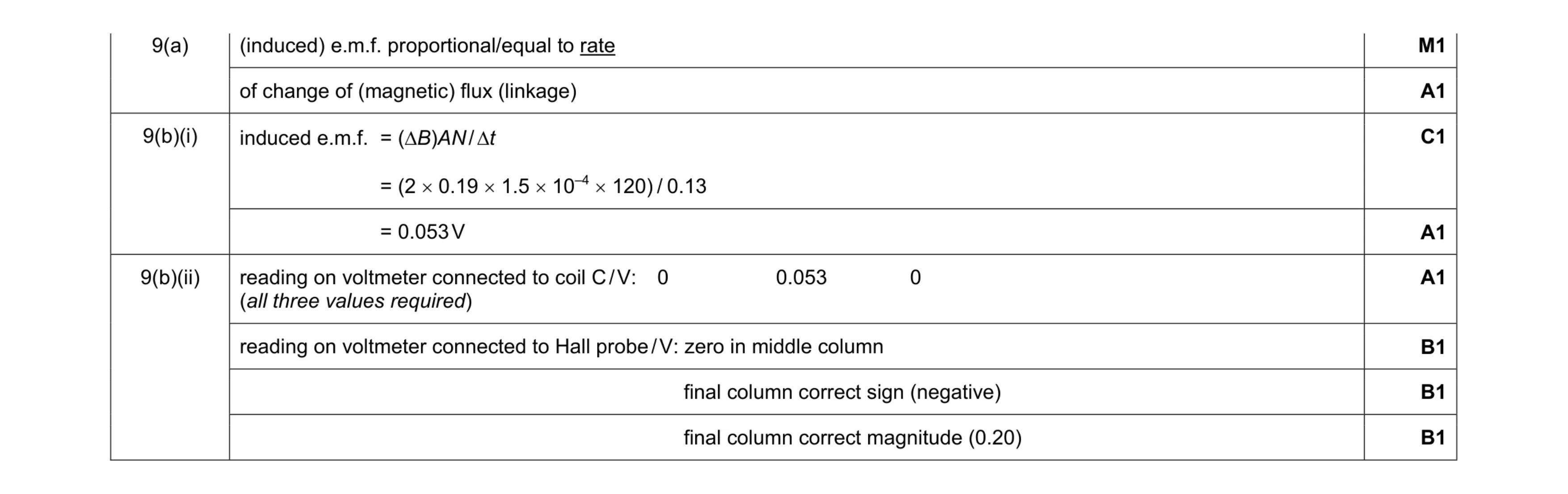 8
8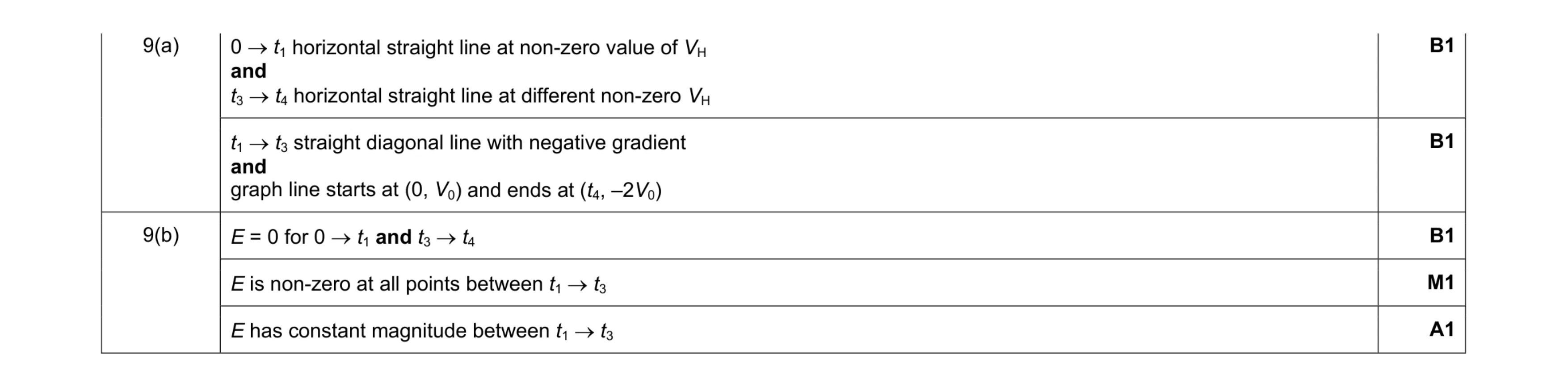 5
5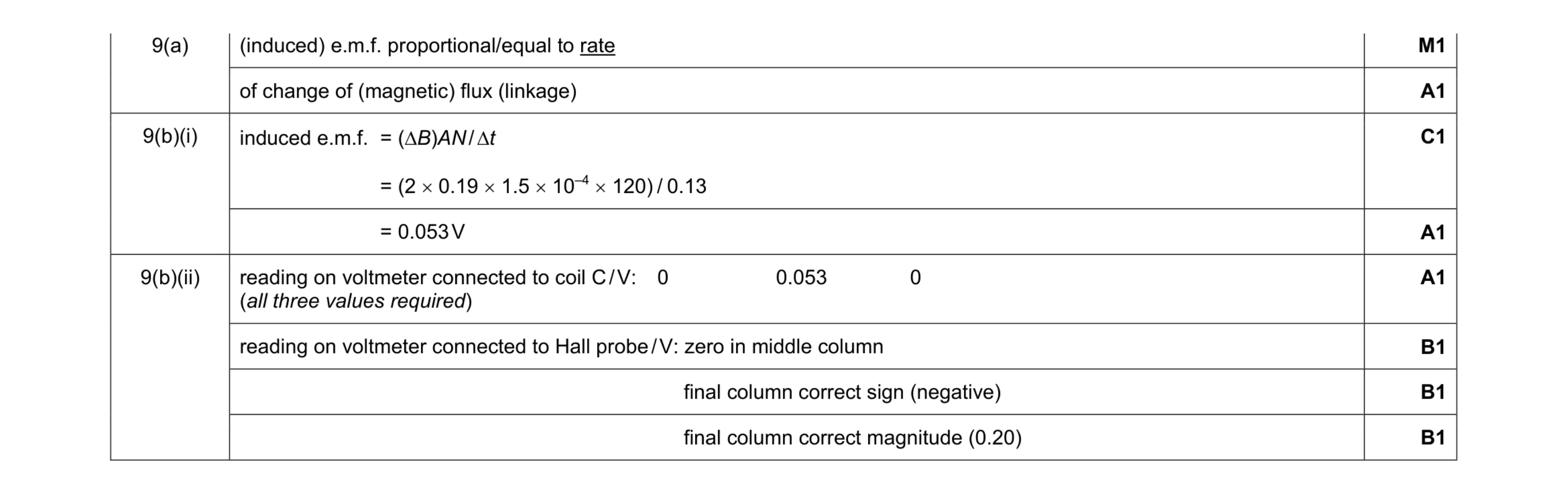 8
8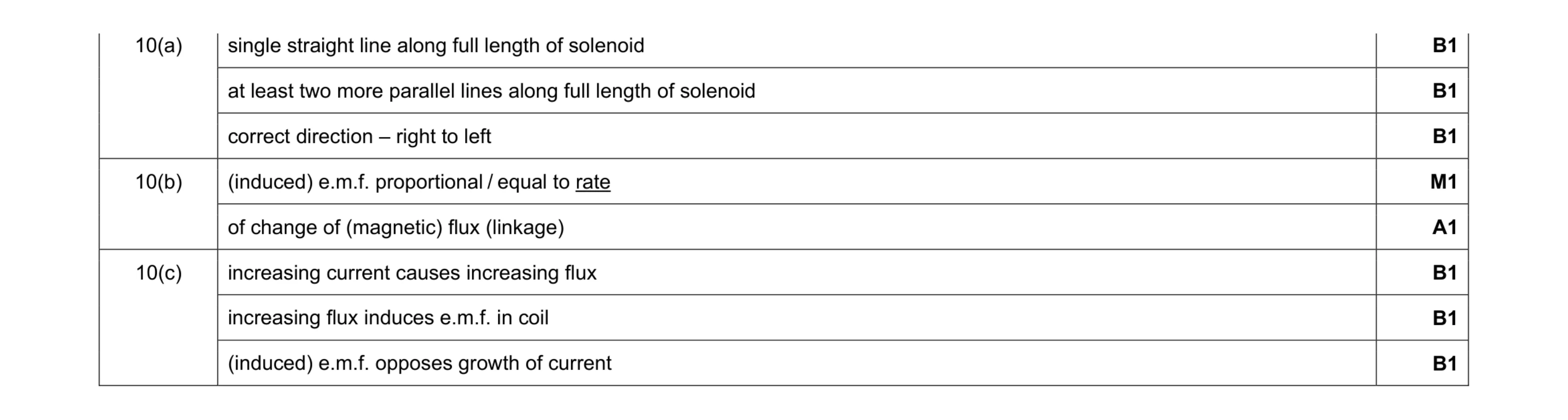 8
8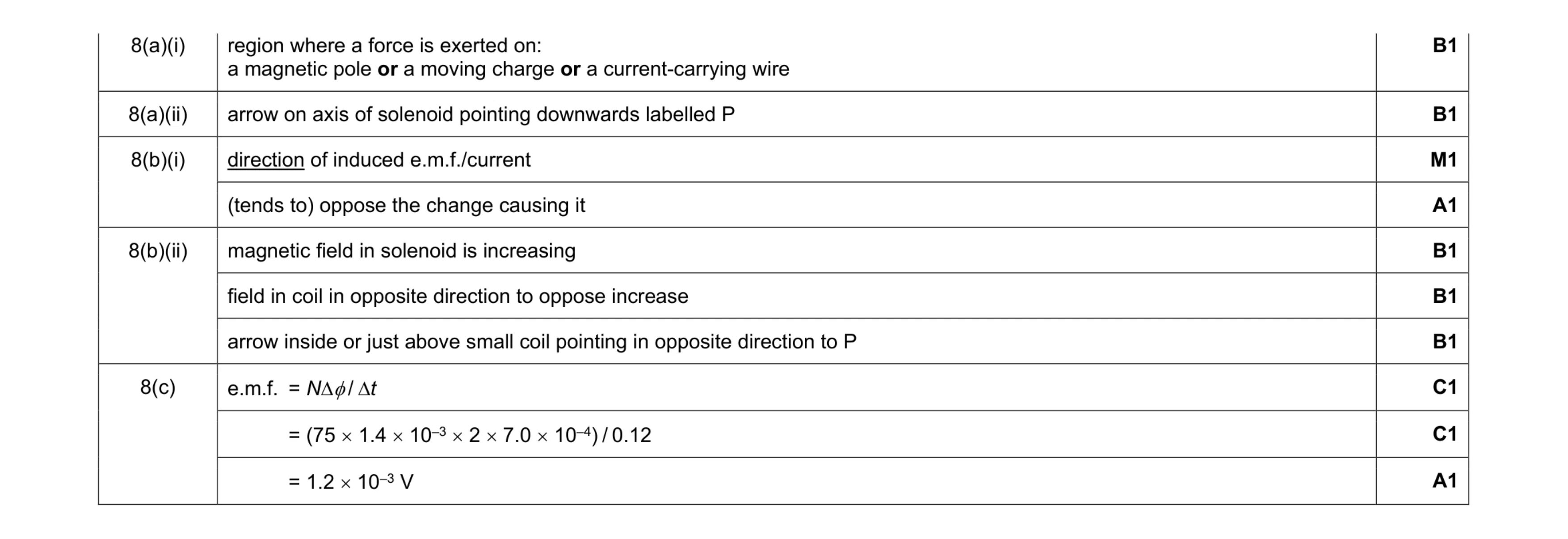 10
10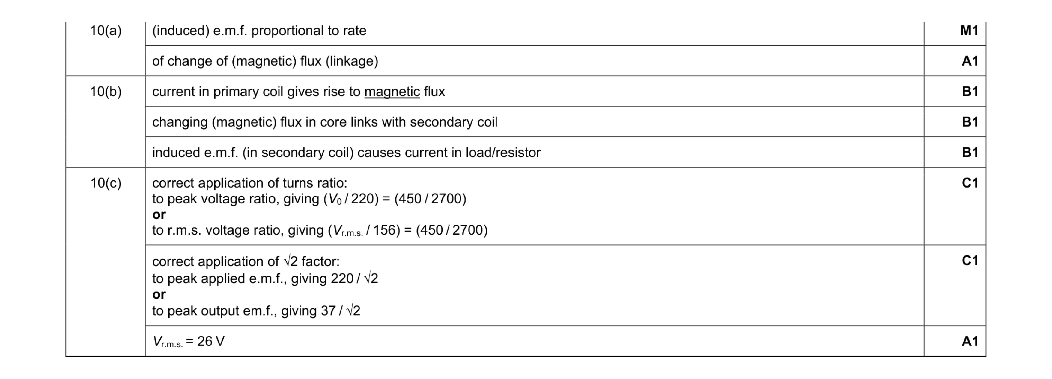 8
8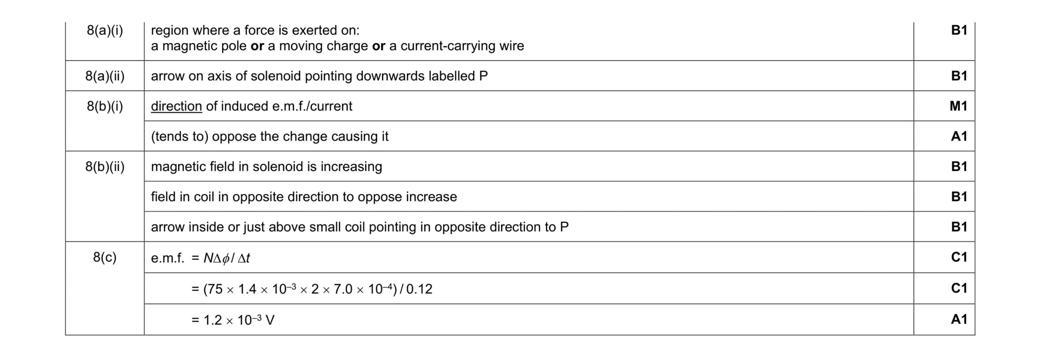 10
10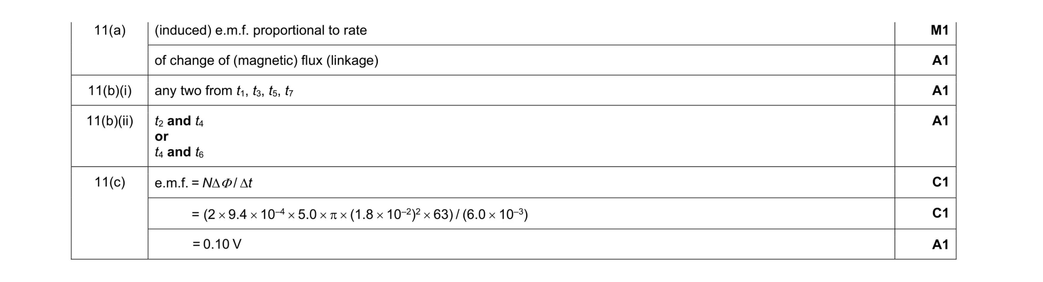 7
7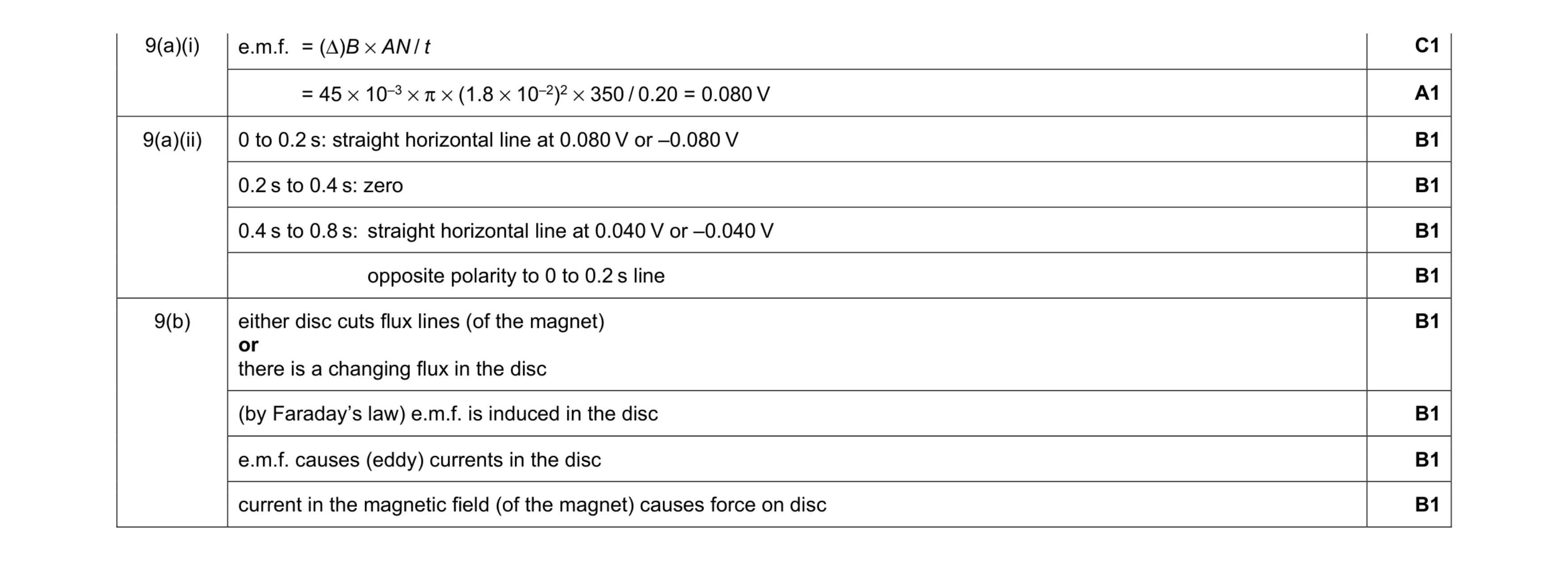 10
10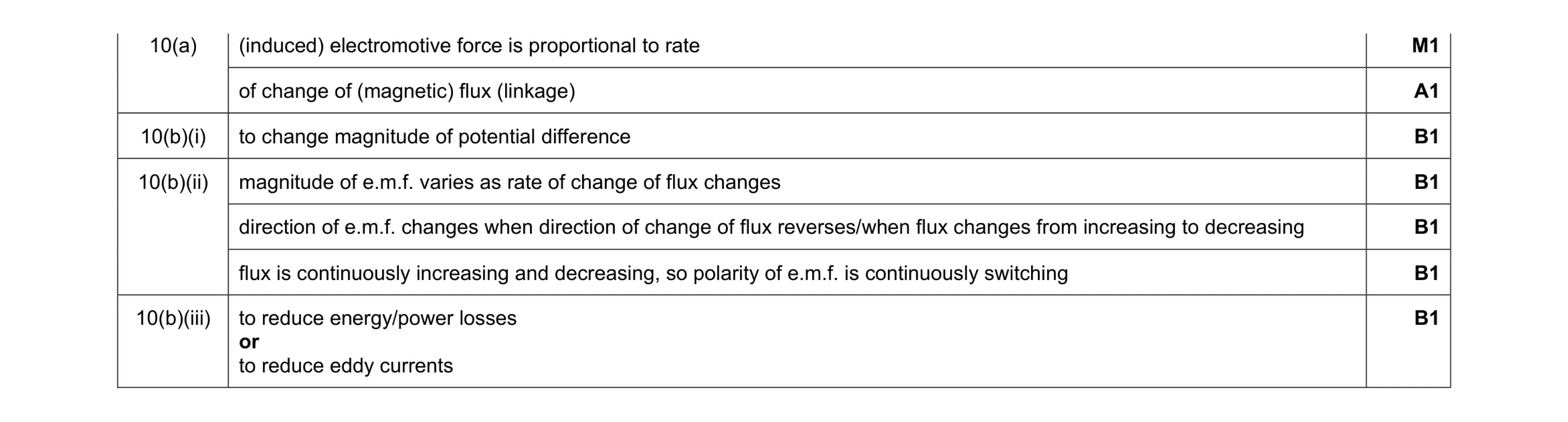 7
7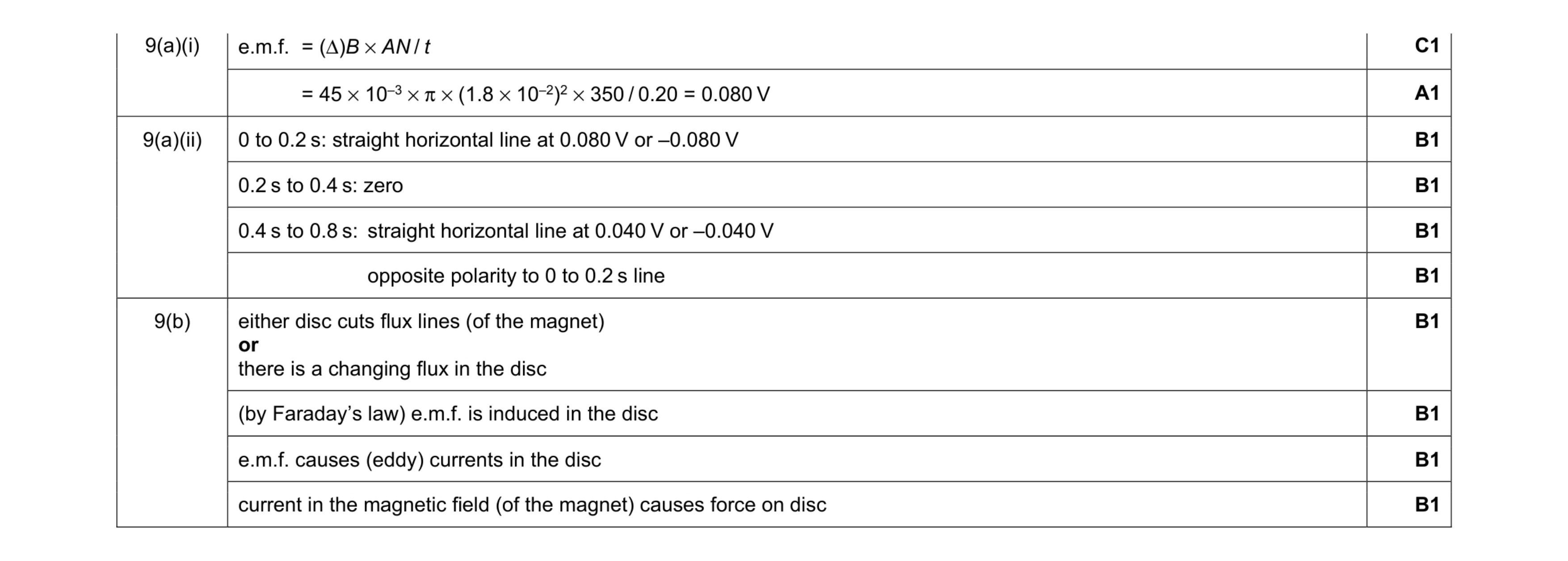 10
10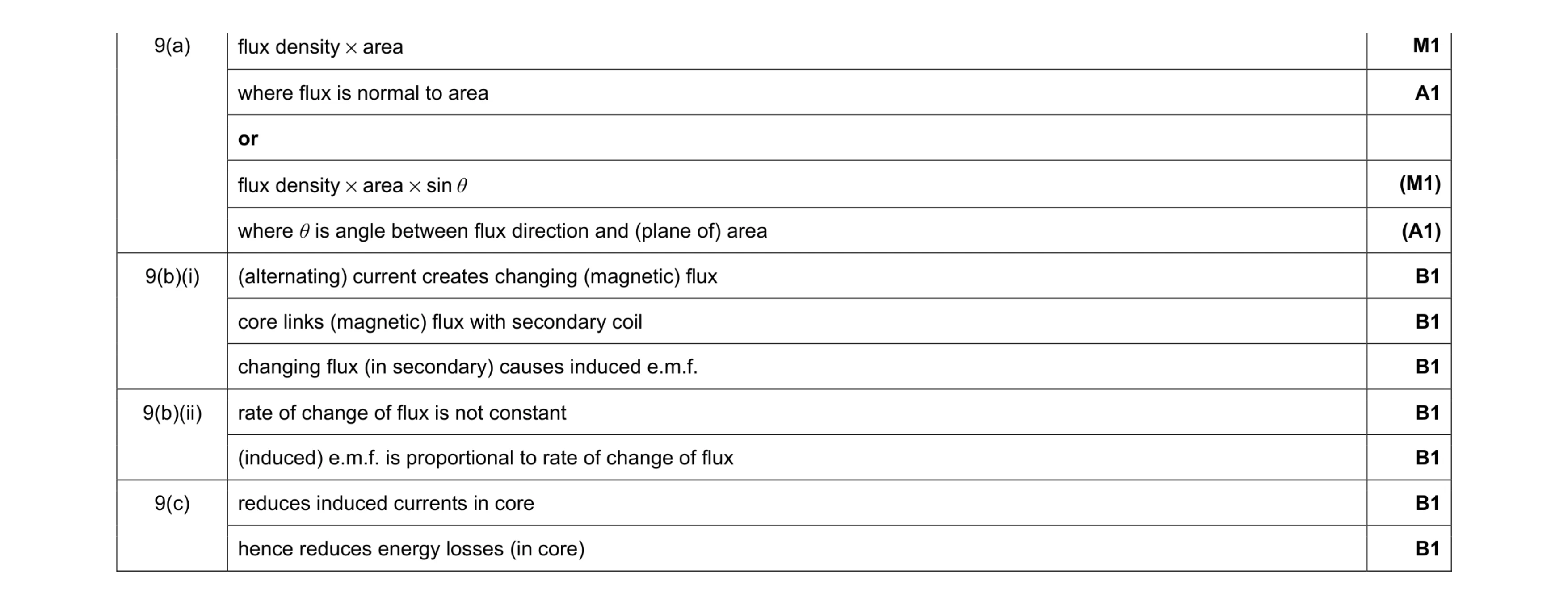 9
9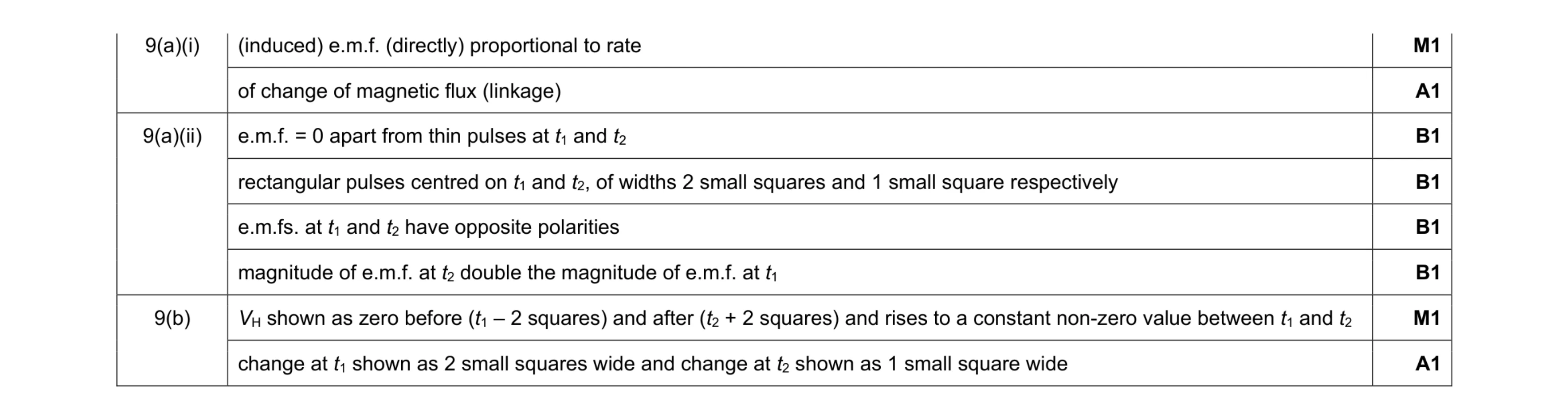 8
8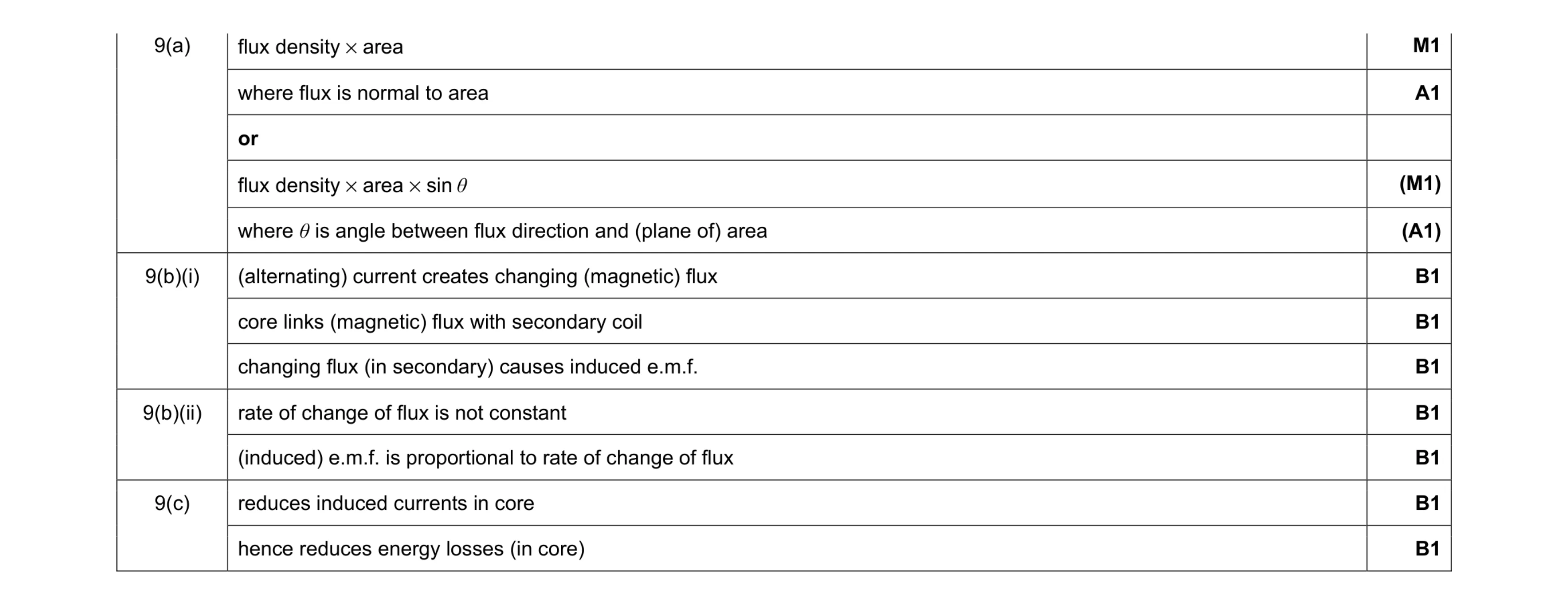 9
9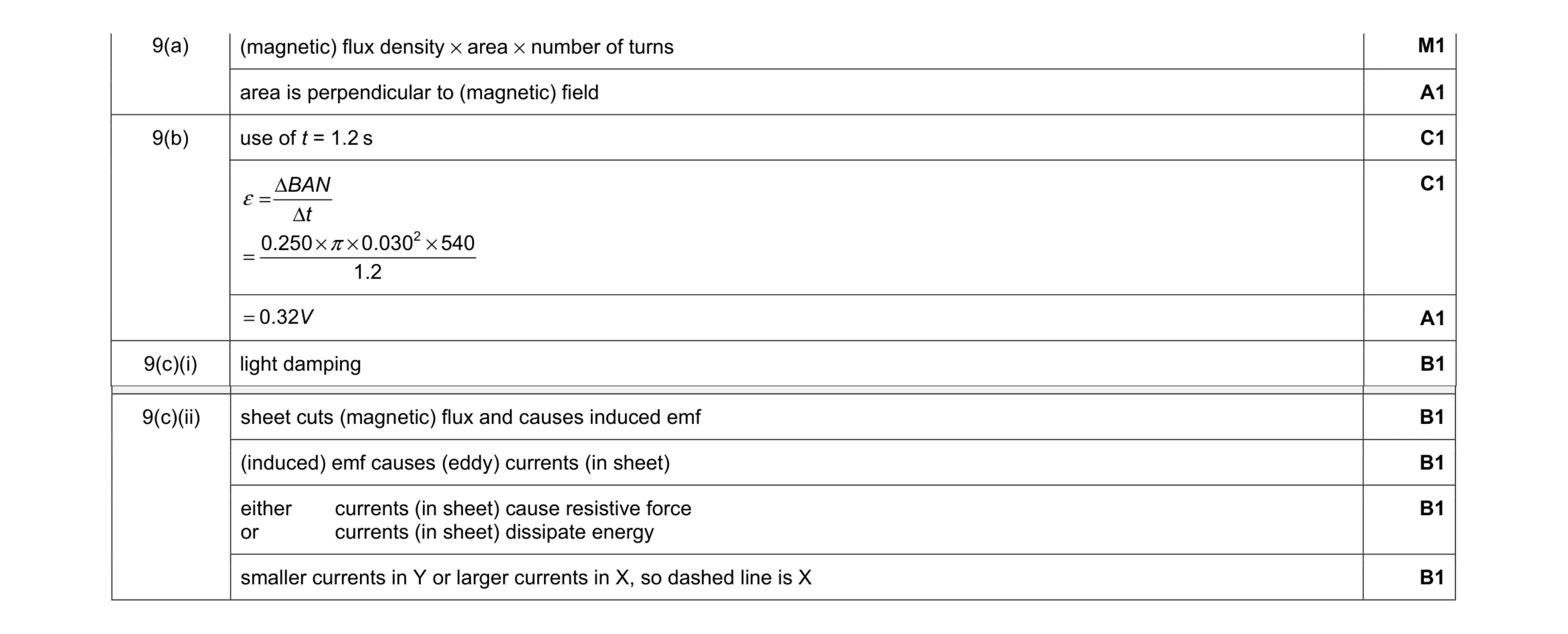 10
10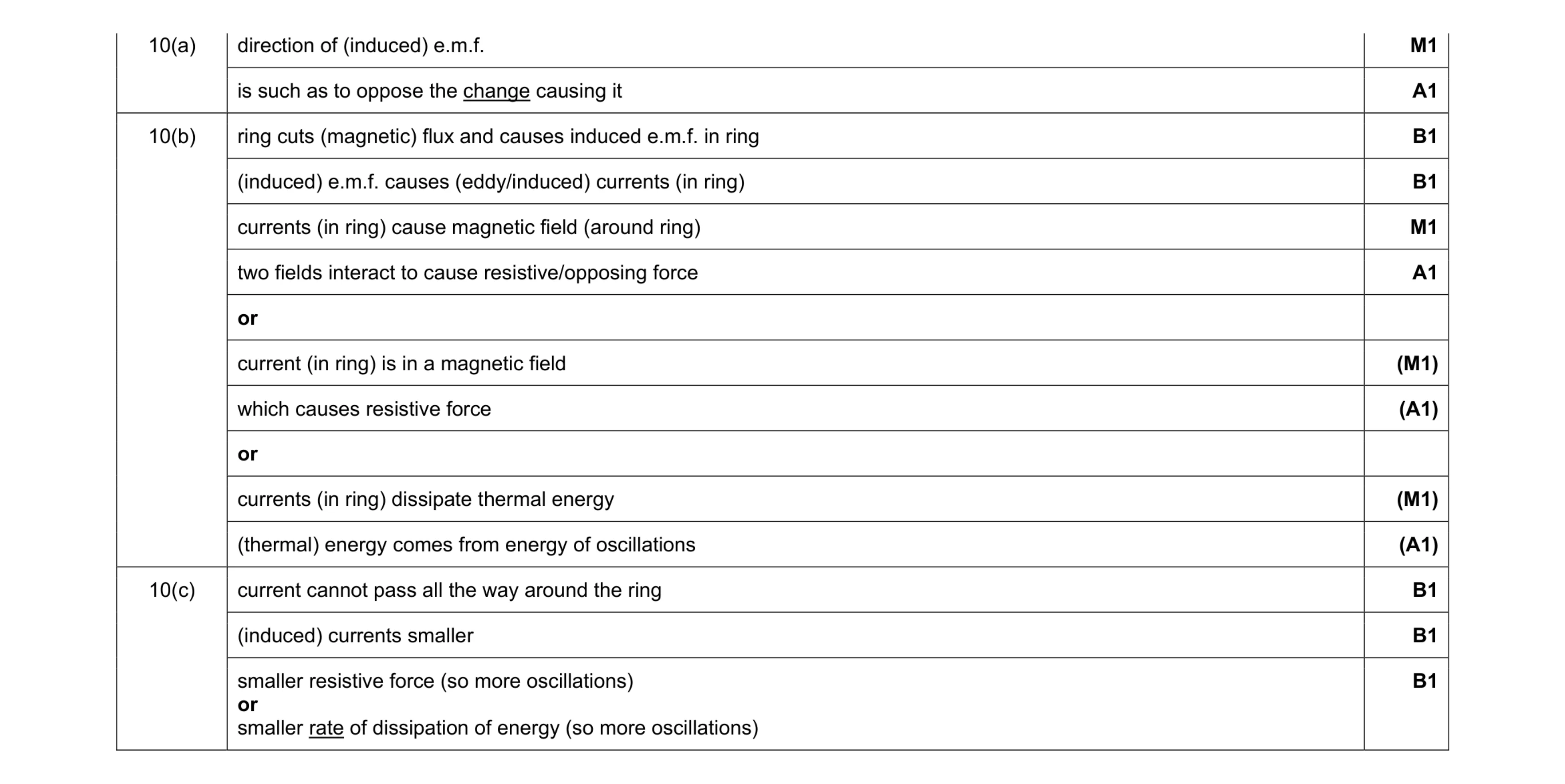 9
9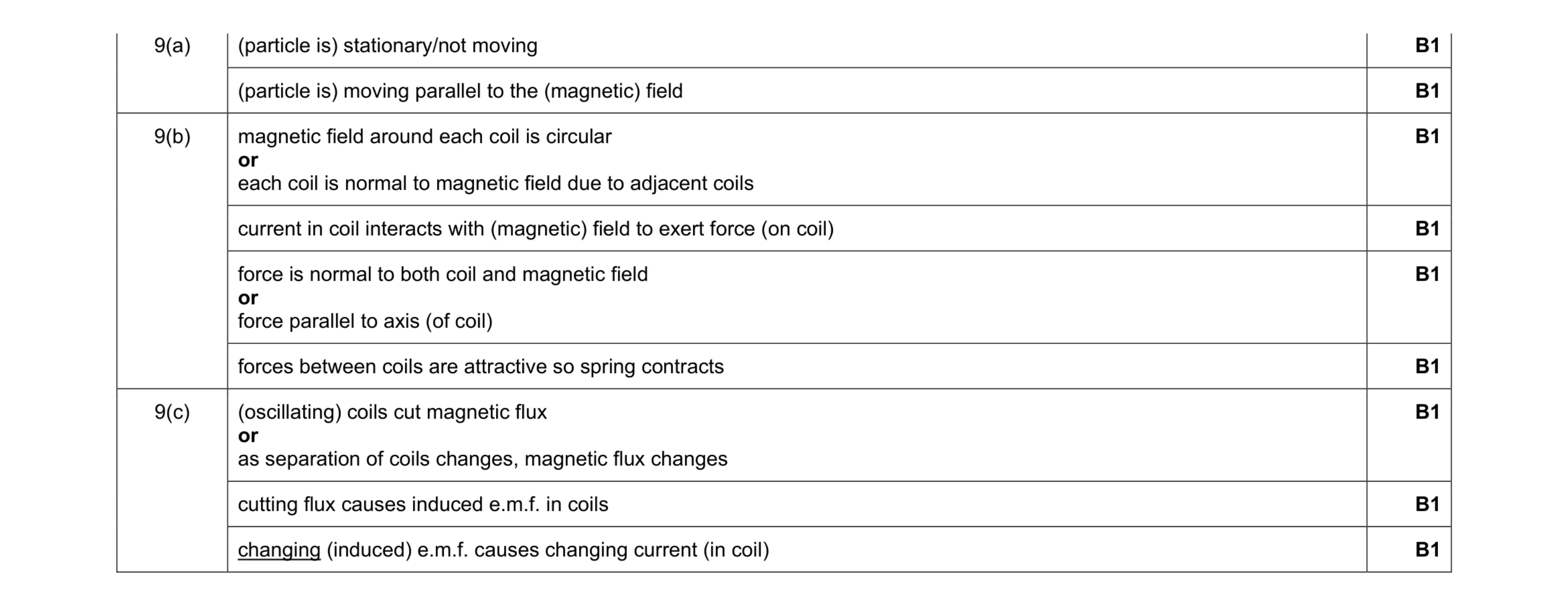 9
9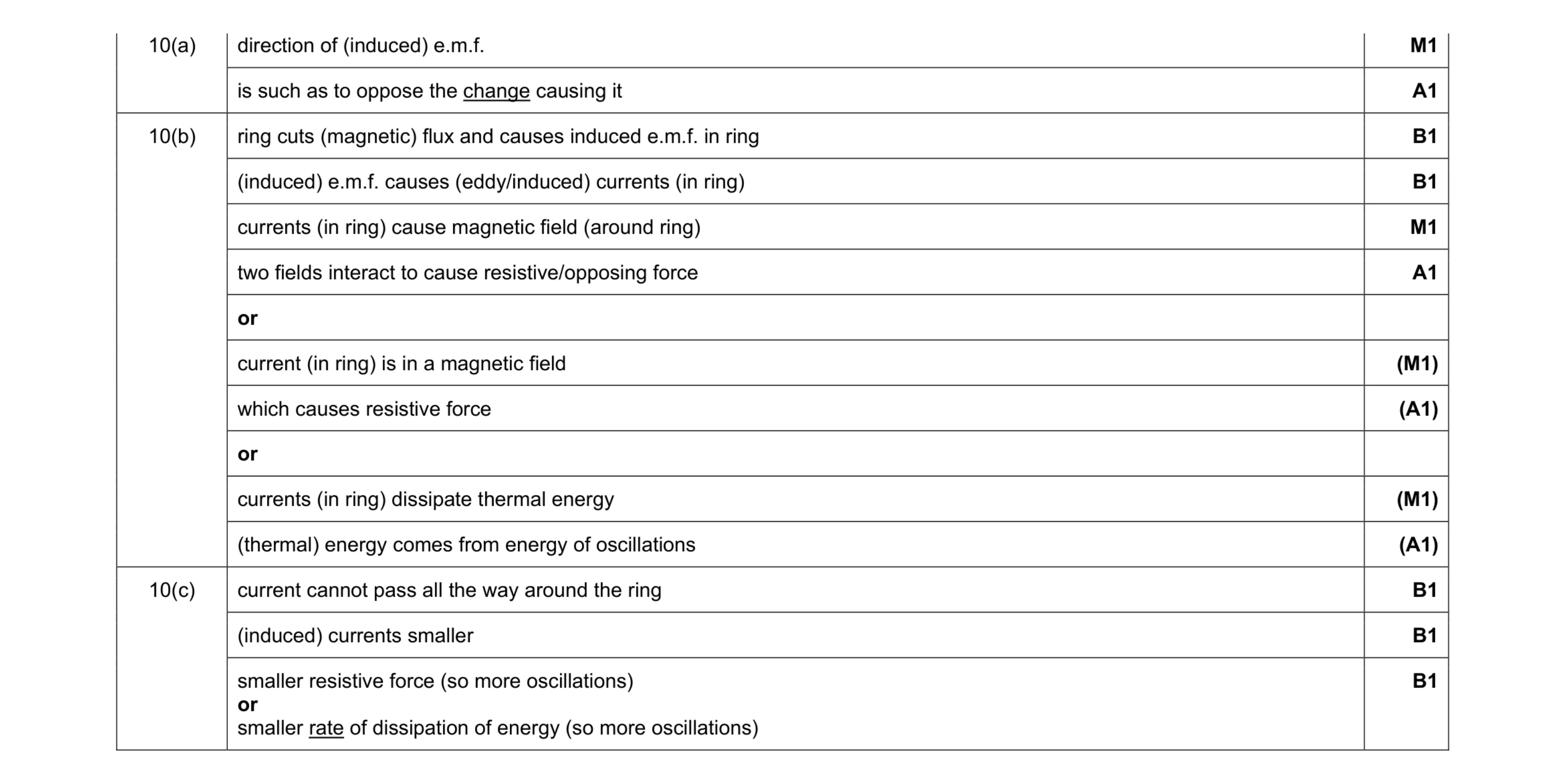 9
9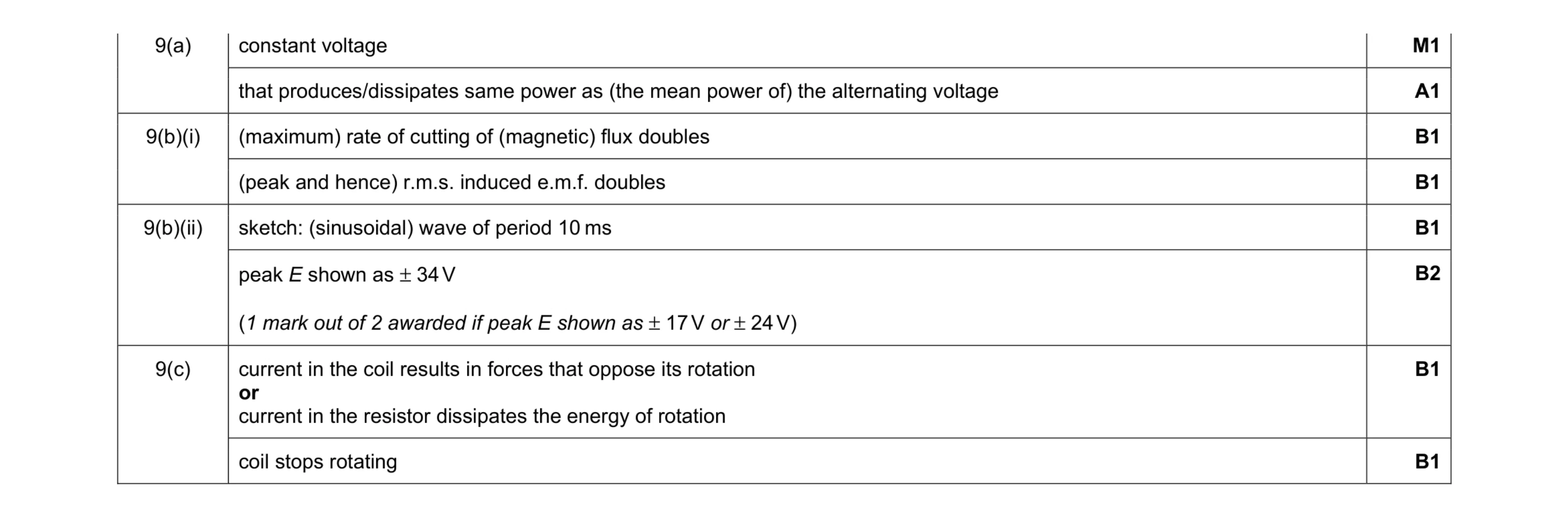 9
9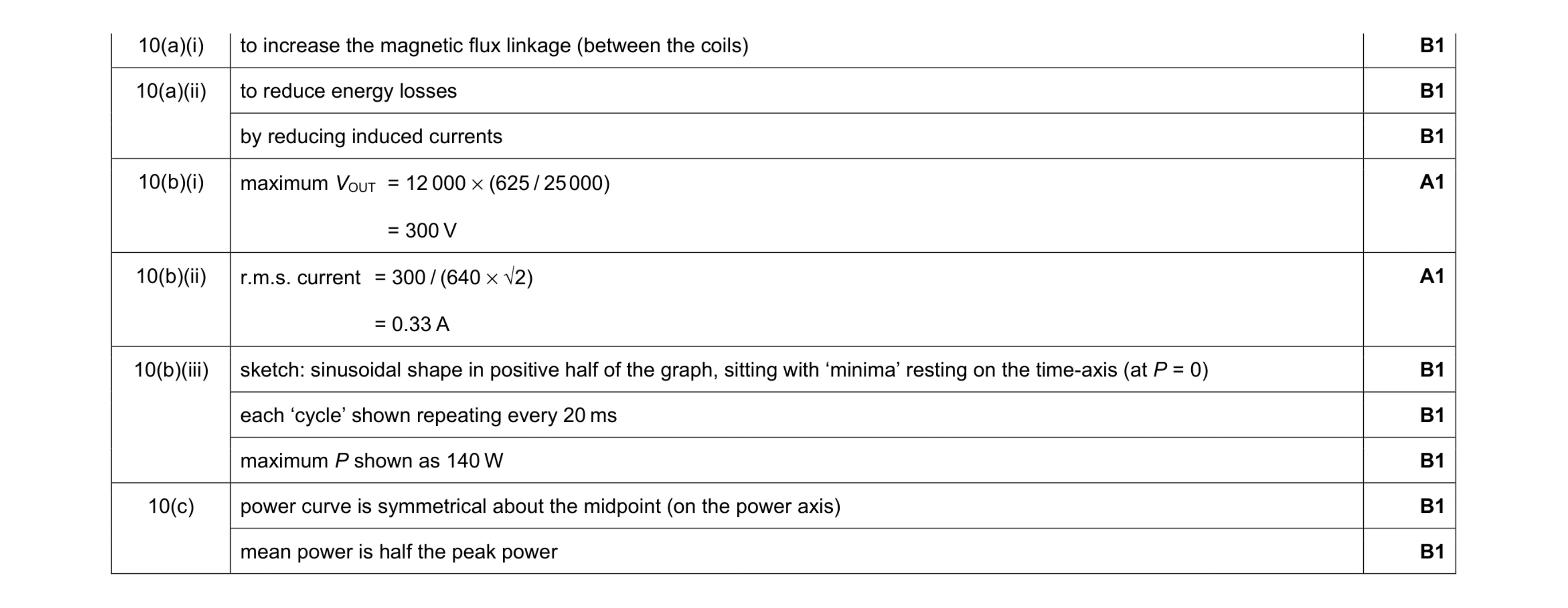 10
10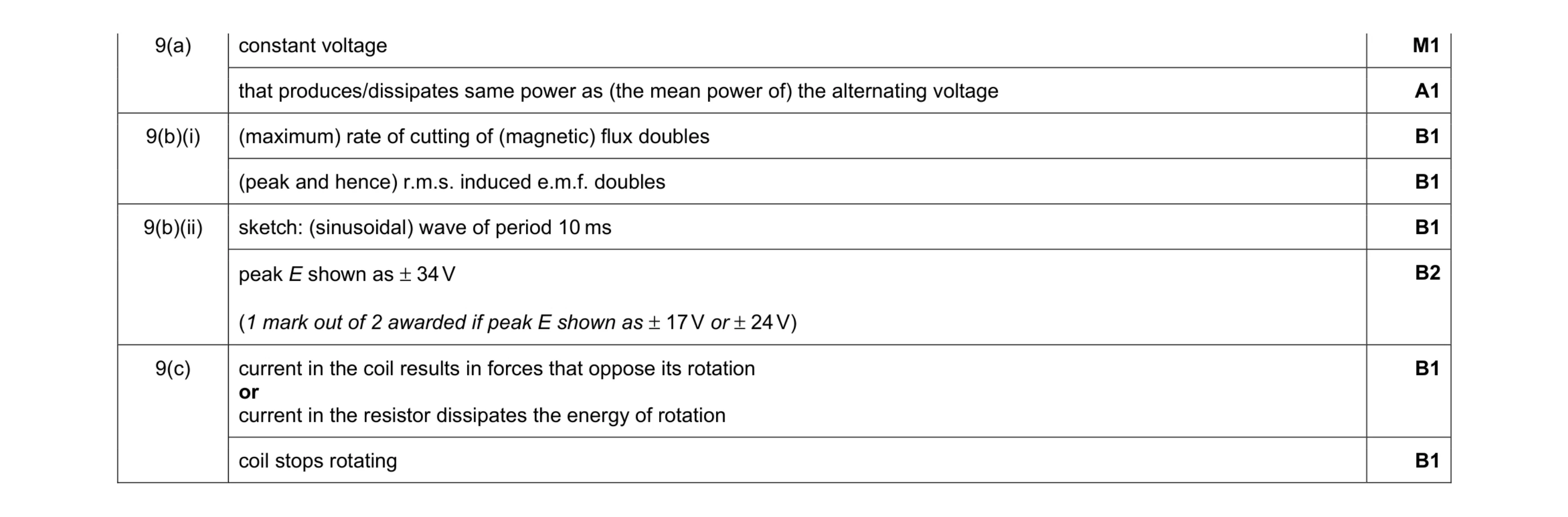 9
9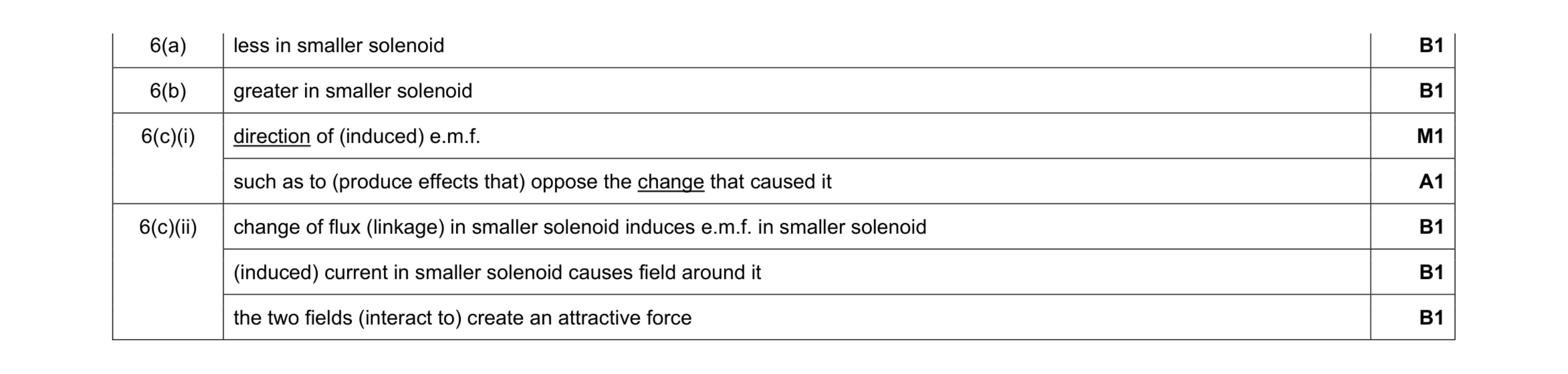 7
7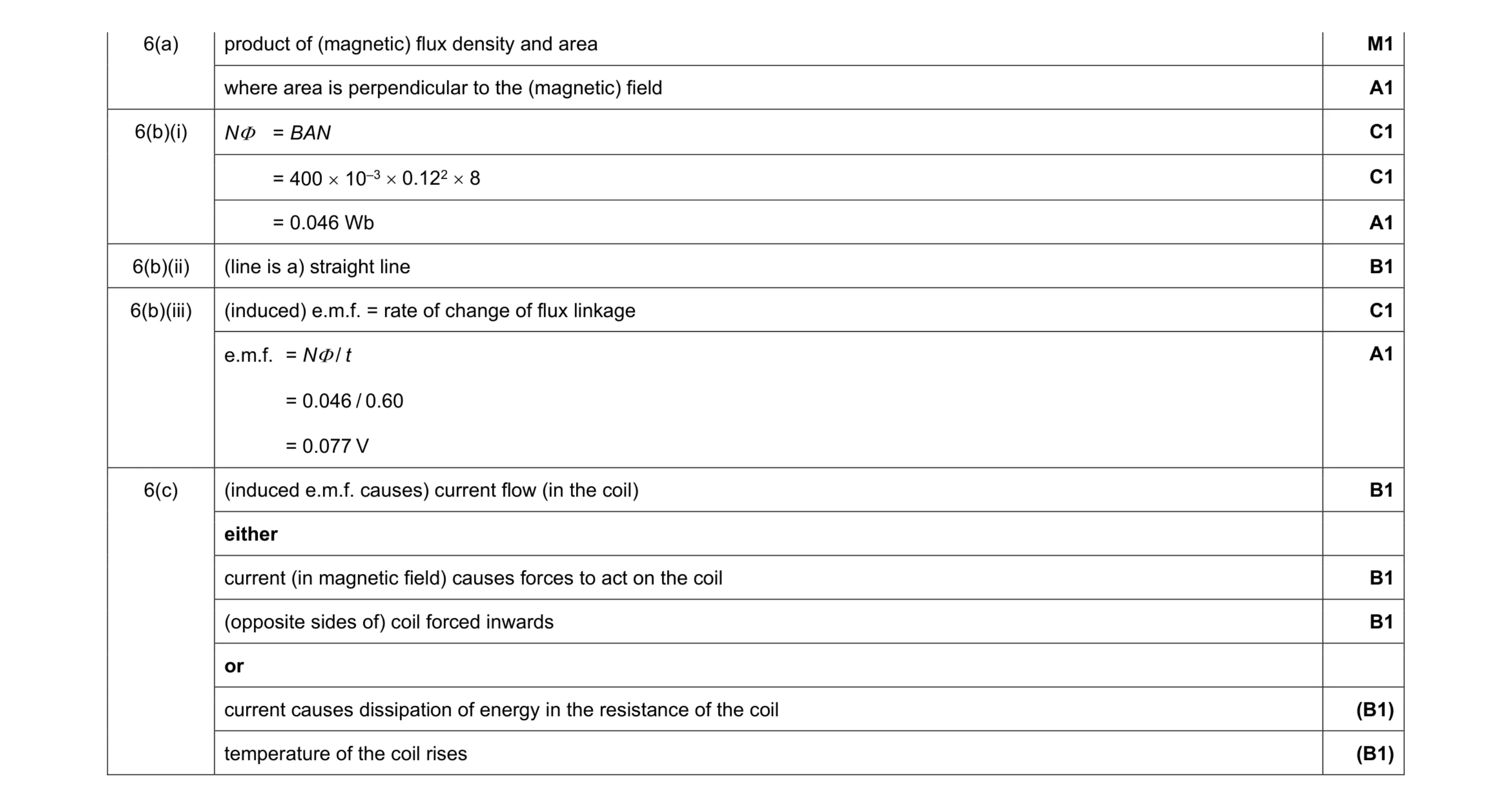 11
11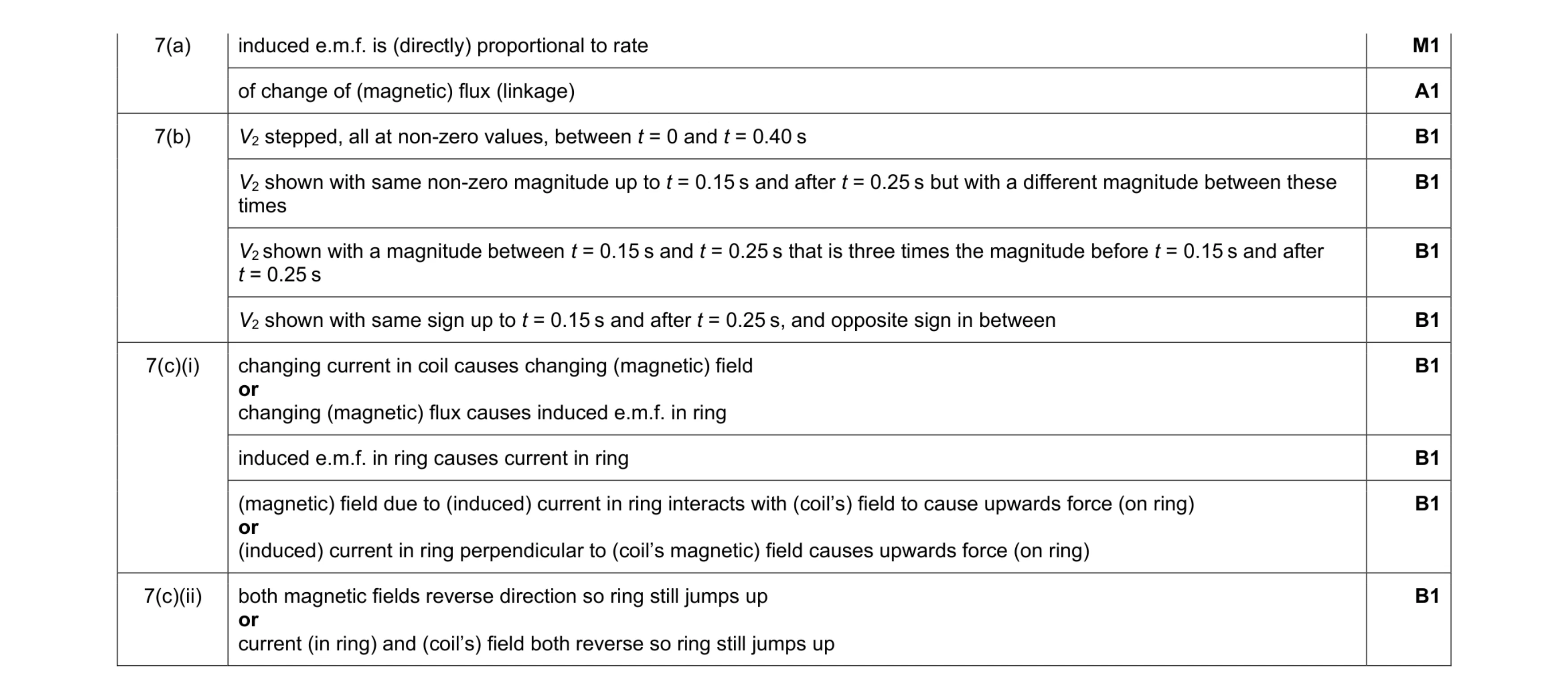 10
10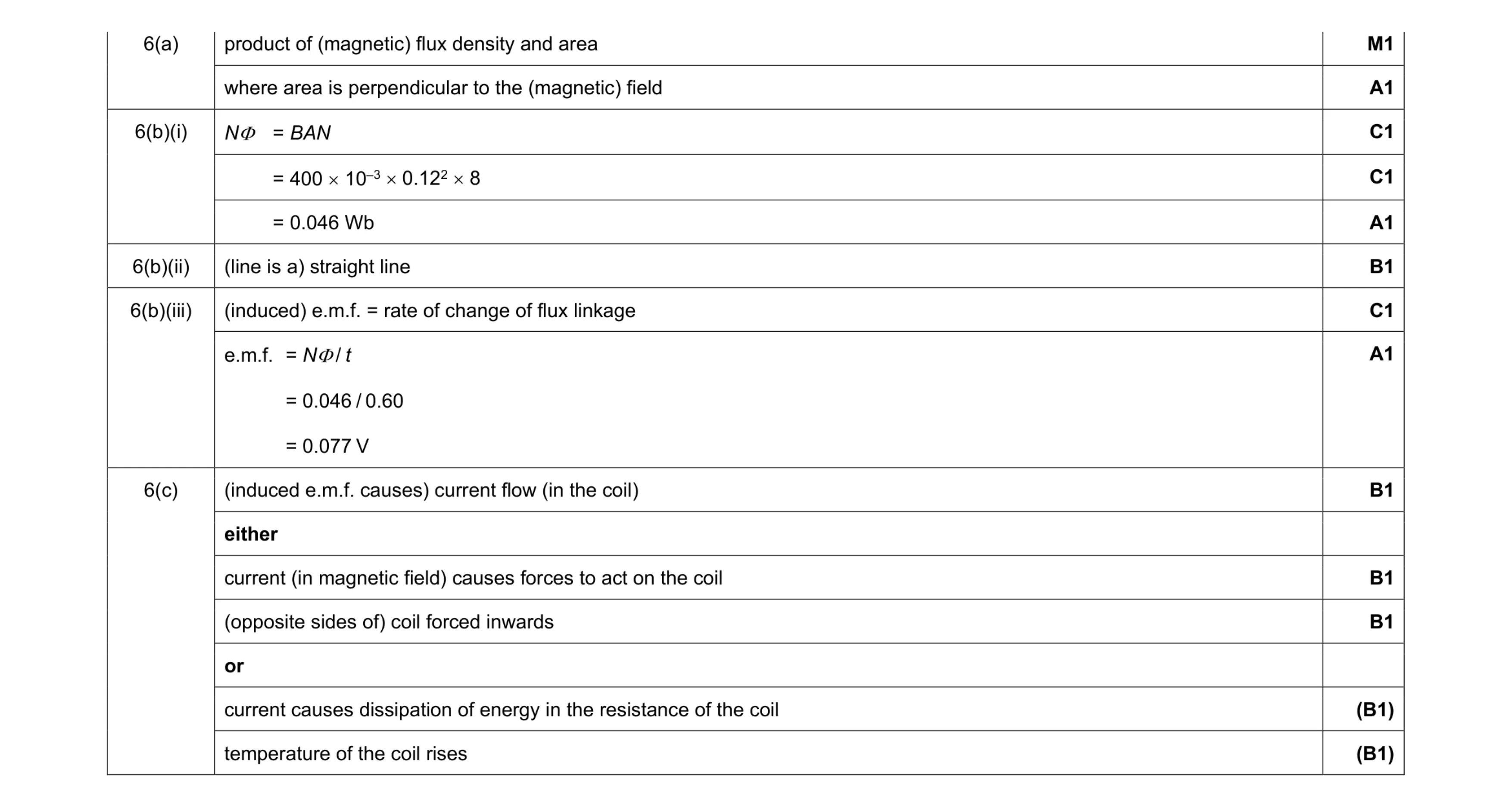 11
11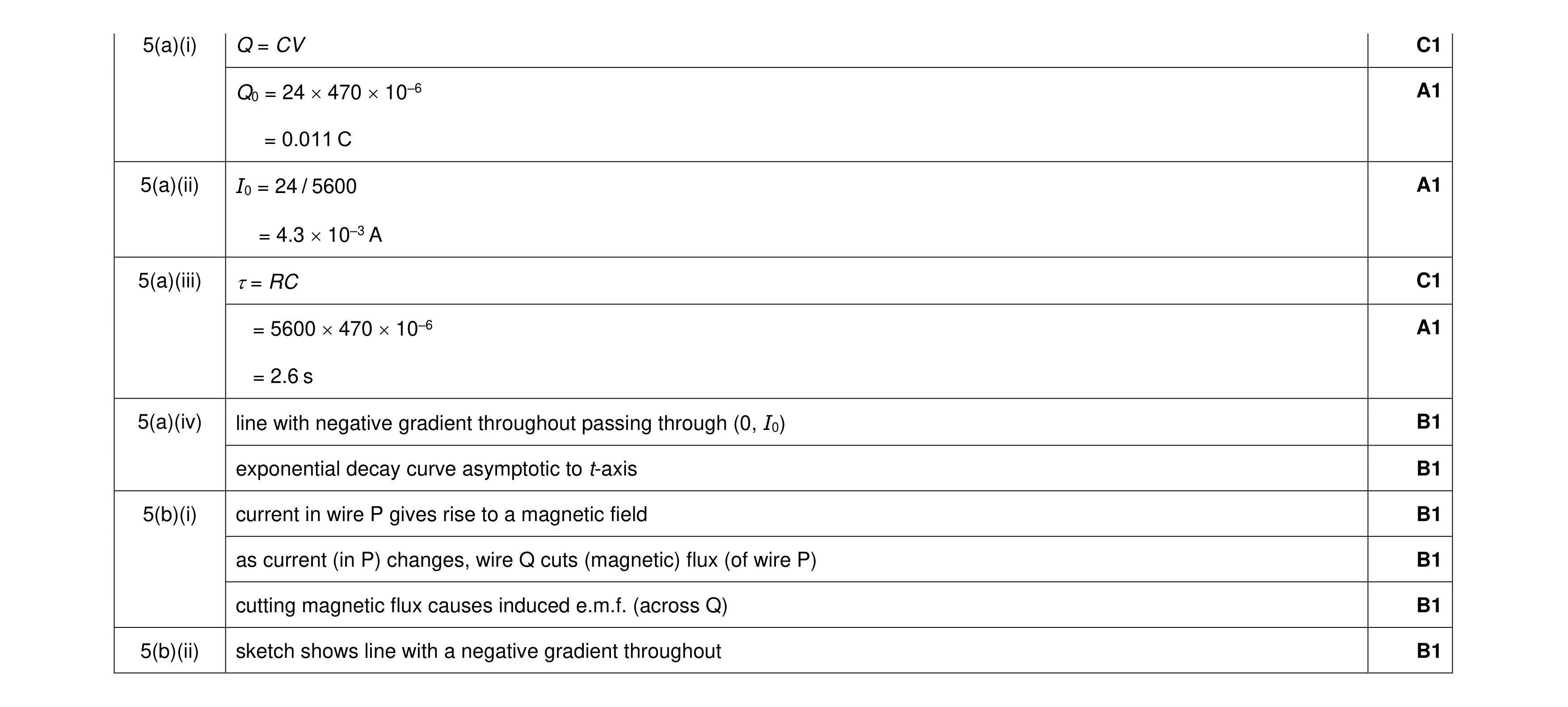 11
11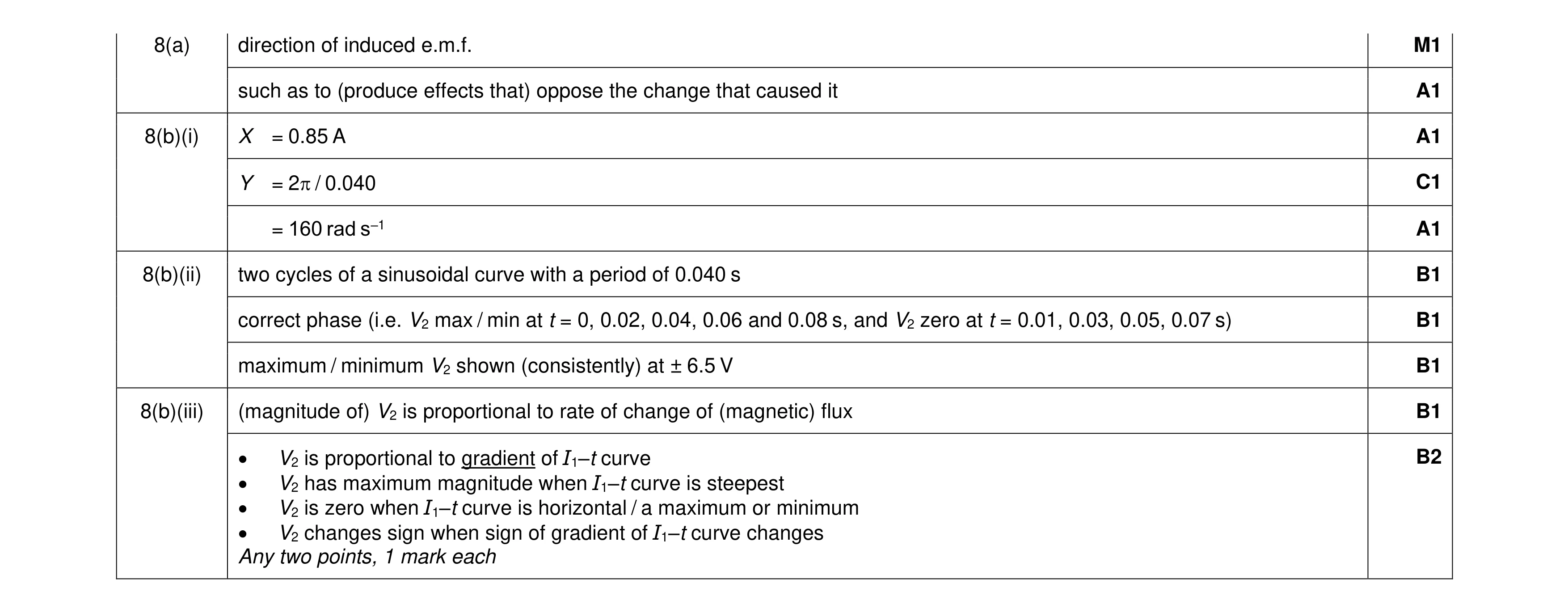 11
11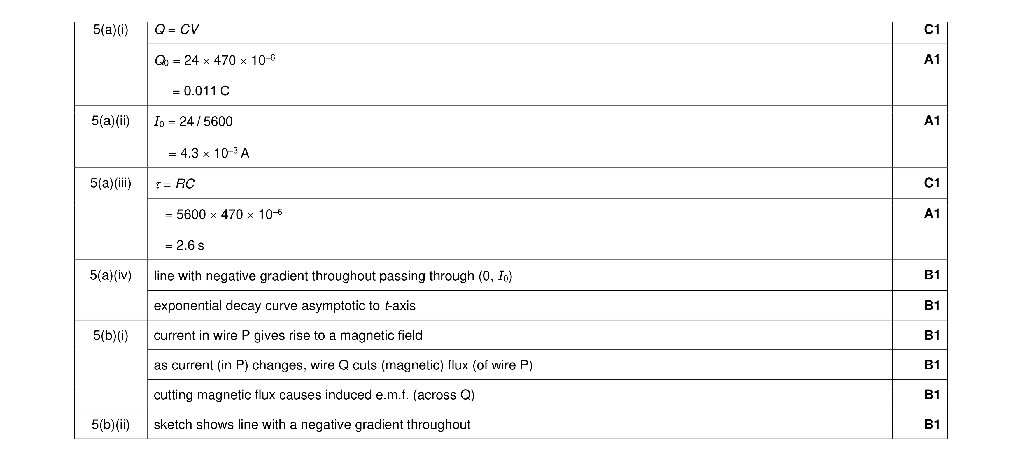 11
11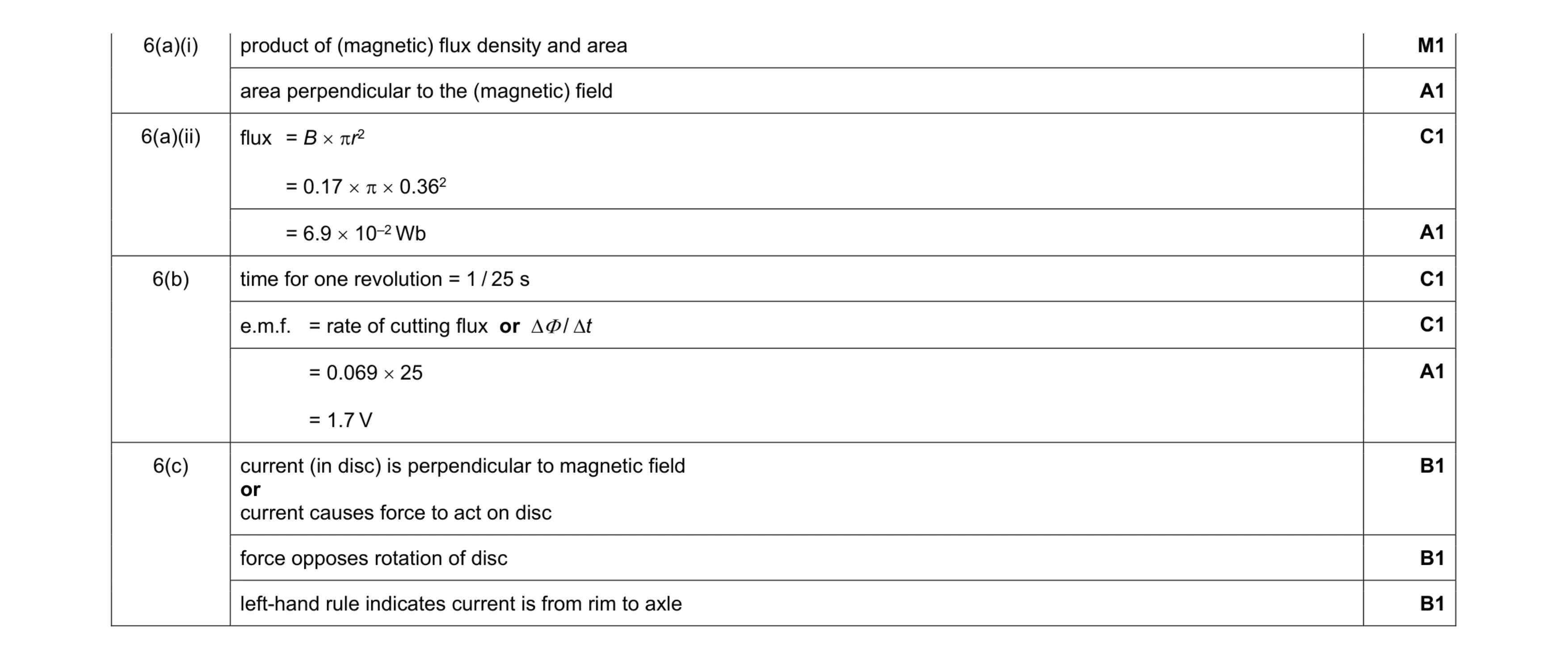 10
10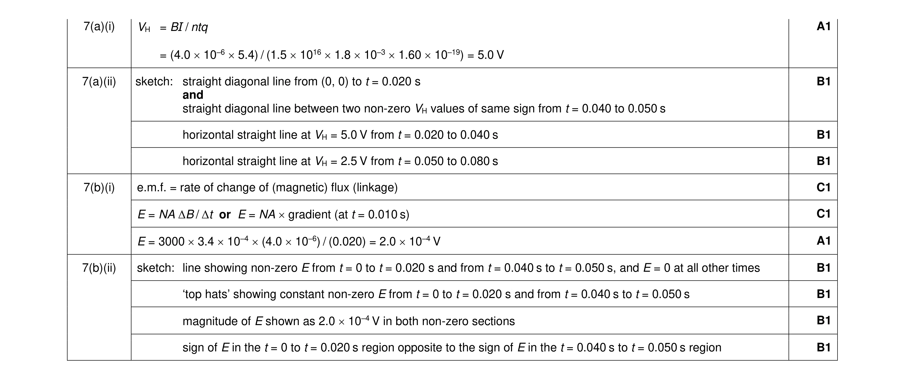 11
11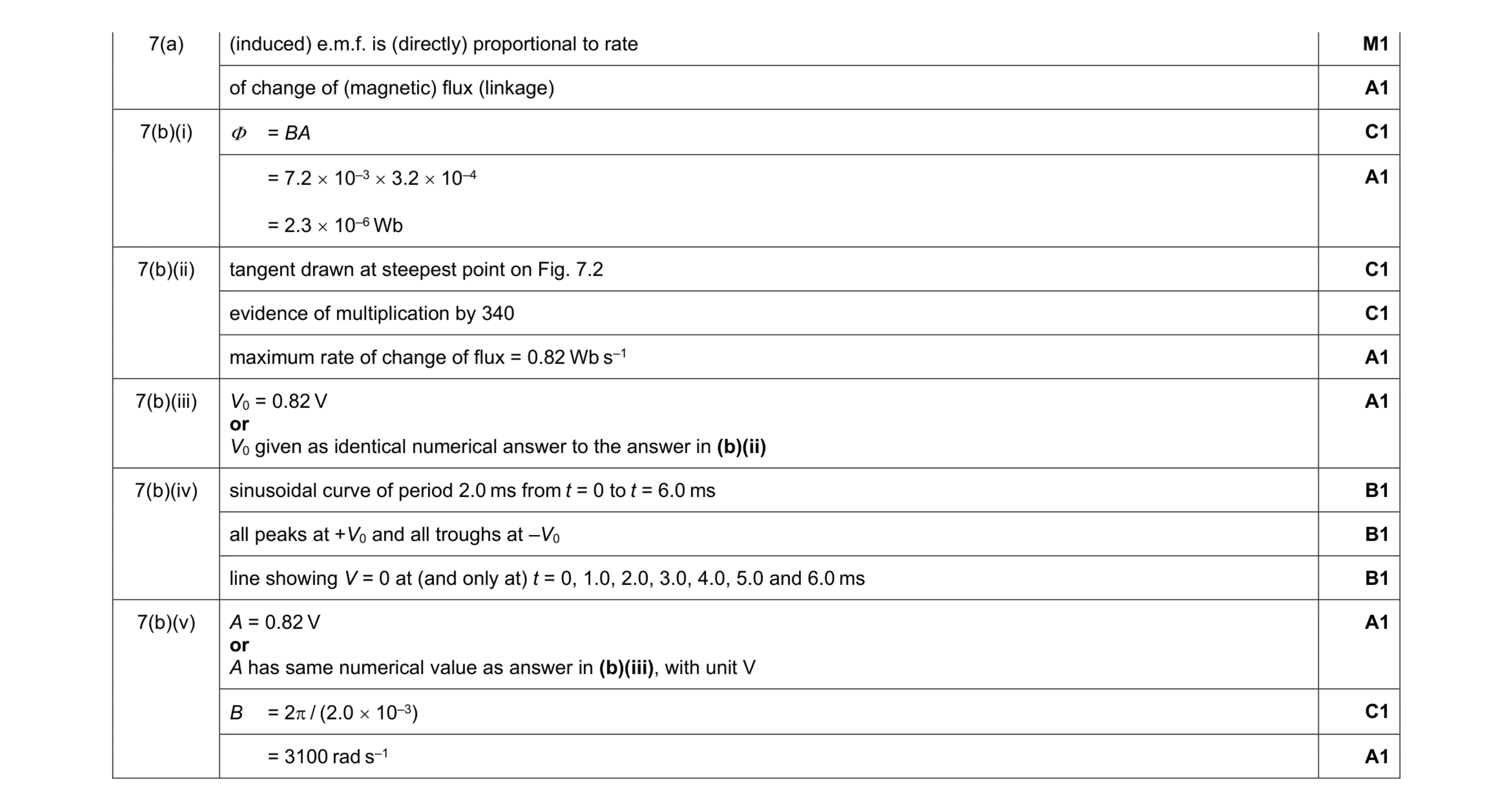 14
14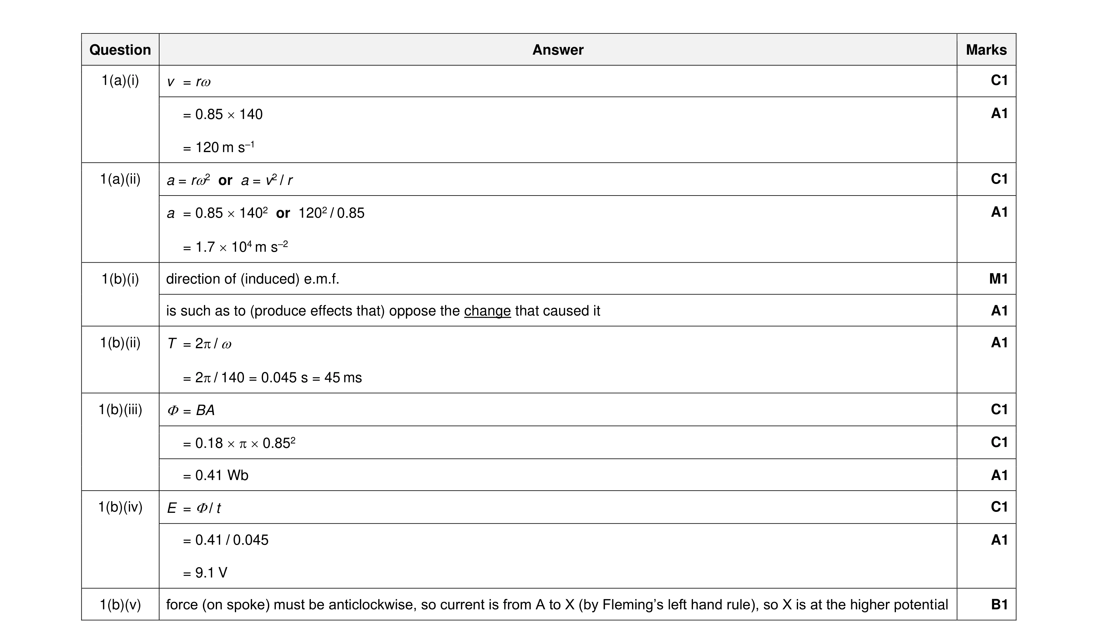 13
13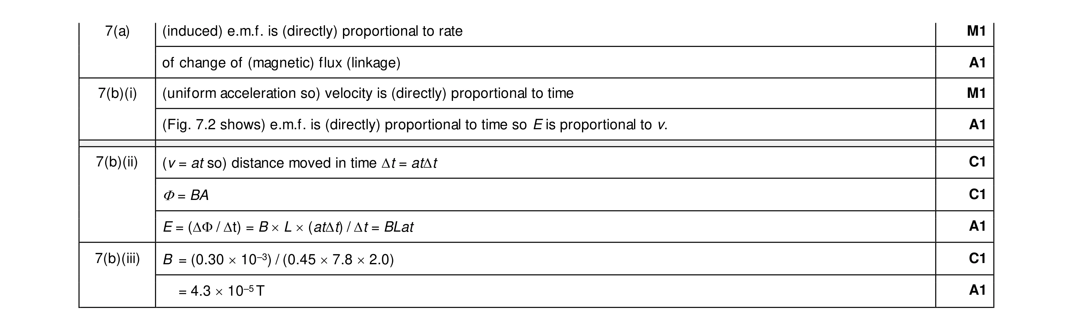 9
9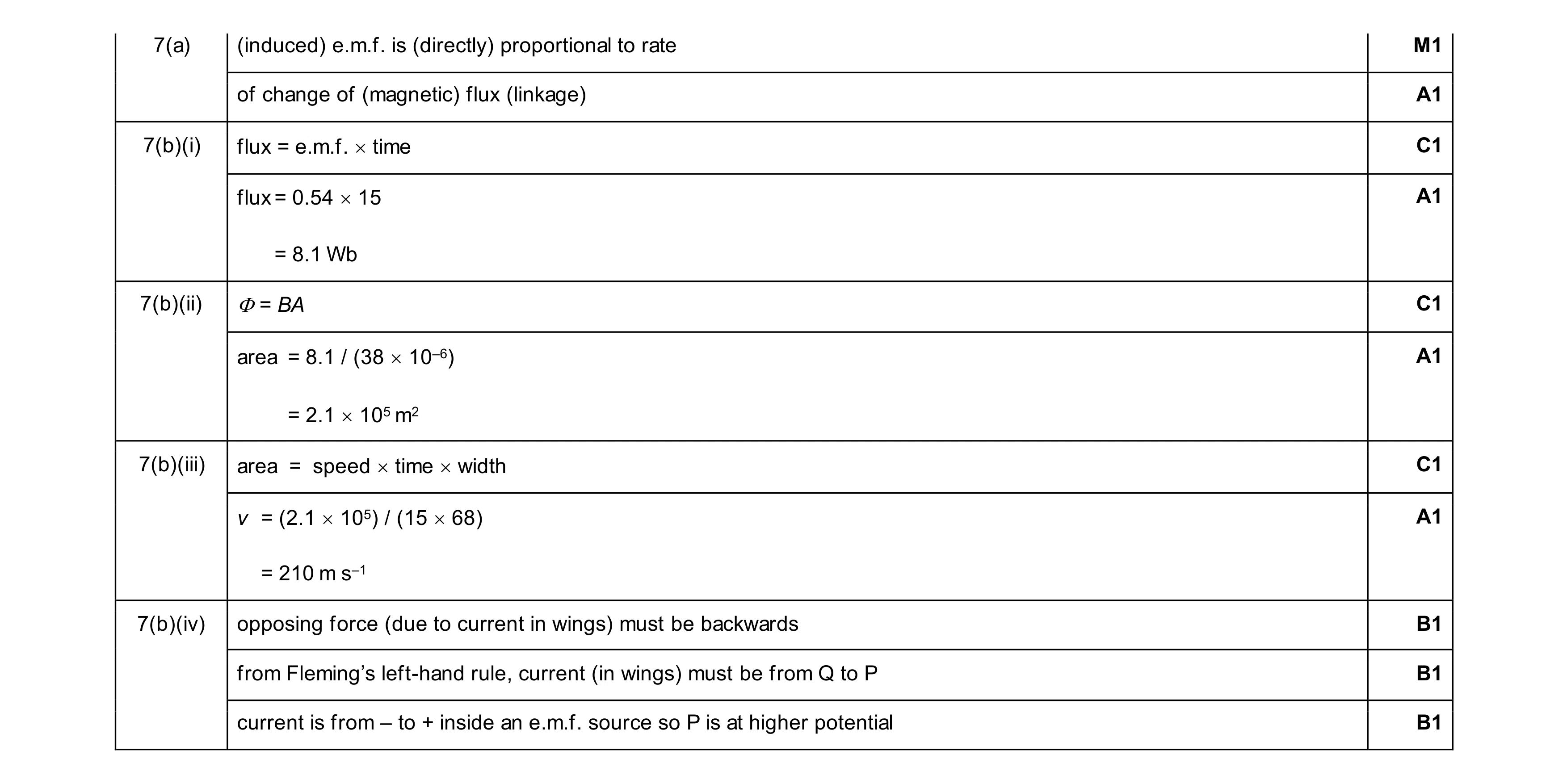 11
11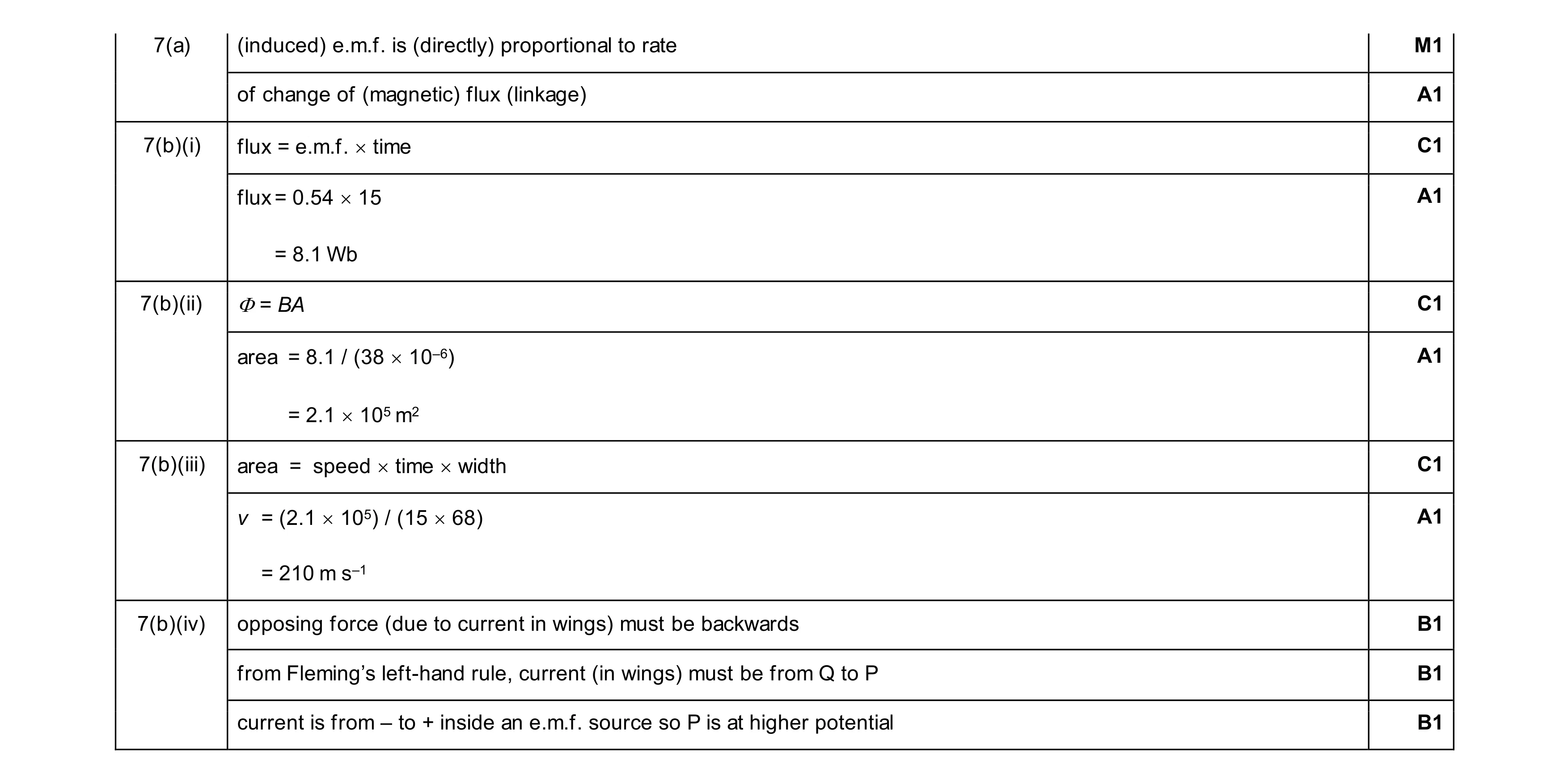 11
11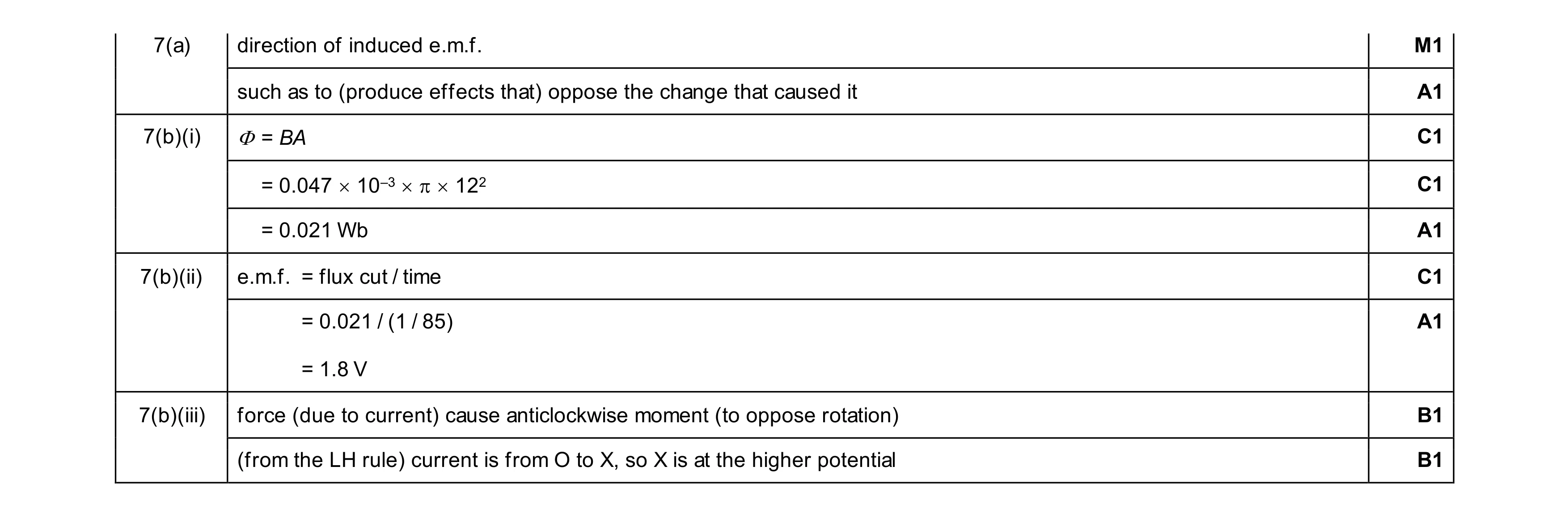 9
9