Cambridge A Level Physics 9702 — 2019 Oct/Nov Paper 4 · Variant 2
9702/42/O/N/19 · 12 questions · 100 marks · ≈113 min
The question paper and its mark scheme, free to read here and free to download. This is Cambridge’s own paper, exactly as it was sat.
Question paper28 pages
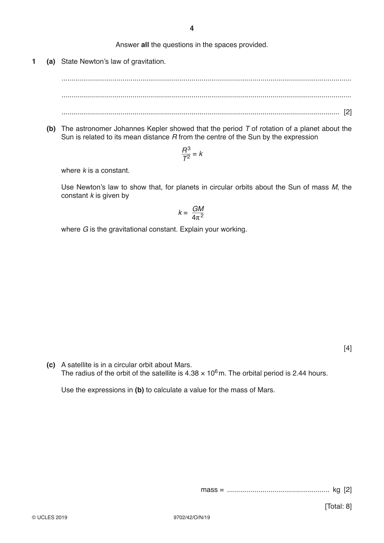

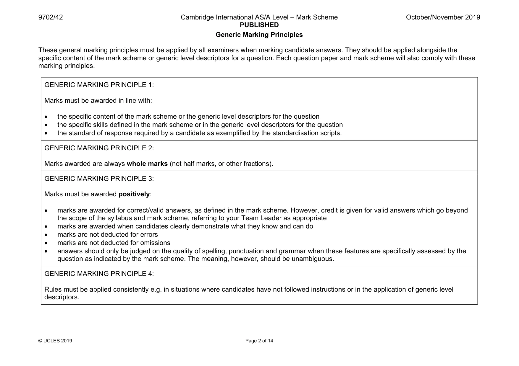
Mark scheme14 pages
Answers below. Sit the paper first if you are practising.
Questions as text
Q1 · State Newton’s law of gravitation
1 (a) State Newton’s law of gravitation. ................................................................................................................................................... ................................................................................................................................................... ............................................................................................................................................. [2] (b) The astronomer Johannes Kepler showed that the period T of rotation of a planet about the Sun is related to its mean distance R from the centre of the Sun by the expression R 3 2 = k T where k is a constant. Use Newton’s law to show that, for planets in circular orbits about the Sun of mass M, the constant k is given by GM k = 2 4π where G is the gravitational constant. Explain your working. [4] (c) A satellite is in a circular orbit about Mars. The radius of the orbit of the satellite is 4.38 × 10⁶ m. The orbital period is 2.44 hours. Use the expressions in (b) to calculate a value for the mass of Mars. mass = .................................................... kg [2] [Total: 8]
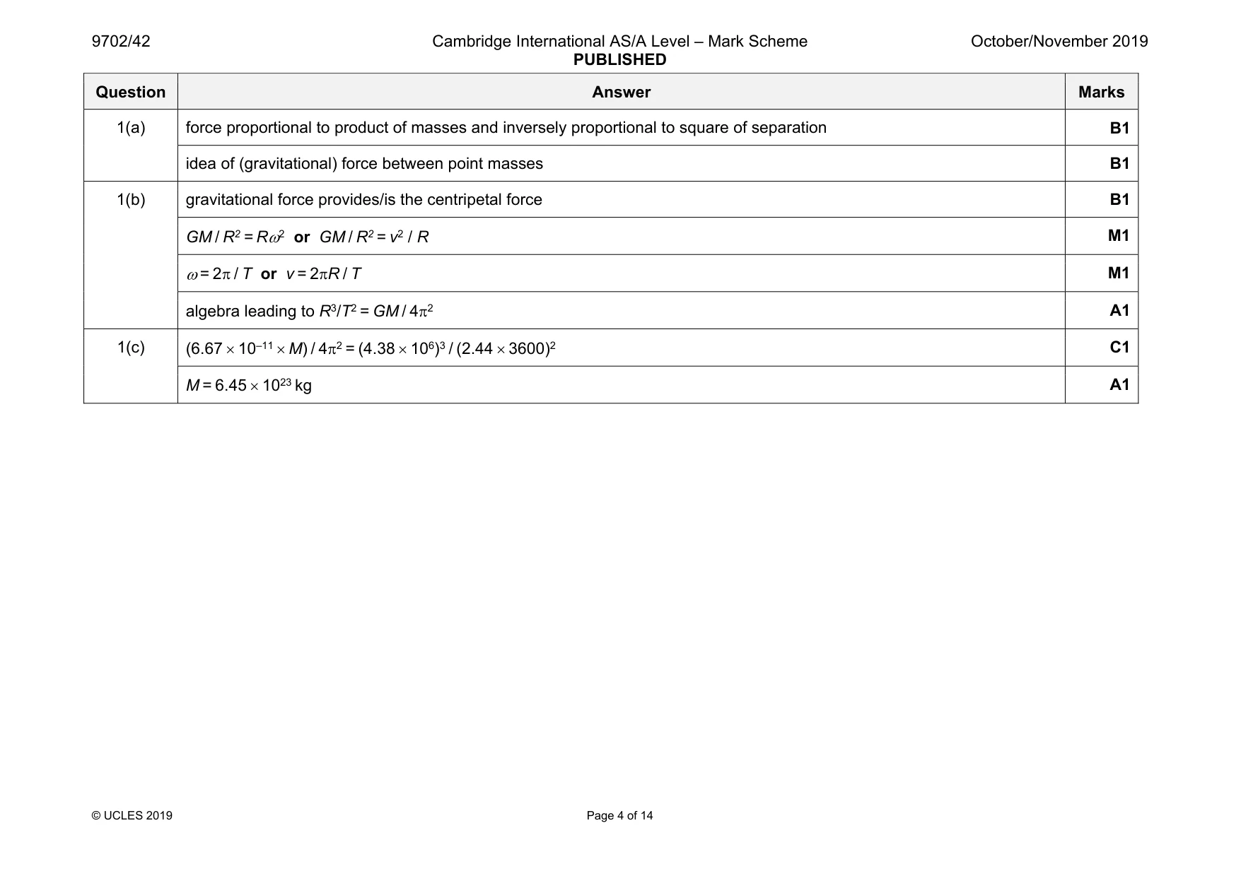
Mark scheme: 1(a) force proportional to product of masses and inversely proportional to square of separation B1 idea of (gravitational) force between point masses B1 1(b) gravitational force provides/is the centripetal force B1 GM / R2 = Rω2 or GM / R2 = v2 / R M1 ω = 2π / T or v = 2πR / T M1 algebra leading to R3/T2 = GM / 4π2 A1 1(c) (6.67 × 10⁻¹¹ × M) / 4π2 = (4.38 × 10⁶)3 / (2.44 × 3600)2 C1 M = 6.45 × 10²³ kg A1
Q2 · Smoke particles are suspended in still air
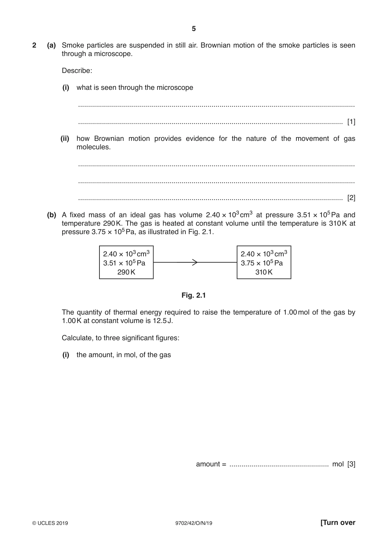
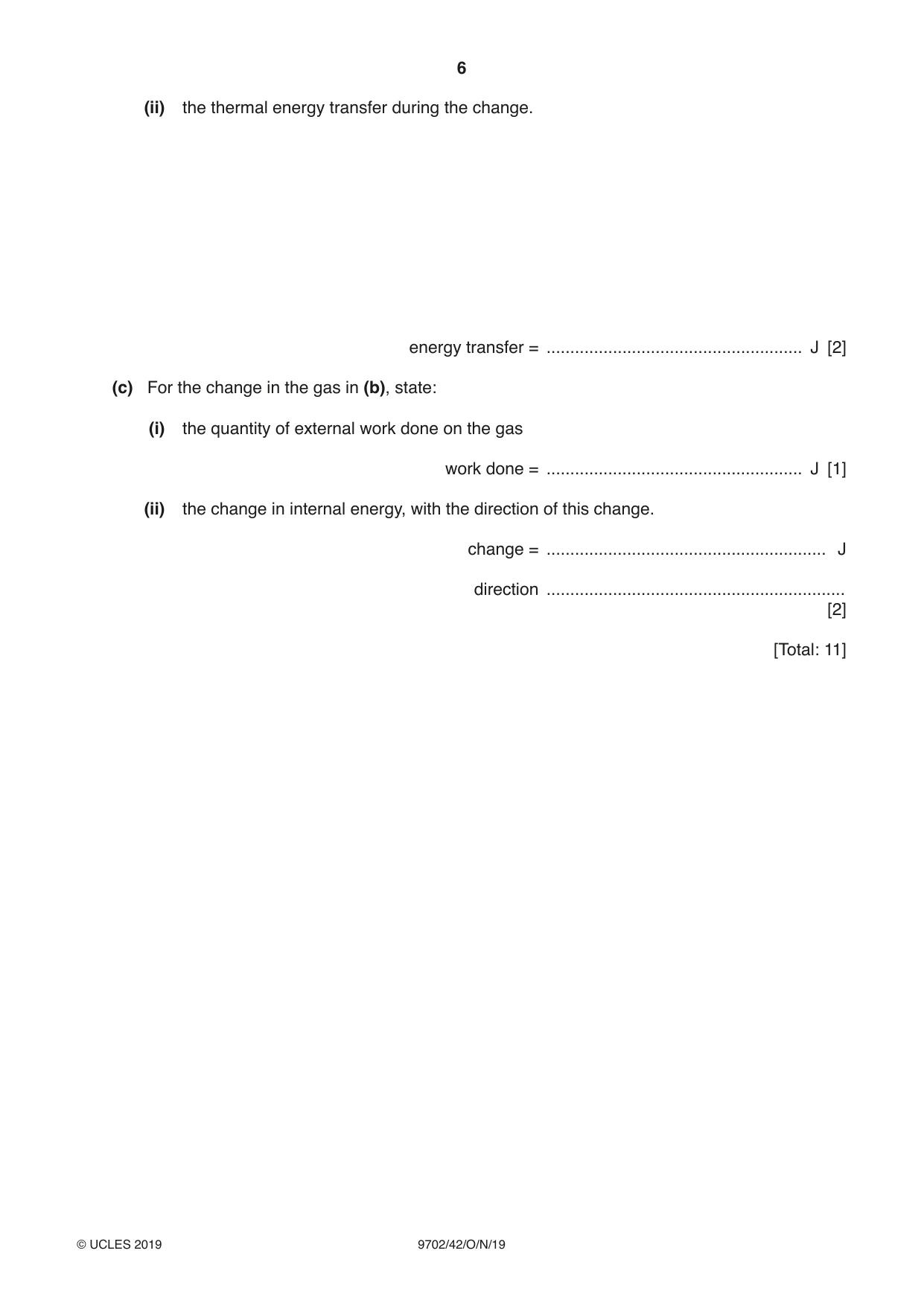
2 (a) Smoke particles are suspended in still air. Brownian motion of the smoke particles is seen through a microscope. Describe: (i) what is seen through the microscope ........................................................................................................................................... ..................................................................................................................................... [1] (ii) how Brownian motion provides evidence for the nature of the movement of gas molecules. ........................................................................................................................................... ........................................................................................................................................... ..................................................................................................................................... [2] (b) A fixed mass of an ideal gas has volume 2.40 × 103 cm3 at pressure 3.51 × 10⁵ Pa and temperature 290 K. The gas is heated at constant volume until the temperature is 310 K at pressure 3.75 × 10⁵ Pa, as illustrated in Fig. 2.1. 2.40 × 103 cm3 2.40 × 103 cm3 3.51 × 10⁵ Pa 3.75 × 10⁵ Pa 290 K 310 K Fig. 2.1 The quantity of thermal energy required to raise the temperature of 1.00 mol of the gas by 1.00 K at constant volume is 12.5 J. Calculate, to three significant figures: (i) the amount, in mol, of the gas amount = .................................................. mol [3] (ii) the thermal energy transfer during the change. energy transfer = ...................................................... J [2] (c) For the change in the gas in (b), state: (i) the quantity of external work done on the gas work done = ...................................................... J [1] (ii) the change in internal energy, with the direction of this change. change = ........................................................... J direction ............................................................... [2] [Total: 11]
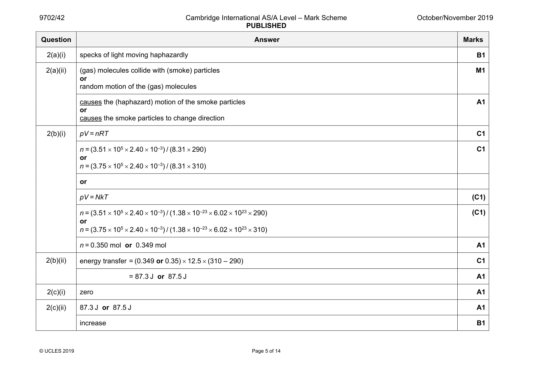
Mark scheme: 2(a)(i) specks of light moving haphazardly B1 2(a)(ii) (gas) molecules collide with (smoke) particles or random motion of the (gas) molecules M1 causes the (haphazard) motion of the smoke particles or causes the smoke particles to change direction A1 2(b)(i) pV = nRT C1 n = (3.51 × 105 × 2.40 × 10–3) / (8.31 × 290) or n = (3.75 × 105 × 2.40 × 10–3) / (8.31 × 310) C1 or pV = NkT (C1) n = (3.51 × 105 × 2.40 × 10–3) / (1.38 × 10–23 × 6.02 × 1023 × 290) or n = (3.75 × 105 × 2.40 × 10–3) / (1.38 × 10–23 × 6.02 × 1023 × 310) (C1) n = 0.350 mol or 0.349 mol A1 2(b)(ii) energy transfer = (0.349 or 0.35) × 12.5 × (310 – 290) C1 = 87.3 J or 87.5 J A1 2(c)(i) zero A1 2(c)(ii) 87.3 J or 87.5 J A1 increase B1
Q3 · State what is meant by specific latent heat
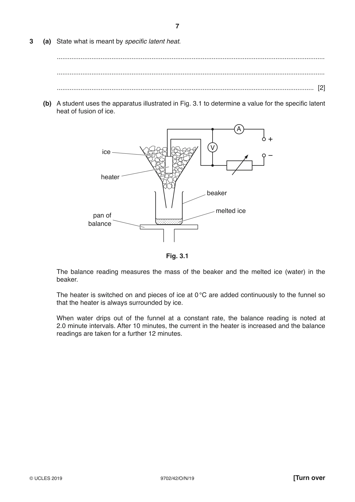
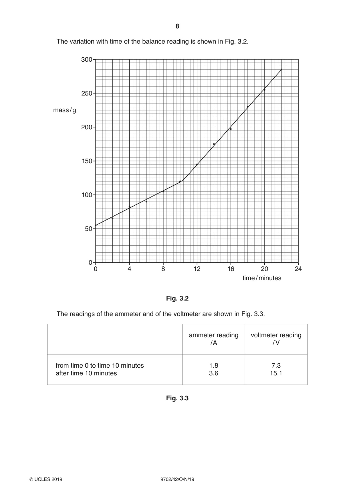
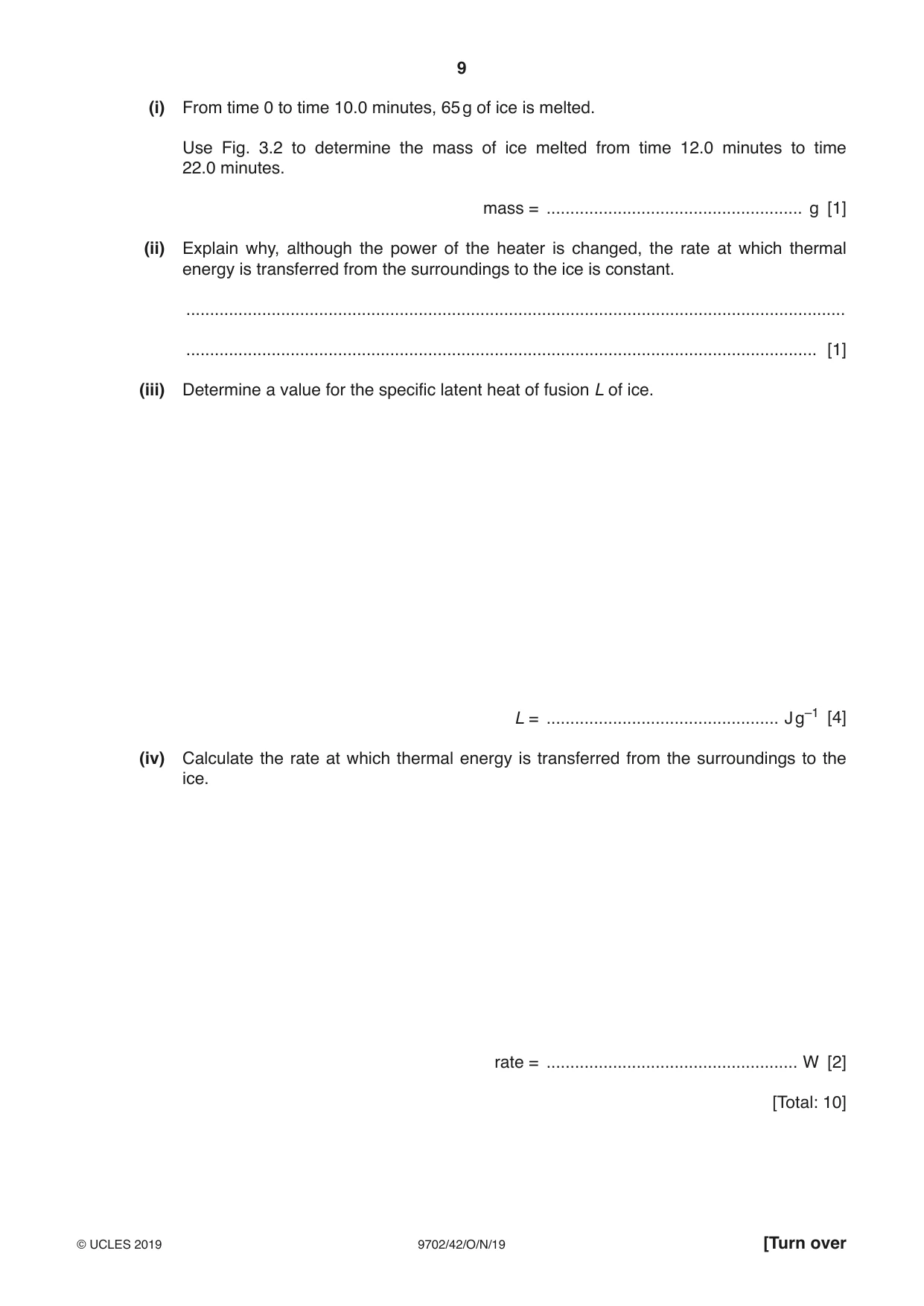
3 (a) State what is meant by specific latent heat. ................................................................................................................................................... ................................................................................................................................................... ............................................................................................................................................. [2] (b) A student uses the apparatus illustrated in Fig. 3.1 to determine a value for the specific latent heat of fusion of ice. A V ice heater beaker melted ice pan of balance Fig. 3.1 The balance reading measures the mass of the beaker and the melted ice (water) in the beaker. The heater is switched on and pieces of ice at 0 °C are added continuously to the funnel so that the heater is always surrounded by ice. When water drips out of the funnel at a constant rate, the balance reading is noted at 2.0 minute intervals. After 10 minutes, the current in the heater is increased and the balance readings are taken for a further 12 minutes. The variation with time of the balance reading is shown in Fig. 3.2. 300 250 mass / g 200 150 100 50 0 0 4 8 12 16 20 24 time / minutes Fig. 3.2 The readings of the ammeter and of the voltmeter are shown in Fig. 3.3. ammeter reading voltmeter reading / A / V from time 0 to time 10 minutes 1.8 7.3 after time 10 minutes 3.6 15.1 Fig. 3.3 (i) From time 0 to time 10.0 minutes, 65 g of ice is melted. Use Fig. 3.2 to determine the mass of ice melted from time 12.0 minutes to time 22.0 minutes. mass = ...................................................... g [1] (ii) Explain why, although the power of the heater is changed, the rate at which thermal energy is transferred from the surroundings to the ice is constant. ........................................................................................................................................... ..................................................................................................................................... [1] (iii) Determine a value for the specific latent heat of fusion L of ice. L = ................................................. J g–1 [4] (iv) Calculate the rate at which thermal energy is transferred from the surroundings to the ice. rate = ..................................................... W [2] [Total: 10]
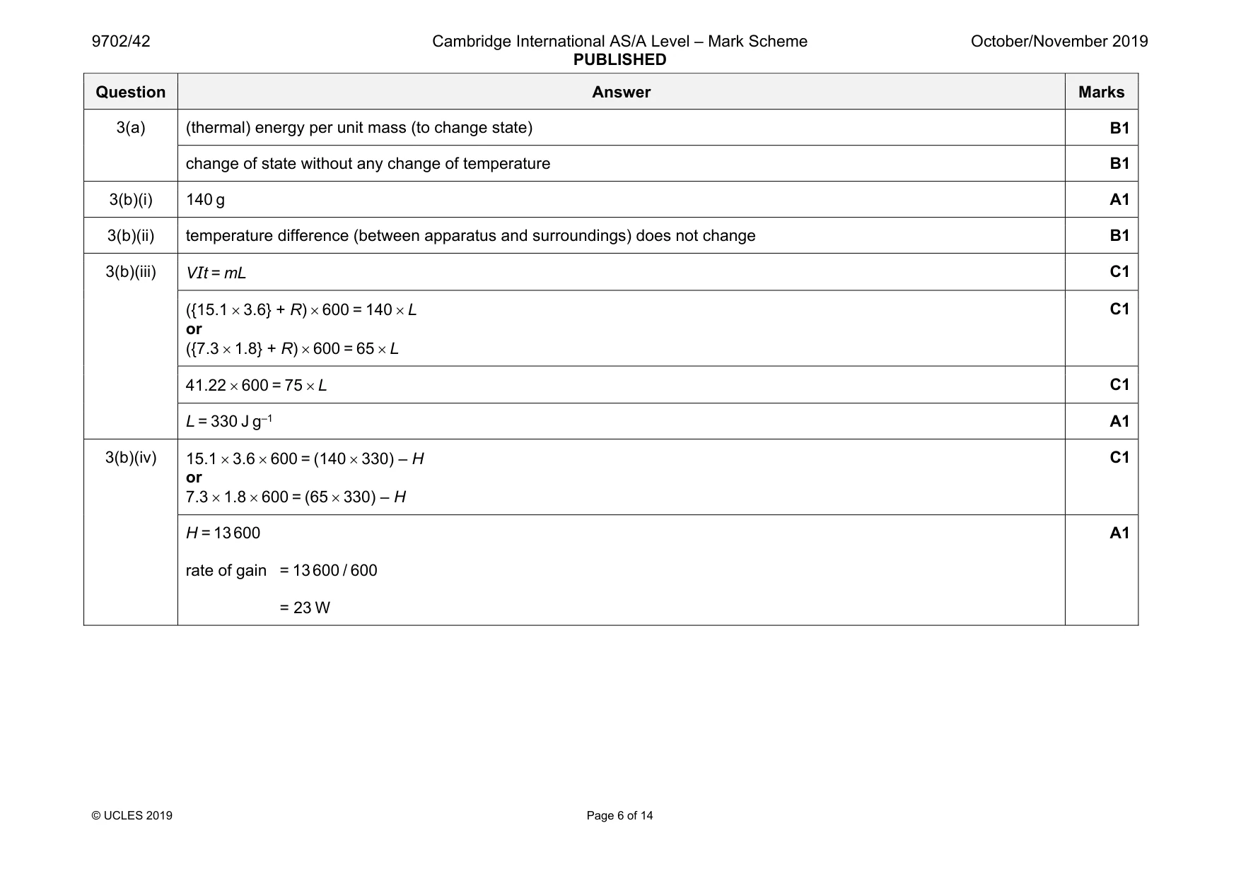
Mark scheme: 3(a) (thermal) energy per unit mass (to change state) B1 change of state without any change of temperature B1 3(b)(i) 140 g A1 3(b)(ii) temperature difference (between apparatus and surroundings) does not change B1 3(b)(iii) VIt = mL C1 ({15.1 × 3.6} + R) × 600 = 140 × L or ({7.3 × 1.8} + R) × 600 = 65 × L C1 41.22 × 600 = 75 × L C1 L = 330 J g–1 A1 3(b)(iv) 15.1 × 3.6 × 600 = (140 × 330) – H or 7.3 × 1.8 × 600 = (65 × 330) – H C1 H = 13 600 rate of gain = 13 600 / 600 = 23 W A1
More questions on Specific heat capacity and specific latent heat
Q4 · A ball of mass M is held on a horizontal surface by two identical extended springs, as…
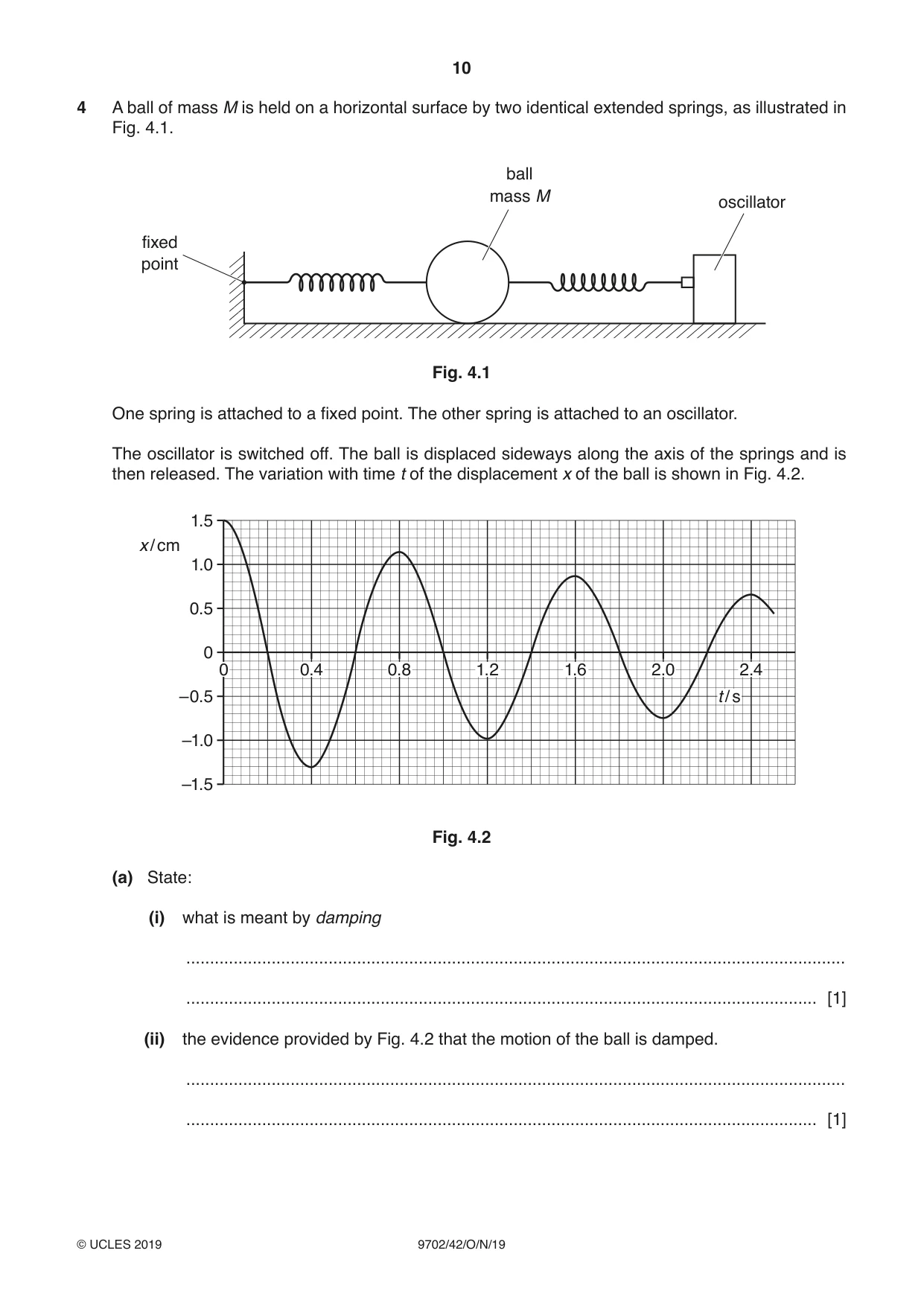
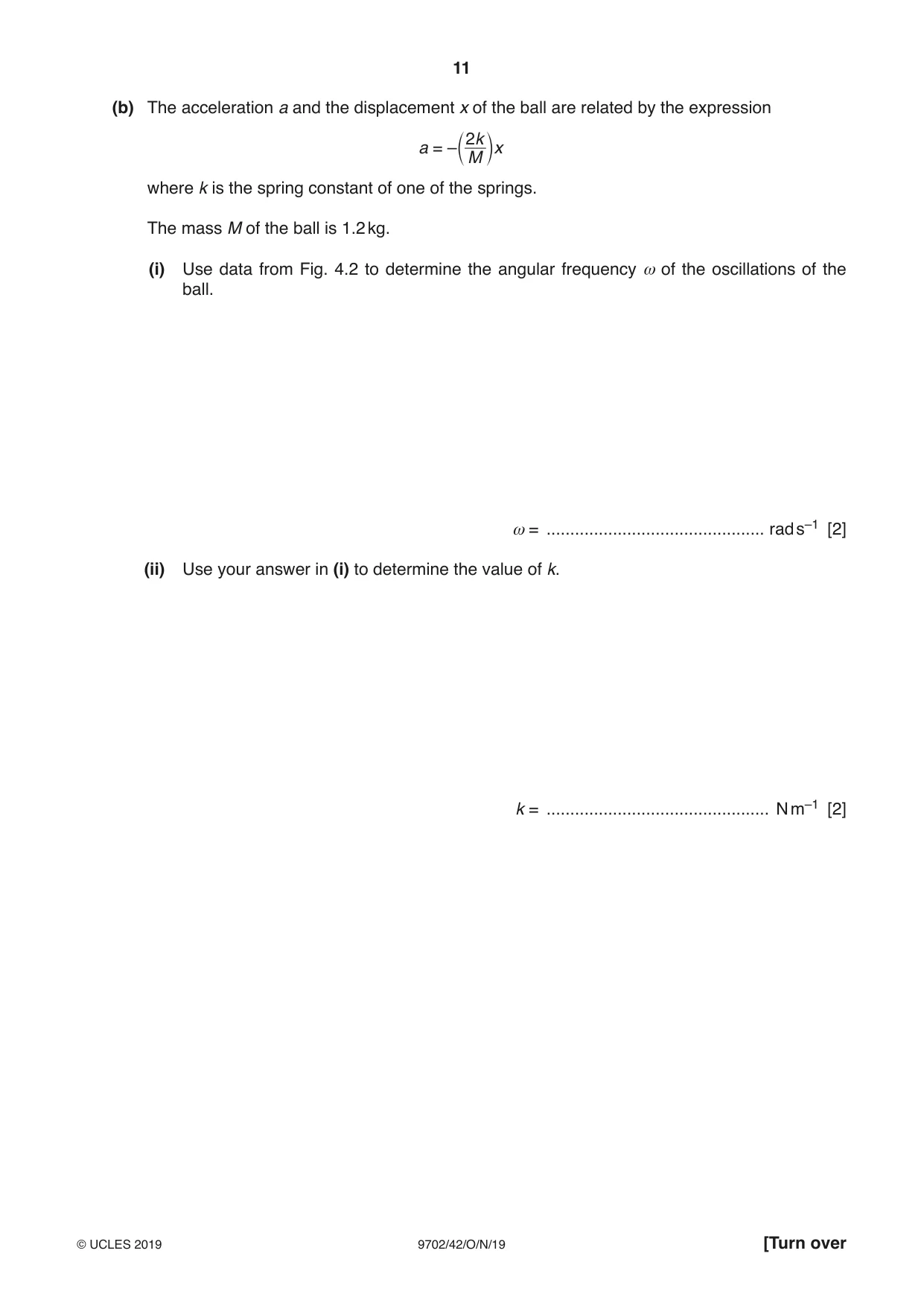
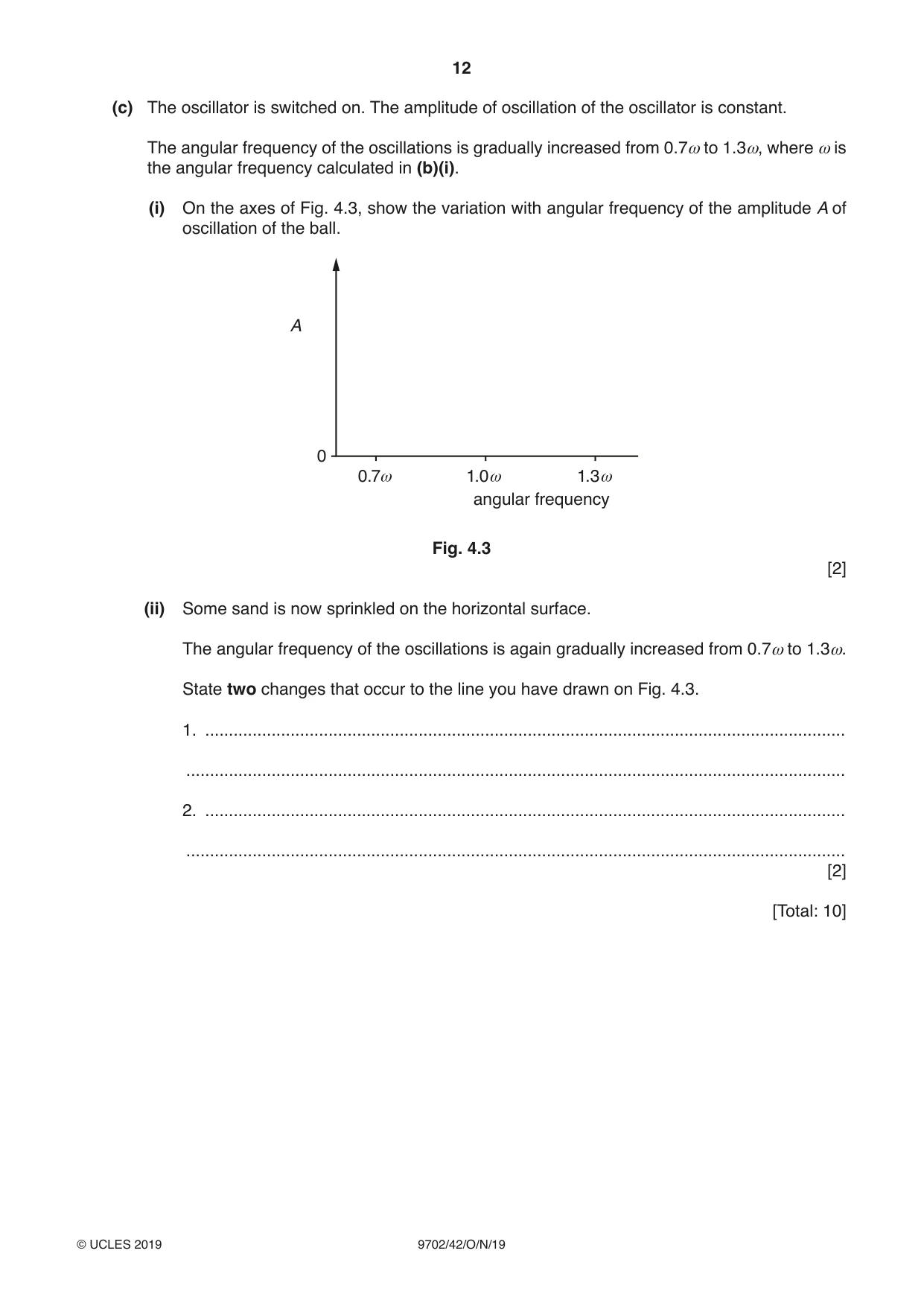
4 A ball of mass M is held on a horizontal surface by two identical extended springs, as illustrated in Fig. 4.1. ball mass M oscillator fixed point Fig. 4.1 One spring is attached to a fixed point. The other spring is attached to an oscillator. The oscillator is switched off. The ball is displaced sideways along the axis of the springs and is then released. The variation with time t of the displacement x of the ball is shown in Fig. 4.2. 1.5 x / cm 1.0 0.5 0 0 0.4 0.8 1.2 1.6 2.0 2.4 –0.5 t / s –1.0 –1.5 Fig. 4.2 (a) State: (i) what is meant by damping ........................................................................................................................................... ..................................................................................................................................... [1] (ii) the evidence provided by Fig. 4.2 that the motion of the ball is damped. ........................................................................................................................................... ..................................................................................................................................... [1] (b) The acceleration a and the displacement x of the ball are related by the expression 2 k a = – x c M m where k is the spring constant of one of the springs. The mass M of the ball is 1.2 kg. (i) Use data from Fig. 4.2 to determine the angular frequency ω of the oscillations of the ball. ω = .............................................. rad s–1 [2] (ii) Use your answer in (i) to determine the value of k. k = ............................................... N m–1 [2] (c) The oscillator is switched on. The amplitude of oscillation of the oscillator is constant. The angular frequency of the oscillations is gradually increased from 0.7ω to 1.3ω, where ω is the angular frequency calculated in (b)(i). (i) On the axes of Fig. 4.3, show the variation with angular frequency of the amplitude A of oscillation of the ball. A 0 0.7ω 1.0ω 1.3ω angular frequency Fig. 4.3 [2] (ii) Some sand is now sprinkled on the horizontal surface. The angular frequency of the oscillations is again gradually increased from 0.7ω to 1.3ω. State two changes that occur to the line you have drawn on Fig. 4.3. 1. ....................................................................................................................................... ........................................................................................................................................... 2. ....................................................................................................................................... ........................................................................................................................................... [2] [Total: 10]
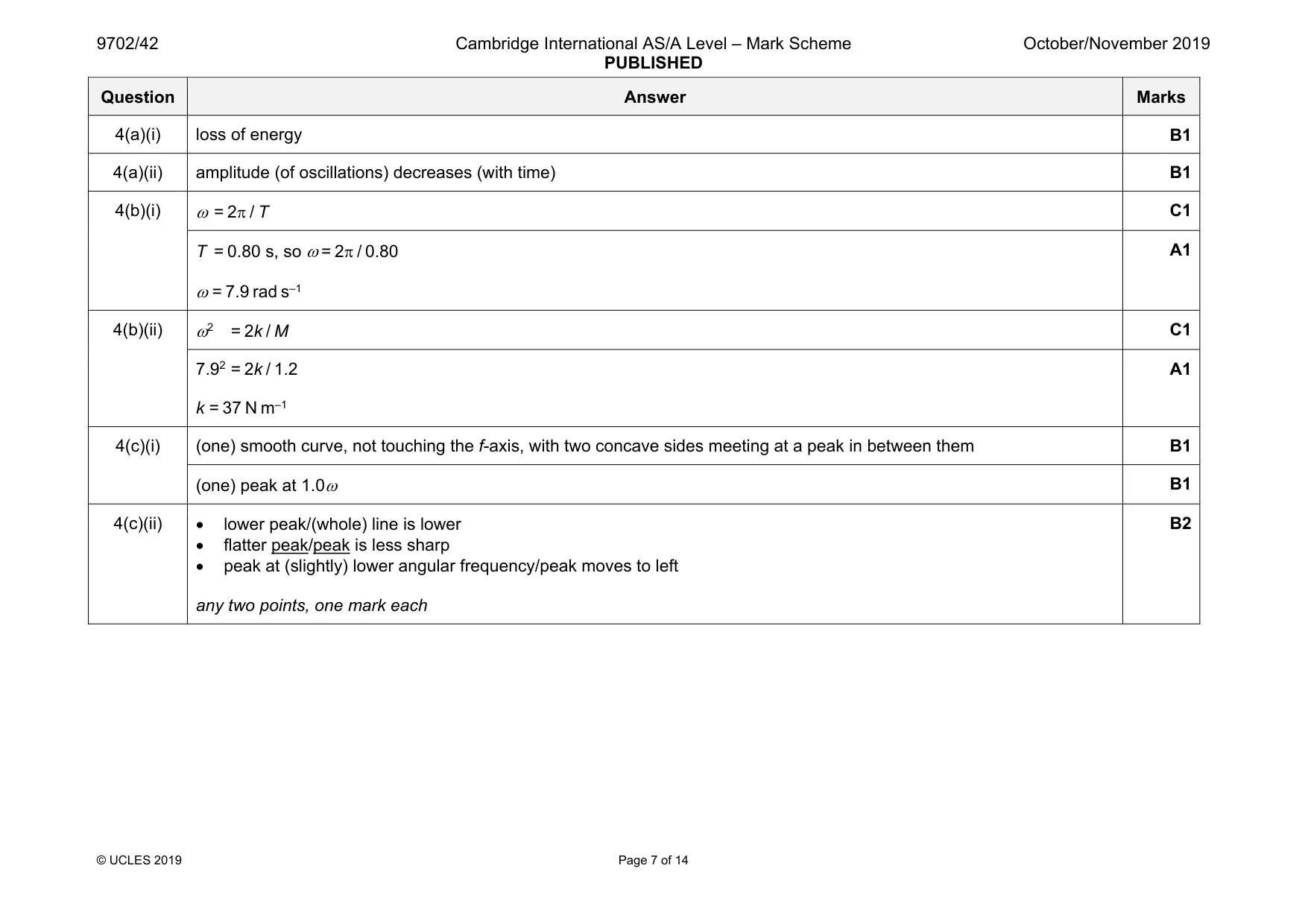
Mark scheme: 4(a)(i) loss of energy B1 4(a)(ii) amplitude (of oscillations) decreases (with time) B1 4(b)(i) ω = 2π / T C1 T = 0.80 s, so ω = 2π / 0.80 ω = 7.9 rad s–1 A1 4(b)(ii) ω2 = 2k / M C1 7.92 = 2k / 1.2 k = 37 N m–1 A1 4(c)(i) (one) smooth curve, not touching the f-axis, with two concave sides meeting at a peak in between them B1 (one) peak at 1.0ω B1 4(c)(ii) • lower peak/(whole) line is lower • flatter peak/peak is less sharp • peak at (slightly) lower angular frequency/peak moves to left any two points, one mark each B2
Q5 · State what is meant by the specific acoustic impedance of a medium
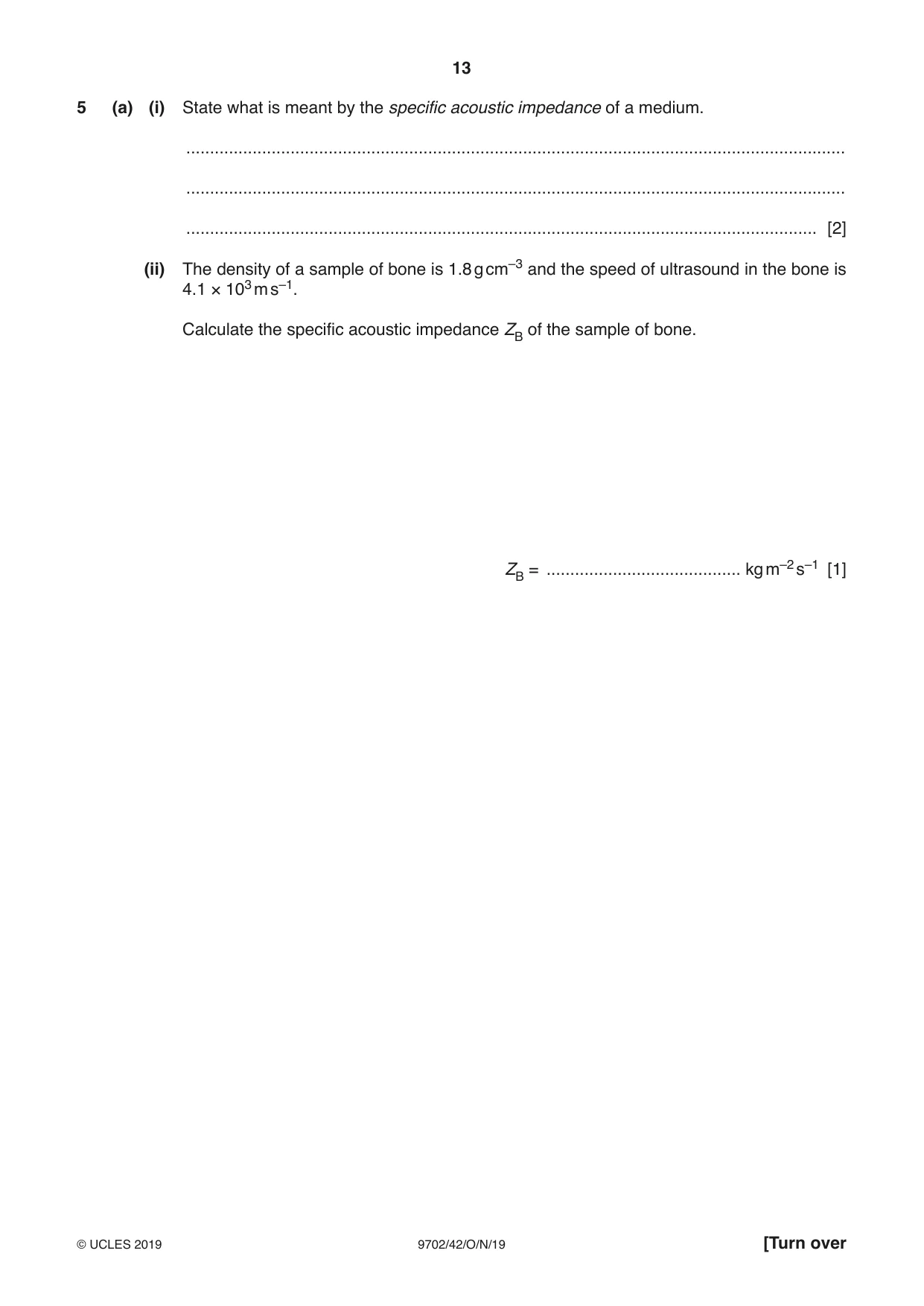
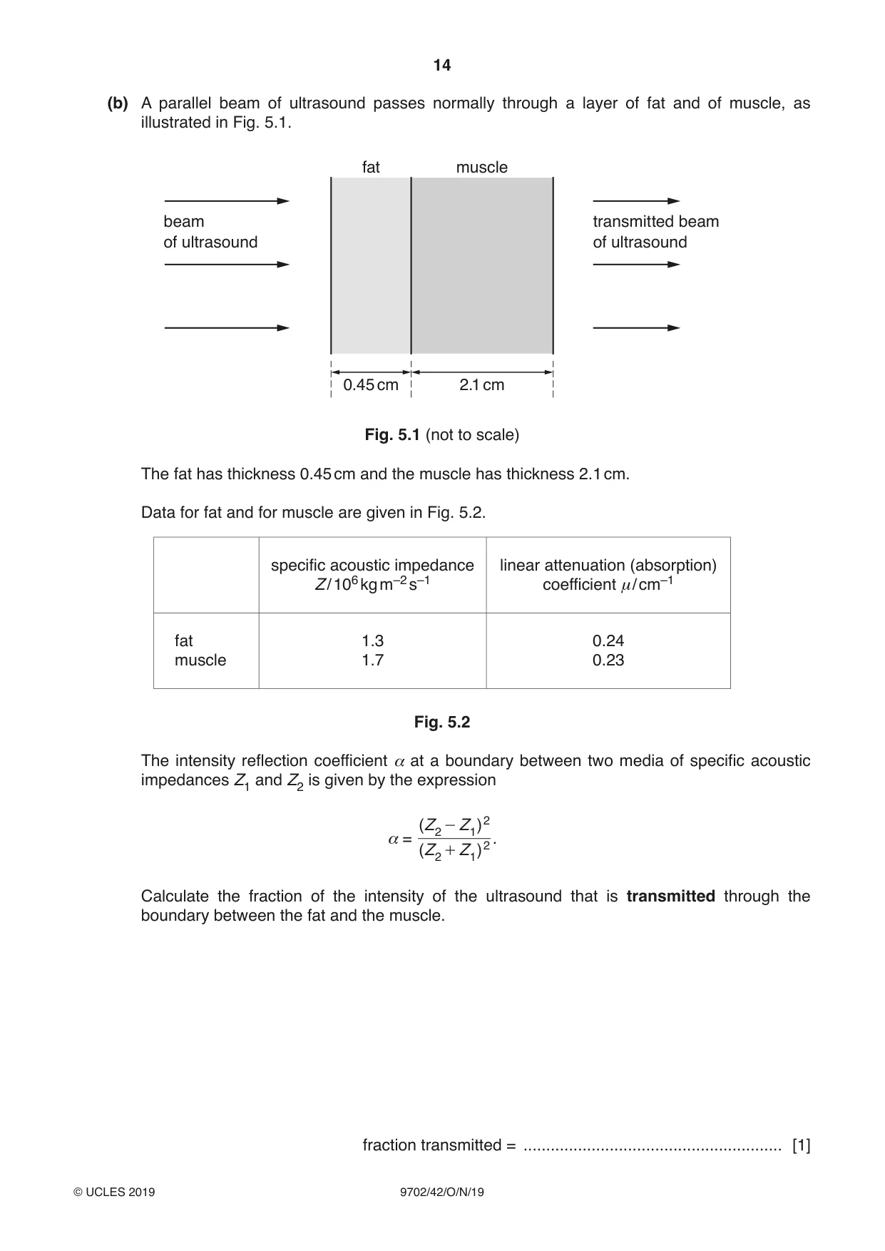
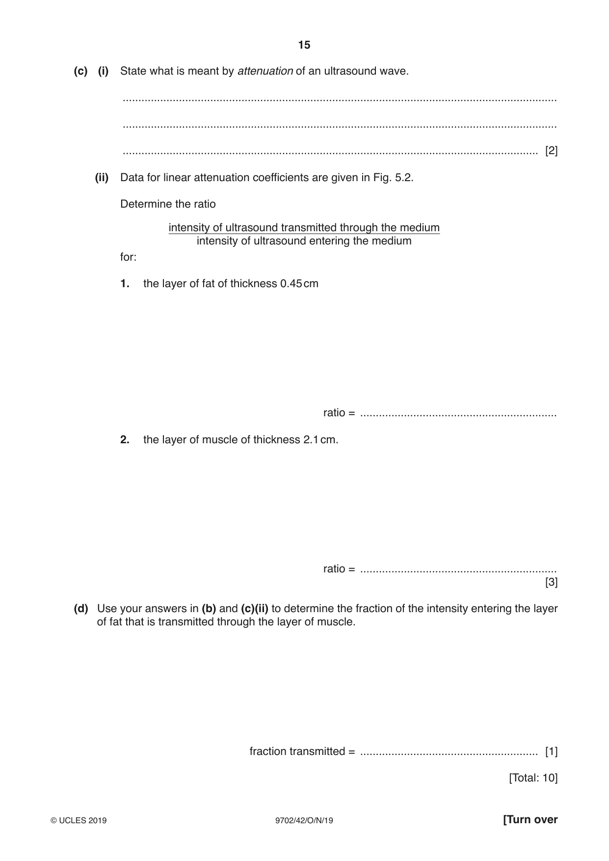
5 (a) (i) State what is meant by the specific acoustic impedance of a medium. ........................................................................................................................................... ........................................................................................................................................... ..................................................................................................................................... [2] (ii) The density of a sample of bone is 1.8 g cm–3 and the speed of ultrasound in the bone is 4.1 × 10³ m s–1. Calculate the specific acoustic impedance ZB of the sample of bone. ZB = ......................................... kg m–2 s–1 [1] (b) A parallel beam of ultrasound passes normally through a layer of fat and of muscle, as illustrated in Fig. 5.1. fat muscle beam transmitted beam of ultrasound of ultrasound 0.45 cm 2.1 cm Fig. 5.1 (not to scale) The fat has thickness 0.45 cm and the muscle has thickness 2.1 cm. Data for fat and for muscle are given in Fig. 5.2. specific acoustic impedance linear attenuation (absorption) Z / 106 kg m–2 s–1 coefficient μ/ cm–1 fat 1.3 0.24 muscle 1.7 0.23 Fig. 5.2 The intensity reflection coefficient α at a boundary between two media of specific acoustic impedances Z1 and Z2 is given by the expression - (Z 2 Z 1) 2 α = . + (Z 2 Z 1) 2 Calculate the fraction of the intensity of the ultrasound that is transmitted through the boundary between the fat and the muscle. fraction transmitted = ......................................................... [1] (c) (i) State what is meant by attenuation of an ultrasound wave. ........................................................................................................................................... ........................................................................................................................................... ..................................................................................................................................... [2] (ii) Data for linear attenuation coefficients are given in Fig. 5.2. Determine the ratio intensity of ultrasound transmitted through the medium intensity of ultrasound entering the medium for: 1. the layer of fat of thickness 0.45 cm ratio = ............................................................... 2. the layer of muscle of thickness 2.1 cm. ratio = ............................................................... [3] (d) Use your answers in (b) and (c)(ii) to determine the fraction of the intensity entering the layer of fat that is transmitted through the layer of muscle. fraction transmitted = ......................................................... [1] [Total: 10]
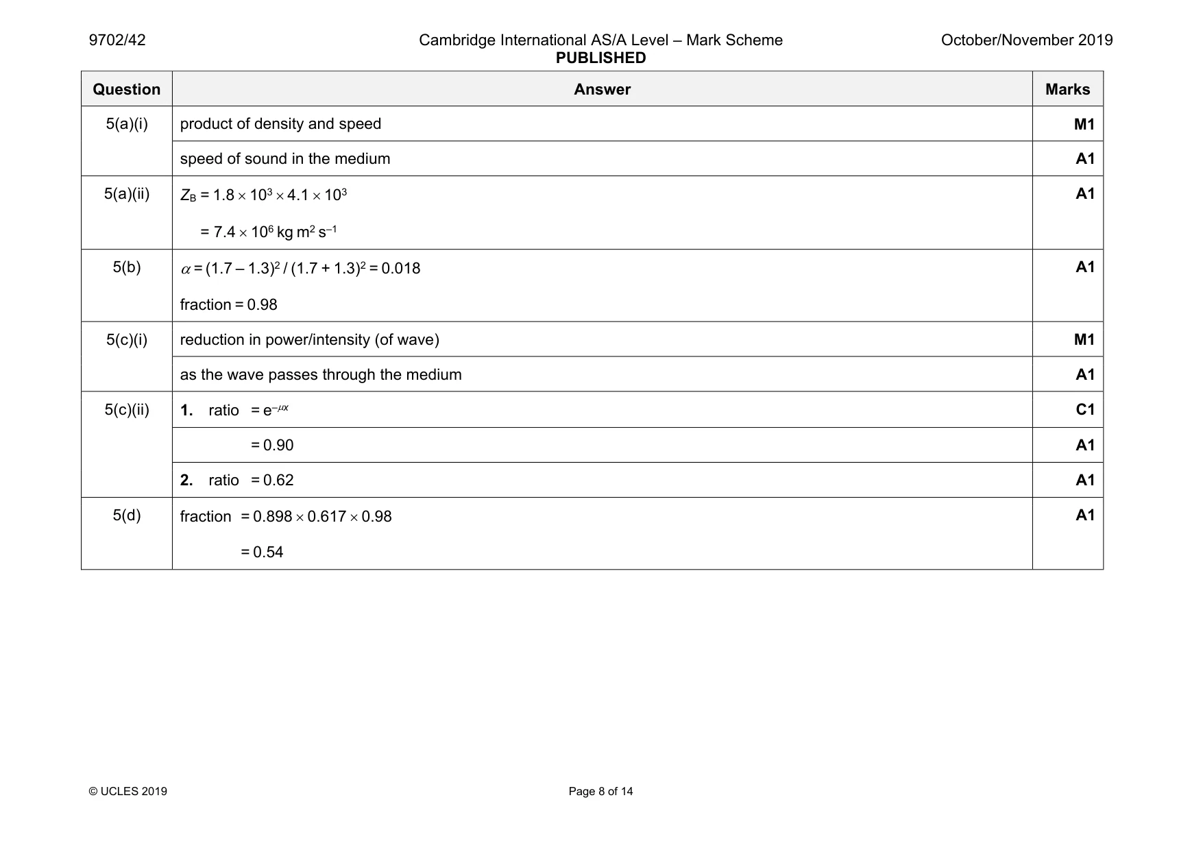
Mark scheme: 5(a)(i) product of density and speed M1 speed of sound in the medium A1 5(a)(ii) ZB = 1.8 × 103 × 4.1 × 103 = 7.4 × 10⁶ kg m2 s–1 A1 5(b) α = (1.7 – 1.3)2 / (1.7 + 1.3)2 = 0.018 fraction = 0.98 A1 5(c)(i) reduction in power/intensity (of wave) M1 as the wave passes through the medium A1 5(c)(ii) 1. ratio = e–µx C1 = 0.90 A1 2. ratio = 0.62 A1 5(d) fraction = 0.898 × 0.617 × 0.98 = 0.54 A1
Q6 · The variation with time of the displacement of an amplitude-modulated (AM) wave is shown…
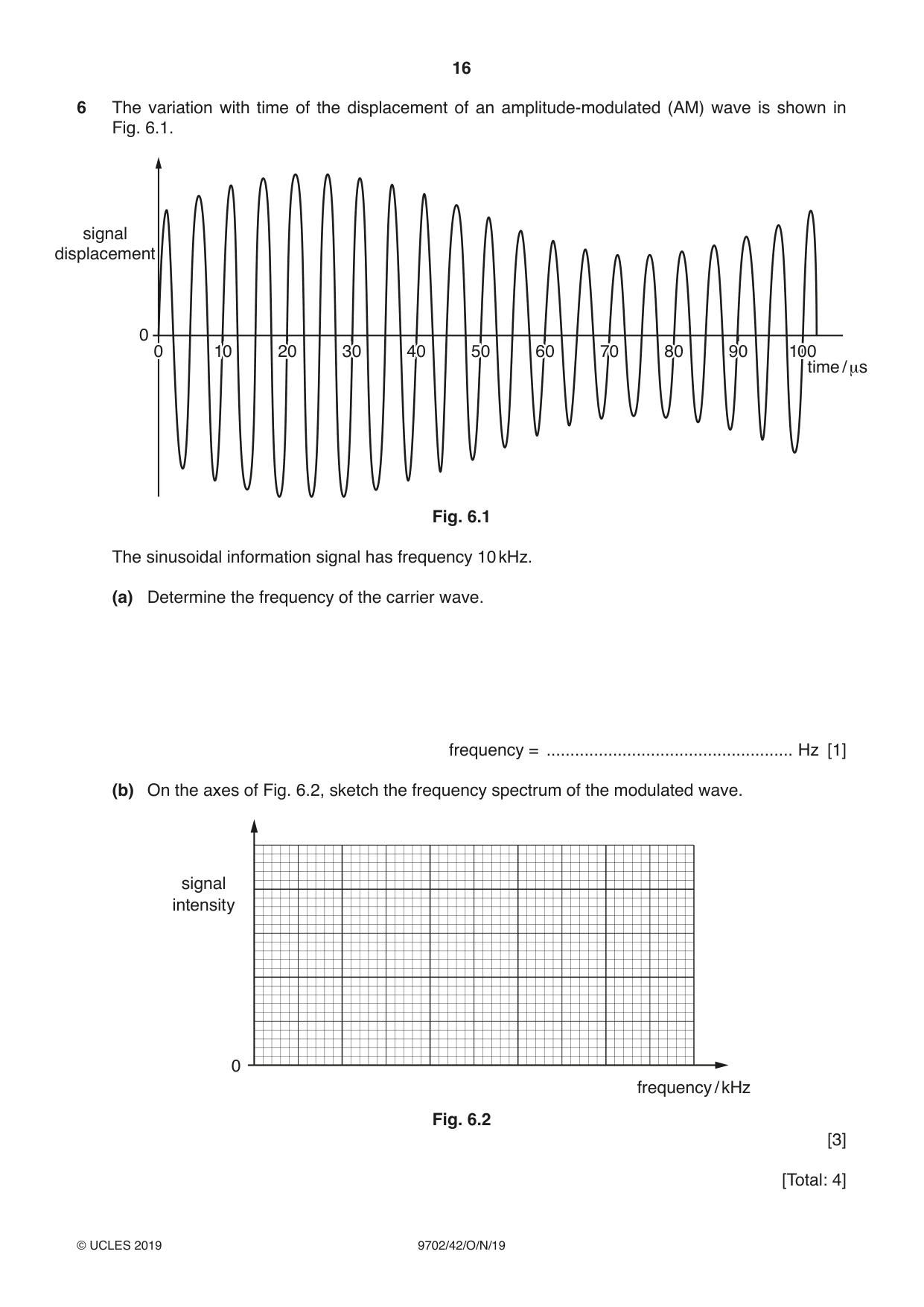
6 The variation with time of the displacement of an amplitude-modulated (AM) wave is shown in Fig. 6.1. signal displacement 0 0 10 20 30 40 50 60 70 80 90 100 time / μs Fig. 6.1 The sinusoidal information signal has frequency 10 kHz. (a) Determine the frequency of the carrier wave. frequency = .................................................... Hz [1] (b) On the axes of Fig. 6.2, sketch the frequency spectrum of the modulated wave. signal intensity 0 frequency / kHz Fig. 6.2 [3] [Total: 4]
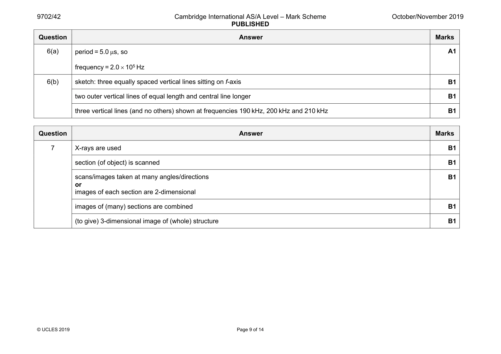
Mark scheme: 6(a) frequency = 2.0 × 10⁵ Hz A1 6(b) sketch: three equally spaced vertical lines sitting on f-axis B1 two outer vertical lines of equal length and central line longer B1 three vertical lines (and no others) shown at frequencies 190 kHz, 200 kHz and 210 kHz B1
Q7 · Describe the principles of computed tomography (CT) scanning
7 Describe the principles of computed tomography (CT) scanning. .......................................................................................................................................................... .......................................................................................................................................................... .......................................................................................................................................................... .......................................................................................................................................................... .......................................................................................................................................................... .......................................................................................................................................................... .......................................................................................................................................................... .................................................................................................................................................... [5]
Mark scheme: 7 X-rays are used B1 section (of object) is scanned B1 scans/images taken at many angles/directions or images of each section are 2-dimensional B1 images of (many) sections are combined B1 (to give) 3-dimensional image of (whole) structure B1
Q8 · Electrons enter a rectangular slice PQRSEFGH of a semiconductor material at right-angles…
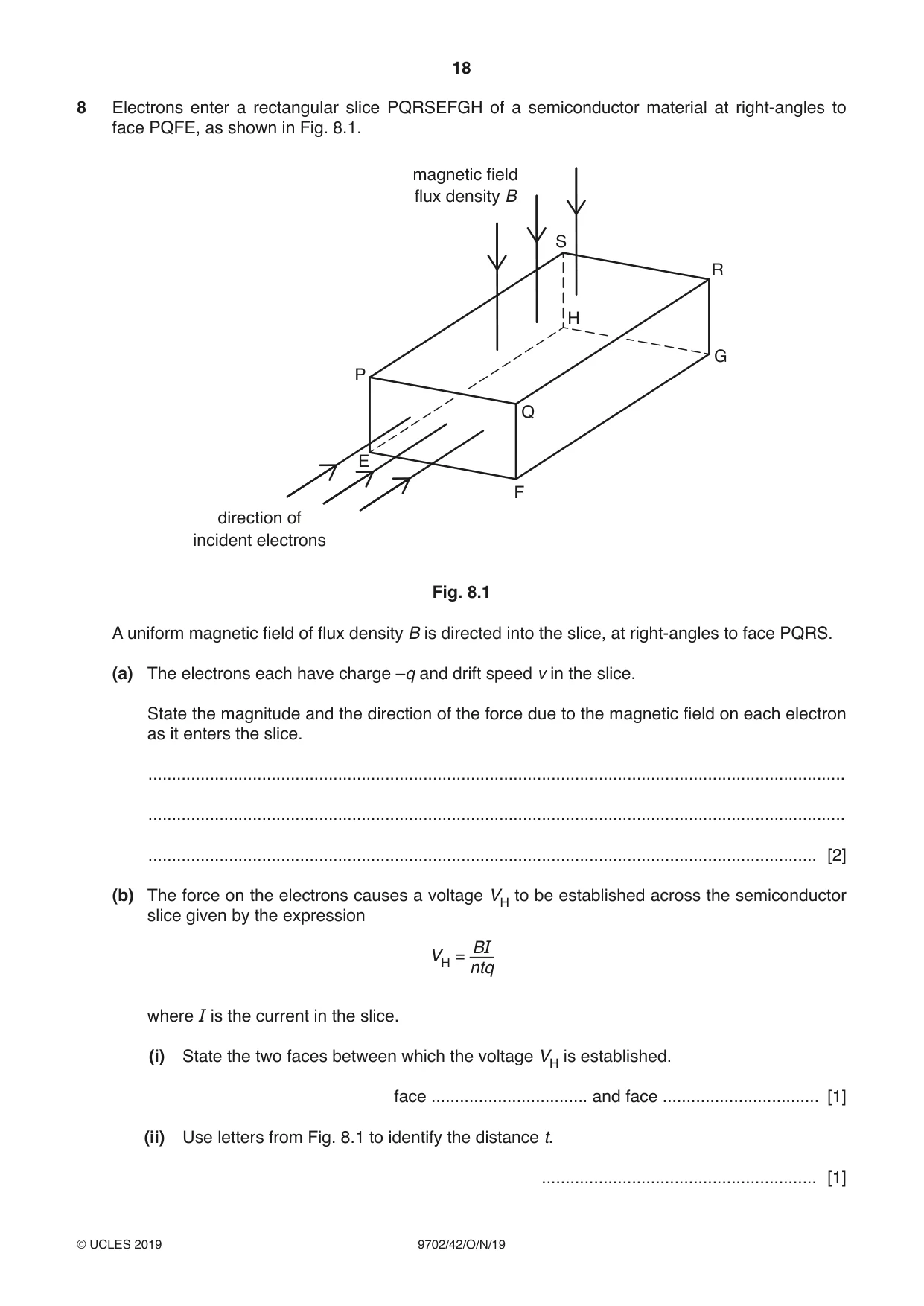
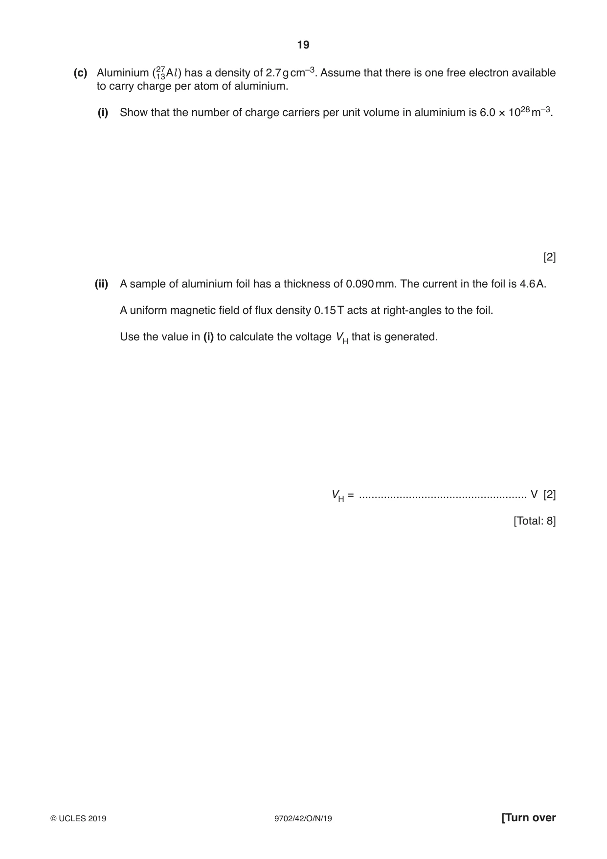
8 Electrons enter a rectangular slice PQRSEFGH of a semiconductor material at right-angles to face PQFE, as shown in Fig. 8.1. magnetic field flux density B S R H G P Q E F direction of incident electrons Fig. 8.1 A uniform magnetic field of flux density B is directed into the slice, at right-angles to face PQRS. (a) The electrons each have charge –q and drift speed v in the slice. State the magnitude and the direction of the force due to the magnetic field on each electron as it enters the slice. ................................................................................................................................................... ................................................................................................................................................... ............................................................................................................................................. [2] (b) The force on the electrons causes a voltage VH to be established across the semiconductor slice given by the expression BI VH = ntq where I is the current in the slice. (i) State the two faces between which the voltage VH is established. face ................................. and face ................................. [1] (ii) Use letters from Fig. 8.1 to identify the distance t. .......................................................... [1] (c) Aluminium (2713 Al ) has a density of 2.7 g cm–3. Assume that there is one free electron available to carry charge per atom of aluminium. (i) Show that the number of charge carriers per unit volume in aluminium is 6.0 × 1028 m–3. [2] (ii) A sample of aluminium foil has a thickness of 0.090 mm. The current in the foil is 4.6 A. A uniform magnetic field of flux density 0.15 T acts at right-angles to the foil. Use the value in (i) to calculate the voltage VH that is generated. VH = ...................................................... V [2] [Total: 8]
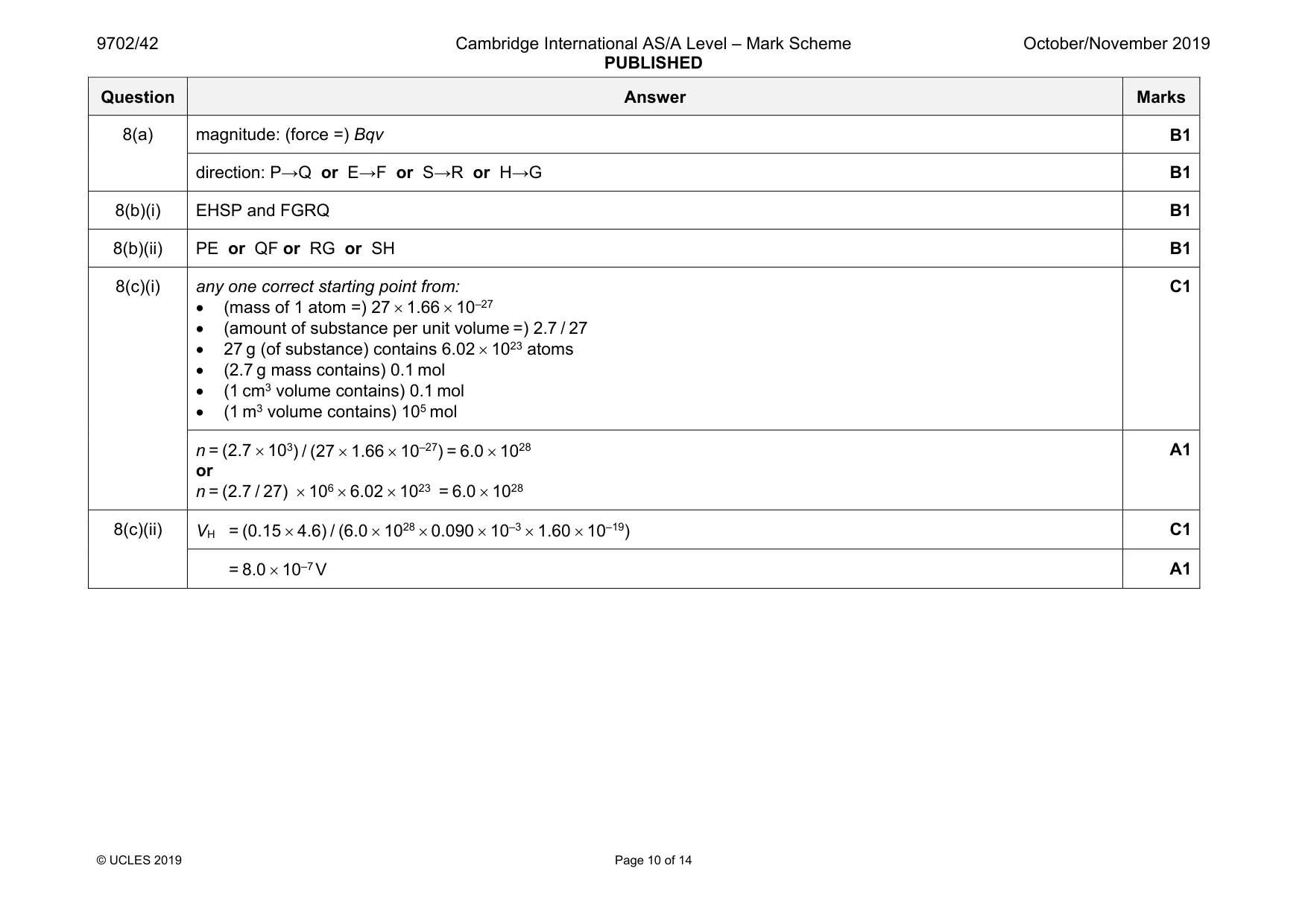
Mark scheme: 8(a) magnitude: (force =) Bqv B1 direction: P→Q or E→F or S→R or H→G B1 8(b)(i) EHSP and FGRQ B1 8(b)(ii) PE or QF or RG or SH B1 8(c)(i) any one correct starting point from: • (mass of 1 atom =) 27 × 1.66 × 10–27 • (amount of substance per unit volume =) 2.7 / 27 • 27 g (of substance) contains 6.02 × 10²³ atoms • (2.7 g mass contains) 0.1 mol • (1 cm3 volume contains) 0.1 mol • (1 m3 volume contains) 105 mol C1 n = (2.7 × 10³) / (27 × 1.66 × 10–27) = 6.0 × 1028 or n = (2.7 / 27) × 106 × 6.02 × 1023 = 6.0 × 1028 A1 8(c)(ii) VH = (0.15 × 4.6) / (6.0 × 1028 × 0.090 × 10–3 × 1.60 × 10–19) C1 = 8.0 × 10⁻⁷ V A1
Q9 · Define what is meant by electric potential at a point
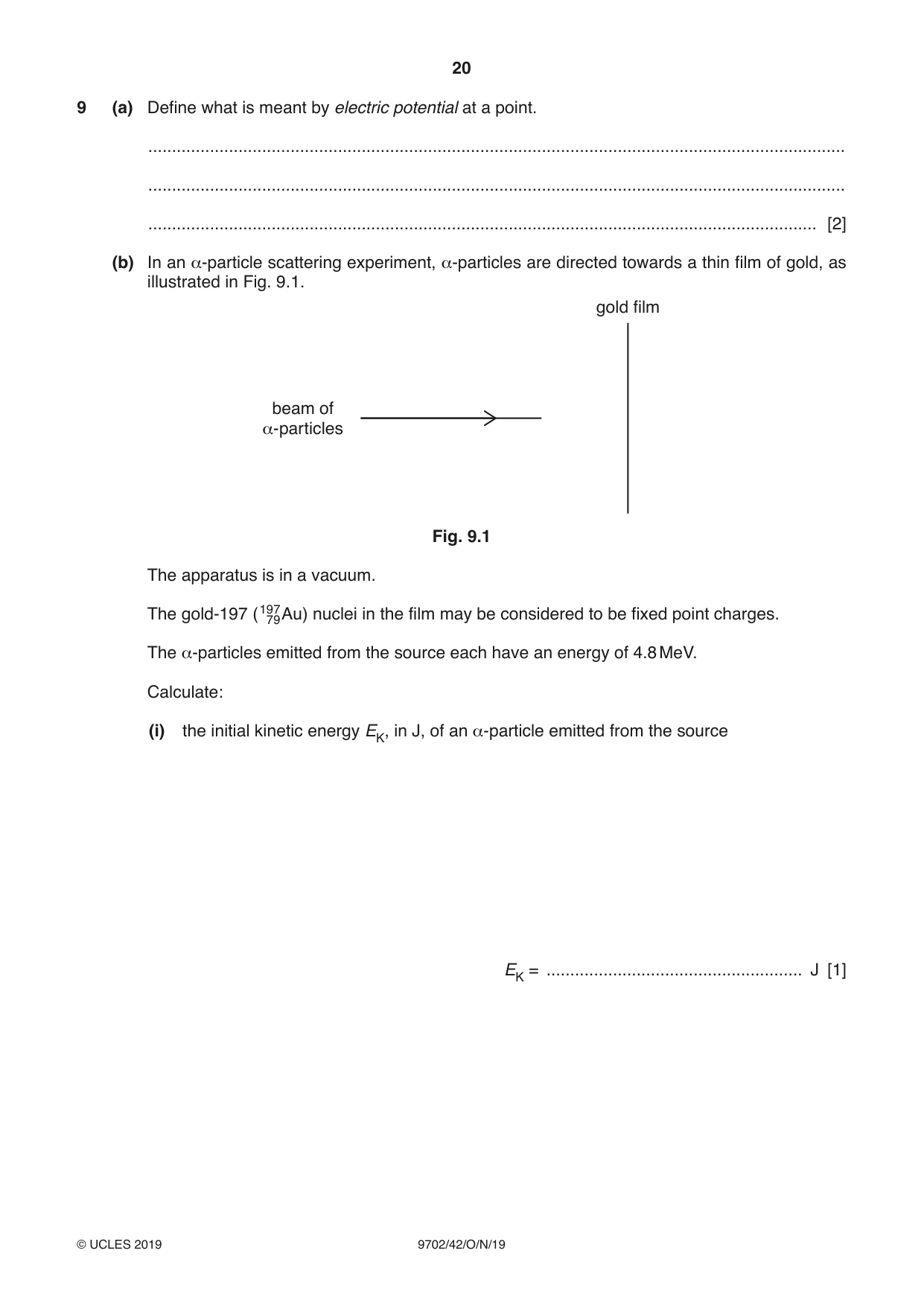
9 (a) Define what is meant by electric potential at a point. ................................................................................................................................................... ................................................................................................................................................... ............................................................................................................................................. [2] (b) In an α-particle scattering experiment, α-particles are directed towards a thin film of gold, as illustrated in Fig. 9.1. gold film beam of α-particles Fig. 9.1 The apparatus is in a vacuum. The gold-197 (19779 Au) nuclei in the film may be considered to be fixed point charges. The α-particles emitted from the source each have an energy of 4.8 MeV. Calculate: (i) the initial kinetic energy EK, in J, of an α-particle emitted from the source EK = ...................................................... J [1] (ii) the distance d of closest approach of an α-particle to a gold nucleus. d = ..................................................... m [4] (c) Use your answer in (b)(ii) to comment on the possible diameter of a gold nucleus. ................................................................................................................................................... ............................................................................................................................................. [1] [Total: 8]
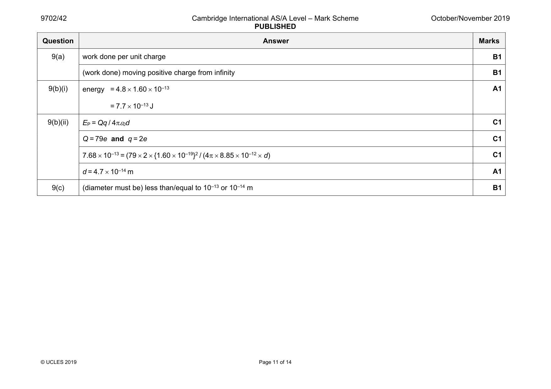
Mark scheme: 9(a) work done per unit charge B1 (work done) moving positive charge from infinity B1 9(b)(i) energy = 4.8 × 1.60 × 10–13 = 7.7 × 10⁻¹³ J A1 9(b)(ii) EP = Qq / 4πε0d C1 Q = 79e and q = 2e C1 7.68 × 10–13 = (79 × 2 × {1.60 × 10⁻¹⁹}2 / (4π × 8.85 × 10–12 × d) C1 d = 4.7 × 10⁻¹⁴ m A1 9(c) (diameter must be) less than/equal to 10–13 or 10–14 m B1
Q10 · The upper electron energy bands in an intrinsic semiconductor material are illustrated in…
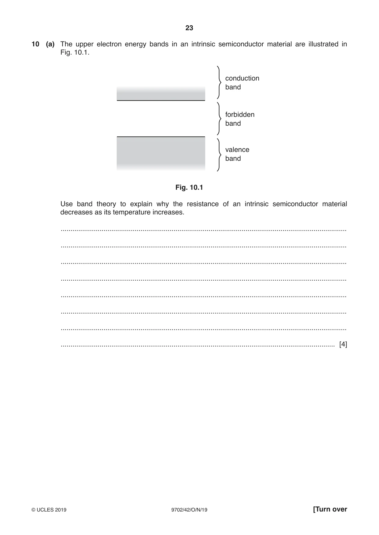
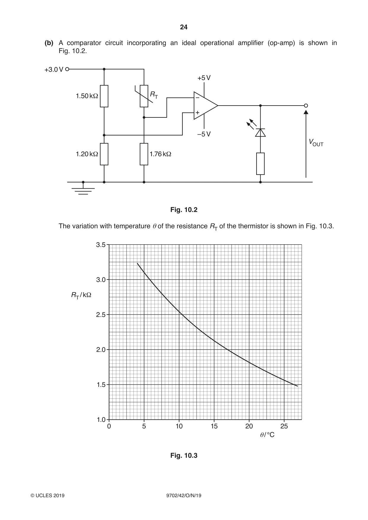
10 (a) The upper electron energy bands in an intrinsic semiconductor material are illustrated in Fig. 10.1. conduction band forbidden band valence band Fig. 10.1 Use band theory to explain why the resistance of an intrinsic semiconductor material decreases as its temperature increases. ................................................................................................................................................... ................................................................................................................................................... ................................................................................................................................................... ................................................................................................................................................... ................................................................................................................................................... ................................................................................................................................................... ................................................................................................................................................... ............................................................................................................................................. [4] (b) A comparator circuit incorporating an ideal operational amplifier (op-amp) is shown in Fig. 10.2. +3.0 V +5 V 1.50 kΩ RT –5 V VOUT 1.20 kΩ 1.76 kΩ Fig. 10.2 The variation with temperature θ of the resistance RT of the thermistor is shown in Fig. 10.3. 3.5 3.0 RT / kΩ 2.5 2.0 1.5 1.0 0 5 10 15 20 25 θ/ °C Fig. 10.3 (i) Determine the temperature at which the light-emitting diode (LED) in Fig. 10.2 switches on or off. temperature = ..................................................... °C [4] (ii) State and explain whether the thermistor is above or below the temperature calculated in (i) for the LED to emit light. ........................................................................................................................................... ........................................................................................................................................... ........................................................................................................................................... ..................................................................................................................................... [3] [Total: 11]
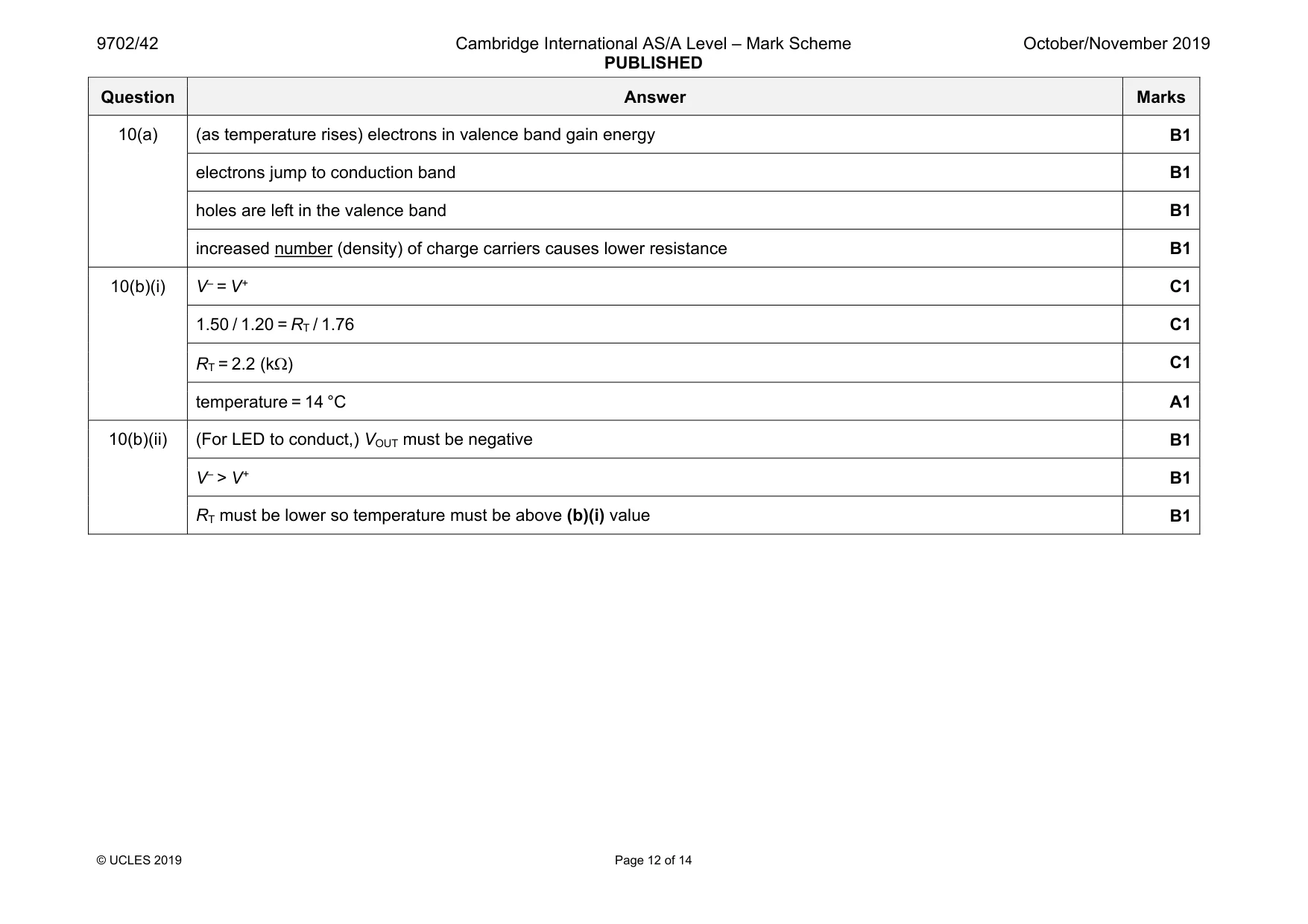
Mark scheme: 10(a) (as temperature rises) electrons in valence band gain energy B1 electrons jump to conduction band B1 holes are left in the valence band B1 increased number (density) of charge carriers causes lower resistance B1 10(b)(i) V– = V+ C1 1.50 / 1.20 = RT / 1.76 C1 RT = 2.2 (kΩ) C1 temperature = 14 °C A1 10(b)(ii) (For LED to conduct,) VOUT must be negative B1 V– > V+ B1 RT must be lower so temperature must be above (b)(i) value B1
Q11 · State Faraday’s law of electromagnetic induction
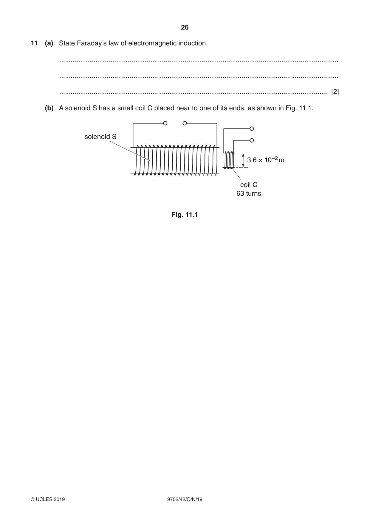
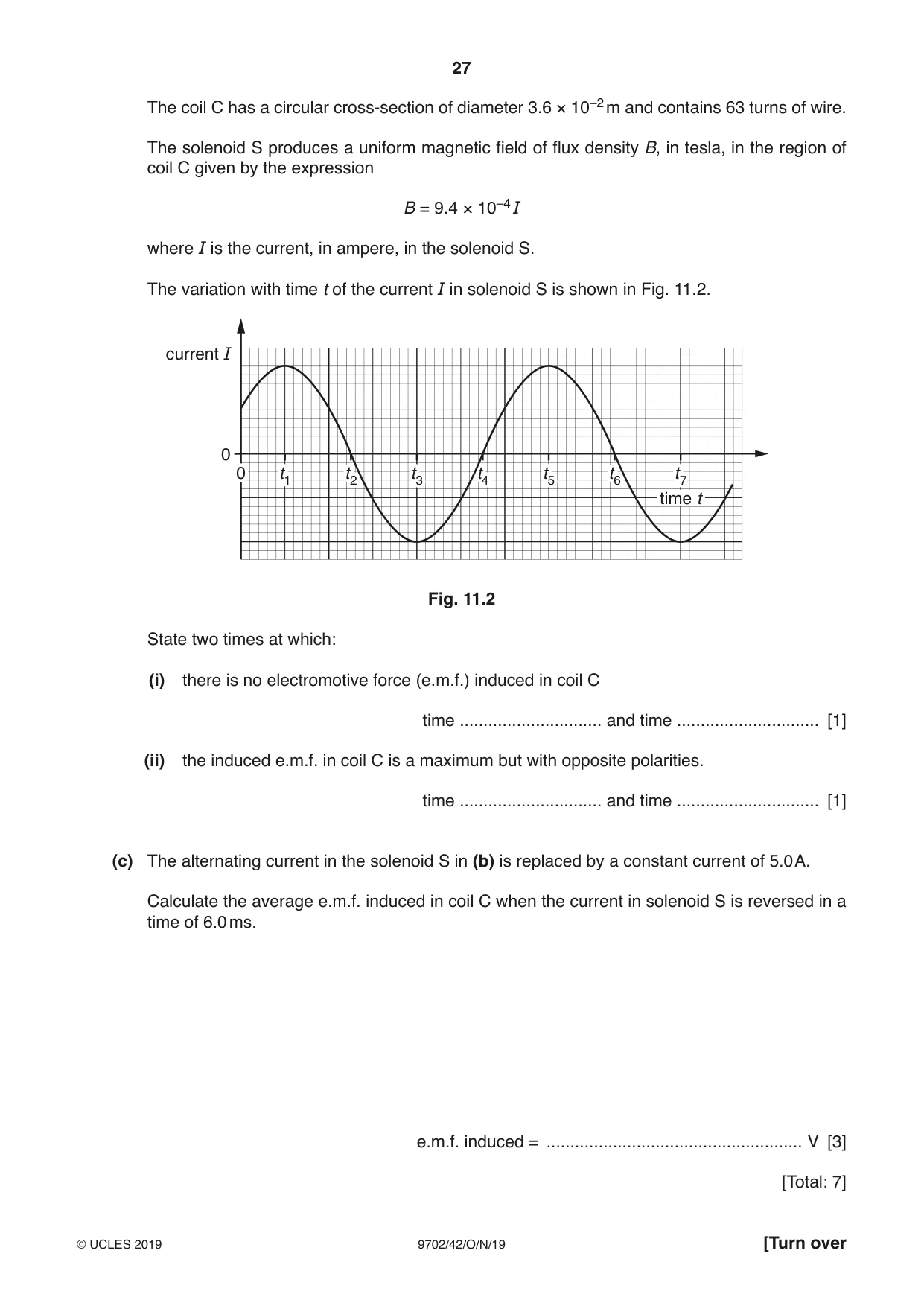
11 (a) State Faraday’s law of electromagnetic induction. ................................................................................................................................................... ................................................................................................................................................... ............................................................................................................................................. [2] (b) A solenoid S has a small coil C placed near to one of its ends, as shown in Fig. 11.1. solenoid S 3.6 × 10⁻² m coil C 63 turns Fig. 11.1 The coil C has a circular cross-section of diameter 3.6 × 10⁻² m and contains 63 turns of wire. The solenoid S produces a uniform magnetic field of flux density B, in tesla, in the region of coil C given by the expression B = 9.4 × 10⁻⁴ I where I is the current, in ampere, in the solenoid S. The variation with time t of the current I in solenoid S is shown in Fig. 11.2. current I 0 0 t1 t2 t3 t4 t5 t6 t7 time t Fig. 11.2 State two times at which: (i) there is no electromotive force (e.m.f.) induced in coil C time .............................. and time .............................. [1] (ii) the induced e.m.f. in coil C is a maximum but with opposite polarities. time .............................. and time .............................. [1] (c) The alternating current in the solenoid S in (b) is replaced by a constant current of 5.0 A. Calculate the average e.m.f. induced in coil C when the current in solenoid S is reversed in a time of 6.0 ms. e.m.f. induced = ...................................................... V [3] [Total: 7]
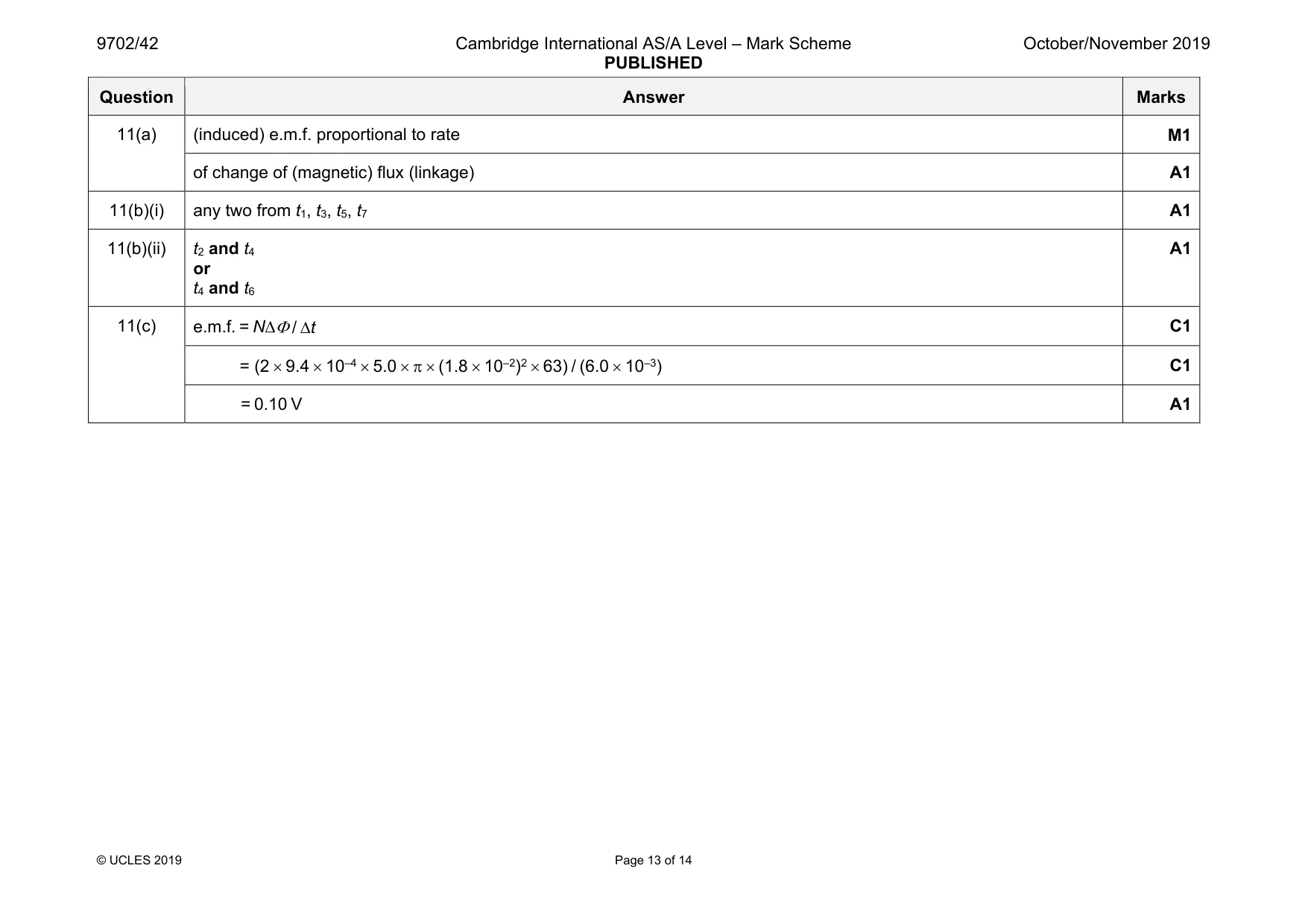
Mark scheme: 11(a) (induced) e.m.f. proportional to rate M1 of change of (magnetic) flux (linkage) A1 11(b)(i) any two from t1, t3, t5, t7 A1 11(b)(ii) t2 and t4 or t4 and t6 A1 11(c) e.m.f. = N∆Φ / ∆t C1 = (2 × 9.4 × 10–4 × 5.0 × π × (1.8 × 10⁻²)2 × 63) / (6.0 × 10⁻³) C1 = 0.10 V A1
Q12 · Radon-222 (22286 Ra) is a radioactive gas that decays randomly with a decay constant of…
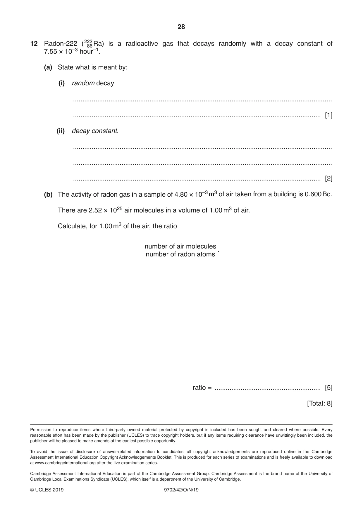
12 Radon-222 (22286 Ra) is a radioactive gas that decays randomly with a decay constant of 7.55 × 10⁻³ hour–1. (a) State what is meant by: (i) random decay ........................................................................................................................................... ..................................................................................................................................... [1] (ii) decay constant. ........................................................................................................................................... ........................................................................................................................................... ..................................................................................................................................... [2] (b) The activity of radon gas in a sample of 4.80 × 10⁻³ m3 of air taken from a building is 0.600 Bq. There are 2.52 × 1025 air molecules in a volume of 1.00 m3 of air. Calculate, for 1.00 m3 of the air, the ratio number of air molecules . number of radon atoms ratio = ......................................................... [5] [Total: 8]
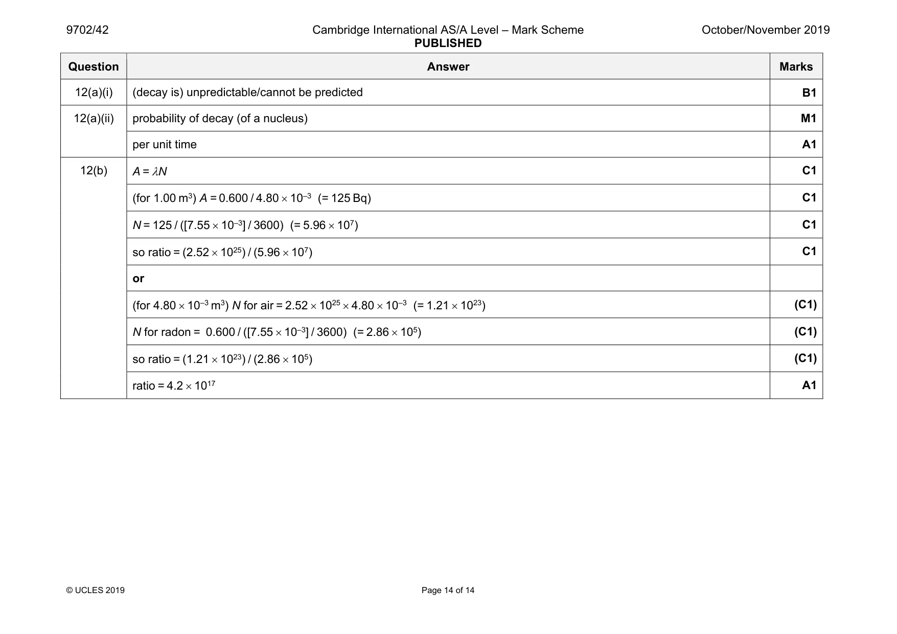
Mark scheme: 12(a)(i) (decay is) unpredictable/cannot be predicted B1 12(a)(ii) probability of decay (of a nucleus) M1 per unit time A1 12(b) A = λN C1 (for 1.00 m3) A = 0.600 / 4.80 × 10⁻³ (= 125 Bq) C1 N = 125 / ([7.55 × 10⁻³] / 3600) (= 5.96 × 10⁷) C1 so ratio = (2.52 × 1025) / (5.96 × 10⁷) C1 or (for 4.80 × 10⁻³ m3) N for air = 2.52 × 1025 × 4.80 × 10–3 (= 1.21 × 10²³) (C1) N for radon = 0.600 / ([7.55 × 10⁻³] / 3600) (= 2.86 × 10⁵) (C1) so ratio = (1.21 × 10²³) / (2.86 × 10⁵) (C1) ratio = 4.2 × 10¹⁷ A1
What was in this paper
The subtopics covered by these 12 questions, and how many questions each got. Open one in a new tab to see every Cambridge question on it.
1Electric force between point charges1Electromagnetic induction1Force on a moving charge1Gravitational force between point masses1Kinetic theory of gases1Potential dividers1Production and use of ultrasound1Production and use of X-rays1Progressive waves1Radioactive decay1Specific heat capacity and specific latent heat1What you needed in this session
Cambridge’s own grade thresholds for 2019 Oct/Nov, Paper 4 · Variant 2. A higher threshold means an easier paper — the bar moves with how the cohort did.