Questions as text
Q1 · A simple test circuit for testing different materials to see how well they conduct… 0653/31 May/June 2017
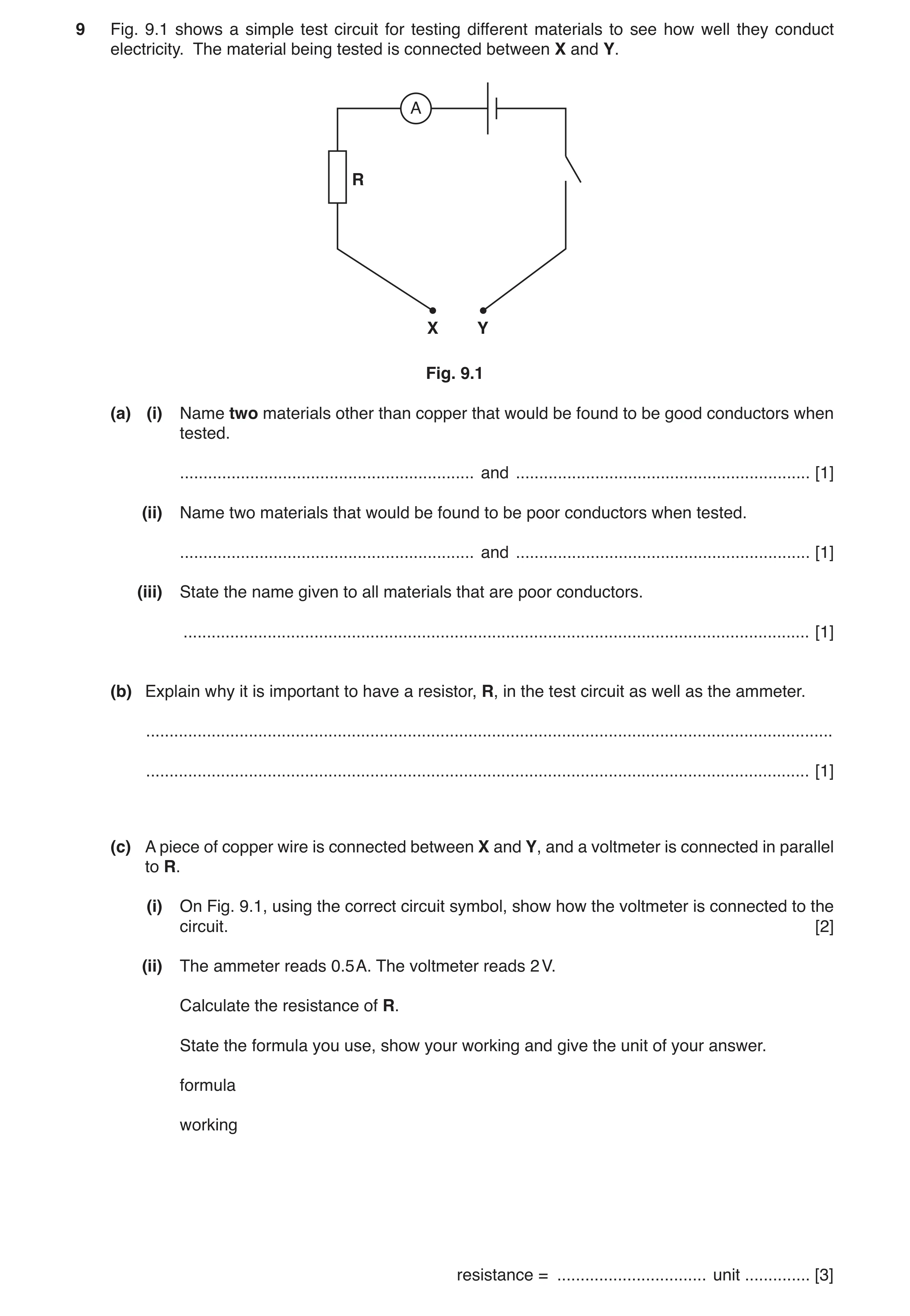
9 Fig. 9.1 shows a simple test circuit for testing different materials to see how well they conduct electricity. The material being tested is connected between X and Y. A R X Y Fig. 9.1 (a) (i) Name two materials other than copper that would be found to be good conductors when tested. … and … [1] (ii) Name two materials that would be found to be poor conductors when tested. … and … [1] (iii) State the name given to all materials that are poor conductors. … [1] (b) Explain why it is important to have a resistor, R, in the test circuit as well as the ammeter. … … [1] (c) A piece of copper wire is connected between X and Y, and a voltmeter is connected in parallel to R. (i) On Fig. 9.1, using the correct circuit symbol, show how the voltmeter is connected to the circuit. [2] (ii) The ammeter reads 0.5 A. The voltmeter reads 2 V. Calculate the resistance of R. State the formula you use, show your working and give the unit of your answer. formula working resistance = … unit … [3]
9 marks
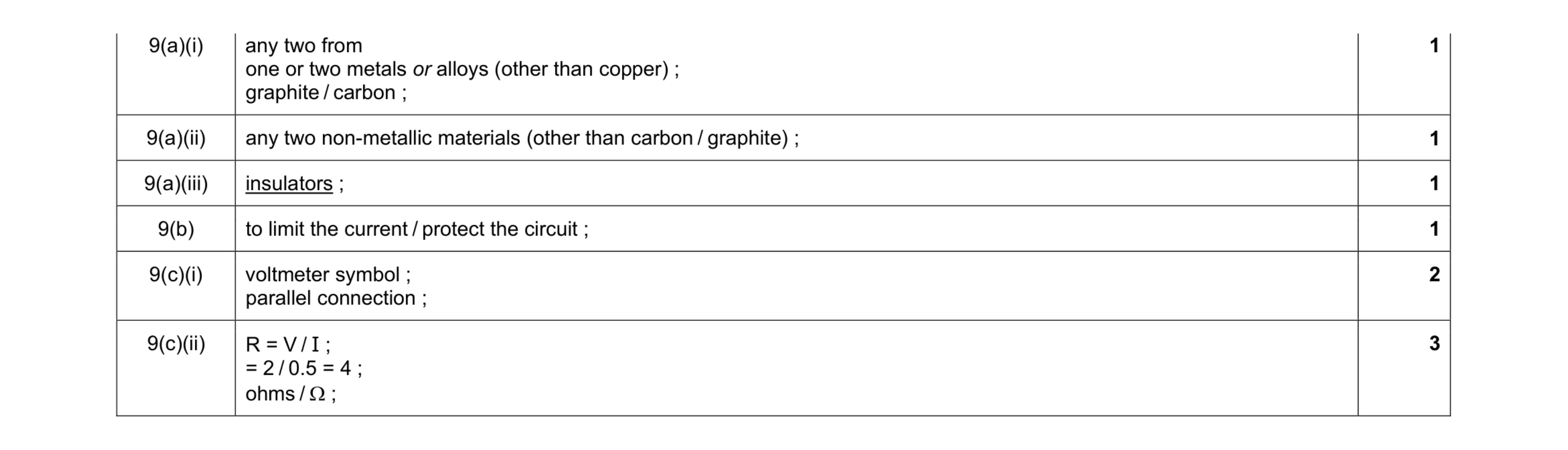
Mark scheme: 9(a)(i) any two from one or two metals or alloys (other than copper) ; graphite / carbon ; 1 9(a)(ii) any two non-metallic materials (other than carbon / graphite) ; 1 9(a)(iii) insulators ; 1 9(b) to limit the current / protect the circuit ; 1 9(c)(i) voltmeter symbol ; parallel connection ; 2 9(c)(ii) R = V / I ; = 2 / 0.5 = 4 ; ohms / Ω ; 3
This question in 0653/31 May/June 2017
Q2 · A simple circuit set up to investigate the electrical properties of a lamp 0653/33 May/June 2017
9 Fig. 9.1 shows a simple circuit set up to investigate the electrical properties of a lamp. cells 0 1 A switch ammeter lamps variable resistor Fig. 9.1 (a) On Fig. 9.2 use the correct circuit symbols to complete the circuit diagram for the circuit shown in Fig. 9.1. Fig. 9.2 [3] (b) The two lamps in the circuit are identical. A voltmeter connected across the two lamps reads 2.4 V. The ammeter reads 0.6 A. Calculate the resistance of one lamp. State the formula used and show your working. formula working resistance = … Ω [3] (c) The resistance of the variable resistor is reduced. State the effect this will have on the brightness of the two lamps. Give a reason for your answer. … … … [1]
7 marks
Mark scheme: 9(a) correct symbols for ammeter and lamp ; correct symbol for variable resistor ; all shown components connected in series, any order ; 3 9(b) resistance = V / I ; (total resistance) = 2.4 / 0.6 (= 4 Ω) ; resistance of one lamp = 2 (Ω) ; 3 9(c) (increase – no mark) (total resistance less) so current increases ; 1
This question in 0653/33 May/June 2017
Q3 · A radiator which uses hot water to provide heating for people sitting in a room watching… 0653/32 Oct/Nov 2017
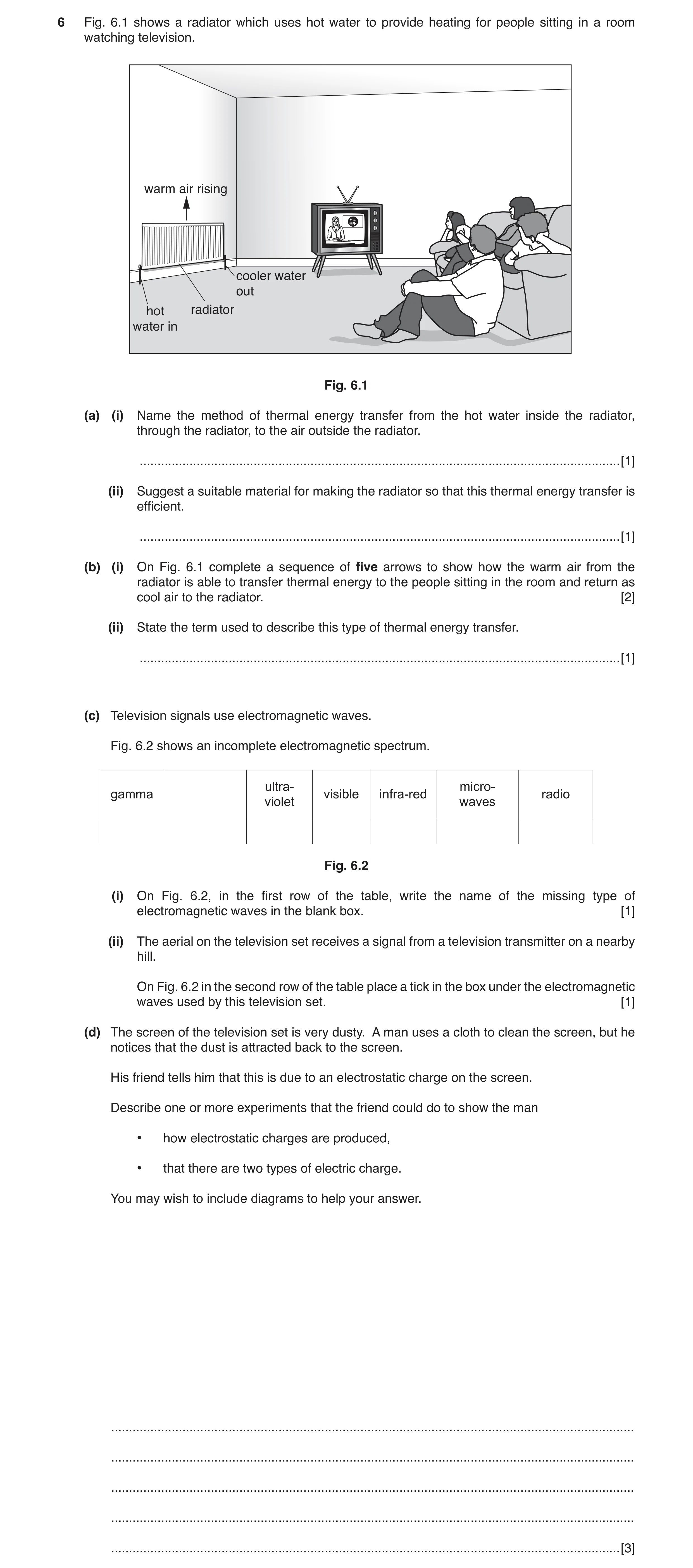
6 Fig. 6.1 shows a radiator which uses hot water to provide heating for people sitting in a room watching television. warm air rising cooler water out hot radiator water in Fig. 6.1 (a) (i) Name the method of thermal energy transfer from the hot water inside the radiator, through the radiator, to the air outside the radiator. … [1] (ii) Suggest a suitable material for making the radiator so that this thermal energy transfer is efficient. … [1] (b) (i) On Fig. 6.1 complete a sequence of five arrows to show how the warm air from the radiator is able to transfer thermal energy to the people sitting in the room and return as cool air to the radiator. [2] (ii) State the term used to describe this type of thermal energy transfer. … [1] (c) Television signals use electromagnetic waves. Fig. 6.2 shows an incomplete electromagnetic spectrum. ultra- micro- gamma visible infra-red radio violet waves Fig. 6.2 (i) On Fig. 6.2, in the first row of the table, write the name of the missing type of electromagnetic waves in the blank box. [1] (ii) The aerial on the television set receives a signal from a television transmitter on a nearby hill. On Fig. 6.2 in the second row of the table place a tick in the box under the electromagnetic waves used by this television set. [1] (d) The screen of the television set is very dusty. A man uses a cloth to clean the screen, but he notices that the dust is attracted back to the screen. His friend tells him that this is due to an electrostatic charge on the screen. Describe one or more experiments that the friend could do to show the man • how electrostatic charges are produced, • that there are two types of electric charge. You may wish to include diagrams to help your answer. … … … … … [3]
10 marks
Mark scheme: 6(a)(i) conduction ; 1 6(a)(ii) metal / named metal ; 1 6(b)(i) arrows up and across room ; arrows down and back towards radiator ; 2 6(b)(ii) convection ; 1 6(c)(i) X-rays ; 1 6(c)(ii) tick under radio waves ; 1 6(d) description of charging by friction ; reference to positive and negative charges / opposite charges attract ; some experimental detail ; 3
This question in 0653/32 Oct/Nov 2017
Q4 · A small electric cooker with two hot plates 0653/31 May/June 2018
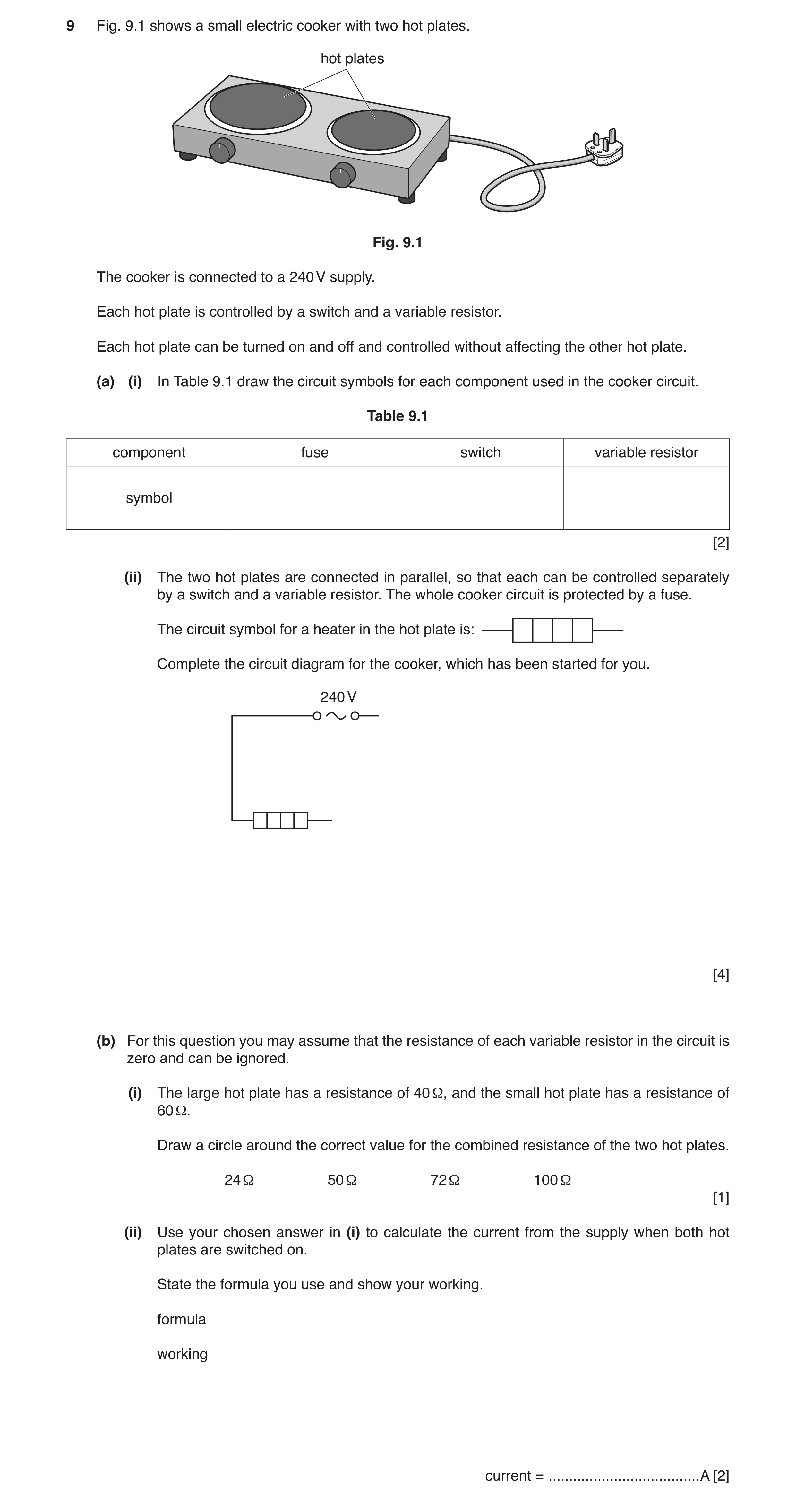
9 Fig. 9.1 shows a small electric cooker with two hot plates. hot plates Fig. 9.1 The cooker is connected to a 240 V supply. Each hot plate is controlled by a switch and a variable resistor. Each hot plate can be turned on and off and controlled without affecting the other hot plate. (a) (i) In Table 9.1 draw the circuit symbols for each component used in the cooker circuit. Table 9.1 component fuse switch variable resistor symbol [2] (ii) The two hot plates are connected in parallel, so that each can be controlled separately by a switch and a variable resistor. The whole cooker circuit is protected by a fuse. The circuit symbol for a heater in the hot plate is: Complete the circuit diagram for the cooker, which has been started for you. 240 V [4] (b) For this question you may assume that the resistance of each variable resistor in the circuit is zero and can be ignored. (i) The large hot plate has a resistance of 40 Ω, and the small hot plate has a resistance of 60 Ω. Draw a circle around the correct value for the combined resistance of the two hot plates. 24 Ω 50 Ω 72 Ω 100 Ω [1] (ii) Use your chosen answer in (i) to calculate the current from the supply when both hot plates are switched on. State the formula you use and show your working. formula working current = … A [2]
9 marks
Mark scheme: 9 9 9(a)(i) fuse: switc varia three one o 9(a)(ii) seco each each fuse 9(b)(i) 24 Ω 9(b)(ii) R = V I = 1 ch: able resistor: e correct symbol or two correct sy nd hotplate con hotplate branch hotplate branch in main circuit ; ; V / I or 24 = 240 0A ; s for 2 marks ; ymbols for 1 ma nected in paralle h contains a vari h has a switch in / I or I = V / R o rk ; el ; iable resistor in n series ; or I = 240 / 24 ; series ; 2 4 1 2
This question in 0653/31 May/June 2018
Q5 · A simple circuit set up to investigate the current through an electric motor 0653/33 May/June 2018
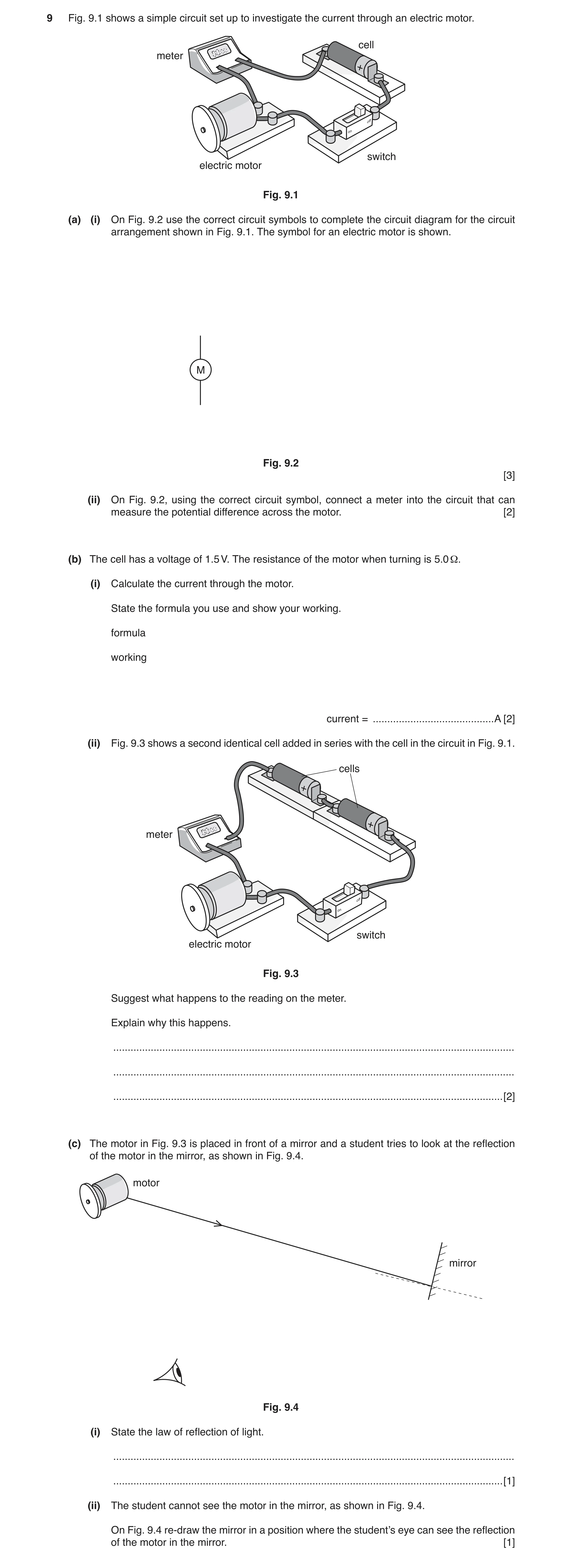
9 Fig. 9.1 shows a simple circuit set up to investigate the current through an electric motor. cell meter + off switch electric motor Fig. 9.1 (a) (i) On Fig. 9.2 use the correct circuit symbols to complete the circuit diagram for the circuit arrangement shown in Fig. 9.1. The symbol for an electric motor is shown. M Fig. 9.2 [3] (ii) On Fig. 9.2, using the correct circuit symbol, connect a meter into the circuit that can measure the potential difference across the motor. [2] (b) The cell has a voltage of 1.5 V. The resistance of the motor when turning is 5.0 Ω. (i) Calculate the current through the motor. State the formula you use and show your working. formula working current = … A [2] (ii) Fig. 9.3 shows a second identical cell added in series with the cell in the circuit in Fig. 9.1. cells + + meter off switch electric motor Fig. 9.3 Suggest what happens to the reading on the meter. Explain why this happens. … … … [2] (c) The motor in Fig. 9.3 is placed in front of a mirror and a student tries to look at the reflection of the motor in the mirror, as shown in Fig. 9.4. motor mirror Fig. 9.4 (i) State the law of reflection of light. … … [1] (ii) The student cannot see the motor in the mirror, as shown in Fig. 9.4. On Fig. 9.4 re‑draw the mirror in a position where the student’s eye can see the reflection of the motor in the mirror. [1]
11 marks
Mark scheme: 9(a)(i) correct symbol for cell ; correct symbol for switch ; meter identified as an ammeter and a complete series circuit connected ; 3 9(a)(ii) correct meter selected (V symbol) ; meter connected in parallel with motor ; 2 9(b)(i) I = V / R or I = 1.5 / 5.0 ; = 0.30 (A) ; 2 Question Answer Marks 9(b)(ii) reading on ammeter increases / current increases ; (extra cell) increases pd / voltage (across motor) ; 2 9(c)(i) angle of incidence = angle of reflection ; 1 9(c)(ii) mirror shown at approx. correct angle ; 1
This question in 0653/33 May/June 2018
Q6 · A display refrigerator for storing cold drinks 0653/33 Oct/Nov 2018
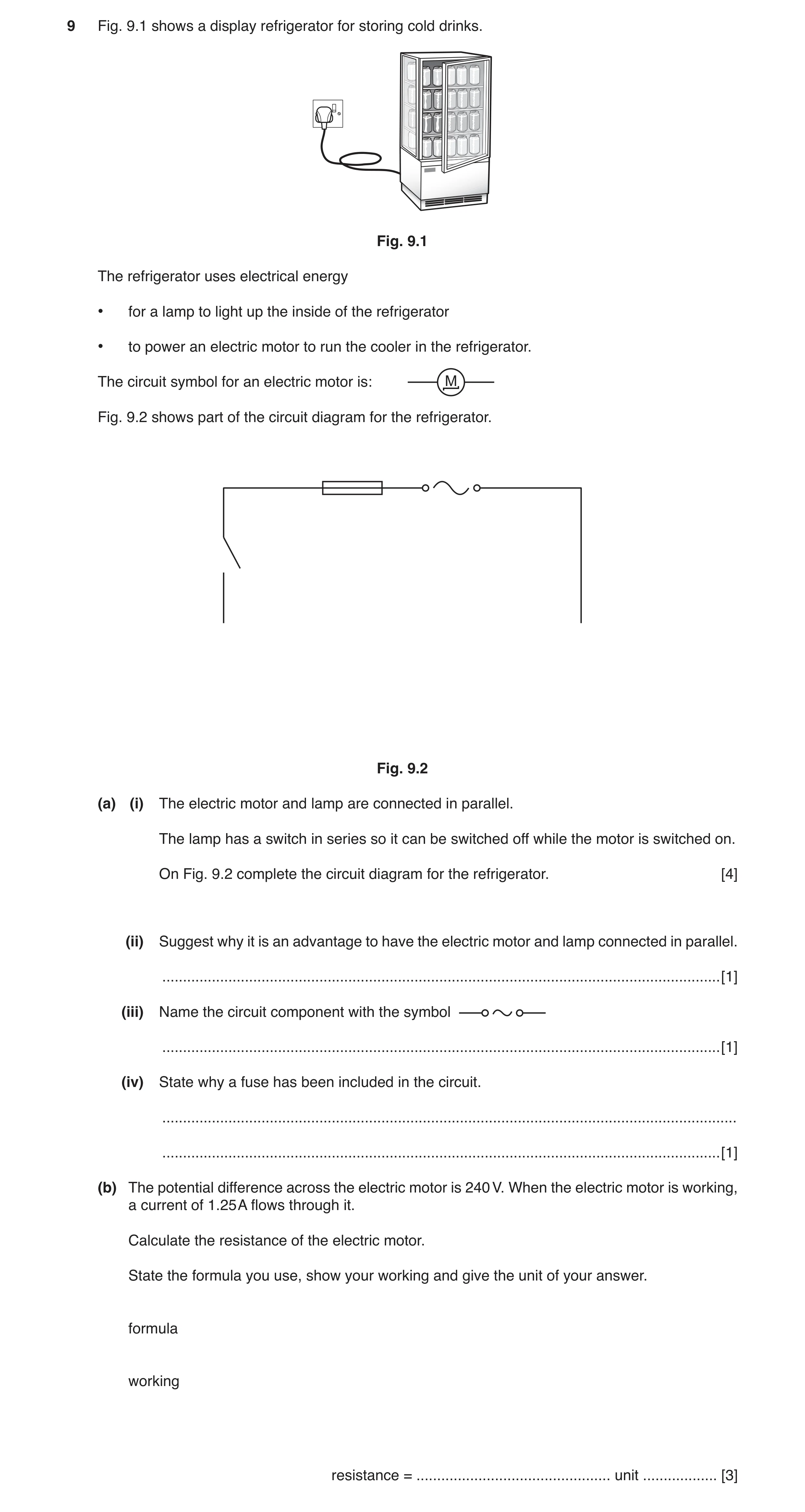
9 Fig. 9.1 shows a display refrigerator for storing cold drinks. Fig. 9.1 The refrigerator uses electrical energy • for a lamp to light up the inside of the refrigerator • to power an electric motor to run the cooler in the refrigerator. The circuit symbol for an electric motor is: M Fig. 9.2 shows part of the circuit diagram for the refrigerator. Fig. 9.2 (a) (i) The electric motor and lamp are connected in parallel. The lamp has a switch in series so it can be switched off while the motor is switched on. On Fig. 9.2 complete the circuit diagram for the refrigerator. [4] (ii) Suggest why it is an advantage to have the electric motor and lamp connected in parallel. … [1] (iii) Name the circuit component with the symbol … [1] (iv) State why a fuse has been included in the circuit. … … [1] (b) The potential difference across the electric motor is 240 V. When the electric motor is working, a current of 1.25 A flows through it. Calculate the resistance of the electric motor. State the formula you use, show your working and give the unit of your answer. formula working resistance = … unit … [3]
10 marks
Mark scheme: 9(a)(i) correct symbol for lamp ; parallel circuit with motor in one branch, lamp in other branch ; switch in series with lamp only ; complete workable circuit ; 4 9(a)(ii) lamp can be switched off while motor remains on / if one component fails, the other will still work ; 1 9(a)(iii) mains supply / (a.c.) power supply ; 1 9(a)(iv) protection of components / circuit / wiring from excess current / overheating ; 1 9(b) R (= V / I) / 240 / 1.25 ; = 192 ; Ω / ohm ; 3
This question in 0653/33 Oct/Nov 2018
Q7 · In many cities, sodium street lamps are used at night 0653/32 Feb/March 2019
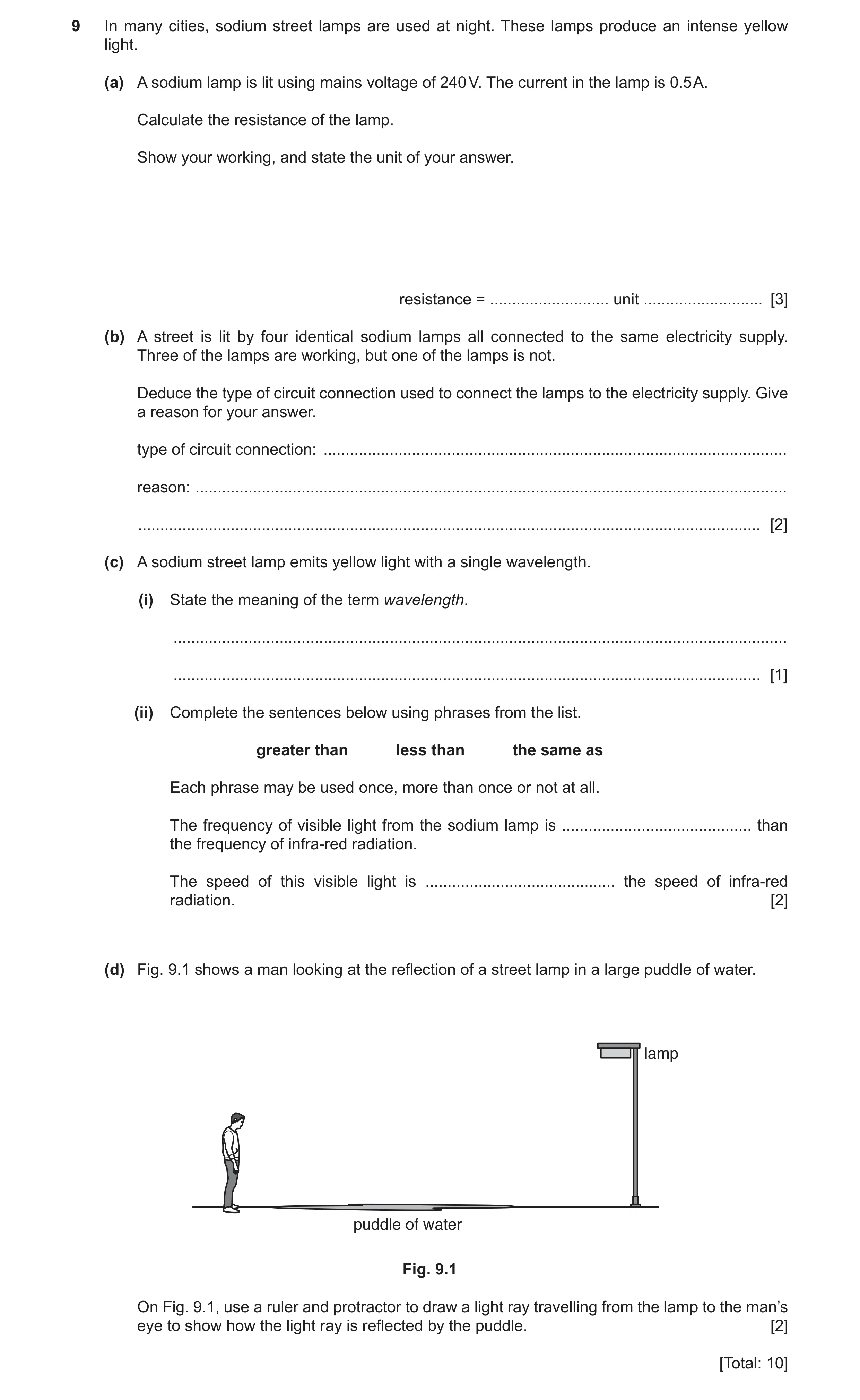
9 In many cities, sodium street lamps are used at night. These lamps produce an intense yellow light. (a) A sodium lamp is lit using mains voltage of 240 V. The current in the lamp is 0.5 A. Calculate the resistance of the lamp. Show your working, and state the unit of your answer. resistance = … unit … [3] (b) A street is lit by four identical sodium lamps all connected to the same electricity supply. Three of the lamps are working, but one of the lamps is not. Deduce the type of circuit connection used to connect the lamps to the electricity supply. Give a reason for your answer. type of circuit connection: … reason: … … [2] (c) A sodium street lamp emits yellow light with a single wavelength. (i) State the meaning of the term wavelength. … … [1] (ii) Complete the sentences below using phrases from the list. greater than less than the same as Each phrase may be used once, more than once or not at all. The frequency of visible light from the sodium lamp is … than the frequency of infra-red radiation. The speed of this visible light is … the speed of infra-red radiation. [2] (d) Fig. 9.1 shows a man looking at the reflection of a street lamp in a large puddle of water. lamp puddle of water Fig. 9.1 On Fig. 9.1, use a ruler and protractor to draw a light ray travelling from the lamp to the man’s eye to show how the light ray is reflected by the puddle. [2] [Total: 10]
10 marks
Mark scheme: 9(a) = 480 ; ohms / Ω ; 3 9(b) parallel ; if in series, all lamps would have gone out / lamp not working means a break in circuit / if in parallel there is still a complete circuit if one lamp goes out ; 2 Question Answer Marks 9(c)(i) distance between two successive crests / troughs ; 1 9(c)(ii) greater than ; the same as ; 2 9(d) incident ray and reflected ray both drawn with arrows ; angle of incidence and angle of reflection equal, judged by eye ; 2
This question in 0653/32 Feb/March 2019
Q8 · A lightning flash, which is a form of electrostatic discharge 0653/32 Oct/Nov 2019
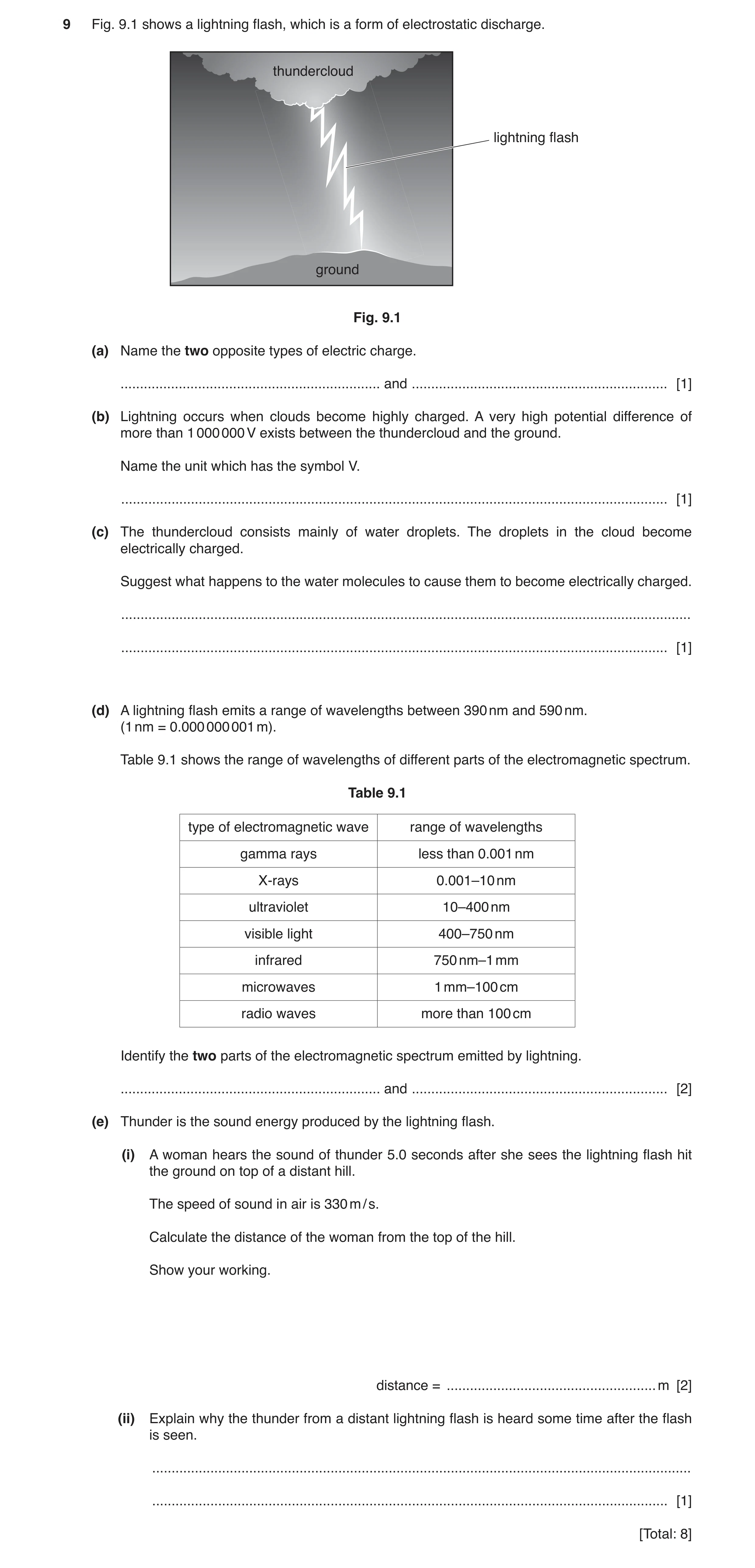
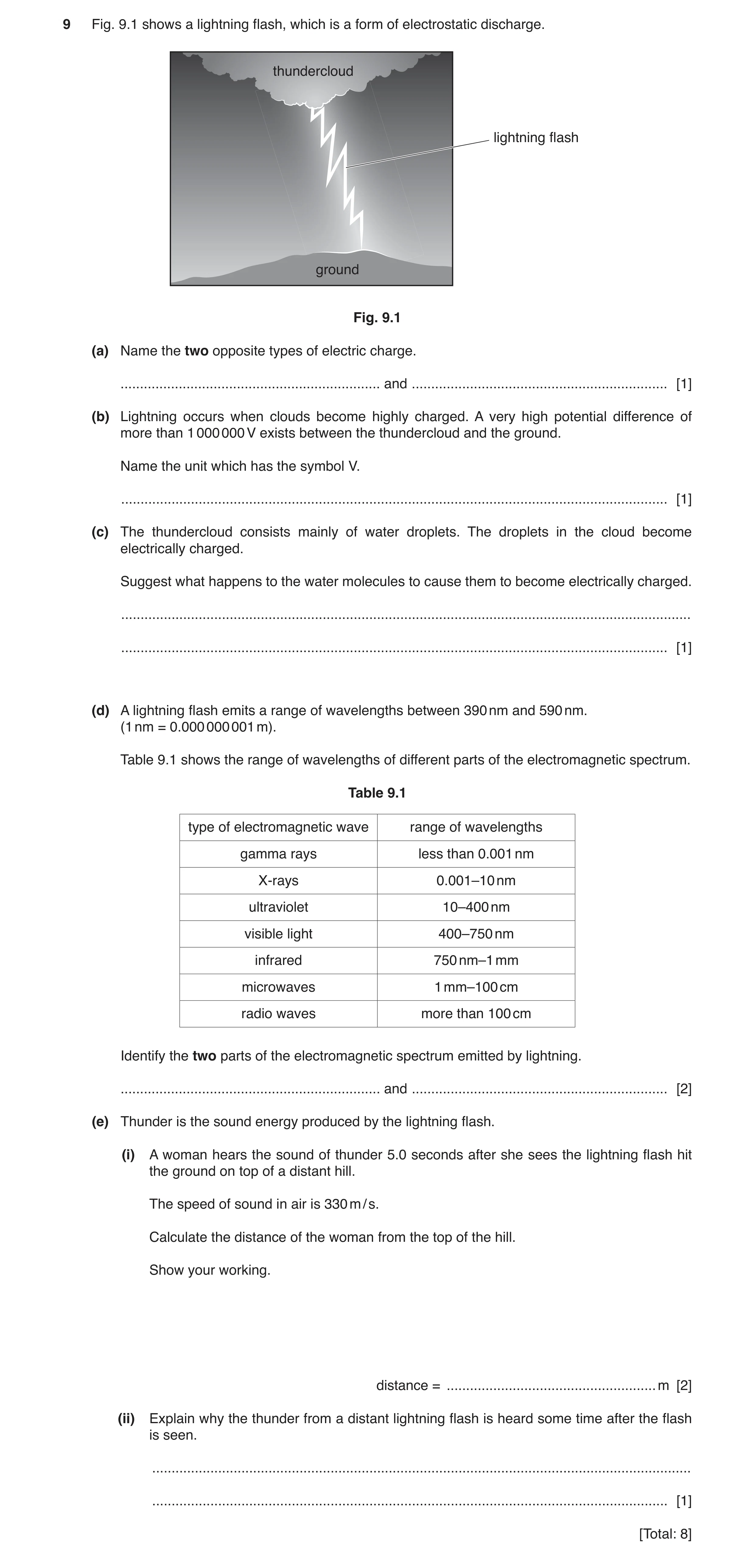
9 Fig. 9.1 shows a lightning flash, which is a form of electrostatic discharge. thundercloud lightning flash ground Fig. 9.1 (a) Name the two opposite types of electric charge. … and … [1] (b) Lightning occurs when clouds become highly charged. A very high potential difference of more than 1 000 000 V exists between the thundercloud and the ground. Name the unit which has the symbol V. … [1] (c) The thundercloud consists mainly of water droplets. The droplets in the cloud become electrically charged. Suggest what happens to the water molecules to cause them to become electrically charged. … … [1] (d) A lightning flash emits a range of wavelengths between 390 nm and 590 nm. (1 nm = 0.000 000 001 m). Table 9.1 shows the range of wavelengths of different parts of the electromagnetic spectrum. Table 9.1 type of electromagnetic wave range of wavelengths gamma rays less than 0.001 nm X‑rays 0.001–10 nm ultraviolet 10–400 nm visible light 400–750 nm infrared 750 nm–1 mm microwaves 1 mm–100 cm radio waves more than 100 cm Identify the two parts of the electromagnetic spectrum emitted by lightning. … and … [2] (e) Thunder is the sound energy produced by the lightning flash. (i) A woman hears the sound of thunder 5.0 seconds after she sees the lightning flash hit the ground on top of a distant hill. The speed of sound in air is 330 m / s. Calculate the distance of the woman from the top of the hill. Show your working. distance = … m [2] (ii) Explain why the thunder from a distant lightning flash is heard some time after the flash is seen. … … [1] [Total: 8]
8 marks
Mark scheme: 9(a) positive and negative ; 1 9(b) volt(s); 1 9(c) loss / gain / transfer of electrons (between molecules) ; 1 9(d) visible light; ultraviolet ; 2 9(e)(i) speed = distance / time or d = speed × time = 330 × 5.0 ; = 1650 (m) ; 2 9(e)(ii) light travels (much) faster than sound ; 1
This question in 0653/32 Oct/Nov 2019
Q9 · An electric hair dryer 0653/33 Oct/Nov 2019
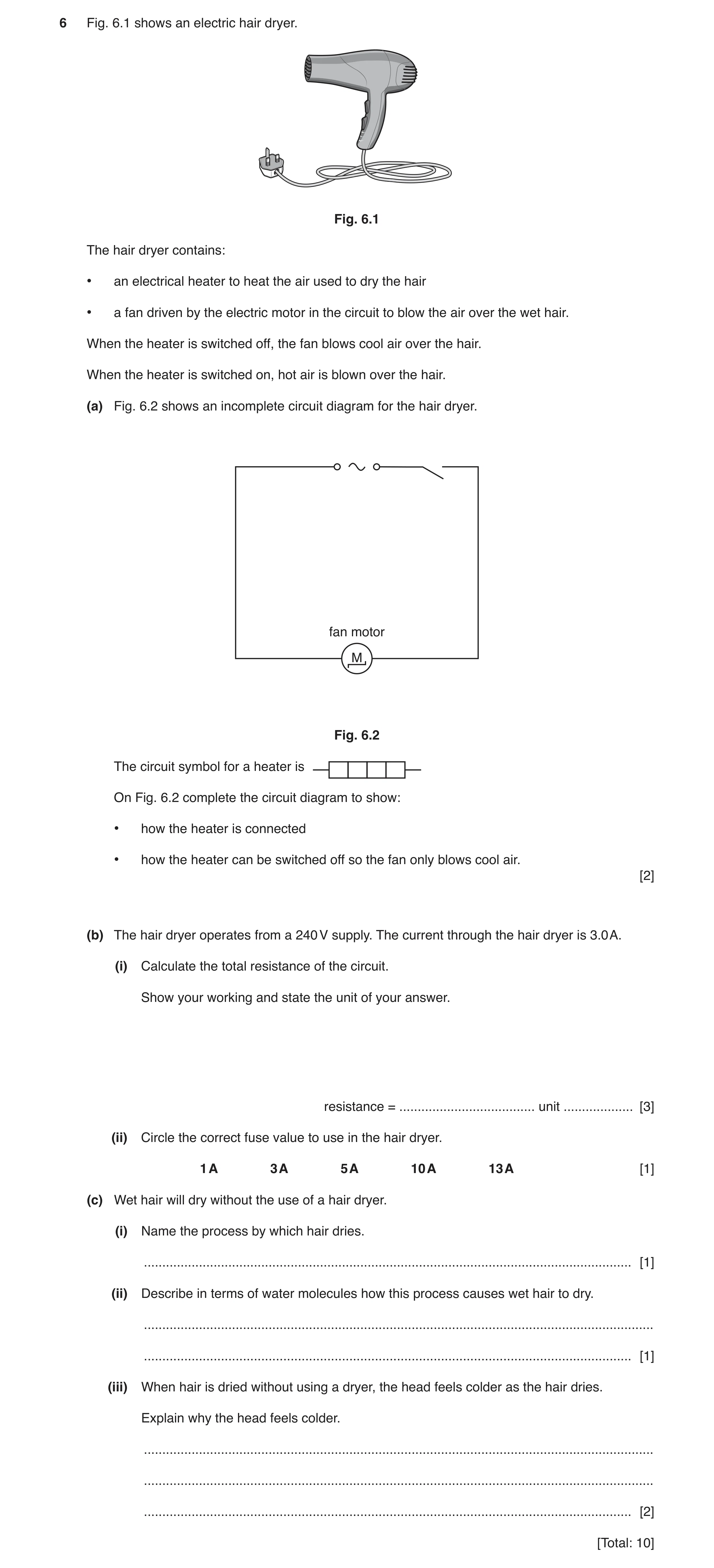
6 Fig. 6.1 shows an electric hair dryer. Fig. 6.1 The hair dryer contains: • an electrical heater to heat the air used to dry the hair • a fan driven by the electric motor in the circuit to blow the air over the wet hair. When the heater is switched off, the fan blows cool air over the hair. When the heater is switched on, hot air is blown over the hair. (a) Fig. 6.2 shows an incomplete circuit diagram for the hair dryer. fan motor M Fig. 6.2 The circuit symbol for a heater is On Fig. 6.2 complete the circuit diagram to show: • how the heater is connected • how the heater can be switched off so the fan only blows cool air. [2] (b) The hair dryer operates from a 240 V supply. The current through the hair dryer is 3.0 A. (i) Calculate the total resistance of the circuit. Show your working and state the unit of your answer. resistance = … unit … [3] (ii) Circle the correct fuse value to use in the hair dryer. 1 A 3 A 5 A 10 A 13 A [1] (c) Wet hair will dry without the use of a hair dryer. (i) Name the process by which hair dries. … [1] (ii) Describe in terms of water molecules how this process causes wet hair to dry. … … [1] (iii) When hair is dried without using a dryer, the head feels colder as the hair dries. Explain why the head feels colder. … … … [2] [Total: 10]
10 marks
Mark scheme: 6(a) 2 6(b)(i) use of R = V / I or R = 240 / 3 ; = 80 ; Ω / ohm(s) ; 3 6(b)(ii) 5 A ; 1 6(c)(i) evaporation ; 1 6(c)(ii) escape of faster (water) molecules ; 1 6(c)(iii) any two from: thermal energy transferred from body (to water molecules) ; remaining molecules slower (on average) ; slower molecules means lower temperature ; 2 heater inserted in a parallel branch ; second switch in series with heater in same branch ;
This question in 0653/33 Oct/Nov 2019
Q10 · A lightning flash, which is a form of electrostatic discharge 0653/33 Oct/Nov 2019
9 Fig. 9.1 shows a lightning flash, which is a form of electrostatic discharge. thundercloud lightning flash ground Fig. 9.1 (a) Name the two opposite types of electric charge. … and … [1] (b) Lightning occurs when clouds become highly charged. A very high potential difference of more than 1 000 000 V exists between the thundercloud and the ground. Name the unit which has the symbol V. … [1] (c) The thundercloud consists mainly of water droplets. The droplets in the cloud become electrically charged. Suggest what happens to the water molecules to cause them to become electrically charged. … … [1] (d) A lightning flash emits a range of wavelengths between 390 nm and 590 nm. (1 nm = 0.000 000 001 m). Table 9.1 shows the range of wavelengths of different parts of the electromagnetic spectrum. Table 9.1 type of electromagnetic wave range of wavelengths gamma rays less than 0.001 nm X‑rays 0.001–10 nm ultraviolet 10–400 nm visible light 400–750 nm infrared 750 nm–1 mm microwaves 1 mm–100 cm radio waves more than 100 cm Identify the two parts of the electromagnetic spectrum emitted by lightning. … and … [2] (e) Thunder is the sound energy produced by the lightning flash. (i) A woman hears the sound of thunder 5.0 seconds after she sees the lightning flash hit the ground on top of a distant hill. The speed of sound in air is 330 m / s. Calculate the distance of the woman from the top of the hill. Show your working. distance = … m [2] (ii) Explain why the thunder from a distant lightning flash is heard some time after the flash is seen. … … [1] [Total: 8]
8 marks
Mark scheme: 9(a) positive and negative ; 1 9(b) volt(s); 1 9(c) loss / gain / transfer of electrons (between molecules) ; 1 9(d) visible light; ultraviolet ; 2 9(e)(i) speed = distance / time or d = speed × time = 330 × 5.0 ; = 1650 (m) ; 2 9(e)(ii) light travels (much) faster than sound ; 1
This question in 0653/33 Oct/Nov 2019
Question 11 0653/32 Feb/March 2020
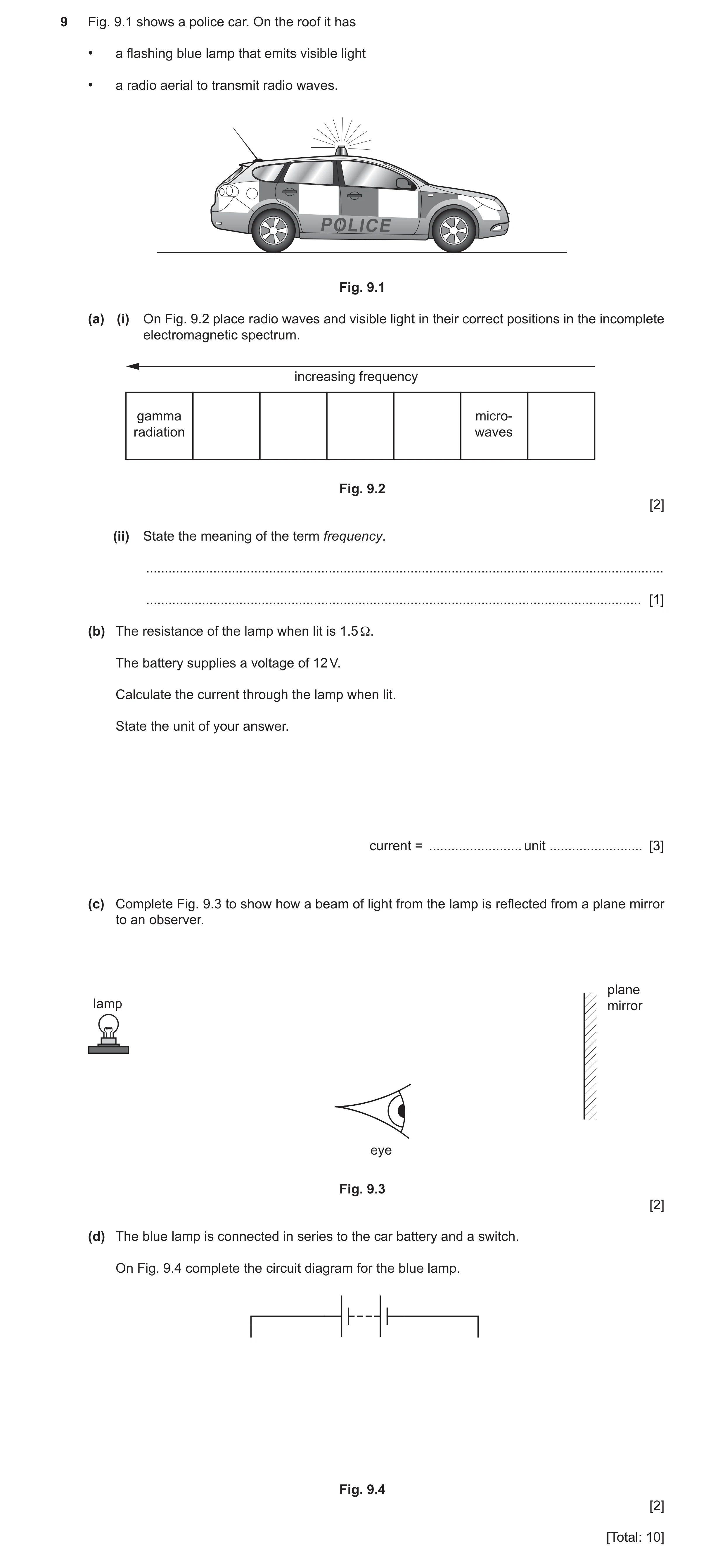
9 Fig. 9.1 shows a police car. On the roof it has • a flashing blue lamp that emits visible light • a radio aerial to transmit radio waves. P O L I C E Fig. 9.1 (a) (i) On Fig. 9.2 place radio waves and visible light in their correct positions in the incomplete electromagnetic spectrum. increasing frequency gamma micro- radiation waves Fig. 9.2 [2] (ii) State the meaning of the term frequency. … … [1] (b) The resistance of the lamp when lit is 1.5 Ω. The battery supplies a voltage of 12 V. Calculate the current through the lamp when lit. State the unit of your answer. current = … unit … [3] (c) Complete Fig. 9.3 to show how a beam of light from the lamp is reflected from a plane mirror to an observer. plane lamp mirror eye Fig. 9.3 [2] (d) The blue lamp is connected in series to the car battery and a switch. On Fig. 9.4 complete the circuit diagram for the blue lamp. Fig. 9.4 [2] [Total: 10]
10 marks
Mark scheme: 9(a)(i) gamma radiation (visible) light ; micro- waves radio waves ; 2 9(a)(ii) number of, vibrations / waves / oscillations per second ; 1 9(b) R = V / I or I = V / R = 12 / 1.5 ; = 8 ; (unit =) A ; 3 Question Answer Marks 9(c) 2 9(d) 2 ray from lamp to mirror to eye ; angle of incidence and angle of reflection at mirror judged by eye to be equal (normal not required) ; correct symbols for lamp and switch ; complete series circuit with no additional components ;
This question in 0653/32 Feb/March 2020
Q12 · The front door of a house has an electric bell and a lamp 0653/32 Oct/Nov 2020
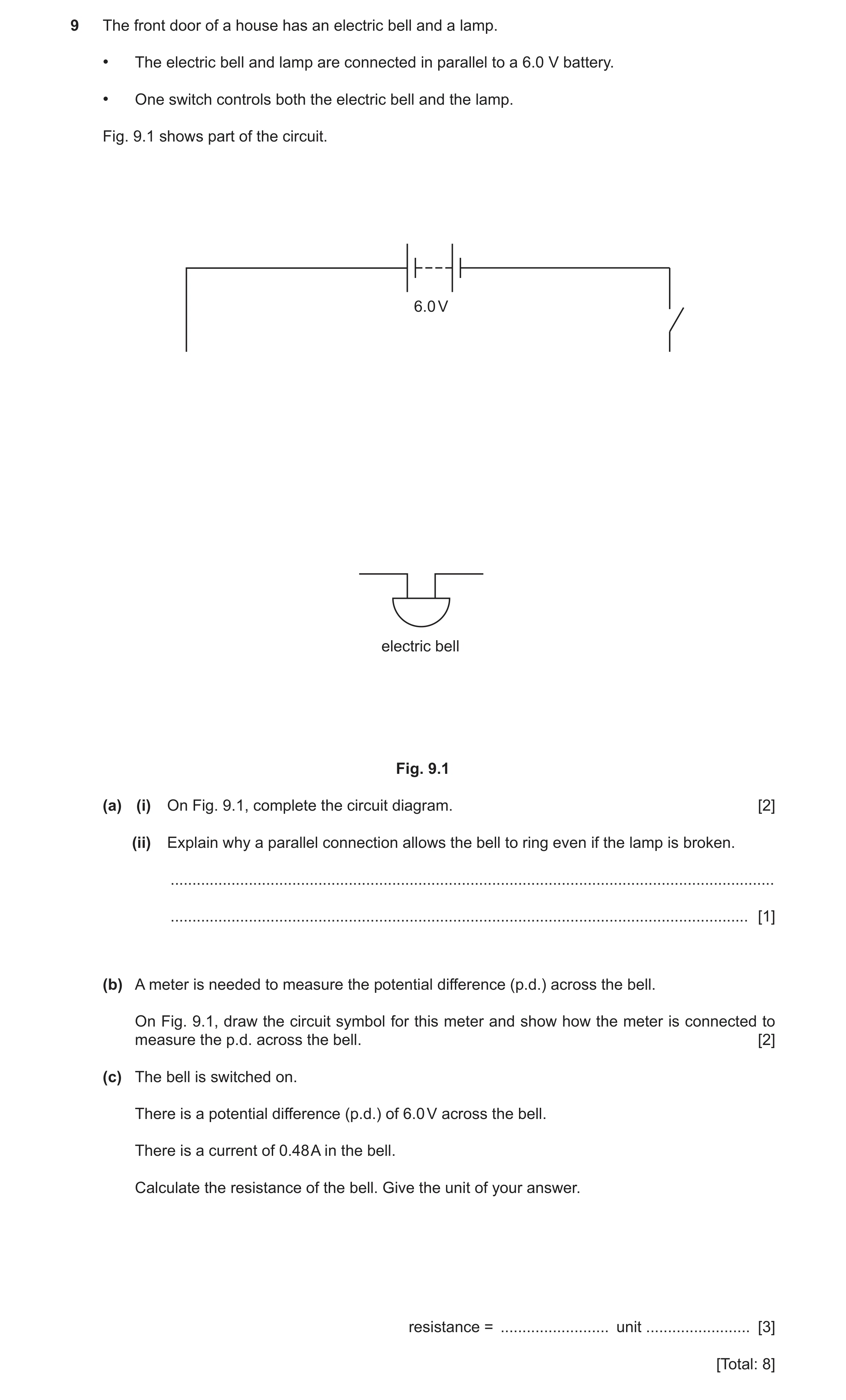
9 The front door of a house has an electric bell and a lamp. • The electric bell and lamp are connected in parallel to a 6.0 V battery. • One switch controls both the electric bell and the lamp. Fig. 9.1 shows part of the circuit. 6.0 V electric bell Fig. 9.1 (a) (i) On Fig. 9.1, complete the circuit diagram. [2] (ii) Explain why a parallel connection allows the bell to ring even if the lamp is broken. … … [1] (b) A meter is needed to measure the potential difference (p.d.) across the bell. On Fig. 9.1, draw the circuit symbol for this meter and show how the meter is connected to measure the p.d. across the bell. [2] (c) The bell is switched on. There is a potential difference (p.d.) of 6.0 V across the bell. There is a current of 0.48 A in the bell. Calculate the resistance of the bell. Give the unit of your answer. resistance = … unit … [3] [Total: 8]
8 marks
Mark scheme: 9(a)(i) lamp symbol ; parallel connection and complete circuit ; 2 9(a)(ii) still a complete circuit (through bell branch) ; 1 9(b) voltmeter symbol ; connected in parallel to bell (above or below) ; 2 9(c) R = V÷I in any form / 6.0 ÷ 0.48 ; 12.5 ; Ω / ohm(s) ; 3
This question in 0653/32 Oct/Nov 2020
Q13 · In the box in Fig 0653/33 Oct/Nov 2020
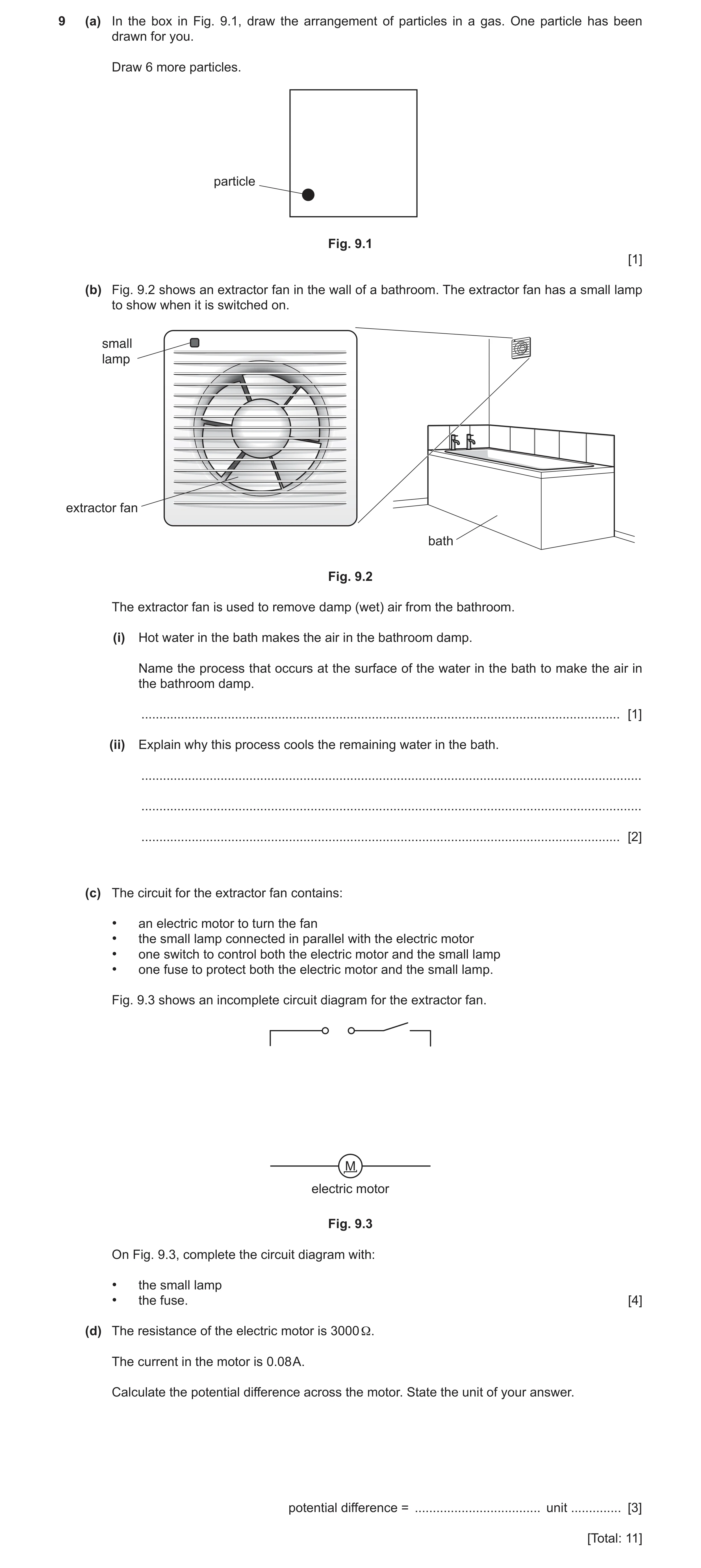
9 (a) In the box in Fig. 9.1, draw the arrangement of particles in a gas. One particle has been drawn for you. Draw 6 more particles. particle Fig. 9.1 [1] (b) Fig. 9.2 shows an extractor fan in the wall of a bathroom. The extractor fan has a small lamp to show when it is switched on. small lamp extractor fan bath Fig. 9.2 The extractor fan is used to remove damp (wet) air from the bathroom. (i) Hot water in the bath makes the air in the bathroom damp. Name the process that occurs at the surface of the water in the bath to make the air in the bathroom damp. … [1] (ii) Explain why this process cools the remaining water in the bath. … … … [2] (c) The circuit for the extractor fan contains: • an electric motor to turn the fan • the small lamp connected in parallel with the electric motor • one switch to control both the electric motor and the small lamp • one fuse to protect both the electric motor and the small lamp. Fig. 9.3 shows an incomplete circuit diagram for the extractor fan. M electric motor Fig. 9.3 On Fig. 9.3, complete the circuit diagram with: • the small lamp • the fuse. [4] (d) The resistance of the electric motor is 3000 Ω. The current in the motor is 0.08 A. Calculate the potential difference across the motor. State the unit of your answer. potential difference = … unit … [3] [Total: 11]
11 marks
Mark scheme: 9(a) random arrangement of 6 additional particles, far apart ; 1 9(b)(i) evaporation ; 1 9(b)(ii) faster / more-energetic, water molecules escape ; remaining molecules have less energy (so water is cooler) ; 2 9(c) correct symbol for lamp ; correct symbol for fuse ; lamp in parallel with motor ; fuse in main circuit ; 4 9(c) V = IR in any form / 0.080 × 3000 ; 240 ; V / volts ; 3
This question in 0653/33 Oct/Nov 2020
Q14 · State the name of the particles that flow in an electric current in a metal wire 0653/31 May/June 2021
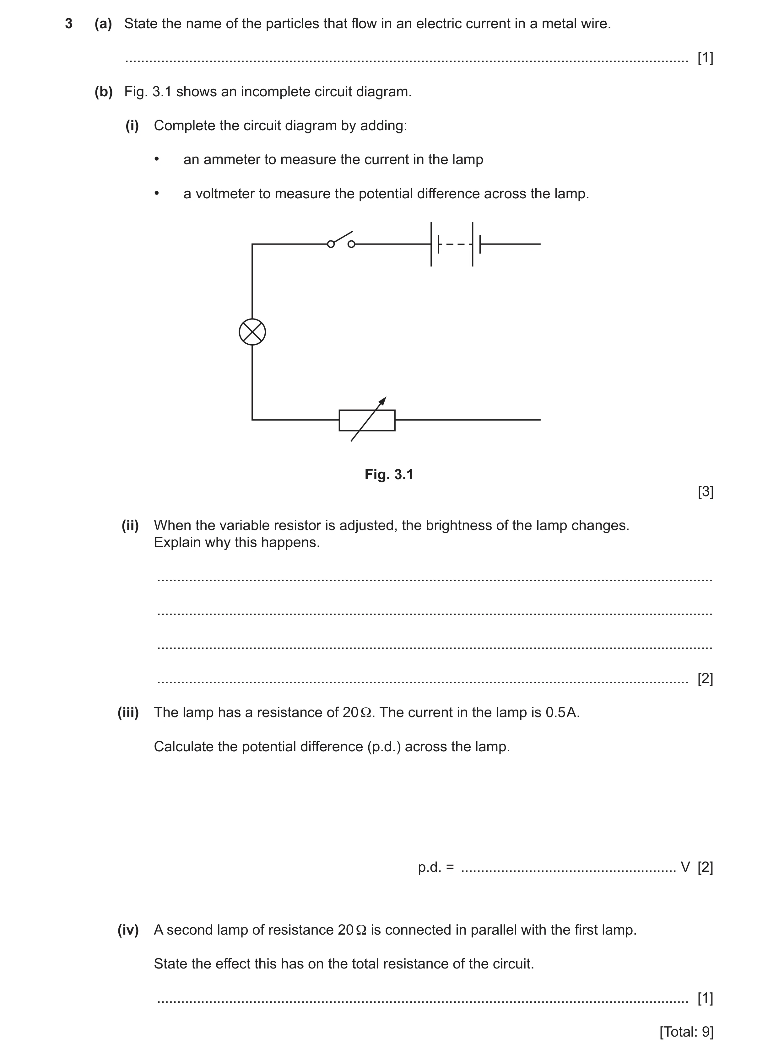
3 (a) State the name of the particles that flow in an electric current in a metal wire. … [1] (b) Fig. 3.1 shows an incomplete circuit diagram. (i) Complete the circuit diagram by adding: • an ammeter to measure the current in the lamp • a voltmeter to measure the potential difference across the lamp. Fig. 3.1 [3] (ii) When the variable resistor is adjusted, the brightness of the lamp changes. Explain why this happens. … … … … [2] (iii) The lamp has a resistance of 20 Ω. The current in the lamp is 0.5 A. Calculate the potential difference (p.d.) across the lamp. p.d. = … V [2] (iv) A second lamp of resistance 20 Ω is connected in parallel with the first lamp. State the effect this has on the total resistance of the circuit. … [1] [Total: 9]
9 marks
Mark scheme: 3(a) electrons ; 1 3(b)(i) M1 ammeter symbol ; M2 voltmeter symbol ; M3 voltmeter in parallel with lamp only in fully correct circuit ; 3 3(b)(ii) (change in resistance) changes current ; more resistance / less current, means dimmer bulb ; 2 3(b)(iii) R = V / I or V = I R / = 0.5 × 20 ; (p.d. =) 10 (V) ; 2 Question Answer Marks 3(b)(iv) decreases / reduces / lowers / gets less ; 1
This question in 0653/31 May/June 2021
Q15 · A cylinder made of solid copper 0653/32 May/June 2021
3 (a) Fig. 3.1 shows a cylinder made of solid copper. Fig. 3.1 The cylinder has a: • height of 25 cm • radius of 10 cm • mass of 70 000 g. (i) Show that the volume of the copper cylinder is 7850 cm3. π = 3.14 [2] (ii) Use the information above to calculate the density of copper in g / cm3. density = … g / cm3 [2] (b) Fig. 3.2 shows two electrically charged copper spheres next to each other. + – + + – – + + – – + + – – + + – – – – + + + – sphere A sphere B Fig. 3.2 (i) State which sphere is charged with an excess of electrons. Give a reason for your answer. sphere … reason … … [1] (ii) On Fig. 3.2 the force arrow shows the direction of the force exerted on sphere A by sphere B. Explain why sphere B exerts this force on sphere A. … … [2] (c) A length of thin copper wire has a resistance of 3 Ω. The potential difference (p.d.) across the wire is 12 V. Calculate the current in the copper wire. State the unit of your answer. current = … unit … [3] [Total: 10]
10 marks
Mark scheme: 3(a)(i) volume of cylinder = πr2 l ; 3.14 × 100 × 25 (= 7850 cm3) ; 3(a)(ii) density = mass ÷ volume / ρ = m ÷ V / = 70 000 ÷ 7850 ; (density =) 8.9(2) (g / cm3) ; 2 3(b)(i) sphere: B (no mark) reason: negatively charged ; 1 3(b)(ii) opposite charges ; attract ; 2 Question Answer Marks 3(c) R = V ÷ I / I = V ÷ R / = 12 ÷ 3 ; (current =) 4 ; (unit) amp / A ; 3
This question in 0653/32 May/June 2021
Q16 · A circuit used to supply a current to an electric motor 0653/32 Feb/March 2022
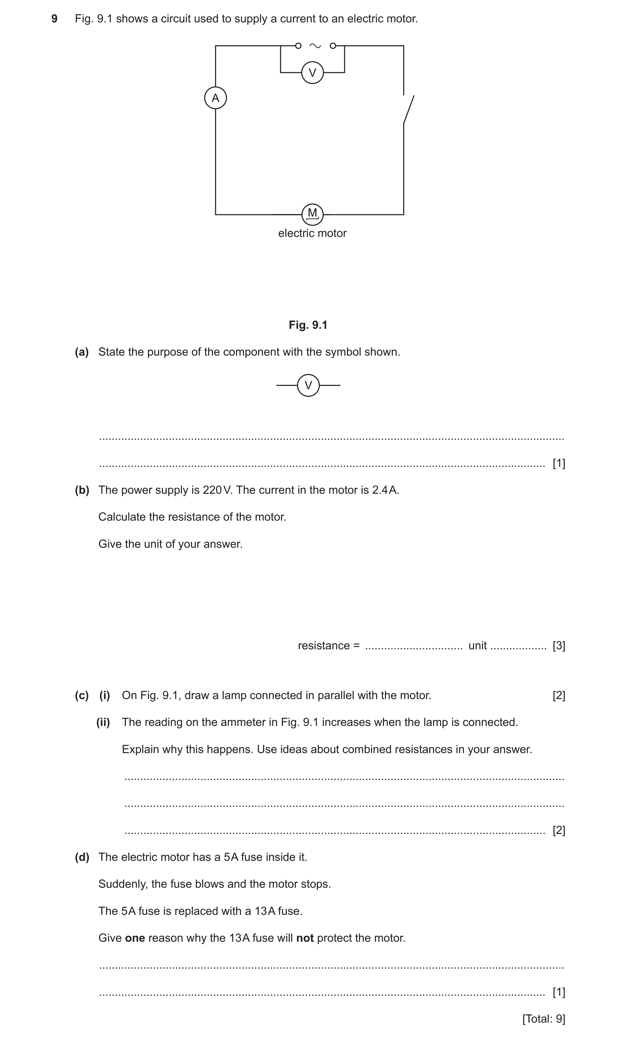
9 Fig. 9.1 shows a circuit used to supply a current to an electric motor. V A M electric motor Fig. 9.1 (a) State the purpose of the component with the symbol shown. V … … [1] (b) The power supply is 220 V. The current in the motor is 2.4 A. Calculate the resistance of the motor. Give the unit of your answer. resistance = … unit … [3] (c) (i) On Fig. 9.1, draw a lamp connected in parallel with the motor. [2] (ii) The reading on the ammeter in Fig. 9.1 increases when the lamp is connected. Explain why this happens. Use ideas about combined resistances in your answer. … … … [2] (d) The electric motor has a 5 A fuse inside it. Suddenly, the fuse blows and the motor stops. The 5 A fuse is replaced with a 13 A fuse. Give one reason why the 13 A fuse will not protect the motor. … … [1] [Total: 9]
9 marks
Mark scheme: 9(a) measures potential difference / p.d ; 1 Question Answer Marks 9(b) resistance = voltage ÷ current (in any form) / R = V ÷ I / 220 ÷ 2.4 ; 92 ; Ω / ohms ; 3 9(c)(i) 2 9(c)(ii) (combined) resistance decreases ; therefore (for the same voltage) the current increases ; 2 9(d) idea that a 13 A fuse allows too much current to flow before, blowing / damaging, components / motor / circuit ; 1 lamp symbol ; connected in parallel (above or below motor) ;
This question in 0653/32 Feb/March 2022
Q17 · Complete the following sentences using the terms shown 0653/31 May/June 2022
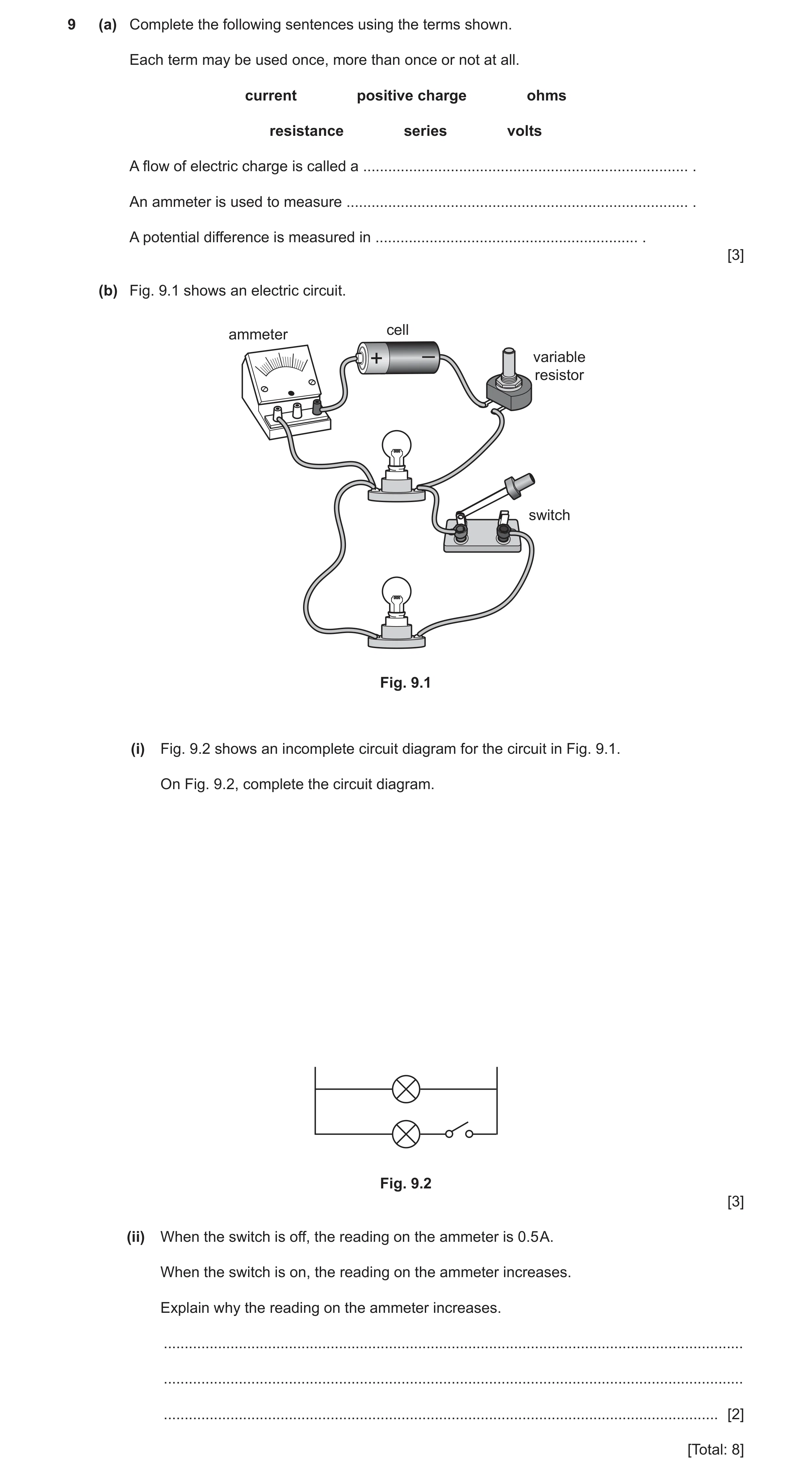
9 (a) Complete the following sentences using the terms shown. Each term may be used once, more than once or not at all. current positive charge ohms resistance series volts A flow of electric charge is called a … . An ammeter is used to measure … . A potential difference is measured in … . [3] (b) Fig. 9.1 shows an electric circuit. cell ammeter variable + – resistor switch Fig. 9.1 (i) Fig. 9.2 shows an incomplete circuit diagram for the circuit in Fig. 9.1. On Fig. 9.2, complete the circuit diagram. Fig. 9.2 [3] (ii) When the switch is off, the reading on the ammeter is 0.5 A. When the switch is on, the reading on the ammeter increases. Explain why the reading on the ammeter increases. … … … [2] [Total: 8]
8 marks
Mark scheme: 9(a) current ; current ; volts ; 3 9(b)(i) variable resistor symbol correct; all other symbols correct ; correct circuit ; 3 Question Answer Marks 9(b)(ii) resistors / lamps in parallel mean total resistance less than either component ; total resistance decreased, so current increases / current from source larger than current in each branch ; 2
This question in 0653/31 May/June 2022
Question 18 0653/32 Feb/March 2023
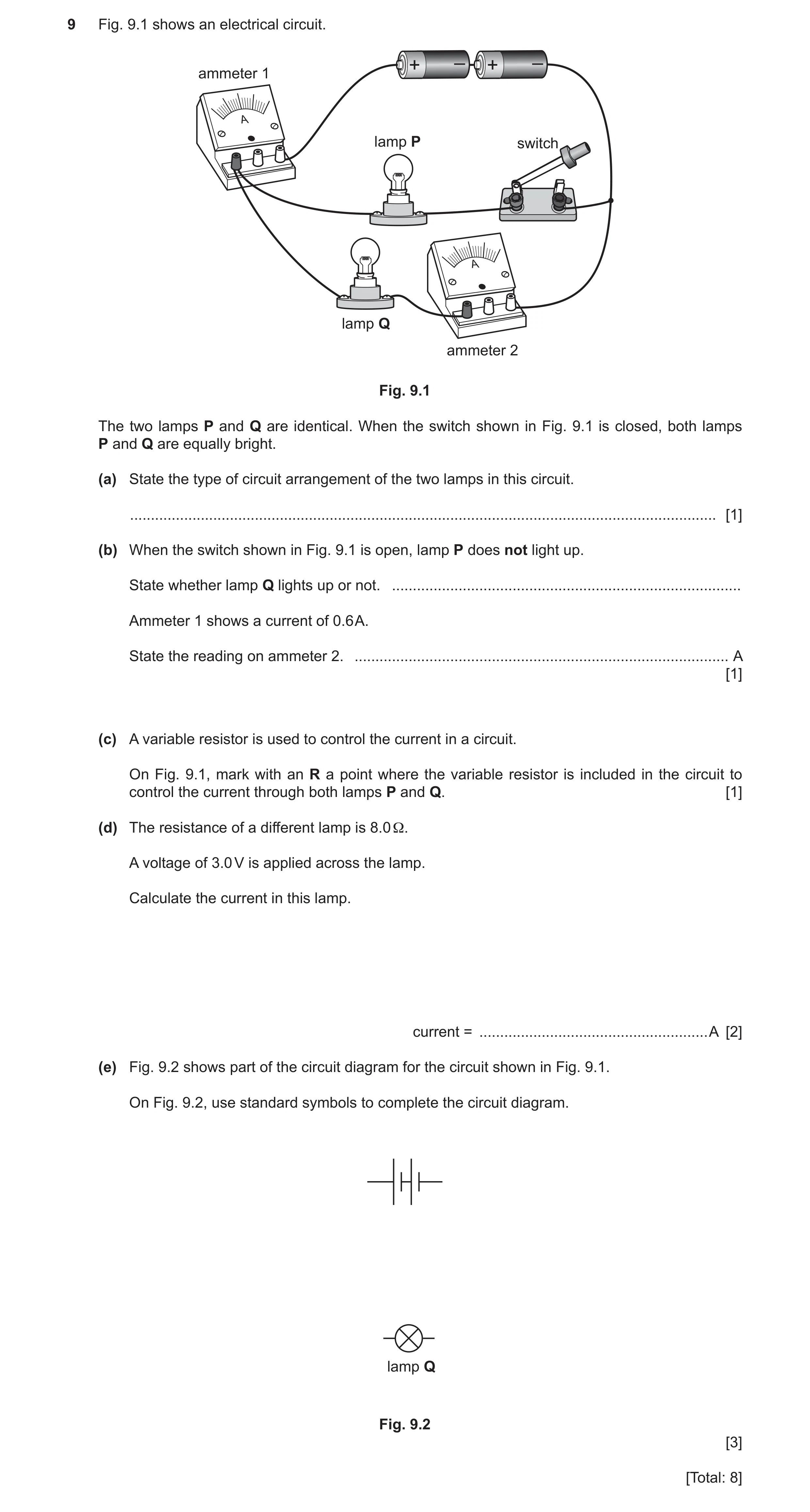
9 Fig. 9.1 shows an electrical circuit. + – + – ammeter 1 A lamp P switch A lamp Q ammeter 2 Fig. 9.1 The two lamps P and Q are identical. When the switch shown in Fig. 9.1 is closed, both lamps P and Q are equally bright. (a) State the type of circuit arrangement of the two lamps in this circuit. … [1] (b) When the switch shown in Fig. 9.1 is open, lamp P does not light up. State whether lamp Q lights up or not. … Ammeter 1 shows a current of 0.6 A. State the reading on ammeter 2. … A [1] (c) A variable resistor is used to control the current in a circuit. On Fig. 9.1, mark with an R a point where the variable resistor is included in the circuit to control the current through both lamps P and Q. [1] (d) The resistance of a different lamp is 8.0 Ω. A voltage of 3.0 V is applied across the lamp. Calculate the current in this lamp. current = … A [2] (e) Fig. 9.2 shows part of the circuit diagram for the circuit shown in Fig. 9.1. On Fig. 9.2, use standard symbols to complete the circuit diagram. lamp Q Fig. 9.2 [3] [Total: 8]
8 marks
Mark scheme: 9(a) parallel ; 1 9(b) yes and 0.6 (A) ; 1 9(c) R marked alongside wiring from battery, either side of battery ; 1 9(d) resistance = voltage current in any form ; 2 3 8 = 0.37(5) / 0.38 (A) ; 9(e) correct symbols for ammeter and switch and a complete circuit ; 3 lamps in parallel connection ; both ammeters and switch in correct positions ;
This question in 0653/32 Feb/March 2023
Question 19 0653/32 May/June 2023
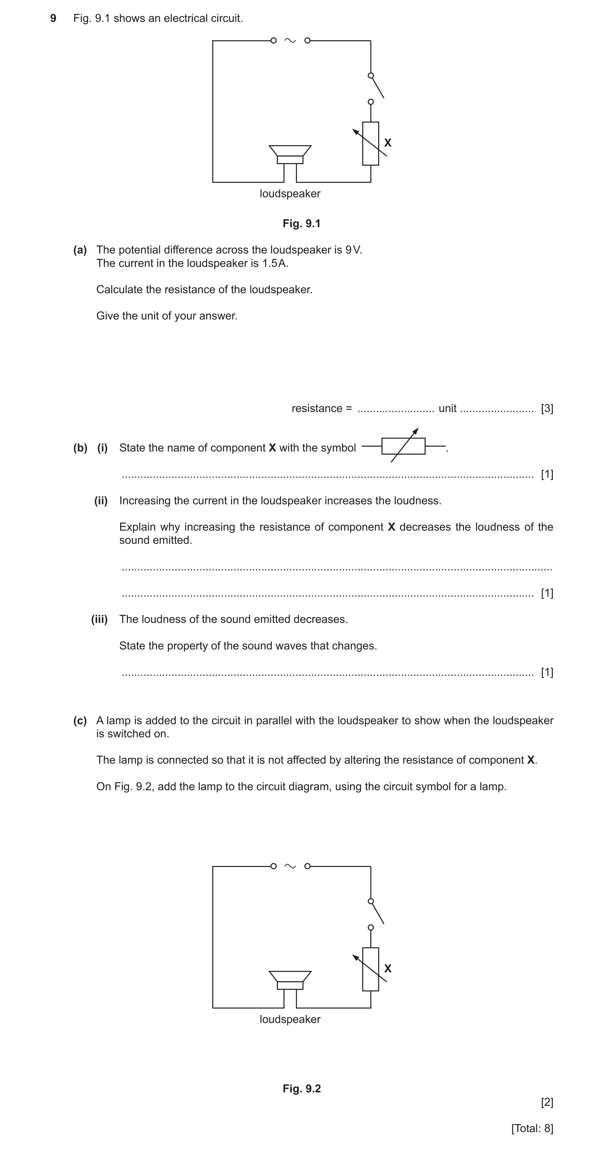
9 Fig. 9.1 shows an electrical circuit. X loudspeaker Fig. 9.1 (a) The potential difference across the loudspeaker is 9 V. The current in the loudspeaker is 1.5 A. Calculate the resistance of the loudspeaker. Give the unit of your answer. resistance = … unit … [3] (b) (i) State the name of component X with the symbol . … [1] (ii) Increasing the current in the loudspeaker increases the loudness. Explain why increasing the resistance of component X decreases the loudness of the sound emitted. … … [1] (iii) The loudness of the sound emitted decreases. State the property of the sound waves that changes. … [1] (c) A lamp is added to the circuit in parallel with the loudspeaker to show when the loudspeaker is switched on. The lamp is connected so that it is not affected by altering the resistance of component X. On Fig. 9.2, add the lamp to the circuit diagram, using the circuit symbol for a lamp. X loudspeaker Fig. 9.2 [2] [Total: 8]
8 marks
Mark scheme: 9(a) (R = ) 6 ; ohms / ; 9(b)(i) variable resistor ; 1 9(b)(ii) current decreases ; 1 Question Answer Marks 9(b)(iii) amplitude ; 1 9(c) lamp symbol ; connected in parallel above or below loudspeaker, but below switch ; 2
This question in 0653/32 May/June 2023
Q20 · A car battery connected to an electric heater used in a caravan 0653/33 May/June 2023
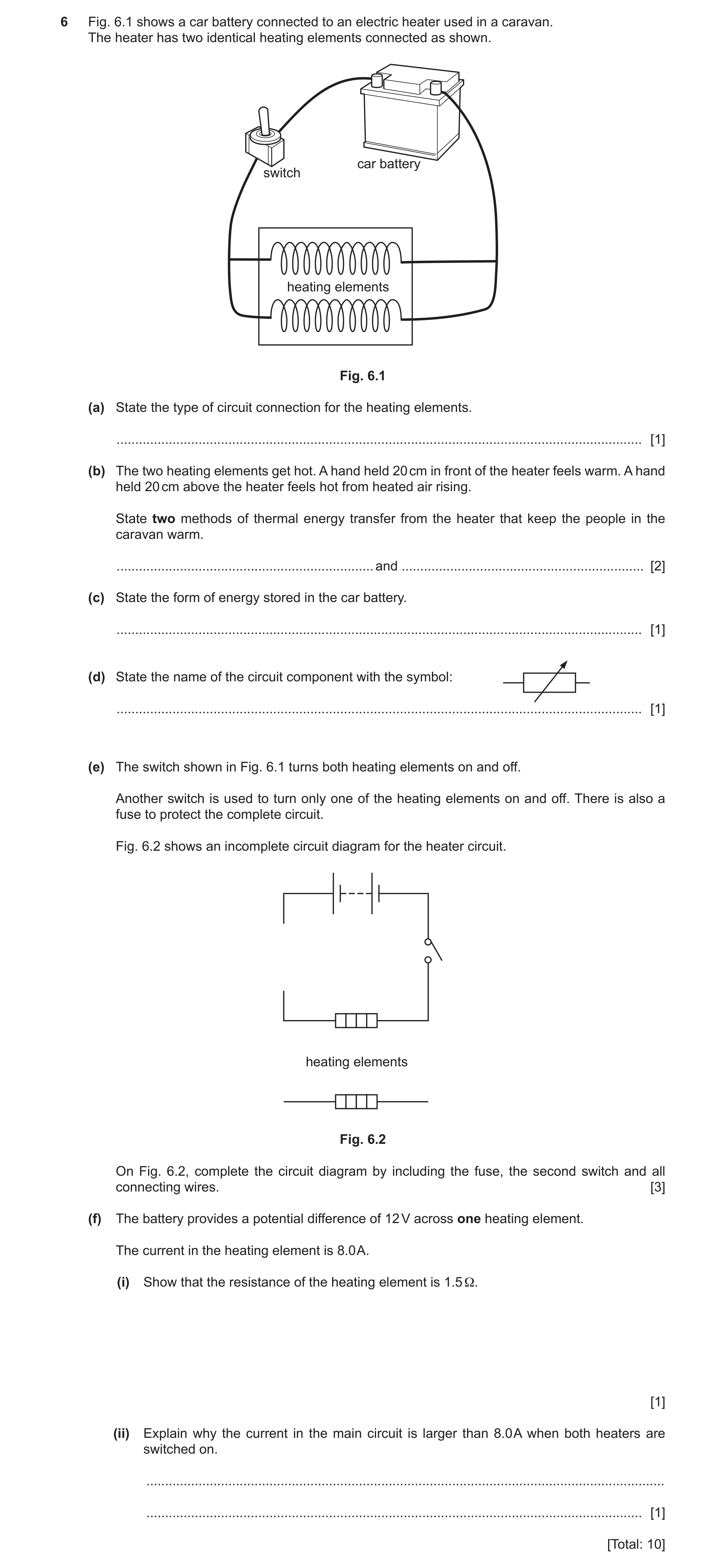
6 Fig. 6.1 shows a car battery connected to an electric heater used in a caravan. The heater has two identical heating elements connected as shown. car battery switch heating elements Fig. 6.1 (a) State the type of circuit connection for the heating elements. … [1] (b) The two heating elements get hot. A hand held 20 cm in front of the heater feels warm. A hand held 20 cm above the heater feels hot from heated air rising. State two methods of thermal energy transfer from the heater that keep the people in the caravan warm. … and … [2] (c) State the form of energy stored in the car battery. … [1] (d) State the name of the circuit component with the symbol: … [1] (e) The switch shown in Fig. 6.1 turns both heating elements on and off. Another switch is used to turn only one of the heating elements on and off. There is also a fuse to protect the complete circuit. Fig. 6.2 shows an incomplete circuit diagram for the heater circuit. heating elements Fig. 6.2 On Fig. 6.2, complete the circuit diagram by including the fuse, the second switch and all connecting wires. [3] (f) The battery provides a potential difference of 12 V across one heating element. The current in the heating element is 8.0 A. (i) Show that the resistance of the heating element is 1.5 Ω. [1] (ii) Explain why the current in the main circuit is larger than 8.0 A when both heaters are switched on. … … [1] [Total: 10]
10 marks
Mark scheme: 6(a) parallel ; 1 6(b) radiation ; convection ; in any order 2 6(c) chemical (potential) ; 1 6(d) variable resistor ; 1 6(e) symbol for fuse ; second switch placed between heating elements ; fuse in main circuit and all connections completed ; 3 6(f)(i) (R =) V I / R = 12 8.0 (= 1.5) ; 1 6(f)(ii) current from source is (always) larger than current in either branch ; 1
This question in 0653/33 May/June 2023
Q21 · A person’s voice emits sound in the form of longitudinal waves 0653/33 May/June 2023
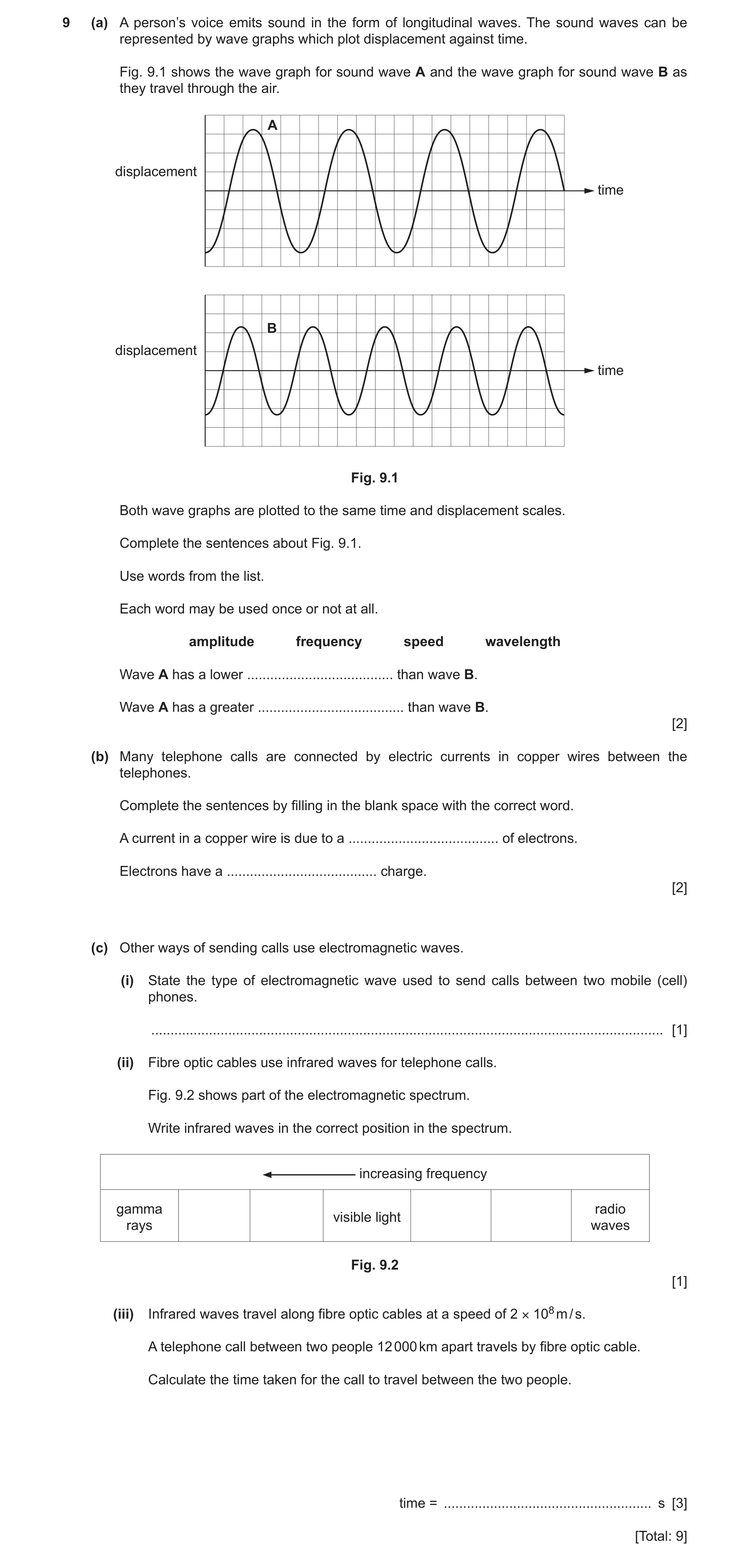
9 (a) A person’s voice emits sound in the form of longitudinal waves. The sound waves can be represented by wave graphs which plot displacement against time. Fig. 9.1 shows the wave graph for sound wave A and the wave graph for sound wave B as they travel through the air. A displacement time B displacement time Fig. 9.1 Both wave graphs are plotted to the same time and displacement scales. Complete the sentences about Fig. 9.1. Use words from the list. Each word may be used once or not at all. amplitude frequency speed wavelength Wave A has a lower … than wave B. Wave A has a greater … than wave B. [2] (b) Many telephone calls are connected by electric currents in copper wires between the telephones. Complete the sentences by filling in the blank space with the correct word. A current in a copper wire is due to a … of electrons. Electrons have a … charge. [2] (c) Other ways of sending calls use electromagnetic waves. (i) State the type of electromagnetic wave used to send calls between two mobile (cell) phones. … [1] (ii) Fibre optic cables use infrared waves for telephone calls. Fig. 9.2 shows part of the electromagnetic spectrum. Write infrared waves in the correct position in the spectrum. increasing frequency gamma radio visible light rays waves Fig. 9.2 [1] (iii) Infrared waves travel along fibre optic cables at a speed of 2 × 10⁸ m / s. A telephone call between two people 12 000 km apart travels by fibre optic cable. Calculate the time taken for the call to travel between the two people. time = … s [3] [Total: 9]
9 marks
Mark scheme: 9(a) frequency ; wavelength / amplitude ; 2 9(b) movement / flow ; negative ; 2 9(c)(i) microwave ; 1 9(c)(ii) gamma rays visible light infrared ; radio waves 1 9(c)(iii) unit conversion seen anywhere OR 12 000 km = 12 106 m ; speed = distance time (in any form) OR 12 106 2 108 ; 6(.0) 10–2 / 0.06(0) (s) ; 3
This question in 0653/33 May/June 2023
Q22 · A student determines the resistance of resistor R 0653/31 Oct/Nov 2023
6 A student determines the resistance of resistor R. Fig. 6.1 shows resistor R connected in series with a battery and an ammeter. A R Fig. 6.1 (a) The reading on the ammeter is 0.24 A. (i) State the name of the quantity measured by the ammeter. … [1] (ii) The student connects a voltmeter to measure the potential difference (p.d.) across resistor R. On Fig. 6.1, draw a voltmeter symbol and show how the student connects the voltmeter to take this measurement. [2] (iii) The potential difference across resistor R is 3.6 V. Calculate the resistance of resistor R. Give the unit of your answer. resistance = … unit … [3] (b) Resistor S has the same resistance as resistor R. (i) The student connects resistor S in series with resistor R. Fig. 6.2 shows the circuit. A R S Fig. 6.2 State the reading on the ammeter. reading = … A [1] (ii) The student connects resistor S in parallel with resistor R. Fig. 6.3 shows the circuit. A R S Fig. 6.3 Describe how the reading on the ammeter compares to the reading in (a). Give a reason for your answer. description … reason … … … [2] [Total: 9]
9 marks
Mark scheme: 6(a)(i) current ; 1 6(a)(ii) correct symbol for voltmeter ; 2 connected in parallel across R ; 6(a)(iii) evidence of, R = V ÷ I / 3.6 ÷ 0.24 ; 3 15 ; ohms / ; 6(b)(i) 0.12 (A) ; 1 6(b)(ii) increases / greater ; 2 the combined resistance of two resistors in parallel is less than that of either resistor by itself ;
This question in 0653/31 Oct/Nov 2023
Q23 · A wind turbine used to generate electricity for the electrical system of a house 0653/32 Oct/Nov 2023
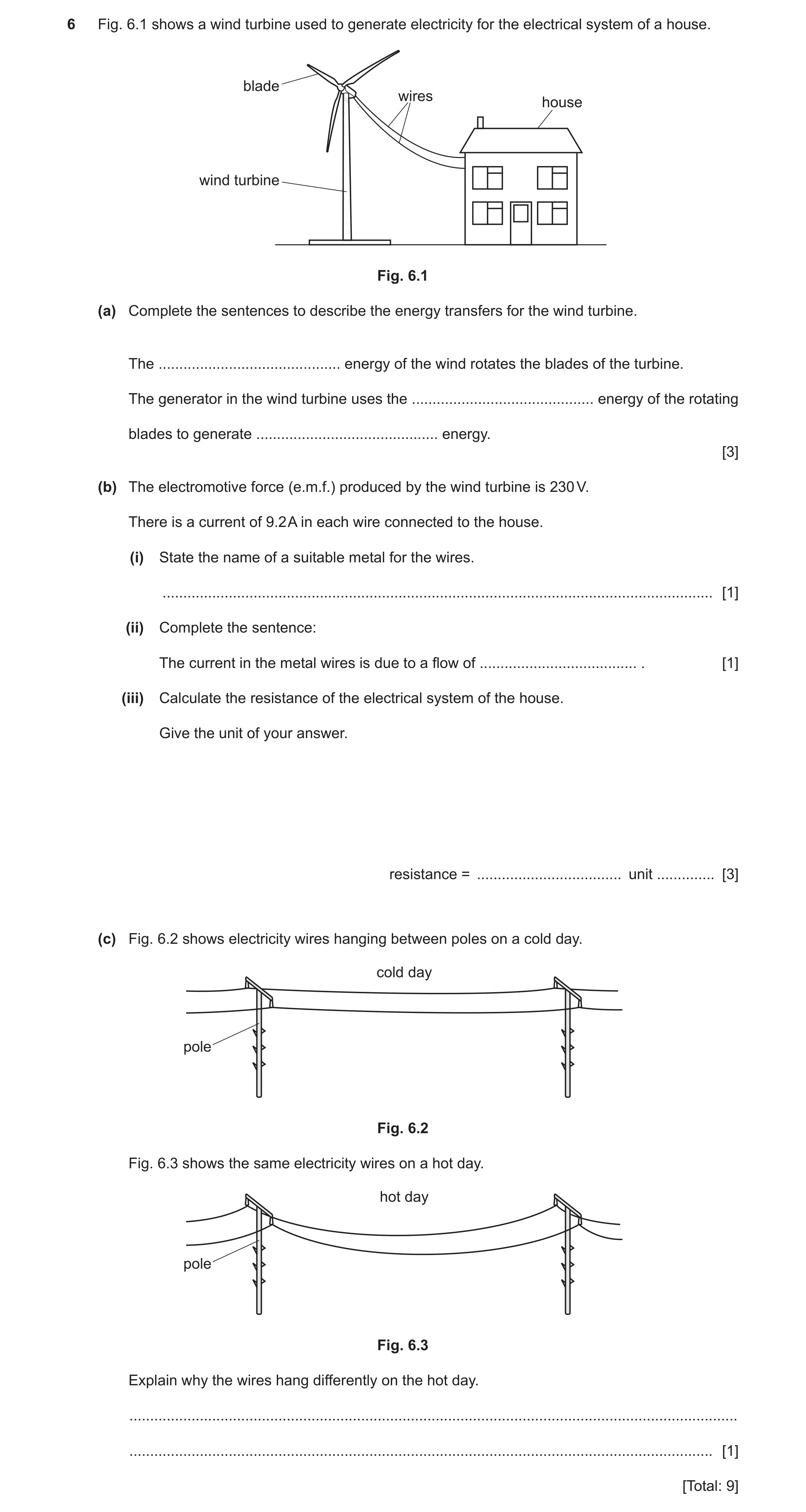
6 Fig. 6.1 shows a wind turbine used to generate electricity for the electrical system of a house. blade wires house wind turbine Fig. 6.1 (a) Complete the sentences to describe the energy transfers for the wind turbine. The … energy of the wind rotates the blades of the turbine. The generator in the wind turbine uses the … energy of the rotating blades to generate … energy. [3] (b) The electromotive force (e.m.f.) produced by the wind turbine is 230 V. There is a current of 9.2 A in each wire connected to the house. (i) State the name of a suitable metal for the wires. … [1] (ii) Complete the sentence: The current in the metal wires is due to a flow of … . [1] (iii) Calculate the resistance of the electrical system of the house. Give the unit of your answer. resistance = … unit … [3] (c) Fig. 6.2 shows electricity wires hanging between poles on a cold day. cold day pole Fig. 6.2 Fig. 6.3 shows the same electricity wires on a hot day. hot day pole Fig. 6.3 Explain why the wires hang differently on the hot day. … … [1] [Total: 9]
9 marks
Mark scheme: 6(a) kinetic ; 3 kinetic ; electrical ; 6(b)(i) copper ; 1 6(b)(ii) electrons ; 1 6(b)(iii) evidence of, R = V ÷ I / 230 ÷ 9.2 ; 3 25 ; / ohm(s) ; 6(c) idea of (thermal) expansion (with increase in temperature on hot day) ; 1
This question in 0653/32 Oct/Nov 2023
Q24 · A wind turbine used to generate electricity for the electrical system of a house 0653/33 Oct/Nov 2023
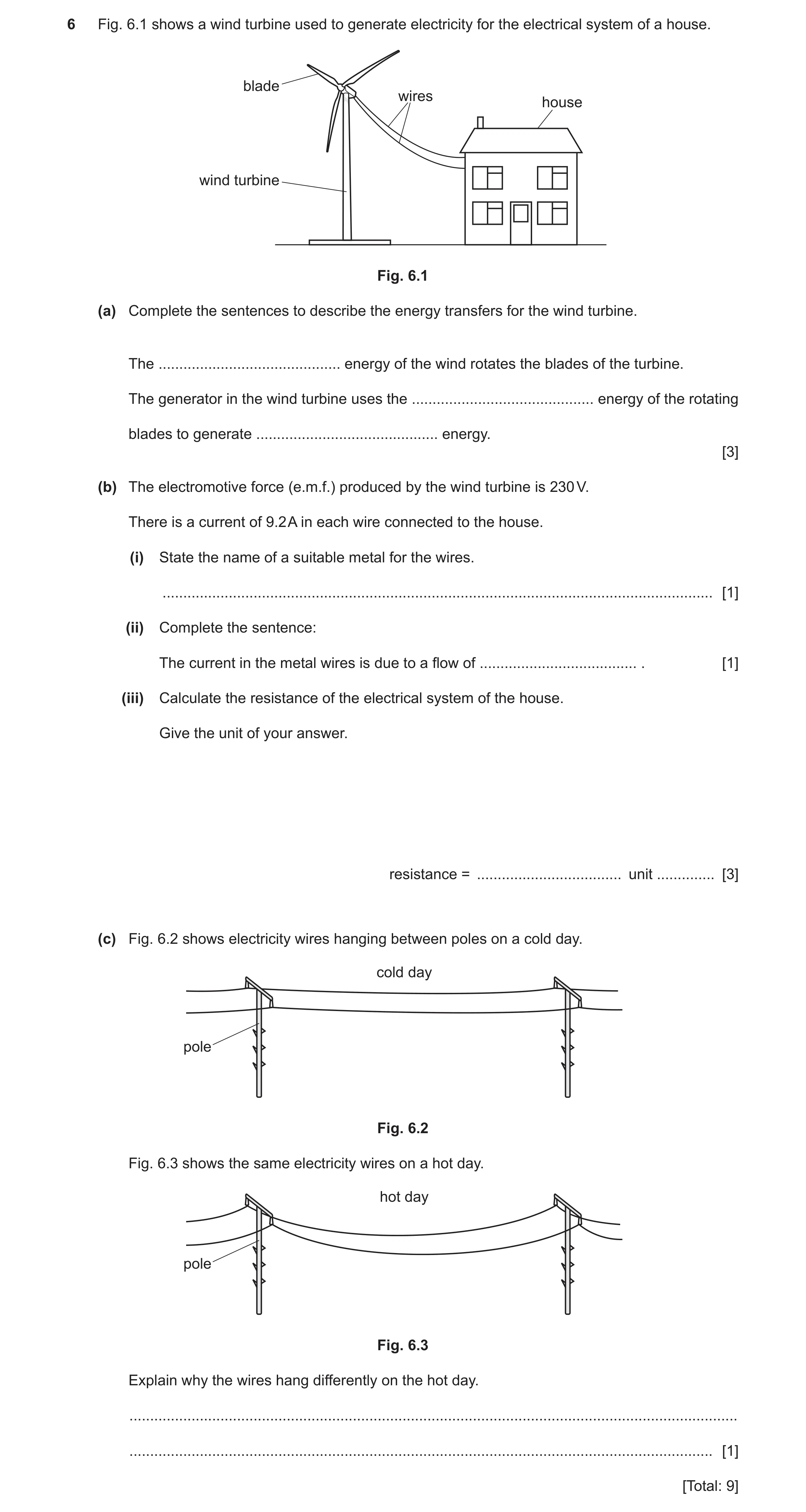
6 Fig. 6.1 shows a wind turbine used to generate electricity for the electrical system of a house. blade wires house wind turbine Fig. 6.1 (a) Complete the sentences to describe the energy transfers for the wind turbine. The … energy of the wind rotates the blades of the turbine. The generator in the wind turbine uses the … energy of the rotating blades to generate … energy. [3] (b) The electromotive force (e.m.f.) produced by the wind turbine is 230 V. There is a current of 9.2 A in each wire connected to the house. (i) State the name of a suitable metal for the wires. … [1] (ii) Complete the sentence: The current in the metal wires is due to a flow of … . [1] (iii) Calculate the resistance of the electrical system of the house. Give the unit of your answer. resistance = … unit … [3] (c) Fig. 6.2 shows electricity wires hanging between poles on a cold day. cold day pole Fig. 6.2 Fig. 6.3 shows the same electricity wires on a hot day. hot day pole Fig. 6.3 Explain why the wires hang differently on the hot day. … … [1] [Total: 9]
9 marks
Mark scheme: 6(a) kinetic ; 3 kinetic ; electrical ; 6(b)(i) copper ; 1 6(b)(ii) electrons ; 1 6(b)(iii) evidence of, R = V ÷ I / 230 ÷ 9.2 ; 3 25 ; / ohm(s) ; 6(c) idea of (thermal) expansion (with increase in temperature on hot day) ; 1
This question in 0653/33 Oct/Nov 2023
Q25 · A student investigates the current in different resistors by connecting them in a circuit… 0653/32 May/June 2024
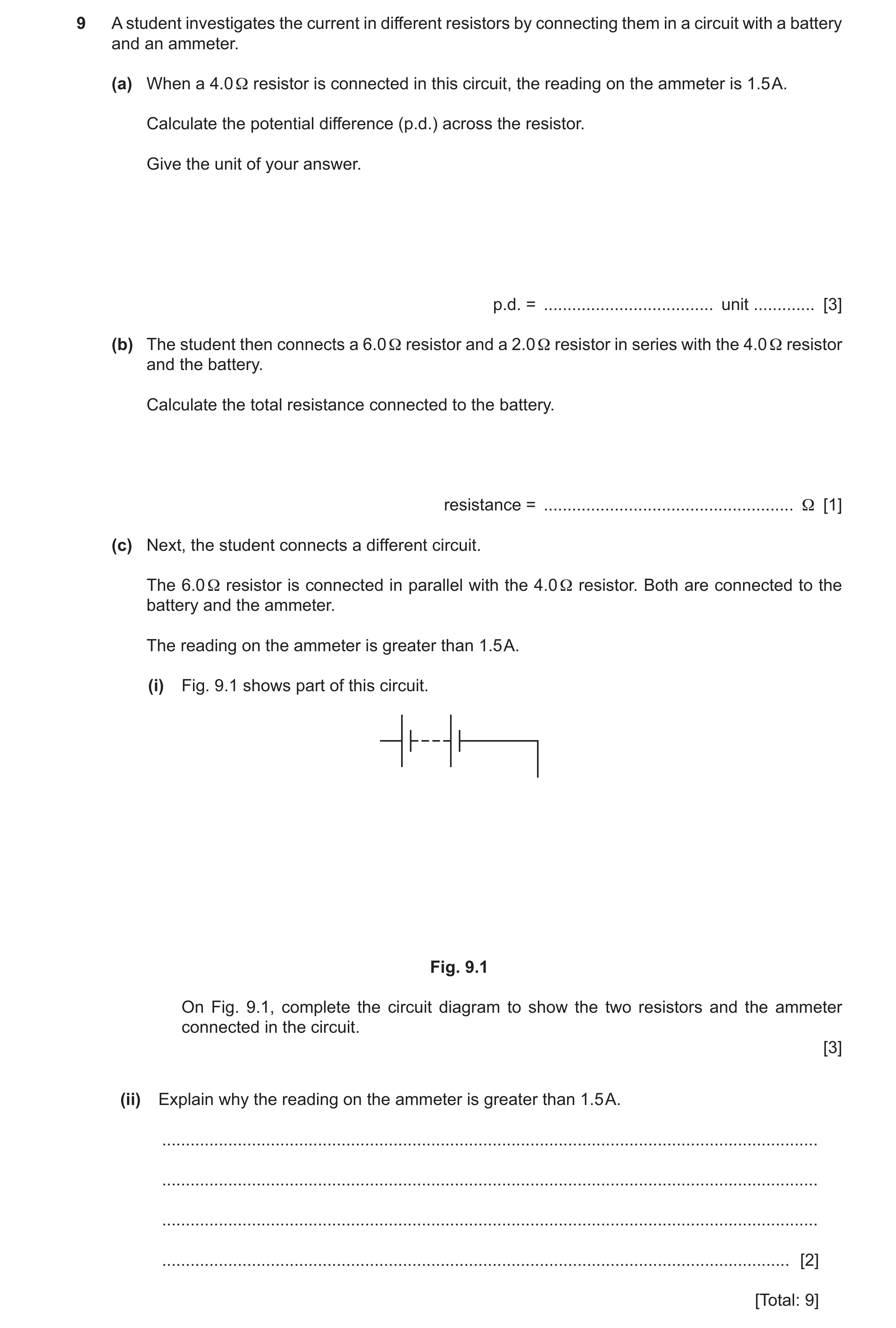
9 A student investigates the current in different resistors by connecting them in a circuit with a battery and an ammeter. (a) When a 4.0 Ω resistor is connected in this circuit, the reading on the ammeter is 1.5 A. Calculate the potential difference (p.d.) across the resistor. Give the unit of your answer. p.d. = … unit … [3] (b) The student then connects a 6.0 Ω resistor and a 2.0 Ω resistor in series with the 4.0 Ω resistor and the battery. Calculate the total resistance connected to the battery. resistance = … Ω [1] (c) Next, the student connects a different circuit. The 6.0 Ω resistor is connected in parallel with the 4.0 Ω resistor. Both are connected to the battery and the ammeter. The reading on the ammeter is greater than 1.5 A. (i) Fig. 9.1 shows part of this circuit. Fig. 9.1 On Fig. 9.1, complete the circuit diagram to show the two resistors and the ammeter connected in the circuit. [3] (ii) Explain why the reading on the ammeter is greater than 1.5 A. … … … … [2] [Total: 9]
9 marks
Mark scheme: 9(a) 6.0 ; V / volts ; 9(b) 6.0 + 2.0 + 4.0 = 12 () ; 1 9(c)(i) correct symbols for both resistors and ammeter ; connection of parallel resistors to battery ; ammeter in main series circuit ; 3 9(c)(ii) combined resistance of two resistors in parallel less than either alone ; resistance less, so current / ammeter reading more (than 1.5 A / than in 4.0 resistor alone) ; 2
This question in 0653/32 May/June 2024
Q26 · An electrical circuit used to investigate the resistance of a lamp 0653/31 Oct/Nov 2024
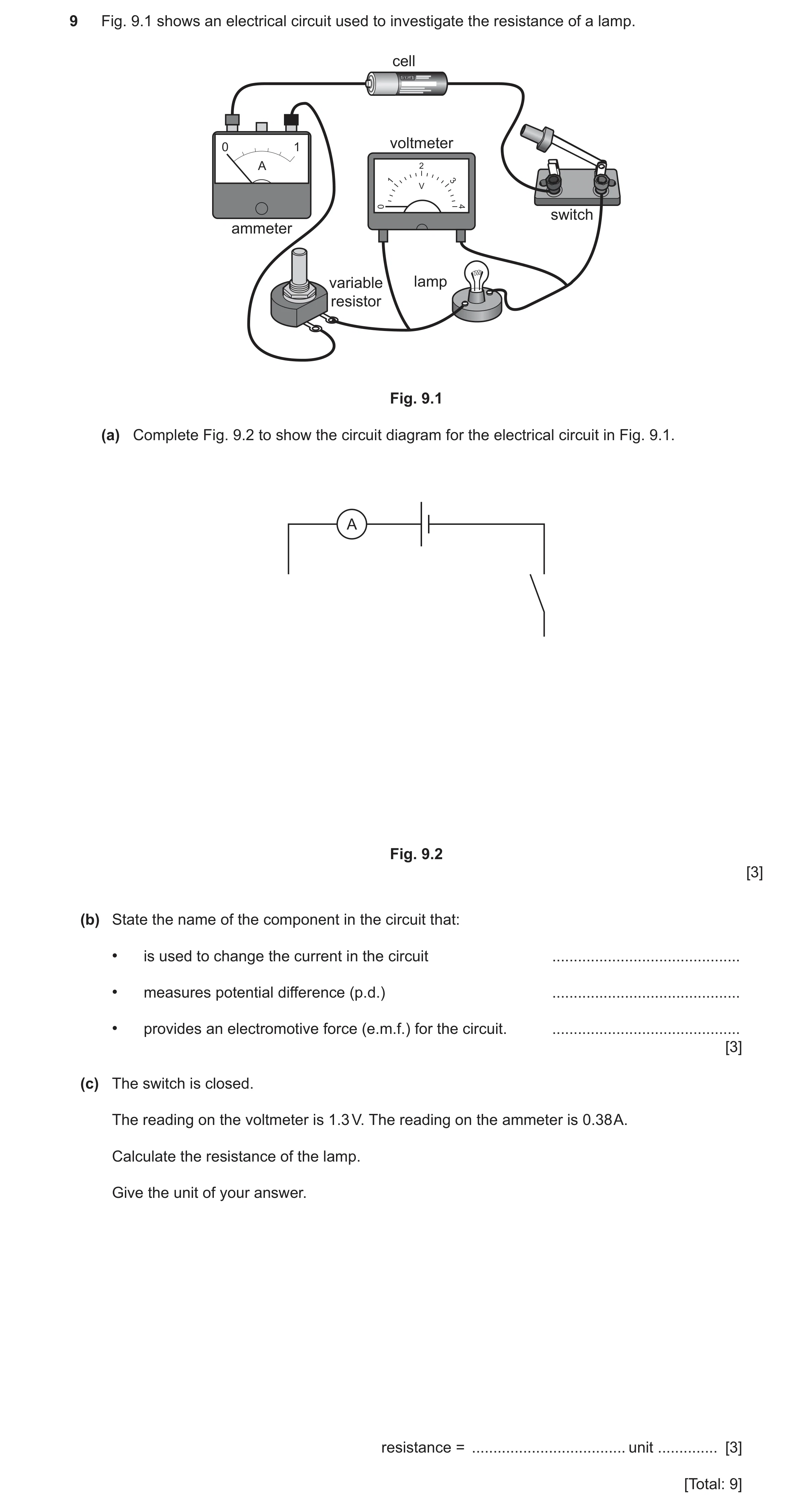
9 Fig. 9.1 shows an electrical circuit used to investigate the resistance of a lamp. cell 0 1 voltmeter A switch ammeter variable lamp resistor Fig. 9.1 (a) Complete Fig. 9.2 to show the circuit diagram for the electrical circuit in Fig. 9.1. A Fig. 9.2 [3] (b) State the name of the component in the circuit that: • is used to change the current in the circuit … • measures potential difference (p.d.) … • provides an electromotive force (e.m.f.) for the circuit. … [3] (c) The switch is closed. The reading on the voltmeter is 1.3 V. The reading on the ammeter is 0.38 A. Calculate the resistance of the lamp. Give the unit of your answer. resistance = … unit … [3] [Total: 9]
9 marks
Mark scheme: 9(a) 3 two correct symbols ; three correct symbols ; correct connections ; 9(b) variable resistor ; 3 voltmeter ; cell ; 9(c) evidence of R = V ÷ I / 1.3 ÷ 0.38 ; 3 3.4 ; / ohm(s) ;
This question in 0653/31 Oct/Nov 2024
Q27 · An electric heater that heats a room 0653/32 May/June 2025
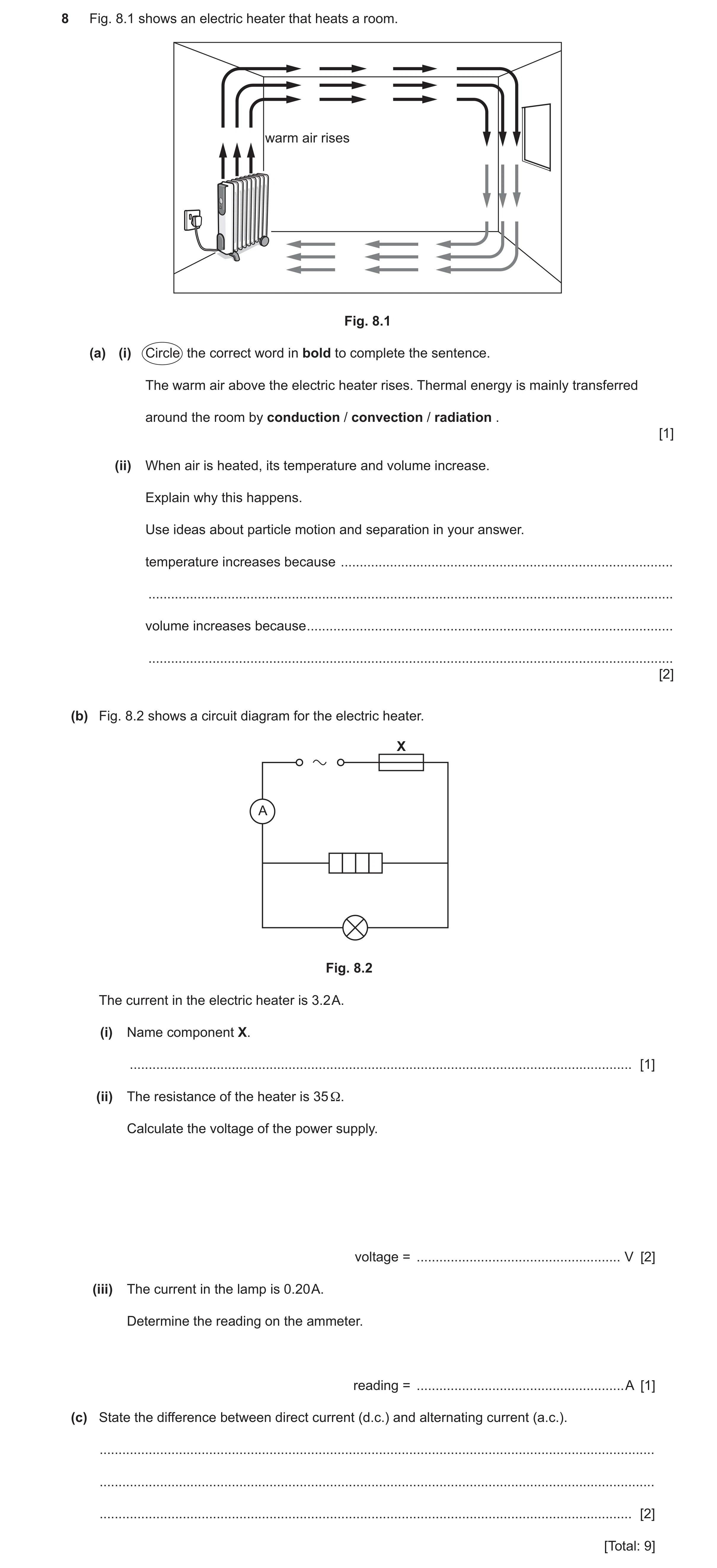
8 Fig. 8.1 shows an electric heater that heats a room. warm air rises Fig. 8.1 (a) (i) Circle the correct word in bold to complete the sentence. The warm air above the electric heater rises. Thermal energy is mainly transferred around the room by conduction / convection / radiation . [1] (ii) When air is heated, its temperature and volume increase. Explain why this happens. Use ideas about particle motion and separation in your answer. temperature increases because … … volume increases because … … [2] (b) Fig. 8.2 shows a circuit diagram for the electric heater. X A Fig. 8.2 The current in the electric heater is 3.2 A. (i) Name component X. … [1] (ii) The resistance of the heater is 35 Ω. Calculate the voltage of the power supply. voltage = … V [2] (iii) The current in the lamp is 0.20 A. Determine the reading on the ammeter. reading = … A [1] (c) State the difference between direct current (d.c.) and alternating current (a.c.). … … … [2] [Total: 9]
9 marks
Mark scheme: 8(a)(i) convection ; 1 8(a)(ii) particles move faster ; 2 particles (move) further apart ; 8(b)(i) fuse ; 1 8(b)(ii) V = R I / voltage = current resistance / 3.2 35 ; 2 112 (V) ; 8(b)(iii) (3.2 + 0.20 =) 3.4 (A) ; 1 8(c) d.c. current goes in one direction only all the time ; 2 a.c. current reverses direction repeatedly ;
This question in 0653/32 May/June 2025
 1 / 40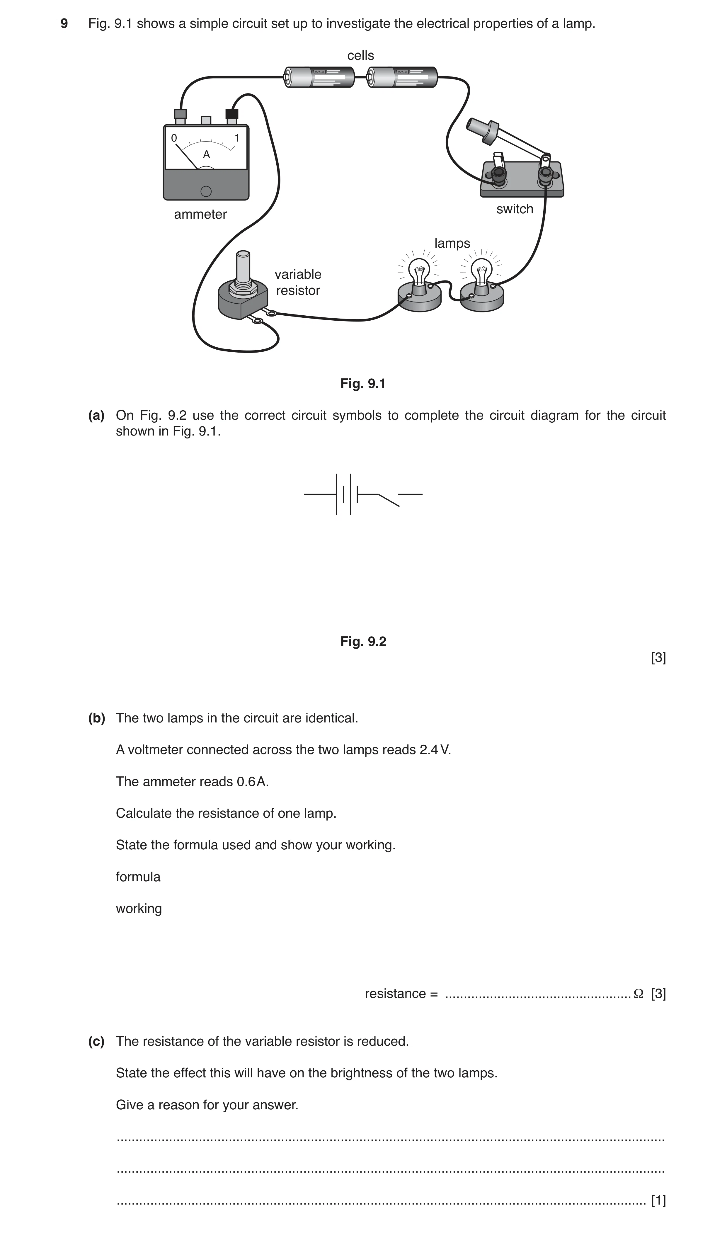
 21 / 40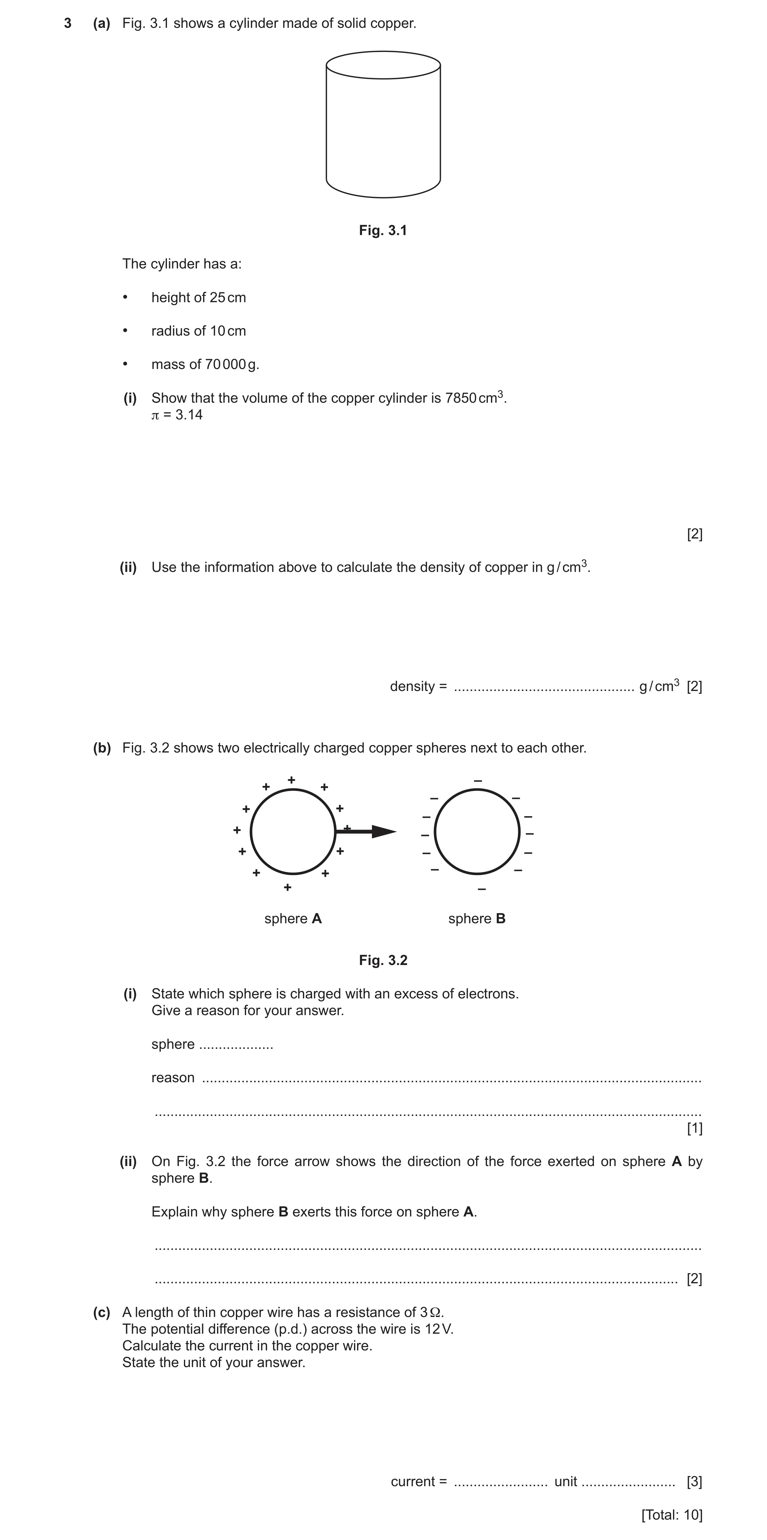

 9
9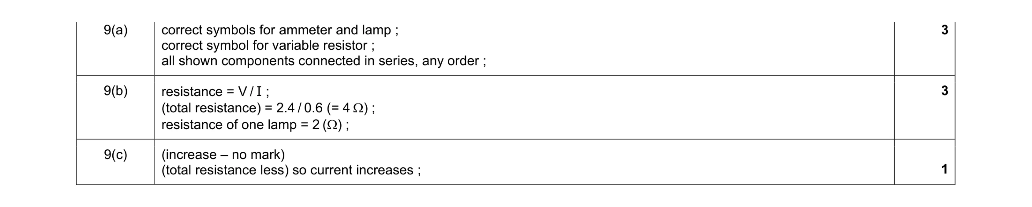 7
7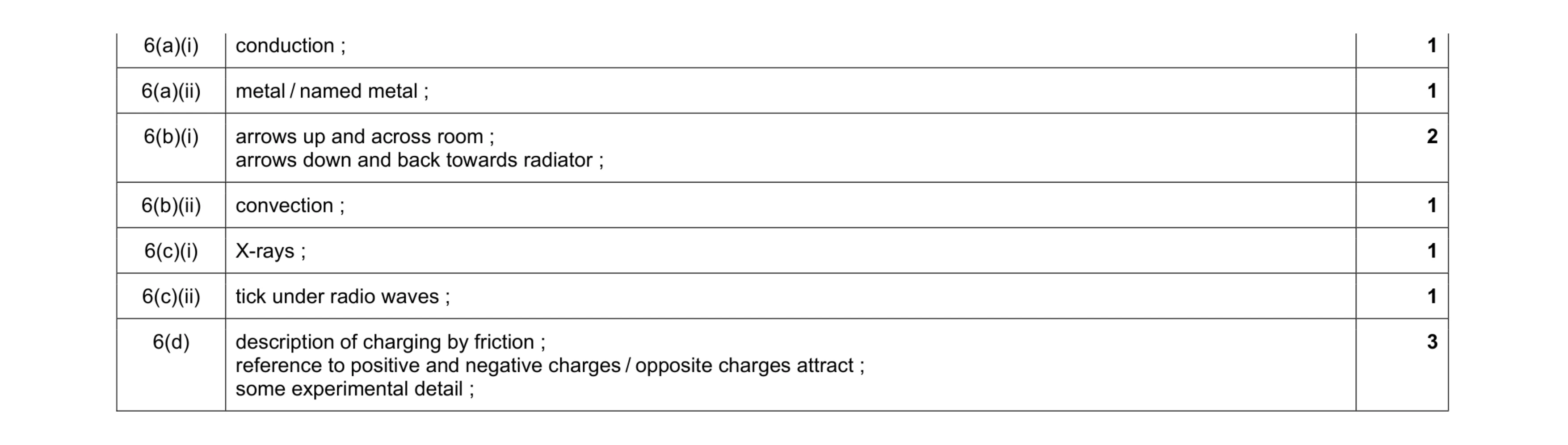 10
10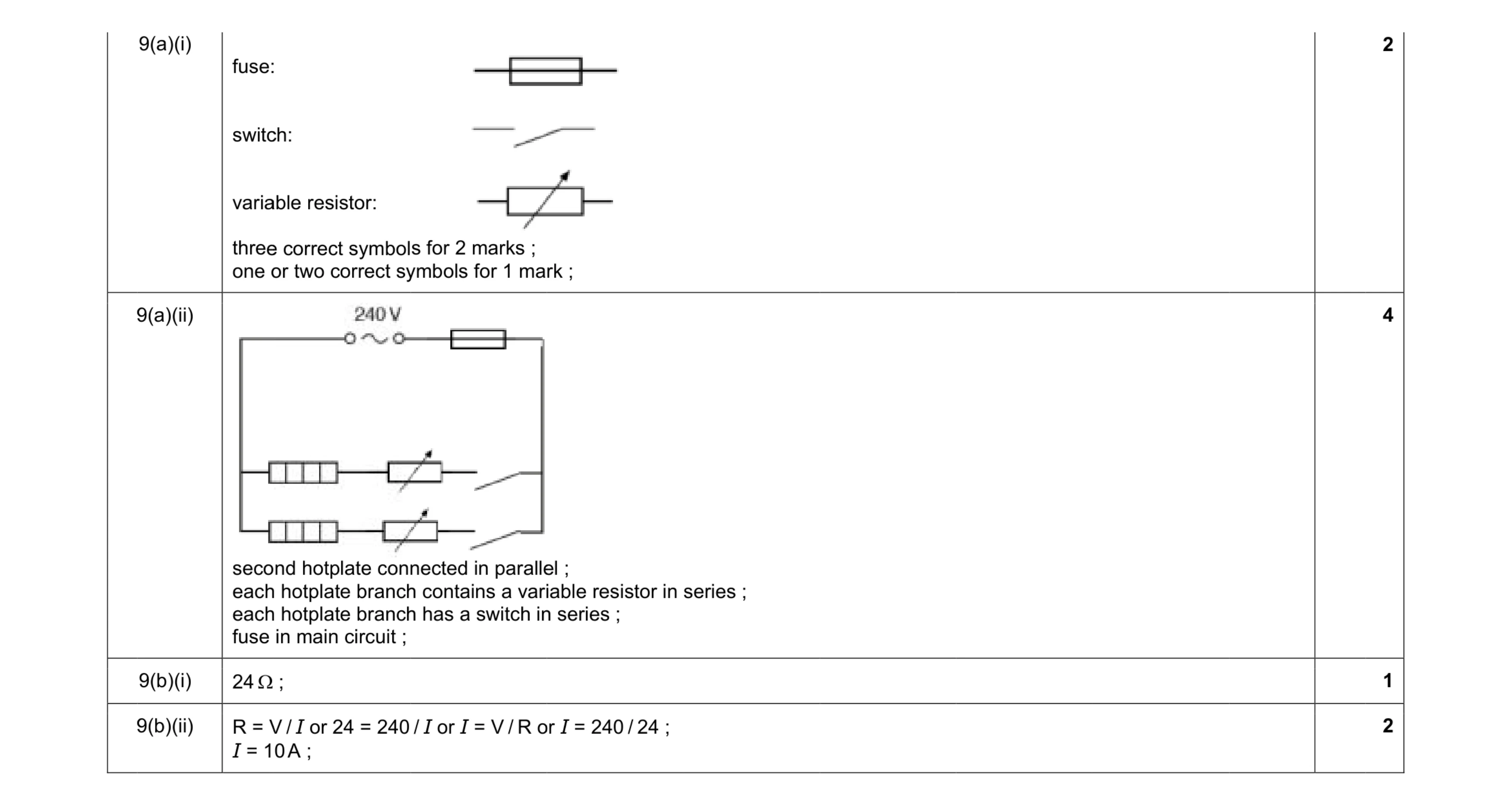 9
9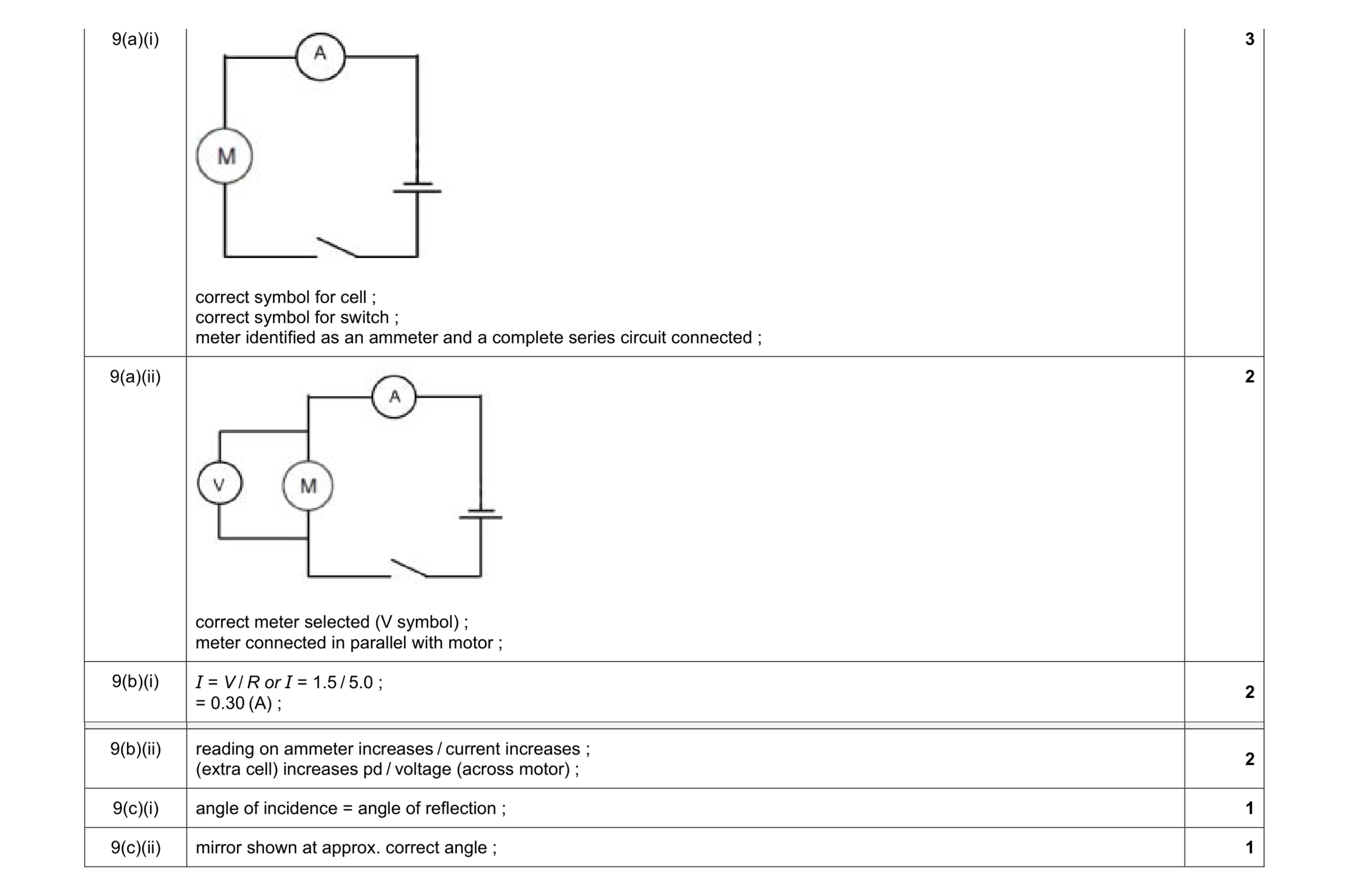 11
11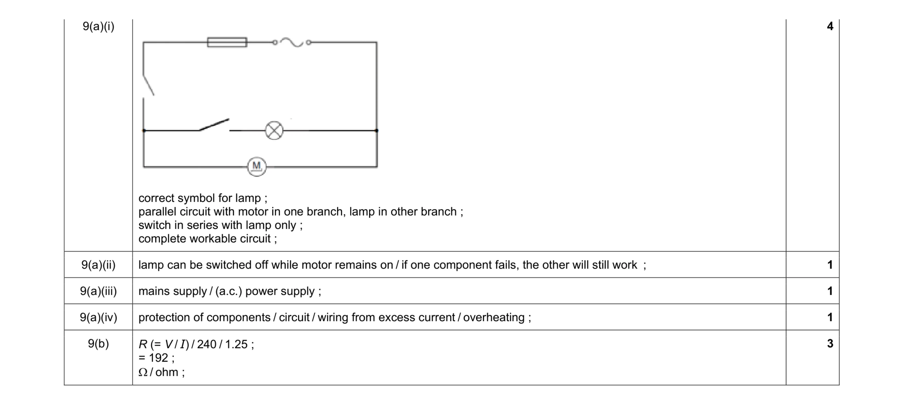 10
10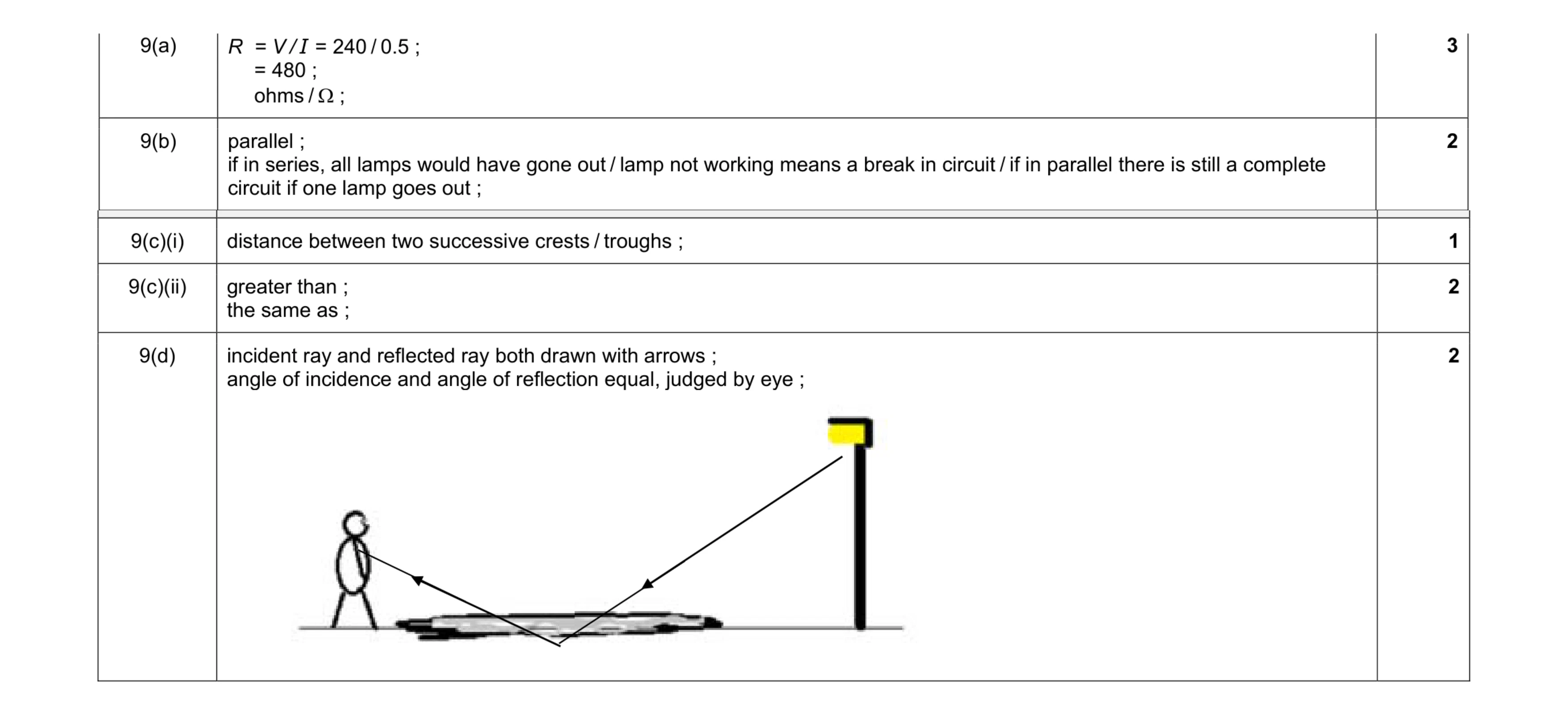 10
10 8
8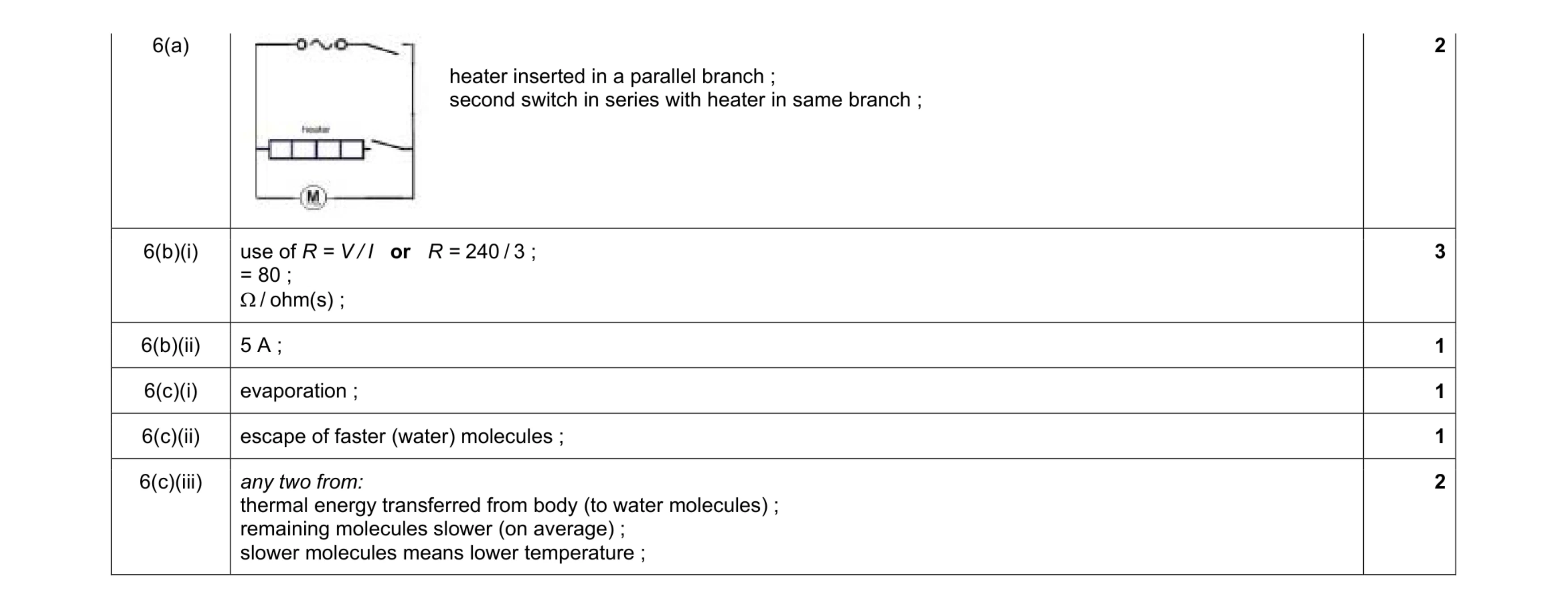 10
10 8
8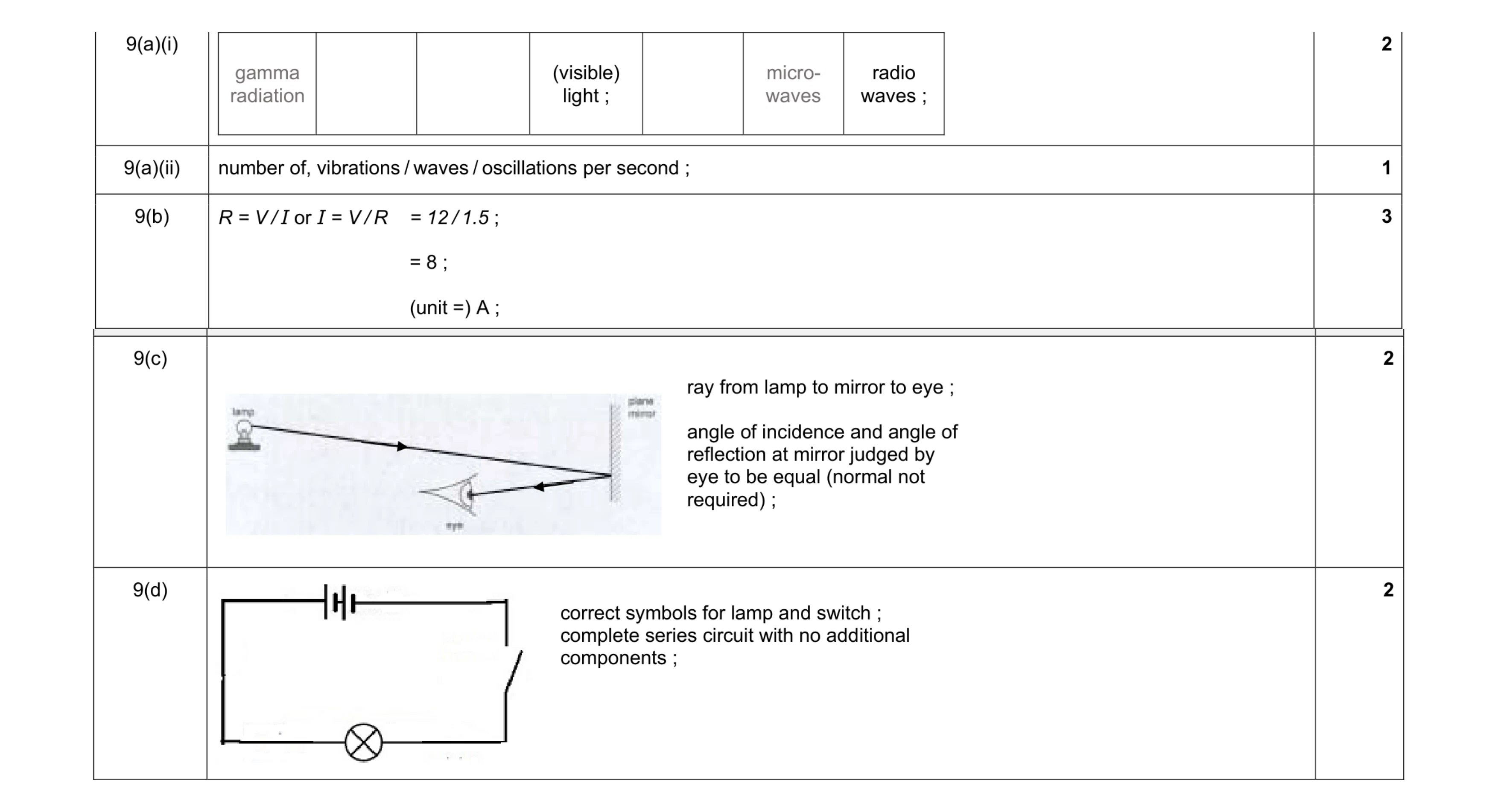 10
10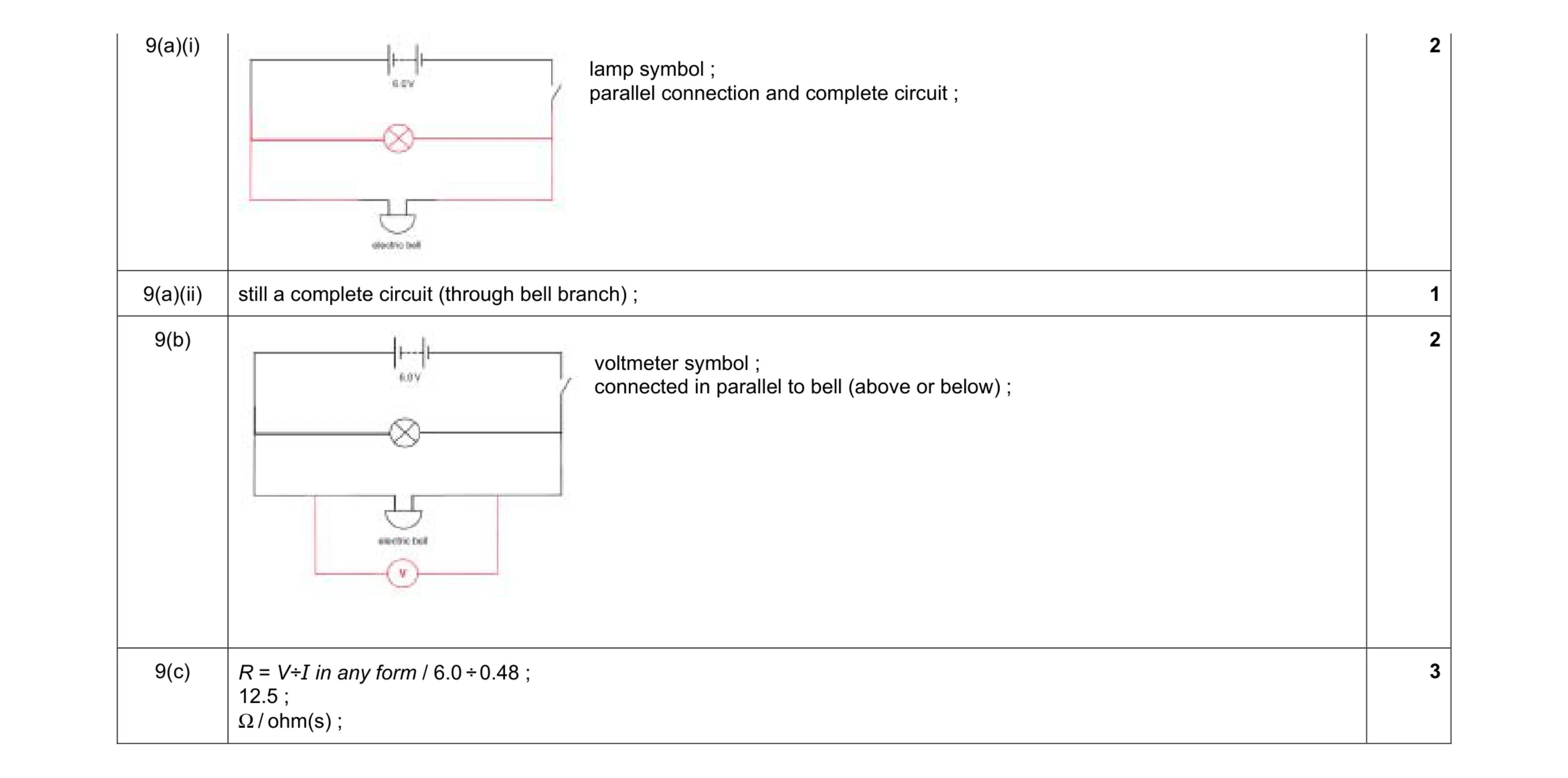 8
8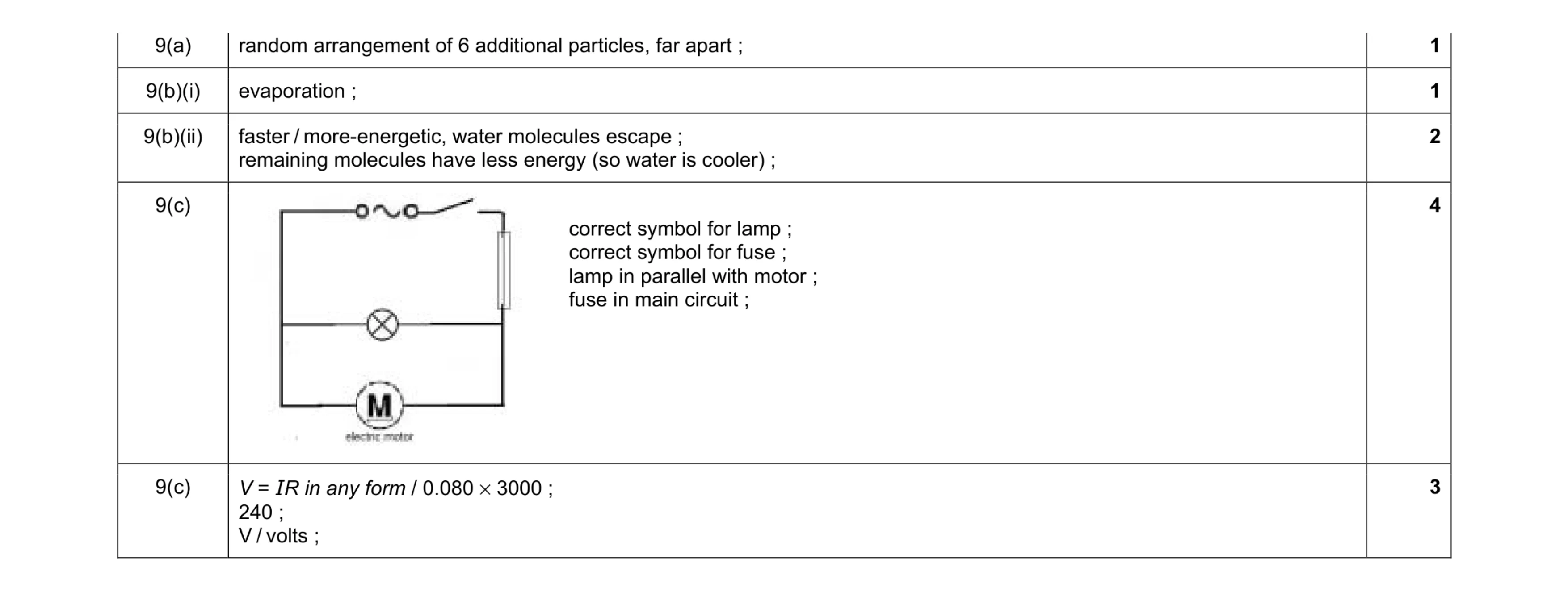 11
11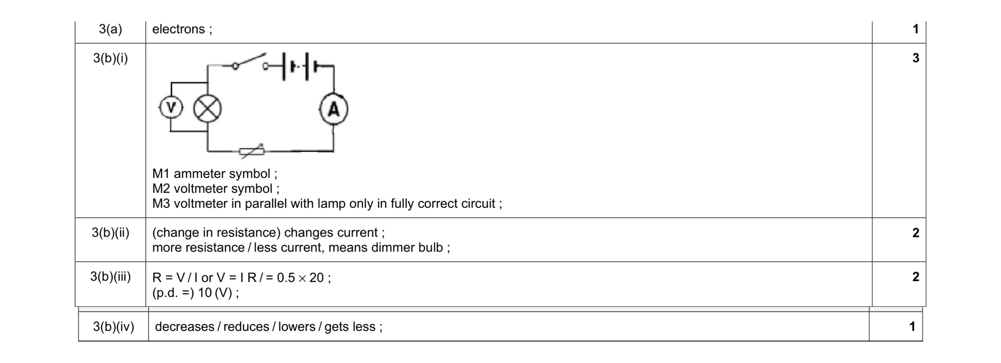 9
9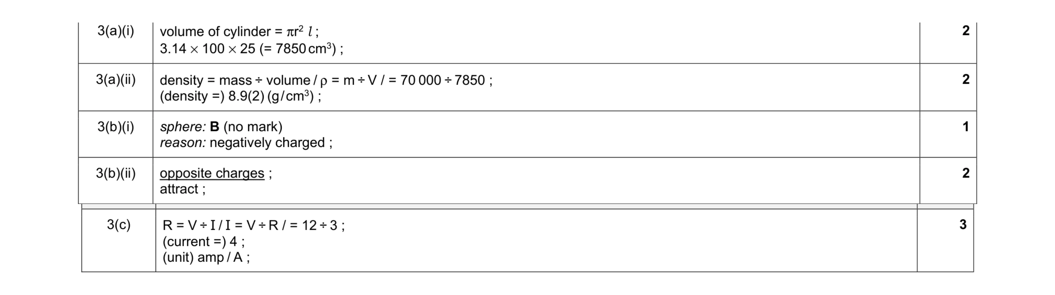 10
10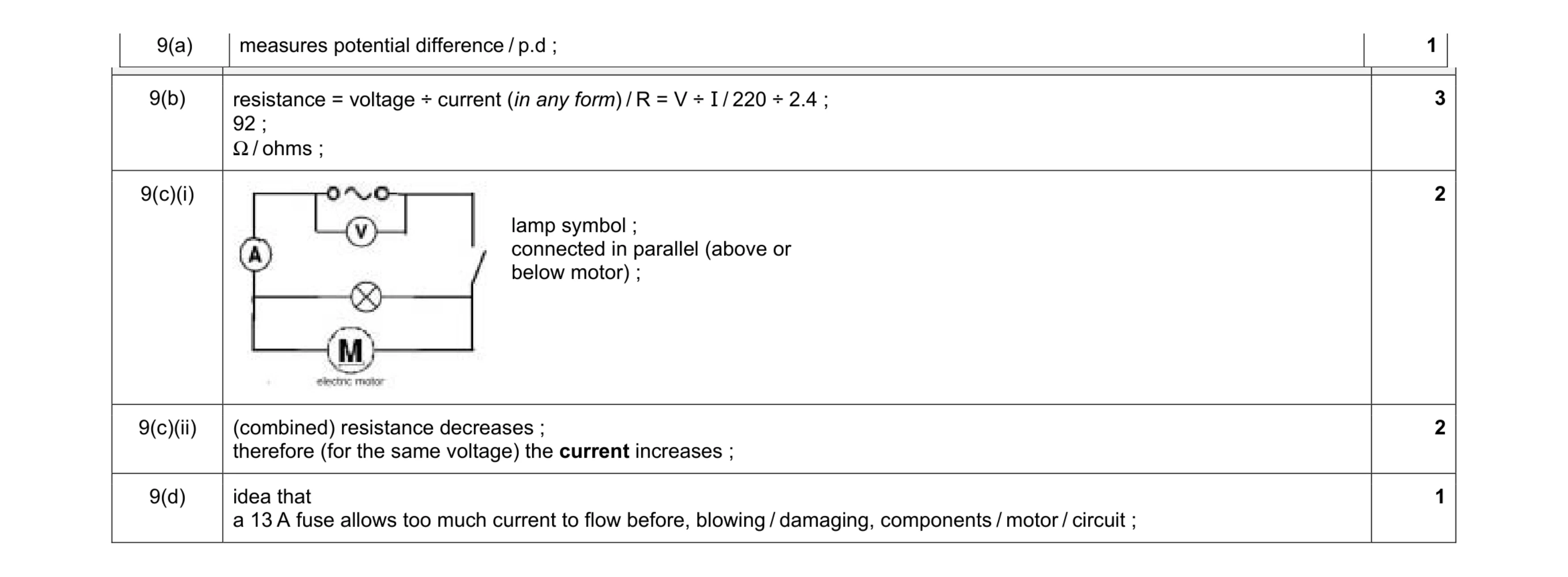 9
9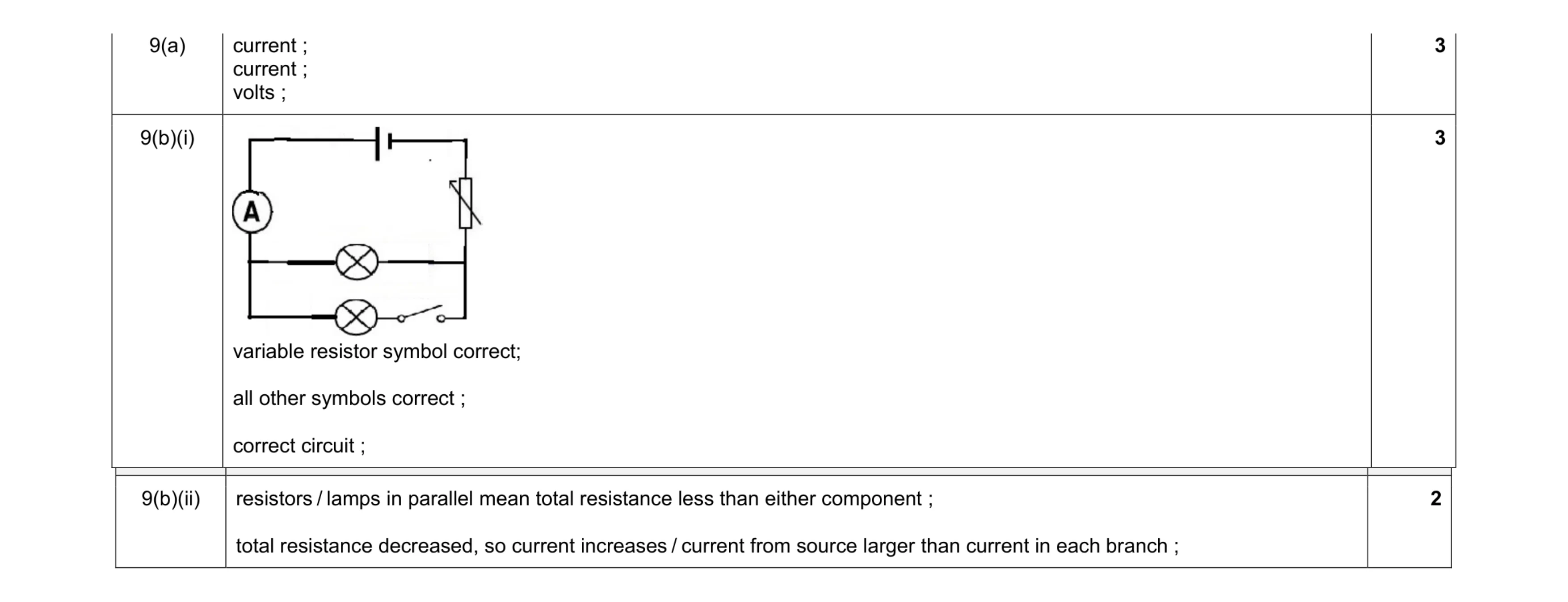 8
8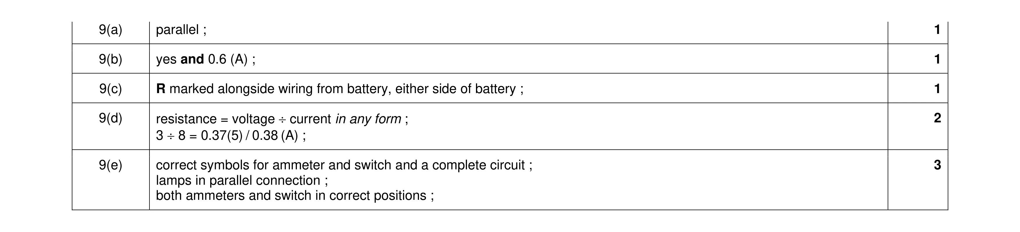 8
8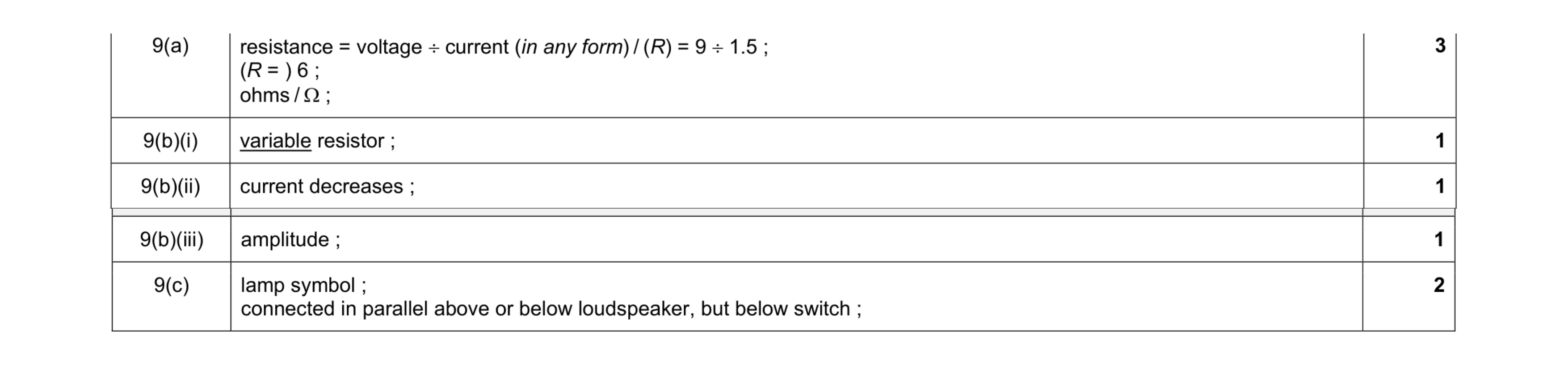 8
8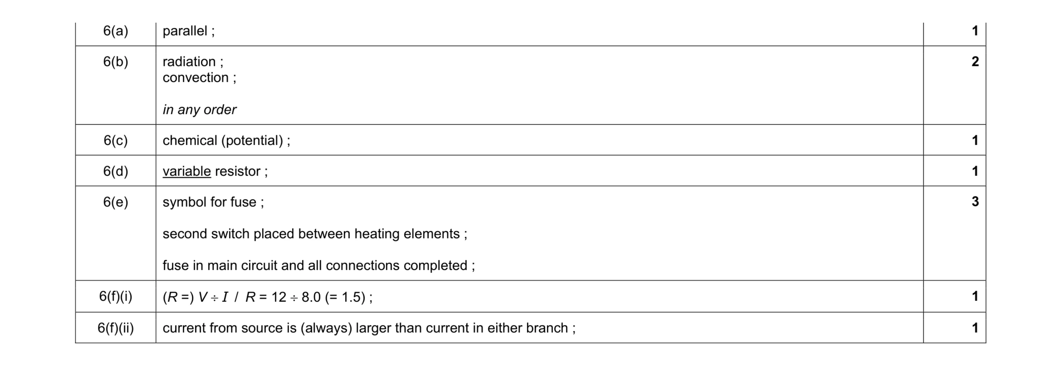 10
10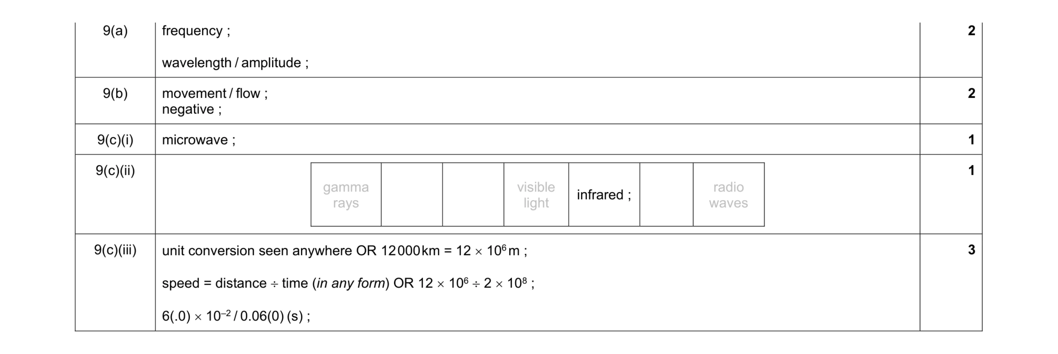 9
9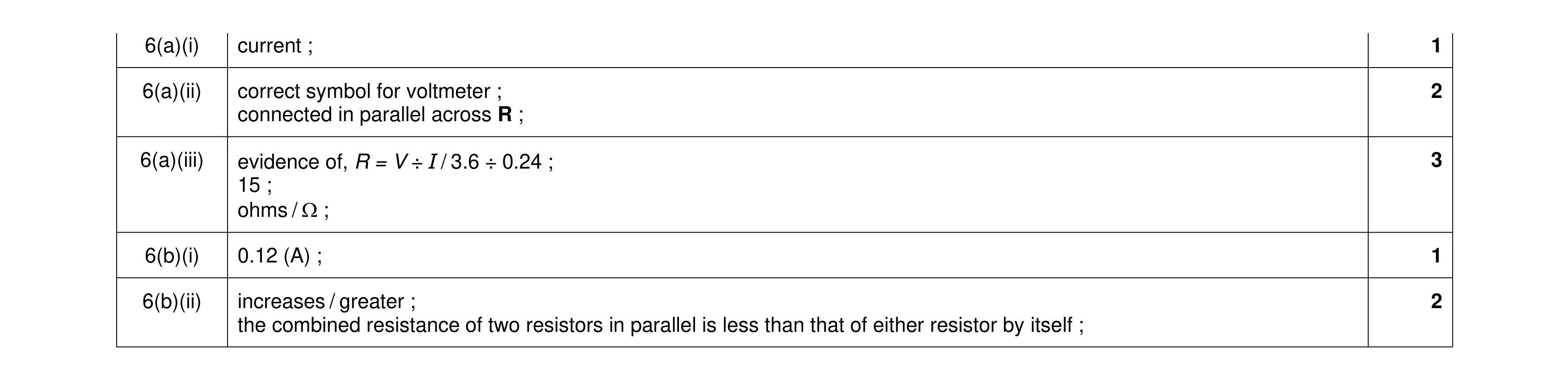 9
9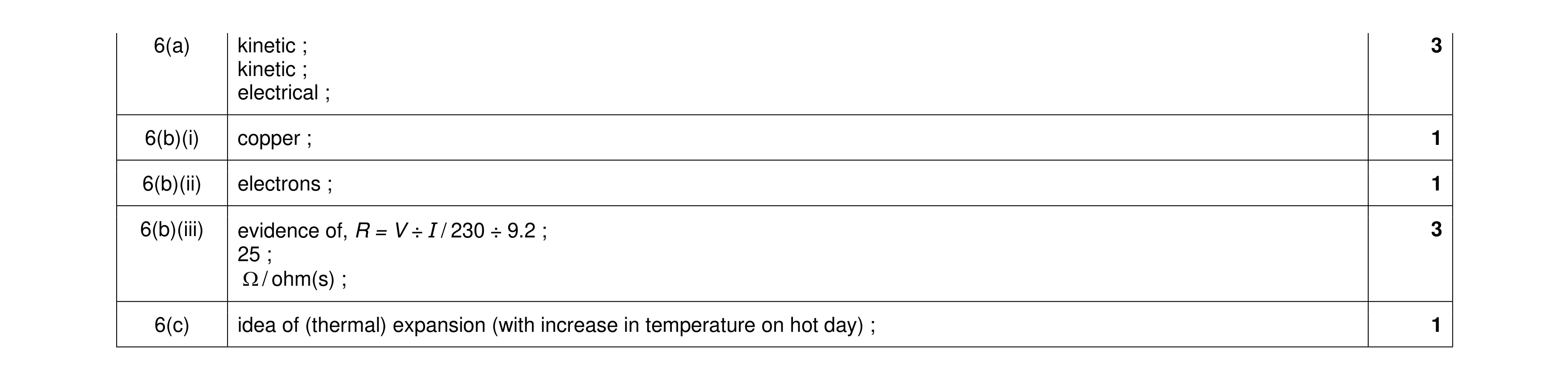 9
9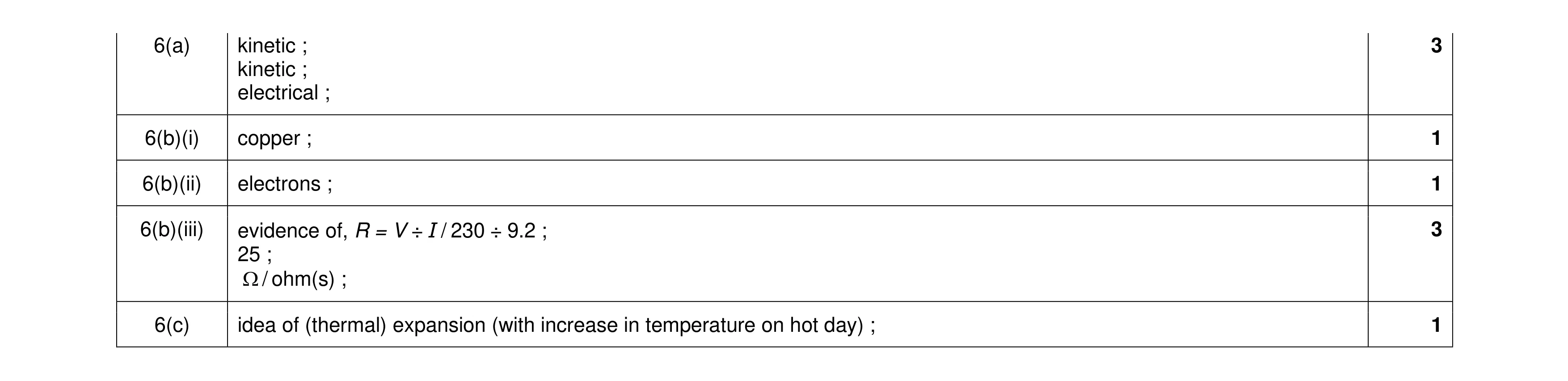 9
9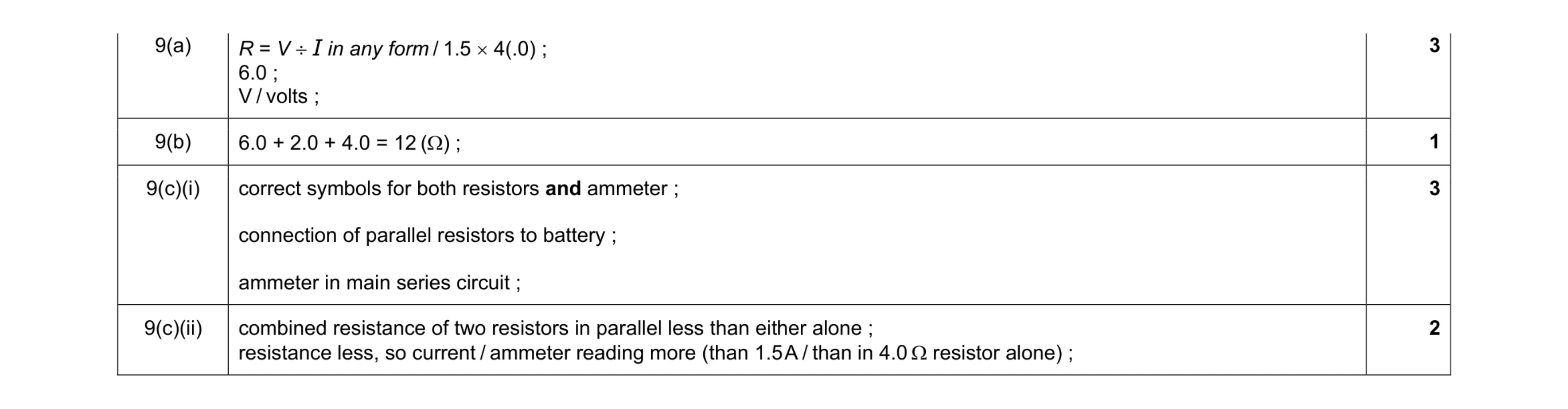 9
9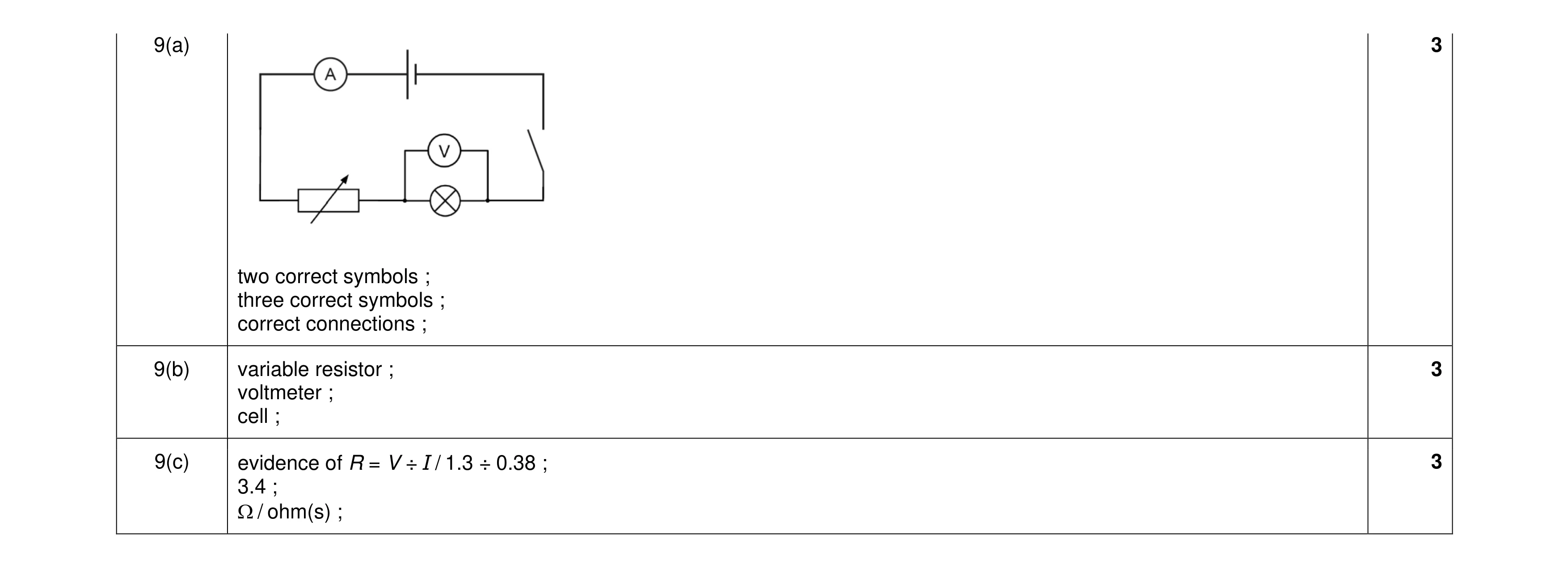 9
9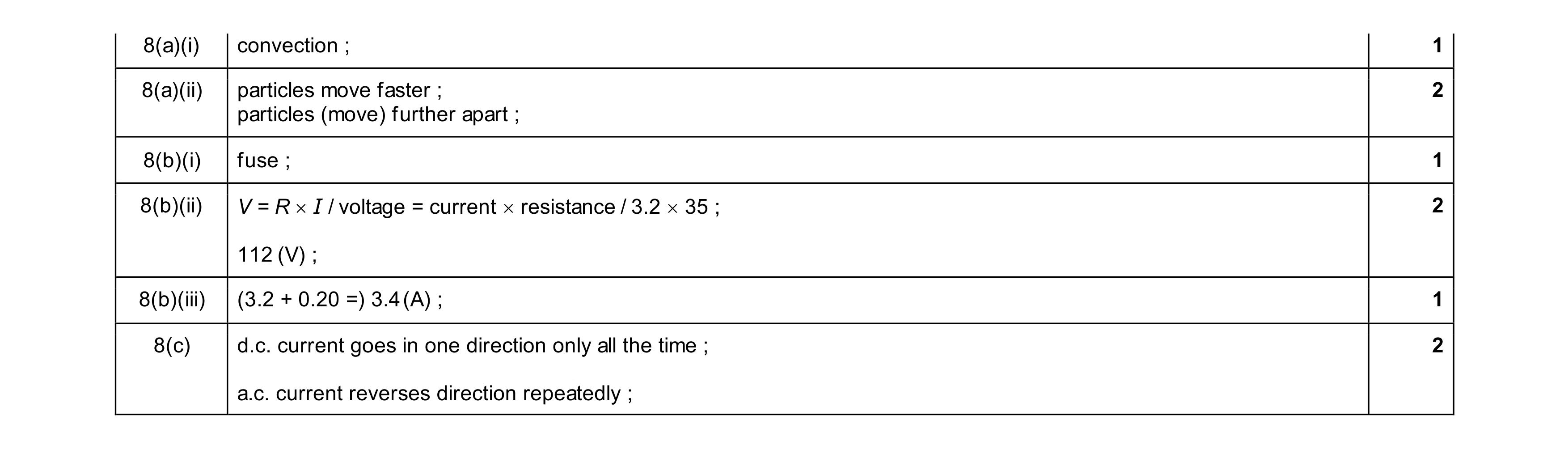 9
9