Questions as text
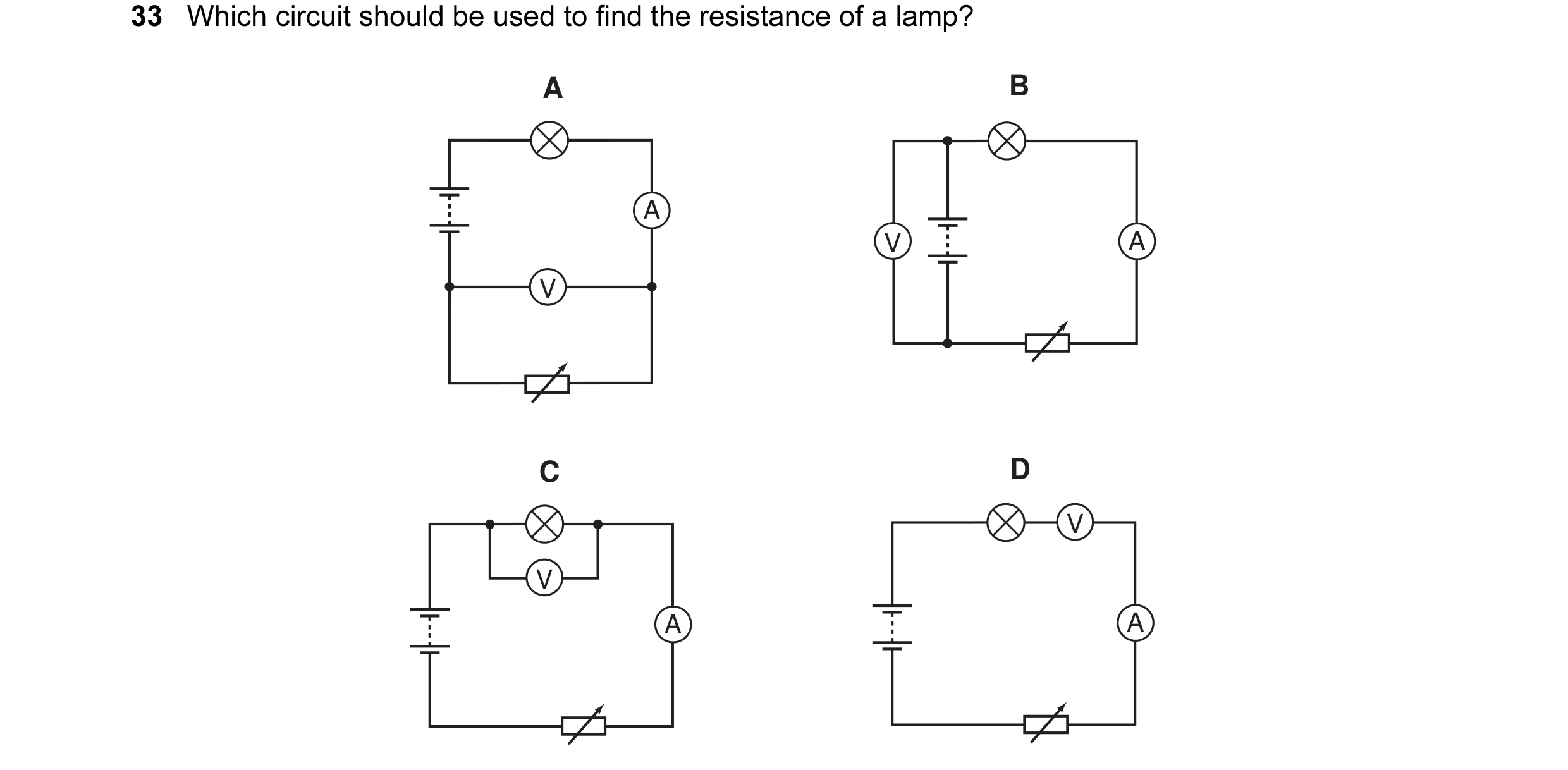
Q1 · Which circuit should be used to find the resistance of a lamp? 0652/11 Oct/Nov 2005
33 Which circuit should be used to find the resistance of a lamp? A B A V A V C D V V A A
1 marks
Answer: C
This question in 0652/11 Oct/Nov 2005
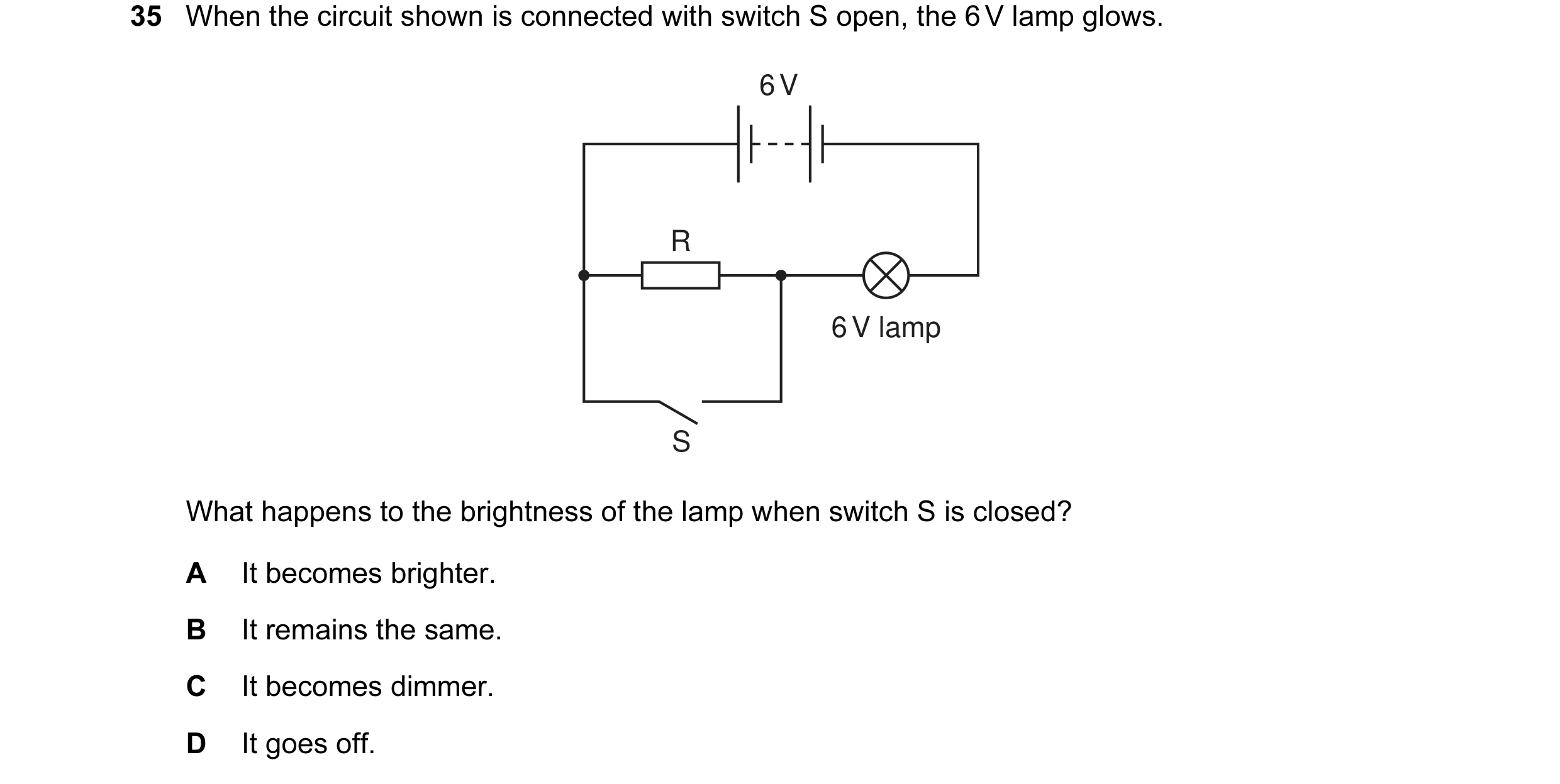
Q2 · When the circuit shown is connected with switch S open, the 6 V lamp glows 0652/11 Oct/Nov 2005
35 When the circuit shown is connected with switch S open, the 6 V lamp glows. 6 V R 6 V lamp S What happens to the brightness of the lamp when switch S is closed? A It becomes brighter. B It remains the same. C It becomes dimmer. D It goes off.
1 marks
Answer: A
This question in 0652/11 Oct/Nov 2005
Q3 · Why are the electric lamps in a house lighting circuit normally connected in parallel? 0652/11 Oct/Nov 2005
36 Why are the electric lamps in a house lighting circuit normally connected in parallel? A The current in every circuit must be the same. B The lamps are always switched on and off at the same time. C The voltage across each lamp must be the mains voltage. D When one of the lamps blows, all the others go out.
1 marks
Answer: C
This question in 0652/11 Oct/Nov 2005
Q4 · In the circuit below, one of the lamps breaks, causing all the other lamps to go out 0652/11 Oct/Nov 2006
34 In the circuit below, one of the lamps breaks, causing all the other lamps to go out. Which lamp breaks? A C D B
1 marks
Answer: D
This question in 0652/11 Oct/Nov 2006
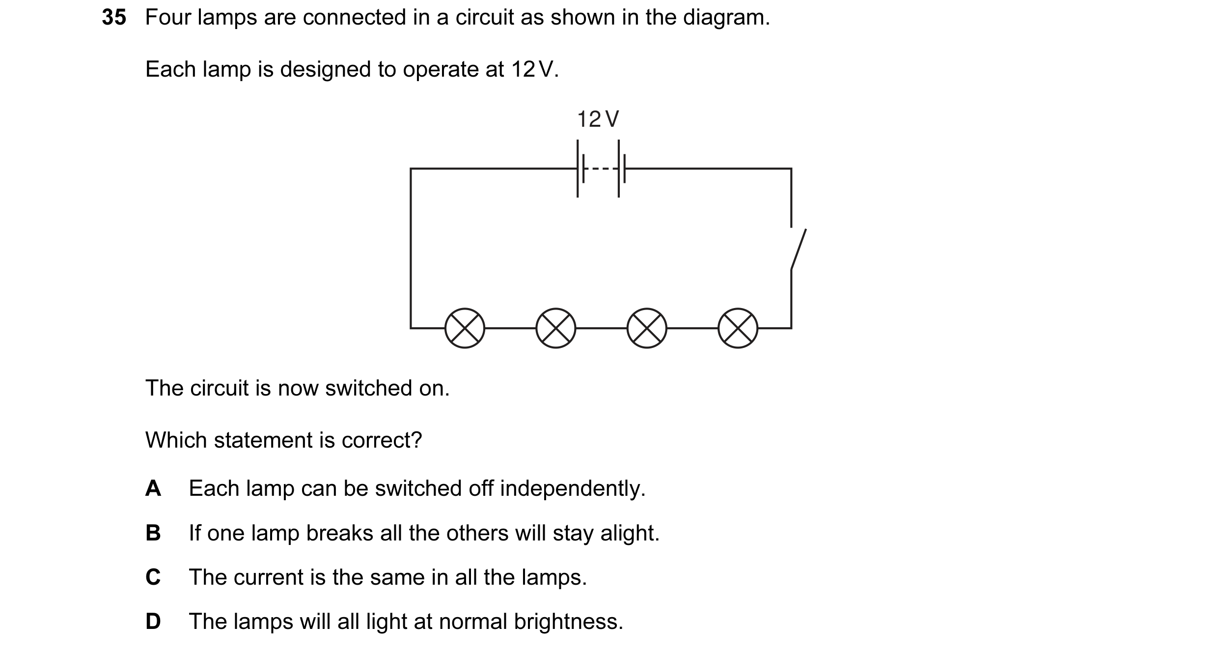
Q5 · Four lamps are connected in a circuit as shown in the diagram 0652/11 Oct/Nov 2007
35 Four lamps are connected in a circuit as shown in the diagram. Each lamp is designed to operate at 12 V. 12 V The circuit is now switched on. Which statement is correct? A Each lamp can be switched off independently. B If one lamp breaks all the others will stay alight. C The current is the same in all the lamps. D The lamps will all light at normal brightness.
1 marks
Answer: C
This question in 0652/11 Oct/Nov 2007
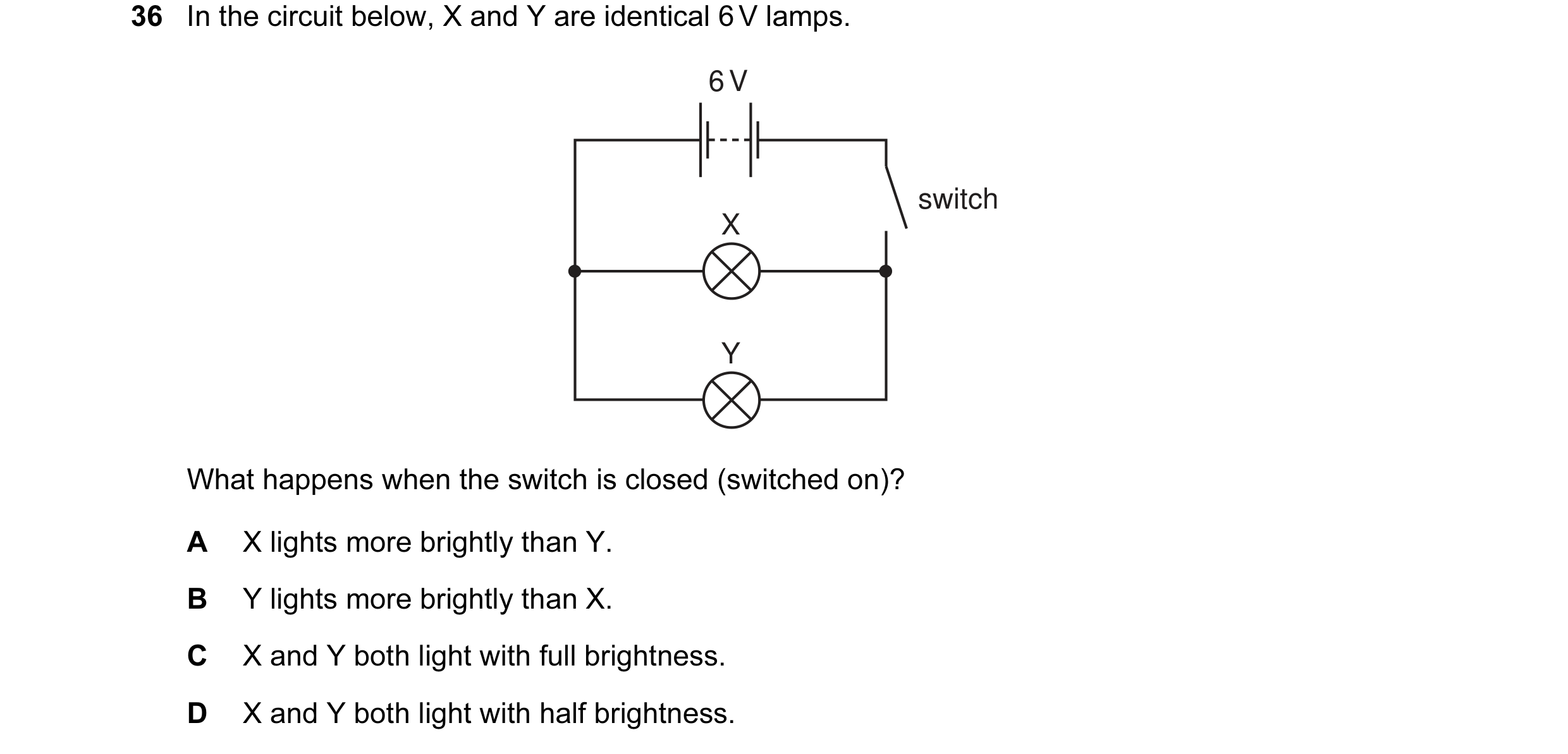
Q6 · In the circuit below, X and Y are identical 6 V lamps 0652/11 Oct/Nov 2008
36 In the circuit below, X and Y are identical 6 V lamps. 6 V switch X Y What happens when the switch is closed (switched on)? A X lights more brightly than Y. B Y lights more brightly than X. C X and Y both light with full brightness. D X and Y both light with half brightness.
1 marks
Answer: C
This question in 0652/11 Oct/Nov 2008
Q7 · The diagram shows a battery connected to two identical resistors 0652/11 Oct/Nov 2009
34 The diagram shows a battery connected to two identical resistors. Three ammeters M1, M2 and M3 are connected in the circuit. M1 A A M3 A M2 Meter M1 reads 1.0 A. What are the readings on M2 and M3? reading on M2 / A reading on M3 / A A 0.5 0.0 B 0.5 0.5 C 0.5 1.0 D 1.0 1.0
1 marks
Answer: D
This question in 0652/11 Oct/Nov 2009
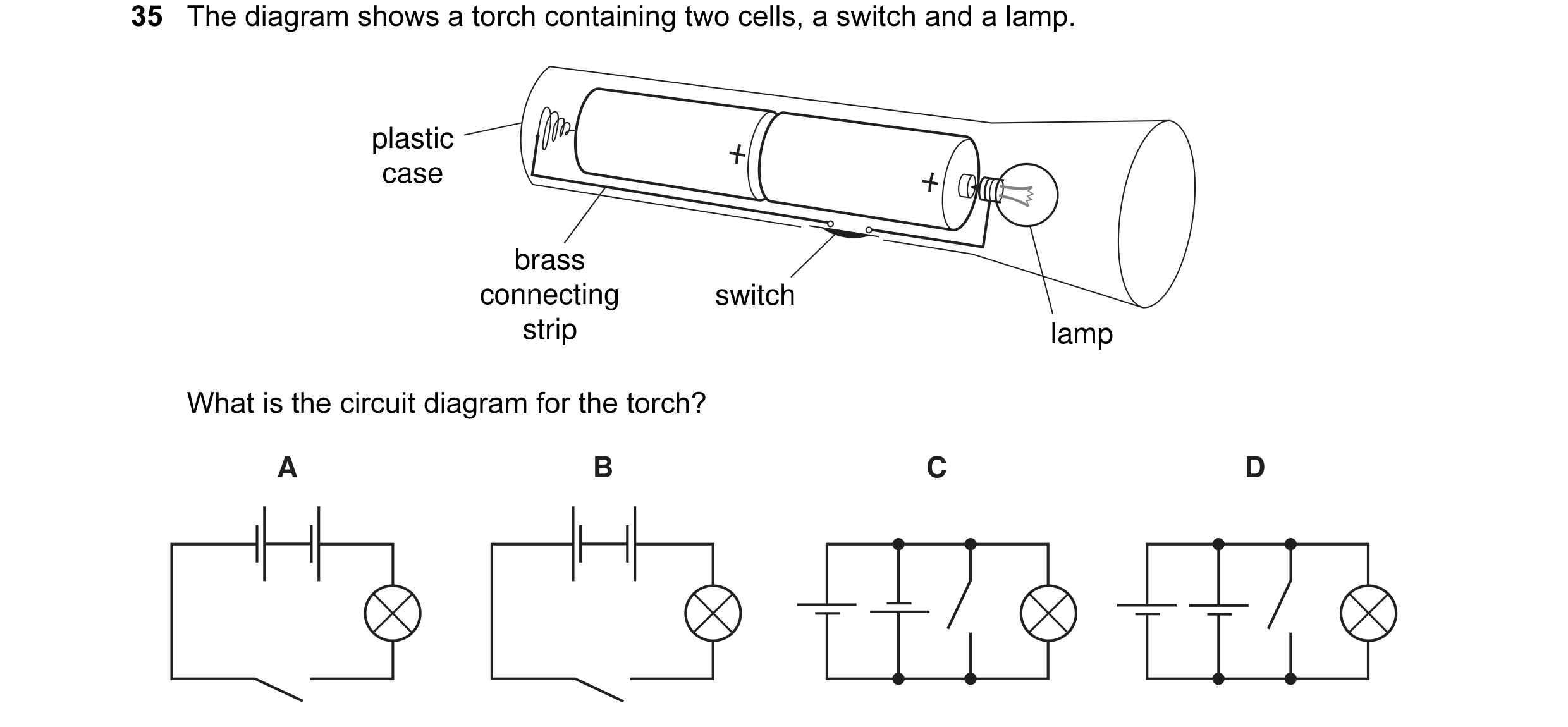
Q8 · The diagram shows a torch containing two cells, a switch and a lamp 0652/11 Oct/Nov 2009
35 The diagram shows a torch containing two cells, a switch and a lamp. plastic case brass connecting switch strip lamp What is the circuit diagram for the torch? A B C D
1 marks
Answer: A
This question in 0652/11 Oct/Nov 2009
Q9 · In a car, the headlamps H are controlled by switch X 0652/11 Oct/Nov 2010
36 In a car, the headlamps H are controlled by switch X. The foglamp F is controlled by switch Y, but only comes on if the headlamps are also switched on. Which circuit would allow all the lamps to work as above and at full brightness (12 V each)? A B H 12 V 12 V H H Y F X Y F X H C D 12 V 12 V H X X Y H F H Y F H
1 marks
Answer: D
This question in 0652/11 Oct/Nov 2010
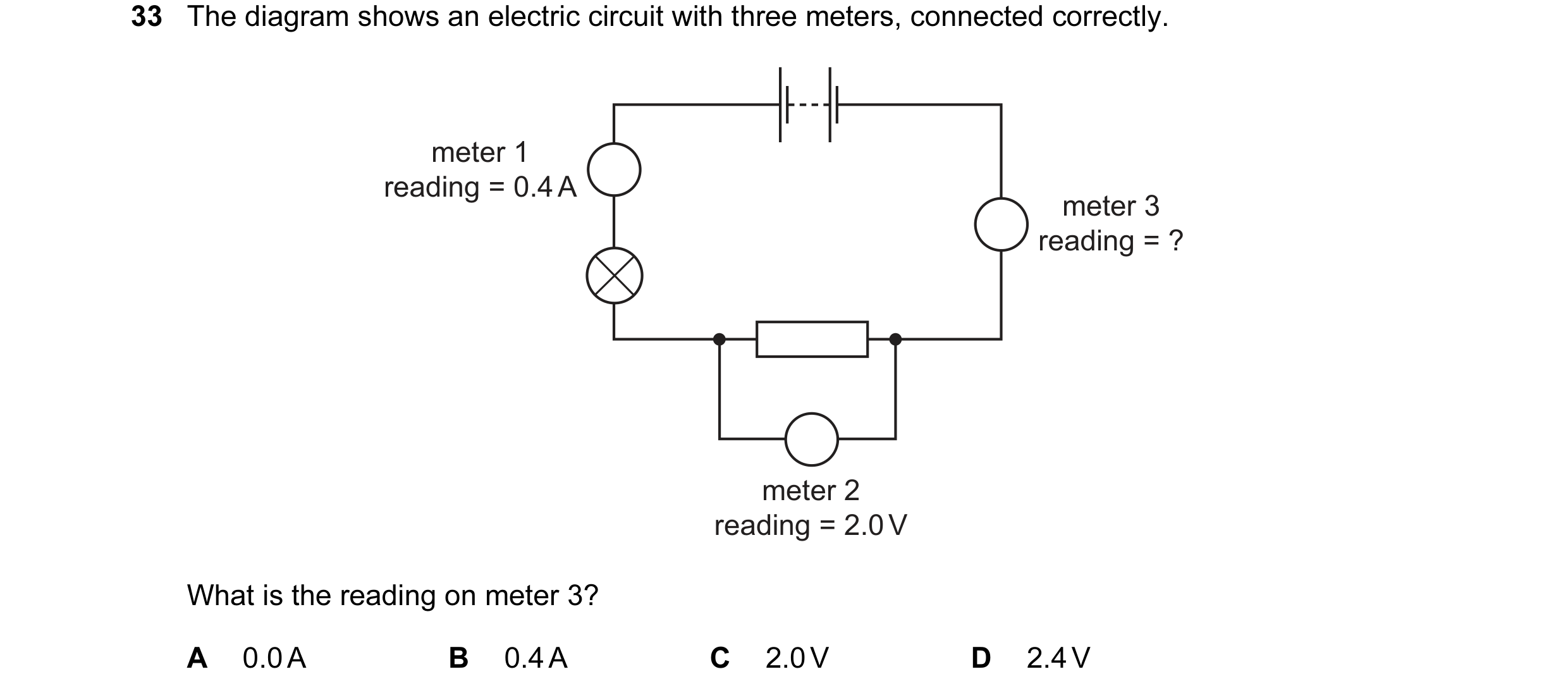
Q10 · The diagram shows an electric circuit with three meters, connected correctly 0652/11 Oct/Nov 2011
33 The diagram shows an electric circuit with three meters, connected correctly. meter 1 reading = 0.4 A meter 3 reading = ? meter 2 reading = 2.0 V What is the reading on meter 3? A 0.0 A B 0.4 A C 2.0 V D 2.4 V
1 marks
Answer: B
This question in 0652/11 Oct/Nov 2011
Q11 · The diagram shows different ways of arranging identical resistors 0652/11 Oct/Nov 2011
35 The diagram shows different ways of arranging identical resistors. Which arrangement has the smallest resistance? A B C D
1 marks
Answer: C
This question in 0652/11 Oct/Nov 2011
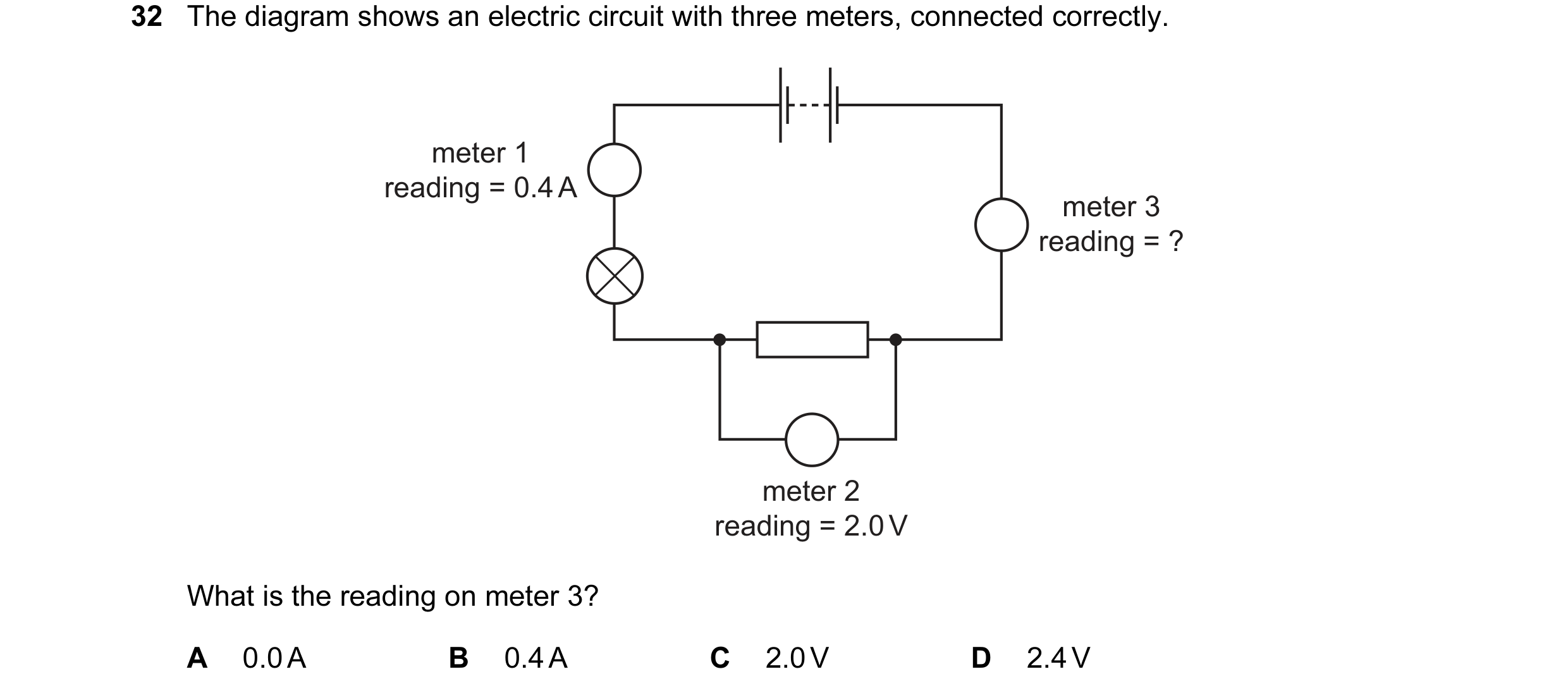
Q12 · The diagram shows an electric circuit with three meters, connected correctly 0652/12 Oct/Nov 2011
32 The diagram shows an electric circuit with three meters, connected correctly. meter 1 reading = 0.4 A meter 3 reading = ? meter 2 reading = 2.0 V What is the reading on meter 3? A 0.0 A B 0.4 A C 2.0 V D 2.4 V
1 marks
Answer: B
This question in 0652/12 Oct/Nov 2011
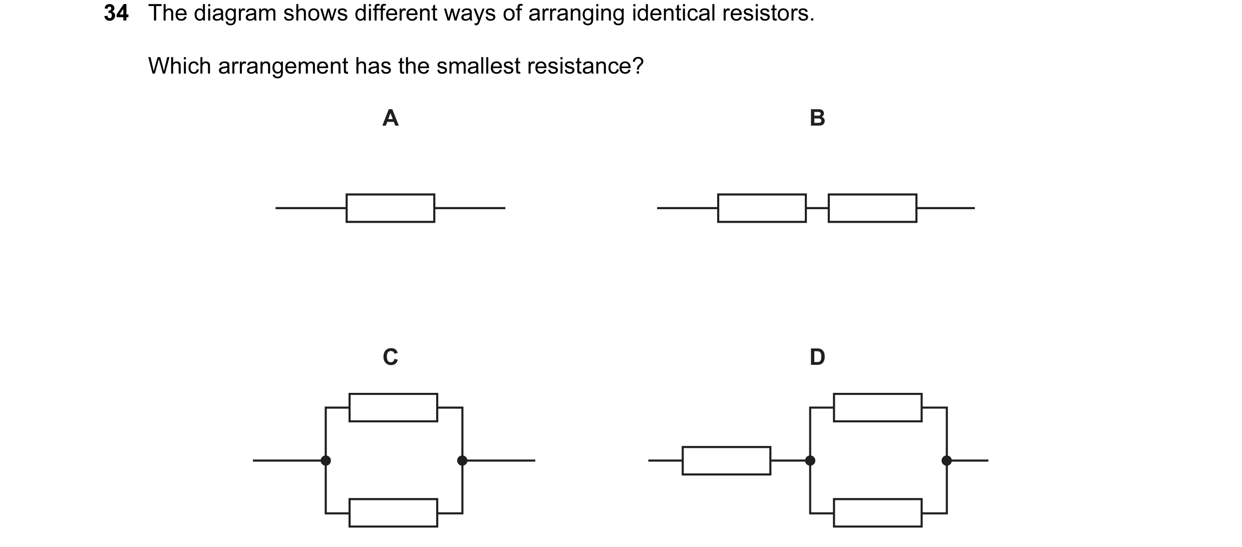
Q13 · The diagram shows different ways of arranging identical resistors 0652/12 Oct/Nov 2011
34 The diagram shows different ways of arranging identical resistors. Which arrangement has the smallest resistance? A B C D
1 marks
Answer: C
This question in 0652/12 Oct/Nov 2011
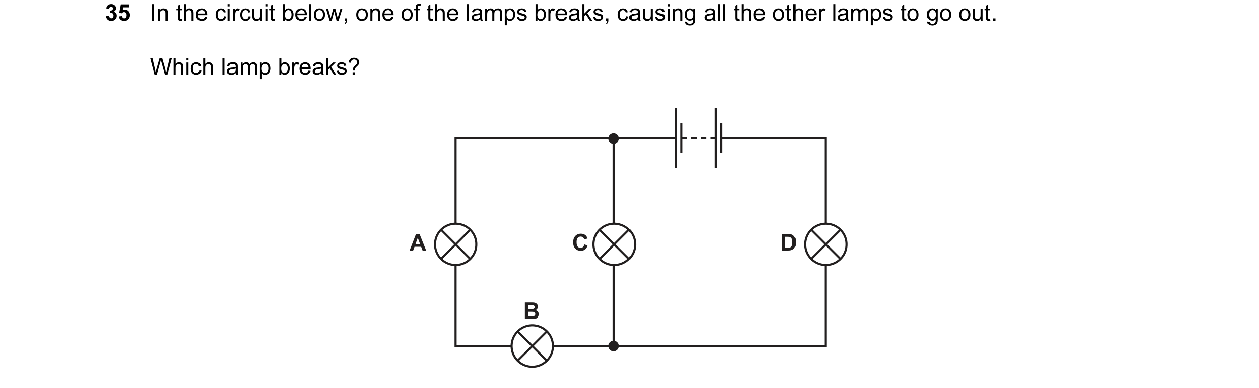
Q14 · In the circuit below, one of the lamps breaks, causing all the other lamps to go out 0652/11 Oct/Nov 2013
35 In the circuit below, one of the lamps breaks, causing all the other lamps to go out. Which lamp breaks? A C D B
1 marks
Answer: D
This question in 0652/11 Oct/Nov 2013
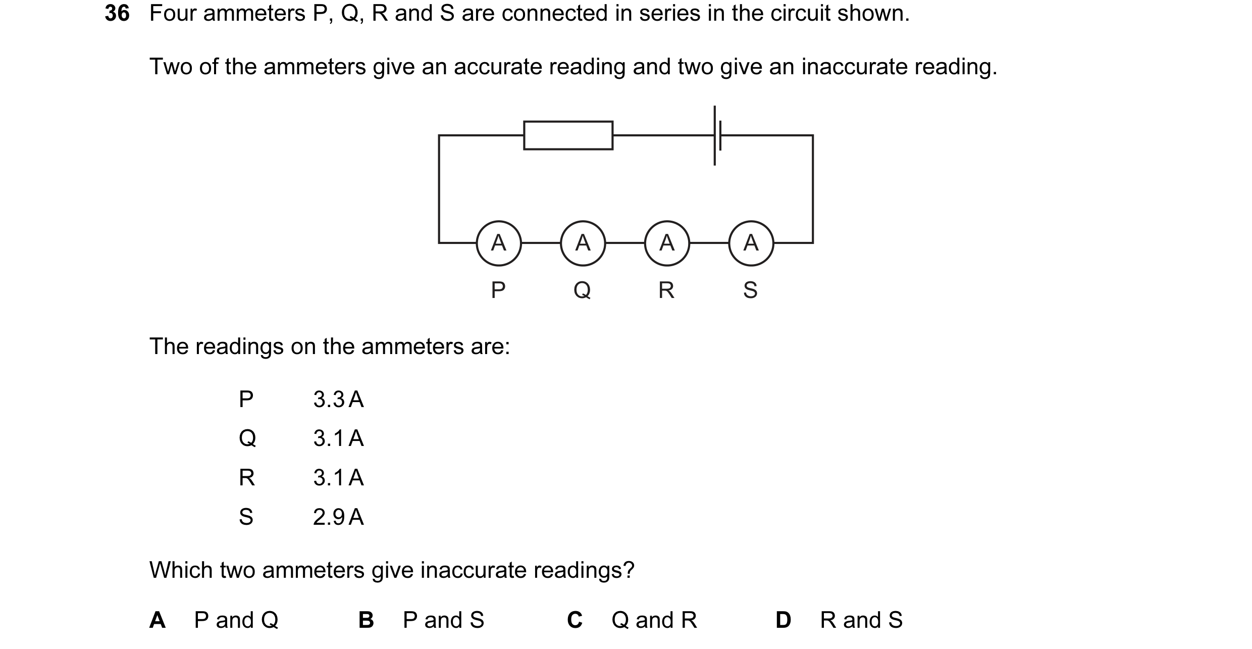
Q15 · Four ammeters P, Q, R and S are connected in series in the circuit shown 0652/11 Oct/Nov 2013
36 Four ammeters P, Q, R and S are connected in series in the circuit shown. Two of the ammeters give an accurate reading and two give an inaccurate reading. A A A A P Q R S The readings on the ammeters are: P 3.3 A Q 3.1 A R 3.1 A S 2.9 A Which two ammeters give inaccurate readings? A P and Q B P and S C Q and R D R and S
1 marks
Answer: B
This question in 0652/11 Oct/Nov 2013
Q16 · In the circuit below, one of the lamps breaks, causing all the other lamps to go out 0652/12 Oct/Nov 2013
35 In the circuit below, one of the lamps breaks, causing all the other lamps to go out. Which lamp breaks? A C D B
1 marks
Answer: D
This question in 0652/12 Oct/Nov 2013
Q17 · Four ammeters P, Q, R and S are connected in series in the circuit shown 0652/12 Oct/Nov 2013
36 Four ammeters P, Q, R and S are connected in series in the circuit shown. Two of the ammeters give an accurate reading and two give an inaccurate reading. A A A A P Q R S The readings on the ammeters are: P 3.3 A Q 3.1 A R 3.1 A S 2.9 A Which two ammeters give inaccurate readings? A P and Q B P and S C Q and R D R and S
1 marks
Answer: B
This question in 0652/12 Oct/Nov 2013
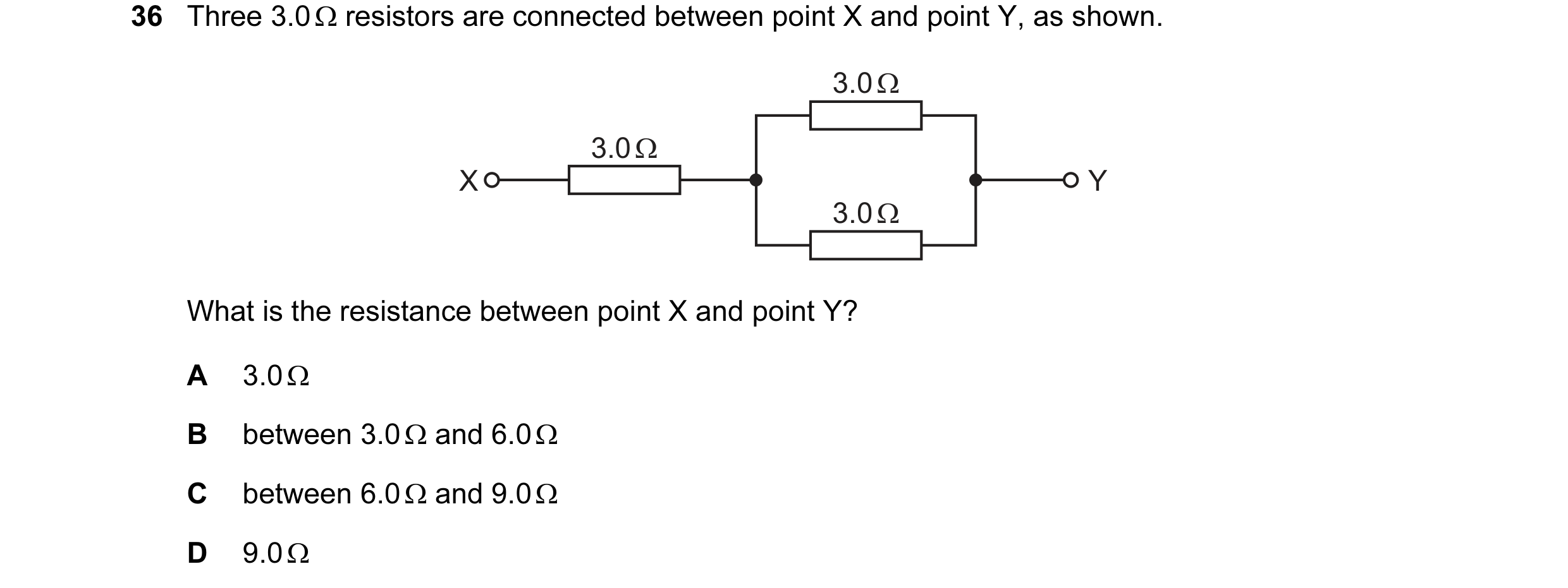
Q18 · Three 3.0 Ω resistors are connected between point X and point Y, as shown 0652/11 Oct/Nov 2014
36 Three 3.0 Ω resistors are connected between point X and point Y, as shown. 3.0 Ω 3.0 Ω X Y 3.0 Ω What is the resistance between point X and point Y? A 3.0 Ω B between 3.0 Ω and 6.0 Ω C between 6.0 Ω and 9.0 Ω D 9.0 Ω
1 marks
Answer: B
This question in 0652/11 Oct/Nov 2014
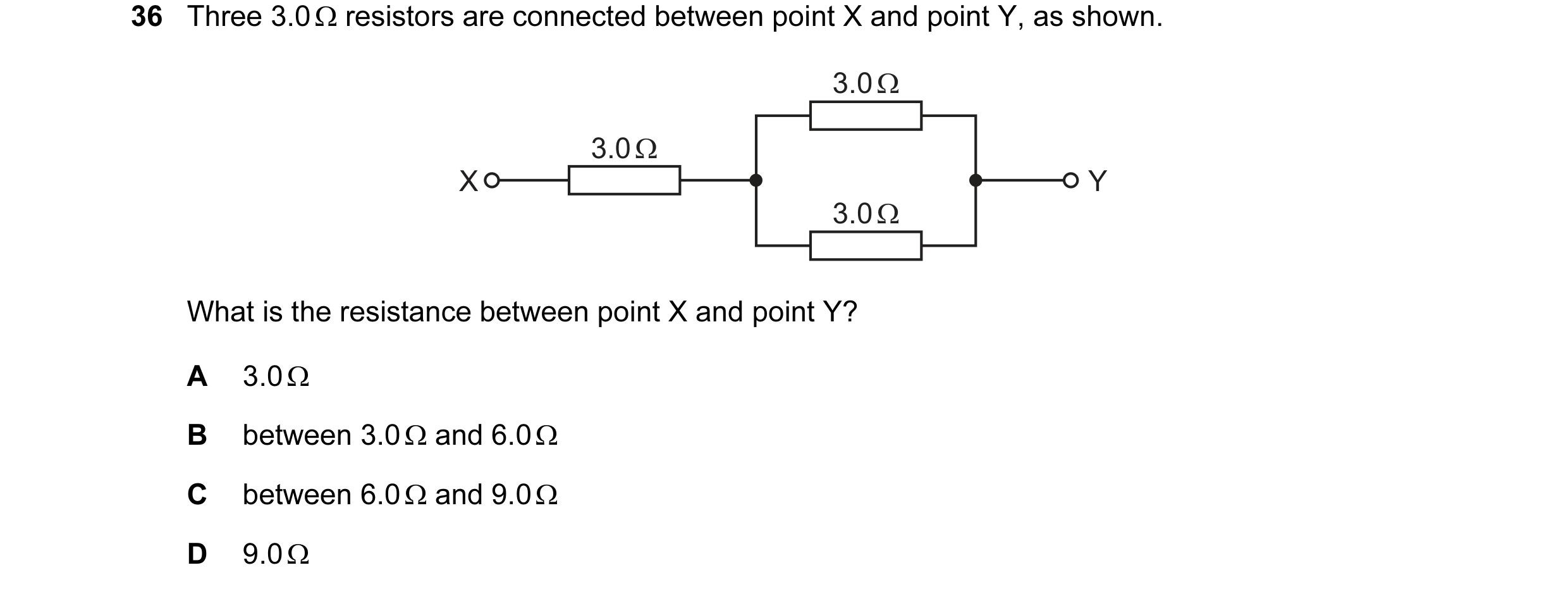
Q19 · Three 3.0 Ω resistors are connected between point X and point Y, as shown 0652/12 Oct/Nov 2014
36 Three 3.0 Ω resistors are connected between point X and point Y, as shown. 3.0 Ω 3.0 Ω X Y 3.0 Ω What is the resistance between point X and point Y? A 3.0 Ω B between 3.0 Ω and 6.0 Ω C between 6.0 Ω and 9.0 Ω D 9.0 Ω
1 marks
Answer: B
This question in 0652/12 Oct/Nov 2014
Q20 · The diagrams show two electric circuits 0652/11 Oct/Nov 2015
36 The diagrams show two electric circuits. Circuit 1 contains a cell, an ammeter and a resistor. A second resistor is now connected to circuit 1, to make circuit 2. A A circuit 1 circuit 2 Which circuit has the smaller total resistance and in which circuit is the ammeter reading smaller? smaller smaller total reading on resistance ammeter A circuit 1 circuit 1 B circuit 1 circuit 2 C circuit 2 circuit 1 D circuit 2 circuit 2
1 marks
Answer: C
This question in 0652/11 Oct/Nov 2015
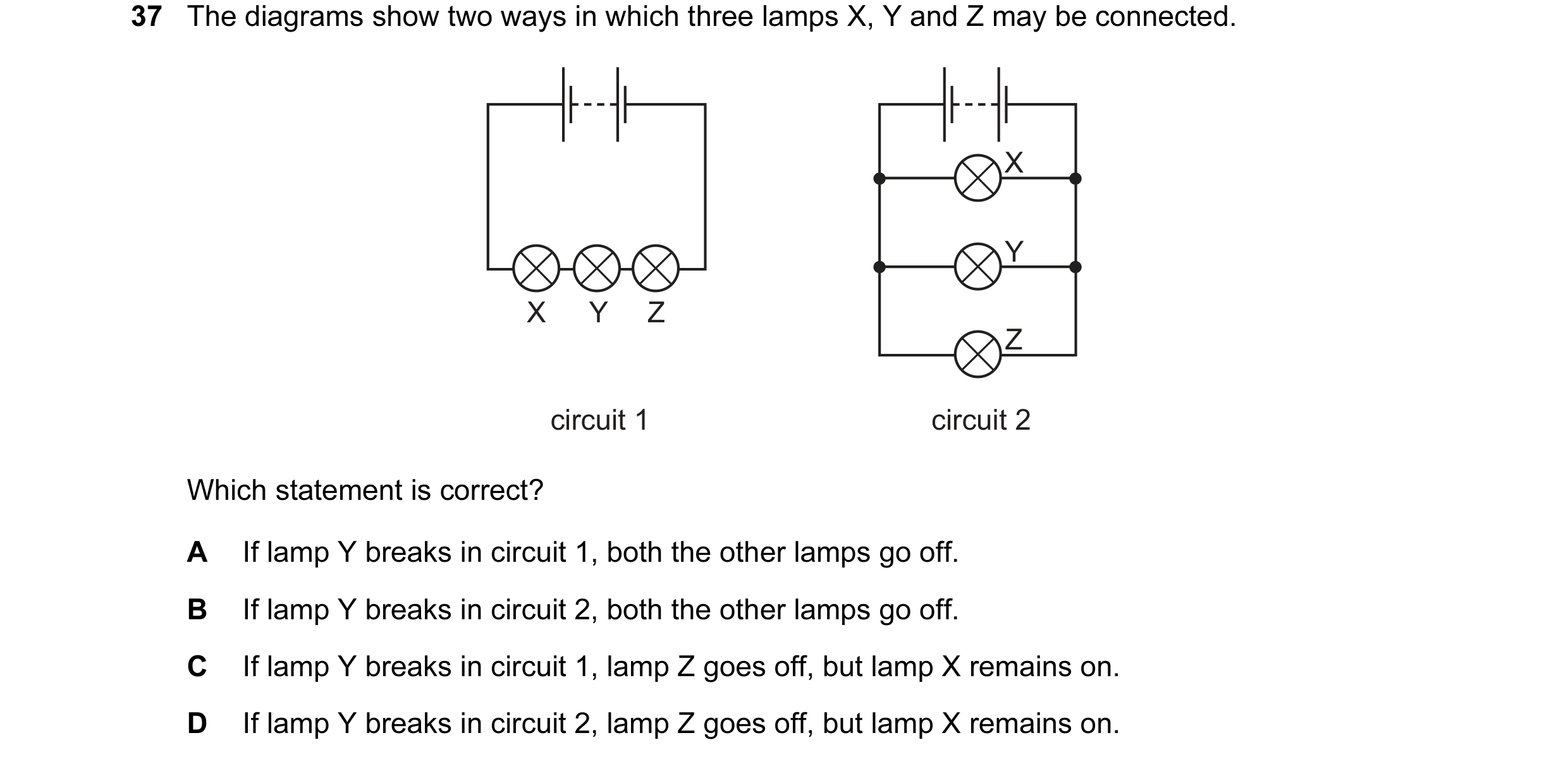
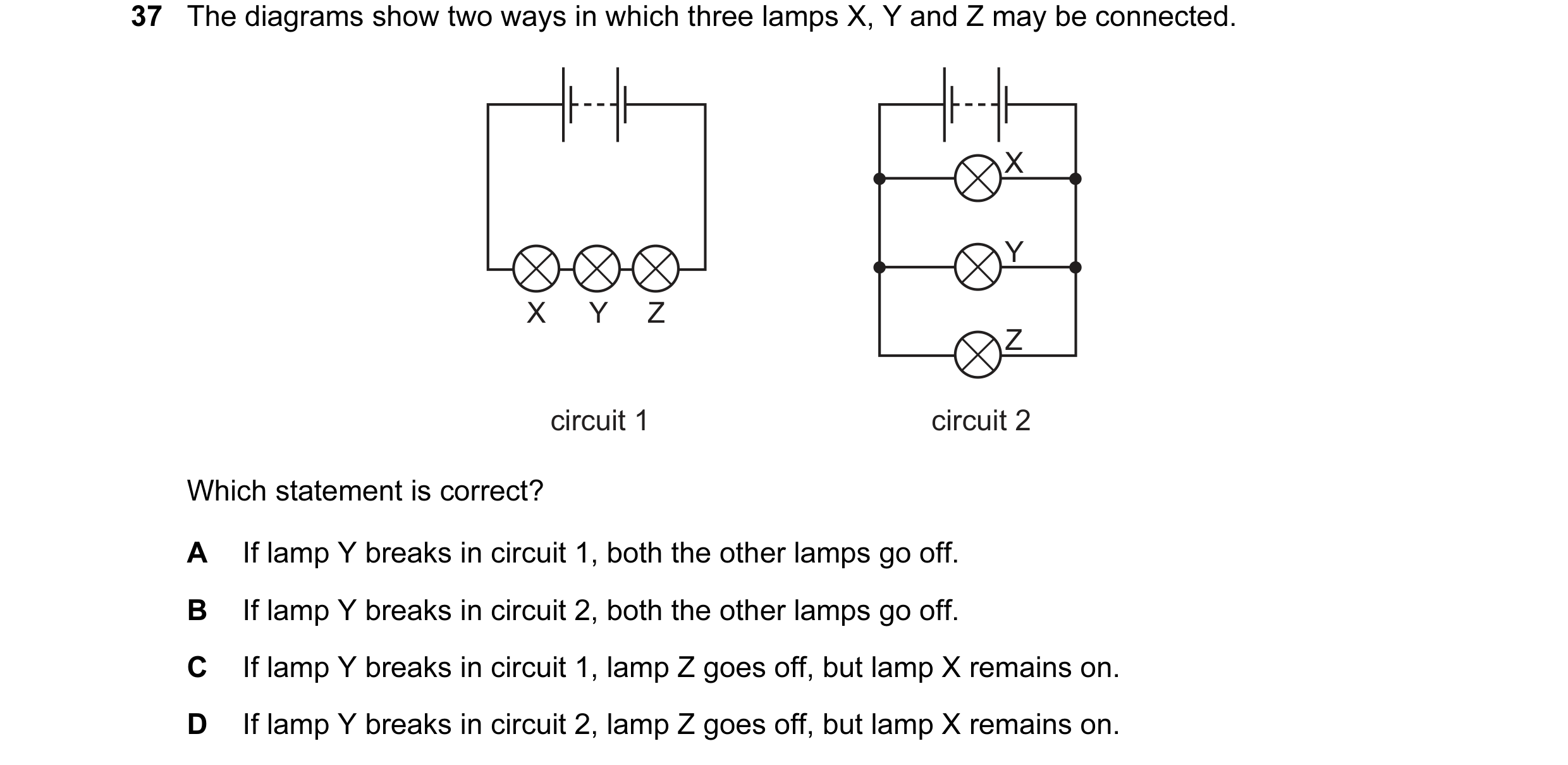
Q21 · The diagrams show two ways in which three lamps X, Y and Z may be connected 0652/11 Oct/Nov 2015
37 The diagrams show two ways in which three lamps X, Y and Z may be connected. X Y X Y Z Z circuit 1 circuit 2 Which statement is correct? A If lamp Y breaks in circuit 1, both the other lamps go off. B If lamp Y breaks in circuit 2, both the other lamps go off. C If lamp Y breaks in circuit 1, lamp Z goes off, but lamp X remains on. D If lamp Y breaks in circuit 2, lamp Z goes off, but lamp X remains on.
1 marks
Answer: A
This question in 0652/11 Oct/Nov 2015
Q22 · The diagrams show two electric circuits 0652/12 Oct/Nov 2015
36 The diagrams show two electric circuits. Circuit 1 contains a cell, an ammeter and a resistor. A second resistor is now connected to circuit 1, to make circuit 2. A A circuit 1 circuit 2 Which circuit has the smaller total resistance and in which circuit is the ammeter reading smaller? smaller smaller total reading on resistance ammeter A circuit 1 circuit 1 B circuit 1 circuit 2 C circuit 2 circuit 1 D circuit 2 circuit 2
1 marks
Answer: C
This question in 0652/12 Oct/Nov 2015
Q23 · The diagrams show two ways in which three lamps X, Y and Z may be connected 0652/12 Oct/Nov 2015
37 The diagrams show two ways in which three lamps X, Y and Z may be connected. X Y X Y Z Z circuit 1 circuit 2 Which statement is correct? A If lamp Y breaks in circuit 1, both the other lamps go off. B If lamp Y breaks in circuit 2, both the other lamps go off. C If lamp Y breaks in circuit 1, lamp Z goes off, but lamp X remains on. D If lamp Y breaks in circuit 2, lamp Z goes off, but lamp X remains on.
1 marks
Answer: A
This question in 0652/12 Oct/Nov 2015
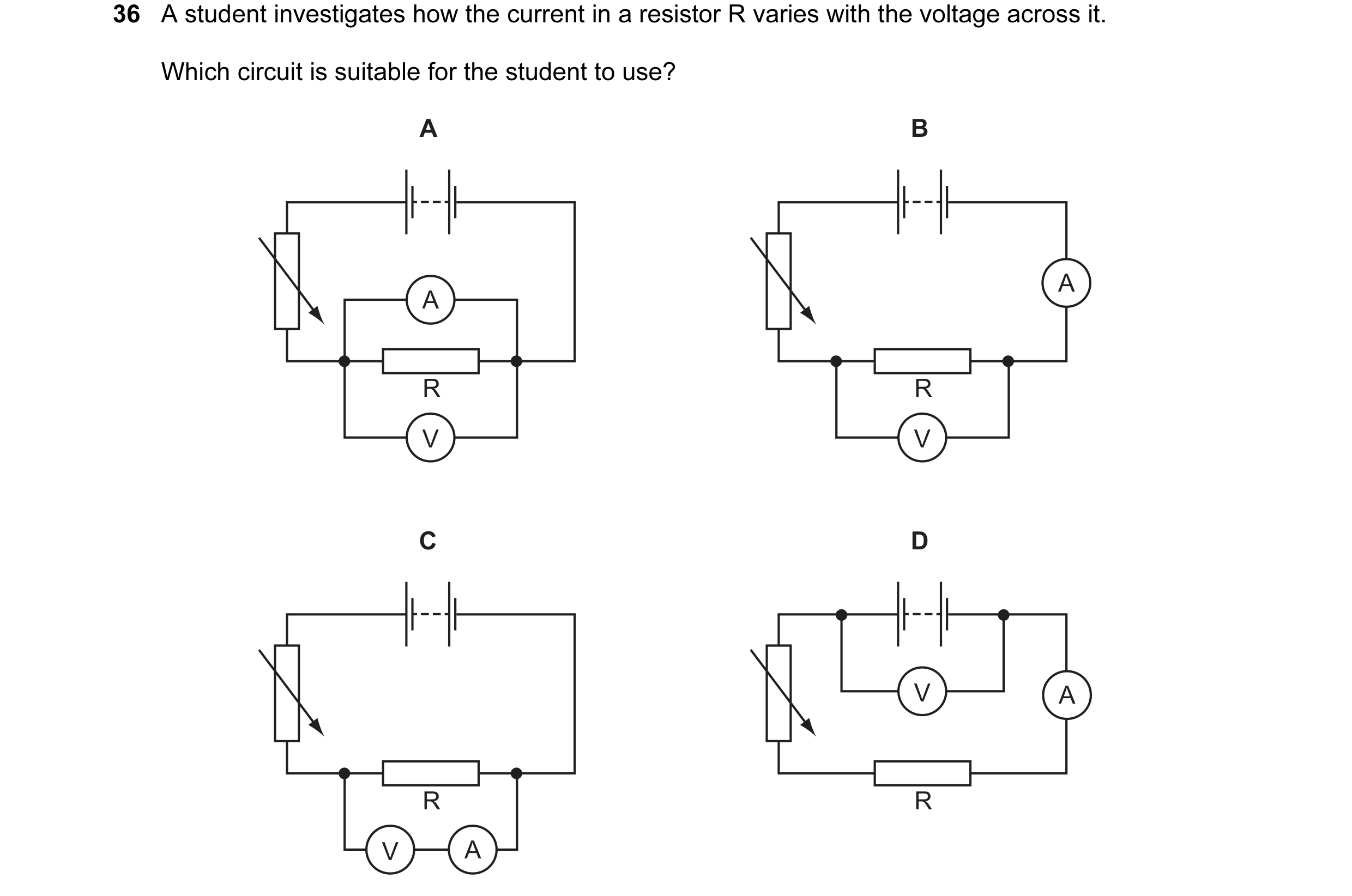
Q24 · A student investigates how the current in a resistor R varies with the voltage across it 0652/11 Oct/Nov 2016
36 A student investigates how the current in a resistor R varies with the voltage across it. Which circuit is suitable for the student to use? A B A A R R V V C D V A R R V A
1 marks
Answer: B
This question in 0652/11 Oct/Nov 2016
Q25 · A student investigates how the current in a resistor R varies with the voltage across it 0652/12 Oct/Nov 2016
36 A student investigates how the current in a resistor R varies with the voltage across it. Which circuit is suitable for the student to use? A B A A R R V V C D V A R R V A
1 marks
Answer: B
This question in 0652/12 Oct/Nov 2016
Q26 · The circuit shown is used to determine the resistance of resistor R 0652/11 Oct/Nov 2017
35 The circuit shown is used to determine the resistance of resistor R. P and Q are two meters, connected correctly. meter P R meter Q Which calculation gives the value of R? A (reading of meter P) ÷ (reading of meter Q) B (reading of meter P) × (reading of meter Q) C (reading of meter Q) + (reading of meter P) D (reading of meter Q) ÷ (reading of meter P)
1 marks
Answer: D
This question in 0652/11 Oct/Nov 2017
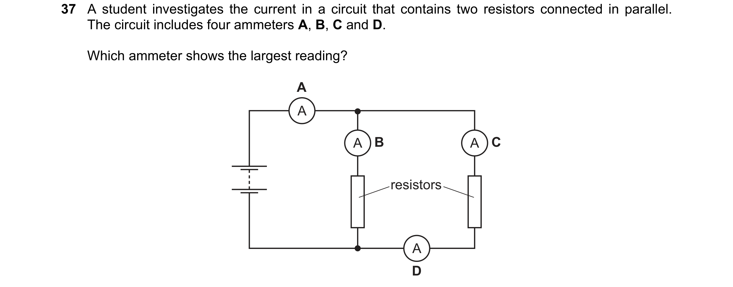
Q27 · A student investigates the current in a circuit that contains two resistors connected in… 0652/11 Oct/Nov 2017
37 A student investigates the current in a circuit that contains two resistors connected in parallel. The circuit includes four ammeters A, B, C and D. Which ammeter shows the largest reading? A A A B A C resistors A D
1 marks
Answer: A
This question in 0652/11 Oct/Nov 2017
Q28 · The circuit shown is used to determine the resistance of resistor R 0652/12 Oct/Nov 2017
35 The circuit shown is used to determine the resistance of resistor R. P and Q are two meters, connected correctly. meter P R meter Q Which calculation gives the value of R? A (reading of meter P) ÷ (reading of meter Q) B (reading of meter P) × (reading of meter Q) C (reading of meter Q) + (reading of meter P) D (reading of meter Q) ÷ (reading of meter P)
1 marks
Answer: D
This question in 0652/12 Oct/Nov 2017
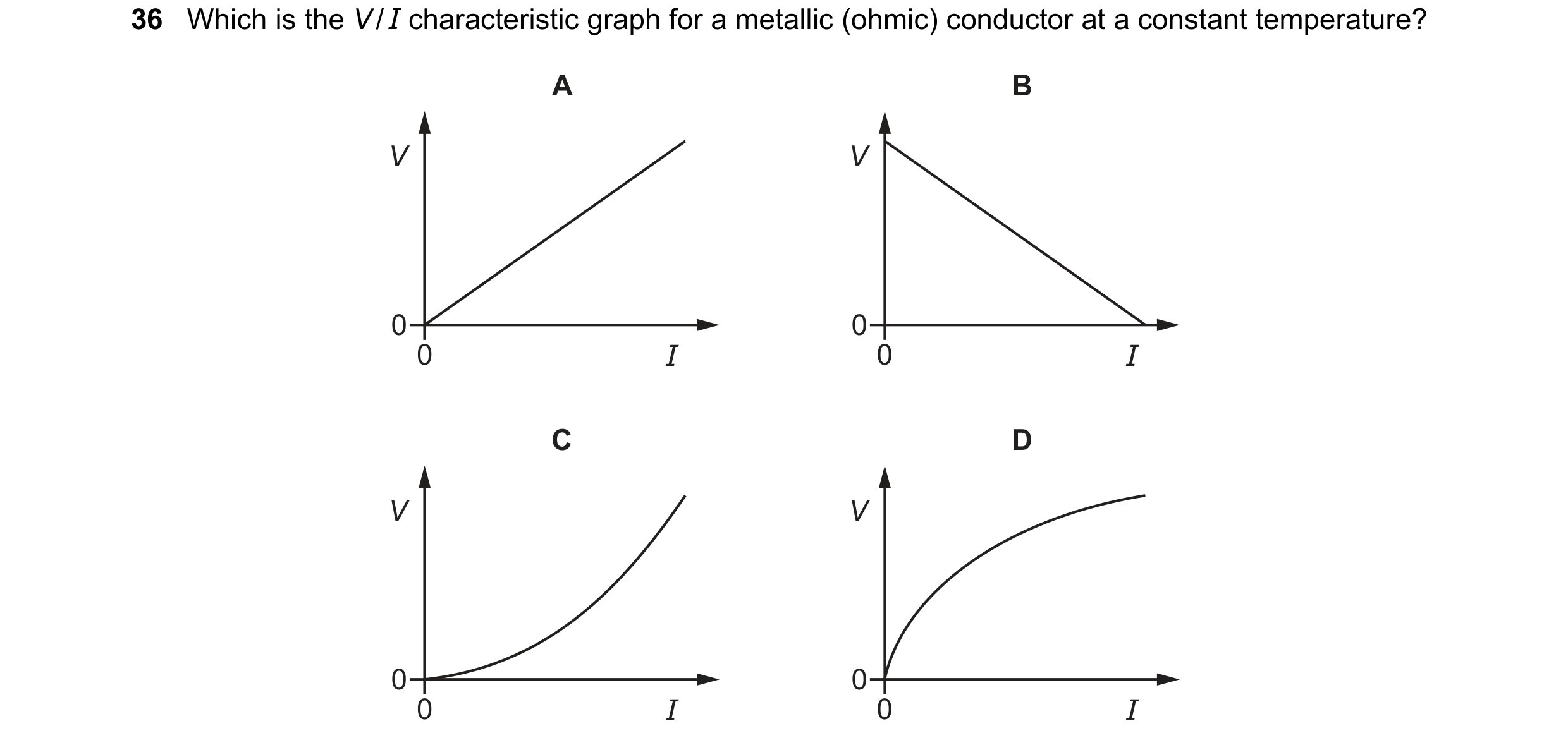
Q29 · Which is the V / I characteristic graph for a metallic (ohmic) conductor at a constant… 0652/12 Oct/Nov 2017
36 Which is the V / I characteristic graph for a metallic (ohmic) conductor at a constant temperature? A B V V 0 0 0 I 0 I C D V V 0 0 0 I 0 I
1 marks
Answer: A
This question in 0652/12 Oct/Nov 2017
Q30 · A student investigates the current in a circuit that contains two resistors connected in… 0652/12 Oct/Nov 2017
37 A student investigates the current in a circuit that contains two resistors connected in parallel. The circuit includes four ammeters A, B, C and D. Which ammeter shows the largest reading? A A A B A C resistors A D
1 marks
Answer: A
This question in 0652/12 Oct/Nov 2017
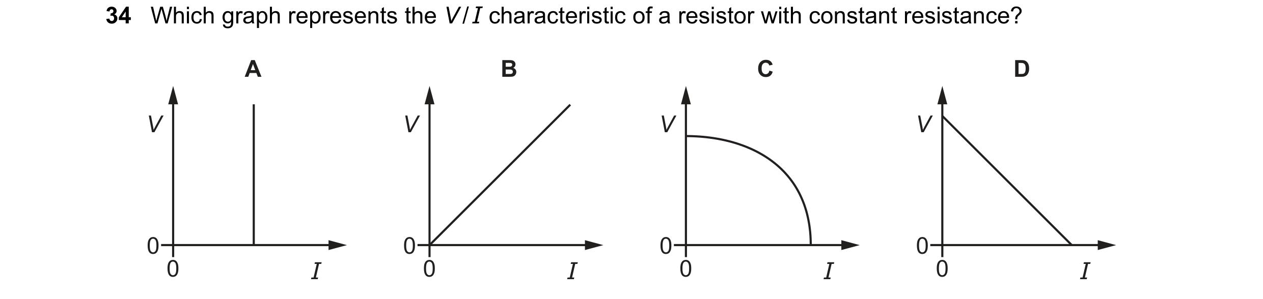
Q31 · Which graph represents the V / I characteristic of a resistor with constant resistance? 0652/11 Oct/Nov 2018
34 Which graph represents the V / I characteristic of a resistor with constant resistance? A B C D V V V V 0 0 0 0 0 I 0 I 0 I 0 I
1 marks
Answer: B
This question in 0652/11 Oct/Nov 2018
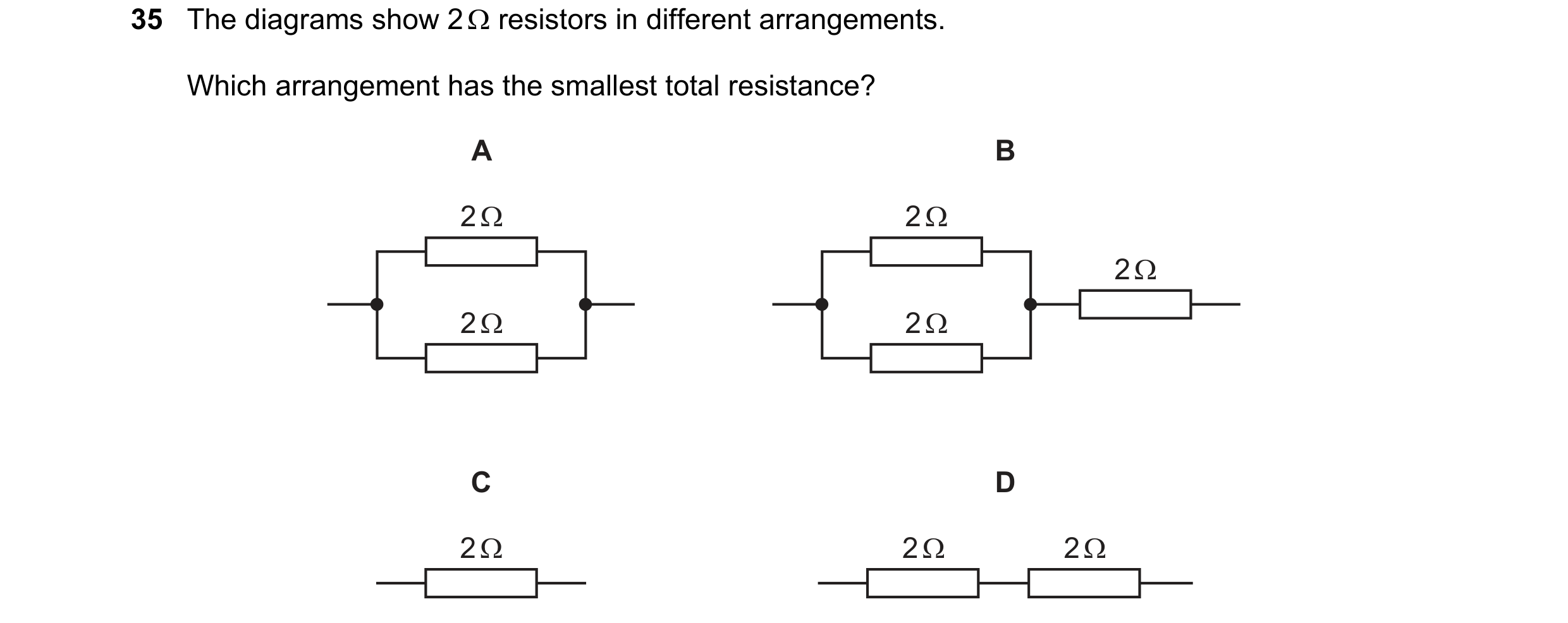
Q32 · The diagrams show 2 Ω resistors in different arrangements 0652/11 Oct/Nov 2018
35 The diagrams show 2 Ω resistors in different arrangements. Which arrangement has the smallest total resistance? A B 2 Ω 2 Ω 2 Ω 2 Ω 2 Ω C D 2 Ω 2 Ω 2 Ω
1 marks
Answer: A
This question in 0652/11 Oct/Nov 2018
Q33 · The diagrams show 2 Ω resistors in different arrangements 0652/12 Oct/Nov 2018
35 The diagrams show 2 Ω resistors in different arrangements. Which arrangement has the smallest total resistance? A B 2 Ω 2 Ω 2 Ω 2 Ω 2 Ω C D 2 Ω 2 Ω 2 Ω
1 marks
Answer: A
This question in 0652/12 Oct/Nov 2018
Q34 · Which diagram shows a meter being used to measure the potential difference across a… 0652/11 Oct/Nov 2019
33 Which diagram shows a meter being used to measure the potential difference across a resistor? A B C D A V A V
1 marks
Answer: A
This question in 0652/11 Oct/Nov 2019
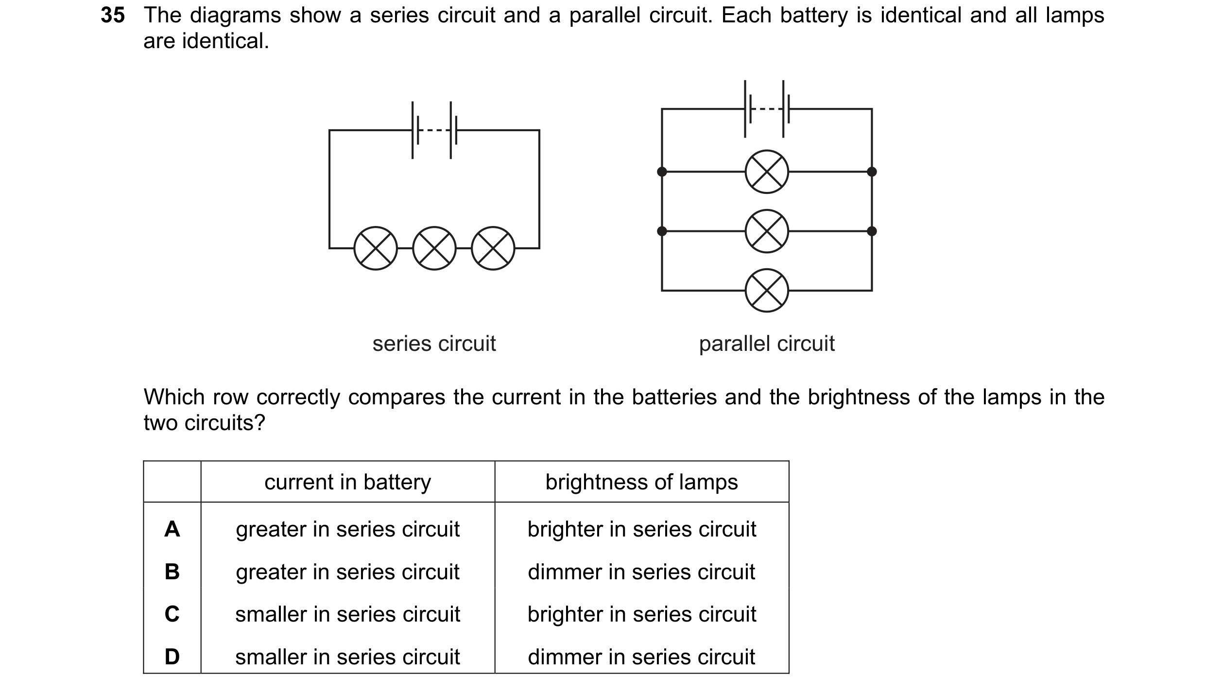
Q35 · The diagrams show a series circuit and a parallel circuit 0652/11 Oct/Nov 2019
35 The diagrams show a series circuit and a parallel circuit. Each battery is identical and all lamps are identical. series circuit parallel circuit Which row correctly compares the current in the batteries and the brightness of the lamps in the two circuits? current in battery brightness of lamps A greater in series circuit brighter in series circuit B greater in series circuit dimmer in series circuit C smaller in series circuit brighter in series circuit D smaller in series circuit dimmer in series circuit
1 marks
Answer: D
This question in 0652/11 Oct/Nov 2019
Q36 · A 20 Ω resistor and a 10 Ω resistor are connected in parallel 0652/11 Oct/Nov 2019
36 A 20 Ω resistor and a 10 Ω resistor are connected in parallel. 20 Ω 10 Ω What is their combined resistance? A less than 10 Ω B 10 Ω C 20 Ω D more than 20 Ω
1 marks
Answer: A
This question in 0652/11 Oct/Nov 2019
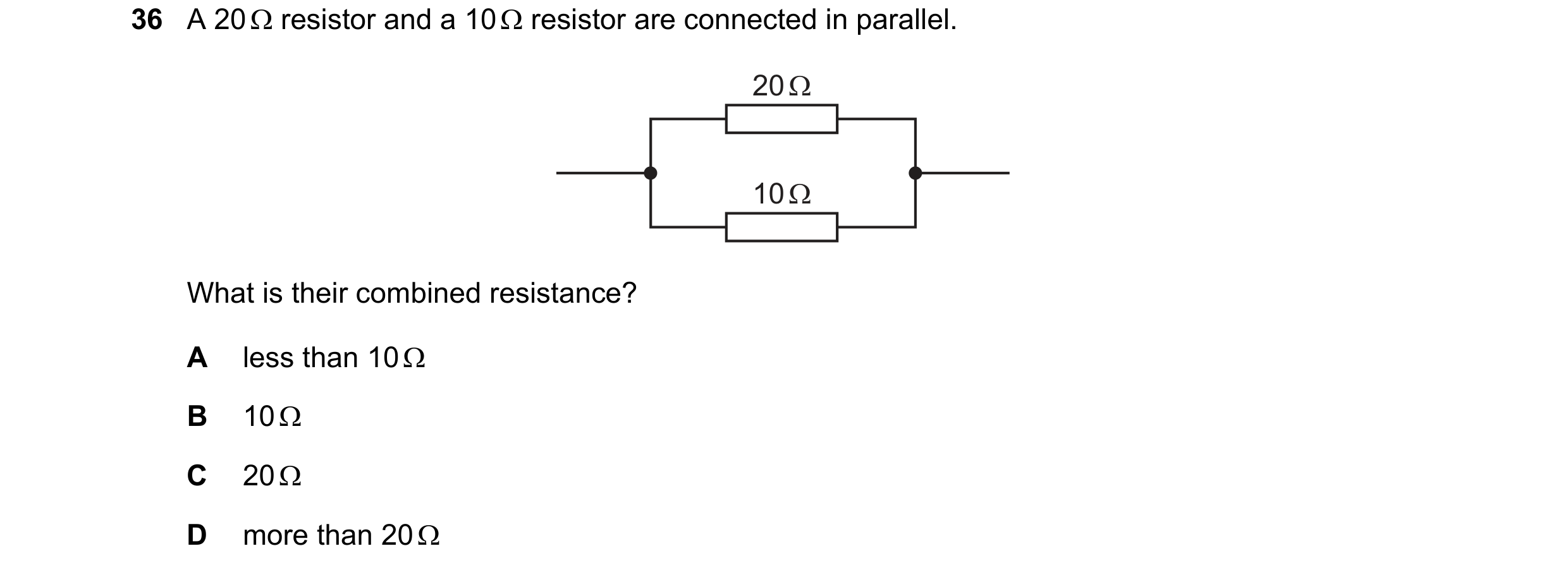
Q37 · A 20 Ω resistor and a 10 Ω resistor are connected in parallel 0652/12 Oct/Nov 2019
36 A 20 Ω resistor and a 10 Ω resistor are connected in parallel. 20 Ω 10 Ω What is their combined resistance? A less than 10 Ω B 10 Ω C 20 Ω D more than 20 Ω
1 marks
Answer: A
This question in 0652/12 Oct/Nov 2019
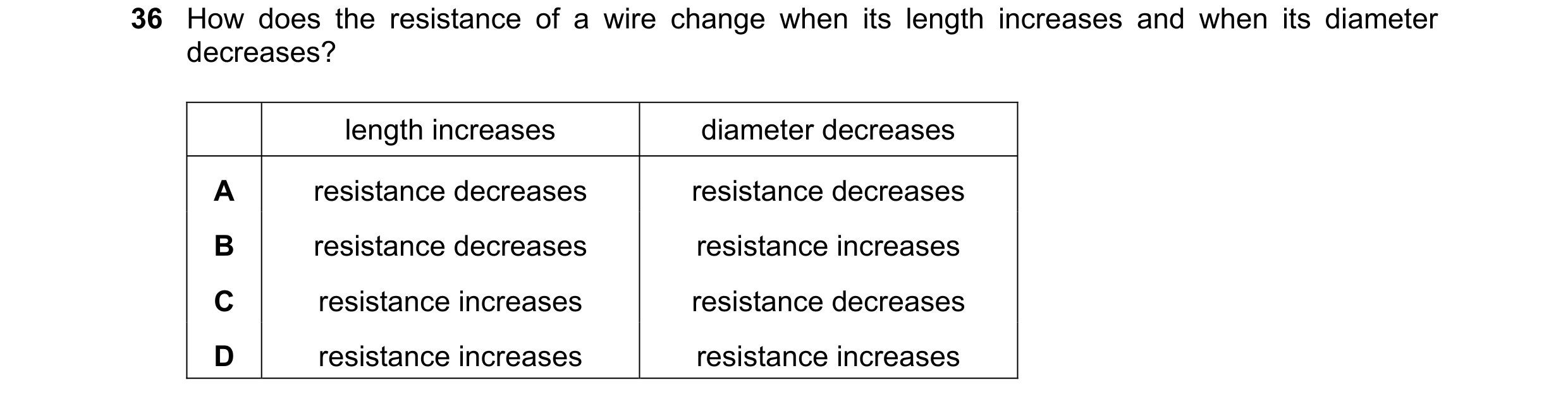
Q38 · How does the resistance of a wire change when its length increases and when its diameter… 0652/11 Oct/Nov 2020
36 How does the resistance of a wire change when its length increases and when its diameter decreases? length increases diameter decreases A resistance decreases resistance decreases B resistance decreases resistance increases C resistance increases resistance decreases D resistance increases resistance increases
1 marks
Answer: D
This question in 0652/11 Oct/Nov 2020
Q39 · Four 240 V lamps are to be powered by a 240 V supply 0652/11 Oct/Nov 2020
37 Four 240 V lamps are to be powered by a 240 V supply. Which circuit allows all four lamps to light at full brightness? A B 240 V 240 V C D 240 V 240 V
1 marks
Answer: C
This question in 0652/11 Oct/Nov 2020
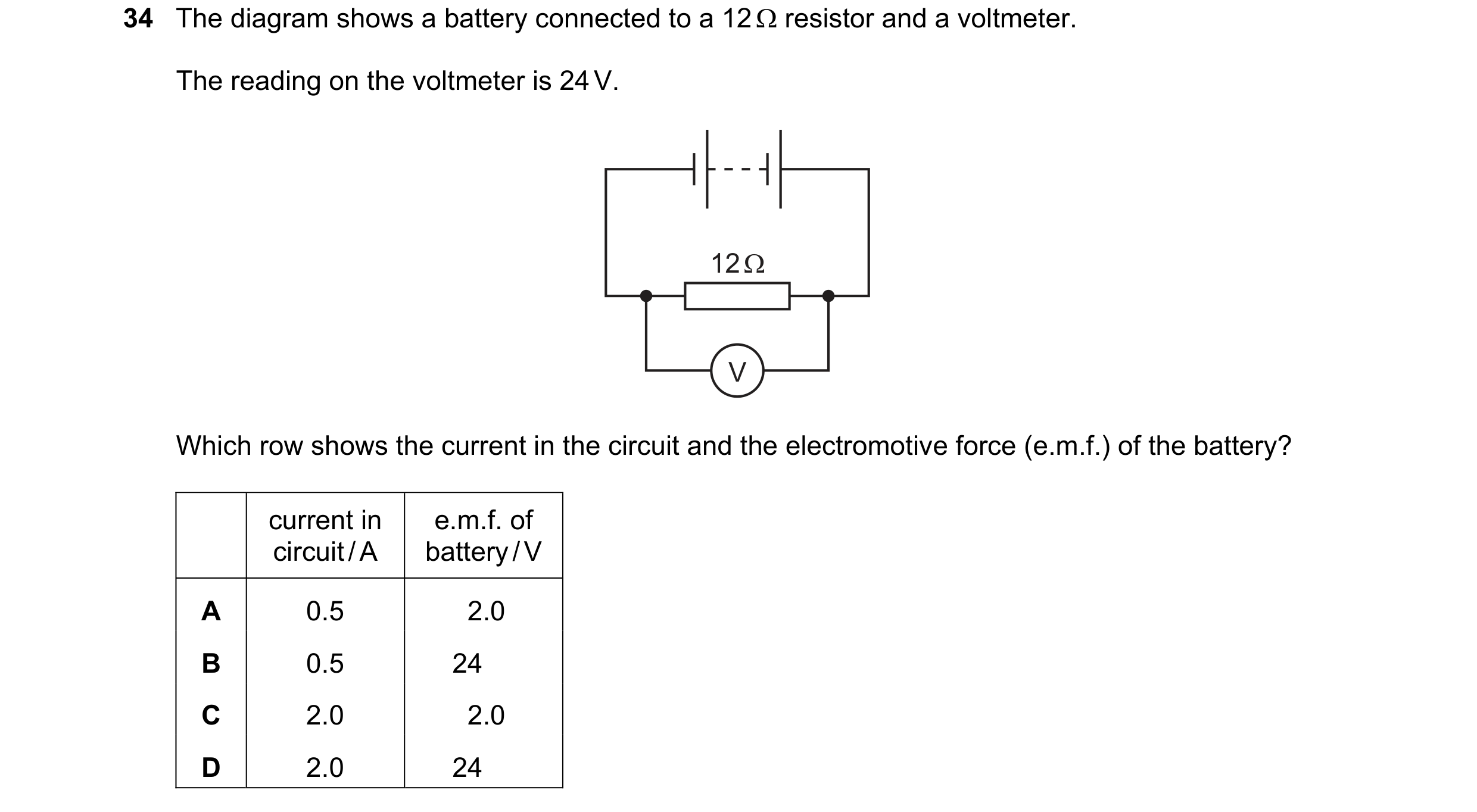
Q40 · The diagram shows a battery connected to a 12 resistor and a voltmeter 0652/11 Oct/Nov 2021
34 The diagram shows a battery connected to a 12 resistor and a voltmeter. The reading on the voltmeter is 24 V. 12 Ω V Which row shows the current in the circuit and the electromotive force (e.m.f.) of the battery? current in e.m.f. of circuit / A battery / V A 0.5 2.0 B 0.5 24 C 2.0 2.0 D 2.0 24
1 marks
Answer: D
This question in 0652/11 Oct/Nov 2021
Q41 · A student connects a lamp, a bell and four switches in the circuit shown 0652/11 Oct/Nov 2021
35 A student connects a lamp, a bell and four switches in the circuit shown. lamp 1 2 bell 3 4 Which switches must be closed for the lamp to light and the bell to ring? A 1, 2, 3 and 4 B 1, 2 and 3 only C 2, 3 and 4 only D 2 and 3 only
1 marks
Answer: B
This question in 0652/11 Oct/Nov 2021
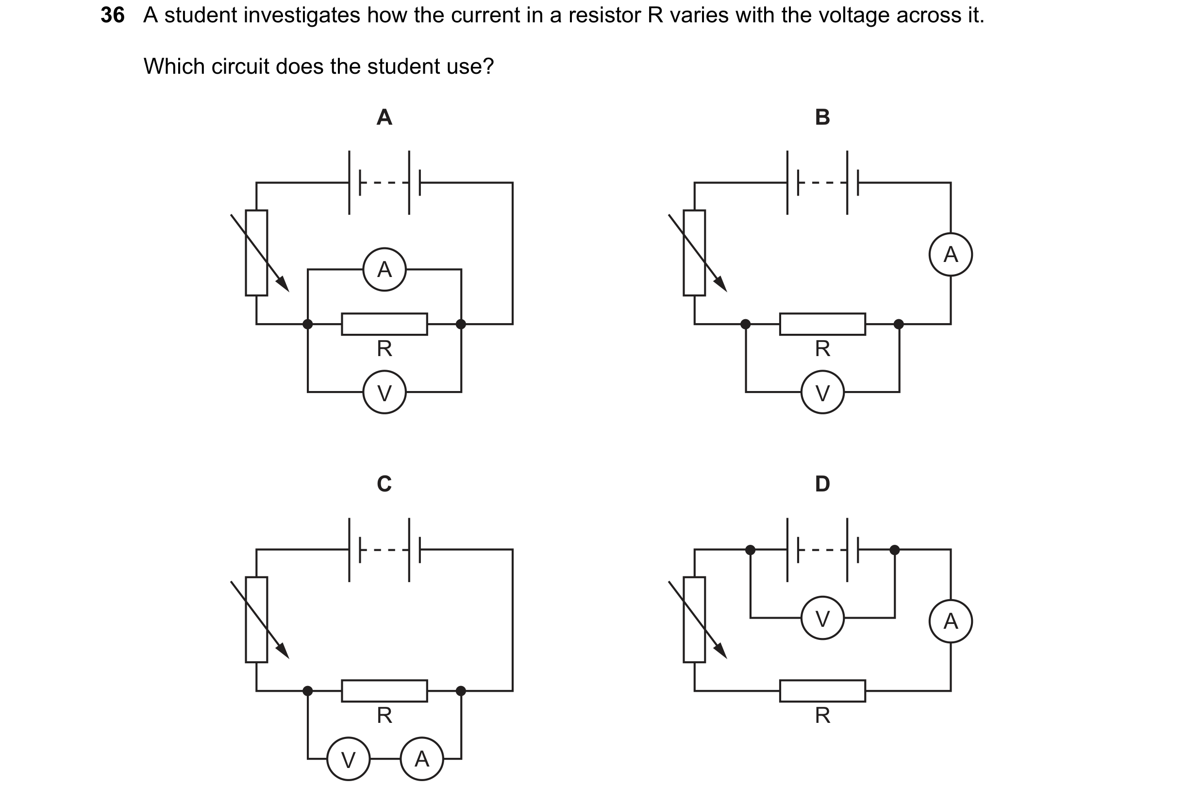
Q42 · A student investigates how the current in a resistor R varies with the voltage across it 0652/11 Oct/Nov 2021
36 A student investigates how the current in a resistor R varies with the voltage across it. Which circuit does the student use? A B A A R R V V C D V A R R V A
1 marks
Answer: B
This question in 0652/11 Oct/Nov 2021
Q43 · The diagrams show the readings on three voltmeters 0652/11 Oct/Nov 2022
35 The diagrams show the readings on three voltmeters. 2 3 2 3 4 6 1 4 1 4 2 8 0 5 0 5 0 10 V V V meter W meter X meter Y Which meters show a reading of 1.6 V? A W only B X only C Y only D W and Y
1 marks
Answer: A
This question in 0652/11 Oct/Nov 2022
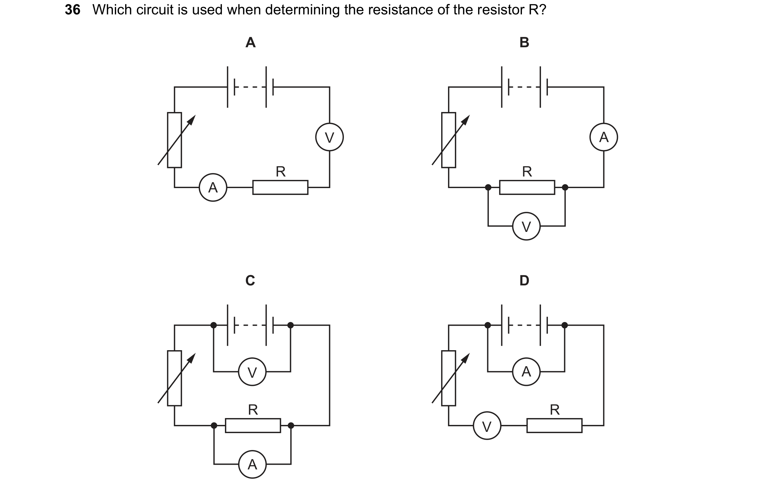
Q44 · Which circuit is used when determining the resistance of the resistor R? 0652/11 Oct/Nov 2022
36 Which circuit is used when determining the resistance of the resistor R? A B V A R R A V C D V A R R V A
1 marks
Answer: B
This question in 0652/11 Oct/Nov 2022
Q45 · What is the benefit of earthing the metal case of an electric kettle? 0652/11 Oct/Nov 2022
37 What is the benefit of earthing the metal case of an electric kettle? A It prevents an electric shock if the live wire touches the metal case. B It prevents the insulation of the cable from becoming damaged. C It prevents overheating of the cable. D It prevents overheating of the kettle.
1 marks
Answer: A
This question in 0652/11 Oct/Nov 2022
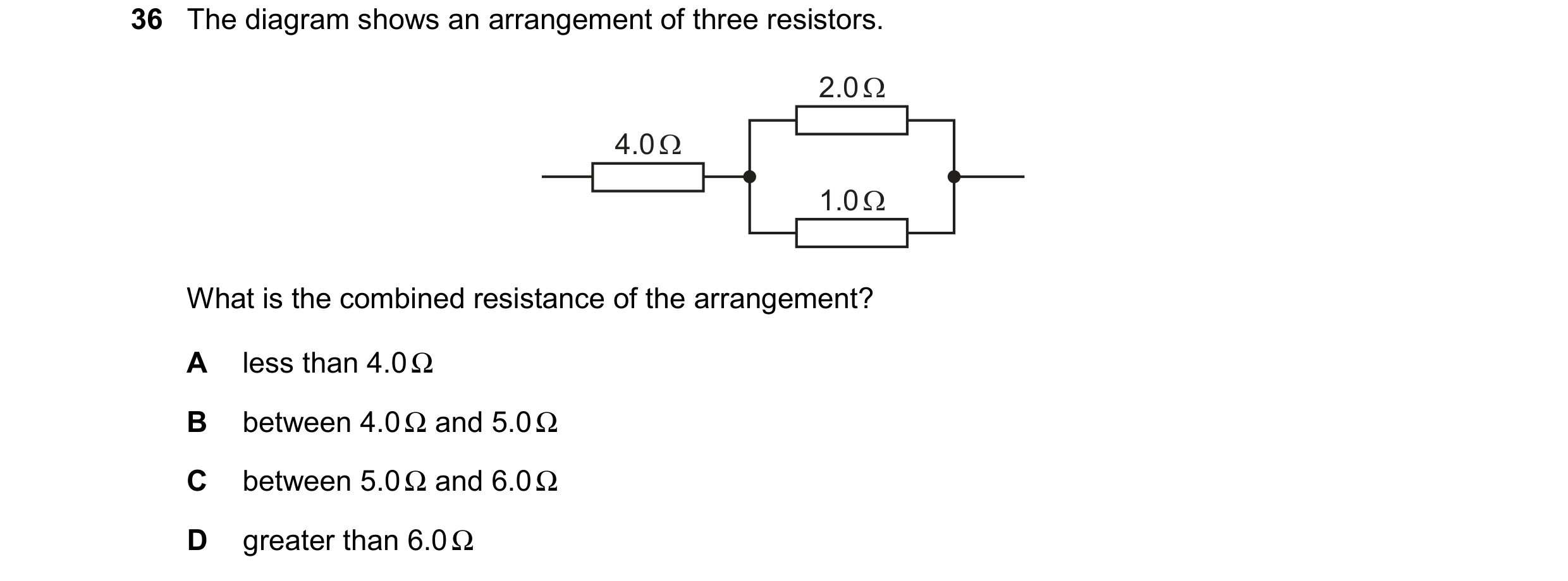
Q46 · The diagram shows an arrangement of three resistors 0652/11 Oct/Nov 2023
36 The diagram shows an arrangement of three resistors.
2.0Q
|
4.00
|
P|
What is the combined resistance of the arrangement?
A less than 4.00
B~ between 4.09 and 5.00
C between 5.0Q and 6.0Q
D
greater than 6.00
1 marks
Answer: B
This question in 0652/11 Oct/Nov 2023
Q47 · A lamp is in a circuit that is protected by a 1 A fuse 0652/11 Oct/Nov 2023
37 A lamp is in a circuit that is protected by a 1 A fuse. The lamp is switched on and it lights normally. The 1 A fuse is now replaced with a 5 A fuse. What happens when the lamp is switched on? A The lamp lights normally. B The fuse blows so the lamp does not light. C The lamp lights less brightly. D The lamp lights more brightly.
1 marks
Answer: A
This question in 0652/11 Oct/Nov 2023
Q48 · The diagram shows an arrangement of three resistors 0652/12 Oct/Nov 2023
36 The diagram shows an arrangement of three resistors.
2.00
|
4.00
|
|
What is the combined resistance of the arrangement?
A _siless than 4.0Q
B_ between 4.0Q and 5.00
C between 5.0Q and 6.02
D
greater than 6.09
1 marks
Answer: B
This question in 0652/12 Oct/Nov 2023
Q49 · A lamp is in a circuit that is protected by a 1 A fuse 0652/12 Oct/Nov 2023
37 A lamp is in a circuit that is protected by a 1 A fuse. The lamp is switched on and it lights normally. The 1 A fuse is now replaced with a 5 A fuse. What happens when the lamp is switched on? A The lamp lights normally. B The fuse blows so the lamp does not light. C The lamp lights less brightly. D The lamp lights more brightly.
1 marks
Answer: A
This question in 0652/12 Oct/Nov 2023
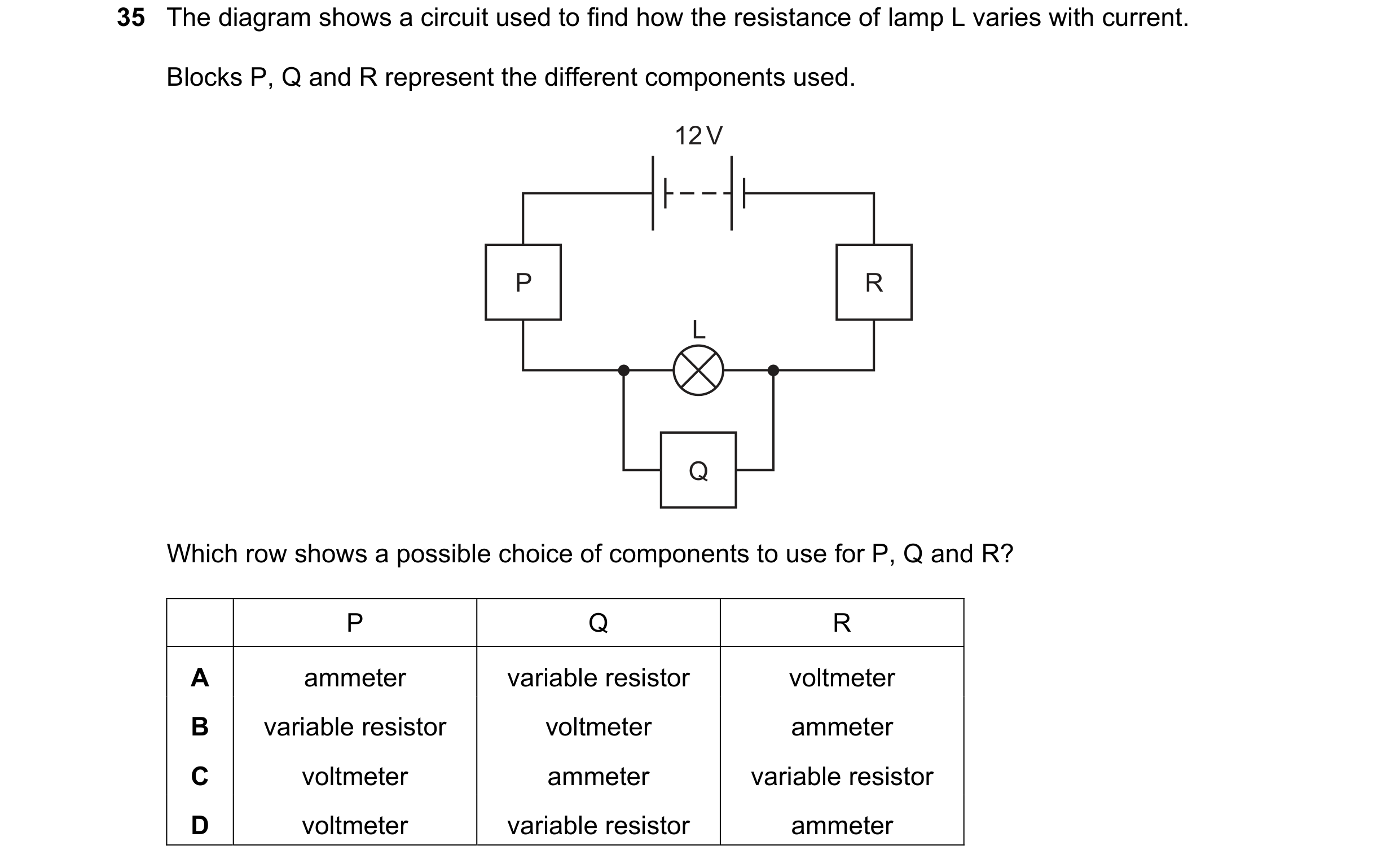
Q50 · The diagram shows a circuit used to find how the resistance of lamp L varies with current 0652/11 Oct/Nov 2024
35 The diagram shows a circuit used to find how the resistance of lamp L varies with current. Blocks P, Q and R represent the different components used. 12 V P R L Q Which row shows a possible choice of components to use for P, Q and R? P Q R A ammeter variable resistor voltmeter B variable resistor voltmeter ammeter C voltmeter ammeter variable resistor D voltmeter variable resistor ammeter
1 marks
Answer: B
This question in 0652/11 Oct/Nov 2024
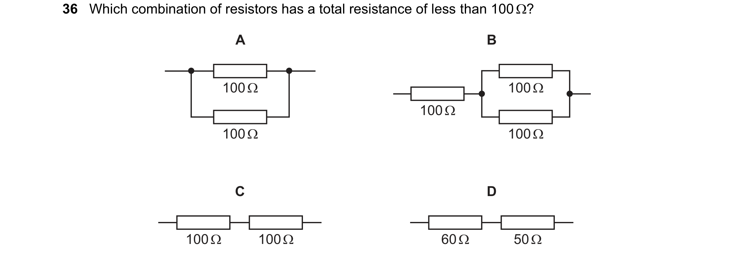
Q51 · Which combination of resistors has a total resistance of less than 100 Q? 0652/11 Oct/Nov 2024
36 Which combination of resistors has a total resistance of less than 100 Q?
A B
a
|
1002
Cc D
—L___ | -L___} — —L___}|-L___} —
1009 1000 602 502
1 marks
Answer: A
This question in 0652/11 Oct/Nov 2024
 1 / 20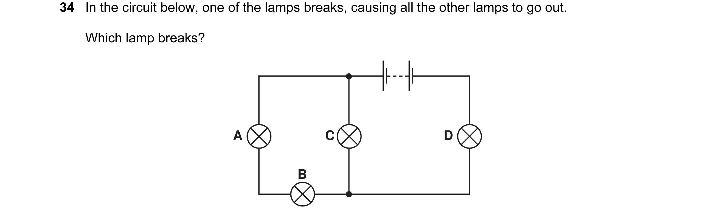
 2 / 20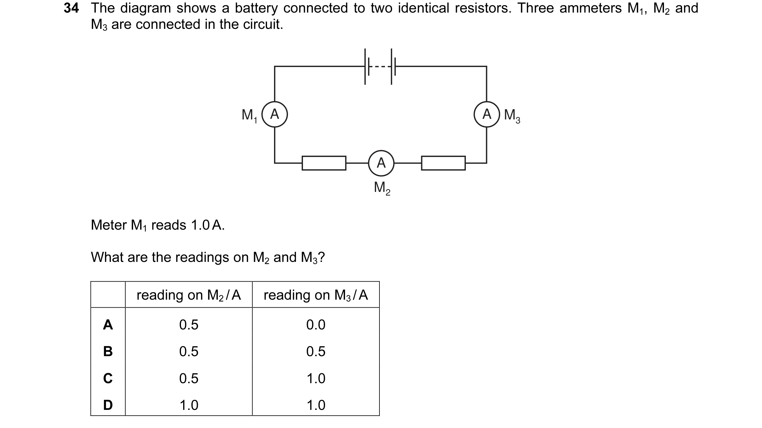
 3 / 20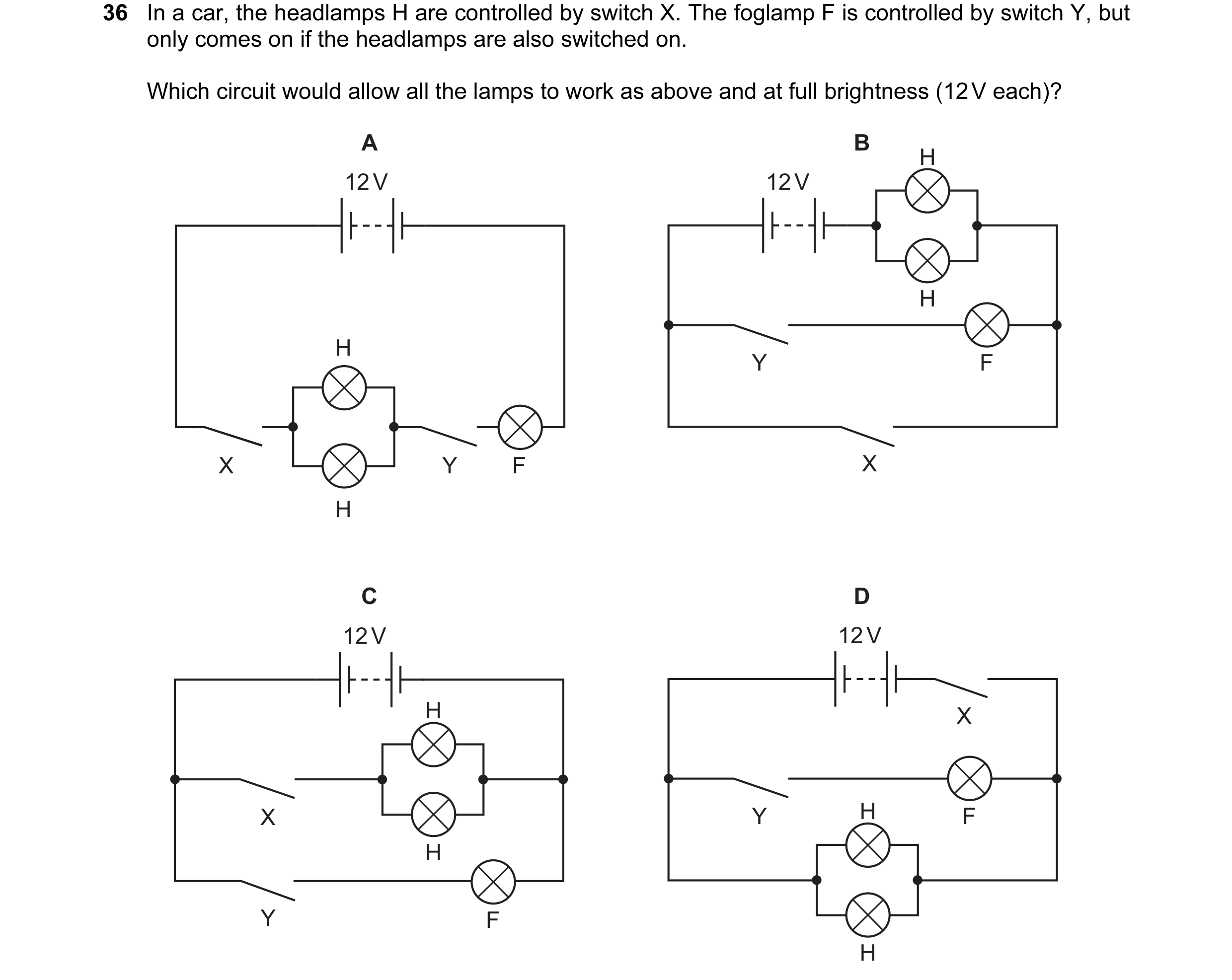
 4 / 20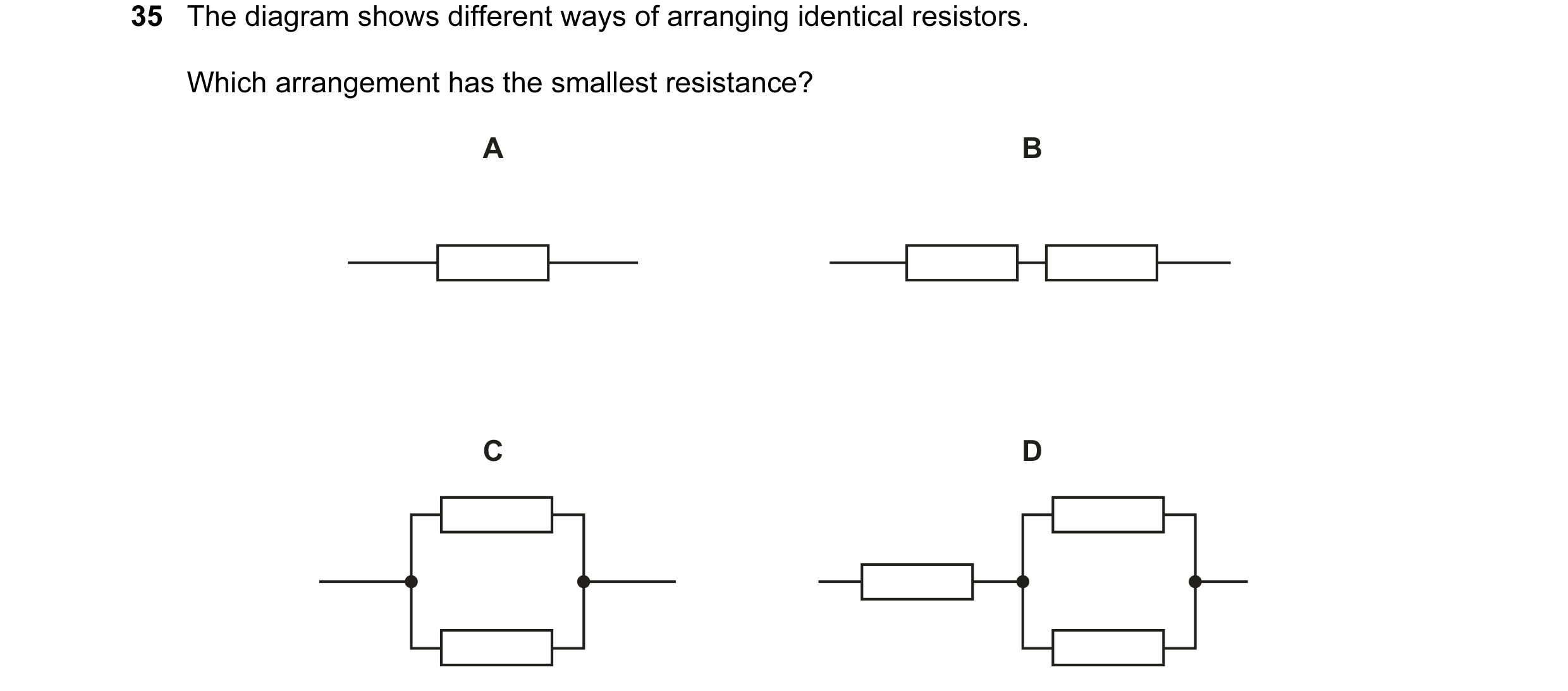
 5 / 20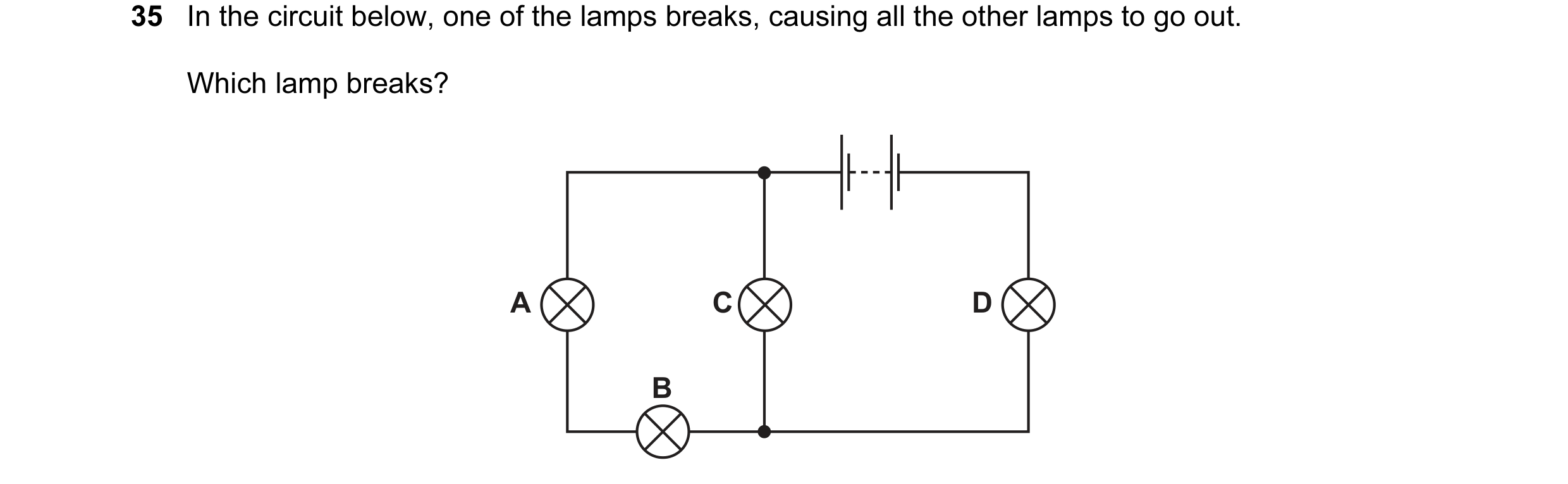
 6 / 20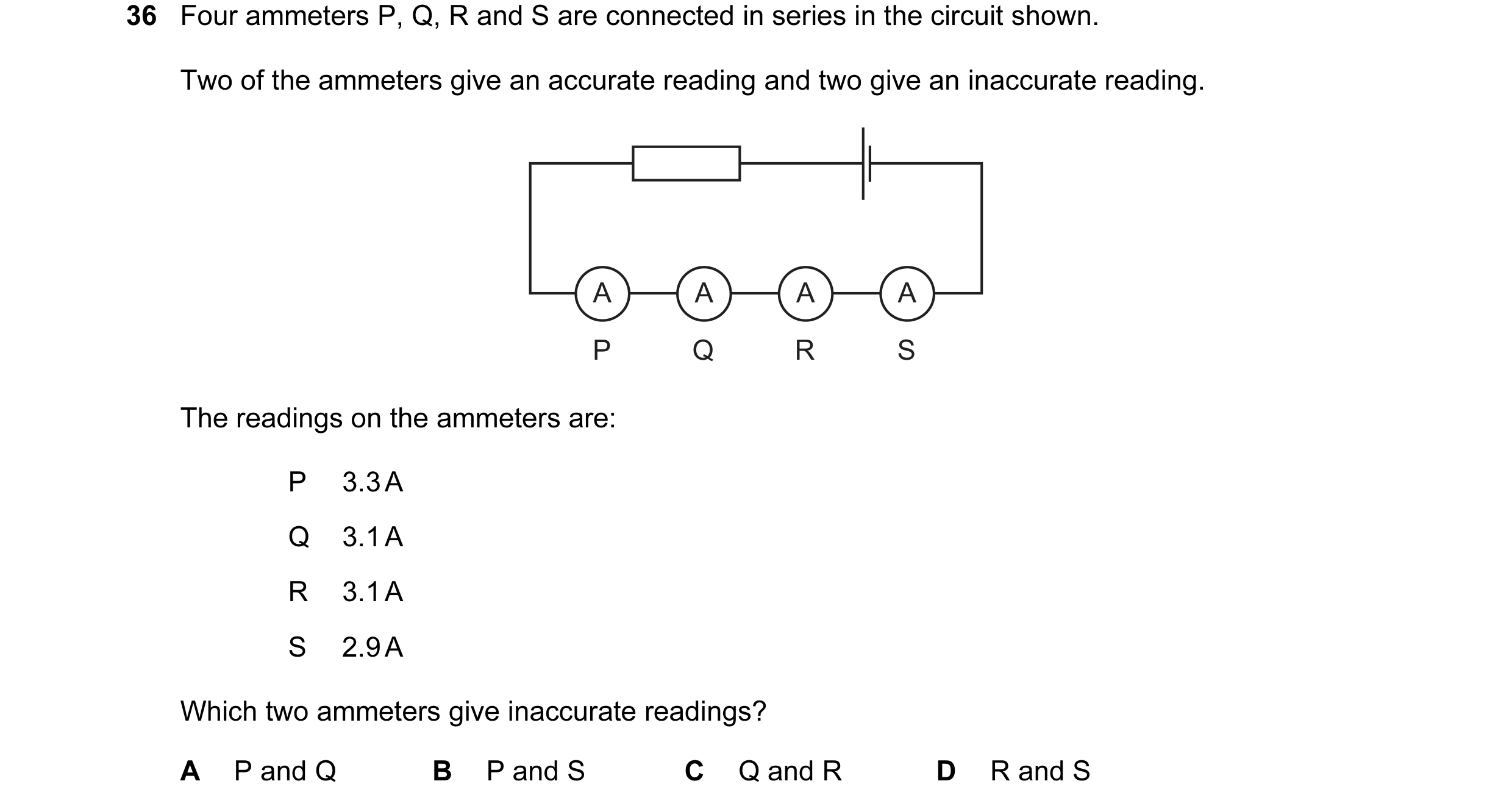
 7 / 20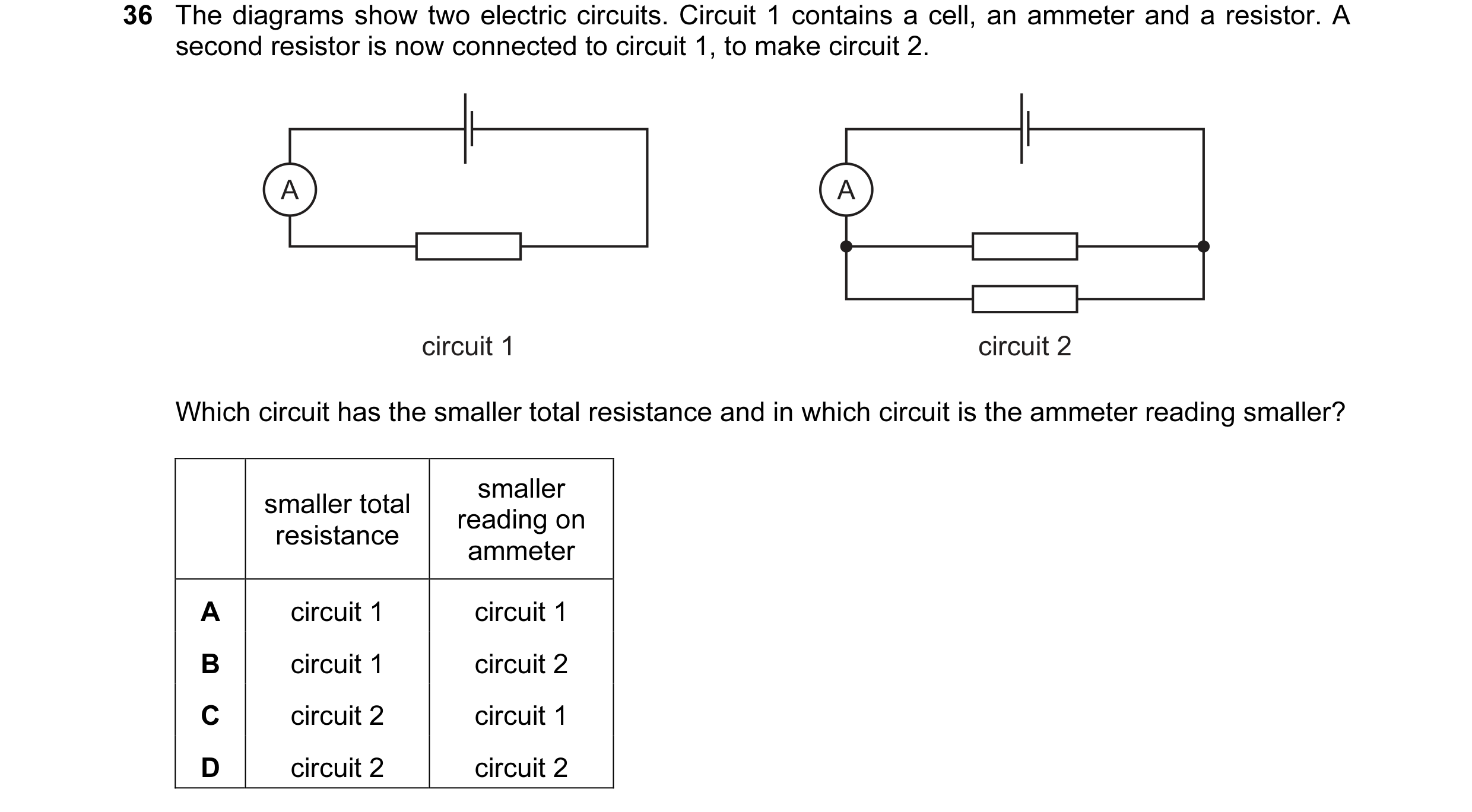
 8 / 20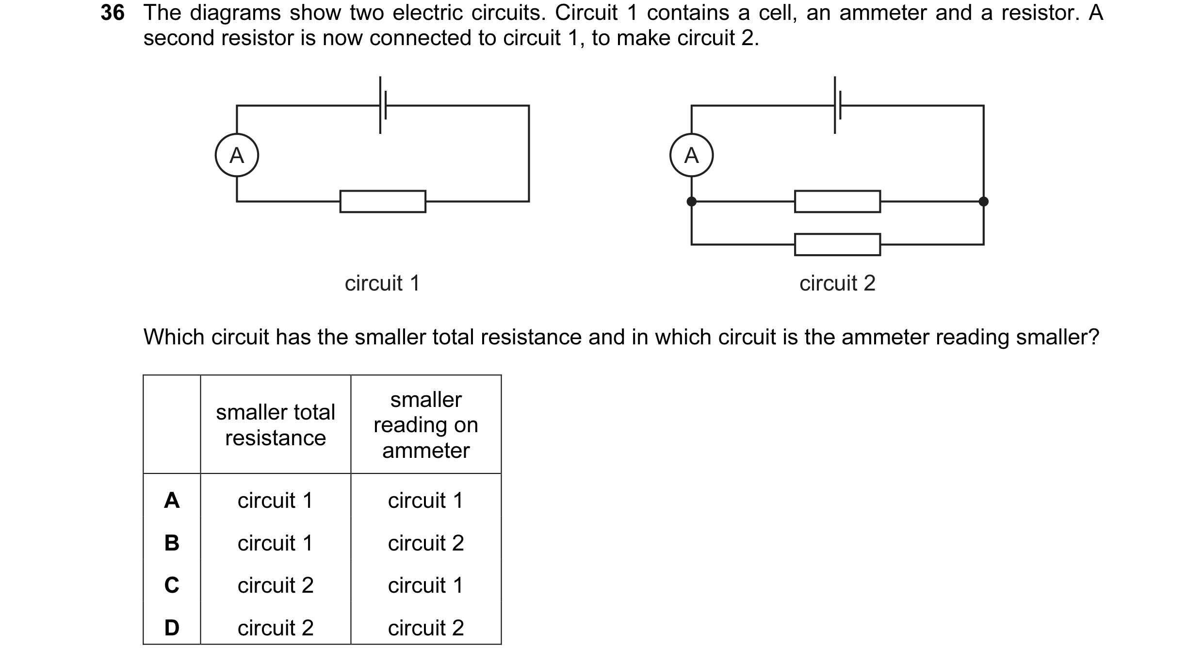
 9 / 20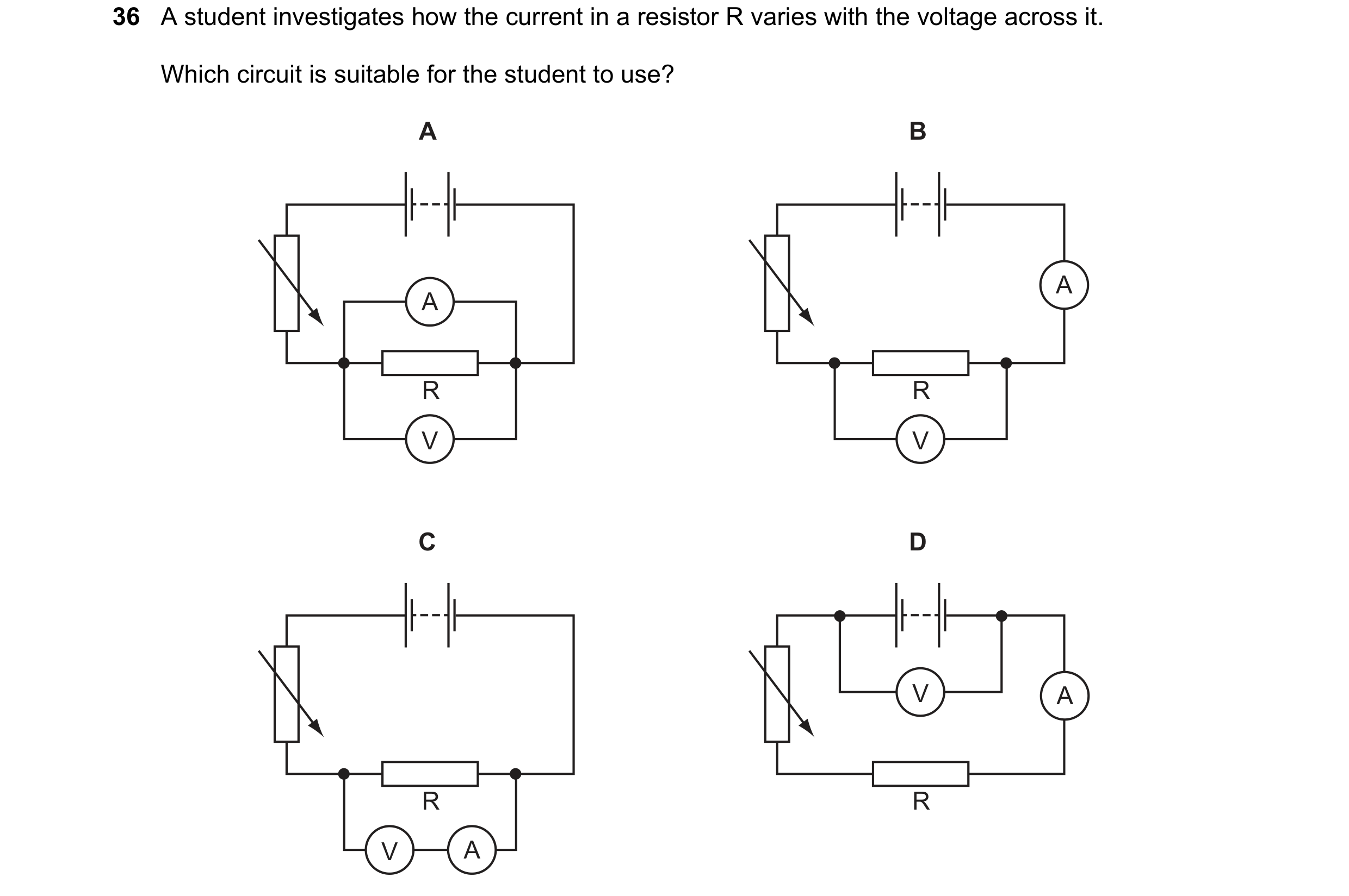
 10 / 20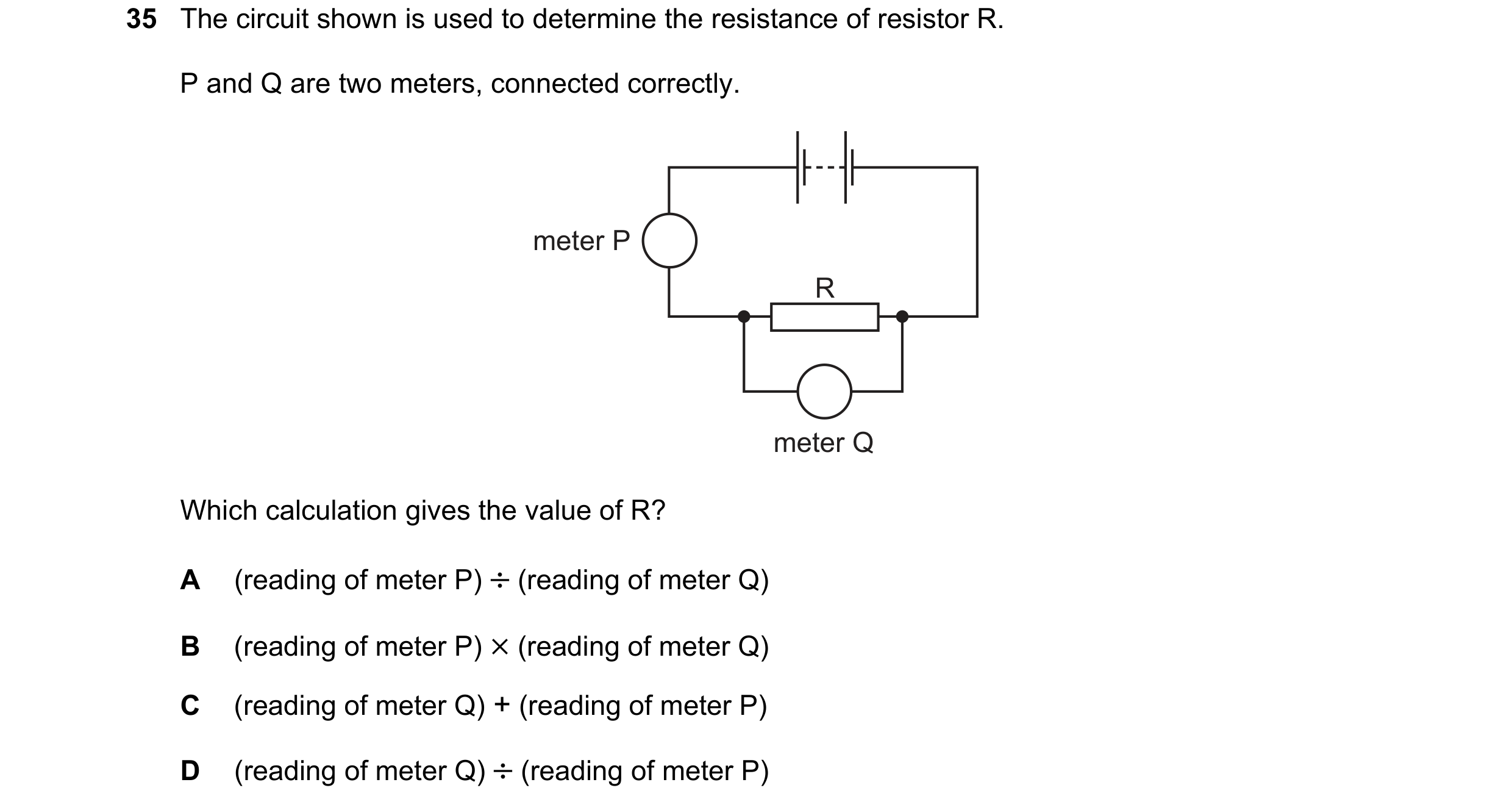
 11 / 20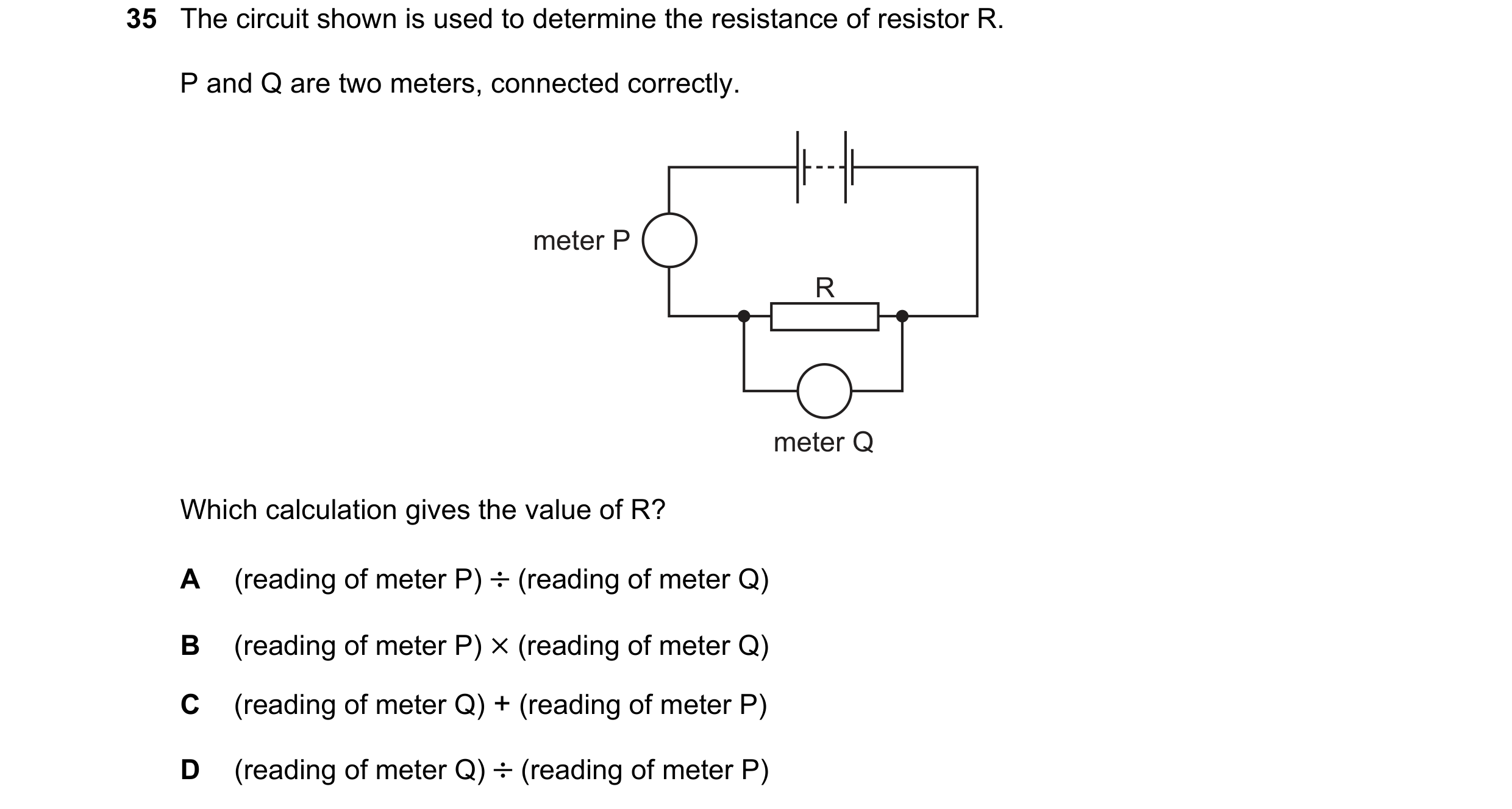
 12 / 20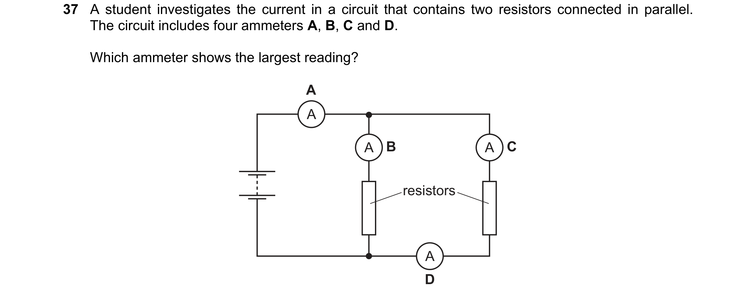
 13 / 20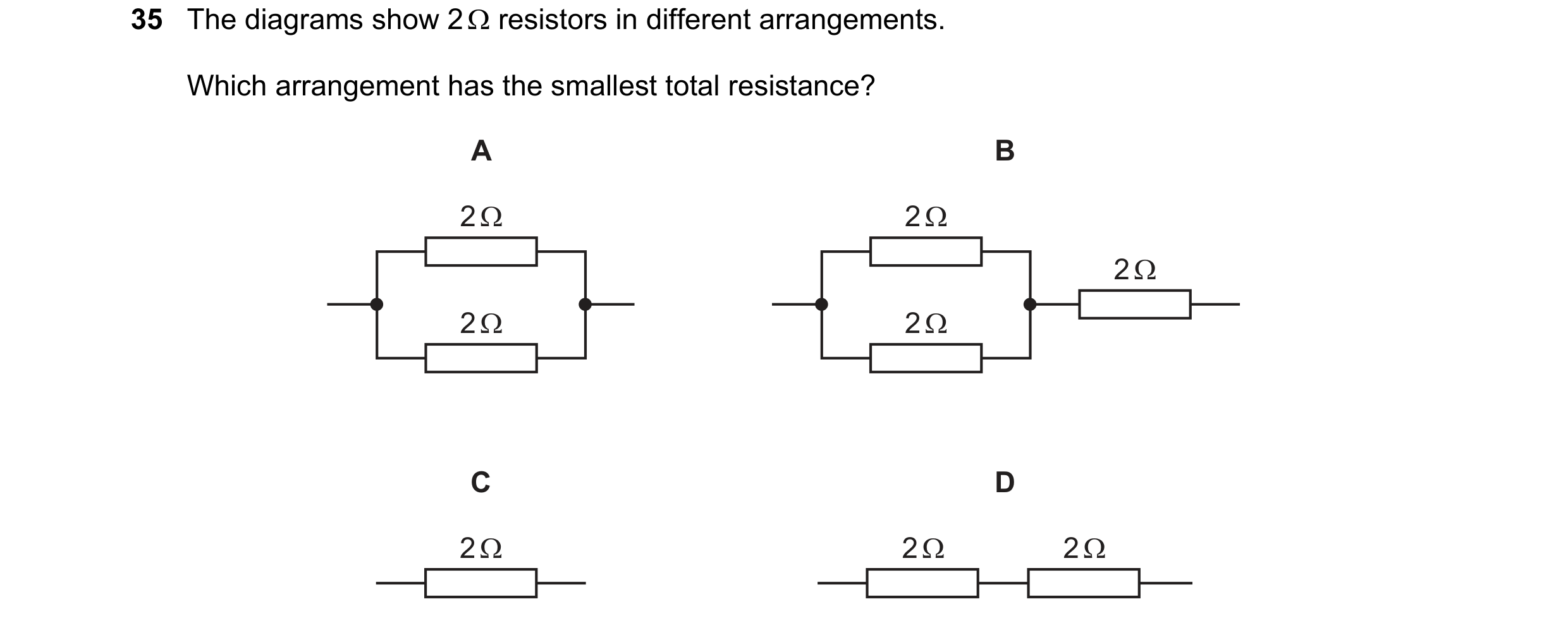

 14 / 20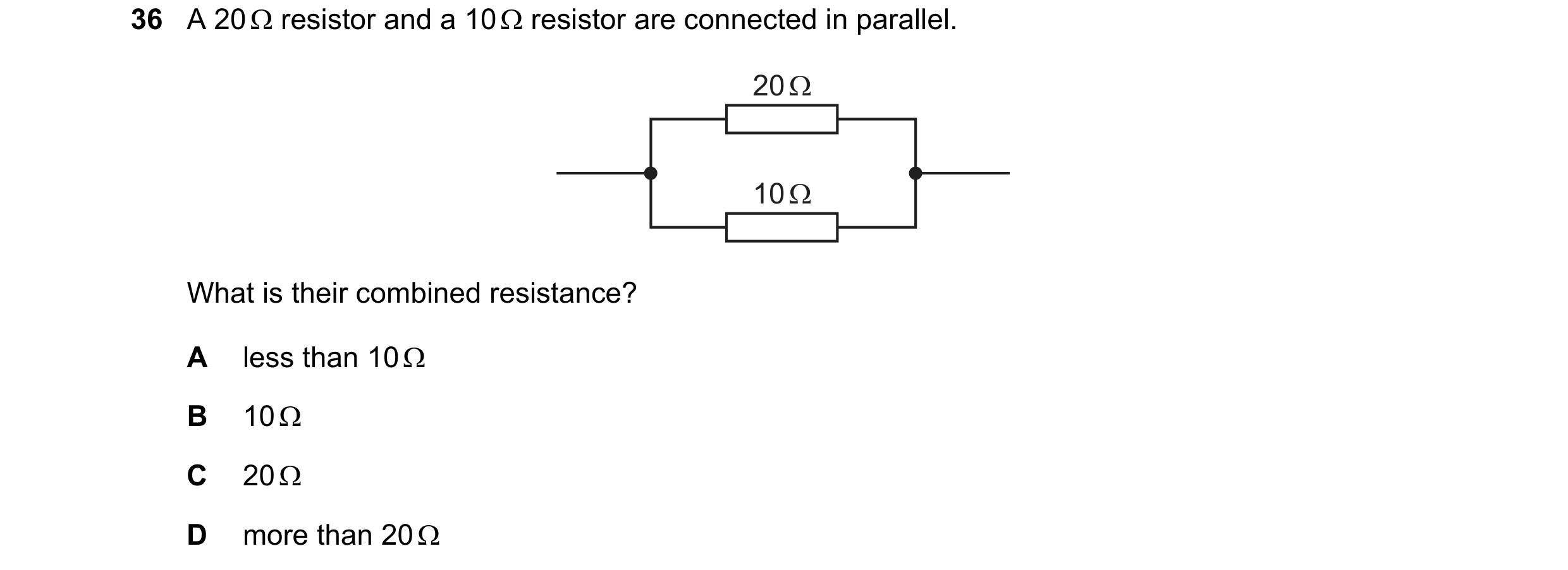
 15 / 20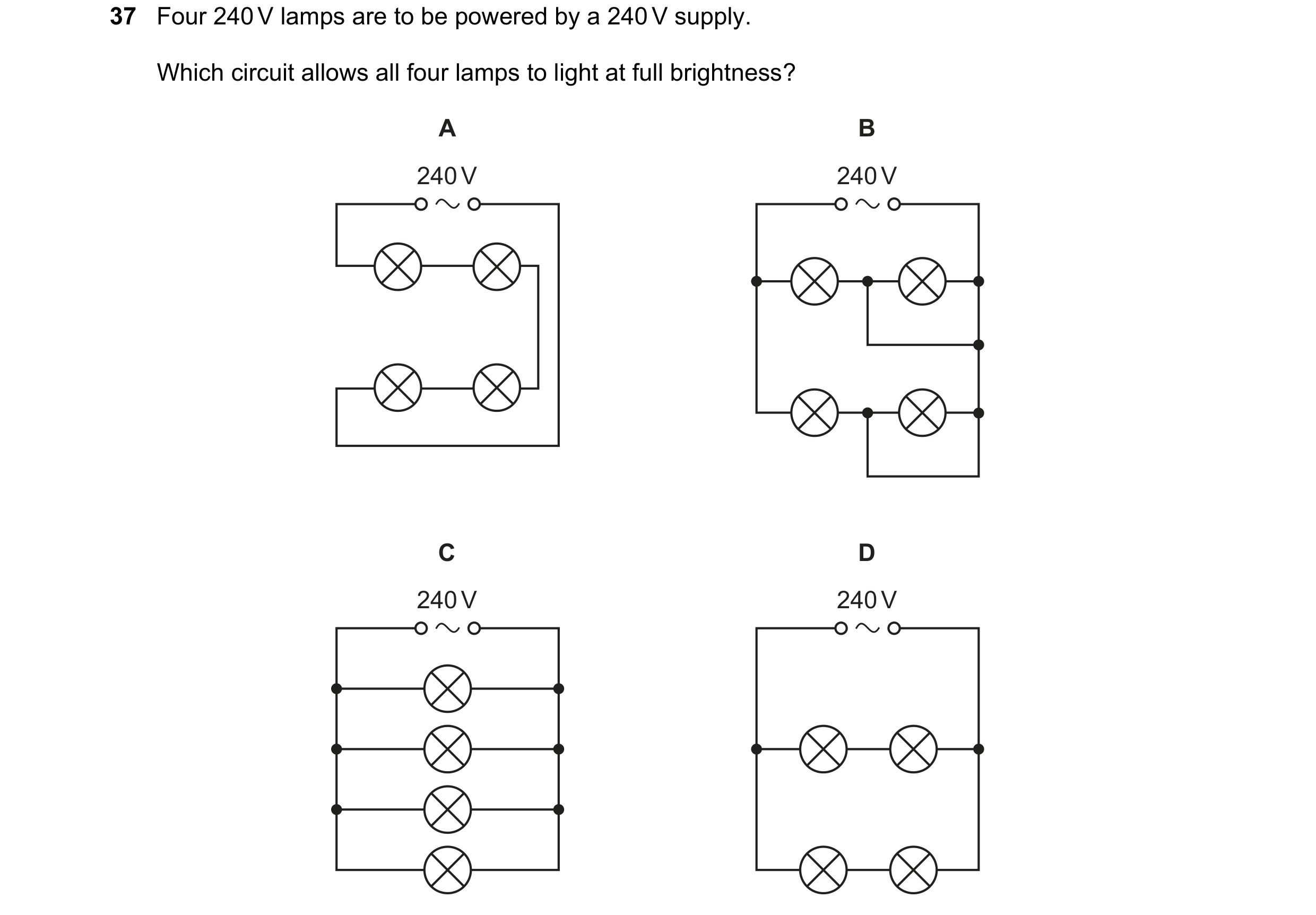
 16 / 20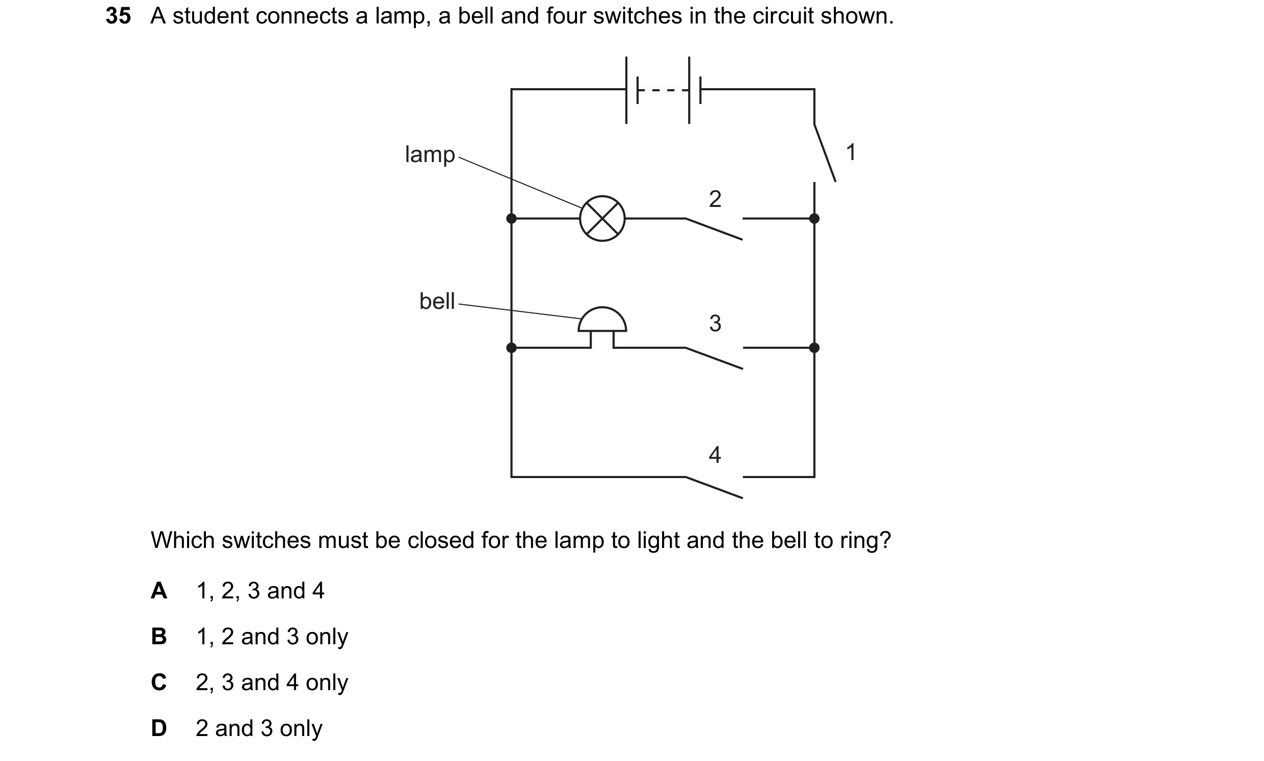
 17 / 20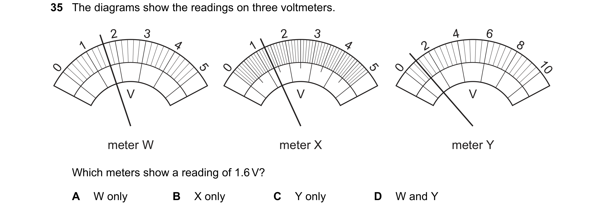
 18 / 20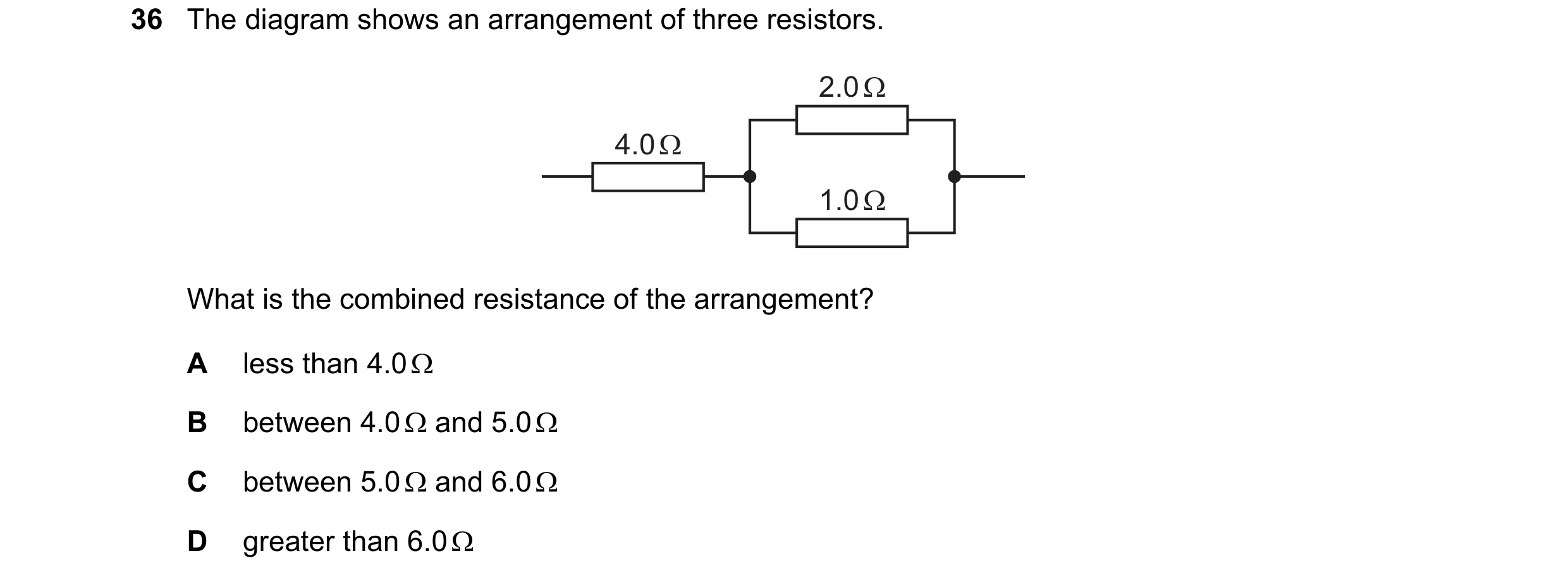
 19 / 20
 20 / 20