Questions as text
Question 1 9702/21 May/June 2018
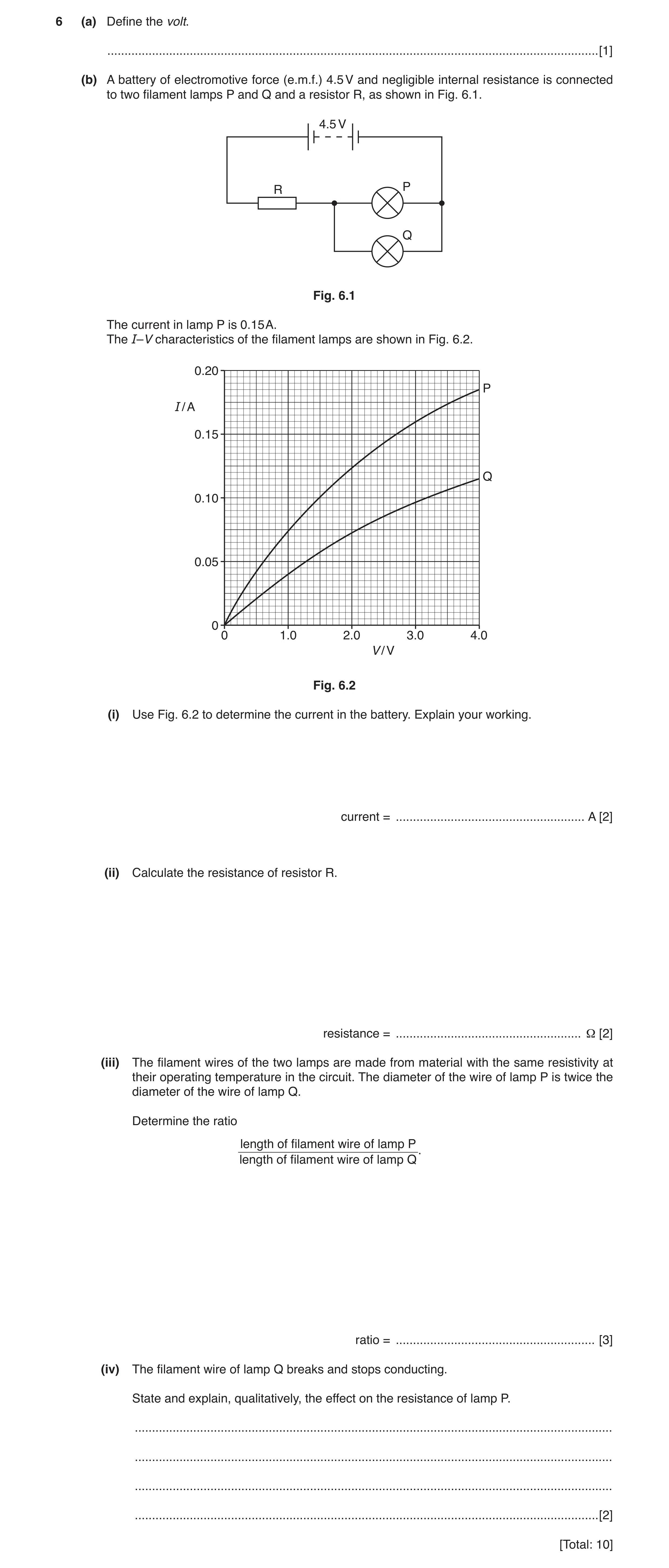
6 (a) Define the volt. … [1] (b) A battery of electromotive force (e.m.f.) 4.5 V and negligible internal resistance is connected to two filament lamps P and Q and a resistor R, as shown in Fig. 6.1. 4.5 V R P Q Fig. 6.1 The current in lamp P is 0.15 A. The I–V characteristics of the filament lamps are shown in Fig. 6.2. 0.20 P I / A 0.15 Q 0.10 0.05 0 0 1.0 2.0 3.0 4.0 V / V Fig. 6.2 (i) Use Fig. 6.2 to determine the current in the battery. Explain your working. current = … A [2] (ii) Calculate the resistance of resistor R. resistance = … Ω [2] (iii) The filament wires of the two lamps are made from material with the same resistivity at their operating temperature in the circuit. The diameter of the wire of lamp P is twice the diameter of the wire of lamp Q. Determine the ratio length of filament wire of lamp P length of filament wire of lamp Q. ratio = … [3] (iv) The filament wire of lamp Q breaks and stops conducting. State and explain, qualitatively, the effect on the resistance of lamp P. … … … … [2] [Total: 10]
10 marks
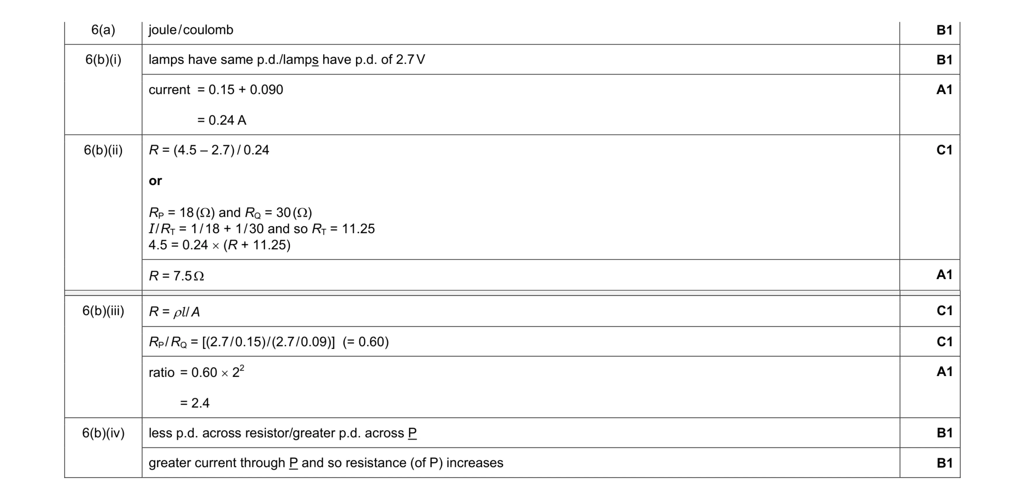
Mark scheme: 6(a) joule / coulomb B1 6(b)(i) lamps have same p.d./lamps have p.d. of 2.7 V B1 current = 0.15 + 0.090 = 0.24 A A1 6(b)(ii) R = (4.5 – 2.7) / 0.24 or RP = 18 (Ω) and RQ = 30 (Ω) I / RT = 1 / 18 + 1 / 30 and so RT = 11.25 4.5 = 0.24 × (R + 11.25) C1 R = 7.5 Ω A1 Question Answer Marks 6(b)(iii) R = ρl / A C1 RP / RQ = [(2.7 / 0.15) / (2.7 / 0.09)] (= 0.60) C1 ratio = 0.60 × 22 = 2.4 A1 6(b)(iv) less p.d. across resistor/greater p.d. across P B1 greater current through P and so resistance (of P) increases B1
This question in 9702/21 May/June 2018
Q2 · A solid cylinder is lifted out of oil by a wire attached to a motor 9702/22 May/June 2018
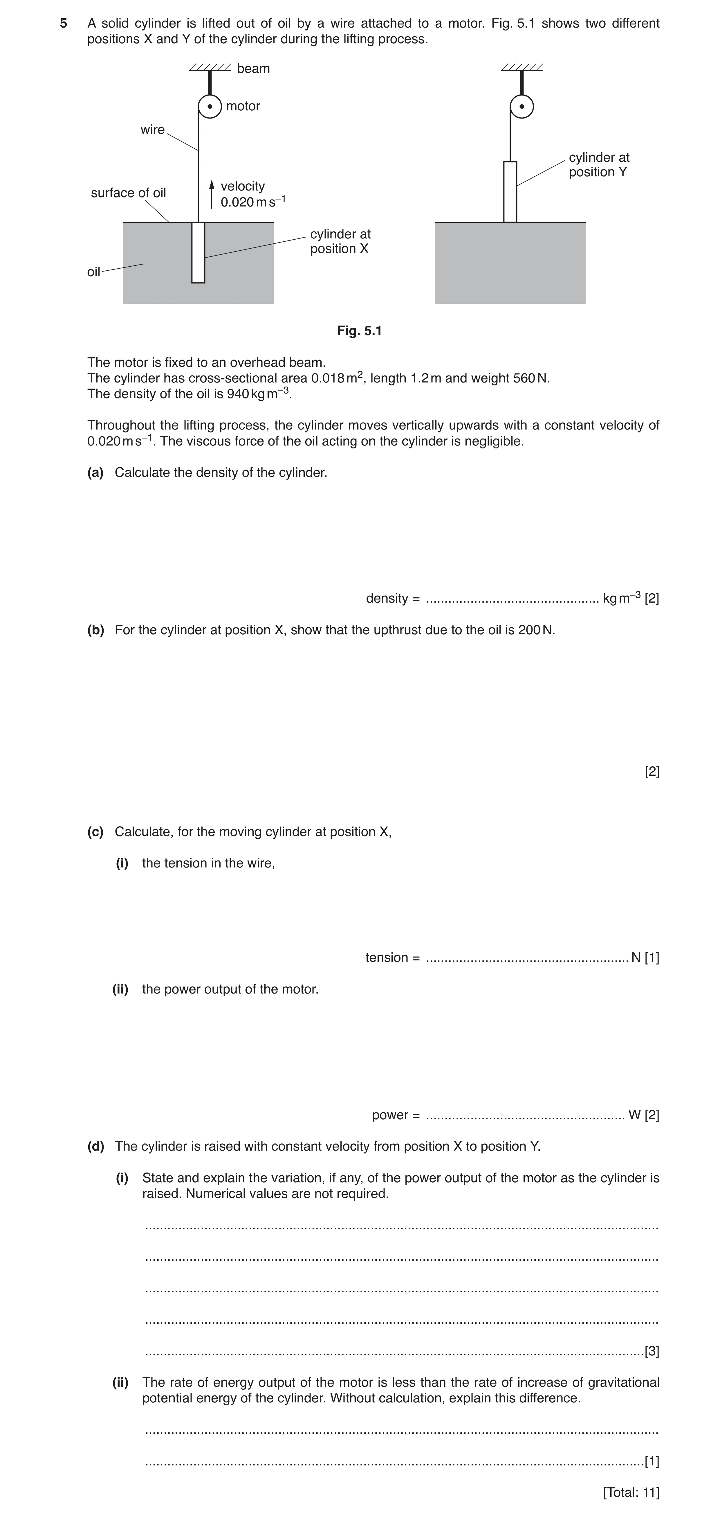
5 A solid cylinder is lifted out of oil by a wire attached to a motor. Fig. 5.1 shows two different positions X and Y of the cylinder during the lifting process. beam motor wire cylinder at position Y velocity surface of oil 0.020 m s–1 cylinder at position X oil Fig. 5.1 The motor is fixed to an overhead beam. The cylinder has cross-sectional area 0.018 m2, length 1.2 m and weight 560 N. The density of the oil is 940 kg m–3. Throughout the lifting process, the cylinder moves vertically upwards with a constant velocity of 0.020 m s–1. The viscous force of the oil acting on the cylinder is negligible. (a) Calculate the density of the cylinder. density = … kg m–3 [2] (b) For the cylinder at position X, show that the upthrust due to the oil is 200 N. [2] (c) Calculate, for the moving cylinder at position X, (i) the tension in the wire, tension = … N [1] (ii) the power output of the motor. power = … W [2] (d) The cylinder is raised with constant velocity from position X to position Y. (i) State and explain the variation, if any, of the power output of the motor as the cylinder is raised. Numerical values are not required. … … … … … [3] (ii) The rate of energy output of the motor is less than the rate of increase of gravitational potential energy of the cylinder. Without calculation, explain this difference. … … [1] [Total: 11]
11 marks
Mark scheme: 5(a) C1 = (560 / 9.81) / (1.2 × 0.018) = 2600 kg m–3 A1 5(b) (∆)p = 940 × 9.81 × 1.2 C1 (upthrust =) 940 × 9.81 × 1.2 × 0.018 = 200 N A1 5(c)(i) tension = 560 – 200 = 360 N A1 5(c)(ii) P = Fv C1 = 360 × 0.020 = 7.2 W A1 5(d)(i) upthrust decreases B1 tension (in wire) increases M1 power (output of motor) increases A1 5(d)(ii) there is work done (on the cylinder) by the upthrust or GPE of oil decreases (as it fills the space left by cylinder and so total energy is conserved) B1
This question in 9702/22 May/June 2018
Q3 · An analogue voltmeter is used to take measurements of a constant potential difference… 9702/23 May/June 2018
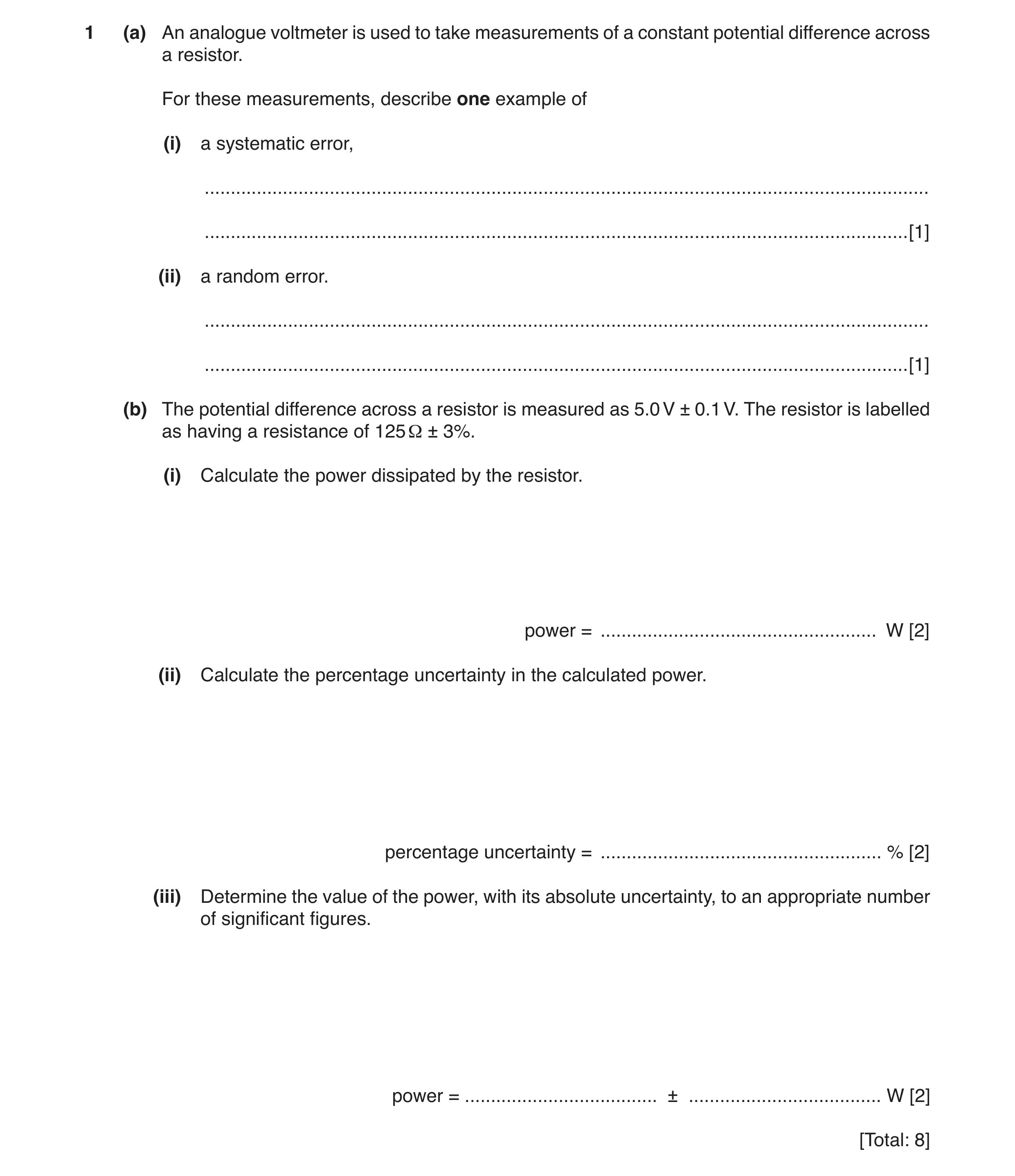
1 (a) An analogue voltmeter is used to take measurements of a constant potential difference across a resistor. For these measurements, describe one example of (i) a systematic error, … … [1] (ii) a random error. … … [1] (b) The potential difference across a resistor is measured as 5.0 V ± 0.1 V. The resistor is labelled as having a resistance of 125 Ω ± 3%. (i) Calculate the power dissipated by the resistor. power = … W [2] (ii) Calculate the percentage uncertainty in the calculated power. percentage uncertainty = … % [2] (iii) Determine the value of the power, with its absolute uncertainty, to an appropriate number of significant figures. power = … ± … W [2] [Total: 8]
8 marks
Mark scheme: 1(a)(i) zero error or wrongly calibrated scale B1 1(a)(ii) reading scale from different angles or wrongly interpolating between scale readings/divisions B1 1(b)(i) P = V 2 / R or P = VI and V = IR C1 P = 5.02 / 125 or 5.0 × 0.04 or (0.04)2 × 125 = 0.20 W A1 1(b)(ii) %V = 2% or ∆V / V = 0.02 C1 %P = (2 × 2%) + 3% or %P = (2 × 0.02 + 0.03) × 100 = 7% A1 1(b)(iii) absolute uncertainty in P = (7 / 100) × 0.20 = 0.014 C1 power = 0.20 ± 0.01 W or (2.0 ± 0.1) × 10–1 W A1
This question in 9702/23 May/June 2018
Question 4 9702/21 Oct/Nov 2018
3 (a) (i) Define power. … … [1] (ii) State what is meant by gravitational potential energy. … … [1] (b) An aircraft of mass 1200 kg climbs upwards with a constant velocity of 45 m s–1, as shown in Fig. 3.1. velocity thrust force 45 m s–1 2.0 × 10³ N path of aircraft aircraft mass 1200 kg Fig. 3.1 (not to scale) The aircraft’s engine produces a thrust force of 2.0 × 10³ N to move the aircraft through the air. The rate of increase in height of the aircraft is 3.3 m s–1. (i) Calculate the power produced by the thrust force. power = … W [2] (ii) Determine, for a time interval of 3.0 minutes, 1. the work done by the thrust force to move the aircraft, work done = … J [2] 2. the increase in gravitational potential energy of the aircraft, increase in gravitational potential energy = … J [2] 3. the work done against air resistance. work done = … J [1] (iii) Use your answer in (b)(ii) part 3 to calculate the force due to air resistance acting on the aircraft. force = … N [1] (iv) With reference to the motion of the aircraft, state and explain whether the aircraft is in equilibrium. … … … [2] [Total: 12]
12 marks
Mark scheme: 3(a)(i) work (done) / time (taken) B1 3(a)(ii) energy of a mass due to its position in a gravitational field B1 3(b)(i) P = Fv C1 = 2.0 × 103 × 45 = 9.0 × 10⁴ W A1 3(b)(ii) 1. W = (2.0 × 103) × (45 × 3.0 × 60) or W = 9.0 × 104 × 3.0 × 60 C1 W = 1.6 × 10⁷ J A1 2. (∆)EP = mg(∆)h C1 = 1200 × 9.81 × 3.3 × 3.0 × 60 = 7.0 × 10⁶ J A1 3. W = 1.6 × 10⁷ – 7.0 × 106 = 9.0 × 10⁶ J A1 3(b)(iii) force = (9.0 × 10⁶) / (45 × 3.0 × 60) = 1.1 × 10³ N A1 3(b)(iv) constant velocity so no resultant force B1 no resultant force so in equilibrium B1
This question in 9702/21 Oct/Nov 2018
Question 5 9702/22 Oct/Nov 2018
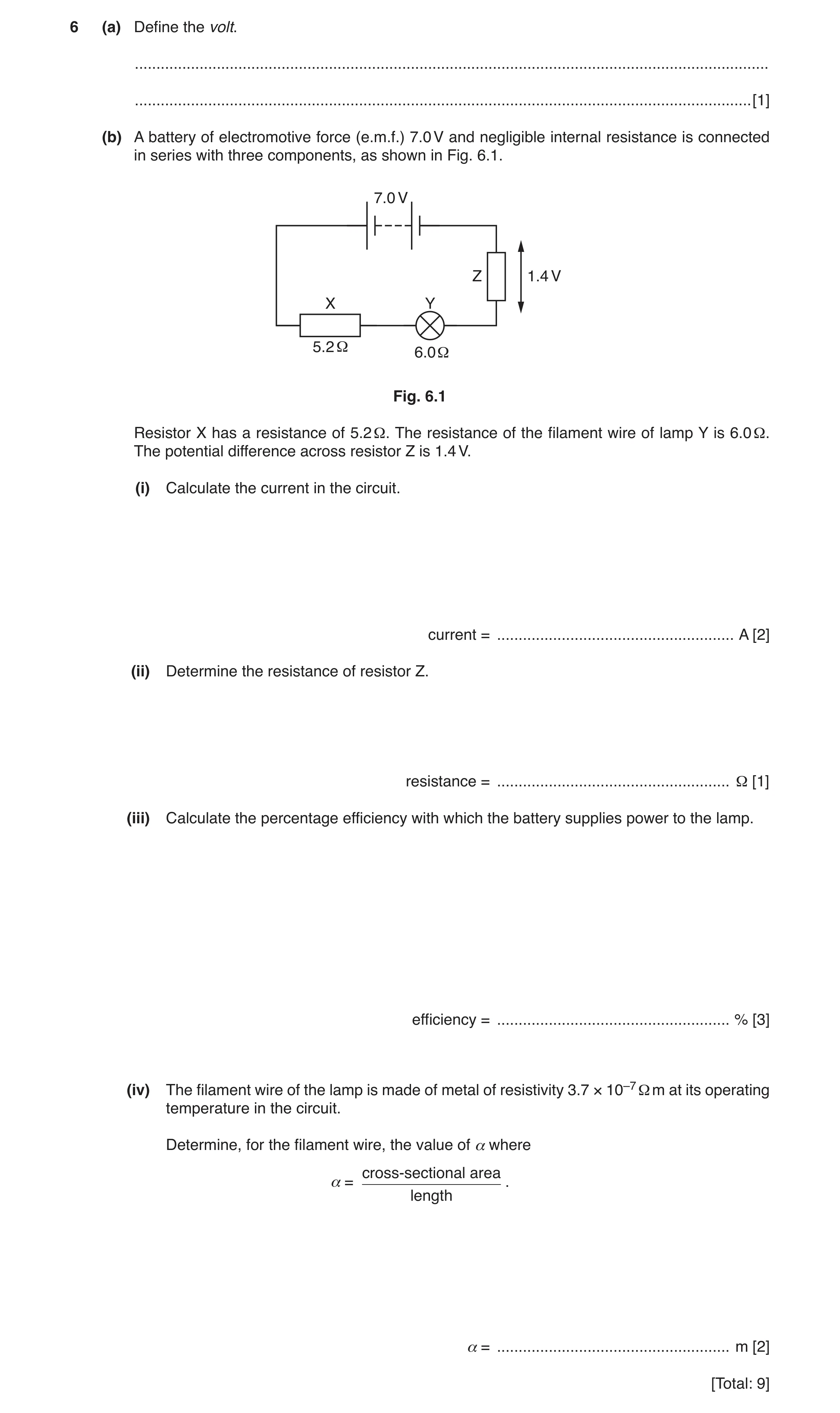
6 (a) Define the volt. … … [1] (b) A battery of electromotive force (e.m.f.) 7.0 V and negligible internal resistance is connected in series with three components, as shown in Fig. 6.1. 7.0 V Z 1.4 V X Y 5.2 Ω 6.0 Ω Fig. 6.1 Resistor X has a resistance of 5.2 Ω. The resistance of the filament wire of lamp Y is 6.0 Ω. The potential difference across resistor Z is 1.4 V. (i) Calculate the current in the circuit. current = … A [2] (ii) Determine the resistance of resistor Z. resistance = … Ω [1] (iii) Calculate the percentage efficiency with which the battery supplies power to the lamp. efficiency = … % [3] (iv) The filament wire of the lamp is made of metal of resistivity 3.7 × 10⁻⁷ Ω m at its operating temperature in the circuit. Determine, for the filament wire, the value of α where cross-sectional area α = . length α = … m [2] [Total: 9]
9 marks
Mark scheme: 6(a) joule / coulomb B1 6(b)(i) 7.0 = (I × 5.2) + (I × 6.0) + 1.4 C1 I = 0.50 A A1 6(b)(ii) R = 1.4 / 0.50 = 2.8 Ω A1 6(b)(iii) P = EI or P = VI or P = I2R or P = V2 / R C1 efficiency = [(0.502 × 6.0) / (7.0 × 0.50)] (×100) or efficiency = [(0.50 × 3.0) / (7.0 × 0.50)] (×100) or efficiency = [(3.02 / 6.0) / (7.0 × 0.50)] (×100) C1 efficiency = 43% A1 6(b)(iv) R = ρl / A C1 α = ρ / R = 3.7 × 10⁻⁷ / 6.0 = 6.2 × 10⁻⁸ m A1
This question in 9702/22 Oct/Nov 2018
Q6 · Using energy transformations, describe the electromotive force (e.m.f.) of a battery and… 9702/22 Feb/March 2019
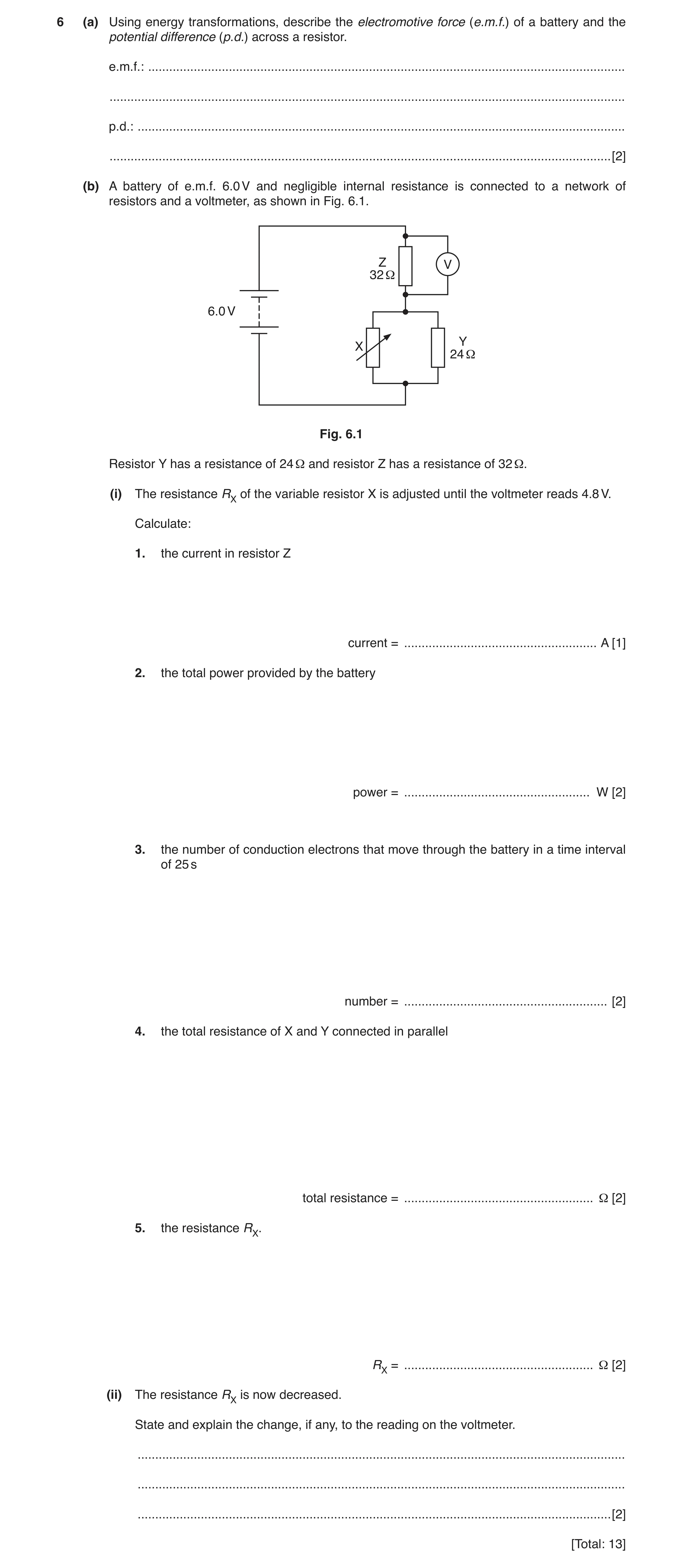
6 (a) Using energy transformations, describe the electromotive force (e.m.f.) of a battery and the potential difference (p.d.) across a resistor. e.m.f.: … … p.d.: … … [2] (b) A battery of e.m.f. 6.0 V and negligible internal resistance is connected to a network of resistors and a voltmeter, as shown in Fig. 6.1. Z V 32 Ω 6.0 V Y X 24 Ω Fig. 6.1 Resistor Y has a resistance of 24 Ω and resistor Z has a resistance of 32 Ω. (i) The resistance RX of the variable resistor X is adjusted until the voltmeter reads 4.8 V. Calculate: 1. the current in resistor Z current = … A [1] 2. the total power provided by the battery power = … W [2] 3. the number of conduction electrons that move through the battery in a time interval of 25 s number = … [2] 4. the total resistance of X and Y connected in parallel total resistance = … Ω [2] 5. the resistance RX. Ω [2] RX = … (ii) The resistance RX is now decreased. State and explain the change, if any, to the reading on the voltmeter. … … … [2] [Total: 13]
13 marks
Mark scheme: 6(a) e.m.f.: energy transferred from chemical to electrical (per unit charge) B1 p.d.: energy transferred from electrical to thermal (per unit charge) B1 Question Answer Marks 6(b)(i) 1 I = 4.8 / 32 = 0.15 A A1 2 P = EI or P = VI or P = I 2R or P = V 2 / R = 6.0 × 0.15 or 0.152 × 40 or 6.02 / 40 C1 = 0.90 W A1 3 number = It / e = [0.15 × 25] / 1.6 × 10⁻¹⁹ C1 = 2.3 × 10¹⁹ A1 or Q = 0.15 × 25 (= 3.75) number = 3.75 / 1.6 × 10⁻¹⁹ (C1) = 2.3 × 10¹⁹ (A1) 4 4.8 / 6.0 = 32 / (RXY + 32) or 1.2 / 6.0 = RXY / (RXY + 32) or 4.8 / 1.2 = 32 / RXY C1 RXY = 8.0 Ω A1 Alternative methods: RXY = (6.0 – 4.8) / 0.15 or (C1) = 8.0 Ω (A1) or 6.0 = 0.15 (32 + RXY) (C1) RXY = 40 – 32 = 8.0 Ω (A1) Question Answer Marks 6(b)(i) 5 1 / 8.0 = 1 / RX + 1 / 24 C1 Rx = 12 Ω A1 Alternative method: IZ = 4.8 / 32 = 0.15 and IY = 1.2 / 24 = 0.05 IX = 0.15 – 0.05 (= 0.10) (C1) RX = 1.2 / 0.10 = 12 Ω (A1) 6(b)(ii) total resistance decreases M1 (so voltmeter) reading increases A1
This question in 9702/22 Feb/March 2019
Question 7 9702/23 May/June 2019
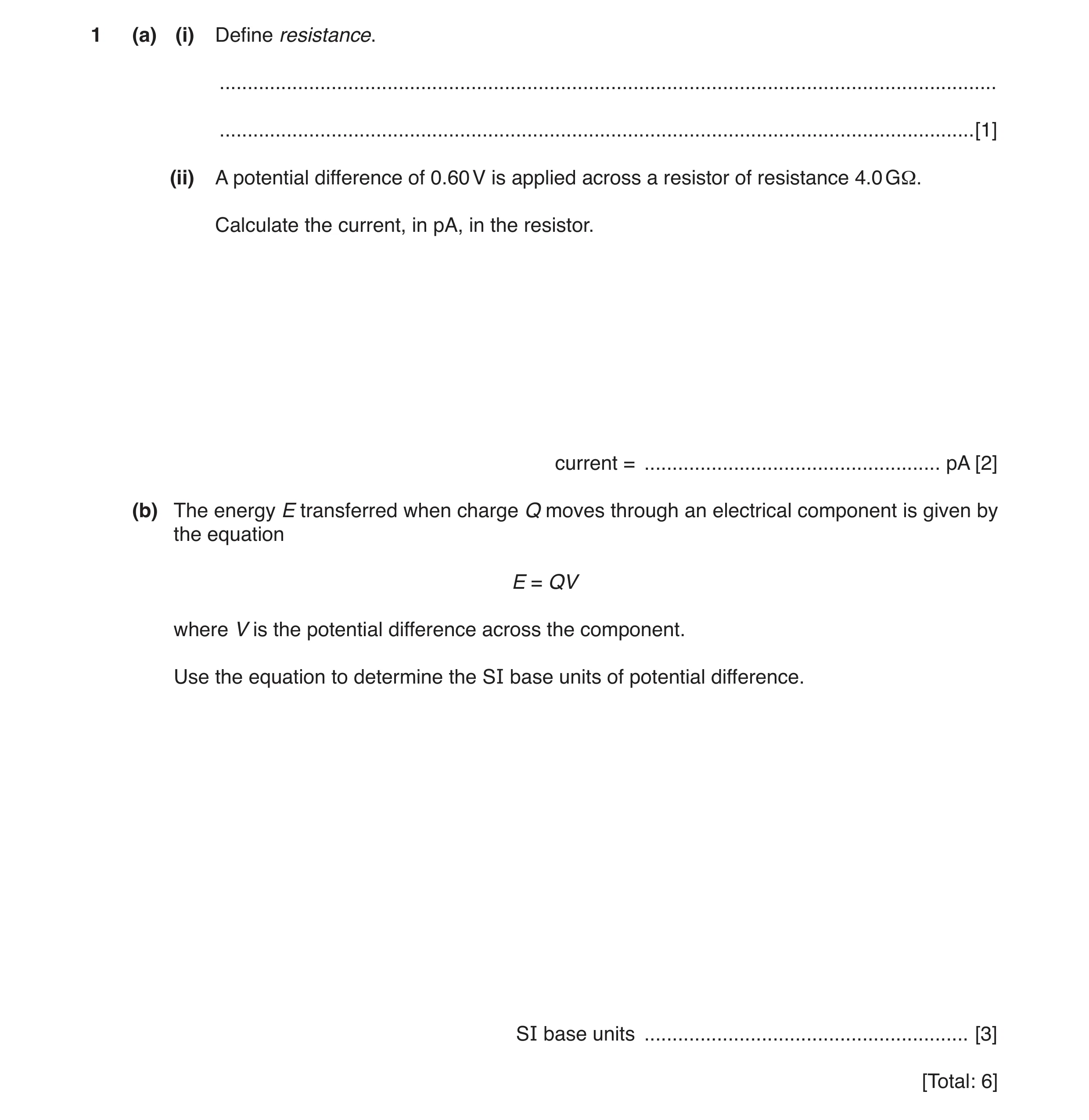
1 (a) (i) Define resistance. … … [1] (ii) A potential difference of 0.60 V is applied across a resistor of resistance 4.0 GΩ. Calculate the current, in pA, in the resistor. current = … pA [2] (b) The energy E transferred when charge Q moves through an electrical component is given by the equation E = QV where V is the potential difference across the component. Use the equation to determine the SI base units of potential difference. SI base units … [3] [Total: 6]
6 marks
Mark scheme: 1(a)(i) potential difference / current B1 1(a)(ii) R = 4.0 × 10⁹ (Ω) C1 I = 0.60 / 4.0 × 109 = 1.5 × 10⁻¹⁰ (A) I = 150 pA A1 1(b) units of energy: kg m2 s–2 C1 units of charge: A s C1 units of potential difference: (kg m2 s–2 / A s =) kg m2 A–1 s–3 A1
This question in 9702/23 May/June 2019
Q8 · A cylindrical disc of mass 0.24 kg has a circular cross-sectional area A, as shown in Fig 9702/23 May/June 2019
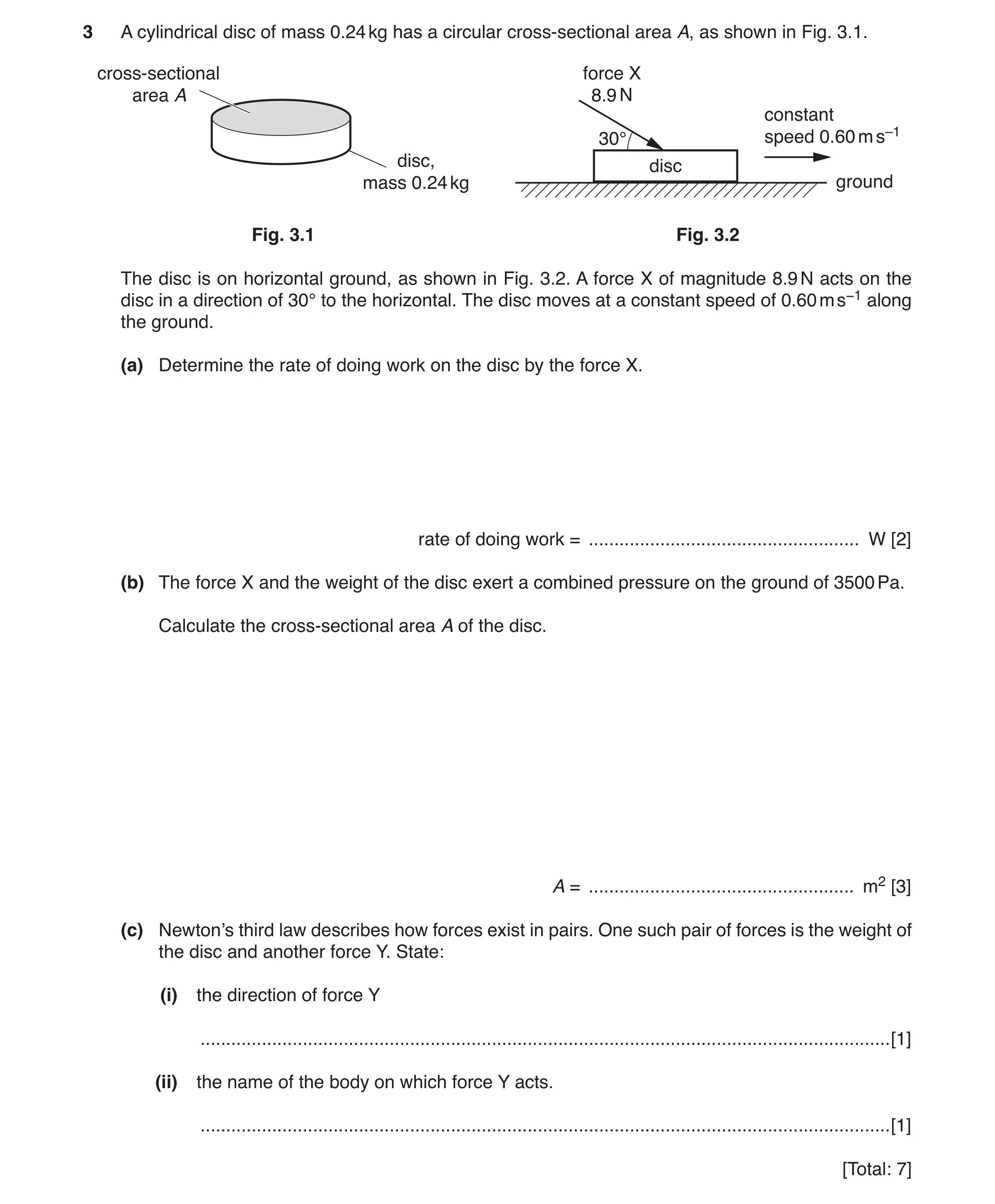
3 A cylindrical disc of mass 0.24 kg has a circular cross-sectional area A, as shown in Fig. 3.1. cross-sectional force X area A 8.9 N constant 30° speed 0.60 m s–1 disc, disc mass 0.24 kg ground Fig. 3.1 Fig. 3.2 The disc is on horizontal ground, as shown in Fig. 3.2. A force X of magnitude 8.9 N acts on the disc in a direction of 30° to the horizontal. The disc moves at a constant speed of 0.60 m s−1 along the ground. (a) Determine the rate of doing work on the disc by the force X. rate of doing work = … W [2] (b) The force X and the weight of the disc exert a combined pressure on the ground of 3500 Pa. Calculate the cross-sectional area A of the disc. A = … m2 [3] (c) Newton’s third law describes how forces exist in pairs. One such pair of forces is the weight of the disc and another force Y. State: (i) the direction of force Y … [1] (ii) the name of the body on which force Y acts. … [1] [Total: 7]
7 marks
Mark scheme: 3(a) P = Fv C1 P = 8.9 cos 30° × 0.60 = 4.6 W A1 3(b) p = F / A C1 F = 8.9 sin 30° + (0.24 × 9.81) ( = 6.80 N) C1 A = 6.80 / 3500 = 1.9 × 10⁻³ m2 A1 3(c)(i) upwards/up B1 3(c)(ii) the Earth/planet B1
This question in 9702/23 May/June 2019
Q9 · Define electric potential difference (p.d.) 9702/21 Oct/Nov 2019
6 (a) Define electric potential difference (p.d.). … … [1] (b) The variation with potential difference V of the current I in a semiconductor diode is shown in Fig. 6.1. 30 25 I / mA 20 15 10 5 0 0 0.5 1.0 V / V Fig. 6.1 Use Fig. 6.1 to describe qualitatively the variation of the resistance of the diode as V increases from 0 to 1.0 V. … … … … [2] (c) The diode in (b) is part of the circuit shown in Fig. 6.2. 2.0 V 15 mA 60 Ω X Y Fig. 6.2 The cell of electromotive force (e.m.f.) 2.0 V and negligible internal resistance is connected in series with the diode and resistors X and Y. The resistance of Y is 60 Ω. The current in the cell is 15 mA. (i) Use Fig. 6.1 to determine the resistance of the diode. resistance = … Ω [3] (ii) Calculate: 1. the resistance of X resistance = … Ω [3] 2. the ratio power dissipated in resistor Y total power produced by the cell. ratio = … [2]
11 marks
Mark scheme: 6(a) work done / charge or energy (transferred from electrical to other forms) / charge B1 6(b) for V < 0.25 V resistance is infinite/very high (as current is zero) B1 for V > 0.25 V resistance decreases (as V increases) B1 6(c)(i) R = V / I C1 = 0.75 / (15 × 10–3) C1 = 50 Ω A1 Question Answer Marks 6(c)(ii) 1. VY = 15 × 10–3 × 60 (= 0.90 V) C1 VX = 2.0 – 0.90 – 0.75 (= 0.35 V) C1 RX = 0.35 / (15 × 10–3) = 23 Ω A1 or total R = 60 + 50 + RX (C1) 60 + 50 + RX = 2.0 / (15 × 10–3) (C1) RX = 23 Ω (A1) 2. P = VI or P = EI or P = I2R or P = V2 / R C1 ratio = ( ) 2 3 3 15 10 60 2.0 15 10 − − × × × × or 3 3 0.90 15 10 2.0 15 10 − − × × × × or ( ) 2 3 0.90 / 60 2.0 15 10− × × = 0.45 A1
This question in 9702/21 Oct/Nov 2019
Q10 · A battery of electromotive force (e.m.f.) 12 V and negligible internal resistance is… 9702/23 Oct/Nov 2019
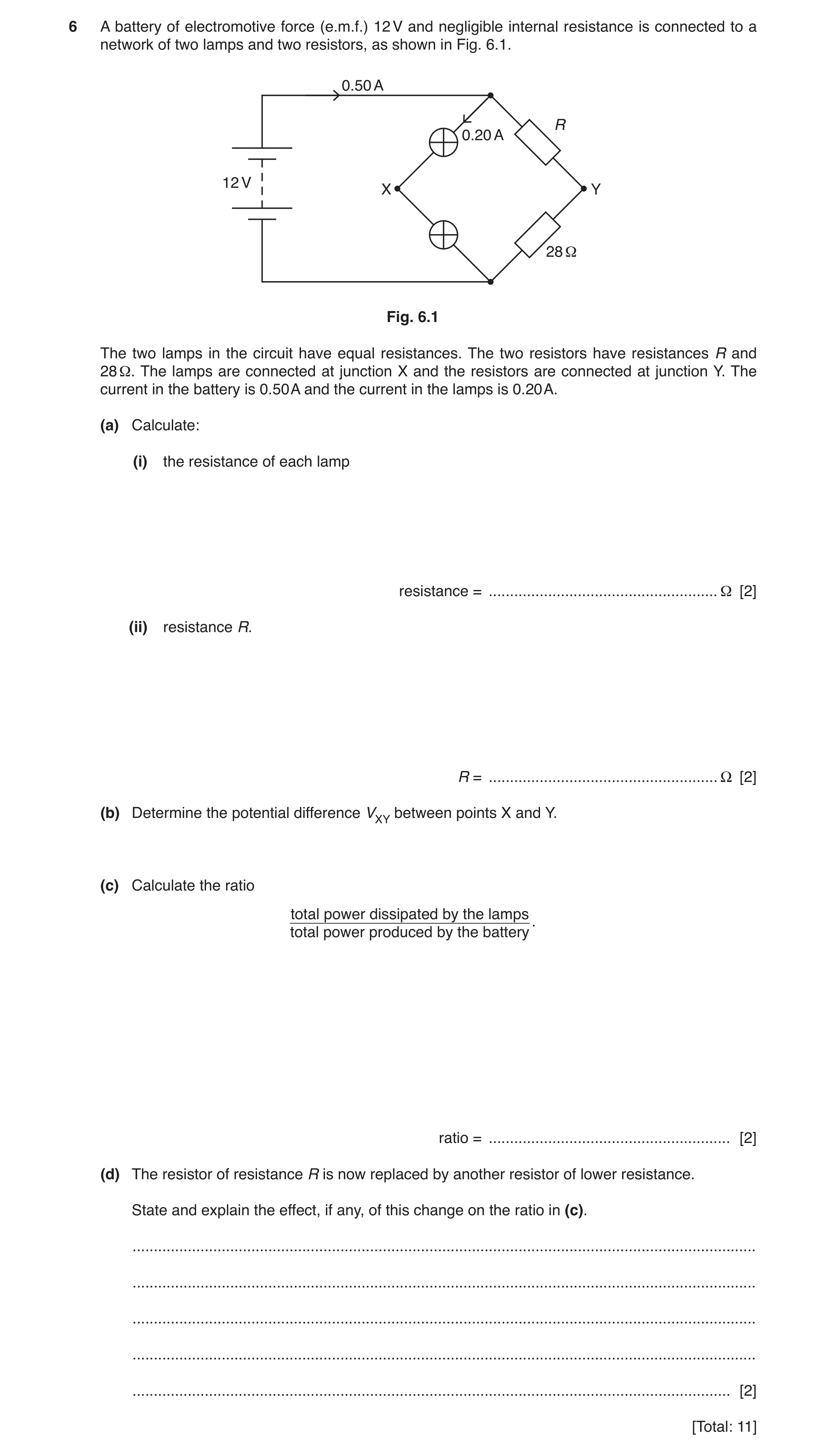
6 A battery of electromotive force (e.m.f.) 12 V and negligible internal resistance is connected to a network of two lamps and two resistors, as shown in Fig. 6.1. 0.50 A R 0.20 A 12 V X Y 28 Ω Fig. 6.1 The two lamps in the circuit have equal resistances. The two resistors have resistances R and 28 Ω. The lamps are connected at junction X and the resistors are connected at junction Y. The current in the battery is 0.50 A and the current in the lamps is 0.20 A. (a) Calculate: (i) the resistance of each lamp resistance = … Ω [2] (ii) resistance R. R = … Ω [2] (b) Determine the potential difference VXY between points X and Y. (c) Calculate the ratio total power dissipated by the lamps . total power produced by the battery ratio = … [2] (d) The resistor of resistance R is now replaced by another resistor of lower resistance. State and explain the effect, if any, of this change on the ratio in (c). … … … … … [2] [Total: 11]
11 marks
Mark scheme: 6(a)(i) C1 resistance = (12 / 0.20) / 2 or 6 / 0.20 = 30 Ω A1 6(a)(ii) I = 0.50 – 0.20 (= 0.30 A) C1 R + 28 = 12 / 0.30 (= 40 Ω) R = 12 Ω A1 Question Answer Marks 6(b) p.d. across lamp = 0.20 × 30 (= 6.0 V) C1 p.d. across R = 0.30 × 12 (= 3.6 V) C1 VXY = 6.0 – 3.6 = 2.4 V A1 or p.d. across lamp = 0.20 × 30 (= 6.0 V) (C1) p.d. across 28 Ω resistor = 0.30 × 28 (= 8.4 V) (C1) VXY = 8.4 – 6.0 = 2.4 V (A1) 6(c) P = VI or P = EI or P = I2R or P = V2 / R C1 ratio = (6.0 × 0.20) × 2 / (12 × 0.50) or 0.20 / 0.50 = 0.40 A1 6(d) no change to V across lamps, so power in lamps unchanged or current in battery/total current increases (and e.m.f. the same) so power produced by battery increases B1 both the above statements and so the ratio decreases B1
This question in 9702/23 Oct/Nov 2019
Question 11 9702/22 Feb/March 2020
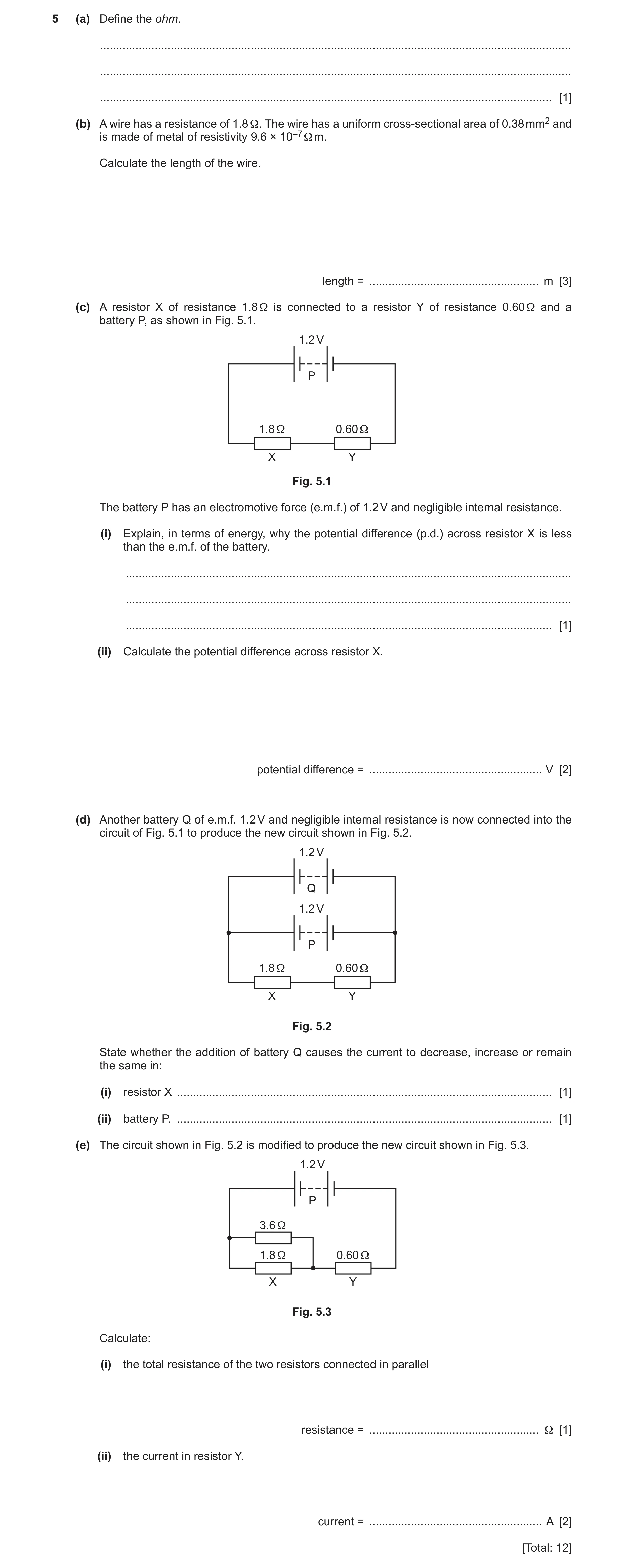
5 (a) Define the ohm. … … … [1] (b) A wire has a resistance of 1.8 Ω. The wire has a uniform cross-sectional area of 0.38 mm2 and is made of metal of resistivity 9.6 × 10⁻⁷ Ω m. Calculate the length of the wire. length = … m [3] (c) A resistor X of resistance 1.8 Ω is connected to a resistor Y of resistance 0.60 Ω and a battery P, as shown in Fig. 5.1. 1.2 V P 1.8 Ω 0.60 Ω X Y Fig. 5.1 The battery P has an electromotive force (e.m.f.) of 1.2 V and negligible internal resistance. (i) Explain, in terms of energy, why the potential difference (p.d.) across resistor X is less than the e.m.f. of the battery. … … … [1] (ii) Calculate the potential difference across resistor X. potential difference = … V [2] (d) Another battery Q of e.m.f. 1.2 V and negligible internal resistance is now connected into the circuit of Fig. 5.1 to produce the new circuit shown in Fig. 5.2. 1.2 V Q 1.2 V P 1.8 Ω 0.60 Ω X Y Fig. 5.2 State whether the addition of battery Q causes the current to decrease, increase or remain the same in: (i) resistor X … [1] (ii) battery P. … [1] (e) The circuit shown in Fig. 5.2 is modified to produce the new circuit shown in Fig. 5.3. 1.2 V P 3.6 Ω 1.8 Ω 0.60 Ω X Y Fig. 5.3 Calculate: (i) the total resistance of the two resistors connected in parallel resistance = … Ω [1] (ii) the current in resistor Y. current = … A [2] [Total: 12]
12 marks
Mark scheme: 5(a) volt / ampere B1 5(b) R = ρ L / A C1 L = (1.8 × 0.38 × 10–6) / 9.6 × 10⁻⁷ C1 = 0.71 m A1 5(c)(i) thermal energy is dissipated in resistor Y B1 5(c)(ii) V / 1.2 = 1.8 / (1.8 + 0.6) C1 V = 0.90 V A1 or I = 1.2 / (1.8 + 0.6) (= 0.50) (C1) V = 0.50 × 1.8 = 0.90 V (A1) 5(d)(i) remain the same B1 5(d)(ii) decrease B1 5(e)(i) 1 / R = 1 / 1.8 + 1 / 3.6 R = 1.2 Ω A1 Question Answer Marks 5(e)(ii) I = 1.2 / (1.2 + 0.60) C1 = 0.67 A A1 or VY = 1.2 × 0.60 / (1.2 + 0.60) (= 0.40) (C1) I = 0.40 / 0.60 = 0.67 A (A1)
This question in 9702/22 Feb/March 2020
Question 12 9702/23 May/June 2020
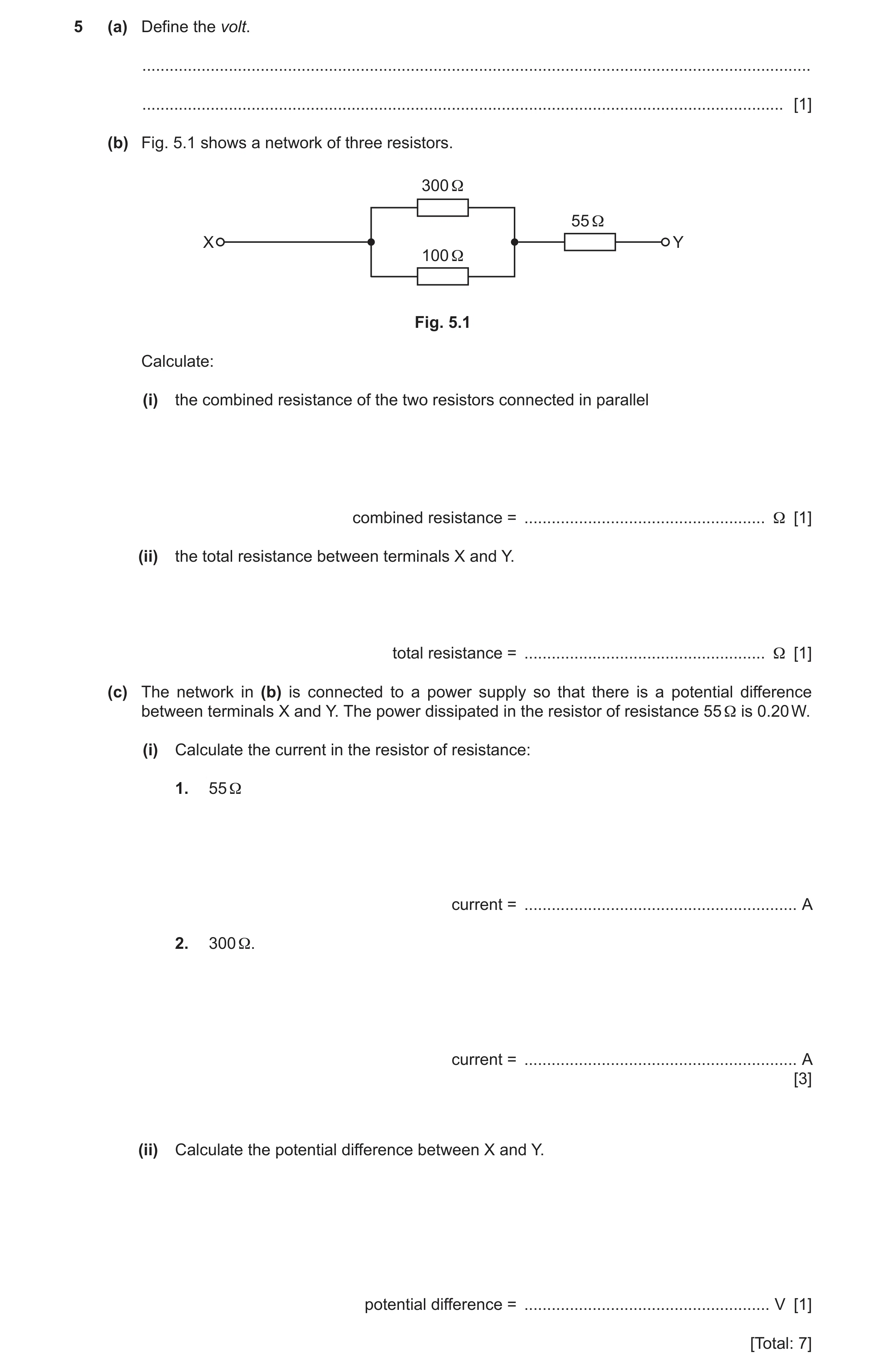
5 (a) Define the volt. … … [1] (b) Fig. 5.1 shows a network of three resistors. 300 Ω 55 Ω X Y 100 Ω Fig. 5.1 Calculate: (i) the combined resistance of the two resistors connected in parallel combined resistance = … Ω [1] (ii) the total resistance between terminals X and Y. total resistance = … Ω [1] (c) The network in (b) is connected to a power supply so that there is a potential difference between terminals X and Y. The power dissipated in the resistor of resistance 55 Ω is 0.20 W. (i) Calculate the current in the resistor of resistance: 1. 55 Ω current = … A 2. 300 Ω. current = … A [3] (ii) Calculate the potential difference between X and Y. potential difference = … V [1] [Total: 7]
7 marks
Mark scheme: 5(a) joule per coulomb B1 5(b)(i) 1 / R = 1 / R1 + 1 / R2 = 1 / 300 + 1 / 200 R = 75 Ω A1 5(b)(ii) R = 75 + 55 = 130 Ω A1 5(c)(i) 1. P = I2R or P = VI and V = IR C1 I = (0.20 / 55)0.5 = 0.060 A A1 2. I = 0.060 / 4 = 0.015 A A1 5(c)(ii) potential difference = 130 × 0.060 = 7.8 V A1 or potential difference = (300 × 0.015) + (55 × 0.060) = 7.8 V (other valid methods are also possible) (A1)
This question in 9702/23 May/June 2020
Question 13 9702/21 Oct/Nov 2020
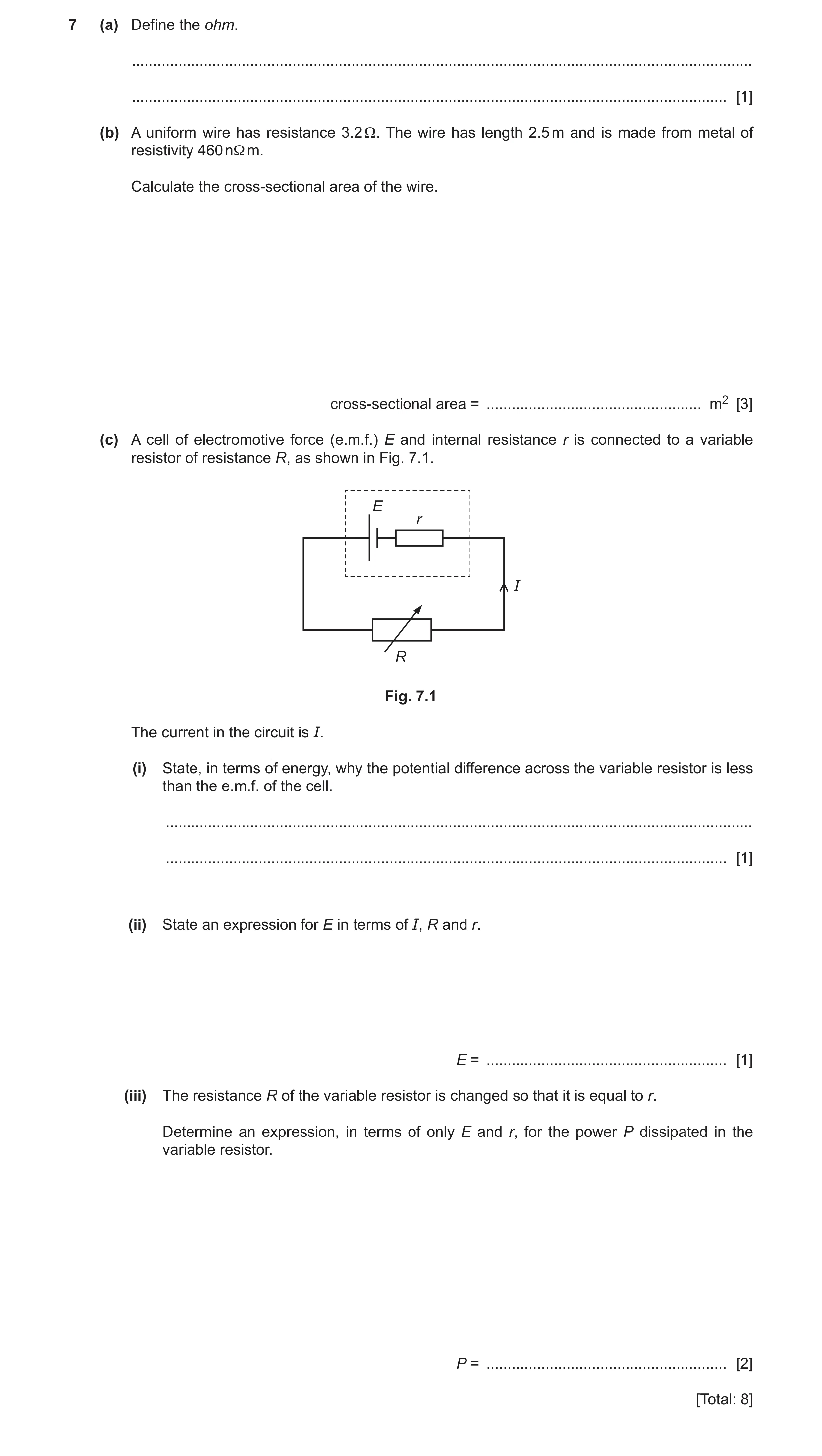
7 (a) Define the ohm. … … [1] (b) A uniform wire has resistance 3.2 Ω. The wire has length 2.5 m and is made from metal of resistivity 460 nΩ m. Calculate the cross-sectional area of the wire. cross-sectional area = … m2 [3] (c) A cell of electromotive force (e.m.f.) E and internal resistance r is connected to a variable resistor of resistance R, as shown in Fig. 7.1. E r I R Fig. 7.1 The current in the circuit is I. (i) State, in terms of energy, why the potential difference across the variable resistor is less than the e.m.f. of the cell. … … [1] (ii) State an expression for E in terms of I, R and r. E = … [1] (iii) The resistance R of the variable resistor is changed so that it is equal to r. Determine an expression, in terms of only E and r, for the power P dissipated in the variable resistor. P = … [2] [Total: 8]
8 marks
Mark scheme: 7(a) volt / ampere B1 7(b) R = ρL / A C1 A = 460 × 10–9 × 2.5 / 3.2 C1 = 3.6 × 10⁻⁷ m2 A1 7(c)(i) energy is dissipated in the internal resistance/r B1 7(c)(ii) E = IR + Ir or E = I (R + r) B1 7(c)(iii) P = I2R or P = I2r C1 I = E / 2r (so) P = E2 / 4r A1
This question in 9702/21 Oct/Nov 2020
Q14 · Define electric potential difference (p.d.) 9702/23 Oct/Nov 2020
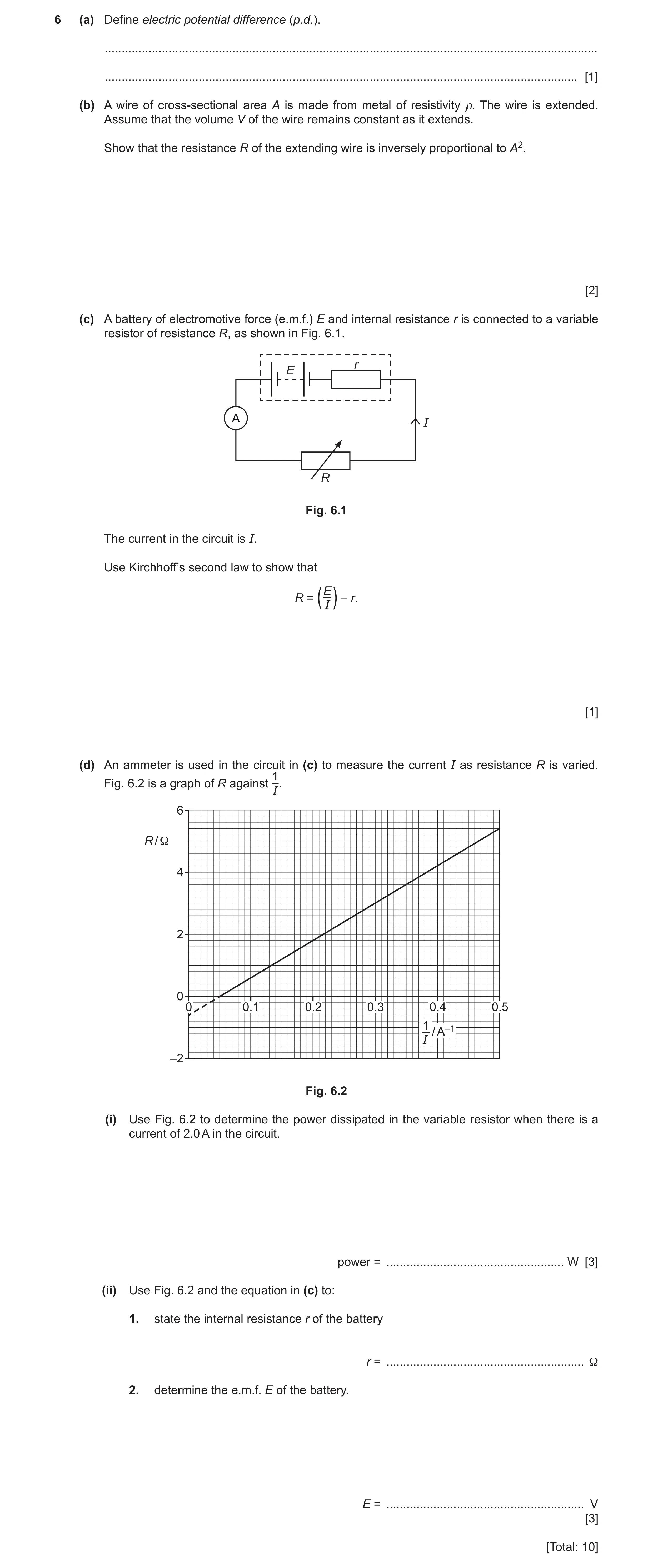
6 (a) Define electric potential difference (p.d.). … … [1] (b) A wire of cross-sectional area A is made from metal of resistivity ρ. The wire is extended. Assume that the volume V of the wire remains constant as it extends. Show that the resistance R of the extending wire is inversely proportional to A2. [2] (c) A battery of electromotive force (e.m.f.) E and internal resistance r is connected to a variable resistor of resistance R, as shown in Fig. 6.1. r E A I R Fig. 6.1 The current in the circuit is I. Use Kirchhoff’s second law to show that R = – r. (EI) [1] (d) An ammeter is used in the circuit in (c) to measure the current I as resistance R is varied. 1 Fig. 6.2 is a graph of R against I. 6 R / Ω 4 2 0 0 0.1 0.2 0.3 0.4 0.5 1 / A–1 I –2 Fig. 6.2 (i) Use Fig. 6.2 to determine the power dissipated in the variable resistor when there is a current of 2.0 A in the circuit. power = … W [3] (ii) Use Fig. 6.2 and the equation in (c) to: 1. state the internal resistance r of the battery r = … Ω 2. determine the e.m.f. E of the battery. E = … V [3] [Total: 10]
10 marks
Mark scheme: 6(a) ( ) ( ) work done /energy transferred from electrical to other forms charge B1 6(b) R = ρL / A B1 V = LA and (so) R = ρV / A2 (with ρ and V constant) B1 6(c) E = IR + Ir or E = I(R + r) or E – Ir = IR and R = (E / I) – r A1 6(d)(i) P = I 2R or P = IV or P = V2 / R C1 R = 5.4 (Ω) or V = 10.8 (V) C1 P = 2.02 × 5.4 = 22 W A1 6(d)(ii) 1. r = 0.60 Ω A1 2. E = gradient C1 = e.g. 5.4 / 0.45 = 12 V A1
This question in 9702/23 Oct/Nov 2020
Q15 · Define the electromotive force (e.m.f.) of a source 9702/23 May/June 2021
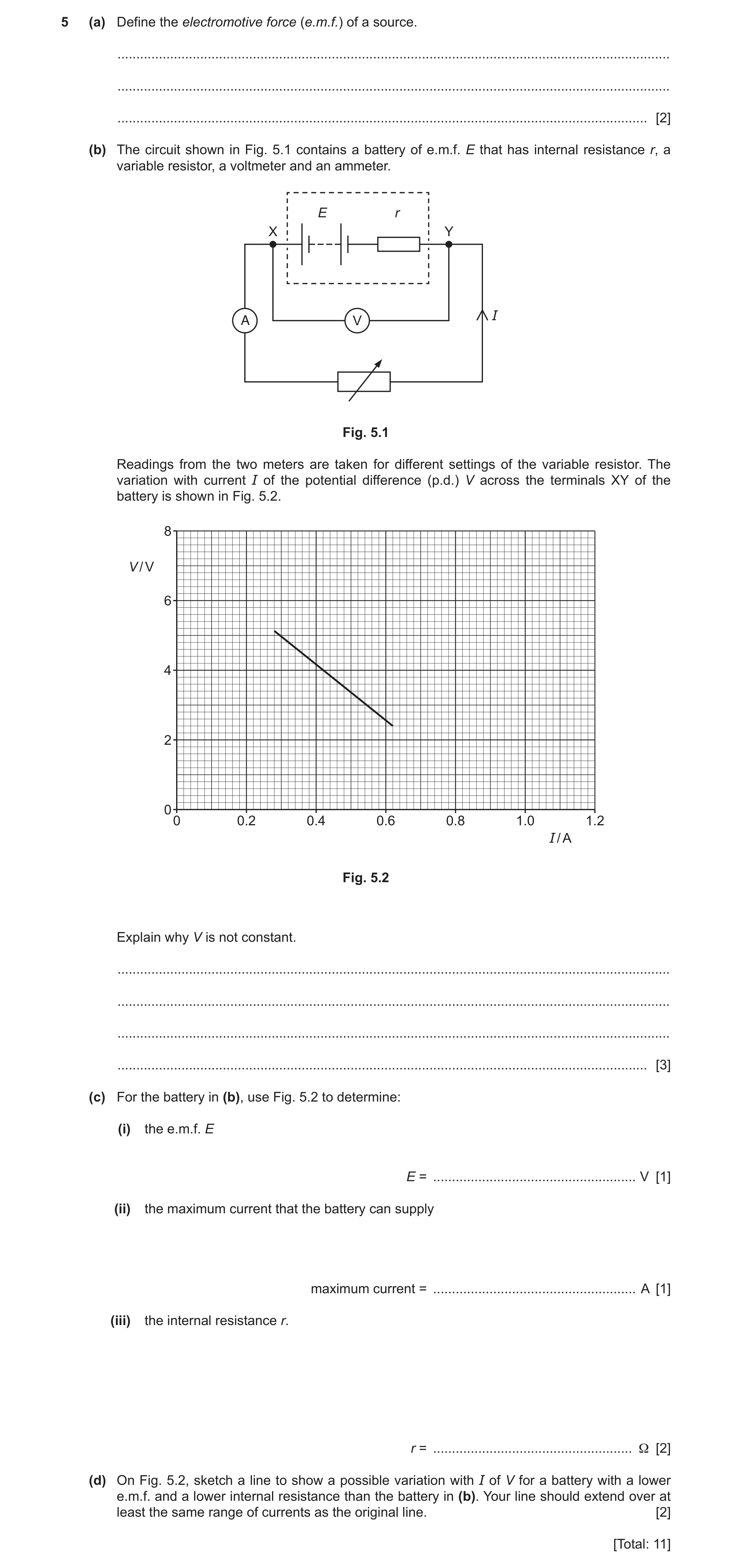
5 (a) Define the electromotive force (e.m.f.) of a source. … … … [2] (b) The circuit shown in Fig. 5.1 contains a battery of e.m.f. E that has internal resistance r, a variable resistor, a voltmeter and an ammeter. E r X Y A V I Fig. 5.1 Readings from the two meters are taken for different settings of the variable resistor. The variation with current I of the potential difference (p.d.) V across the terminals XY of the battery is shown in Fig. 5.2. 8 V / V 6 4 2 0 0 0.2 0.4 0.6 0.8 1.0 1.2 I / A Fig. 5.2 Explain why V is not constant. … … … … [3] (c) For the battery in (b), use Fig. 5.2 to determine: (i) the e.m.f. E E = … V [1] (ii) the maximum current that the battery can supply maximum current = … A [1] (iii) the internal resistance r. r = … Ω [2] (d) On Fig. 5.2, sketch a line to show a possible variation with I of V for a battery with a lower e.m.f. and a lower internal resistance than the battery in (b). Your line should extend over at least the same range of currents as the original line. [2] [Total: 11]
11 marks
Mark scheme: 5(a) energy per unit charge B1 energy transferred by source driving charge around the complete circuit or energy transferred from other forms to electrical energy B1 5(b) there is a p.d. across the internal resistance/r B1 change in current/I results in a change in p.d. across the internal resistance B1 V = E – p.d. across internal resistance or change in p.d. across r causes a change in V (as e.m.f. is constant) B1 5(c)(i) E = 7.4 V A1 5(c)(ii) maximum current = 0.92 A A1 5(c)(iii) r = E / IMAX or (–)gradient C1 e.g. r = 7.4 / 0.92 = 8.0 Ω A1 5(d) straight line with negative gradient that is smaller in magnitude than the original line B1 line which would have intercept on V-axis below the original line B1 Question Answer Marks
This question in 9702/23 May/June 2021
Question 16 9702/22 Oct/Nov 2021
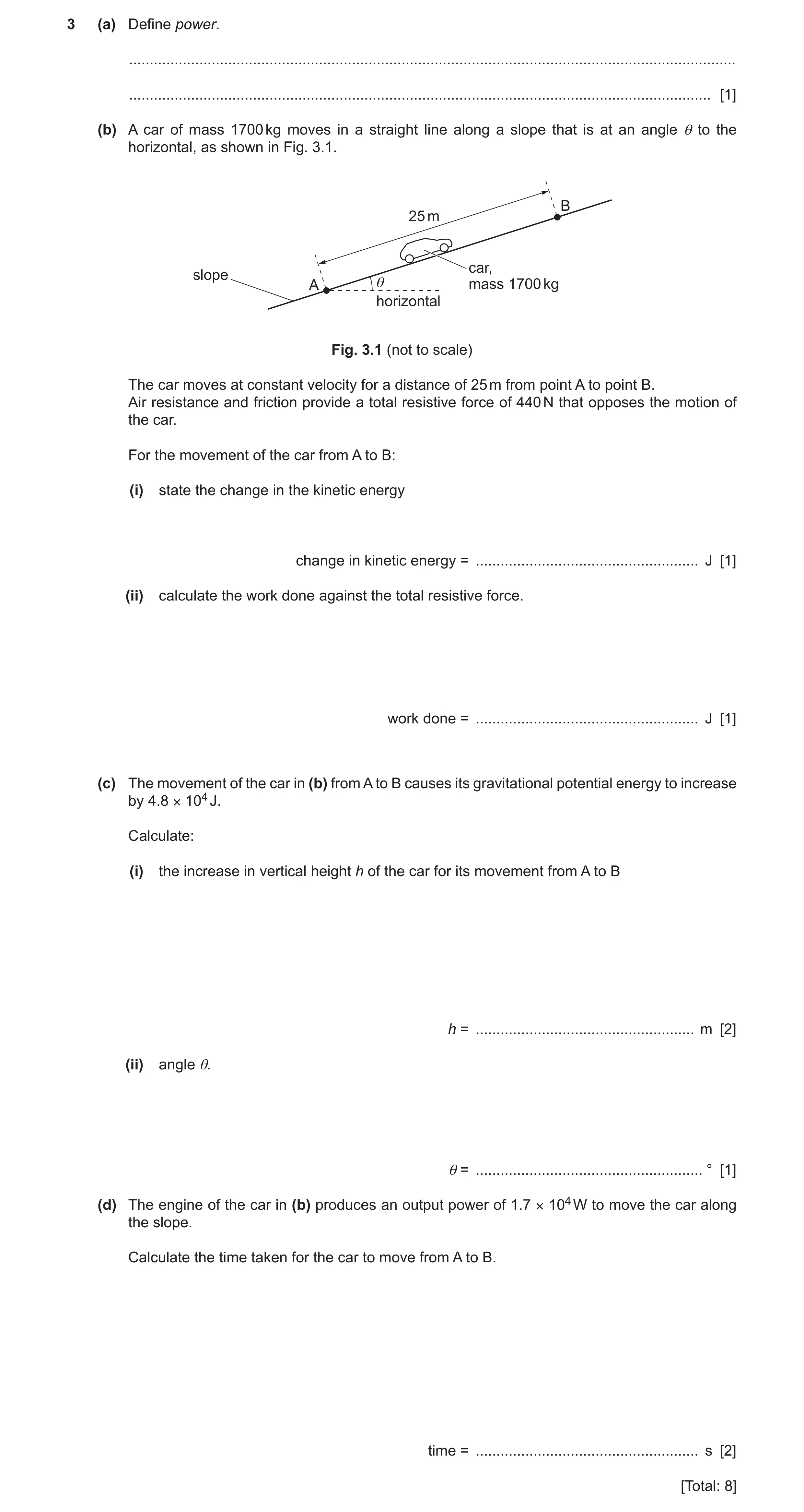
3 (a) Define power. … … [1] (b) A car of mass 1700 kg moves in a straight line along a slope that is at an angle θ to the horizontal, as shown in Fig. 3.1. B 25 m car, slope A θ mass 1700 kg horizontal Fig. 3.1 (not to scale) The car moves at constant velocity for a distance of 25 m from point A to point B. Air resistance and friction provide a total resistive force of 440 N that opposes the motion of the car. For the movement of the car from A to B: (i) state the change in the kinetic energy change in kinetic energy = … J [1] (ii) calculate the work done against the total resistive force. work done = … J [1] (c) The movement of the car in (b) from A to B causes its gravitational potential energy to increase by 4.8 × 10⁴ J. Calculate: (i) the increase in vertical height h of the car for its movement from A to B h = … m [2] (ii) angle θ. θ = … ° [1] (d) The engine of the car in (b) produces an output power of 1.7 × 10⁴ W to move the car along the slope. Calculate the time taken for the car to move from A to B. time = … s [2] [Total: 8]
8 marks
Mark scheme: 3(a) work (done) / time (taken) B1 3(b)(i) zero / 0 J A1 3(b)(ii) work done = 440 × 25 = 1.1 × 10⁴ J A1 3(c)(i) (Δ)E(P) = mg(Δ)h C1 h = 4.8 × 10⁴ / (1700 × 9.81) = 2.9 m A1 3(c)(ii) θ = sin–1 (2.9 / 25) = 6.7° A1 3(d) work done = 4.8 × 10⁴ + 1.1 × 10⁴ (= 5.9 × 10⁴ J) C1 time = 5.9 × 10⁴ / 1.7 × 104 = 3.5 s A1
This question in 9702/22 Oct/Nov 2021
Q17 · A cell of electromotive force (e.m.f.) 0.48 V is connected to a metal wire X, as shown in… 9702/22 Oct/Nov 2021
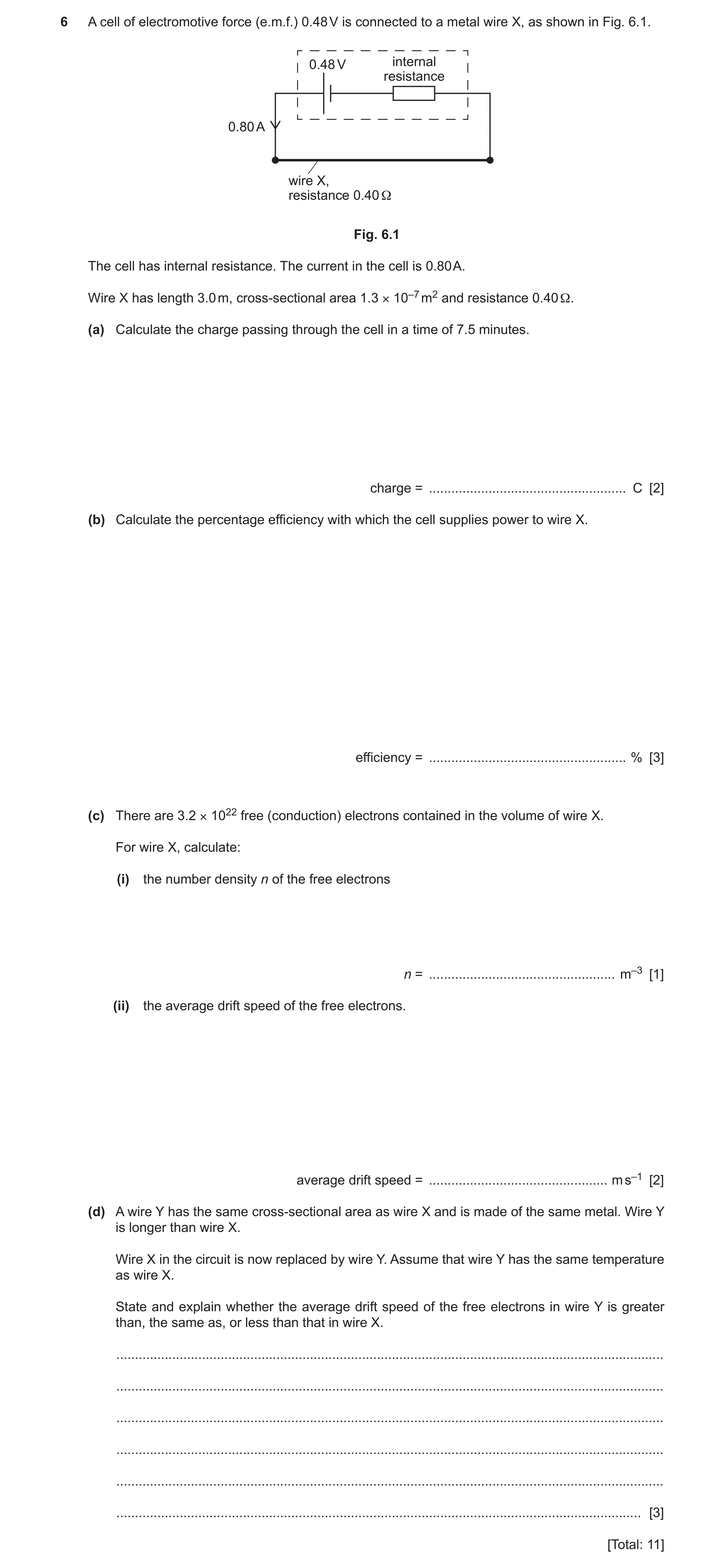
6 A cell of electromotive force (e.m.f.) 0.48 V is connected to a metal wire X, as shown in Fig. 6.1. 0.48 V internal resistance 0.80 A wire X, resistance 0.40 Ω Fig. 6.1 The cell has internal resistance. The current in the cell is 0.80 A. Wire X has length 3.0 m, cross-sectional area 1.3 × 10⁻⁷ m2 and resistance 0.40 Ω. (a) Calculate the charge passing through the cell in a time of 7.5 minutes. charge = … C [2] (b) Calculate the percentage efficiency with which the cell supplies power to wire X. efficiency = … % [3] (c) There are 3.2 × 10²² free (conduction) electrons contained in the volume of wire X. For wire X, calculate: (i) the number density n of the free electrons n = … m–3 [1] (ii) the average drift speed of the free electrons. average drift speed = … m s–1 [2] (d) A wire Y has the same cross-sectional area as wire X and is made of the same metal. Wire Y is longer than wire X. Wire X in the circuit is now replaced by wire Y. Assume that wire Y has the same temperature as wire X. State and explain whether the average drift speed of the free electrons in wire Y is greater than, the same as, or less than that in wire X. … … … … … … [3] [Total: 11]
11 marks
Mark scheme: 6(a) C1 = 0.80 × 7.5 × 60 = 360 C A1 6(b) P = EI or P = VI or P = I2R or P = V2 / R C1 0.802 × 0.40 (= 0.256 W) or 0.48 × 0.80 (= 0.384 W) C1 efficiency = (0.256 / 0.384) × 100 = 67% A1 6(c)(i) n = 3.2 × 10²² / (1.3 × 10–7 × 3.0) = 8.2 × 1028 m–3 A1 6(c)(ii) I = Anvq v = 0.80 / (1.3 × 10–7 × 8.2 × 1028 × 1.60 × 10–19) C1 = 4.7 × 10⁻⁴ m s–1 A1 6(d) (wire Y has) larger resistance / resistance increases M1 (wire Y has) smaller current / current decreases M1 (average drift) speed is less (in wire Y) A1
This question in 9702/22 Oct/Nov 2021
Question 18 9702/21 Oct/Nov 2022
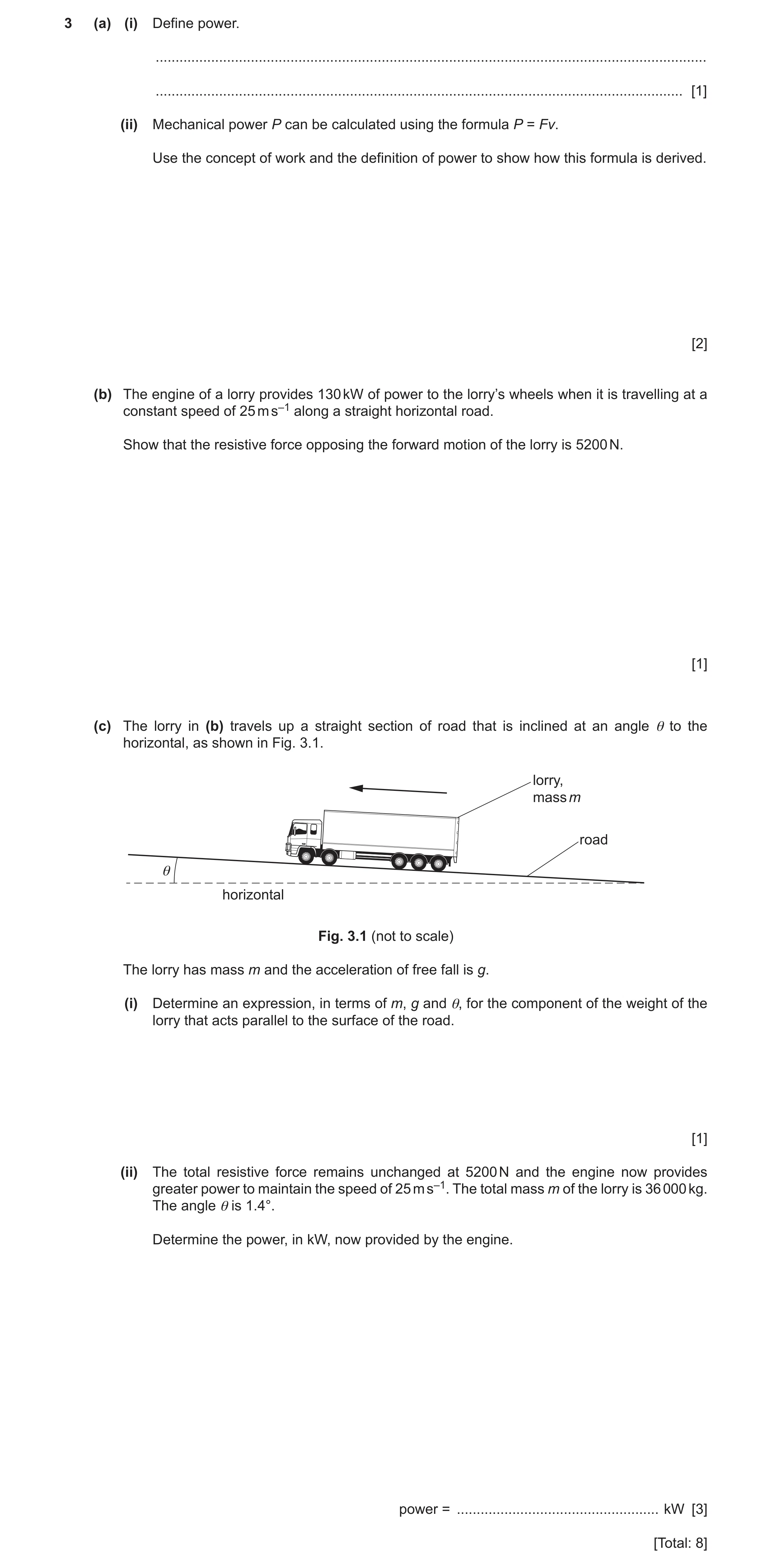
3 (a) (i) Define power. … … [1] (ii) Mechanical power P can be calculated using the formula P = Fv. Use the concept of work and the definition of power to show how this formula is derived. [2] (b) The engine of a lorry provides 130 kW of power to the lorry’s wheels when it is travelling at a constant speed of 25 m s–1 along a straight horizontal road. Show that the resistive force opposing the forward motion of the lorry is 5200 N. [1] (c) The lorry in (b) travels up a straight section of road that is inclined at an angle θ to the horizontal, as shown in Fig. 3.1. lorry, mass m road θ horizontal Fig. 3.1 (not to scale) The lorry has mass m and the acceleration of free fall is g. (i) Determine an expression, in terms of m, g and θ, for the component of the weight of the lorry that acts parallel to the surface of the road. [1] (ii) The total resistive force remains unchanged at 5200 N and the engine now provides greater power to maintain the speed of 25 m s–1. The total mass m of the lorry is 36 000 kg. The angle θ is 1.4°. Determine the power, in kW, now provided by the engine. power = … kW [3] [Total: 8]
8 marks
Mark scheme: 3(a)(i) work done per unit time B1 3(a)(ii) W = Fs B1 P = Fs / t and (so) P = Fv B1 3(b) (F =) 130 103 / 25 = 5200 (N) A1 3(c)(i) (component of weight =) mg sin A1 3(c)(ii) F (along slope due to weight) = 36 000 9.81 sin 1.4° C1 ( = 8600 N) (total) F = 5200 + 36 000 9.81 sin 1.4° C1 ( = 13 800 N) P = 13 800 25 A1 = 350 103 (W) = 350 kW
This question in 9702/21 Oct/Nov 2022
Q19 · Define the potential difference across a component 9702/22 Feb/March 2023
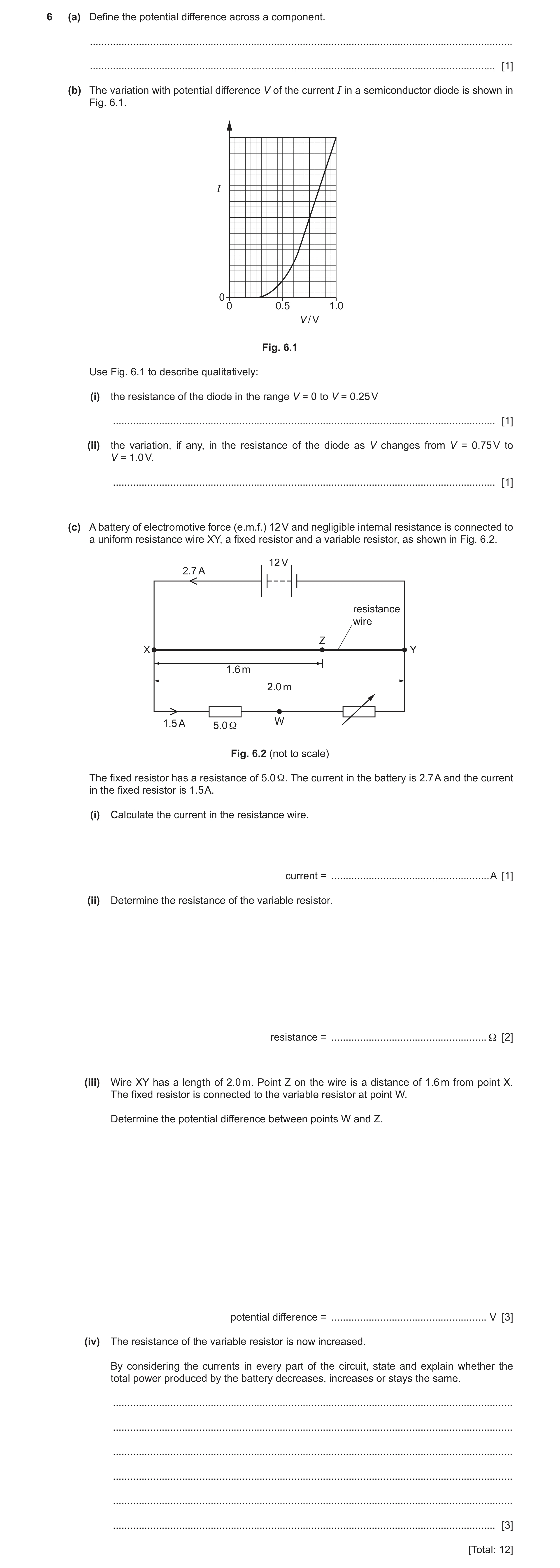
6 (a) Define the potential difference across a component. … … [1] (b) The variation with potential difference V of the current I in a semiconductor diode is shown in Fig. 6.1. I 0 0 0.5 1.0 V / V Fig. 6.1 Use Fig. 6.1 to describe qualitatively: (i) the resistance of the diode in the range V = 0 to V = 0.25 V … [1] (ii) the variation, if any, in the resistance of the diode as V changes from V = 0.75 V to V = 1.0 V. … [1] (c) A battery of electromotive force (e.m.f.) 12 V and negligible internal resistance is connected to a uniform resistance wire XY, a fixed resistor and a variable resistor, as shown in Fig. 6.2. 12 V 2.7 A resistance wire Z X Y 1.6 m 2.0 m 1.5 A 5.0 Ω W Fig. 6.2 (not to scale) The fixed resistor has a resistance of 5.0 Ω. The current in the battery is 2.7 A and the current in the fixed resistor is 1.5 A. (i) Calculate the current in the resistance wire. current = … A [1] (ii) Determine the resistance of the variable resistor. resistance = … Ω [2] (iii) Wire XY has a length of 2.0 m. Point Z on the wire is a distance of 1.6 m from point X. The fixed resistor is connected to the variable resistor at point W. Determine the potential difference between points W and Z. potential difference = … V [3] (iv) The resistance of the variable resistor is now increased. By considering the currents in every part of the circuit, state and explain whether the total power produced by the battery decreases, increases or stays the same. … … … … … … [3] [Total: 12]
12 marks
Mark scheme: 6(a) energy (transferred from electrical to other forms) per unit charge B1 6(b)(i) (resistance is) infinite / very high B1 6(b)(ii) (resistance) decreases (as V increases) B1 6(c)(i) current = 2.7 – 1.5 A1 = 1.2 A 6(c)(ii) 12 = (1.5 5.0) + (1.5 R) or R = (12 / 1.5) – 5.0 C1 R = 3.0 A1 6(c)(iii) V(XZ) = (1.6 / 2.0) 12 (= 9.6 V) C1 V(XW) = 1.5 5.0 (= 7.5 V) C1 potential difference = 9.6 – 7.5 A1 = 2.1 V or V(ZY) = (0.4 / 2.0) 12 (= 2.4 V) (C1) V(WY) = 1.5 3.0 (= 4.5 V) (C1) potential difference = 4.5 – 2.4 (A1) = 2.1 V 6(c)(iv) current in (fixed / variable) resistor decreases B1 current in (resistance) wire is unchanged B1 (so) current in battery decreases, (same e.m.f. so) power decreases B1
This question in 9702/22 Feb/March 2023
Q20 · A train travels at a constant high speed along a straight horizontal track towards an… 9702/21 Oct/Nov 2023
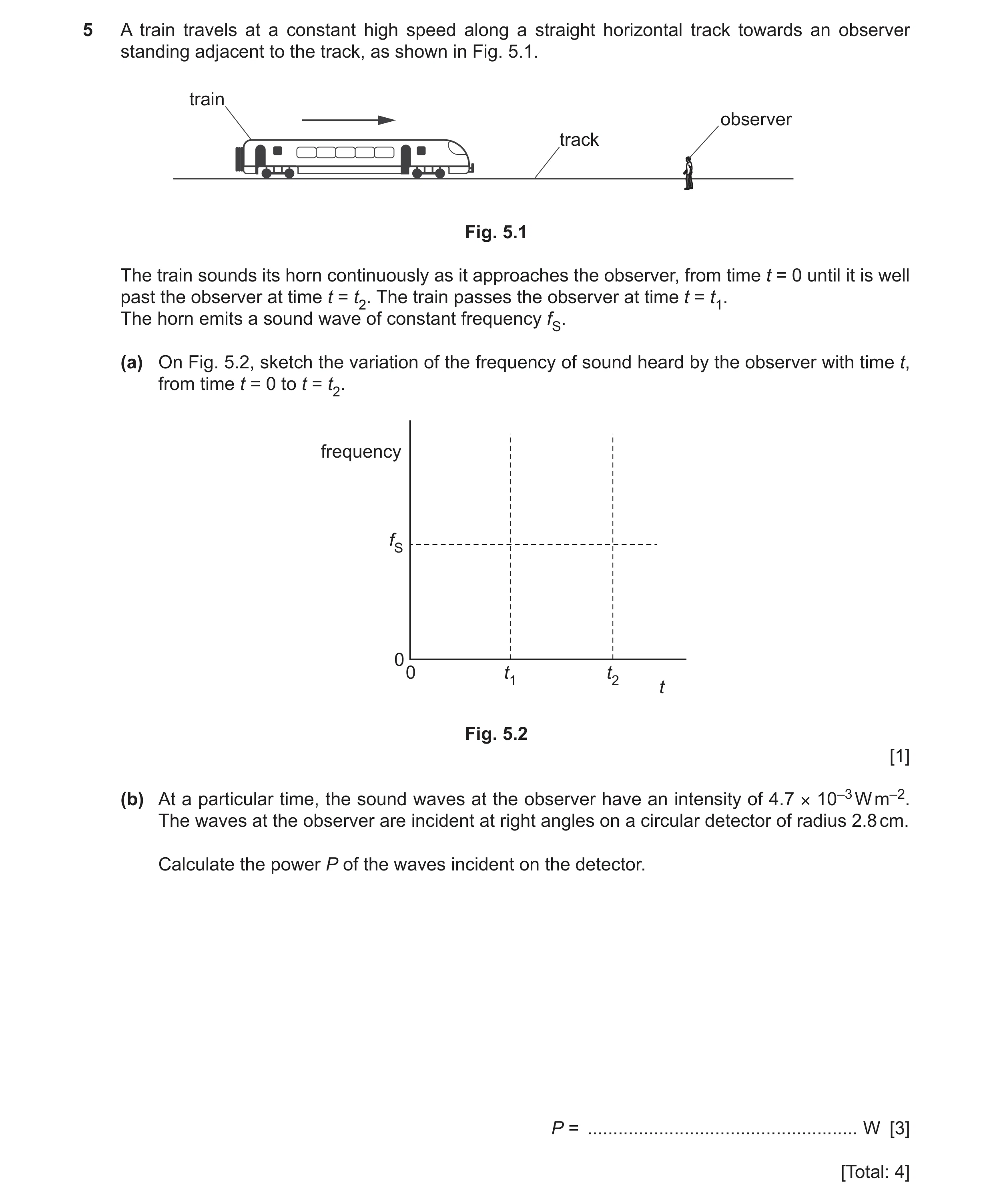
5 A train travels at a constant high speed along a straight horizontal track towards an observer standing adjacent to the track, as shown in Fig. 5.1. train observer track Fig. 5.1 The train sounds its horn continuously as it approaches the observer, from time t = 0 until it is well past the observer at time t = t2. The train passes the observer at time t = t1. The horn emits a sound wave of constant frequency fS. (a) On Fig. 5.2, sketch the variation of the frequency of sound heard by the observer with time t, from time t = 0 to t = t2. frequency fS 0 0 t1 t2 t Fig. 5.2 [1] (b) At a particular time, the sound waves at the observer have an intensity of 4.7 × 10⁻³ W m–2. The waves at the observer are incident at right angles on a circular detector of radius 2.8 cm. Calculate the power P of the waves incident on the detector. P = … W [3] [Total: 4]
4 marks
Mark scheme: 5(a) sketch: approximately horizontal line above horizontal dashed line from t = 0 to t = t1 A1 and approximately horizontal line below horizontal dashed line from t = t1 to t = t2 5(b) I = P / A C1 A = 0.0282 or 2.82 C1 ( = 2.46 10–3 or 24.6) P = 4.7 10–3 2.46 10–3 A1 = 1.2 10–5 W
This question in 9702/21 Oct/Nov 2023
Q21 · Table 1.1 lists some SI quantities 9702/22 Feb/March 2024
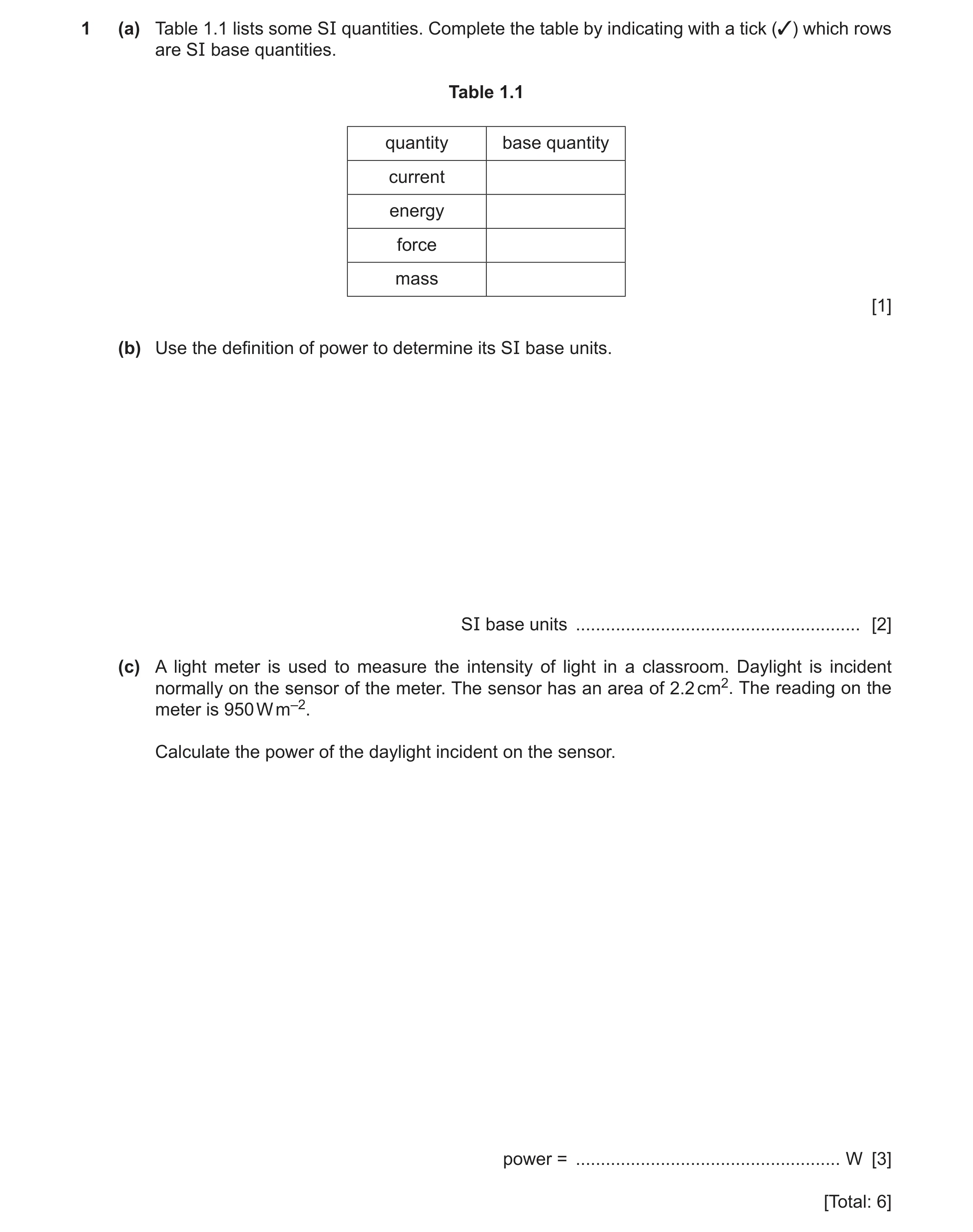
1 (a) Table 1.1 lists some SI quantities. Complete the table by indicating with a tick (✓) which rows are SI base quantities. Table 1.1 quantity base quantity current energy force mass [1] (b) Use the definition of power to determine its SI base units. SI base units … [2] (c) A light meter is used to measure the intensity of light in a classroom. Daylight is incident normally on the sensor of the meter. The sensor has an area of 2.2 cm2. The reading on the meter is 950 W m–2. Calculate the power of the daylight incident on the sensor. power = … W [3] [Total: 6]
6 marks
Mark scheme: Question Answer Marks 1(a) current and mass only ticked A1 1(b) (power =) work (done) / time C1 units of power = J s–1 A1 = kg m2 s–2 / s = kg m2 s–3 1(c) power = intensity area C1 = 950 2.2 10–4 C1 = 0.21 W A1
This question in 9702/22 Feb/March 2024
Q22 · Define electric potential difference 9702/22 Feb/March 2024
7 (a) Define electric potential difference. … … [1] (b) A cell of electromotive force (e.m.f.) 1.8 V and internal resistance r is connected in parallel with a resistor of resistance 6.0 Ω and a filament lamp, as shown in Fig. 7.1. 1.8 V r A 6.0 Ω S Fig. 7.1 The switch S is open. The ammeter reading is 0.25 A. Determine the internal resistance r of the cell. r = … Ω [3] (c) At time t1 switch S in Fig. 7.1 is closed. Fig. 7.2 shows the variation with time t of the ammeter reading I. I 0 0 t1 t Fig. 7.2 (i) State whether the e.m.f. of the cell after t1 is greater than, less than or the same as it was before t1. … [1] (ii) By considering the effect of the lamp on the total resistance of the circuit, explain the variation of the ammeter reading shown in Fig. 7.2. … … … … … … [3] [Total: 8]
8 marks
Mark scheme: 7(a) energy (transferred) per (unit) charge B1 7(b) V = 0.25 6 C1 =1.5 Ir = E – IR C1 Ir = 1.8 – 1.5 = 0.3 r = 0.3 / 0.25 A1 = 1.2 or (C1) (Total) R = 1.8 / 0.25 = 7.2 E / I = (R + r) 1.8/0.25 = 6 + r (C1) r = 7.2 – 6 (A1) = 1.2 7(c)(i) The same B1 7(c)(ii) Any 3 from: B3 • before t1 / when current constant, the (total) resistance is constant • at t1 / when current increases, the (total) resistance decreases (due to decrease of external resistance) • (after t1) temperature (of lamp) increases (so the resistance of the lamp increases) • (after t1) resistance of lamp increases (so total resistance increases so the current in the ammeter decreases)
This question in 9702/22 Feb/March 2024
Q23 · Lightning occurs when charge builds up in the atmosphere, creating a potential difference… 9702/22 May/June 2024
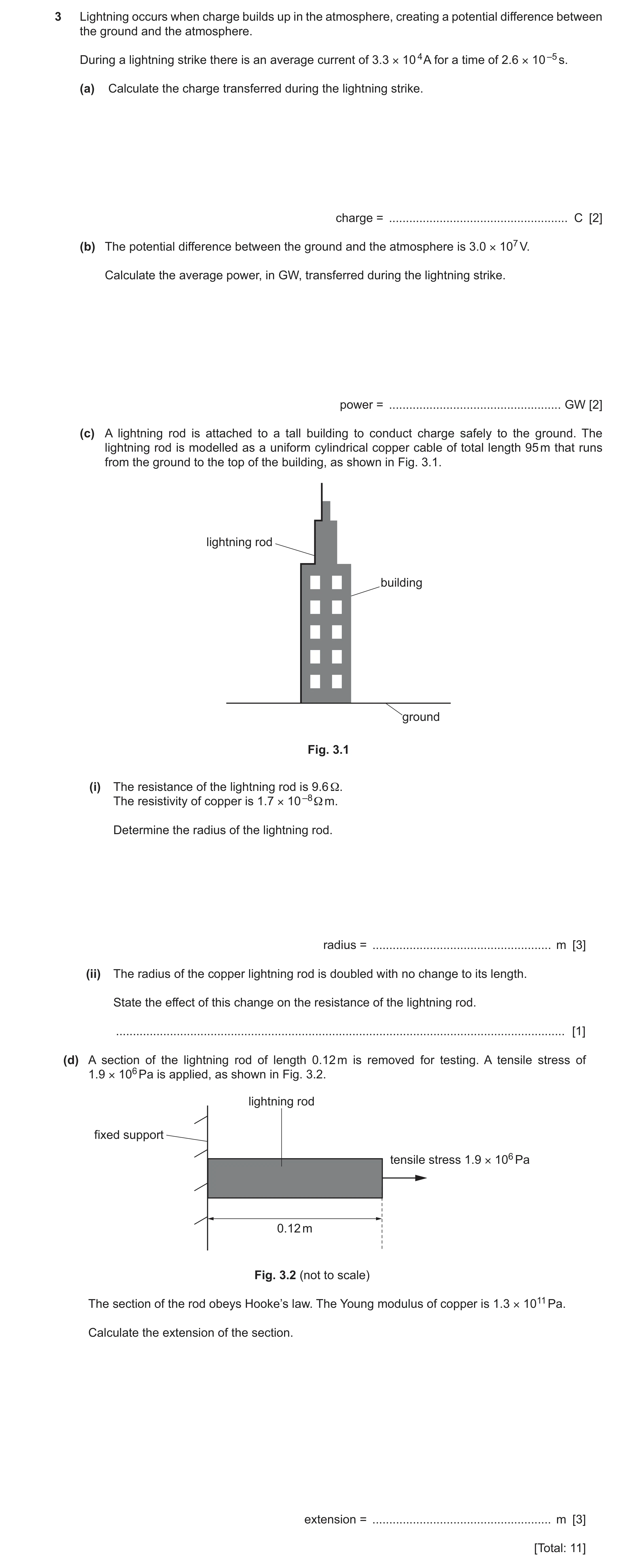
3 Lightning occurs when charge builds up in the atmosphere, creating a potential difference between the ground and the atmosphere. During a lightning strike there is an average current of 3.3 × 10 4 A for a time of 2.6 × 10 –5 s. (a) Calculate the charge transferred during the lightning strike. charge = … C [2] (b) The potential difference between the ground and the atmosphere is 3.0 × 10⁷ V. Calculate the average power, in GW, transferred during the lightning strike. power = … GW [2] (c) A lightning rod is attached to a tall building to conduct charge safely to the ground. The lightning rod is modelled as a uniform cylindrical copper cable of total length 95 m that runs from the ground to the top of the building, as shown in Fig. 3.1. lightning rod building ground Fig. 3.1 (i) The resistance of the lightning rod is 9.6 Ω. The resistivity of copper is 1.7 × 10 –8 Ω m. Determine the radius of the lightning rod. radius = … m [3] (ii) The radius of the copper lightning rod is doubled with no change to its length. State the effect of this change on the resistance of the lightning rod. … [1] (d) A section of the lightning rod of length 0.12 m is removed for testing. A tensile stress of 1.9 × 10⁶ Pa is applied, as shown in Fig. 3.2. lightning rod fixed support tensile stress 1.9 × 10⁶ Pa 0.12 m Fig. 3.2 (not to scale) The section of the rod obeys Hooke’s law. The Young modulus of copper is 1.3 × 10¹¹ Pa. Calculate the extension of the section. extension = … m [3] [Total: 11]
11 marks
Mark scheme: 3(a) C1 = 3.3 104 2.6 10–5 = 0.86 C A1 3(b) P = IV or P = VQ / t or V = IR and P = V 2/R or P = I 2R C1 P = 3.3 104 3.0 107 or P = (3.0 107 0.86) / (2.6 10–5) or P = (3.0 107)2 / 910 or P = (3.3 104)2 910 P = 9.9 1011 (W) = 990 GW A1 3(c)(i) R = L / A C1 9.6 = 1.7 10–8 95 / r 2 C1 r = 2.3 10–4 m A1 3(c)(ii) (resistance) decreases by a factor of four A1 Question Answer Marks 3(d) E = / C1 x = L / E = 1.9 106 0.12 / (1.3 1011) C1 = 1.8 10–6 m A1
This question in 9702/22 May/June 2024
Q24 · A cylindrical copper wire P of length 0.24 m is shown in Fig 9702/22 Feb/March 2025
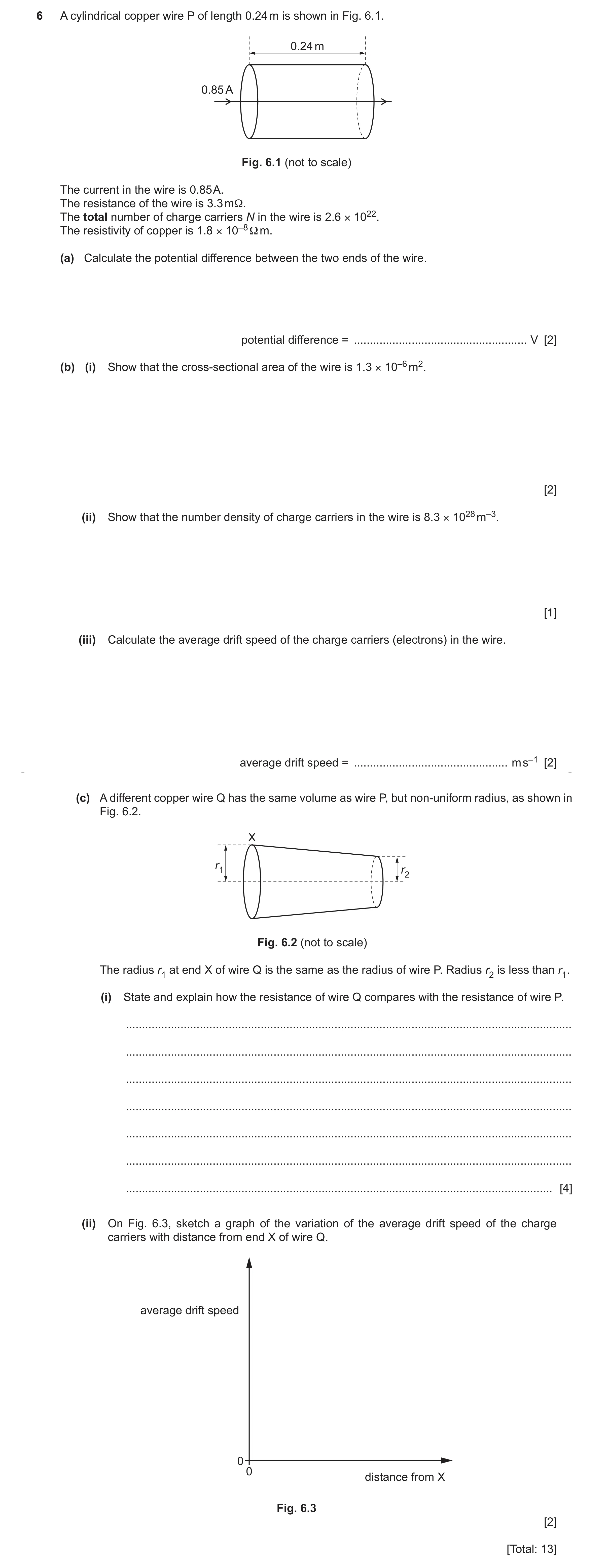
6 A cylindrical copper wire P of length 0.24 m is shown in Fig. 6.1. 0.24 m 0.85 A Fig. 6.1 (not to scale) The current in the wire is 0.85 A. The resistance of the wire is 3.3 mΩ. The total number of charge carriers N in the wire is 2.6 × 10²². The resistivity of copper is 1.8 × 10⁻⁸ Ω m. (a) Calculate the potential difference between the two ends of the wire. potential difference = … V [2] (b) (i) Show that the cross-sectional area of the wire is 1.3 × 10⁻⁶ m2. [2] (ii) Show that the number density of charge carriers in the wire is 8.3 × 1028 m–3. [1] (iii) Calculate the average drift speed of the charge carriers (electrons) in the wire. average drift speed = … m s–1 [2] (c) A different copper wire Q has the same volume as wire P, but non-uniform radius, as shown in Fig. 6.2. X r1 r2 Fig. 6.2 (not to scale) The radius r1 at end X of wire Q is the same as the radius of wire P. Radius r2 is less than r1. (i) State and explain how the resistance of wire Q compares with the resistance of wire P. … … … … … … … [4] (ii) On Fig. 6.3, sketch a graph of the variation of the average drift speed of the charge carriers with distance from end X of wire Q. average drift speed 0 0 distance from X Fig. 6.3 [2] [Total: 13]
13 marks
Mark scheme: 6(a) V = IR C1 = 0.85 3.3 10–3 = 2.8 10–3 V A1 6(b)(i) (A =) L / R C1 = 1.8 10–8 0.24 / 3.3 10–3 = 1.3 10–6 (m2) A1 6(b)(ii) (n =) 2.6 1022 / (1.3 10–6 0.24) = 8.3 1028 (m–3) A1 6(b)(iii) v = I / nAq C1 = 0.85 / (8.3 1028 1.3 10–6 1.6 10–19) = 4.9 10–5 m s–1 A1 OR (C1) v = IL / Nq = 0.85 0.24 / (2.6 1022 1.6 10–19) = 4.9 10–5 m s–1 (A1) 6(c)(i) Length (of Q) is greater (than P) B1 (Average cross-sectional) area (of Q) is less (than P) B1 Resistance is proportional to length / (cross-sectional) area M1 (so) the resistance (of Q) is greater (than P) A1 6(c)(ii) A line starting from a non-zero value of drift speed at distance = 0 B1 A line with an increasing positive gradient B1
This question in 9702/22 Feb/March 2025
Q25 · Define electric potential difference across a component 9702/22 May/June 2025
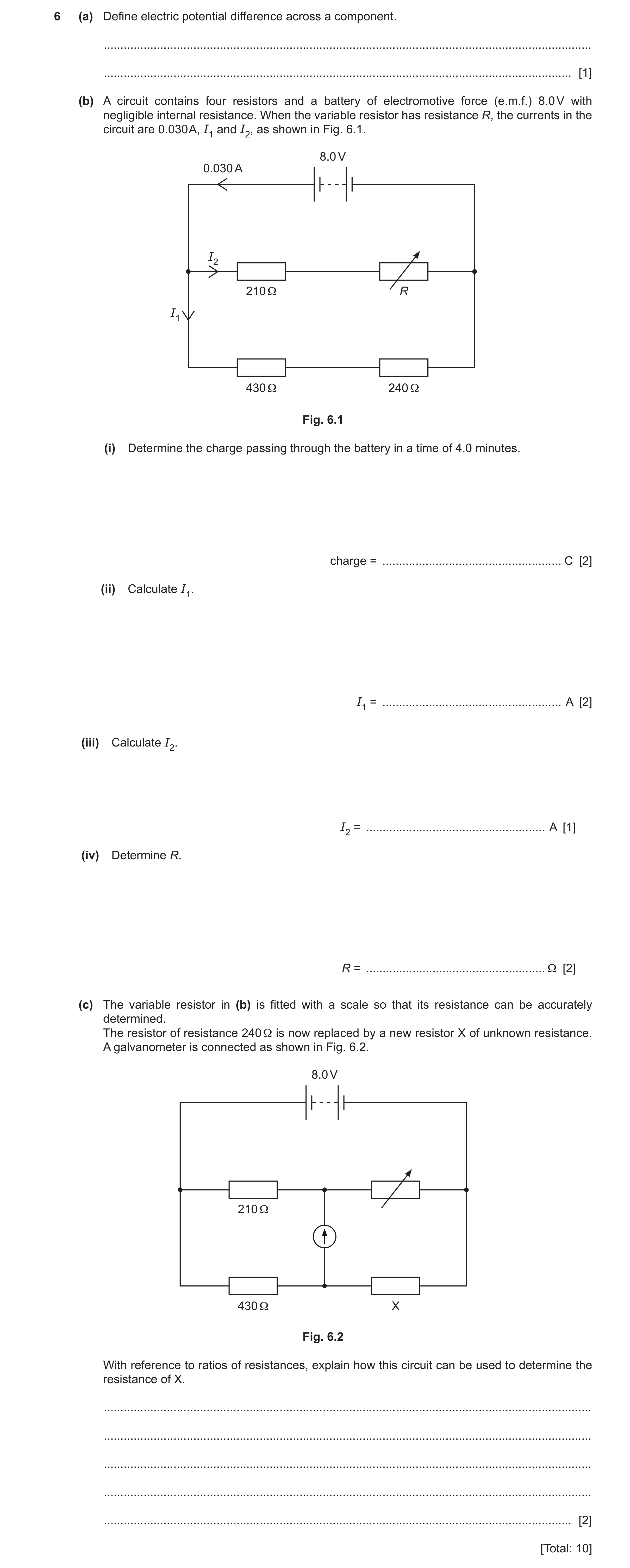
6 (a) Define electric potential difference across a component. … … [1] (b) A circuit contains four resistors and a battery of electromotive force (e.m.f.) 8.0 V with negligible internal resistance. When the variable resistor has resistance R, the currents in the circuit are 0.030 A, I1 and I2, as shown in Fig. 6.1. 8.0 V 0.030 A I2 210 Ω R I1 430 Ω 240 Ω Fig. 6.1 (i) Determine the charge passing through the battery in a time of 4.0 minutes. charge = … C [2] (ii) Calculate I1. I1 = … A [2] (iii) Calculate I2. I2 = … A [1] (iv) Determine R. R = … Ω [2] (c) The variable resistor in (b) is fitted with a scale so that its resistance can be accurately determined. The resistor of resistance 240 Ω is now replaced by a new resistor X of unknown resistance. A galvanometer is connected as shown in Fig. 6.2. 8.0 V 210 Ω 430 Ω X Fig. 6.2 With reference to ratios of resistances, explain how this circuit can be used to determine the resistance of X. … … … … … [2] [Total: 10]
10 marks
Mark scheme: 6(a) energy transferred (to the component) per (unit) charge B1 6(b)(i) Q = It C1 = 0.030 4.0 60 = 7.2 C A1 6(b)(ii) I = V / R C1 I1 = 8.0 / (430+240) = 0.012 A A1 6(b)(iii) I2 = 0.030 – I1 A1 = 0.030 – 0.012 = 0.018 A 6(b)(iv) R = V / I2 C1 = (8.0 – (0.018 210)) / 0.018 = 230 A1 OR (C1) resistance of top branch = 8.0 / 0.018 R = 8.0 / 0.018 – 210 = 230 (A1) OR (C1) total circuit resistance = 8.0 / 0.030 = 267 1 / 267 = 1 / (210 + R) + 1 / (430 + 240) 1 / 267 – 1 / 670 = 1 / (210 +R) 210 + R = 443 R = 230 (A1) 6(c) (When) the galvanometer reads 0 (A) M1 The ratio of the resistances in the top branch will equal the ratio of the resistances in the bottom branch (so the resistance A1 of X can be determined) OR (A1) The ratio of the left pair of resistances will equal the ratio of the right pair of resistances
This question in 9702/22 May/June 2025
Q26 · A car of mass 1500 kg is travelling along a straight horizontal road at constant velocity… 9702/23 May/June 2025
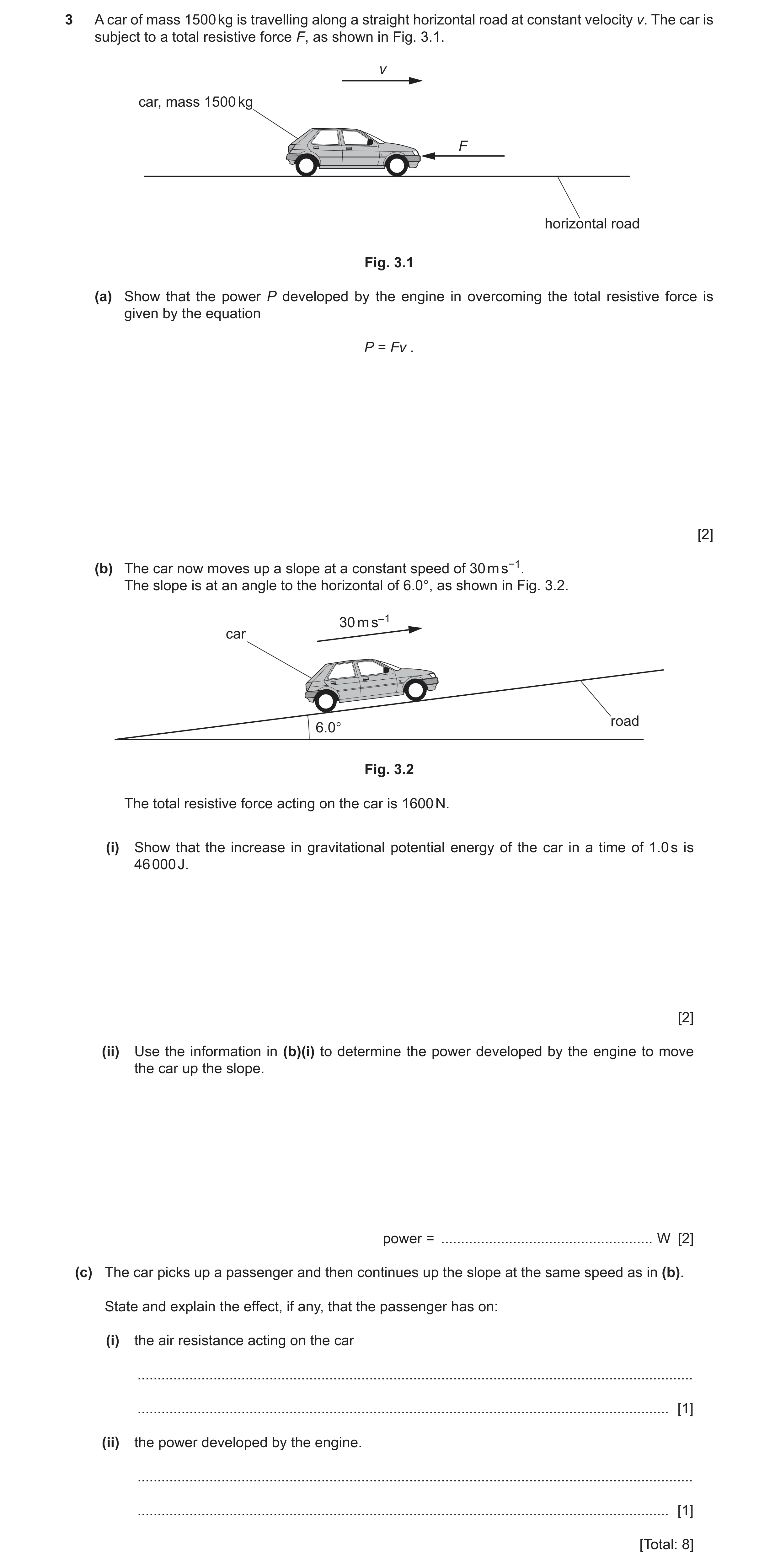
3 A car of mass 1500 kg is travelling along a straight horizontal road at constant velocity v. The car is subject to a total resistive force F, as shown in Fig. 3.1. v car, mass 1500 kg F horizontal road Fig. 3.1 (a) Show that the power P developed by the engine in overcoming the total resistive force is given by the equation P = Fv . [2] (b) The car now moves up a slope at a constant speed of 30 m s−1. The slope is at an angle to the horizontal of 6.0°, as shown in Fig. 3.2. 30 m s–1 car road 6.0° Fig. 3.2 The total resistive force acting on the car is 1600 N. (i) Show that the increase in gravitational potential energy of the car in a time of 1.0 s is 46 000 J. [2] (ii) Use the information in (b)(i) to determine the power developed by the engine to move the car up the slope. power = … W [2] (c) The car picks up a passenger and then continues up the slope at the same speed as in (b). State and explain the effect, if any, that the passenger has on: (i) the air resistance acting on the car … … [1] (ii) the power developed by the engine. … … [1] [Total: 8]
8 marks
Mark scheme: 3(a) W = Fd B1 P = Fd / t = Fv or P = Fvt / t = Fv B1 3(b)(i) ()E(P) = mg()h C1 increase of gravitational potential energy of car in 1.0 s A1 = 1500 9.81 30 sin 6.0 = 46 000 J 3(b)(ii) (Power to overcome total resistive forces) = 1600 30 C1 = 48 000 W power = 48 000 + 46 000 A1 = 9.4 104 W 3(c)(i) Air resistance is the same, as the speed is the same B1 3(c)(ii) Mass / weight has increased so (power will) increase B1
This question in 9702/23 May/June 2025
 4 / 40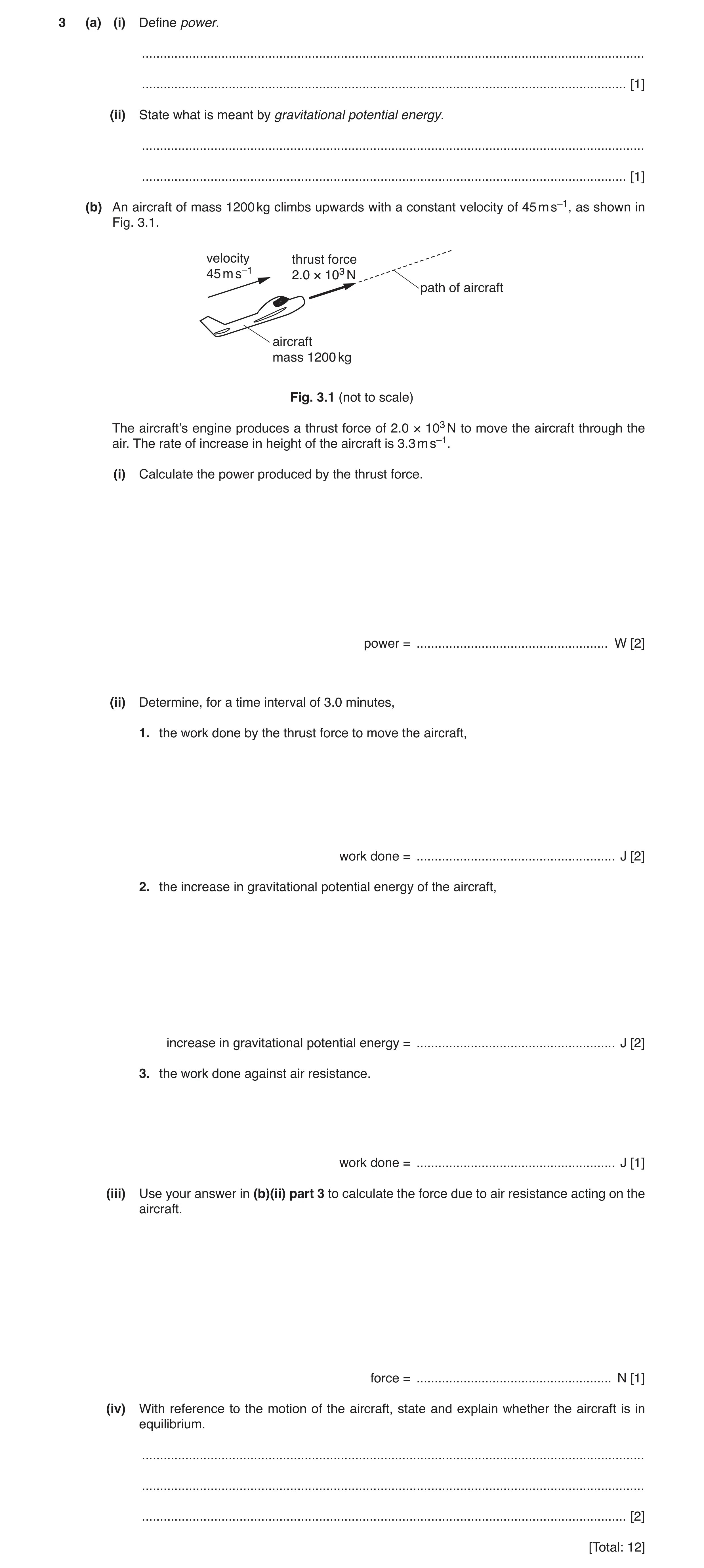
 10 / 40
 11 / 40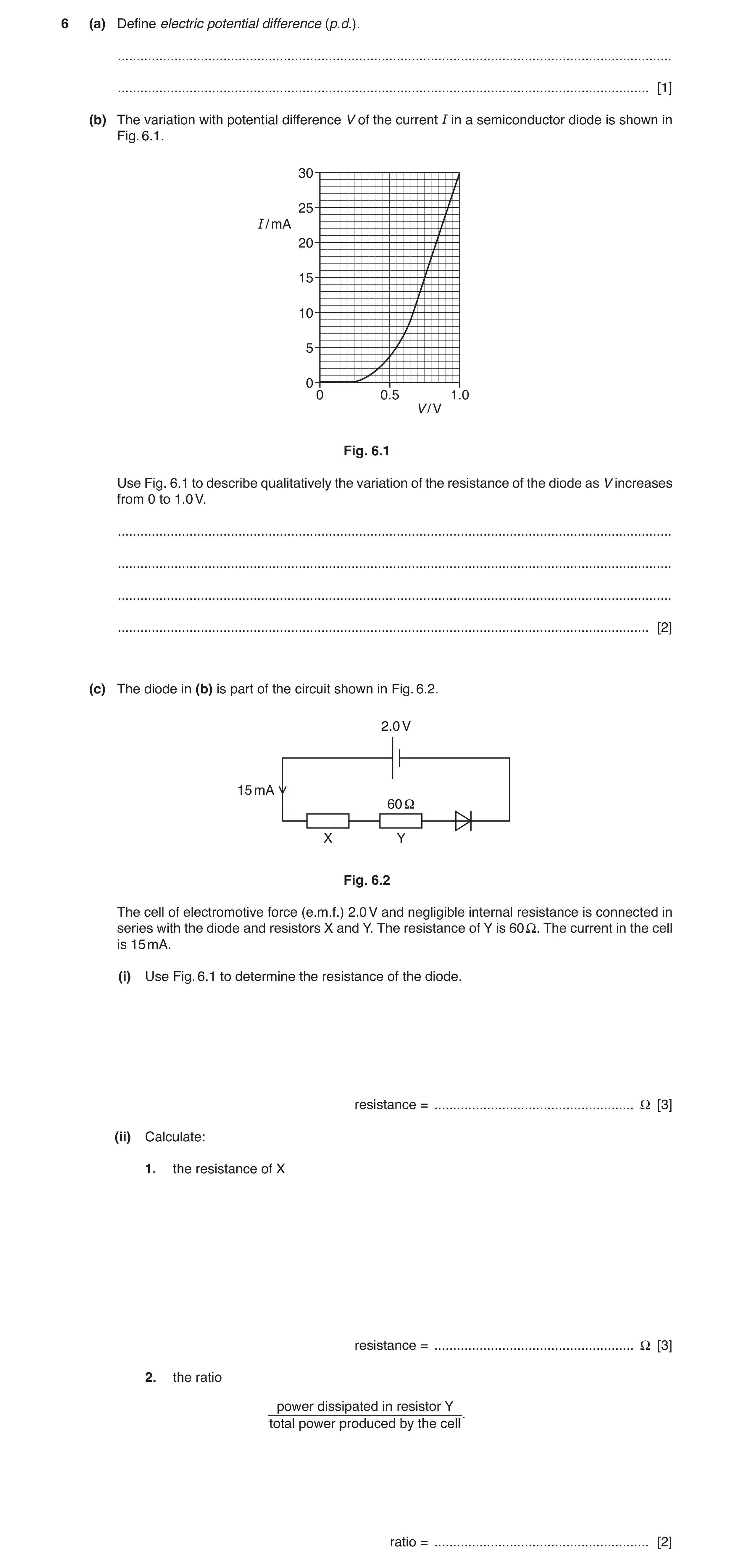
 30 / 40
 31 / 40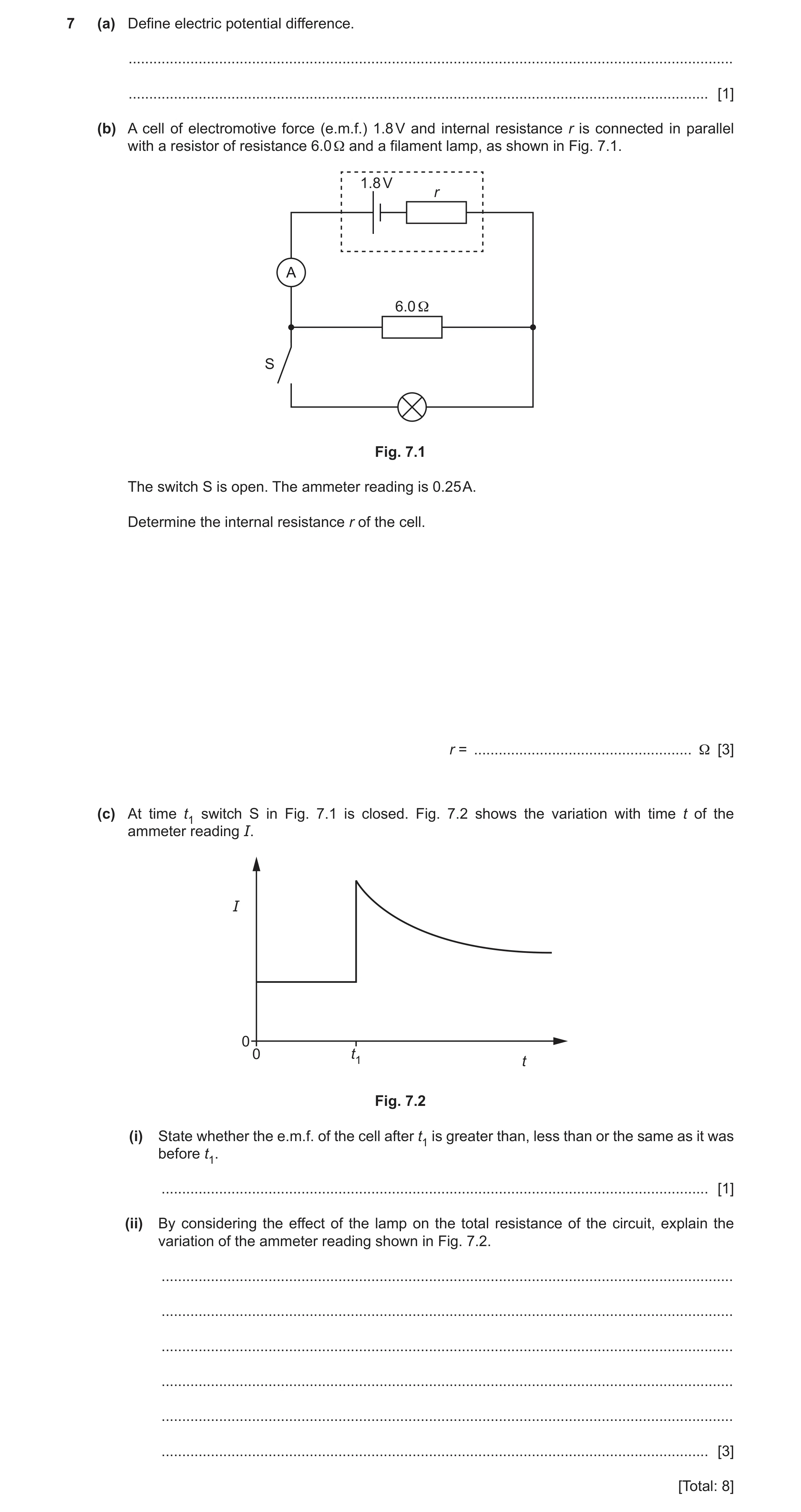
 10
10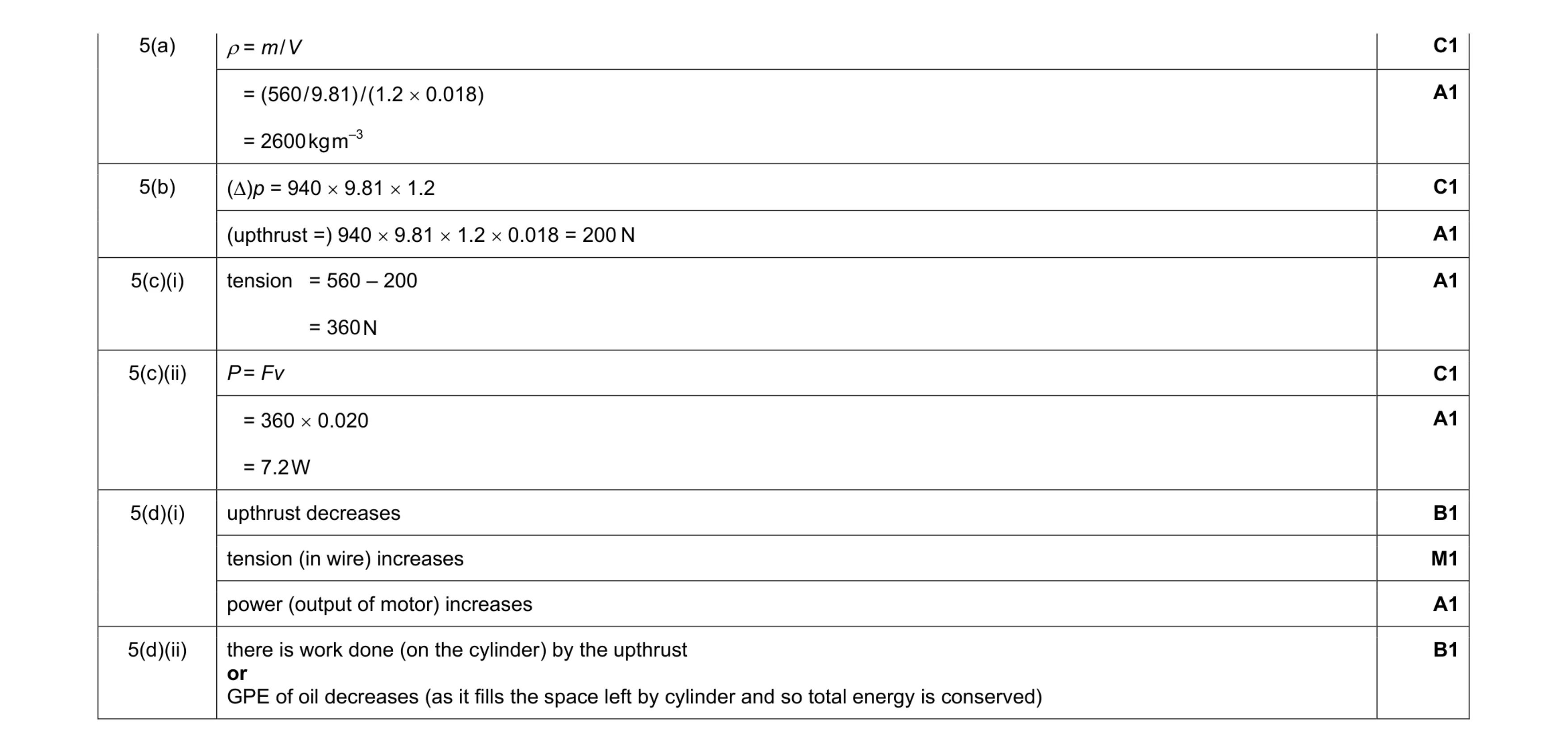 11
11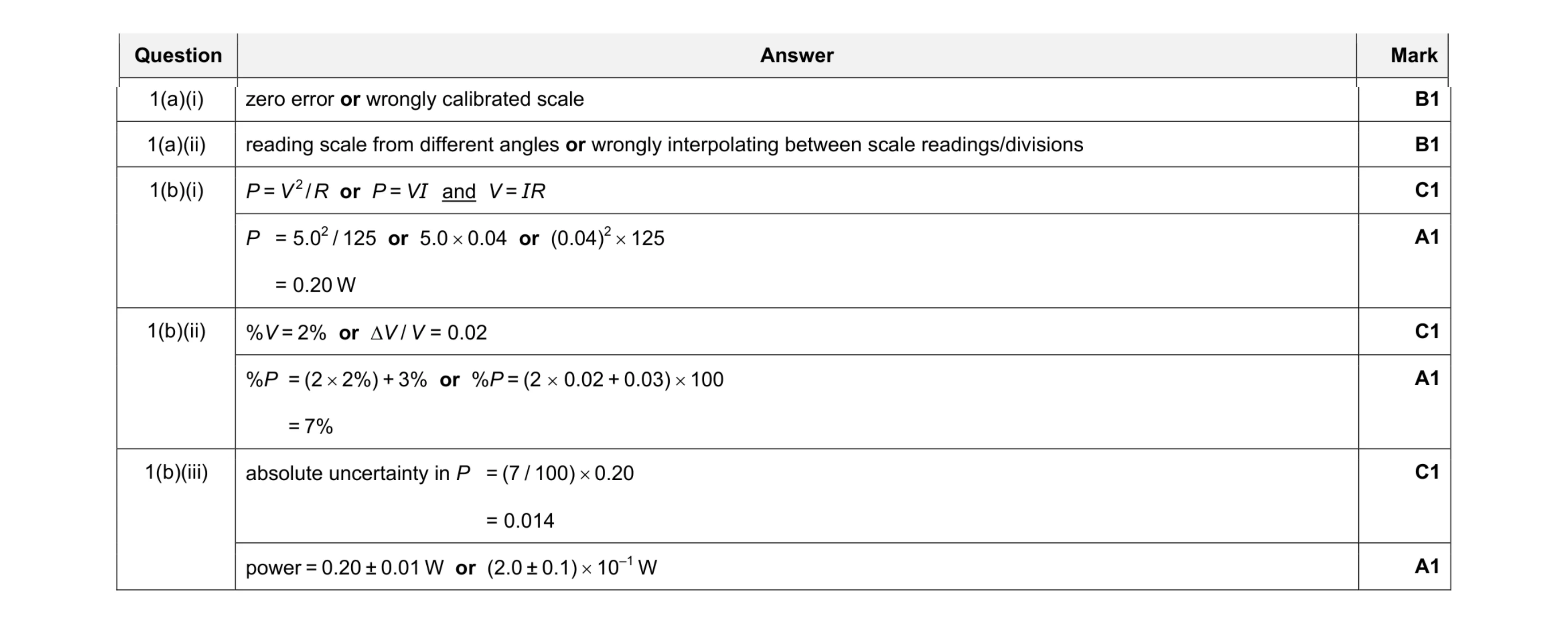 8
8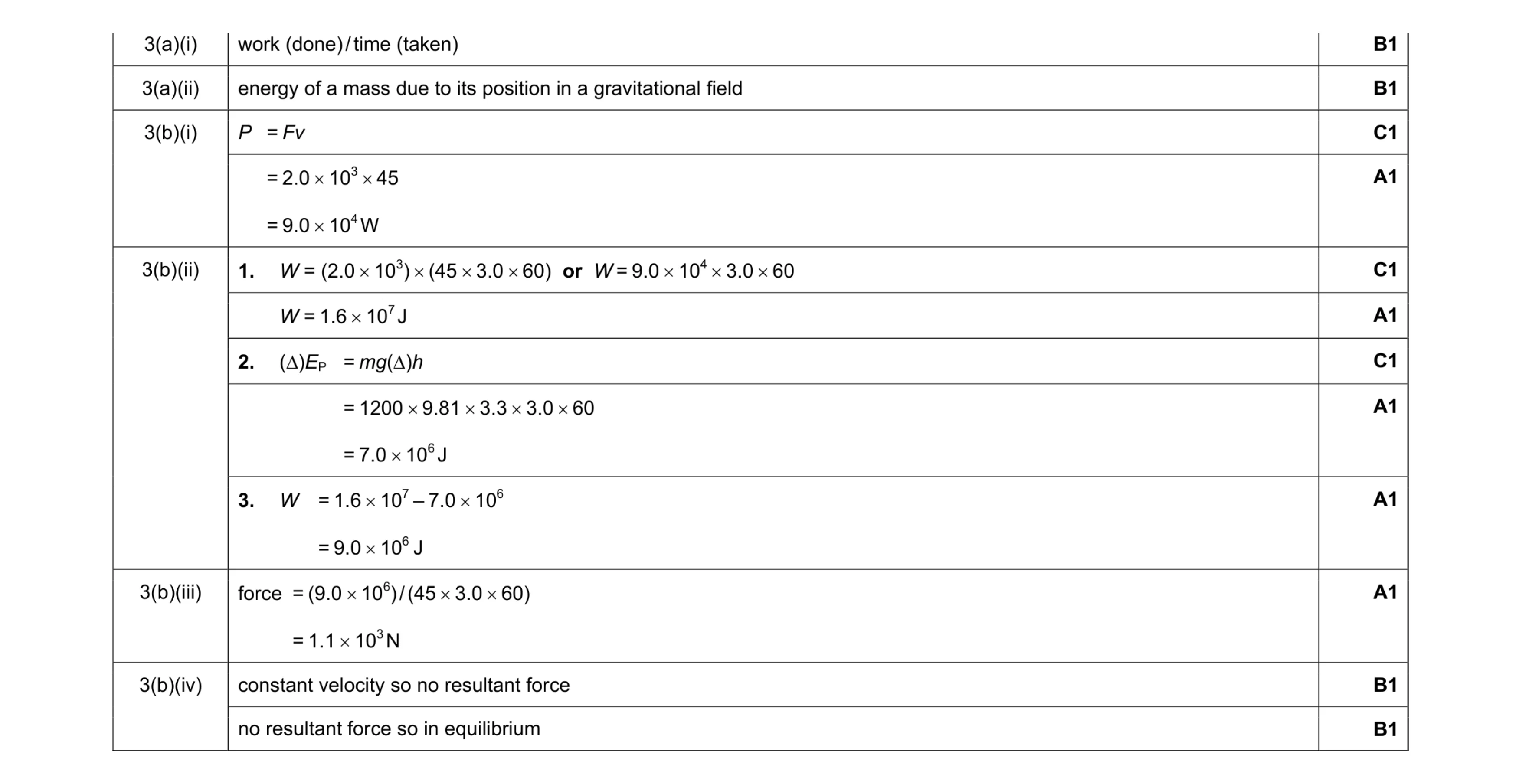 12
12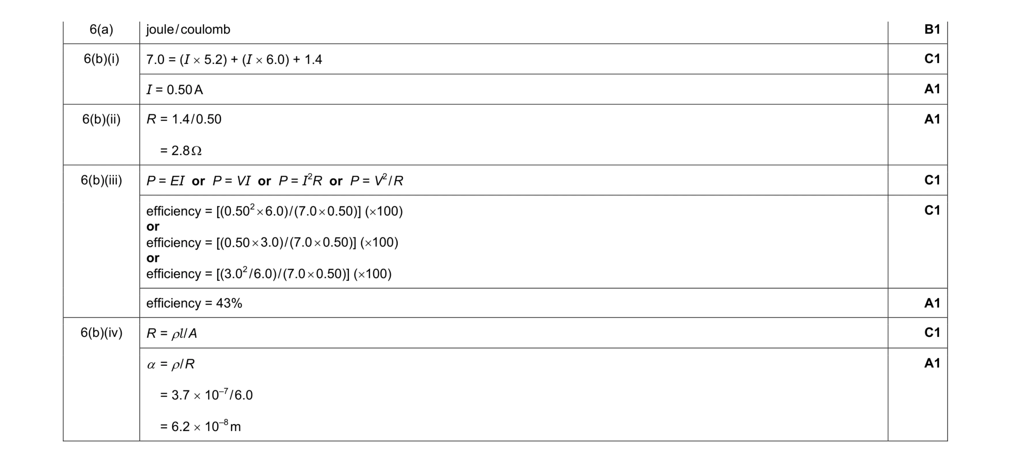 9
9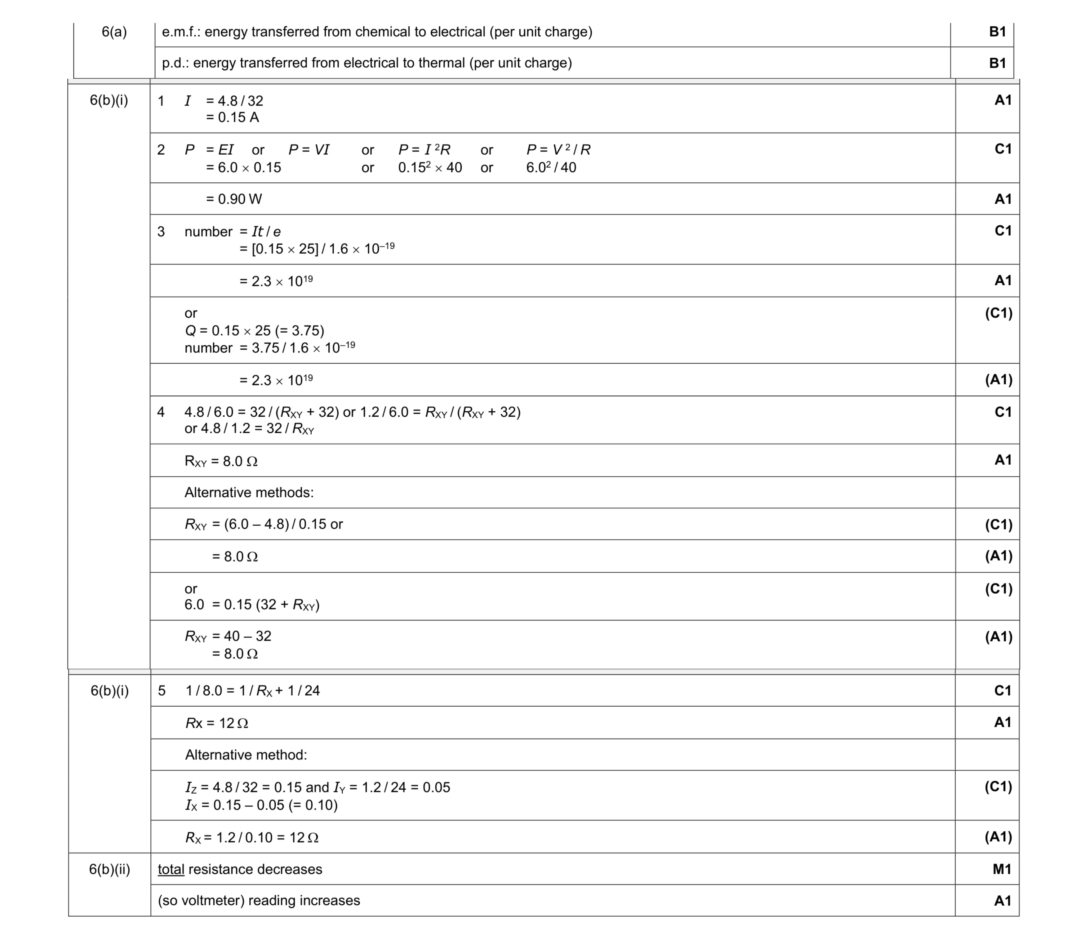 13
13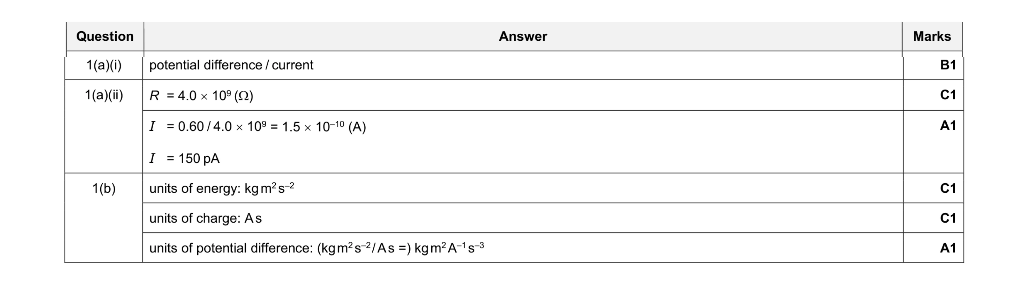 6
6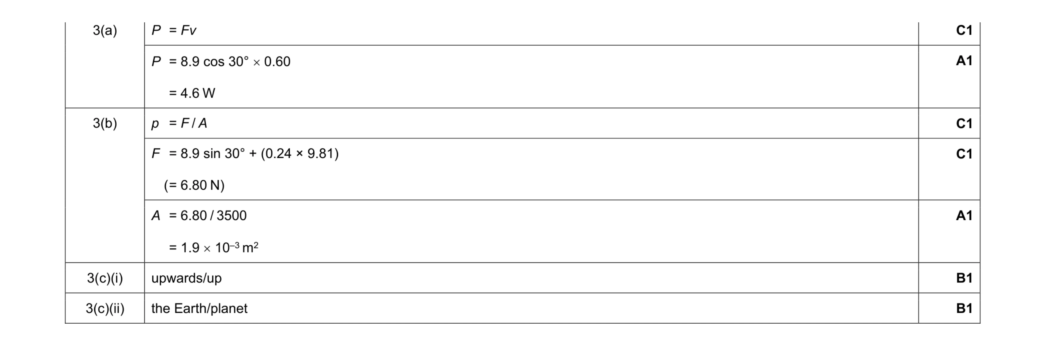 7
7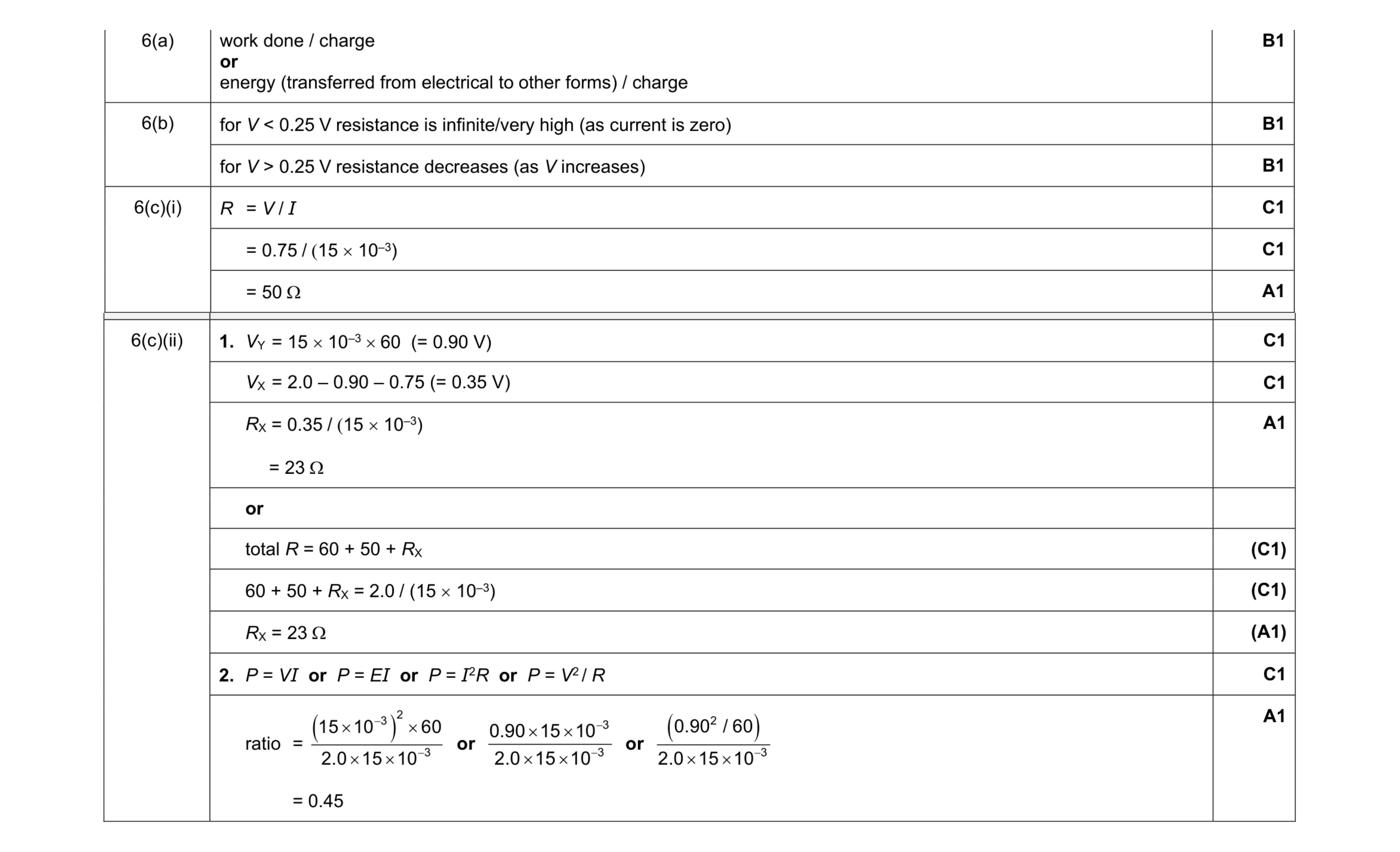 11
11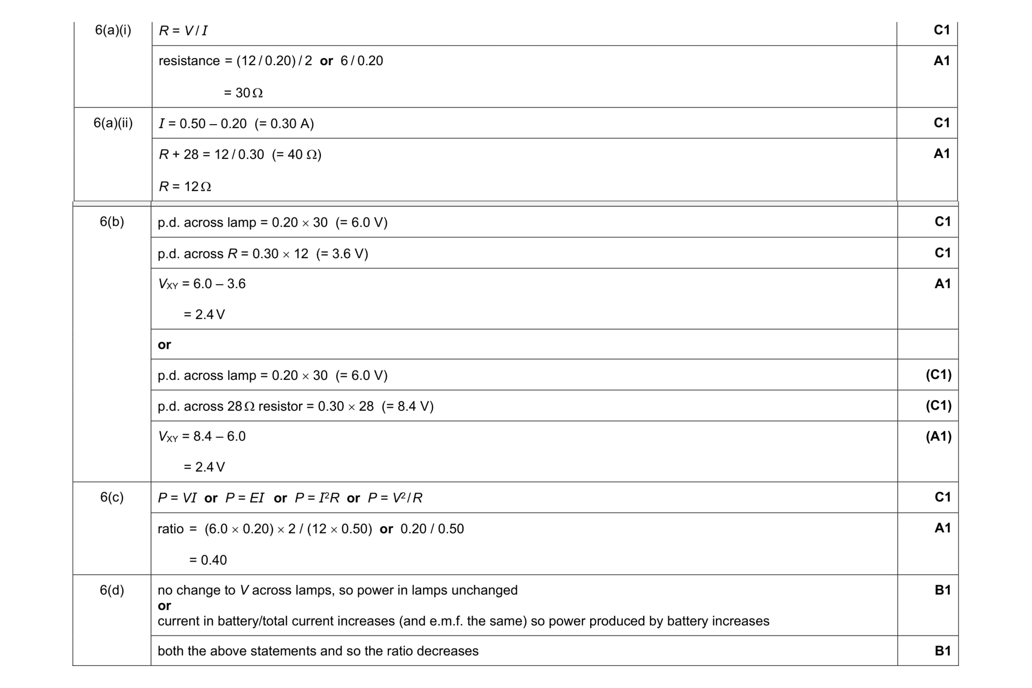 11
11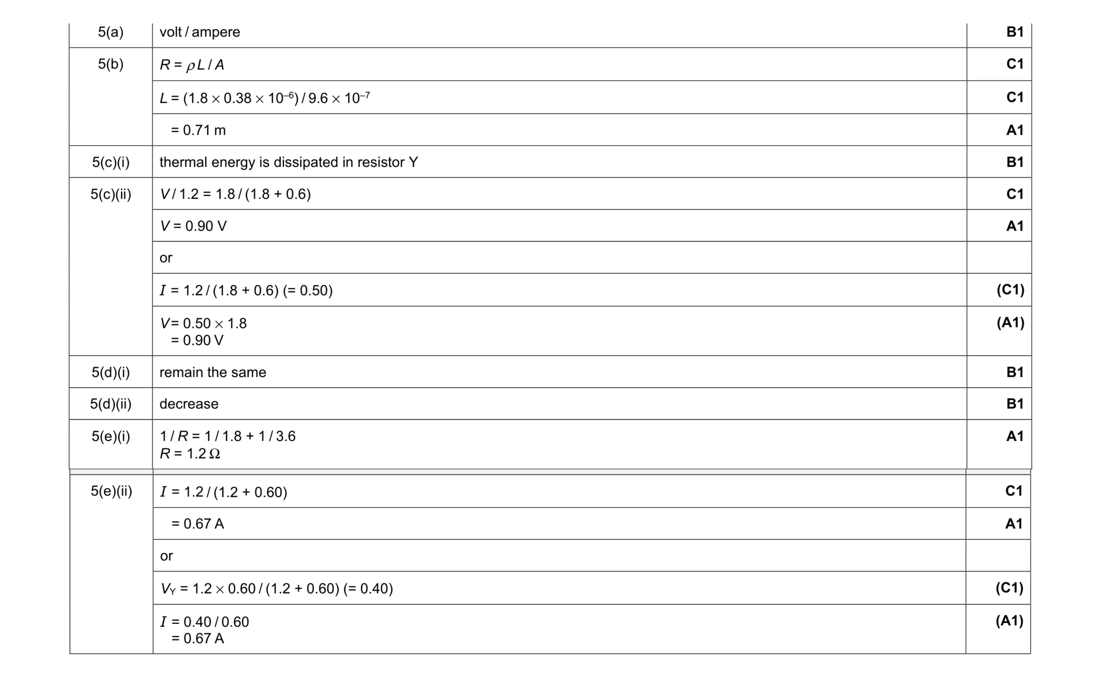 12
12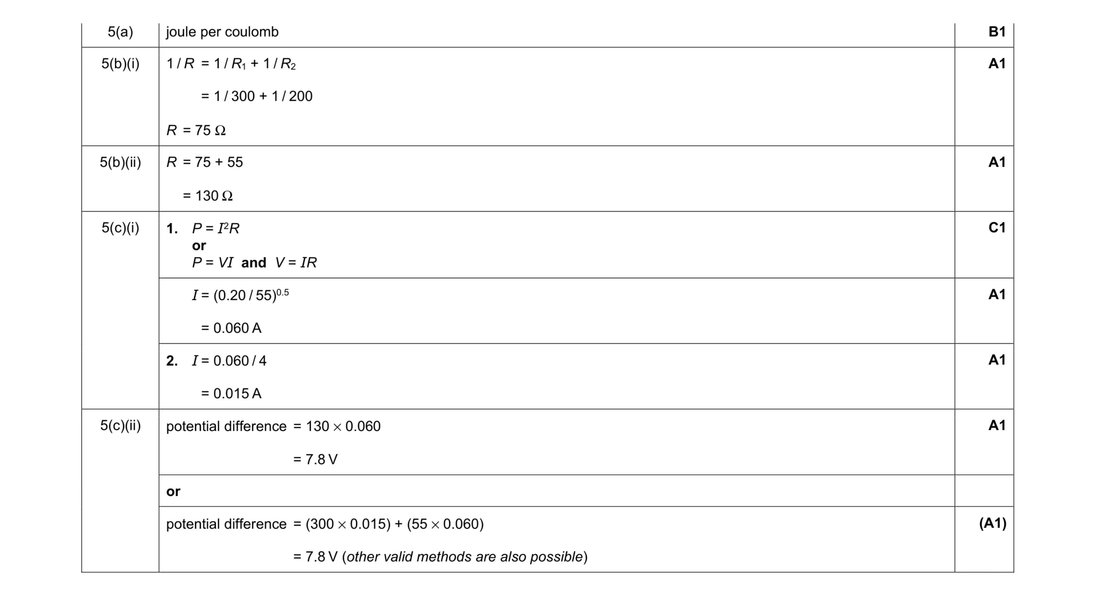 7
7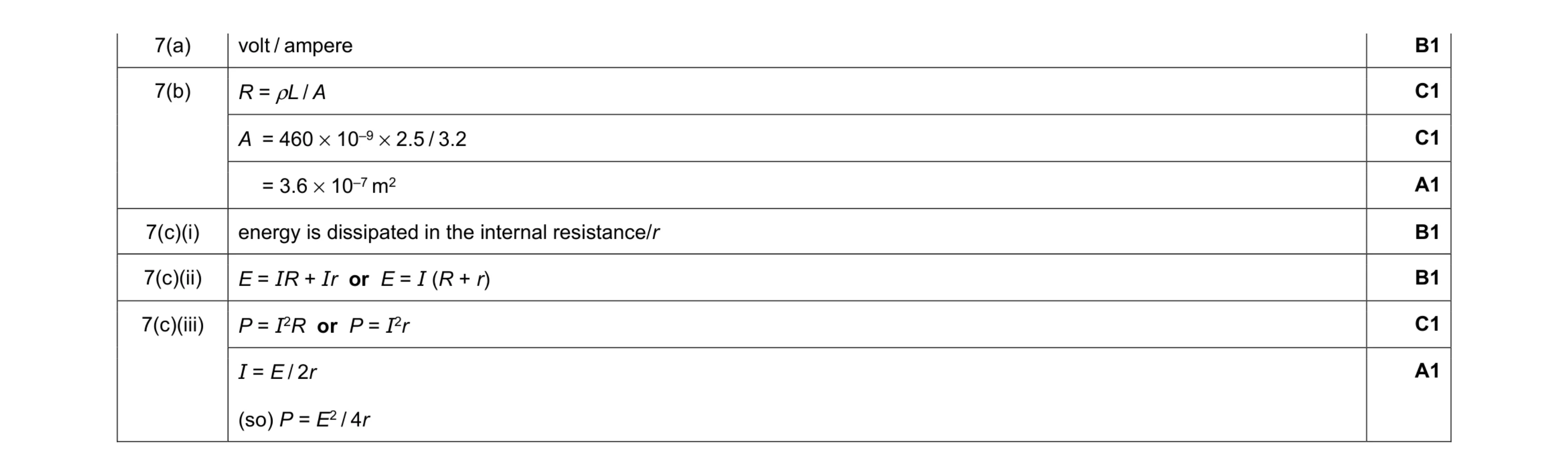 8
8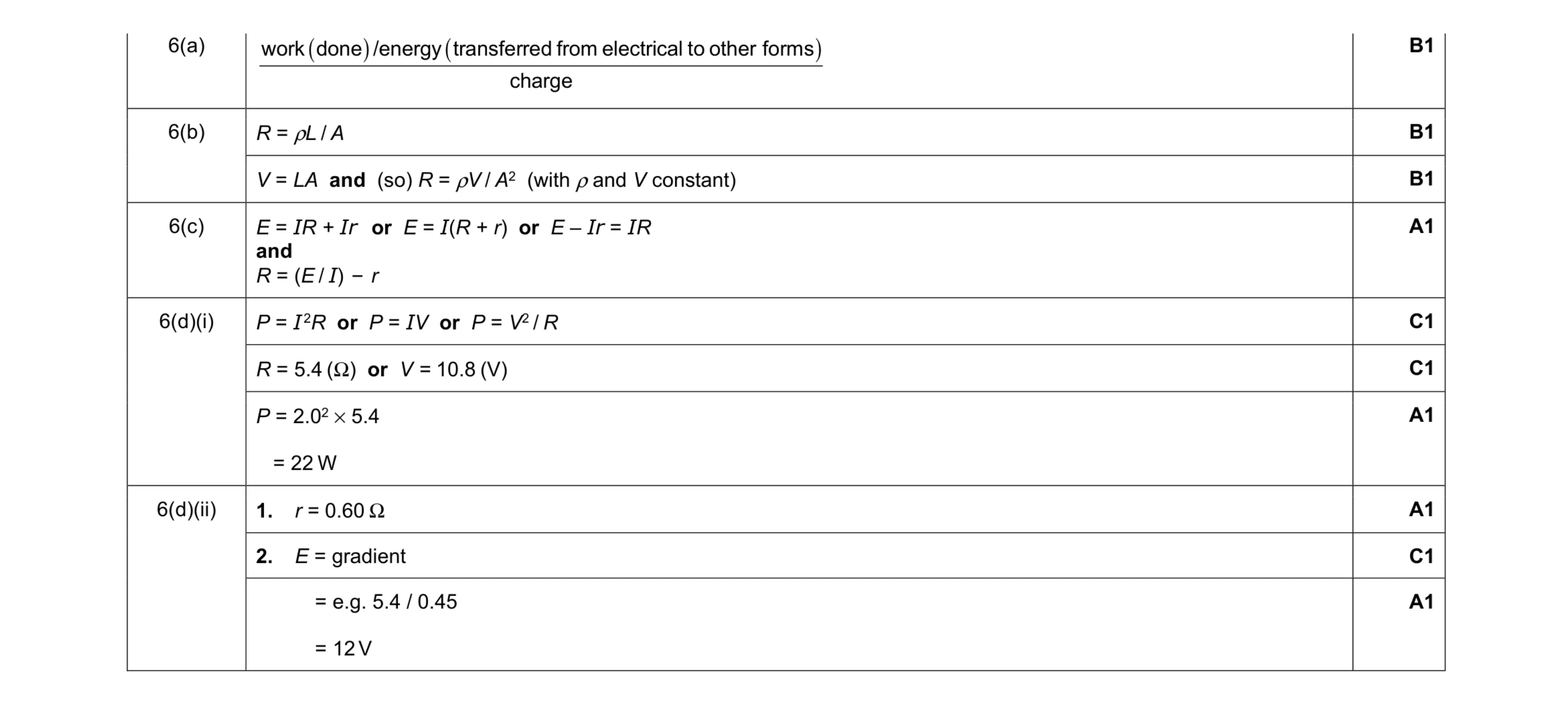 10
10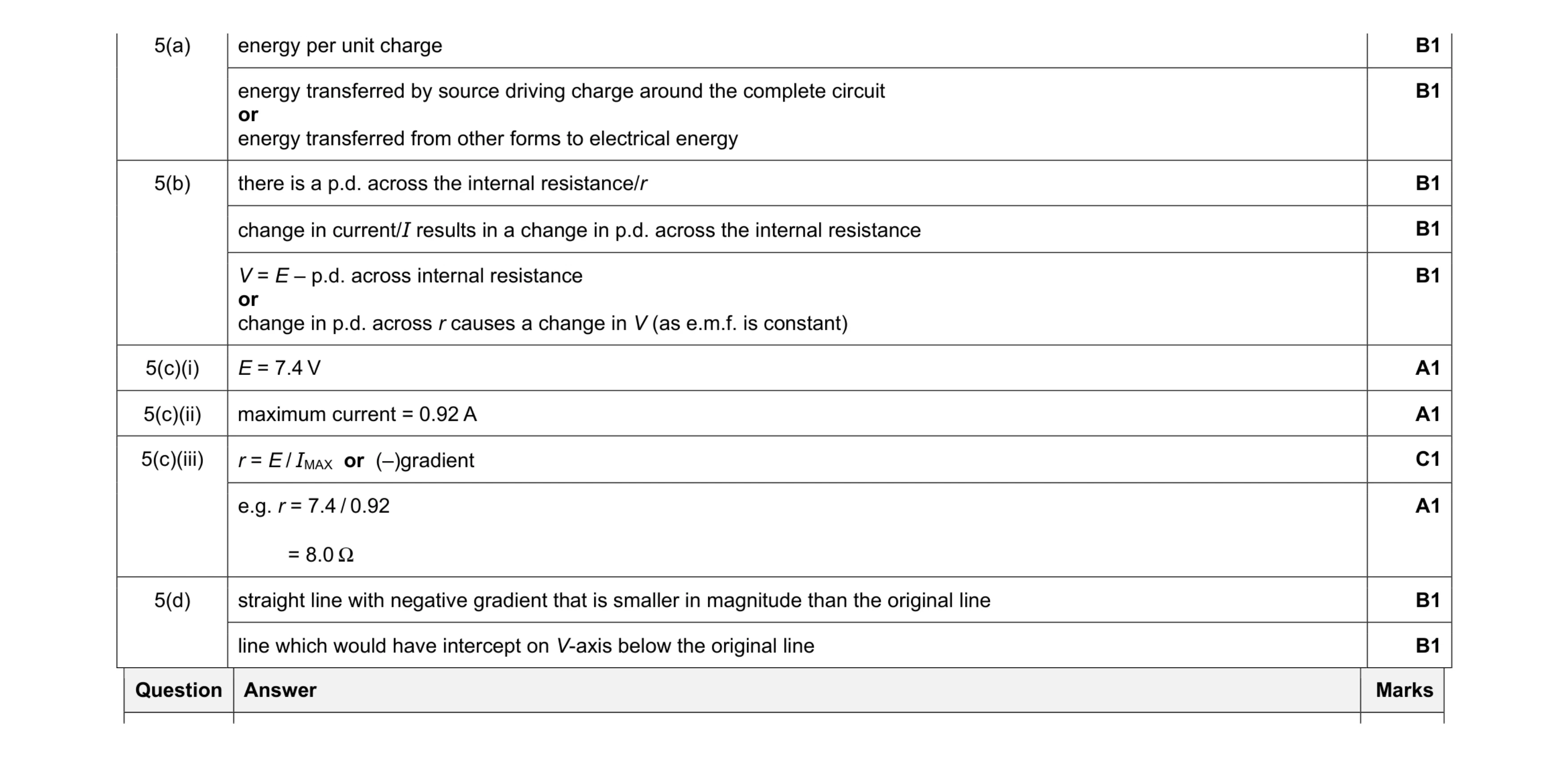 11
11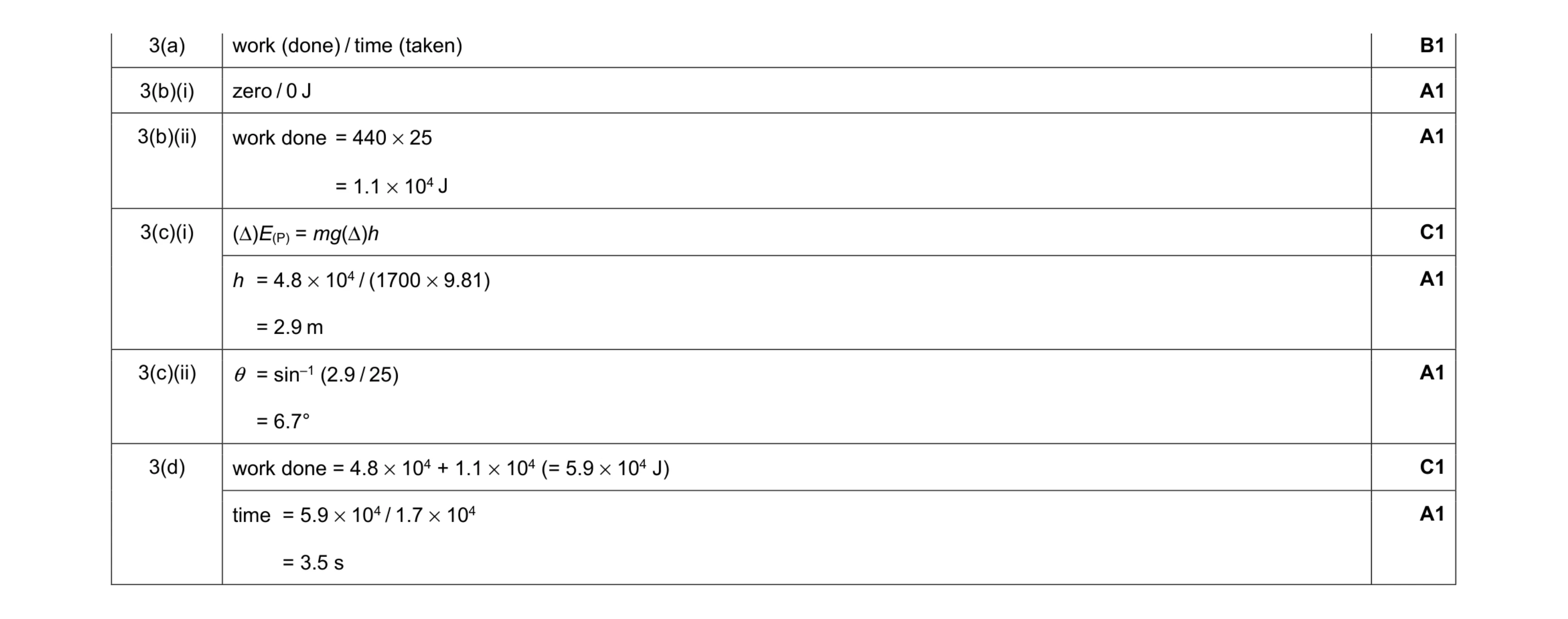 8
8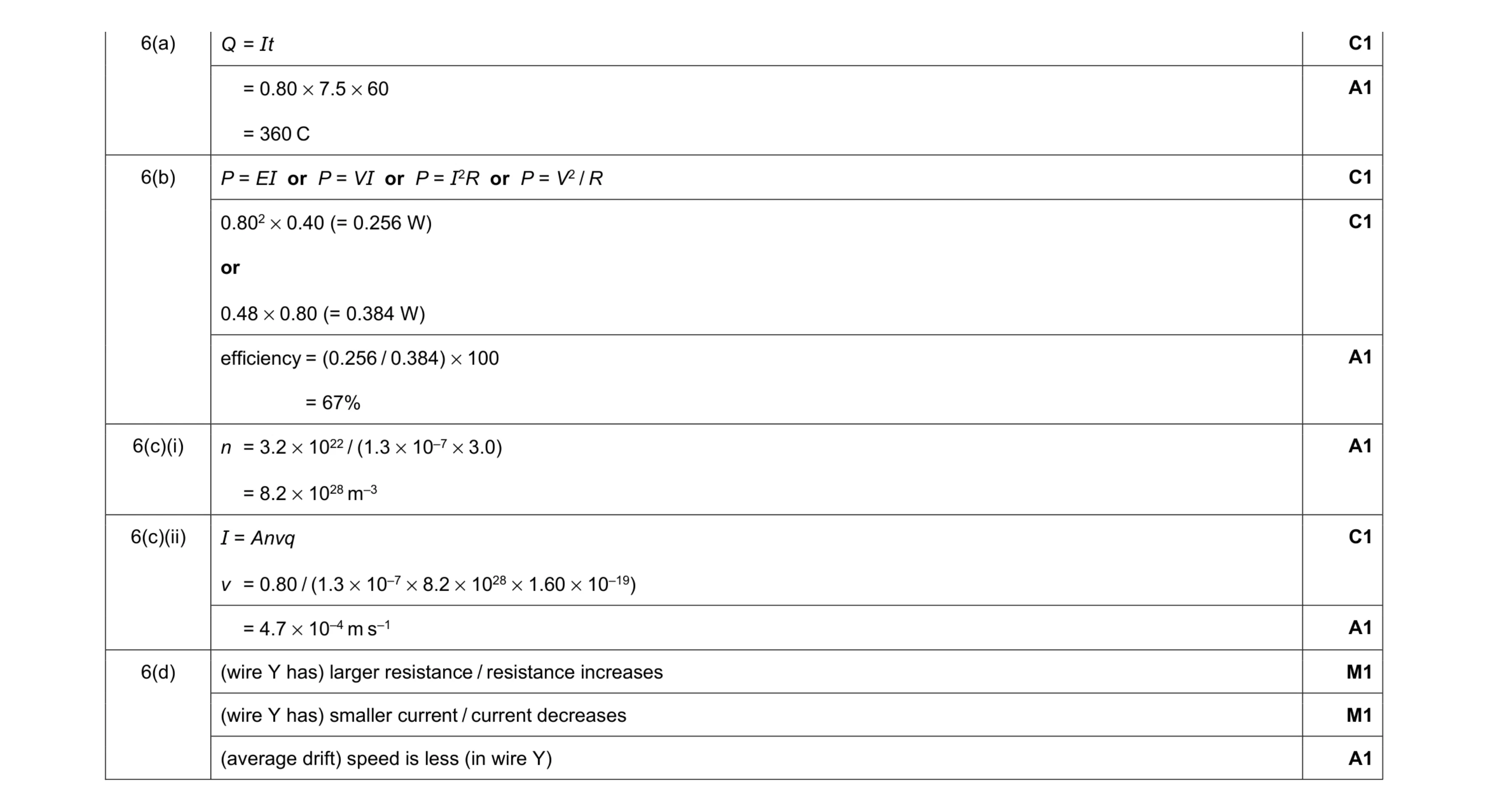 11
11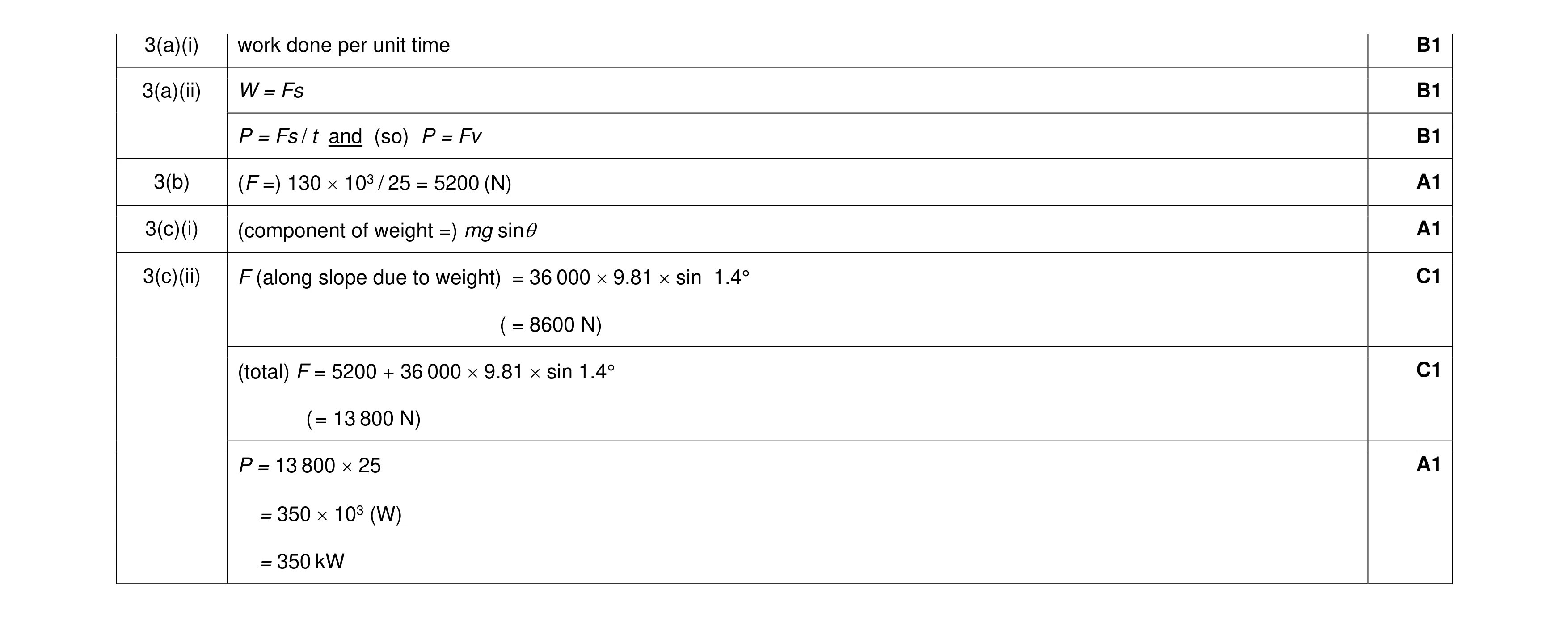 8
8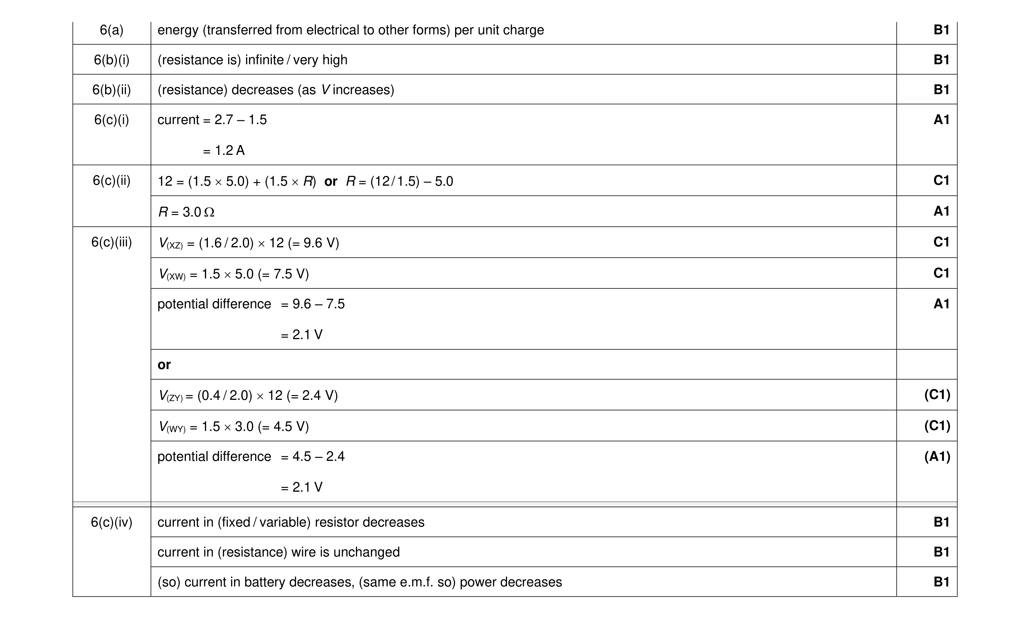 12
12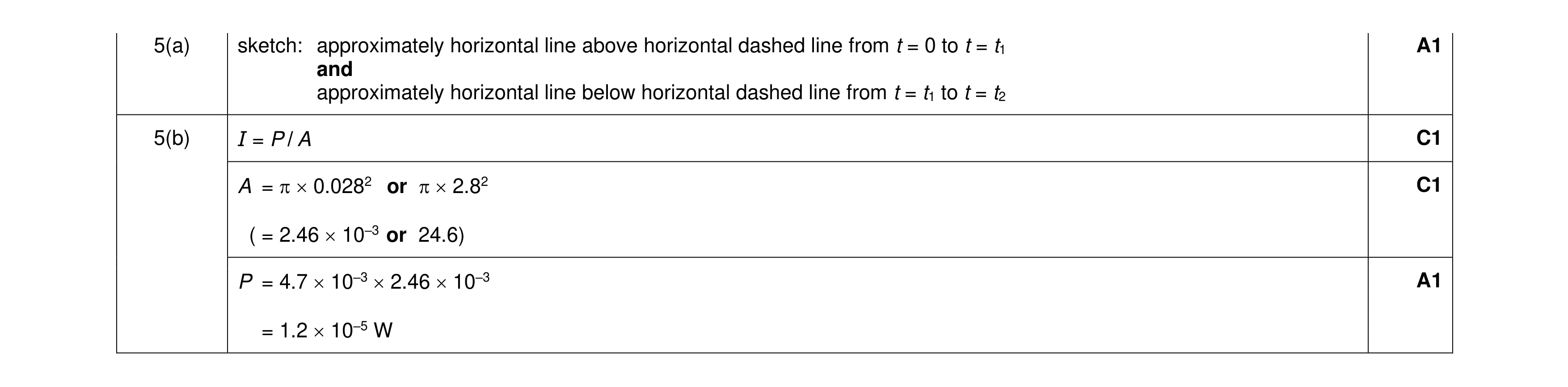 4
4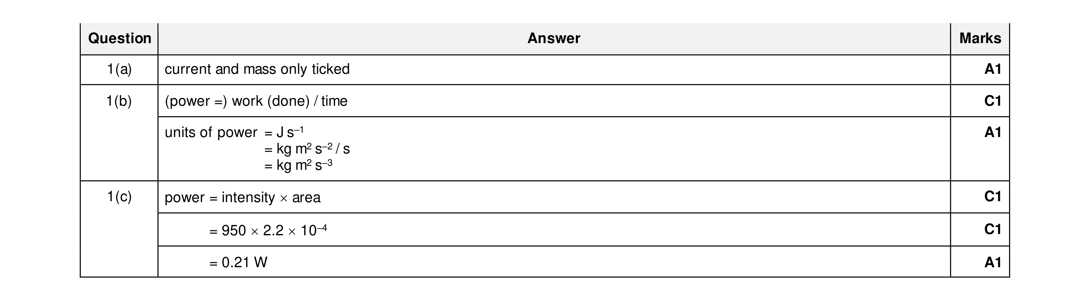 6
6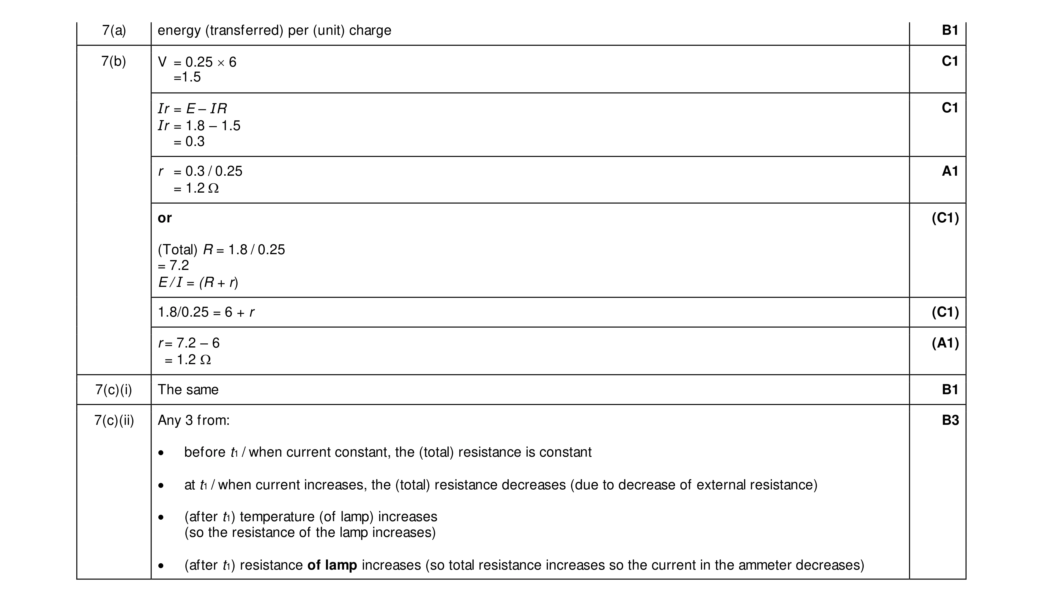 8
8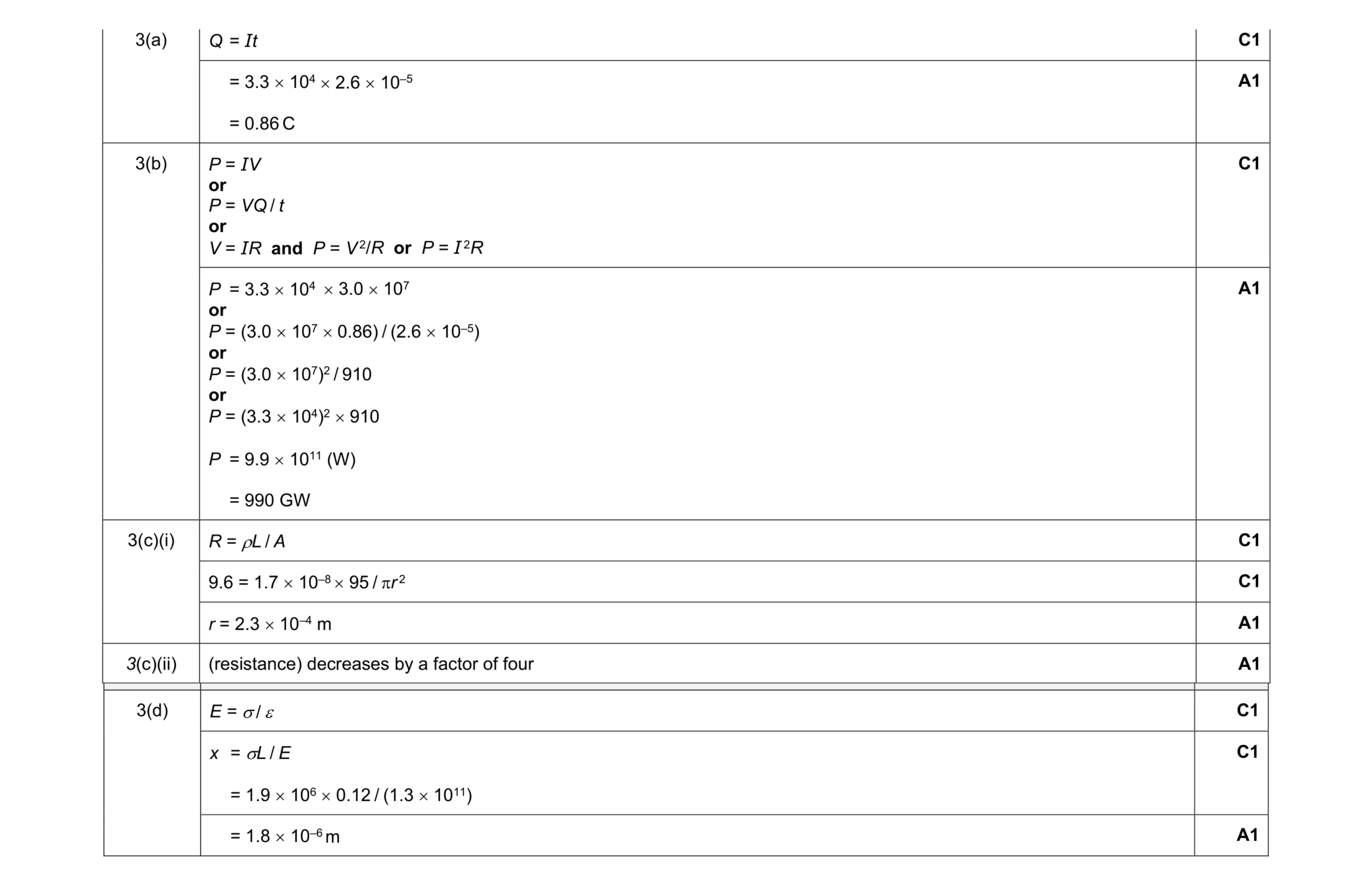 11
11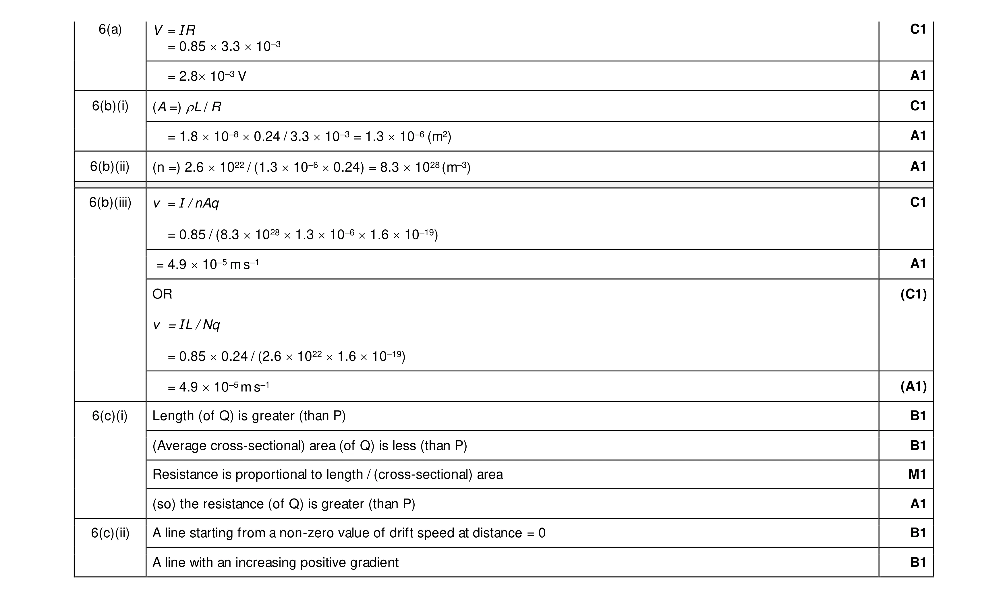 13
13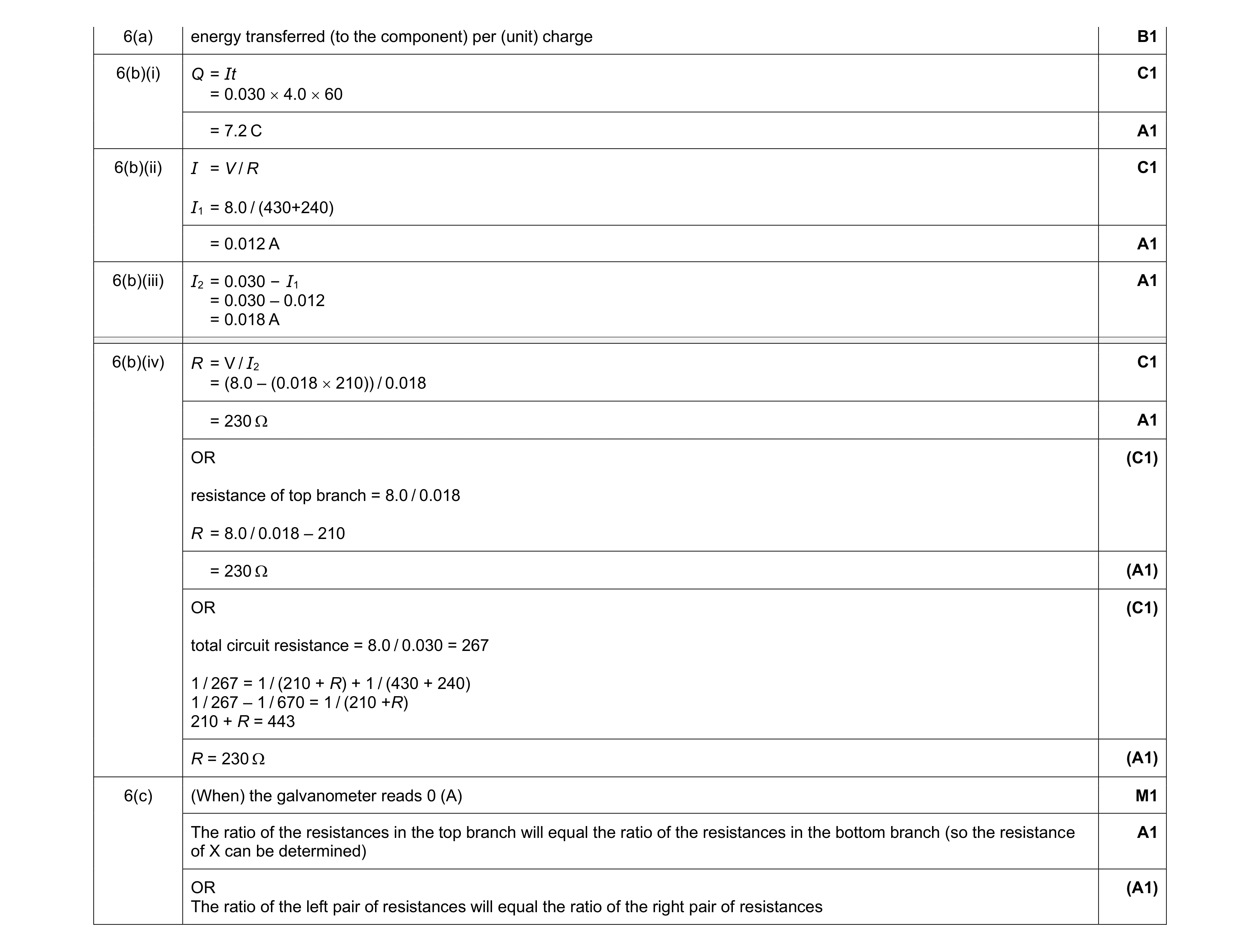 10
10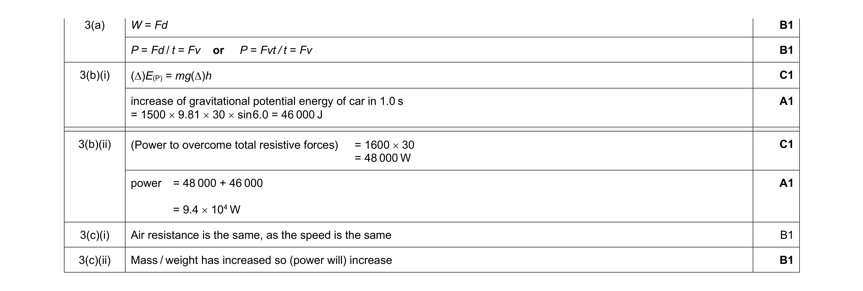 8
8