Questions as text
Q1 · The mean value of an alternating current is zero 9702/41 Oct/Nov 2017
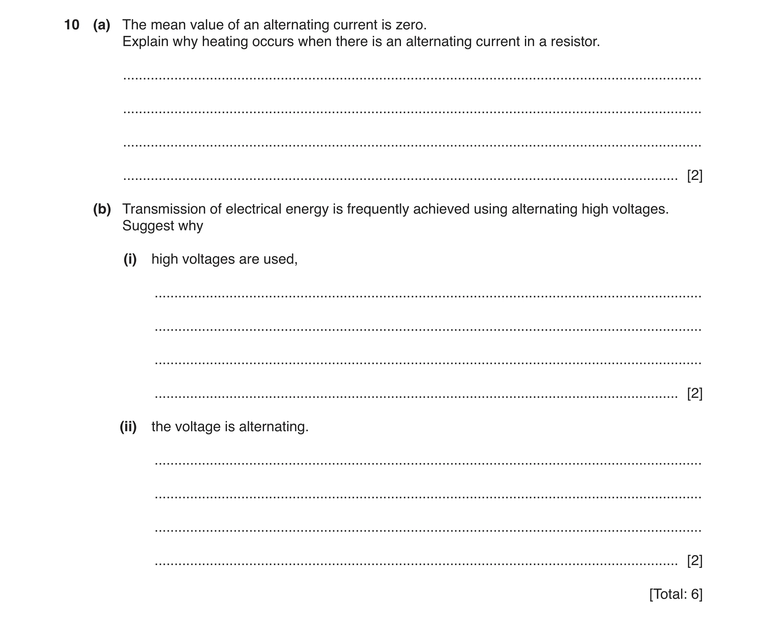
10 (a) The mean value of an alternating current is zero. Explain why heating occurs when there is an alternating current in a resistor. … … … … [2] (b) Transmission of electrical energy is frequently achieved using alternating high voltages. Suggest why (i) high voltages are used, … … … … [2] (ii) the voltage is alternating. … … … … [2] [Total: 6]
6 marks
Mark scheme: 10(a) B1 and current2/I2 is always positive B1 or a.c. changes direction (every half cycle) (B1) but heating effect is independent of current direction (B1) or voltage and current are always in phase in a resistor (B1) so V × I is always positive (B1) or sketch graph drawn showing power against time (B1) comment that power is always positive (B1) 10(b)(i) for same power (transmission, higher voltage) → lower current B1 lower current → less power loss in (transmission) cables B1 10(b)(ii) • voltage can be (easily) stepped up/down • transformers only work with a.c. • generators produce a.c. • easier to rectify than invert Two sensible suggestions, 1 mark each. B2
This question in 9702/41 Oct/Nov 2017
Q2 · The circuit for a full-wave rectifier using four ideal diodes is shown in Fig 9702/42 Oct/Nov 2017
11 The circuit for a full-wave rectifier using four ideal diodes is shown in Fig. 11.1. X A input Y R B Fig. 11.1 A resistor R is connected across the output AB of the rectifier. (a) On Fig. 11.1, (i) draw a circle around any diodes that conduct when the terminal X of the input is positive with respect to terminal Y, [1] (ii) label the positive (+) and the negative (–) terminals of the output AB. [1] (b) The variation with time t of the potential difference V across the input XY is given by the expression V = 5.6 sin 380t where V is measured in volts and t is measured in seconds. The variation with time t of the rectified potential difference across the resistor R is shown in Fig. 11.2. 6 rectified potential difference / V 4 2 0 t1 t2 t Fig. 11.2 Use the expression for the input potential difference V, or otherwise, to determine (i) the root-mean-square (r.m.s.) potential difference Vr.m.s. of the input, Vr.m.s. = … V [1] (ii) the number of times per second that the rectified potential difference at the output reaches a peak value. number = … [2] (c) A capacitor is now connected between the terminals AB of the output. The capacitor reduces the variation (the ripple) in the output to 1.6 V. (i) On Fig. 11.2, sketch the variation with time t of the smoothed output voltage for time t = t1 to time t = t2. [4] (ii) Suggest and explain the effect, if any, on the mean power dissipation in resistor R when the capacitor is connected between terminals AB. … … … [2] [Total: 11]
11 marks
Mark scheme: 11(a)(i) circles drawn only around the top left and bottom right diodes B1 11(a)(ii) B shown as (+)ve and A shown as (–)ve B1 11(b)(i) Vr.m.s. (= 5.6 / √2) = 4.0 V A1 11(b)(ii) 380 = 2πf or f = 60.5 Hz C1 number (= 2f ) = 120 A1 11(c)(i) peak values (all) unchanged B1 (all) minima shown at 4.0 V B1 three lines from near peak showing concave curves after leaving dotted line not ‘kinked’ and not cutting the peak reaching candidate’s minimum at the point where the decay meets the next dotted line B1 three lines drawn along the dotted lines showing rise in voltage from minima back to peak values B1 11(c)(ii) mean p.d. is higher or r.m.s. p.d. is higher or capacitor supplies energy to resistor M1 so (mean) power increases A1
This question in 9702/42 Oct/Nov 2017
Q3 · The mean value of an alternating current is zero 9702/43 Oct/Nov 2017
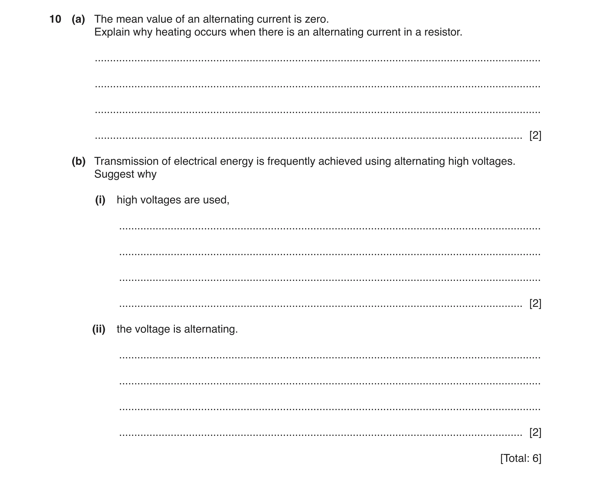
10 (a) The mean value of an alternating current is zero. Explain why heating occurs when there is an alternating current in a resistor. … … … … [2] (b) Transmission of electrical energy is frequently achieved using alternating high voltages. Suggest why (i) high voltages are used, … … … … [2] (ii) the voltage is alternating. … … … … [2] [Total: 6]
6 marks
Mark scheme: 10(a) B1 and current2/I2 is always positive B1 or a.c. changes direction (every half cycle) (B1) but heating effect is independent of current direction (B1) or voltage and current are always in phase in a resistor (B1) so V × I is always positive (B1) or sketch graph drawn showing power against time (B1) comment that power is always positive (B1) 10(b)(i) for same power (transmission, higher voltage) → lower current B1 lower current → less power loss in (transmission) cables B1 10(b)(ii) • voltage can be (easily) stepped up/down • transformers only work with a.c. • generators produce a.c. • easier to rectify than invert Two sensible suggestions, 1 mark each. B2
This question in 9702/43 Oct/Nov 2017
Q4 · A mass is undergoing simple harmonic motion with amplitude x0 9702/42 Feb/March 2018
3 (a) A mass is undergoing simple harmonic motion with amplitude x0. The maximum velocity of the mass has magnitude v0. On Fig. 3.1, show the variation with displacement x of the velocity v of the mass. v v0 0 −x0 0 x0 x −v0 Fig. 3.1 [2] (b) A straight stiff wire carries a constant current in a region of uniform magnetic flux density. The angle θ between the direction of the current and the direction of the magnetic field is varied. The maximum force on the wire is F0. On Fig. 3.2, show the variation with angle θ of the force F on the wire for values of θ between 0° and 90°. F0 F 0 0 90 θ/° Fig. 3.2 [2] (c) A sinusoidal supply has frequency 250 Hz and r.m.s. potential difference 2.8 V. On the axes of Fig. 3.3, show quantitatively the variation with time t of the voltage V for one cycle of the varying voltage. 8 V / V 6 4 2 00 1 2 3 4 5 t / ms −2 −4 −6 −8 Fig. 3.3 [2] (d) One particular fission reaction may be represented by the equation 23 9 52U + 10n 14516Ba + 9326Kr + 310n The variation with nucleon number A of the binding energy per nucleon BE is shown in Fig. 3.4. BE 0 0 A Fig. 3.4 On Fig. 3.4, mark on the line the position of (i) the nucleus 23952U (label this point U), (ii) the nucleus 14516Ba (label this point Ba), (iii) the nucleus 9326Kr (label this point Kr). [2] [Total: 8]
8 marks
Mark scheme: 3(a) reasonably shaped circle or oval surrounding the origin B1 closed loop passing through (0,±v0) and (±x0,0) B1 3(b) line from (0,0) to (90, F0) B1 curve with decreasing positive gradient, zero gradient at θ = 90 B1 3(c) reasonable sinusoidal wave, one cycle, period 4.0 ms B1 amplitude at 4.0 V B1 3(d) U near right-hand end of line with Ba between U and peak of graph B1 Ba on right hand side of peak and Kr between Ba and peak of graph B1
This question in 9702/42 Feb/March 2018
Q5 · A rigid copper wire is held horizontally between the pole pieces of two magnets, as shown… 9702/41 May/June 2018
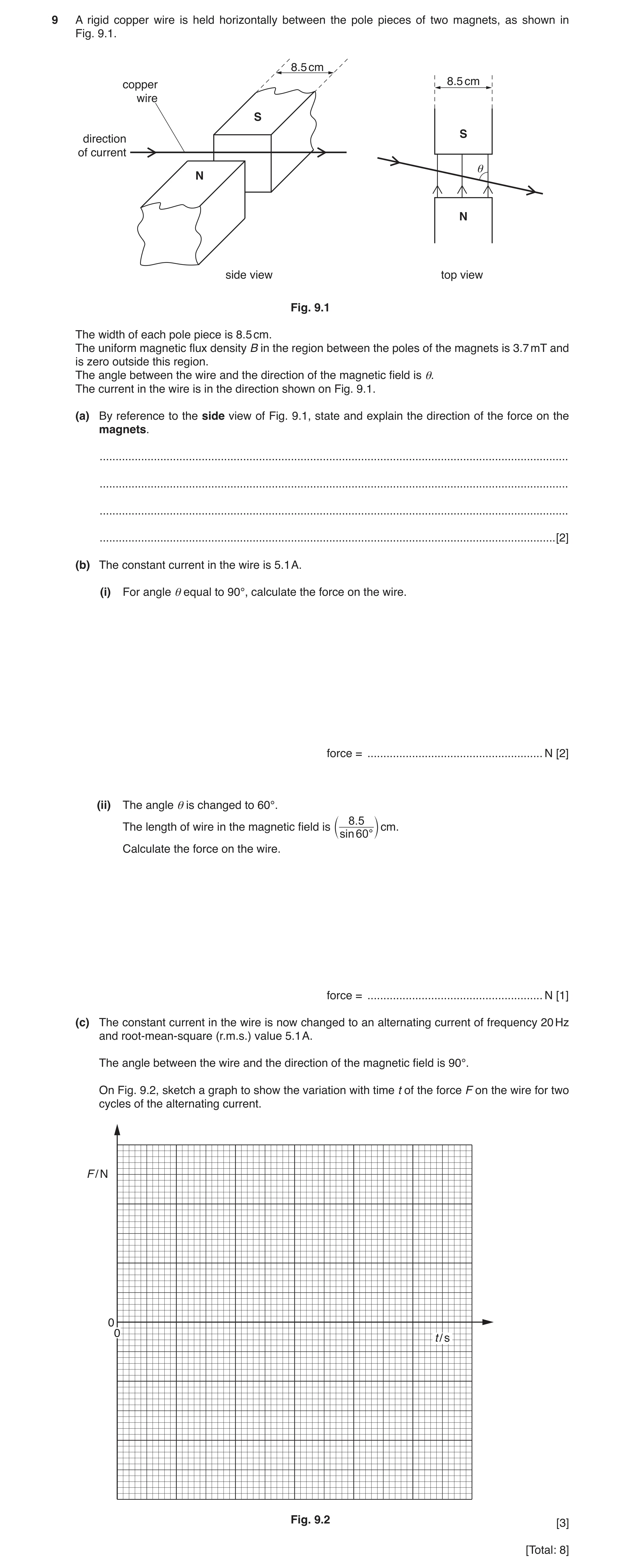
9 A rigid copper wire is held horizontally between the pole pieces of two magnets, as shown in Fig. 9.1. 8.5 cm 8.5 cm copper wire S S direction of current θ N N side view top view Fig. 9.1 The width of each pole piece is 8.5 cm. The uniform magnetic flux density B in the region between the poles of the magnets is 3.7 mT and is zero outside this region. The angle between the wire and the direction of the magnetic field is θ. The current in the wire is in the direction shown on Fig. 9.1. (a) By reference to the side view of Fig. 9.1, state and explain the direction of the force on the magnets. … … … … [2] (b) The constant current in the wire is 5.1 A. (i) For angle θ equal to 90°, calculate the force on the wire. force = … N [2] (ii) The angle θ is changed to 60°. 8 .5 The length of wire in the magnetic field is cm. c sin60 ° m Calculate the force on the wire. force = … N [1] (c) The constant current in the wire is now changed to an alternating current of frequency 20 Hz and root-mean-square (r.m.s.) value 5.1 A. The angle between the wire and the direction of the magnetic field is 90°. On Fig. 9.2, sketch a graph to show the variation with time t of the force F on the wire for two cycles of the alternating current. F / N 0 0 t / s Fig. 9.2 [3] [Total: 8]
8 marks
Mark scheme: 9(a) using Fleming’s left-hand rule force on wire is upwards B1 by Newton’s third law, force on magnet is downwards B1 9(b)(i) F = BIL C1 = 3.7 × 10–3 × 5.1 × 8.5 × 10–2 = 1.6 × 10⁻³ N A1 9(b)(ii) F = 1.6 × 10⁻³ N A1 9(c) sketch: sinusoidal wave with two cycles B1 amplitude 2.3 × 10⁻³ N B1 period 0.05 s B1
This question in 9702/41 May/June 2018
Q6 · A rigid copper wire is held horizontally between the pole pieces of two magnets, as shown… 9702/43 May/June 2018
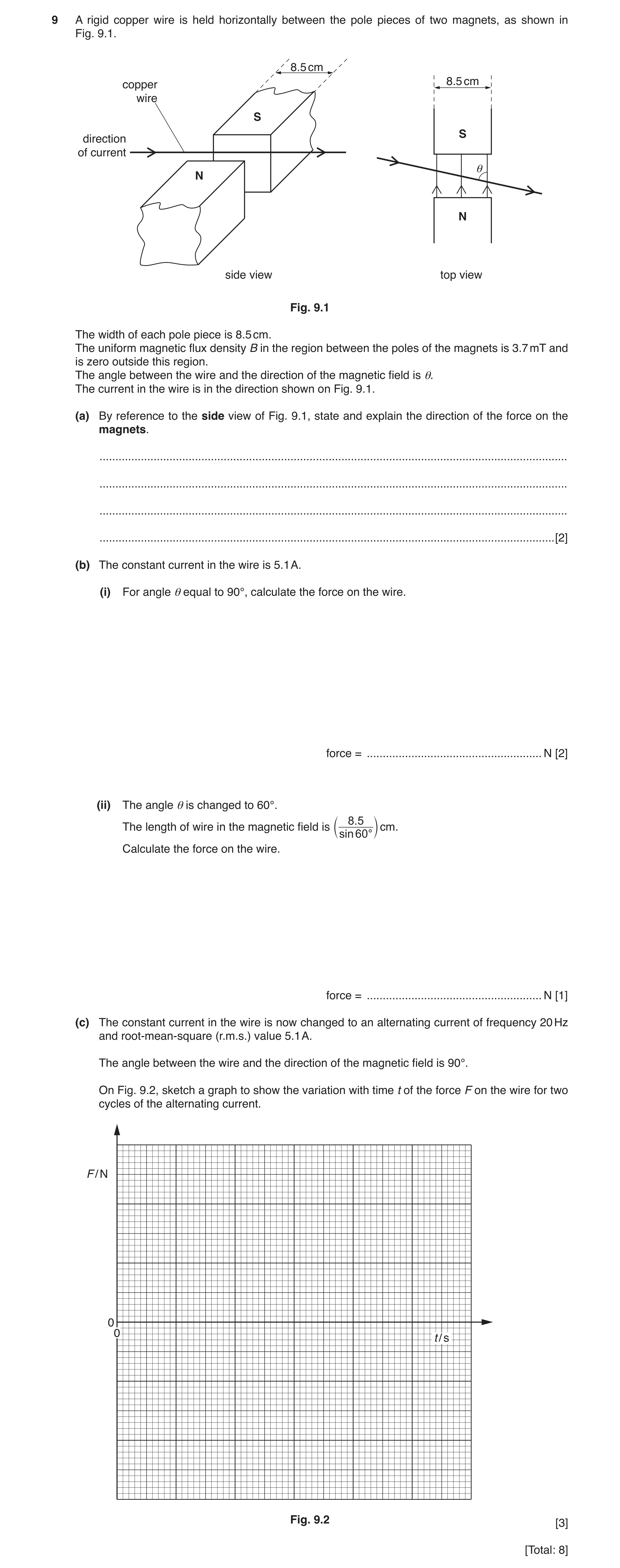
9 A rigid copper wire is held horizontally between the pole pieces of two magnets, as shown in Fig. 9.1. 8.5 cm 8.5 cm copper wire S S direction of current θ N N side view top view Fig. 9.1 The width of each pole piece is 8.5 cm. The uniform magnetic flux density B in the region between the poles of the magnets is 3.7 mT and is zero outside this region. The angle between the wire and the direction of the magnetic field is θ. The current in the wire is in the direction shown on Fig. 9.1. (a) By reference to the side view of Fig. 9.1, state and explain the direction of the force on the magnets. … … … … [2] (b) The constant current in the wire is 5.1 A. (i) For angle θ equal to 90°, calculate the force on the wire. force = … N [2] (ii) The angle θ is changed to 60°. 8 .5 The length of wire in the magnetic field is cm. c sin60 ° m Calculate the force on the wire. force = … N [1] (c) The constant current in the wire is now changed to an alternating current of frequency 20 Hz and root-mean-square (r.m.s.) value 5.1 A. The angle between the wire and the direction of the magnetic field is 90°. On Fig. 9.2, sketch a graph to show the variation with time t of the force F on the wire for two cycles of the alternating current. F / N 0 0 t / s Fig. 9.2 [3] [Total: 8]
8 marks
Mark scheme: 9(a) using Fleming’s left-hand rule force on wire is upwards B1 by Newton’s third law, force on magnet is downwards B1 9(b)(i) F = BIL C1 = 3.7 × 10–3 × 5.1 × 8.5 × 10–2 = 1.6 × 10⁻³ N A1 9(b)(ii) F = 1.6 × 10⁻³ N A1 9(c) sketch: sinusoidal wave with two cycles B1 amplitude 2.3 × 10⁻³ N B1 period 0.05 s B1
This question in 9702/43 May/June 2018
Q7 · State two advantages of the transmission of data in digital form, compared with the… 9702/41 Oct/Nov 2018
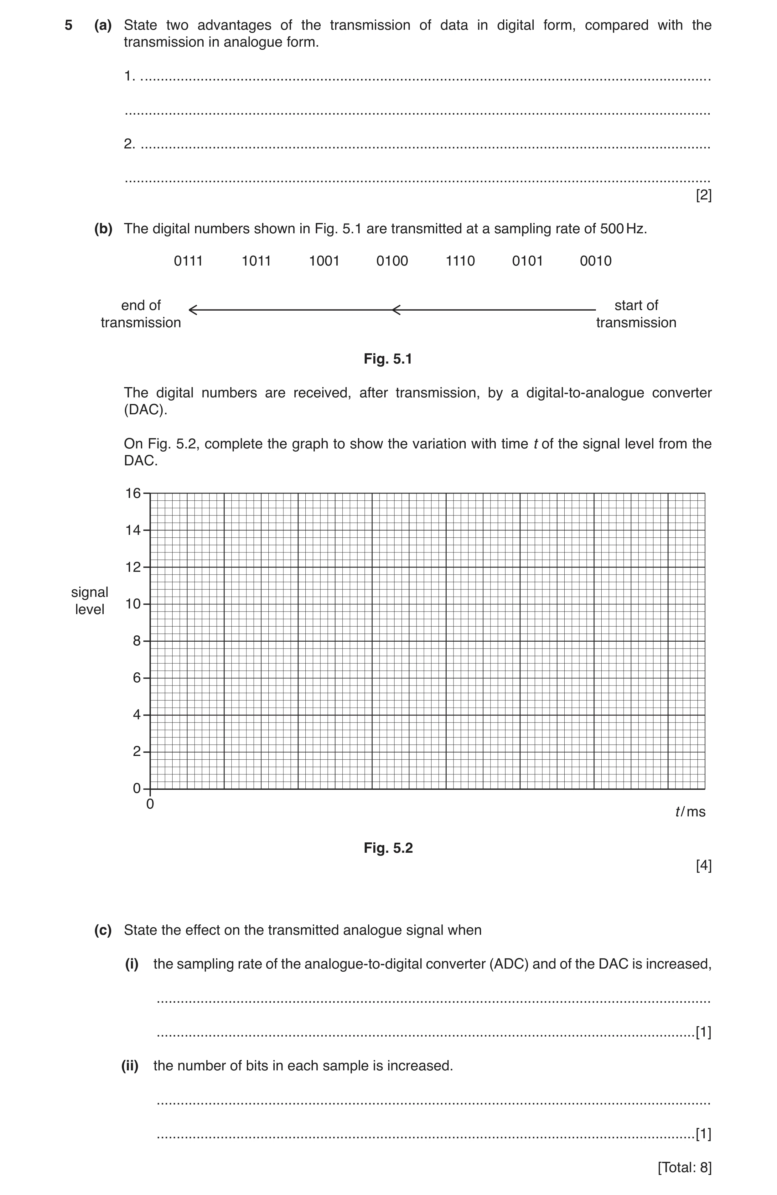
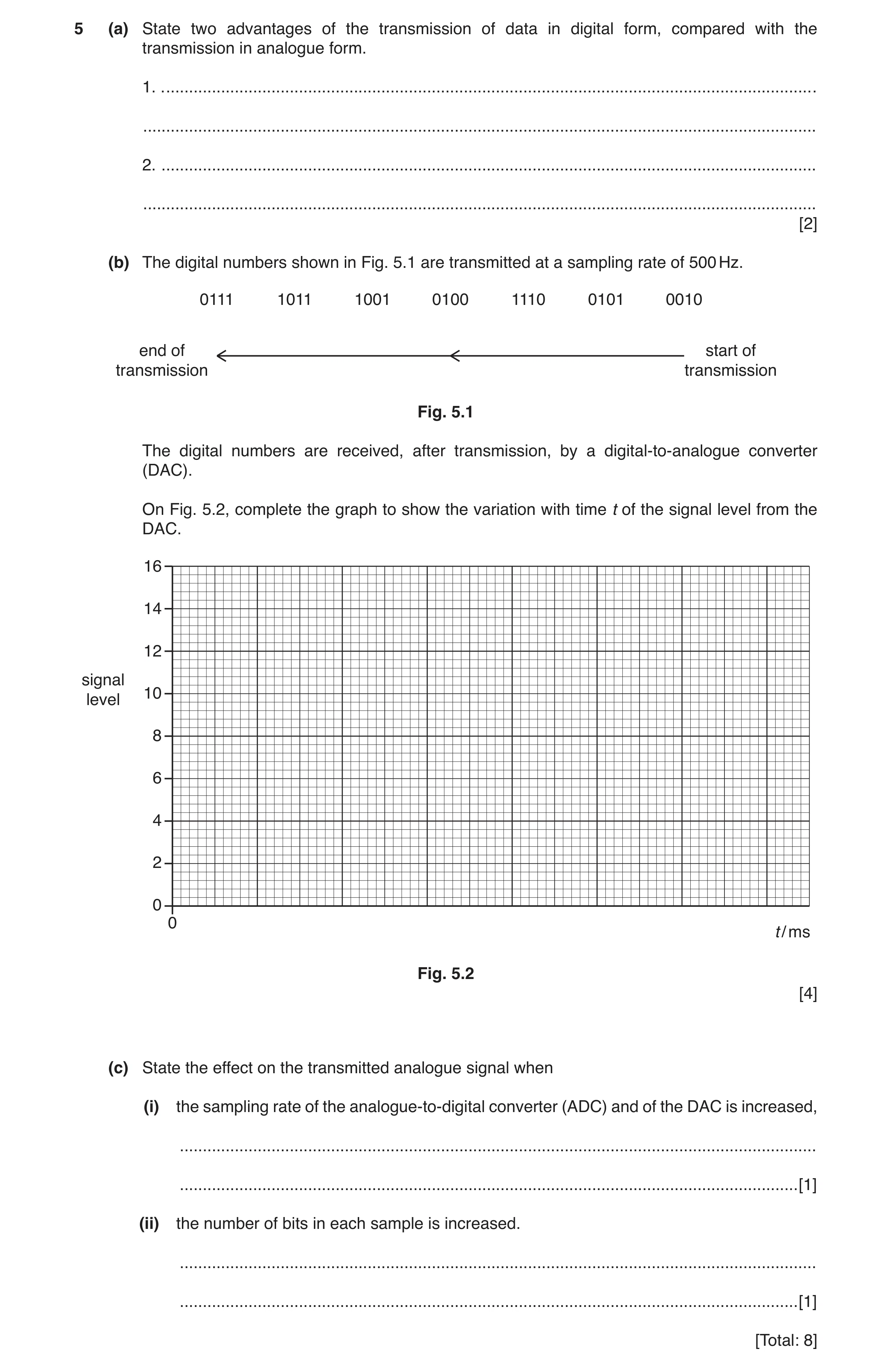
5 (a) State two advantages of the transmission of data in digital form, compared with the transmission in analogue form. 1. . … … 2. … … [2] (b) The digital numbers shown in Fig. 5.1 are transmitted at a sampling rate of 500 Hz. 0111 1011 1001 0100 1110 0101 0010 end of start of transmission transmission Fig. 5.1 The digital numbers are received, after transmission, by a digital-to-analogue converter (DAC). On Fig. 5.2, complete the graph to show the variation with time t of the signal level from the DAC. 16 14 12 signal 10 level 8 6 4 2 0 0 t / ms Fig. 5.2 [4] (c) State the effect on the transmitted analogue signal when (i) the sampling rate of the analogue-to-digital converter (ADC) and of the DAC is increased, … … [1] (ii) the number of bits in each sample is increased. … … [1] [Total: 8]
8 marks
Mark scheme: 5(a) Any two reasonable suggestions e.g.: • noise can be eliminated/(signal/data) can be regenerated • bits can be added to correct for errors • data compression/multiplexing (is possible) • signal can be encrypted/better security B2 5(b) sketch: series of seven steps B1 each step width 2 ms B1 correct levels in correct order (2, 5, 14, 4, 9, 11, 7) (1 mark for 6 levels correct, 2 marks for 7 levels correct) A2 5(c)(i) step width reduced or higher frequencies can be reproduced B1 5(c)(ii) step height reduced or smaller changes in signal (intensity) can be reproduced B1
This question in 9702/41 Oct/Nov 2018
Q8 · The root-mean-square (r.m.s.) value of the voltage of a sinusoidal alternating supply is… 9702/42 Oct/Nov 2018
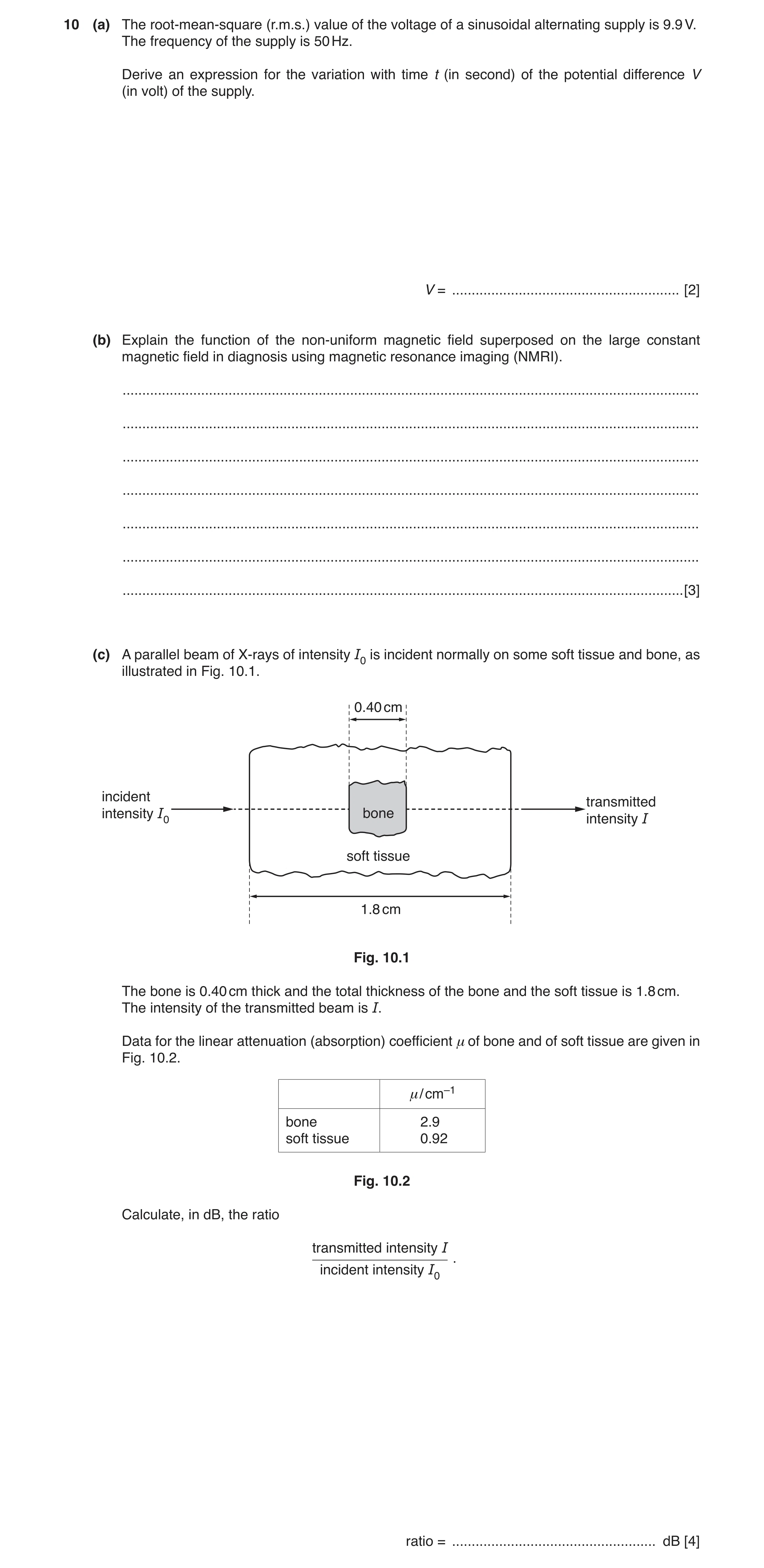
10 (a) The root-mean-square (r.m.s.) value of the voltage of a sinusoidal alternating supply is 9.9 V. The frequency of the supply is 50 Hz. Derive an expression for the variation with time t (in second) of the potential difference V (in volt) of the supply. V = … [2] (b) Explain the function of the non-uniform magnetic field superposed on the large constant magnetic field in diagnosis using magnetic resonance imaging (NMRI). … … … … … … … [3] (c) A parallel beam of X-rays of intensity I0 is incident normally on some soft tissue and bone, as illustrated in Fig. 10.1. 0.40 cm incident transmitted intensity I0 bone intensity I soft tissue 1.8 cm Fig. 10.1 The bone is 0.40 cm thick and the total thickness of the bone and the soft tissue is 1.8 cm. The intensity of the transmitted beam is I. Data for the linear attenuation (absorption) coefficient μ of bone and of soft tissue are given in Fig. 10.2. μ/ cm–1 bone 2.9 soft tissue 0.92 Fig. 10.2 Calculate, in dB, the ratio transmitted intensity I . incident intensity I0 ratio = … dB [4]
9 marks
Mark scheme: 10(a) and ω = 2πf = 2π × 50 (= 314 rad s–1) C1 V = 14 sin 314t A1 10(b) enables (resonating) nuclei to be located B1 resonant frequency depends on magnetic field strength B1 Any one from: • non-uniform field is (accurately) calibrated • (non-uniform) field may be varied to enable detection in different positions • unique (magnetic) field strength/frequency at each point B1 10(c) I = I0 exp(–µx) C1 I = I0 [exp(–µx)bone × exp(–µx)soft tissue] I = I0 [exp(–2.9 × 0.40) × exp(–0.92 × 1.4)] C1 I / I0 = 0.0865 C1 ratio / dB = 10 lg 0.0865 = –11 dB A1
This question in 9702/42 Oct/Nov 2018
Q9 · State two advantages of the transmission of data in digital form, compared with the… 9702/43 Oct/Nov 2018
5 (a) State two advantages of the transmission of data in digital form, compared with the transmission in analogue form. 1. . … … 2. … … [2] (b) The digital numbers shown in Fig. 5.1 are transmitted at a sampling rate of 500 Hz. 0111 1011 1001 0100 1110 0101 0010 end of start of transmission transmission Fig. 5.1 The digital numbers are received, after transmission, by a digital-to-analogue converter (DAC). On Fig. 5.2, complete the graph to show the variation with time t of the signal level from the DAC. 16 14 12 signal 10 level 8 6 4 2 0 0 t / ms Fig. 5.2 [4] (c) State the effect on the transmitted analogue signal when (i) the sampling rate of the analogue-to-digital converter (ADC) and of the DAC is increased, … … [1] (ii) the number of bits in each sample is increased. … … [1] [Total: 8]
8 marks
Mark scheme: 5(a) Any two reasonable suggestions e.g.: • noise can be eliminated/(signal/data) can be regenerated • bits can be added to correct for errors • data compression/multiplexing (is possible) • signal can be encrypted/better security B2 5(b) sketch: series of seven steps B1 each step width 2 ms B1 correct levels in correct order (2, 5, 14, 4, 9, 11, 7) (1 mark for 6 levels correct, 2 marks for 7 levels correct) A2 5(c)(i) step width reduced or higher frequencies can be reproduced B1 5(c)(ii) step height reduced or smaller changes in signal (intensity) can be reproduced B1
This question in 9702/43 Oct/Nov 2018
Q10 · A horseshoe magnet is placed on a top pan balance 9702/42 Feb/March 2019
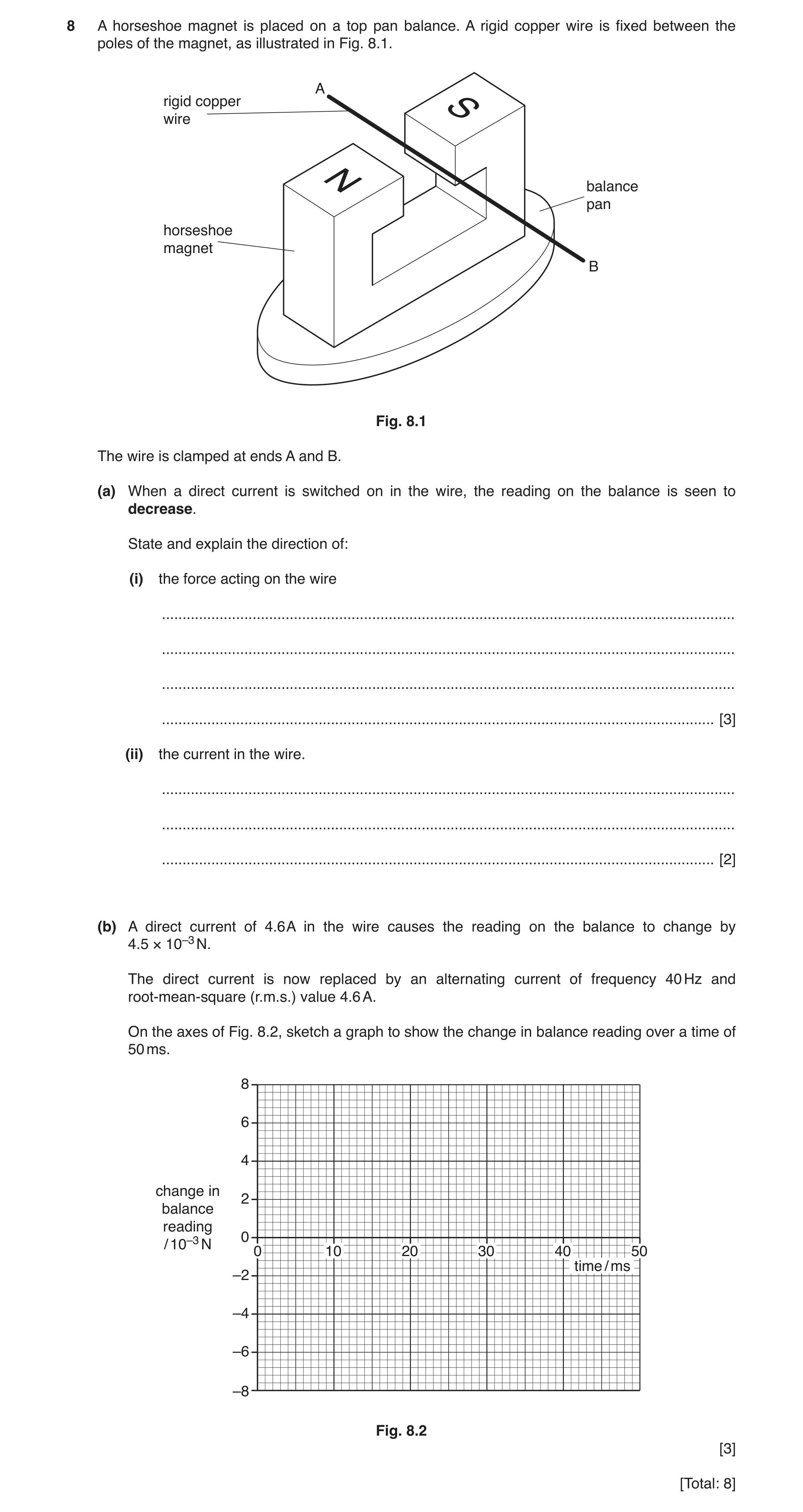
8 A horseshoe magnet is placed on a top pan balance. A rigid copper wire is fixed between the poles of the magnet, as illustrated in Fig. 8.1. A rigid copper wire balance pan horseshoe magnet B Fig. 8.1 The wire is clamped at ends A and B. (a) When a direct current is switched on in the wire, the reading on the balance is seen to decrease. State and explain the direction of: (i) the force acting on the wire … … … … [3] (ii) the current in the wire. … … … [2] (b) A direct current of 4.6 A in the wire causes the reading on the balance to change by 4.5 × 10⁻³ N. The direct current is now replaced by an alternating current of frequency 40 Hz and root-mean-square (r.m.s.) value 4.6 A. On the axes of Fig. 8.2, sketch a graph to show the change in balance reading over a time of 50 ms. 8 6 4 change in 2 balance reading 0 / 10–3 N 0 10 20 30 40 50 time / ms –2 –4 –6 –8 Fig. 8.2 [3] [Total: 8]
8 marks
Mark scheme: 8(a)(i) Either Newton’s third law or equal and opposite forces B1 force on magnet is upwards B1 so force on wire downwards B1 8(a)(ii) using (Fleming’s) left-hand rule M1 current from B to A A1 8(b) sinusoidal wave with at least 1 cycle B1 peaks at +6.4 mN and –6.4 mN B1 time period 25 ms B1
This question in 9702/42 Feb/March 2019
Q11 · A bridge rectifier contains four diodes 9702/41 May/June 2019
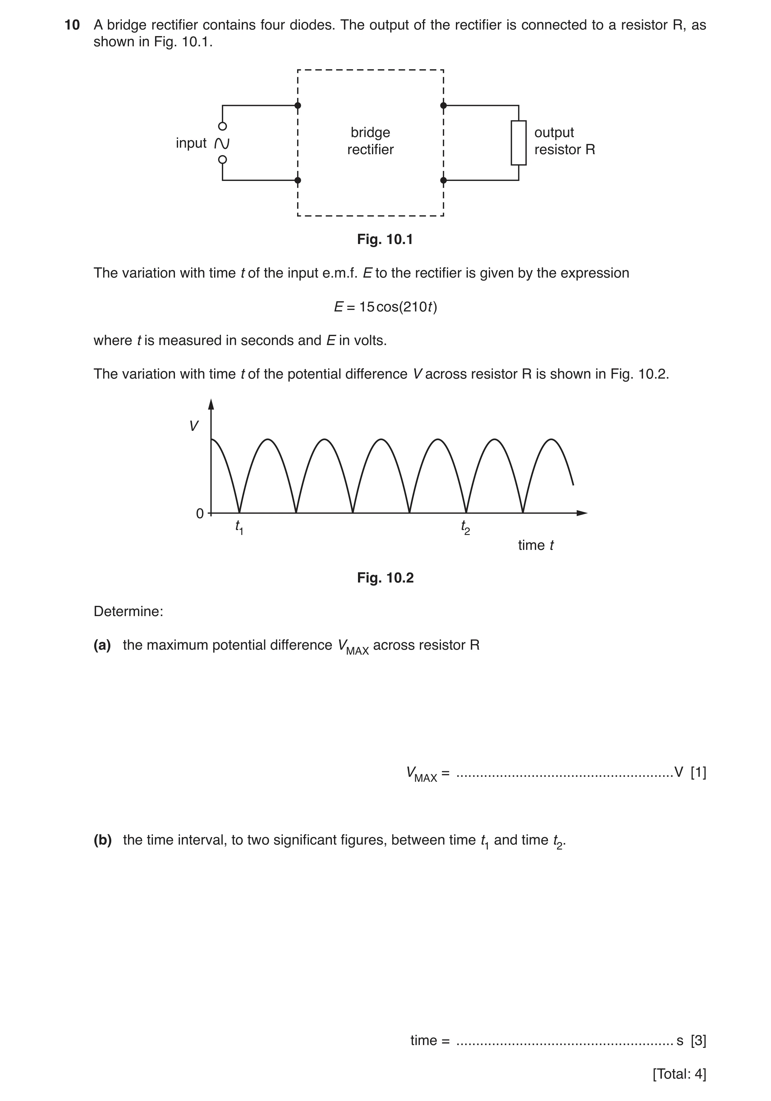
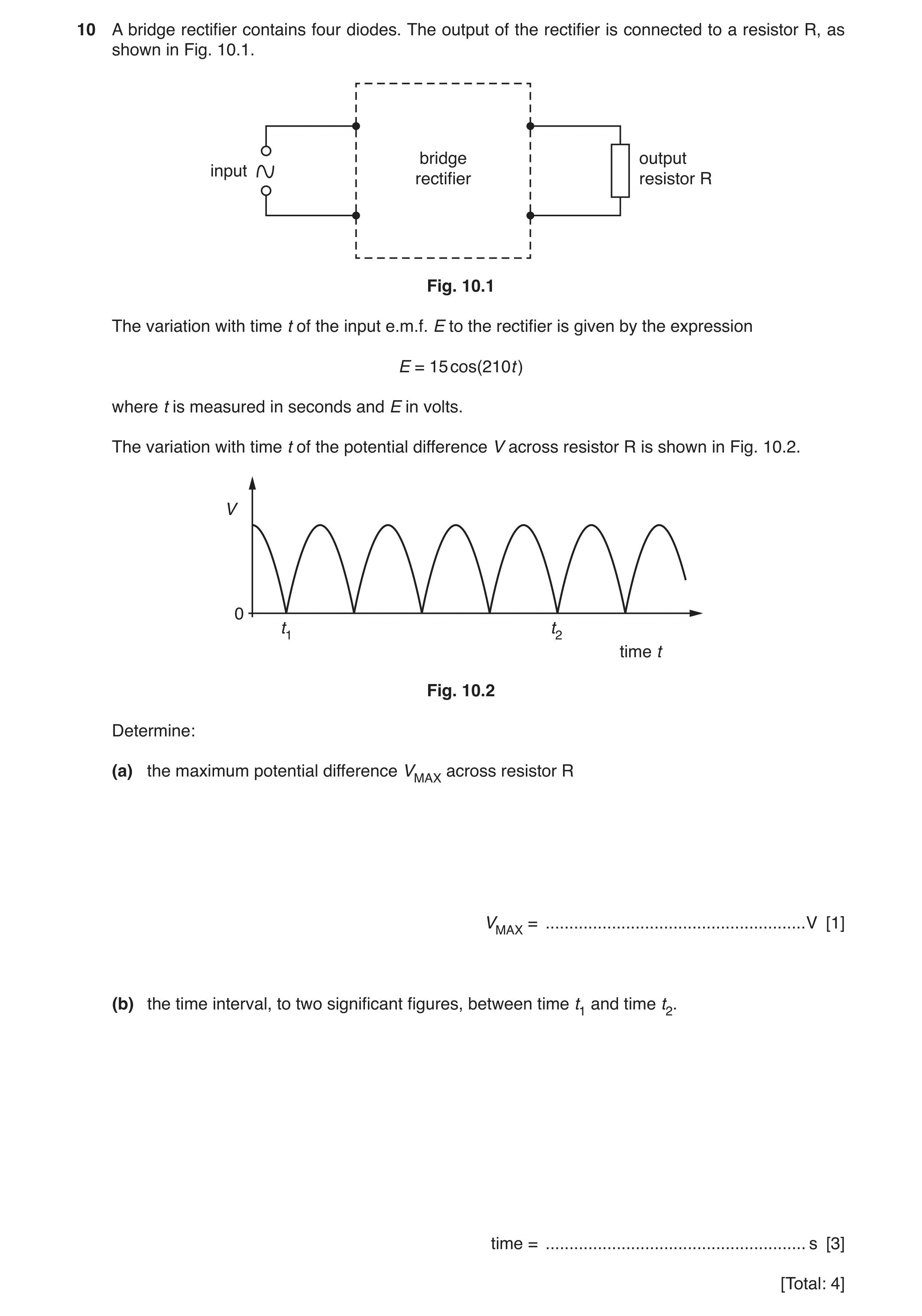
10 A bridge rectifier contains four diodes. The output of the rectifier is connected to a resistor R, as shown in Fig. 10.1. bridge output input rectifier resistor R Fig. 10.1 The variation with time t of the input e.m.f. E to the rectifier is given by the expression E = 15 cos(210t ) where t is measured in seconds and E in volts. The variation with time t of the potential difference V across resistor R is shown in Fig. 10.2. V 0 t1 t2 time t Fig. 10.2 Determine: (a) the maximum potential difference VMAX across resistor R VMAX = … V [1] (b) the time interval, to two significant figures, between time t1 and time t2. time = … s [3] [Total: 4]
4 marks
Mark scheme: 10(a) VMAX = 15 V A1 10(b) 210 = 2π / T C1 T = 0.0299 s C1 (t2 – t1) = 0.060 s A1
This question in 9702/41 May/June 2019
Q12 · State Faraday’s law of electromagnetic induction 9702/42 May/June 2019
10 (a) State Faraday’s law of electromagnetic induction. … … … [2] (b) An ideal transformer is illustrated in Fig. 10.1. soft-iron core load E resistor primary coil secondary coil 2700 turns 450 turns Fig. 10.1 Explain why, when there is an alternating current in the primary coil, there is a current in the load resistor. … … … … … [3] (c) The primary coil in (b) has 2700 turns. The secondary coil has 450 turns. The e.m.f. E applied across the primary coil is given by the expression E = 220 sin(100πt ) where E is measured in volts and t is the time in seconds. Calculate the root-mean-square (r.m.s.) e.m.f. induced in the secondary coil. r.m.s. e.m.f. = … V [3] [Total: 8]
8 marks
Mark scheme: 10(a) (induced) e.m.f. proportional to rate M1 of change of (magnetic) flux (linkage) A1 10(b) current in primary coil gives rise to magnetic flux B1 changing (magnetic) flux in core links with secondary coil B1 induced e.m.f. (in secondary coil) causes current in load/resistor B1 10(c) correct application of turns ratio: to peak voltage ratio, giving (V0 / 220) = (450 / 2700) or to r.m.s. voltage ratio, giving (Vr.m.s. / 156) = (450 / 2700) C1 correct application of √2 factor: to peak applied e.m.f., giving 220 / √2 or to peak output em.f., giving 37 / √2 C1 Vr.m.s. = 26 V A1
This question in 9702/42 May/June 2019
Q13 · A bridge rectifier contains four diodes 9702/43 May/June 2019
10 A bridge rectifier contains four diodes. The output of the rectifier is connected to a resistor R, as shown in Fig. 10.1. bridge output input rectifier resistor R Fig. 10.1 The variation with time t of the input e.m.f. E to the rectifier is given by the expression E = 15 cos(210t ) where t is measured in seconds and E in volts. The variation with time t of the potential difference V across resistor R is shown in Fig. 10.2. V 0 t1 t2 time t Fig. 10.2 Determine: (a) the maximum potential difference VMAX across resistor R VMAX = … V [1] (b) the time interval, to two significant figures, between time t1 and time t2. time = … s [3] [Total: 4]
4 marks
Mark scheme: 10(a) VMAX = 15 V A1 10(b) 210 = 2π / T C1 T = 0.0299 s C1 (t2 – t1) = 0.060 s A1
This question in 9702/43 May/June 2019
Q14 · The output of a power supply is represented by: V = 9.0 sin 20t where V is the potential… 9702/42 Feb/March 2020
9 (a) The output of a power supply is represented by: V = 9.0 sin 20t where V is the potential difference in volts and t is the time in seconds. Determine, for the output of the supply: (i) the root-mean-square (r.m.s.) voltage, Vr.m.s. Vr.m.s = … V [1] (ii) the period T. T = … s [2] (b) The variations with time t of the output potential difference V from two different power supplies are shown in Fig. 9.1 and Fig. 9.2. Vo Vo V V 0 0 0 t 0 t Fig. 9.1 Fig. 9.2 The graphs are drawn to the same scale. State and explain whether the same power would be dissipated in a 1.0 Ω resistor connected to each power supply. … … … [1] (c) (i) The power supply in (a) is connected to a transformer. The input power to the transformer is 80 W. The secondary coil is connected to a resistor. The r.m.s. voltage across the resistor is 120 V. The r.m.s. current in the secondary coil is 0.64 A. Calculate the efficiency of the transformer. efficiency = … [3] (ii) State one reason why the transformer is not 100% efficient. … … [1] [Total: 8]
8 marks
Mark scheme: 9(a)(i) 9.0 / √2 = 6.4 V A1 9(a)(ii) ω = 20 ω = 2π / T T = 2π / 20 C1 T = 0.31 s A1 9(b) the r.m.s. voltages are different, so no B1 9(c)(i) P = Vr.m.s. × Ir.m.s. C1 = 120 × 0.64 = 76.8 W C1 efficiency = (76.8 / 80) × 100 = 0.96 or 96 % A1 9(c)(ii) Any one from: • heat losses due to resistance of windings / coils • heat losses in magnetising and demagnetising core / hysteresis losses in core • heat losses due to eddy currents in (iron) core • loss of flux linkage B1
This question in 9702/42 Feb/March 2020
Q15 · The output potential difference (p.d.) of an alternating power supply is represented by V… 9702/42 Feb/March 2021
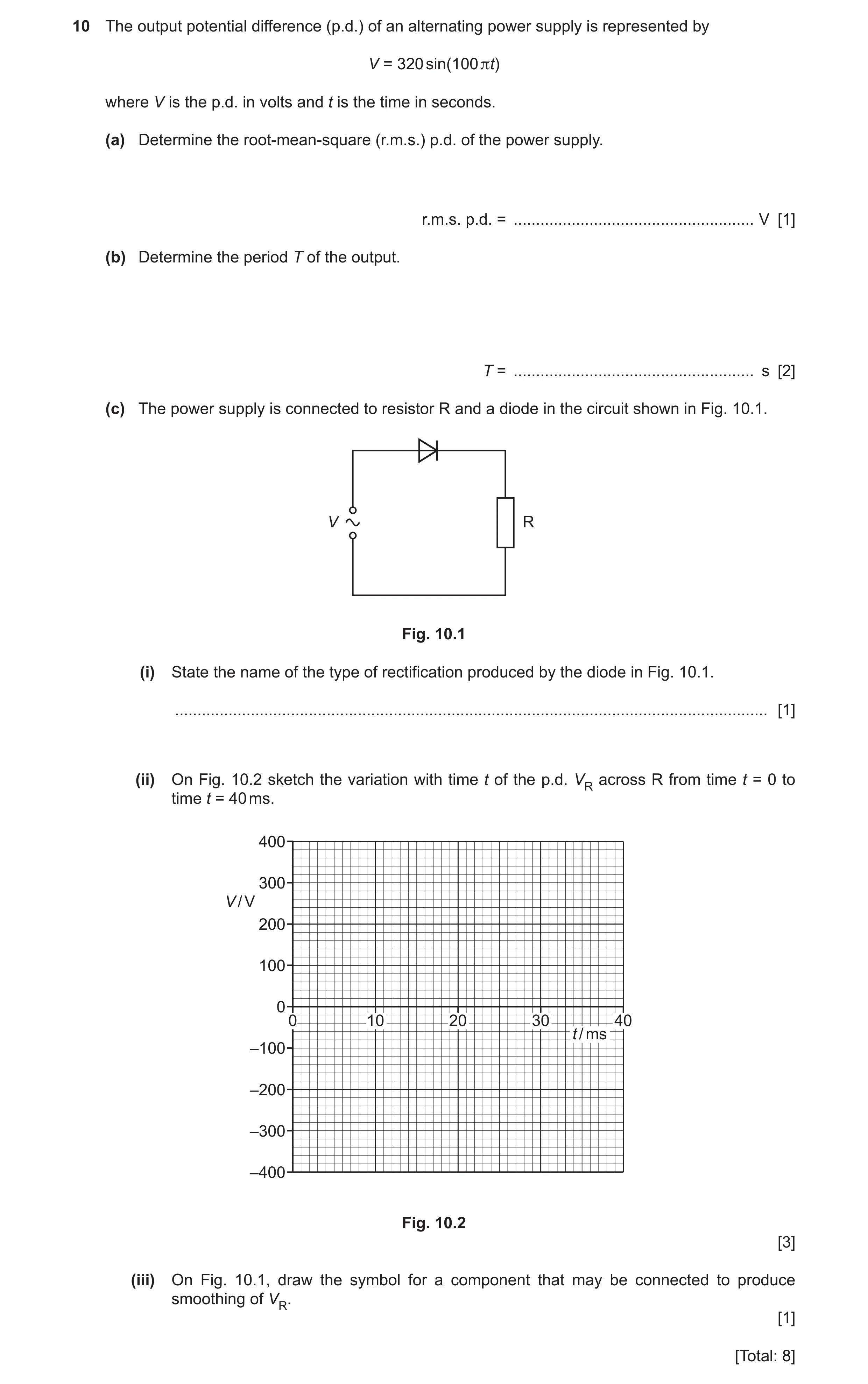
10 The output potential difference (p.d.) of an alternating power supply is represented by V = 320 sin(100 πt) where V is the p.d. in volts and t is the time in seconds. (a) Determine the root-mean-square (r.m.s.) p.d. of the power supply. r.m.s. p.d. = … V [1] (b) Determine the period T of the output. T = … s [2] (c) The power supply is connected to resistor R and a diode in the circuit shown in Fig. 10.1. V R Fig. 10.1 (i) State the name of the type of rectification produced by the diode in Fig. 10.1. … [1] (ii) On Fig. 10.2 sketch the variation with time t of the p.d. VR across R from time t = 0 to time t = 40 ms. 400 300 V / V 200 100 0 0 10 20 30 40 t / ms –100 –200 –300 –400 Fig. 10.2 [3] (iii) On Fig. 10.1, draw the symbol for a component that may be connected to produce smoothing of VR. [1] [Total: 8]
8 marks
Mark scheme: 10(a) 230 V A1 10(b) ω = 100π 2 2 100 T π π ω π = = C1 0.020 s = A1 10(c)(i) half-wave (rectification) B1 10(c)(ii) sinusoidal half waves in positive V only or negative V only, peak at 320 V B1 line at zero for second half of cycle B1 two time periods shown, each of 0.020 s B1 10(c)(iii) capacitor added in parallel with resistor B1
This question in 9702/42 Feb/March 2021
Q16 · By reference to heating effect, explain what is meant by the root-mean-square (r.m.s.)… 9702/42 May/June 2021
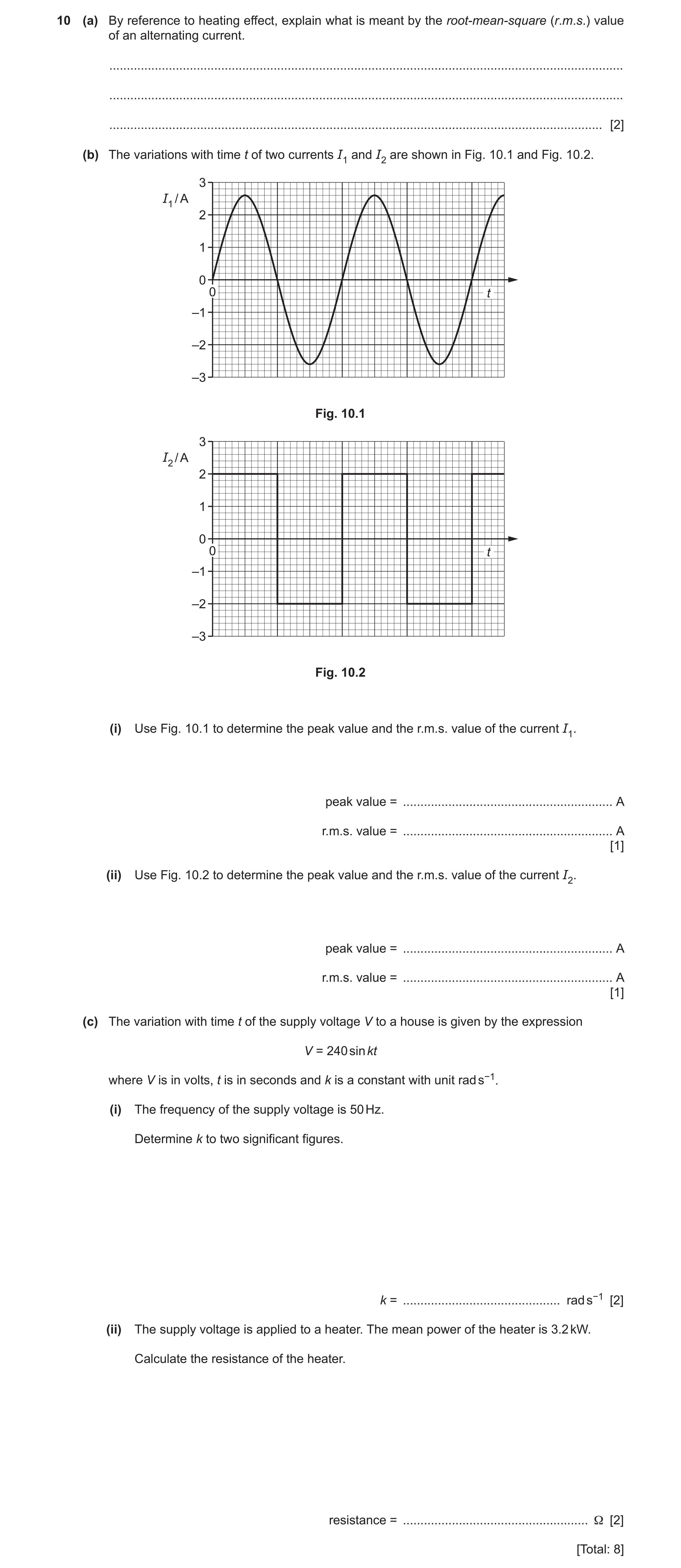
10 (a) By reference to heating effect, explain what is meant by the root-mean-square (r.m.s.) value of an alternating current. … … … [2] (b) The variations with time t of two currents I1 and I2 are shown in Fig. 10.1 and Fig. 10.2. 3 I1 / A 2 1 0 0 t –1 –2 –3 Fig. 10.1 3 I2 / A 2 1 0 0 t –1 –2 –3 Fig. 10.2 (i) Use Fig. 10.1 to determine the peak value and the r.m.s. value of the current I1. peak value = … A r.m.s. value = … A [1] (ii) Use Fig. 10.2 to determine the peak value and the r.m.s. value of the current I2. peak value = … A r.m.s. value = … A [1] (c) The variation with time t of the supply voltage V to a house is given by the expression V = 240 sin kt where V is in volts, t is in seconds and k is a constant with unit rad s−1. (i) The frequency of the supply voltage is 50 Hz. Determine k to two significant figures. k = … rad s−1 [2] (ii) The supply voltage is applied to a heater. The mean power of the heater is 3.2 kW. Calculate the resistance of the heater. resistance = … Ω [2] [Total: 8]
8 marks
Mark scheme: 10(a) the steady current or the direct current M1 that produces the same heating effect (as the alternating current) A1 10(b)(i) peak current = 2.6 A and r.m.s. current = 1.8 A A1 10(b)(ii) peak current = 2.0 A and r.m.s. current = 2.0 A A1 10(c)(i) k = 2πf C1 = 2π × 50 = 310 rad s–1 A1 10(c)(ii) power = VRMS2 / R or power = V02 / 2R C1 R = (240 / √2)2 / 3200 or R = 2402 / (2 × 3200) R = 9.0 Ω A1
This question in 9702/42 May/June 2021
Q17 · State, by reference to the power dissipated in a resistor, what is meant by the… 9702/41 Oct/Nov 2021
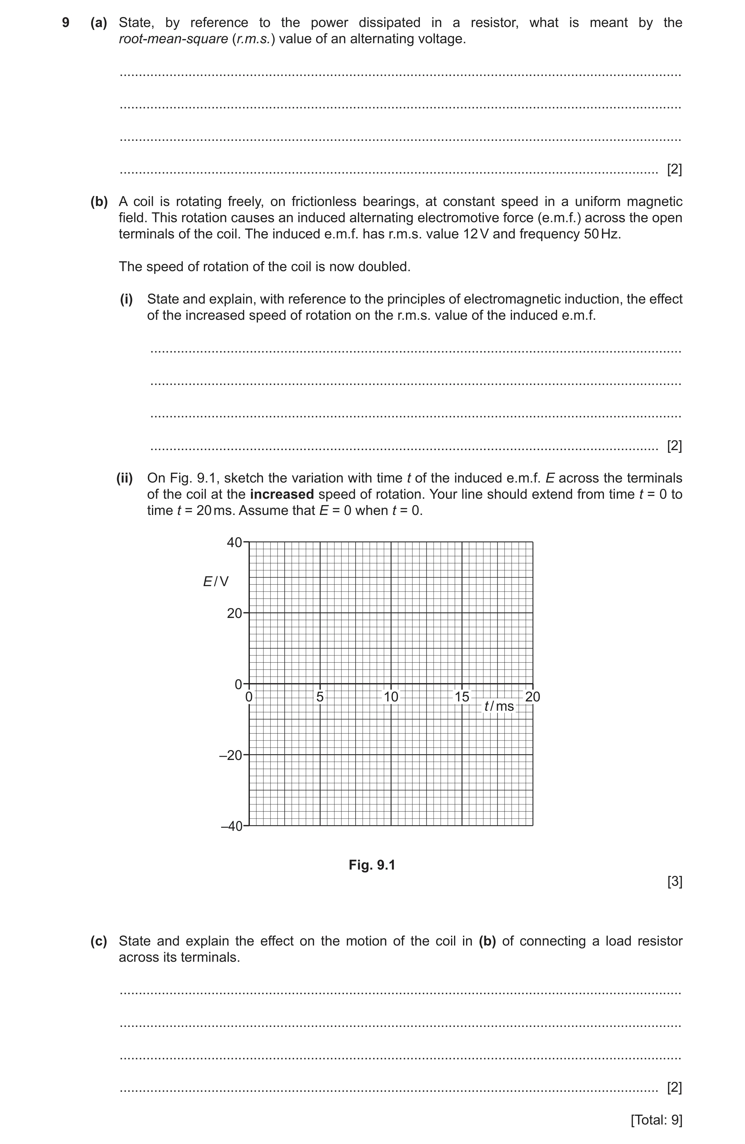
9 (a) State, by reference to the power dissipated in a resistor, what is meant by the root-mean-square (r.m.s.) value of an alternating voltage. … … … … [2] (b) A coil is rotating freely, on frictionless bearings, at constant speed in a uniform magnetic field. This rotation causes an induced alternating electromotive force (e.m.f.) across the open terminals of the coil. The induced e.m.f. has r.m.s. value 12 V and frequency 50 Hz. The speed of rotation of the coil is now doubled. (i) State and explain, with reference to the principles of electromagnetic induction, the effect of the increased speed of rotation on the r.m.s. value of the induced e.m.f. … … … … [2] (ii) On Fig. 9.1, sketch the variation with time t of the induced e.m.f. E across the terminals of the coil at the increased speed of rotation. Your line should extend from time t = 0 to time t = 20 ms. Assume that E = 0 when t = 0. 40 E / V 20 0 0 5 10 15 20 t / ms –20 –40 Fig. 9.1 [3] (c) State and explain the effect on the motion of the coil in (b) of connecting a load resistor across its terminals. … … … … [2] [Total: 9]
9 marks
Mark scheme: 9(a) constant voltage M1 that produces/dissipates same power as (the mean power of) the alternating voltage A1 9(b)(i) (maximum) rate of cutting of (magnetic) flux doubles B1 (peak and hence) r.m.s. induced e.m.f. doubles B1 9(b)(ii) sketch: (sinusoidal) wave of period 10 ms B1 peak E shown as ± 34 V (1 mark out of 2 awarded if peak E shown as ± 17 V or ± 24 V) B2 9(c) current in the coil results in forces that oppose its rotation or current in the resistor dissipates the energy of rotation B1 coil stops rotating B1
This question in 9702/41 Oct/Nov 2021
Q18 · State, by reference to the power dissipated in a resistor, what is meant by the… 9702/43 Oct/Nov 2021
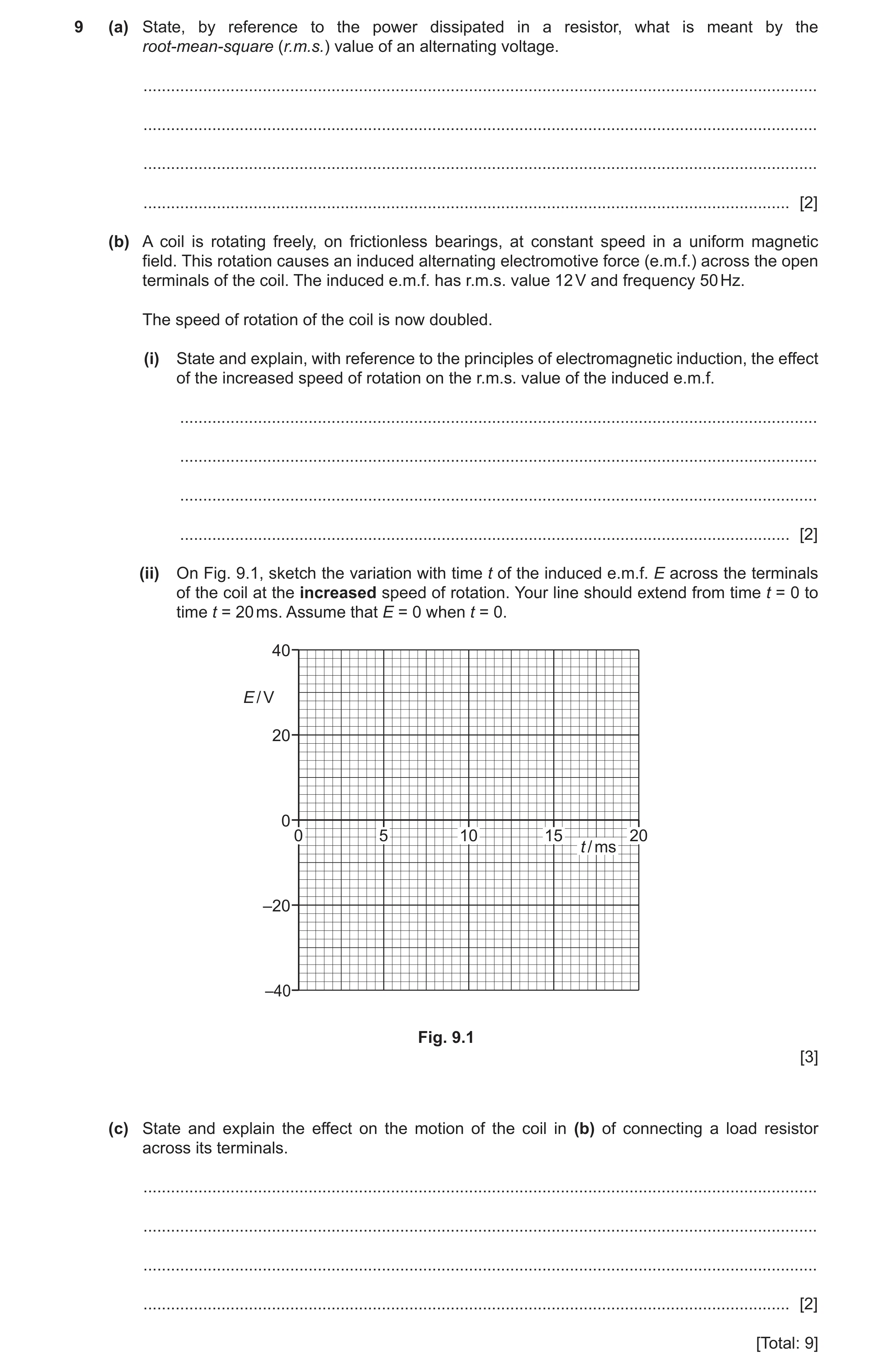
9 (a) State, by reference to the power dissipated in a resistor, what is meant by the root-mean-square (r.m.s.) value of an alternating voltage. … … … … [2] (b) A coil is rotating freely, on frictionless bearings, at constant speed in a uniform magnetic field. This rotation causes an induced alternating electromotive force (e.m.f.) across the open terminals of the coil. The induced e.m.f. has r.m.s. value 12 V and frequency 50 Hz. The speed of rotation of the coil is now doubled. (i) State and explain, with reference to the principles of electromagnetic induction, the effect of the increased speed of rotation on the r.m.s. value of the induced e.m.f. … … … … [2] (ii) On Fig. 9.1, sketch the variation with time t of the induced e.m.f. E across the terminals of the coil at the increased speed of rotation. Your line should extend from time t = 0 to time t = 20 ms. Assume that E = 0 when t = 0. 40 E / V 20 0 0 5 10 15 20 t / ms –20 –40 Fig. 9.1 [3] (c) State and explain the effect on the motion of the coil in (b) of connecting a load resistor across its terminals. … … … … [2] [Total: 9]
9 marks
Mark scheme: 9(a) constant voltage M1 that produces/dissipates same power as (the mean power of) the alternating voltage A1 9(b)(i) (maximum) rate of cutting of (magnetic) flux doubles B1 (peak and hence) r.m.s. induced e.m.f. doubles B1 9(b)(ii) sketch: (sinusoidal) wave of period 10 ms B1 peak E shown as ± 34 V (1 mark out of 2 awarded if peak E shown as ± 17 V or ± 24 V) B2 9(c) current in the coil results in forces that oppose its rotation or current in the resistor dissipates the energy of rotation B1 coil stops rotating B1
This question in 9702/43 Oct/Nov 2021
Q19 · Alternating current (a.c.) is converted into direct current (d.c.) using a full-wave… 9702/42 Feb/March 2022
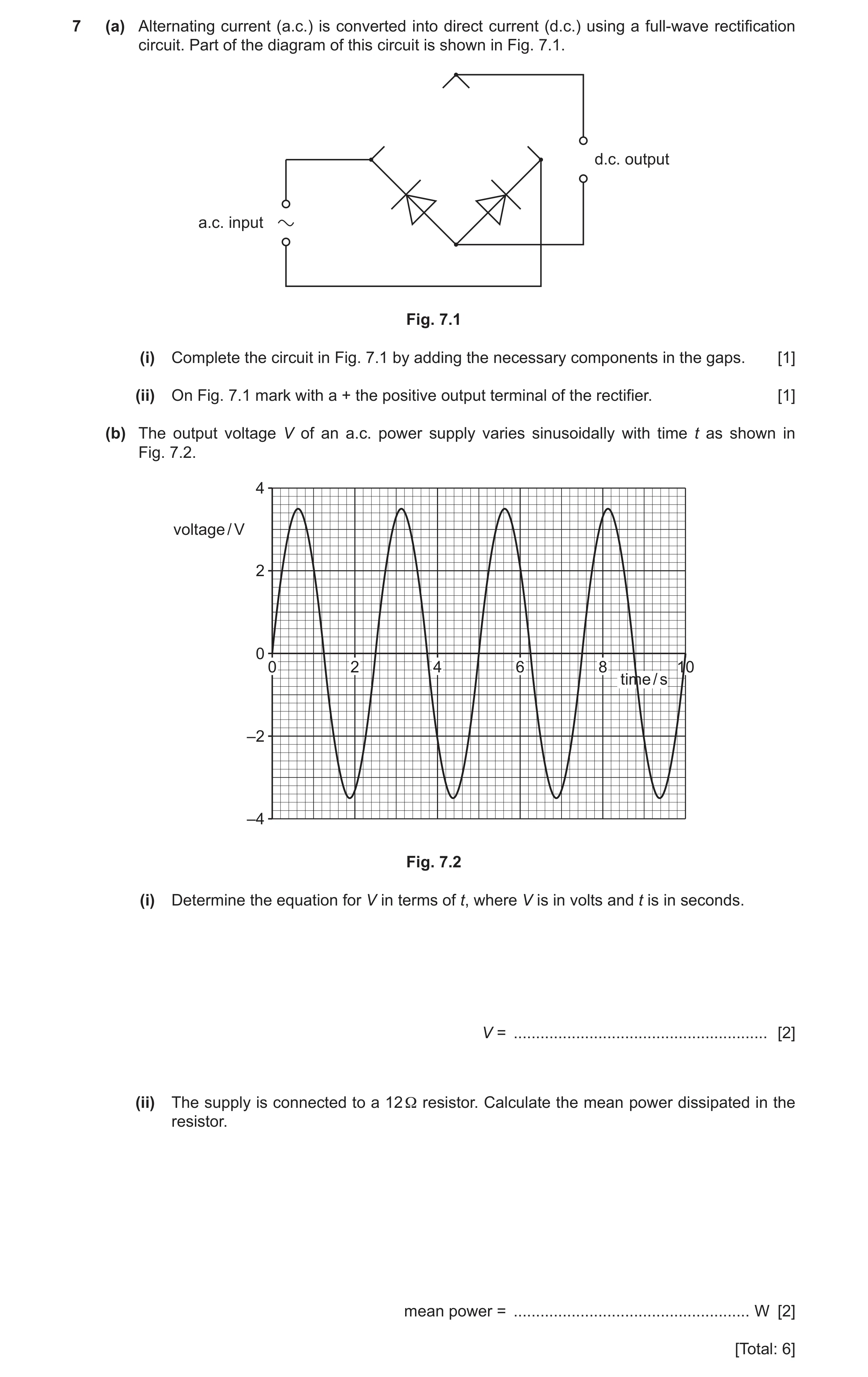
7 (a) Alternating current (a.c.) is converted into direct current (d.c.) using a full-wave rectification circuit. Part of the diagram of this circuit is shown in Fig. 7.1. d.c. output a.c. input Fig. 7.1 (i) Complete the circuit in Fig. 7.1 by adding the necessary components in the gaps. [1] (ii) On Fig. 7.1 mark with a + the positive output terminal of the rectifier. [1] (b) The output voltage V of an a.c. power supply varies sinusoidally with time t as shown in Fig. 7.2. 4 voltage / V 2 0 0 2 4 6 8 10 time / s –2 –4 Fig. 7.2 (i) Determine the equation for V in terms of t, where V is in volts and t is in seconds. V = … [2] (ii) The supply is connected to a 12 Ω resistor. Calculate the mean power dissipated in the resistor. mean power = … W [2] [Total: 6]
6 marks
Mark scheme: 7(a)(i) two diodes added in correct directions (Both diodes pointing inwards and upwards), correct symbols only B1 7(a)(ii) ‘+’ anywhere on upper output wire B1 7(b)(i) ω = 2π / T = 2π / 2.5 = 0.80 π or 4π / 5 or 2.5 C1 (V =) 3.5 sin (0.8π t) or 3.5 sin (4π t / 5) or 3.5 sin (2.5 t) A1 Question Answer Marks 7(b)(ii) 2 V (P=) 2R or 2 . . . (P=) R r m s V 2 3.5 = 2 12 × or 2 2.47 12 C1 = 0.51 W A1
This question in 9702/42 Feb/March 2022
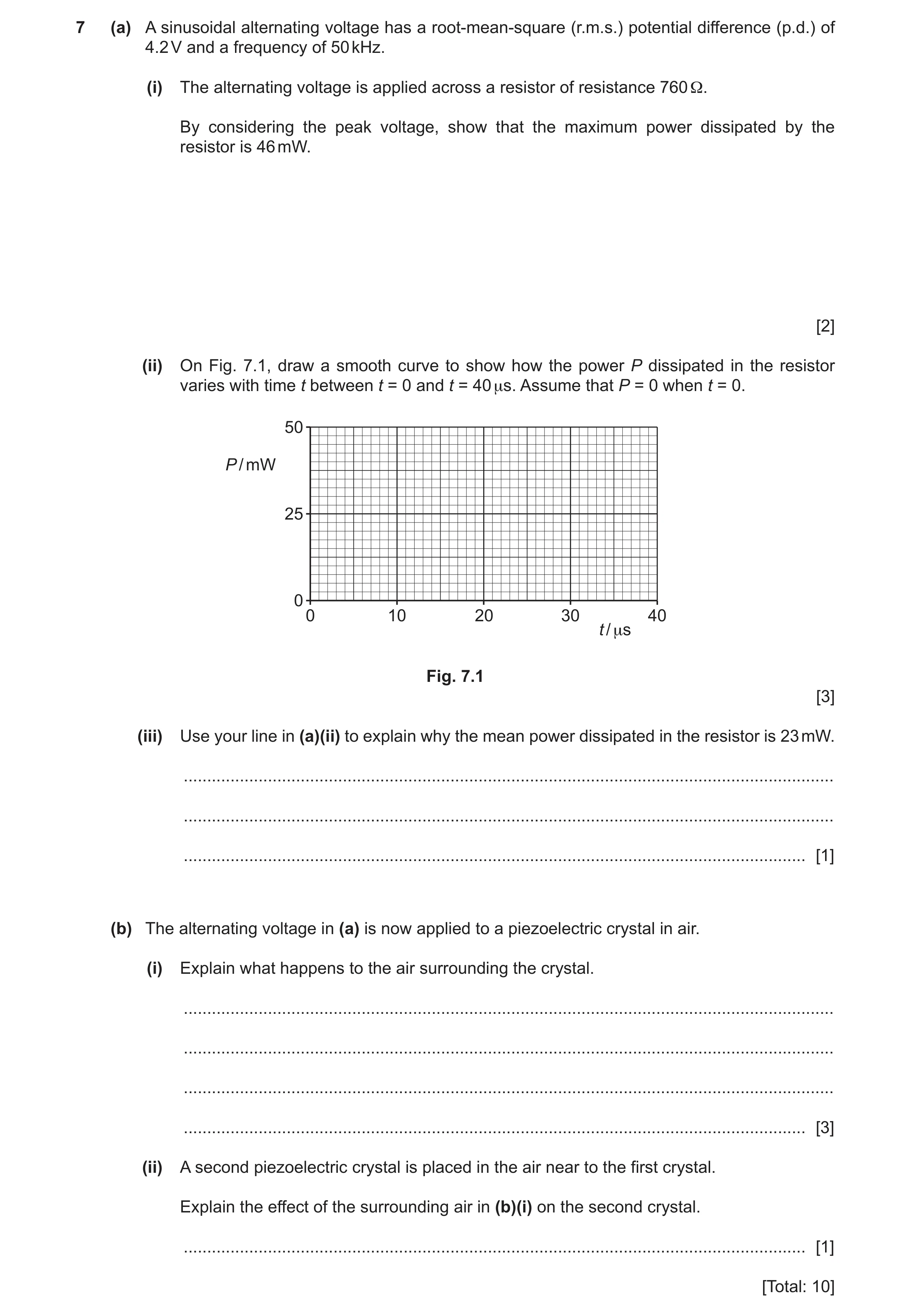
Q20 · A sinusoidal alternating voltage has a root-mean-square (r.m.s.) potential difference… 9702/41 Oct/Nov 2022
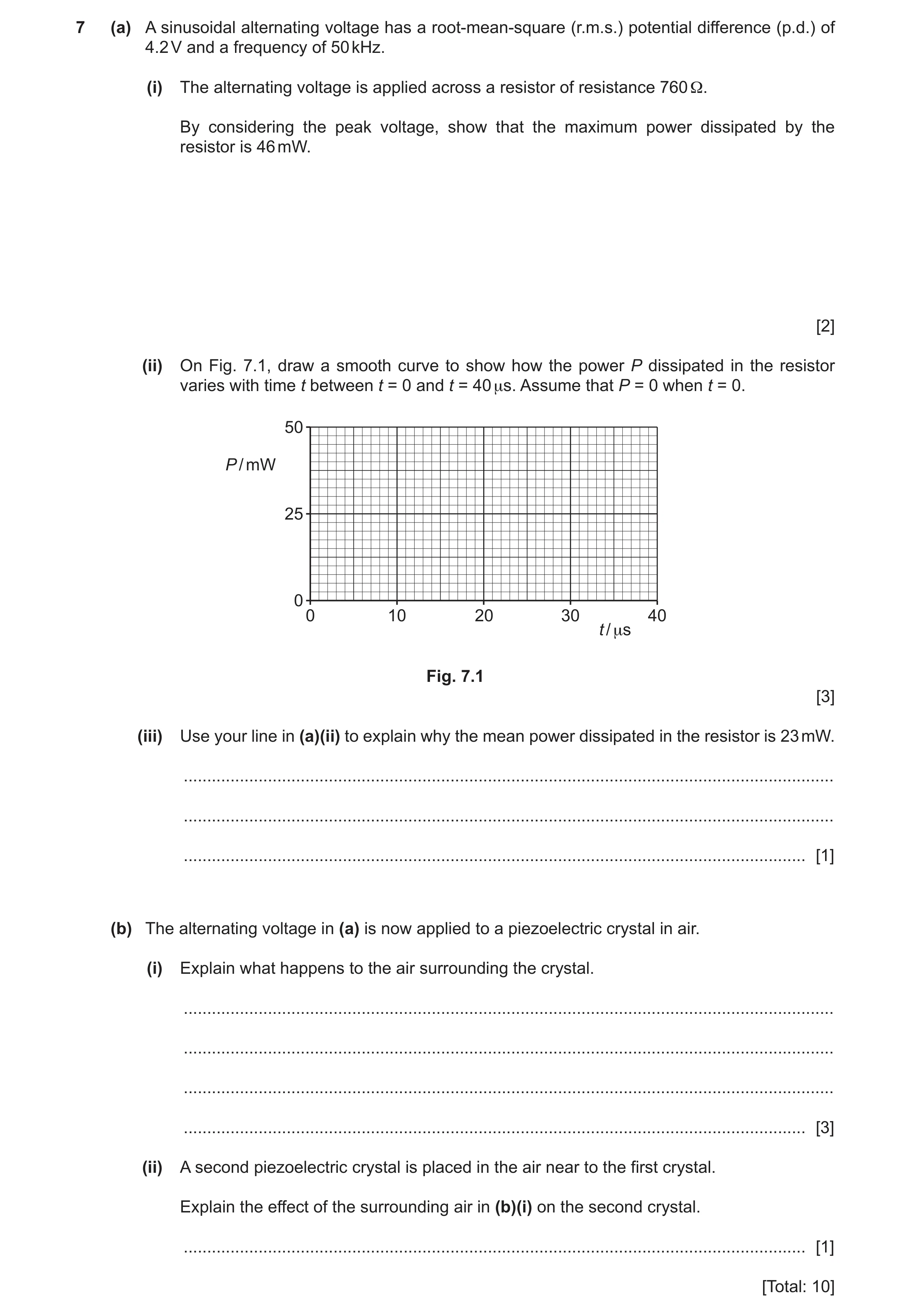
7 (a) A sinusoidal alternating voltage has a root-mean-square (r.m.s.) potential difference (p.d.) of 4.2 V and a frequency of 50 kHz. (i) The alternating voltage is applied across a resistor of resistance 760 Ω. By considering the peak voltage, show that the maximum power dissipated by the resistor is 46 mW. [2] (ii) On Fig. 7.1, draw a smooth curve to show how the power P dissipated in the resistor varies with time t between t = 0 and t = 40 μs. Assume that P = 0 when t = 0. 50 P / mW 25 0 0 10 20 30 40 t / μs Fig. 7.1 [3] (iii) Use your line in (a)(ii) to explain why the mean power dissipated in the resistor is 23 mW. … … … [1] (b) The alternating voltage in (a) is now applied to a piezoelectric crystal in air. (i) Explain what happens to the air surrounding the crystal. … … … … [3] (ii) A second piezoelectric crystal is placed in the air near to the first crystal. Explain the effect of the surrounding air in (b)(i) on the second crystal. … [1] [Total: 10]
10 marks
Mark scheme: 7(a)(i) peak voltage = 4.2 2 B1 ( = 5.9 V) power = V2 / R A1 = 5.92 / 760 = 0.046 W or 46 mW 7(a)(ii) sketch shows peak(s) in power at 46 mW B1 correct shape (sinusoidal wave sitting on t-axis) B1 four cycles of repeating pattern shown, with P = 0 at 0, 10, 20, 30, 40 s B1 7(a)(iii) line is symmetrical about 23 mW B1 7(b)(i) (alternating p.d. makes) the crystal vibrate B1 vibrations (of crystal) causes air to vibrate B1 frequency is in ultrasound range B1 7(b)(ii) (air makes) crystal vibrate, which causes an e.m.f. to be generated across the (second) crystal B1
This question in 9702/41 Oct/Nov 2022
Q21 · A sinusoidal alternating voltage has a root-mean-square (r.m.s.) potential difference… 9702/43 Oct/Nov 2022
7 (a) A sinusoidal alternating voltage has a root-mean-square (r.m.s.) potential difference (p.d.) of 4.2 V and a frequency of 50 kHz. (i) The alternating voltage is applied across a resistor of resistance 760 Ω. By considering the peak voltage, show that the maximum power dissipated by the resistor is 46 mW. [2] (ii) On Fig. 7.1, draw a smooth curve to show how the power P dissipated in the resistor varies with time t between t = 0 and t = 40 μs. Assume that P = 0 when t = 0. 50 P / mW 25 0 0 10 20 30 40 t / μs Fig. 7.1 [3] (iii) Use your line in (a)(ii) to explain why the mean power dissipated in the resistor is 23 mW. … … … [1] (b) The alternating voltage in (a) is now applied to a piezoelectric crystal in air. (i) Explain what happens to the air surrounding the crystal. … … … … [3] (ii) A second piezoelectric crystal is placed in the air near to the first crystal. Explain the effect of the surrounding air in (b)(i) on the second crystal. … [1] [Total: 10]
10 marks
Mark scheme: 7(a)(i) peak voltage = 4.2 2 B1 ( = 5.9 V) power = V2 / R A1 = 5.92 / 760 = 0.046 W or 46 mW 7(a)(ii) sketch shows peak(s) in power at 46 mW B1 correct shape (sinusoidal wave sitting on t-axis) B1 four cycles of repeating pattern shown, with P = 0 at 0, 10, 20, 30, 40 s B1 7(a)(iii) line is symmetrical about 23 mW B1 7(b)(i) (alternating p.d. makes) the crystal vibrate B1 vibrations (of crystal) causes air to vibrate B1 frequency is in ultrasound range B1 7(b)(ii) (air makes) crystal vibrate, which causes an e.m.f. to be generated across the (second) crystal B1
This question in 9702/43 Oct/Nov 2022
Q22 · Ultrasound is used to produce diagnostic information about internal body structures 9702/42 Feb/March 2023
9 Ultrasound is used to produce diagnostic information about internal body structures. (a) Explain how ultrasound waves are detected. … … … … [3] (b) An alternating voltage V varies with time t according to V = Vo sin ωt. The voltage is applied to an ultrasound probe. The root-mean-square (r.m.s.) voltage is 66 V. The frequency of the ultrasound generated by the probe is 4.3 MHz. Determine the values of (i) Vo Vo = … V [1] (ii) ω. ω = … rad s–1 [1] (c) Table 9.1 contains information about air and soft tissue. Table 9.1 density / kg m–3 speed of ultrasound specific acoustic / m s–1 impedance / … air 1.30 330 4.3 × 10² soft tissue 1600 1.7 × 10⁶ (i) Determine the unit for the specific acoustic impedance values shown in Table 9.1. [1] (ii) Calculate the density of soft tissue. density = … kg m–3 [1] (iii) Use data from Table 9.1 to explain why ultrasound cannot be used to produce an image inside an air-filled cavity such as the lungs. … … … … [2] [Total: 9]
9 marks
Mark scheme: 9(a) piezo-electric crystal B1 (ultrasound) wave causes shape change / vibrations (of crystal) B1 shape change / vibrations causes e.m.f. (which is detected) B1 9(b)(i) 93 V A1 9(b)(ii) 2.7 107 rad s–1 A1 9(c)(i) kg m–2 s–1 B1 9(c)(ii) = Z / c = 1.7 106 / 1600 A1 = 1100 kg m–3 9(c)(iii) intensity reflection coefficient ≈ 1 or Z1 and Z2 are very different B1 almost no / no ultrasound transmitted (into air filled cavity) B1
This question in 9702/42 Feb/March 2023
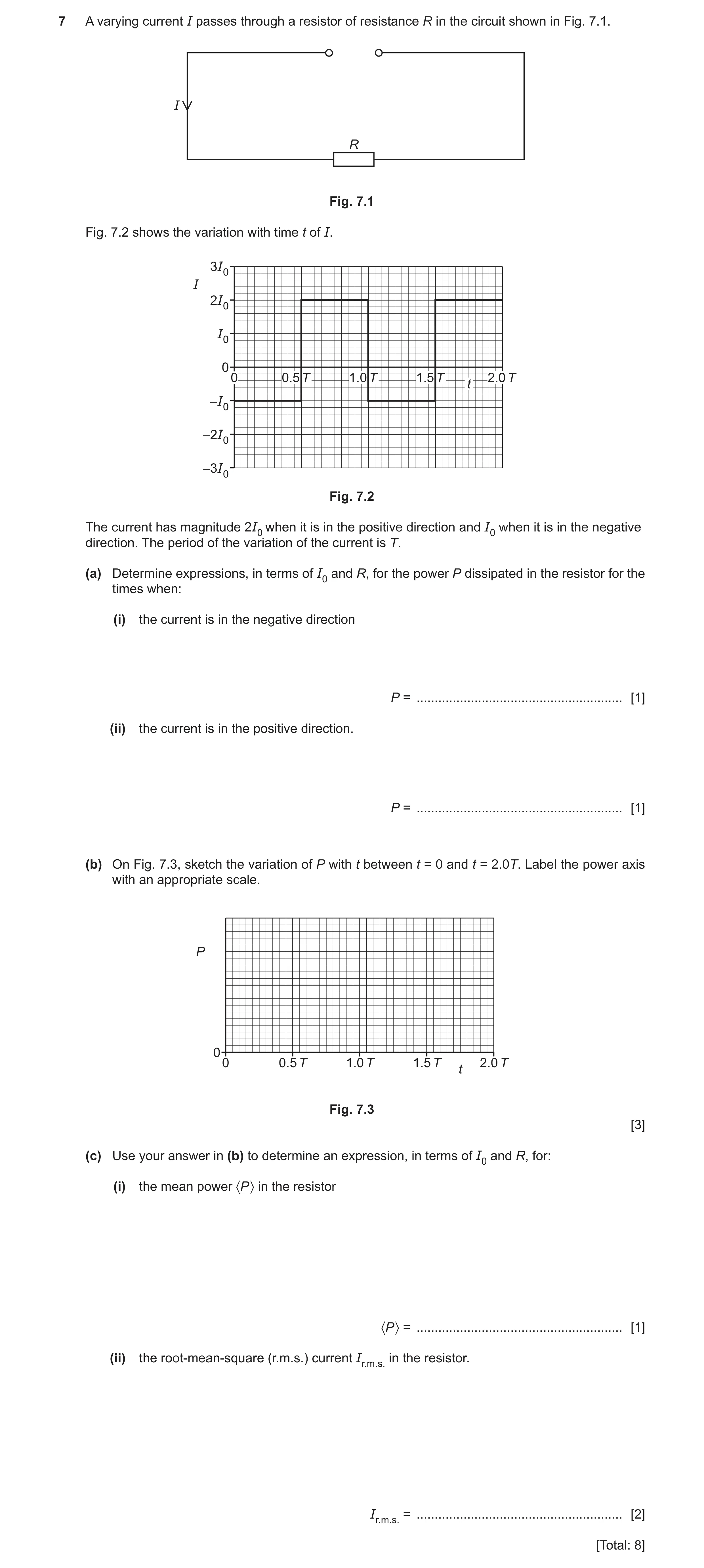
Q23 · A varying current I passes through a resistor of resistance R in the circuit shown in Fig 9702/41 Oct/Nov 2023
7 A varying current I passes through a resistor of resistance R in the circuit shown in Fig. 7.1. I R Fig. 7.1 Fig. 7.2 shows the variation with time t of I. 3I0 I 2I0 I0 0 0 0.5 T 1.0 T 1.5 T 2.0 T t –I0 –2I0 –3I0 Fig. 7.2 The current has magnitude 2I0 when it is in the positive direction and I0 when it is in the negative direction. The period of the variation of the current is T. (a) Determine expressions, in terms of I0 and R, for the power P dissipated in the resistor for the times when: (i) the current is in the negative direction P = … [1] (ii) the current is in the positive direction. P = … [1] (b) On Fig. 7.3, sketch the variation of P with t between t = 0 and t = 2.0T. Label the power axis with an appropriate scale. P 0 0 0.5 T 1.0 T 1.5 T 2.0 T t Fig. 7.3 [3] (c) Use your answer in (b) to determine an expression, in terms of I0 and R, for: (i) the mean power 〈P 〉 in the resistor 〈P 〉 = … [1] (ii) the root-mean-square (r.m.s.) current Ir.m.s. in the resistor. Ir.m.s. = … [2] [Total: 8]
8 marks
Mark scheme: 7(a)(i) P = I02R A1 7(a)(ii) P = 4I02R A1 7(b) sketch: square wave of period T, with P always non-zero B1 horizontal lines, from 0 to 0.5T and from 1.0T to 1.5T, all at the same level that the scale indicates to be I02R B1 horizontal lines, from 0.5T to 1.0T and from 1.5T to 2.0T, at a level that is four times higher than the lower lines B1 7(c)(i) <P> = (5/2)I02R A1 7(c)(ii) <P> = Ir.m.s.2R C1 Ir.m.s.2R = (5/2)I02R A1 Ir.m.s. = √(5/2) I0
This question in 9702/41 Oct/Nov 2023
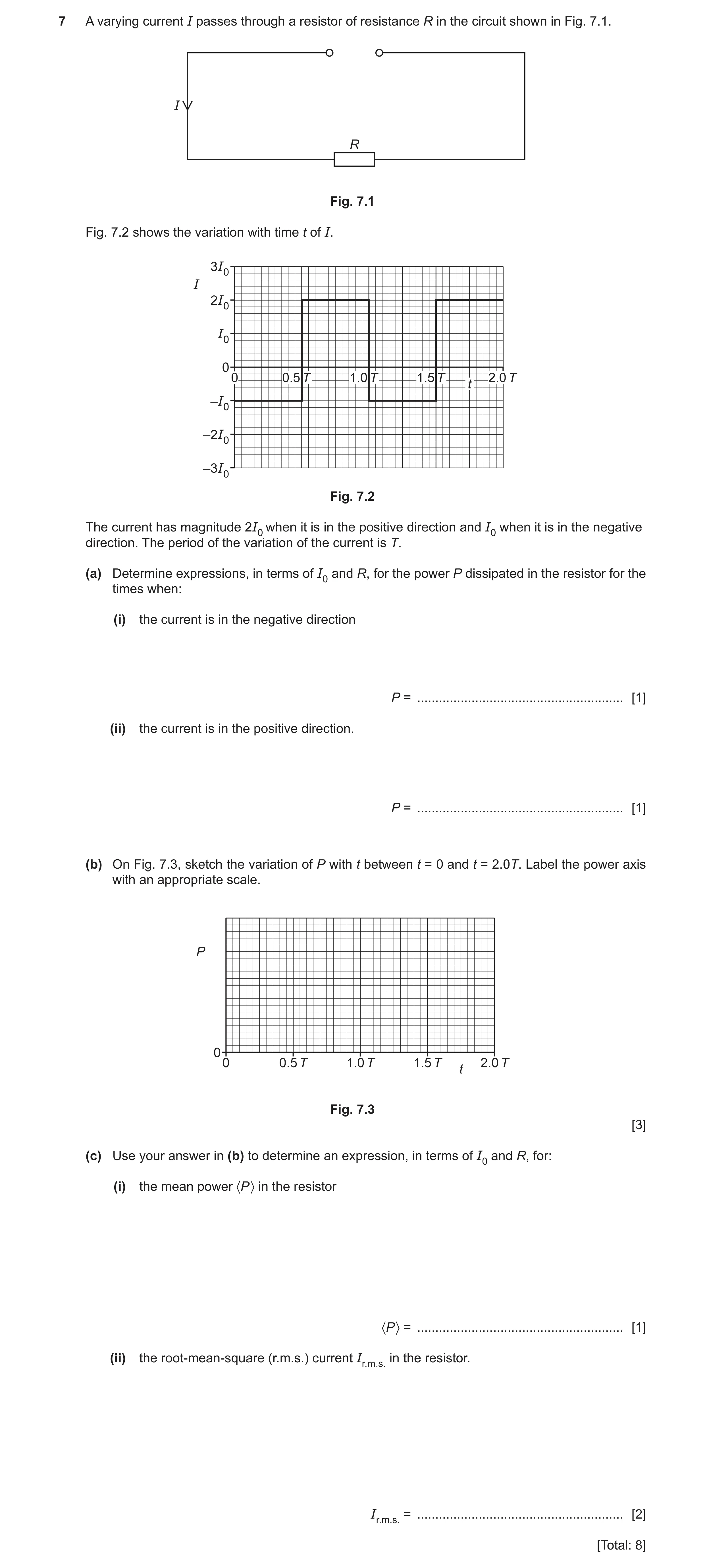
Q24 · A varying current I passes through a resistor of resistance R in the circuit shown in Fig 9702/43 Oct/Nov 2023
7 A varying current I passes through a resistor of resistance R in the circuit shown in Fig. 7.1. I R Fig. 7.1 Fig. 7.2 shows the variation with time t of I. 3I0 I 2I0 I0 0 0 0.5 T 1.0 T 1.5 T 2.0 T t –I0 –2I0 –3I0 Fig. 7.2 The current has magnitude 2I0 when it is in the positive direction and I0 when it is in the negative direction. The period of the variation of the current is T. (a) Determine expressions, in terms of I0 and R, for the power P dissipated in the resistor for the times when: (i) the current is in the negative direction P = … [1] (ii) the current is in the positive direction. P = … [1] (b) On Fig. 7.3, sketch the variation of P with t between t = 0 and t = 2.0T. Label the power axis with an appropriate scale. P 0 0 0.5 T 1.0 T 1.5 T 2.0 T t Fig. 7.3 [3] (c) Use your answer in (b) to determine an expression, in terms of I0 and R, for: (i) the mean power 〈P 〉 in the resistor 〈P 〉 = … [1] (ii) the root-mean-square (r.m.s.) current Ir.m.s. in the resistor. Ir.m.s. = … [2] [Total: 8]
8 marks
Mark scheme: 7(a)(i) P = I02R A1 7(a)(ii) P = 4I02R A1 7(b) sketch: square wave of period T, with P always non-zero B1 horizontal lines, from 0 to 0.5T and from 1.0T to 1.5T, all at the same level that the scale indicates to be I02R B1 horizontal lines, from 0.5T to 1.0T and from 1.5T to 2.0T, at a level that is four times higher than the lower lines B1 7(c)(i) <P> = (5/2)I02R A1 7(c)(ii) <P> = Ir.m.s.2R C1 Ir.m.s.2R = (5/2)I02R A1 Ir.m.s. = √(5/2) I0
This question in 9702/43 Oct/Nov 2023
Q25 · State what is meant by the frequency of an alternating current 9702/42 Oct/Nov 2024
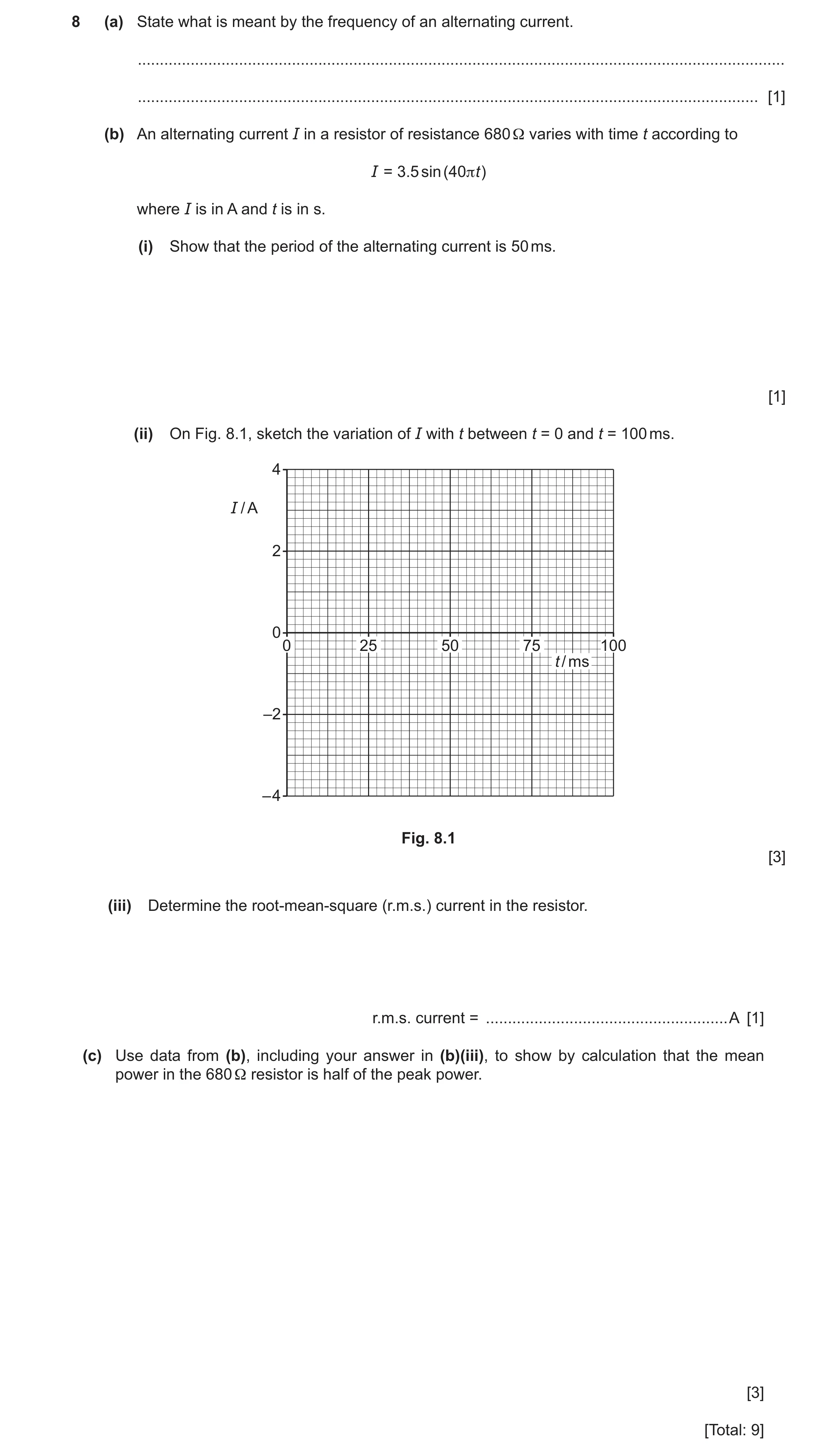
8 (a) State what is meant by the frequency of an alternating current. … … [1] (b) An alternating current I in a resistor of resistance 680 Ω varies with time t according to I = 3.5 sin (40πt) where I is in A and t is in s. (i) Show that the period of the alternating current is 50 ms. [1] (ii) On Fig. 8.1, sketch the variation of I with t between t = 0 and t = 100 ms. 4 I / A 2 0 0 25 50 75 100 t / ms –2 – 4 Fig. 8.1 [3] (iii) Determine the root‑mean‑square (r.m.s.) current in the resistor. r.m.s. current = … A [1] (c) Use data from (b), including your answer in (b)(iii), to show by calculation that the mean power in the 680 Ω resistor is half of the peak power. [3] [Total: 9]
9 marks
Mark scheme: 8(a) number of cycles per unit time B1 8(b)(i) period = 2 / 40 = 0.050 s = 50 ms A1 8(b)(ii) sinusoidal curve, starting at (0, 0) and initially increasing from there B1 periodic line showing 2 cycles with period 50 ms from t = 0 to t = 100 ms B1 all peaks shown at I = +3.5 A and all troughs shown at I = –3.5 A B1 8(b)(iii) Ir.m.s = 3.5 / √2 A1 = 2.5 A 8(c) P = I2R C1 peak power = 3.52 680 (= 8330 W) M1 or mean power = 2.472 680 (= 4170 W) peak and mean powers both calculated correctly, with supporting working, and compared leading to conclusion that mean A1 power is half the peak power
This question in 9702/42 Oct/Nov 2024
Q26 · A circuit that produces rectification of an alternating input voltage 9702/42 May/June 2025
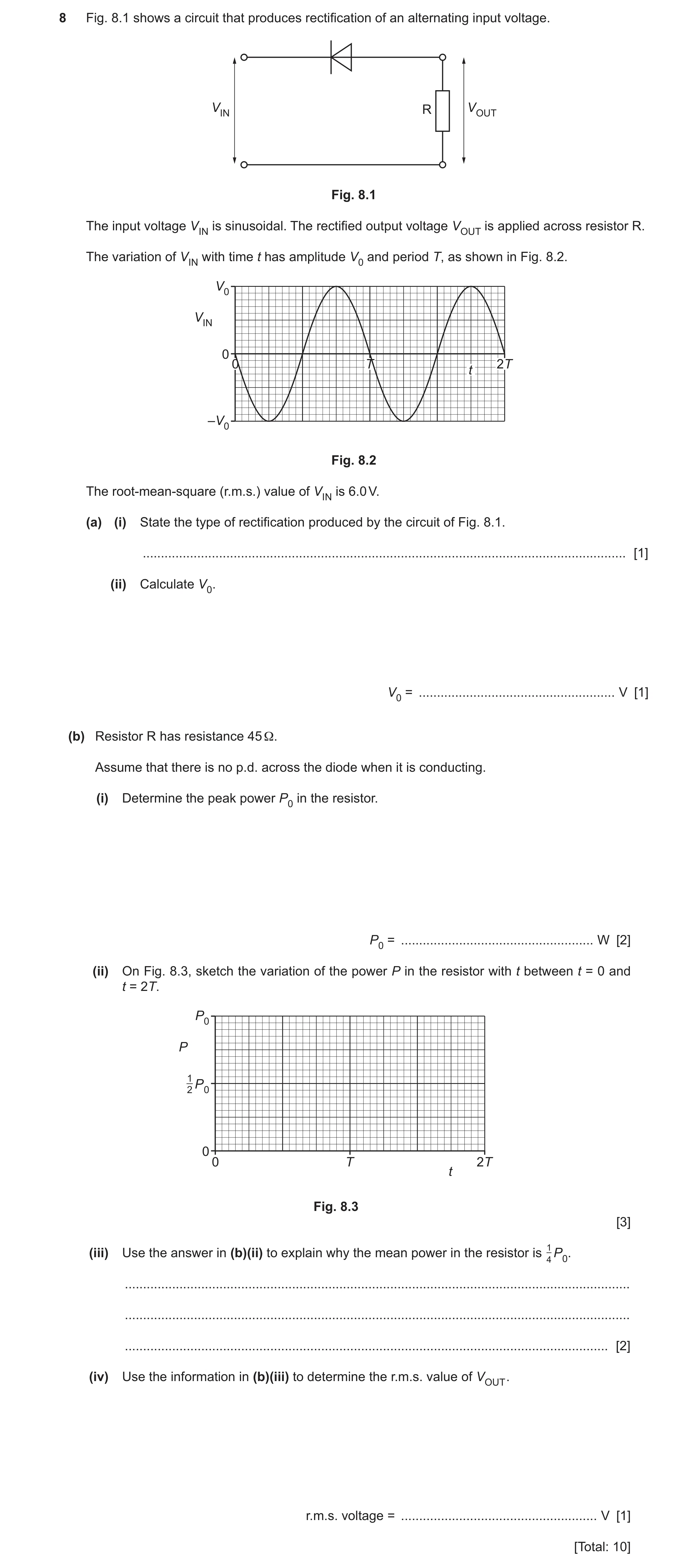
8 Fig. 8.1 shows a circuit that produces rectification of an alternating input voltage. VIN R VOUT Fig. 8.1 The input voltage VIN is sinusoidal. The rectified output voltage VOUT is applied across resistor R. The variation of VIN with time t has amplitude V0 and period T, as shown in Fig. 8.2. V0 VIN 0 0 T 2T t –V0 Fig. 8.2 The root-mean-square (r.m.s.) value of VIN is 6.0 V. (a) (i) State the type of rectification produced by the circuit of Fig. 8.1. … [1] (ii) Calculate V0. V0 = … V [1] (b) Resistor R has resistance 45 Ω. Assume that there is no p.d. across the diode when it is conducting. (i) Determine the peak power P0 in the resistor. P0 = … W [2] (ii) On Fig. 8.3, sketch the variation of the power P in the resistor with t between t = 0 and t = 2T. P0 P 1 2 P0 0 0 T 2T t Fig. 8.3 [3] (iii) Use the answer in (b)(ii) to explain why the mean power in the resistor is 14 P0. … … … [2] (iv) Use the information in (b)(iii) to determine the r.m.s. value of VOUT . r.m.s. voltage = … V [1] [Total: 10]
10 marks
Mark scheme: 8(a)(i) half-wave (rectification) B1 8(a)(ii) A1 V0 = 6.0 × 2 = 8.5 V 8(b)(i) P = V2 / R C1 P0 = 8.52 / 45 A1 = 1.6 W 8(b)(ii) two humps of width 0.5T and two sections of zero power of width 0.5T B1 all humps drawn have width 0.5T, minima at P = 0 and peaks at P = P0 B1 correct sinusoidal shape, with smooth troughs sitting on t-axis at P = 0 B1 8(b)(iii) 1 B1 mean power within each hump is P0 from the symmetry of the curve 2 additional half factor from removal of half of the power in each cycle B1 8(b)(iv) 〈P〉 = Vr.m.s.2 / R A1 Vr.m.s. = ( 1.6 / 4 ) 45 = 4.2 V
This question in 9702/42 May/June 2025
Q27 · An alternating voltage V varies with time t according to V = 18 cos 40 πt where V is in V… 9702/42 Oct/Nov 2025
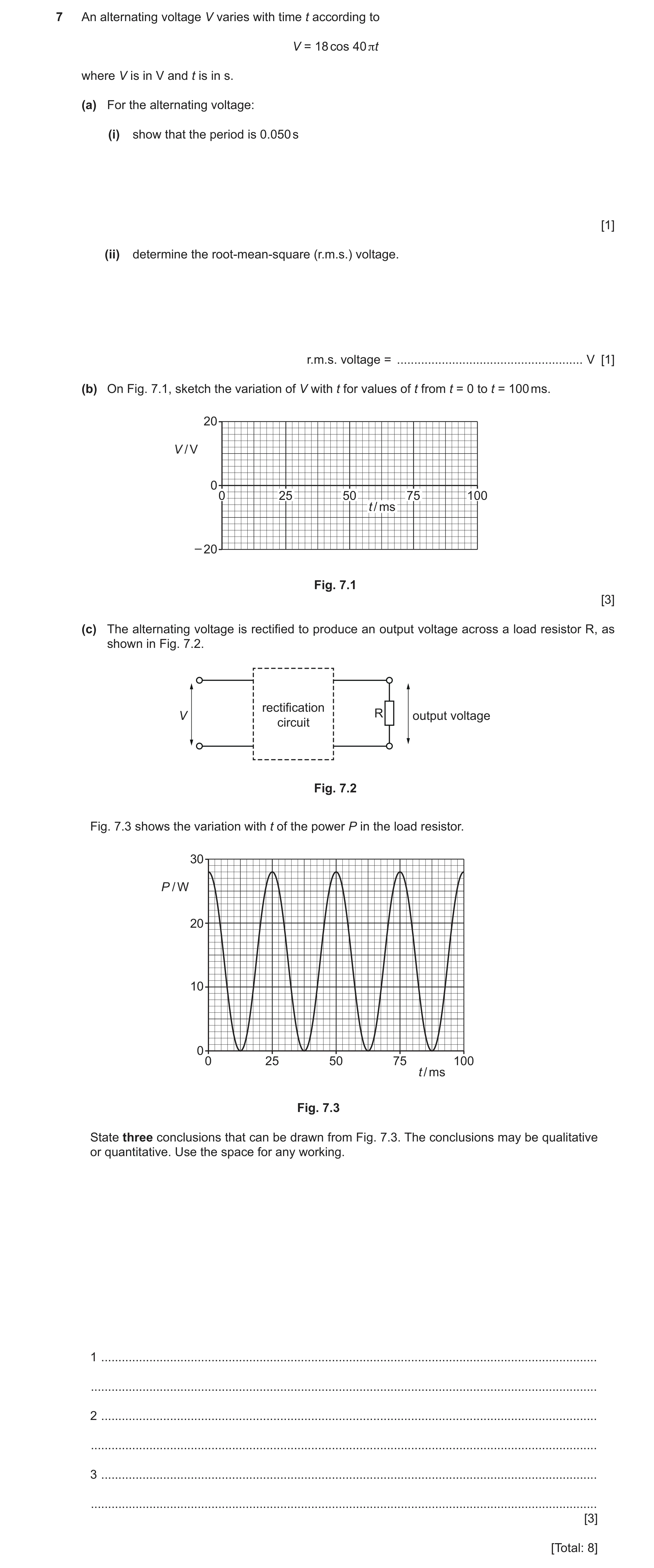
7 An alternating voltage V varies with time t according to V = 18 cos 40 πt where V is in V and t is in s. (a) For the alternating voltage: (i) show that the period is 0.050 s [1] (ii) determine the root-mean-square (r.m.s.) voltage. r.m.s. voltage = … V [1] (b) On Fig. 7.1, sketch the variation of V with t for values of t from t = 0 to t = 100 ms. 20 V / V 0 0 25 50 75 100 t / ms – 20 Fig. 7.1 [3] (c) The alternating voltage is rectified to produce an output voltage across a load resistor R, as shown in Fig. 7.2. rectification V R output voltage circuit Fig. 7.2 Fig. 7.3 shows the variation with t of the power P in the load resistor. 30 P / W 20 10 0 0 25 50 75 100 t / ms Fig. 7.3 State three conclusions that can be drawn from Fig. 7.3. The conclusions may be qualitative or quantitative. Use the space for any working. 1 … … 2 … … 3 … … [3] [Total: 8]
8 marks
Mark scheme: 7(a)(i) T = 2 / 40 = 0.050 s A1 7(a)(ii) Vr.m.s. = 18 / √2 A1 = 13 V 7(b) sinusoidal curve of period 50 ms from t = 0 to t = 100 ms B1 correct phase (VMAX at t = 0, 50, 100 ms and –VMAX at 25, 75 ms etc.) B1 maximum and minimum voltages shown as 18 V B1 7(c) Any three points from: B3 • rectification is full-wave • mean power = 14 W • resistance of R = 12 • peak current in R = 1.6 A or r.m.s. current in R = 1.1 A • period of output voltage / power = 25 ms or frequency of output voltage / power = 40 Hz or angular frequency of output voltage / power = 250 rad s–1
This question in 9702/42 Oct/Nov 2025
 1 / 39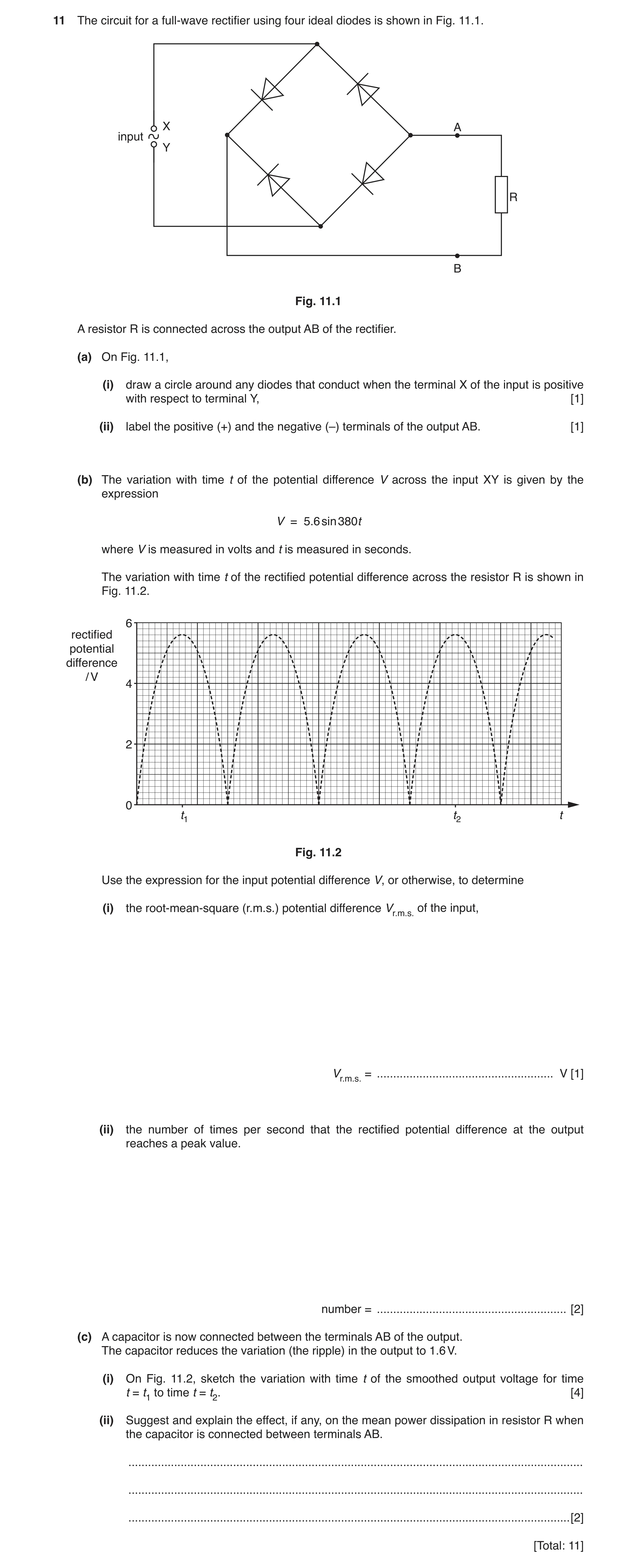
 3 / 39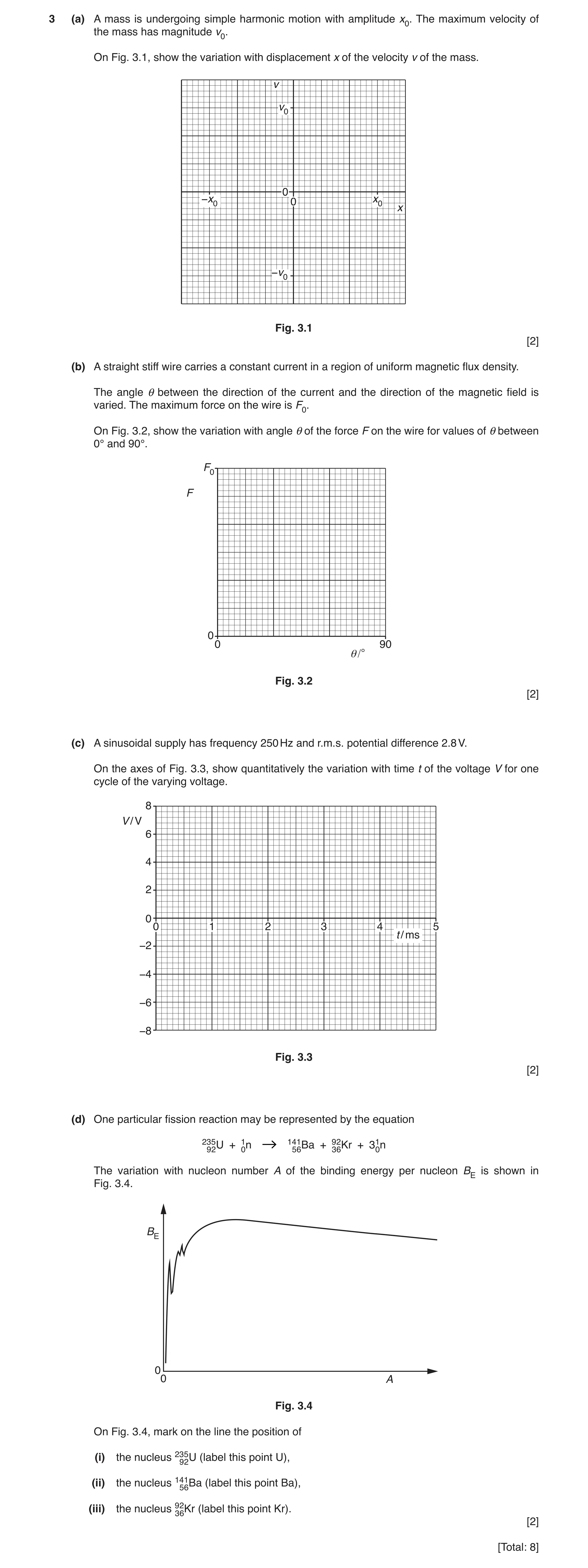
 16 / 39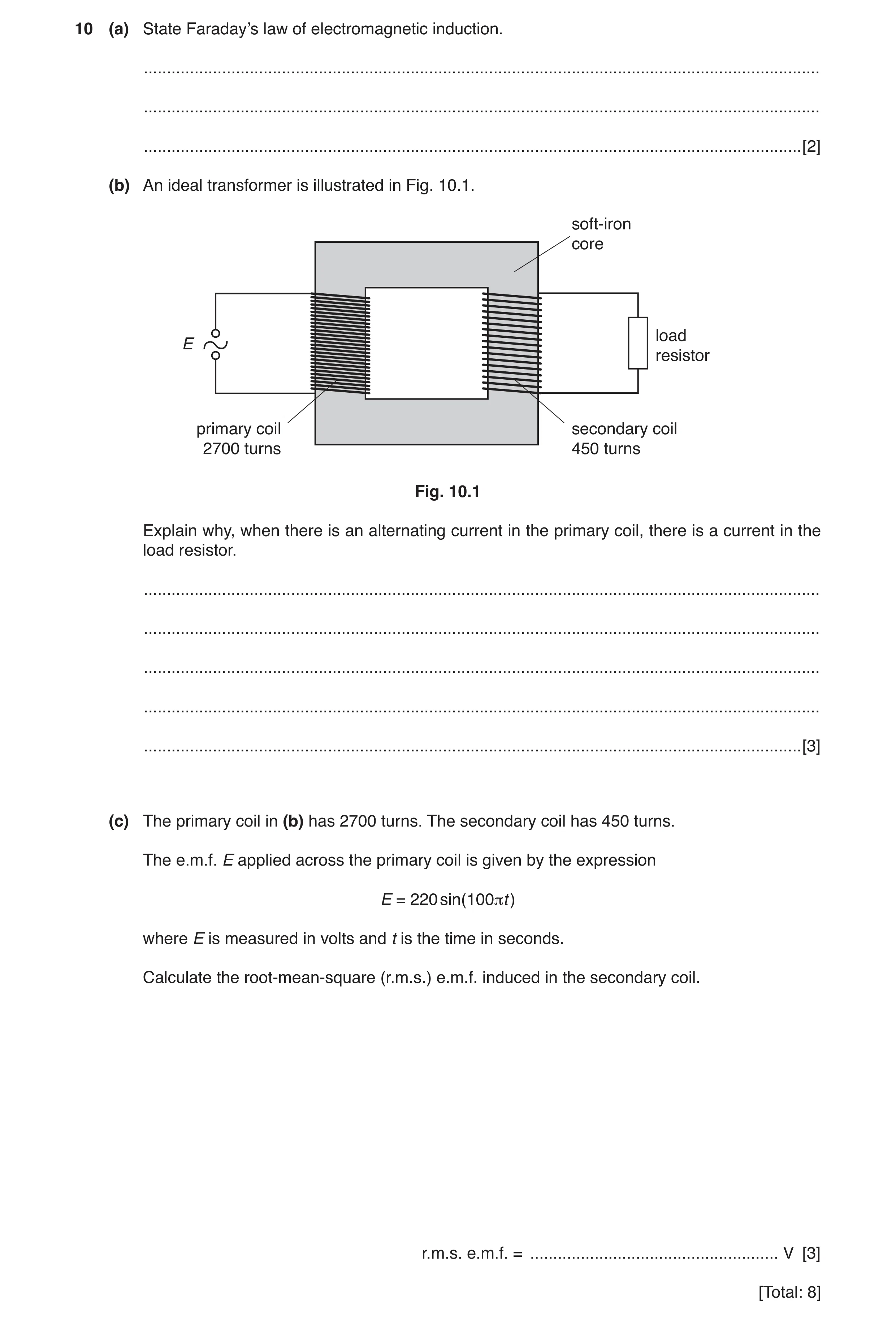
 19 / 39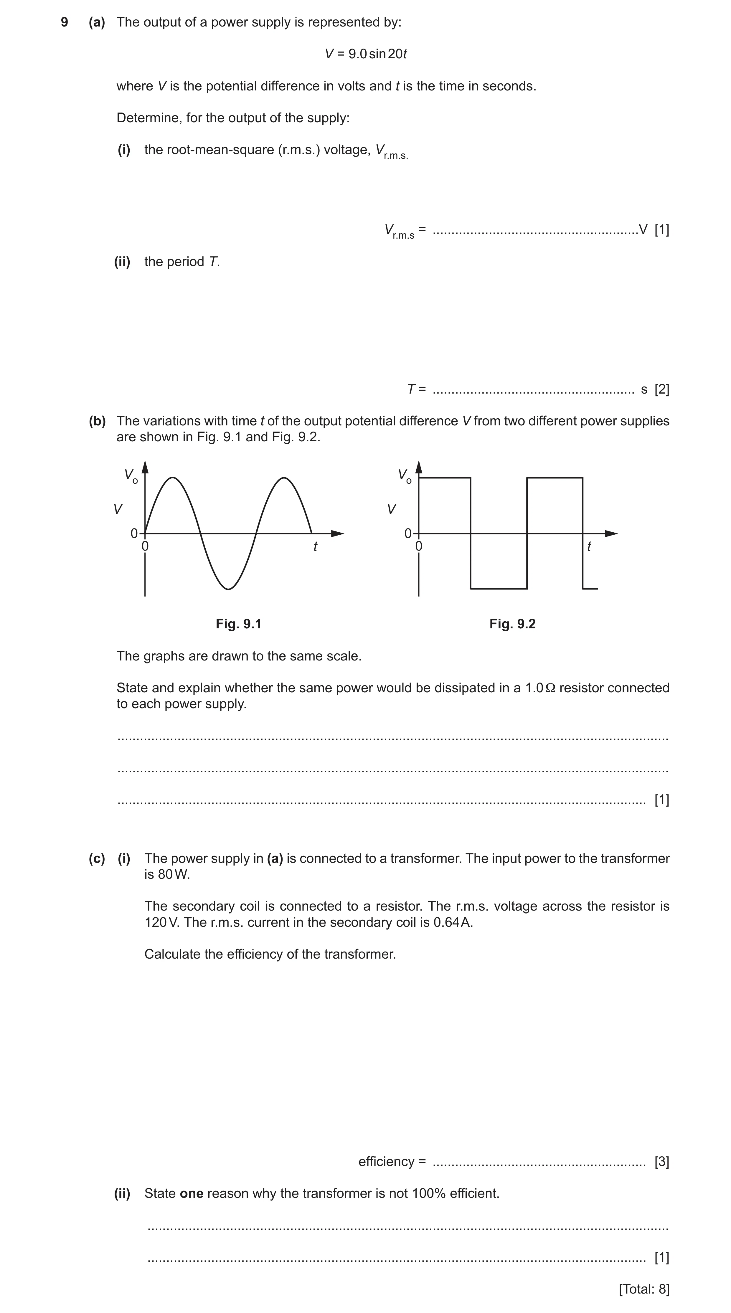
 28 / 39
 29 / 39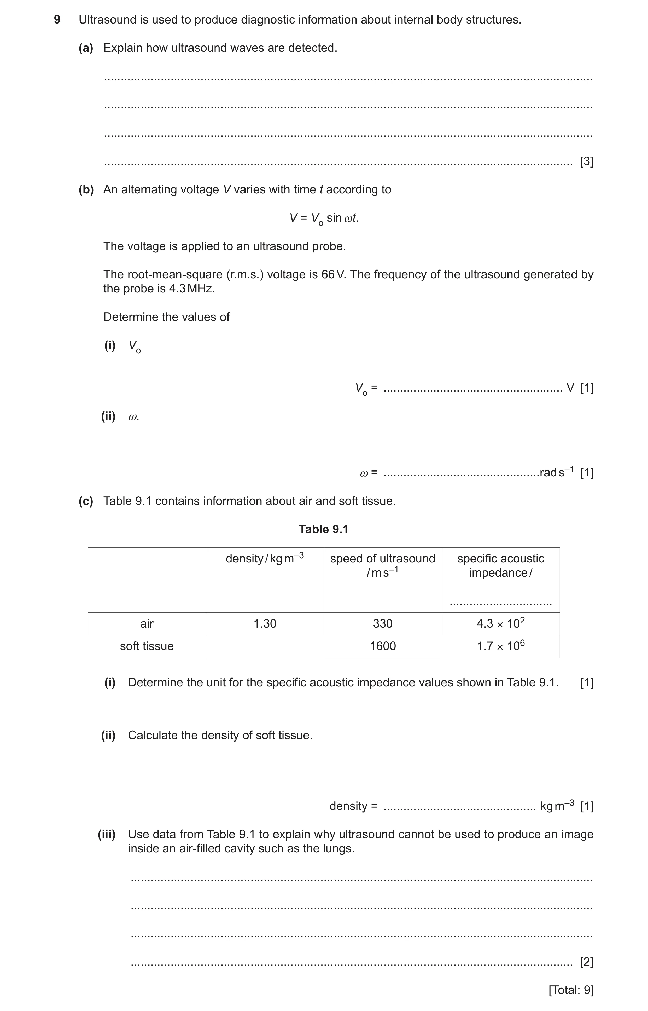
 6
6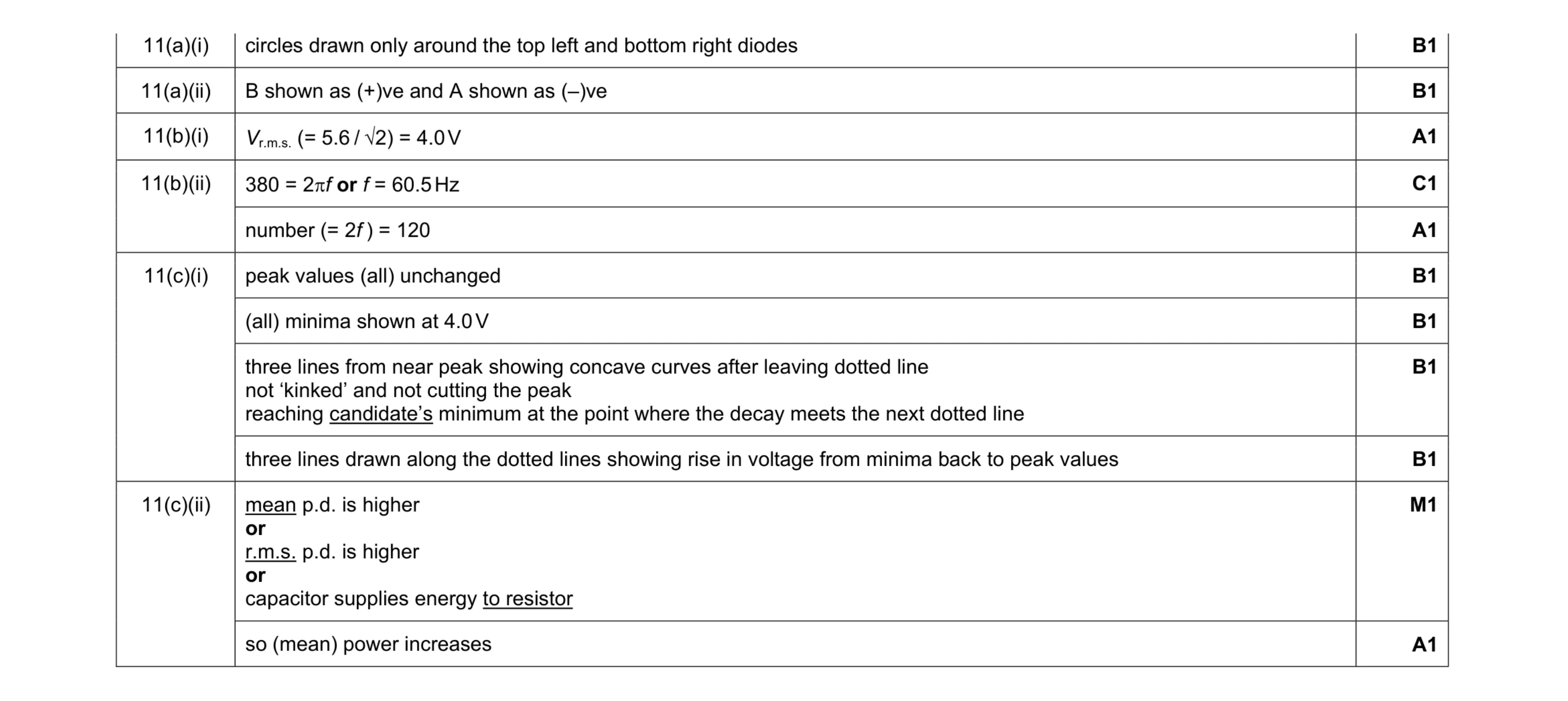 11
11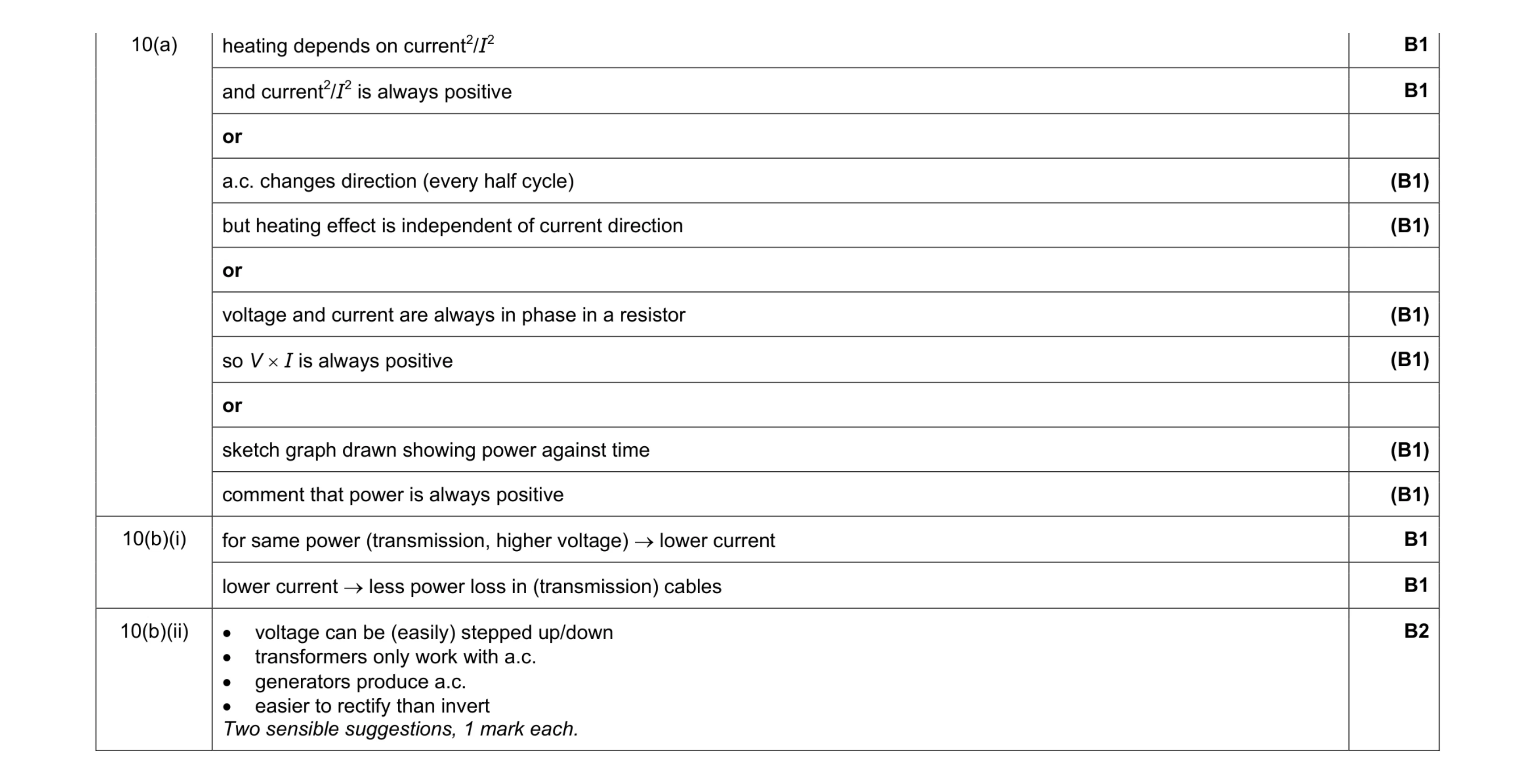 6
6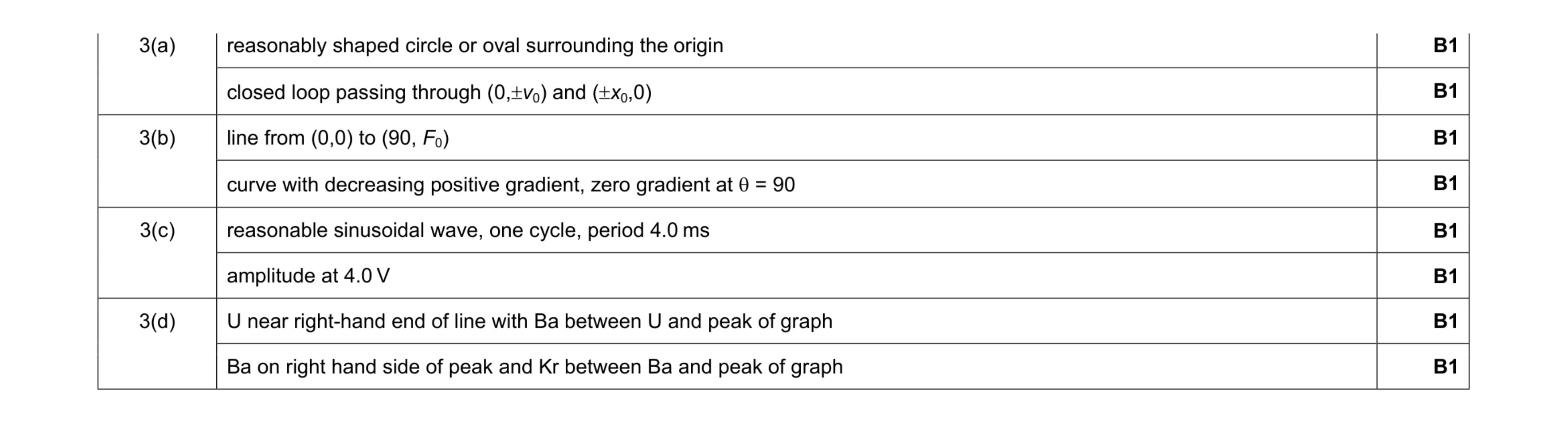 8
8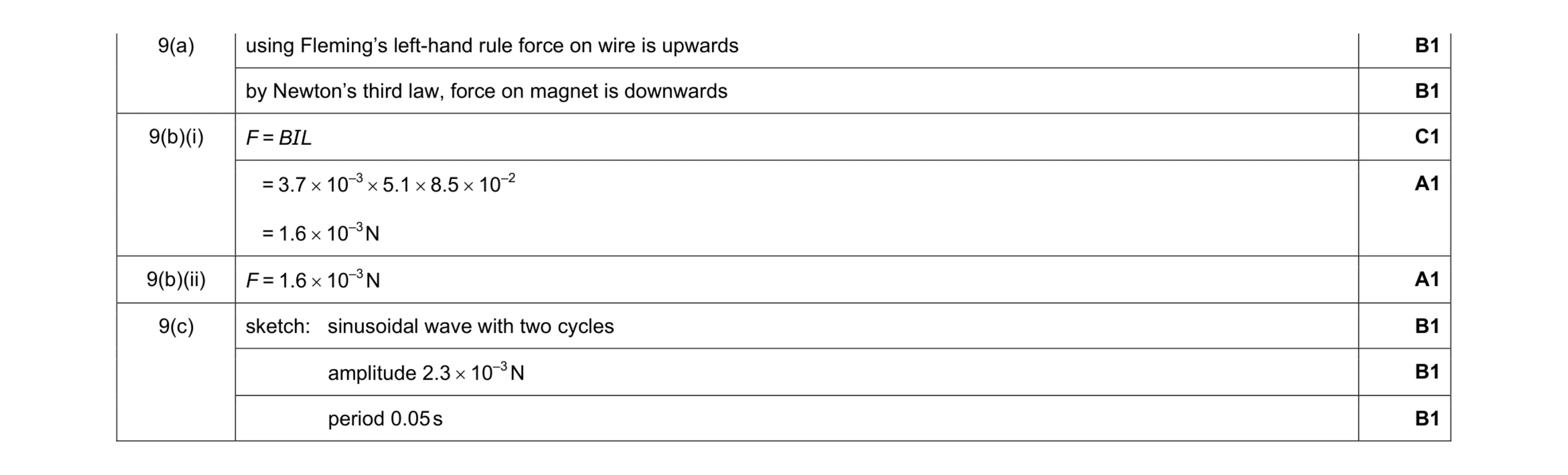 8
8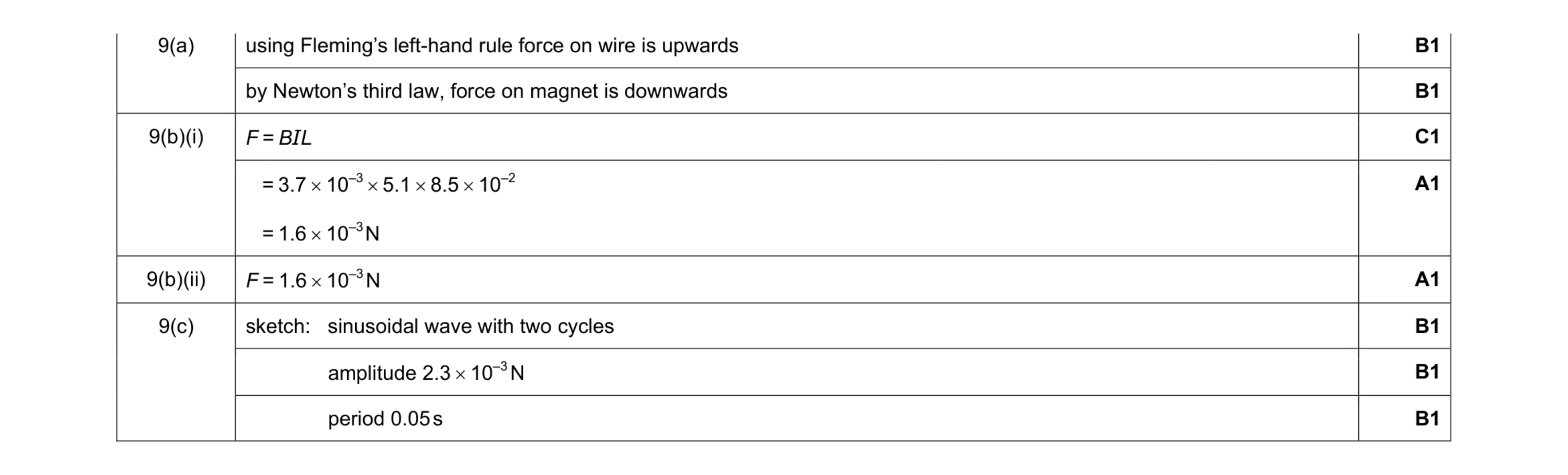 8
8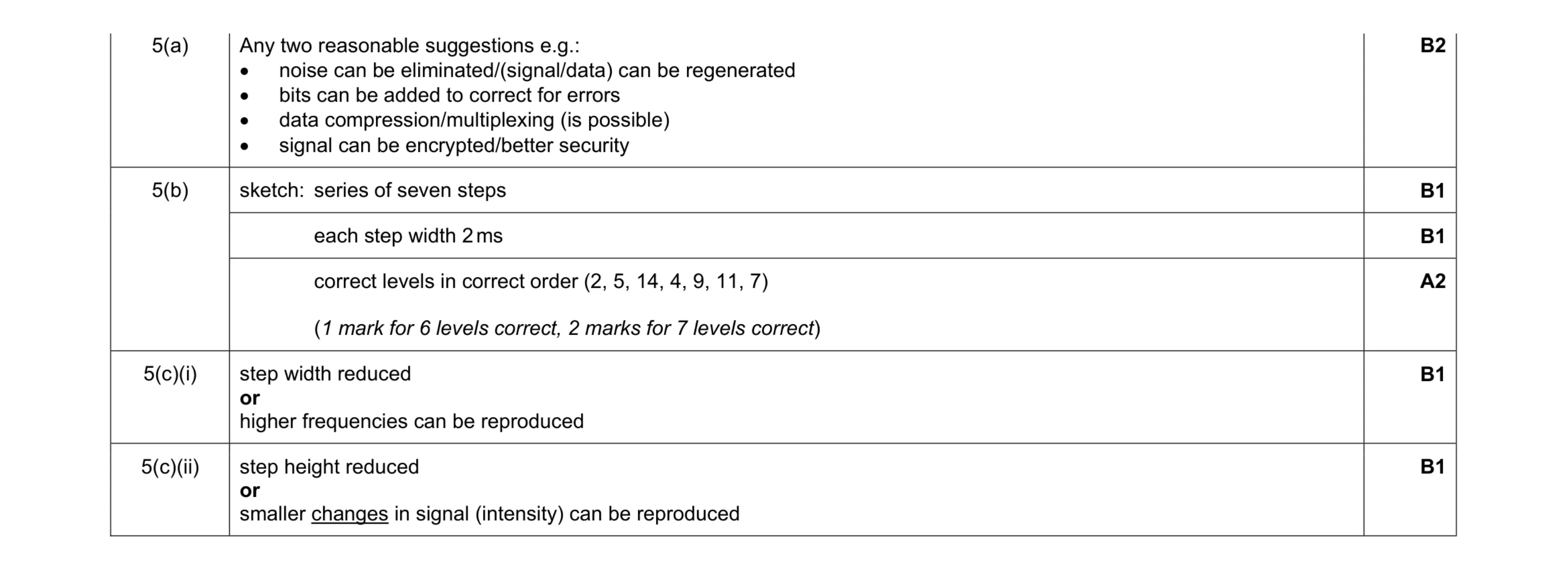 8
8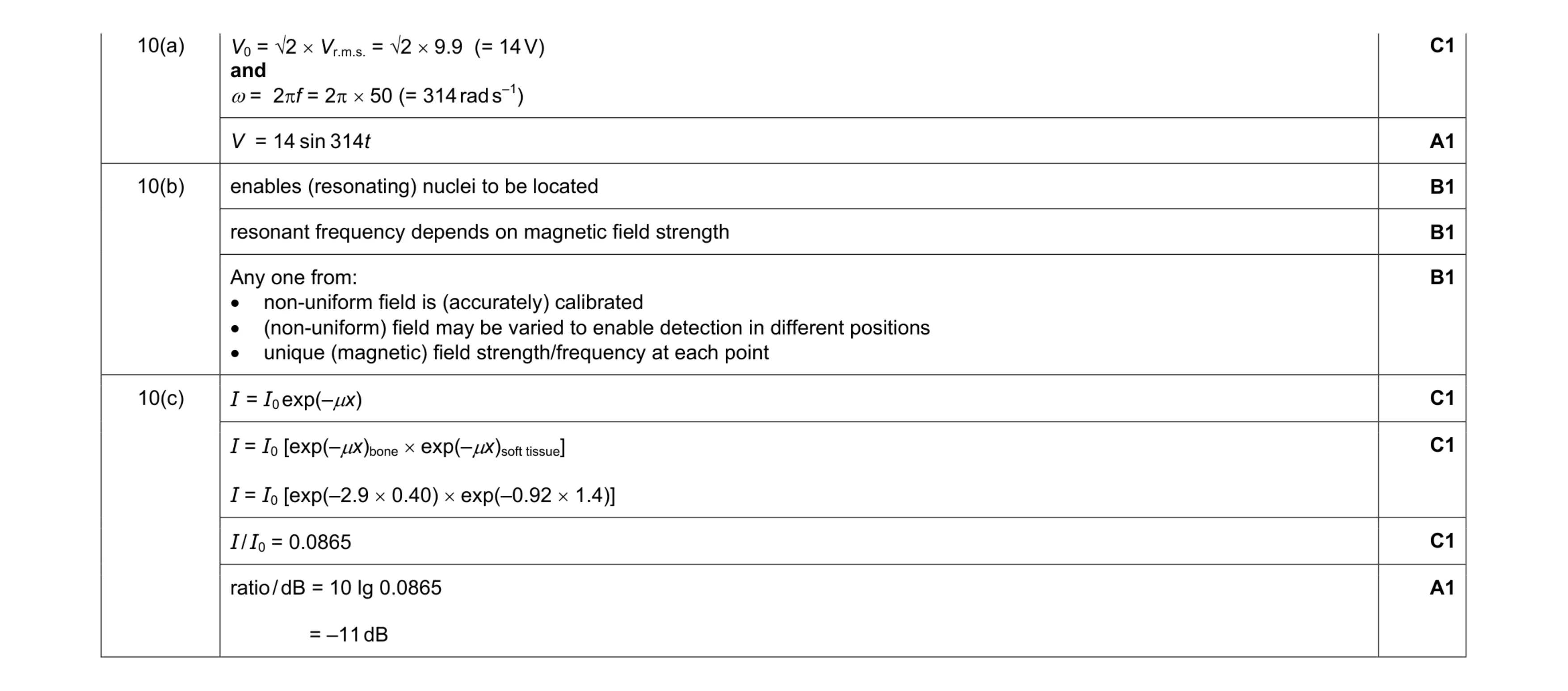 9
9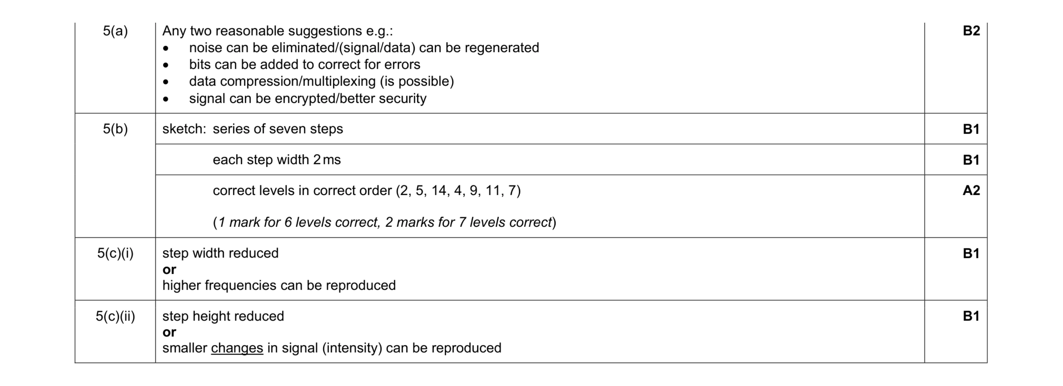 8
8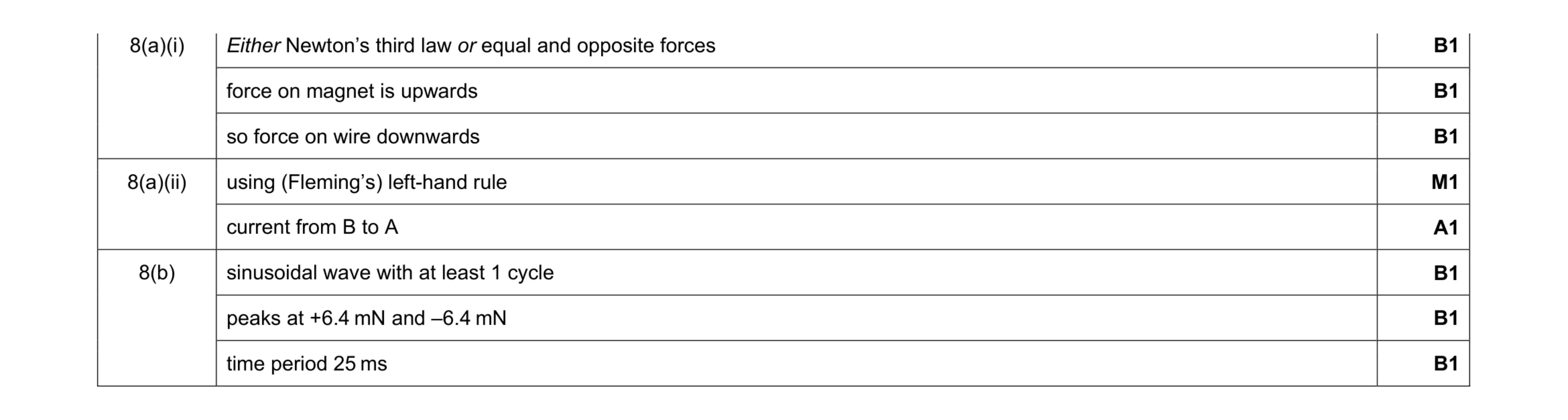 8
8 4
4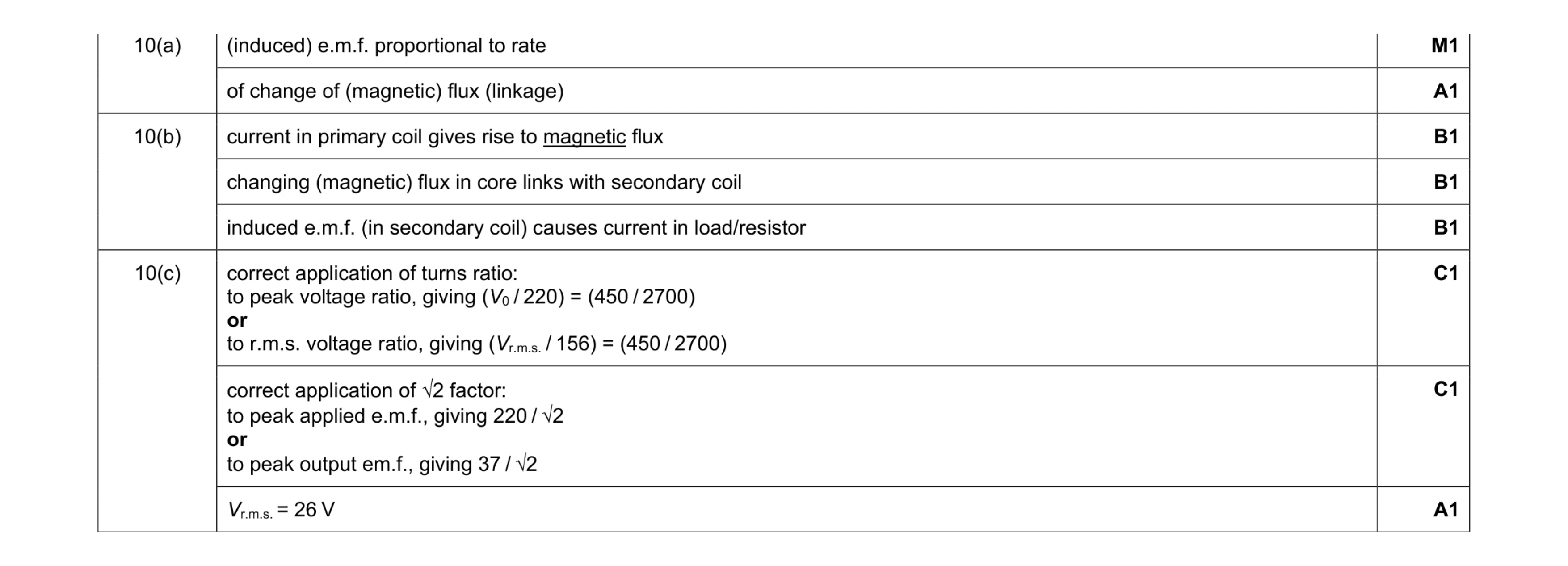 8
8 4
4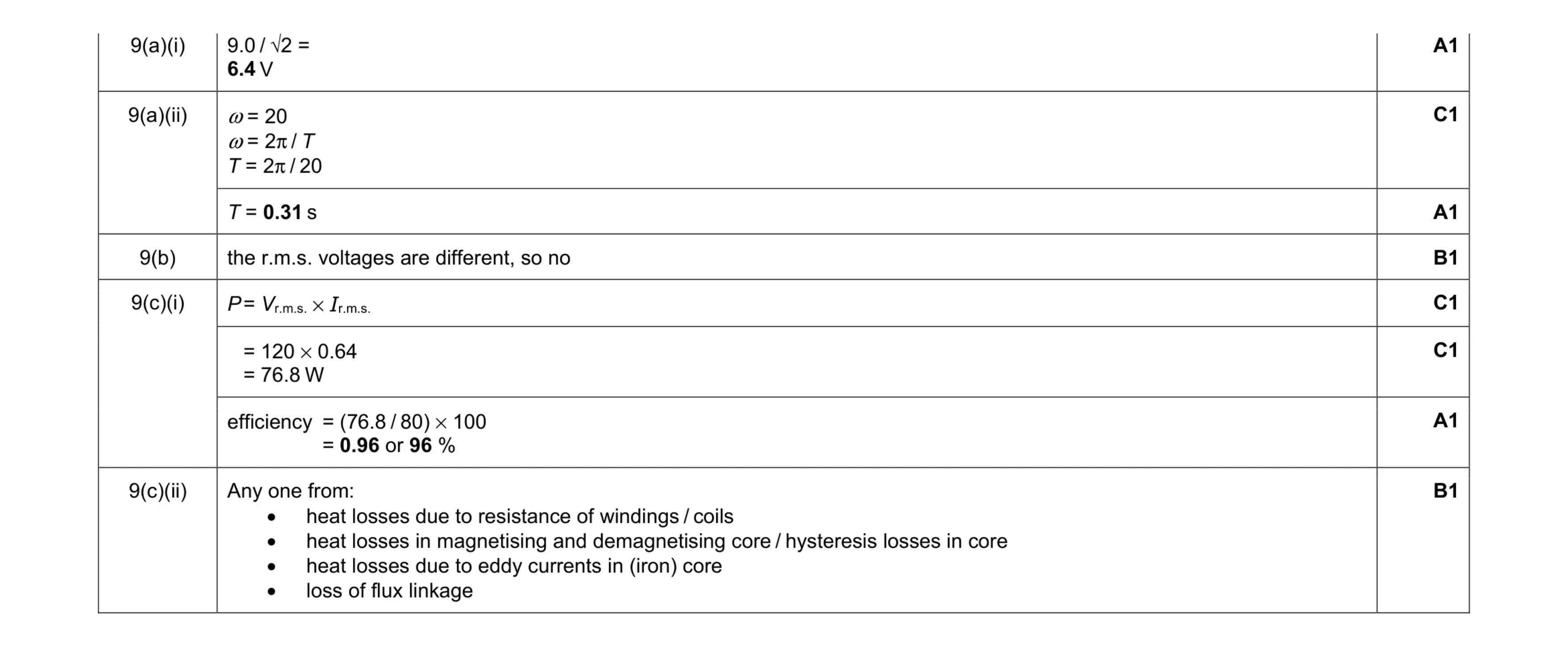 8
8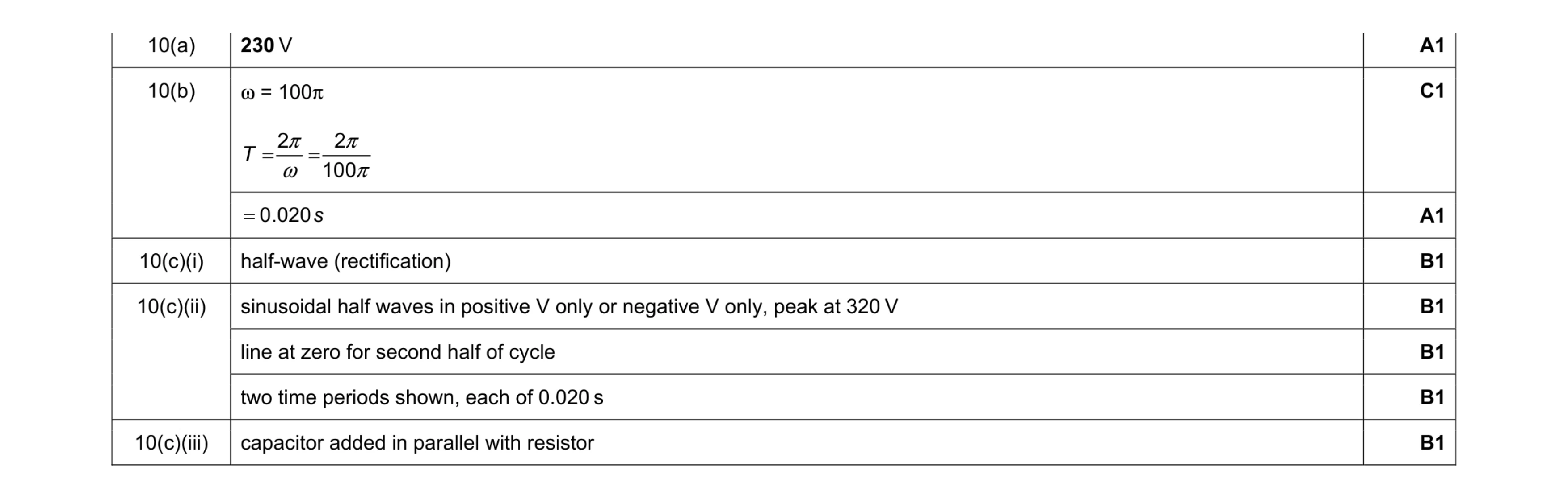 8
8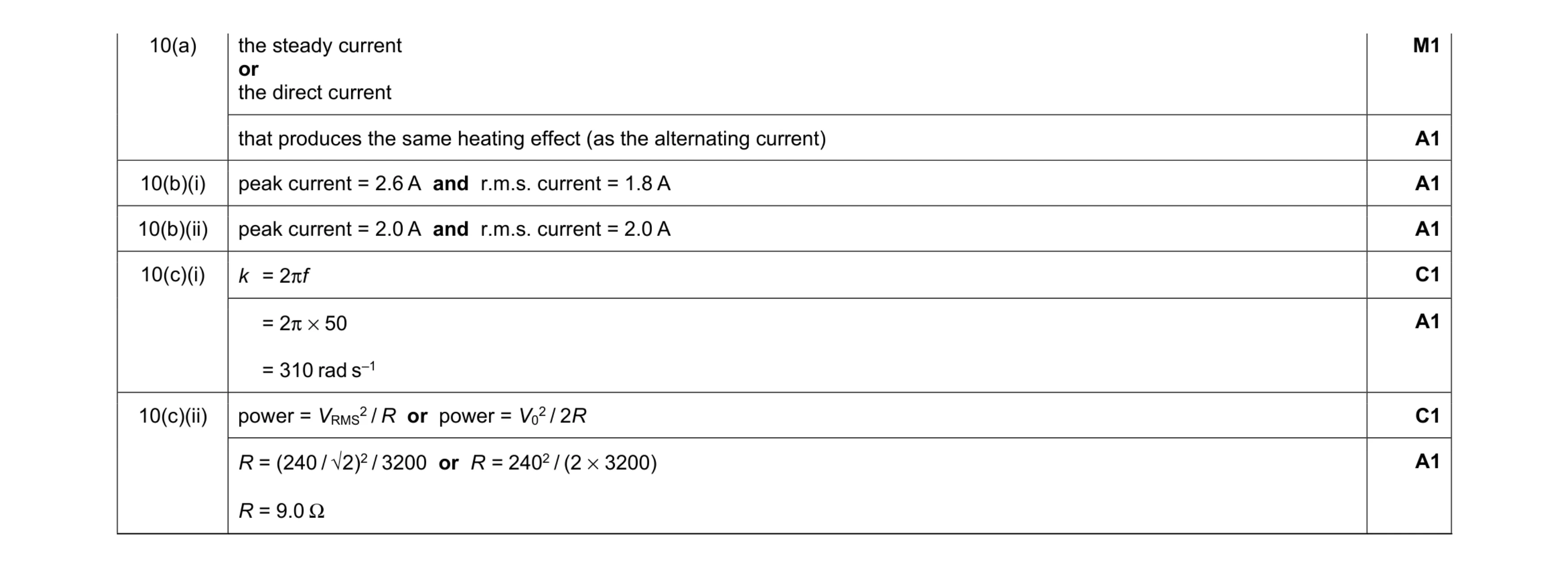 8
8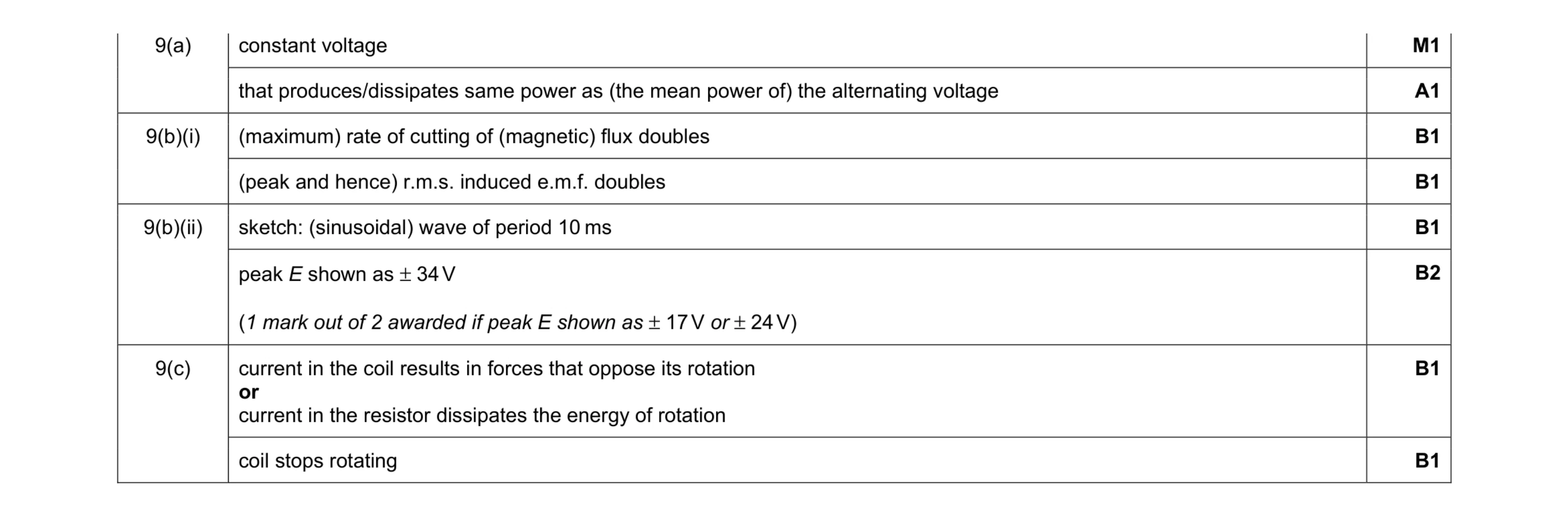 9
9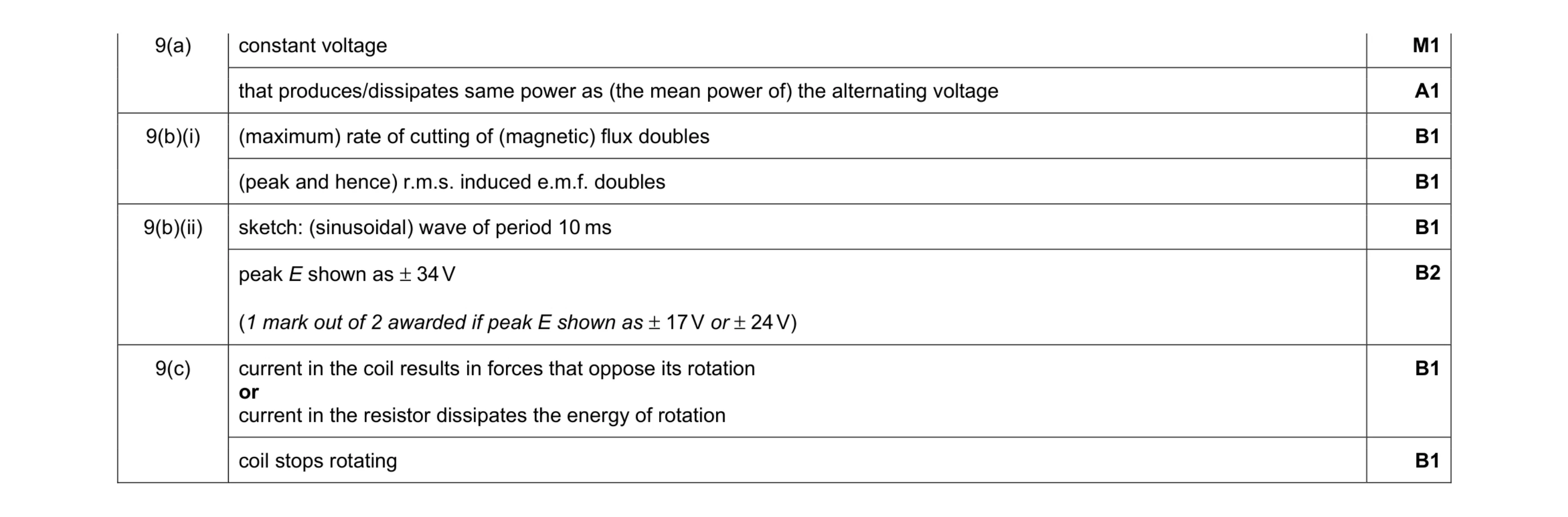 9
9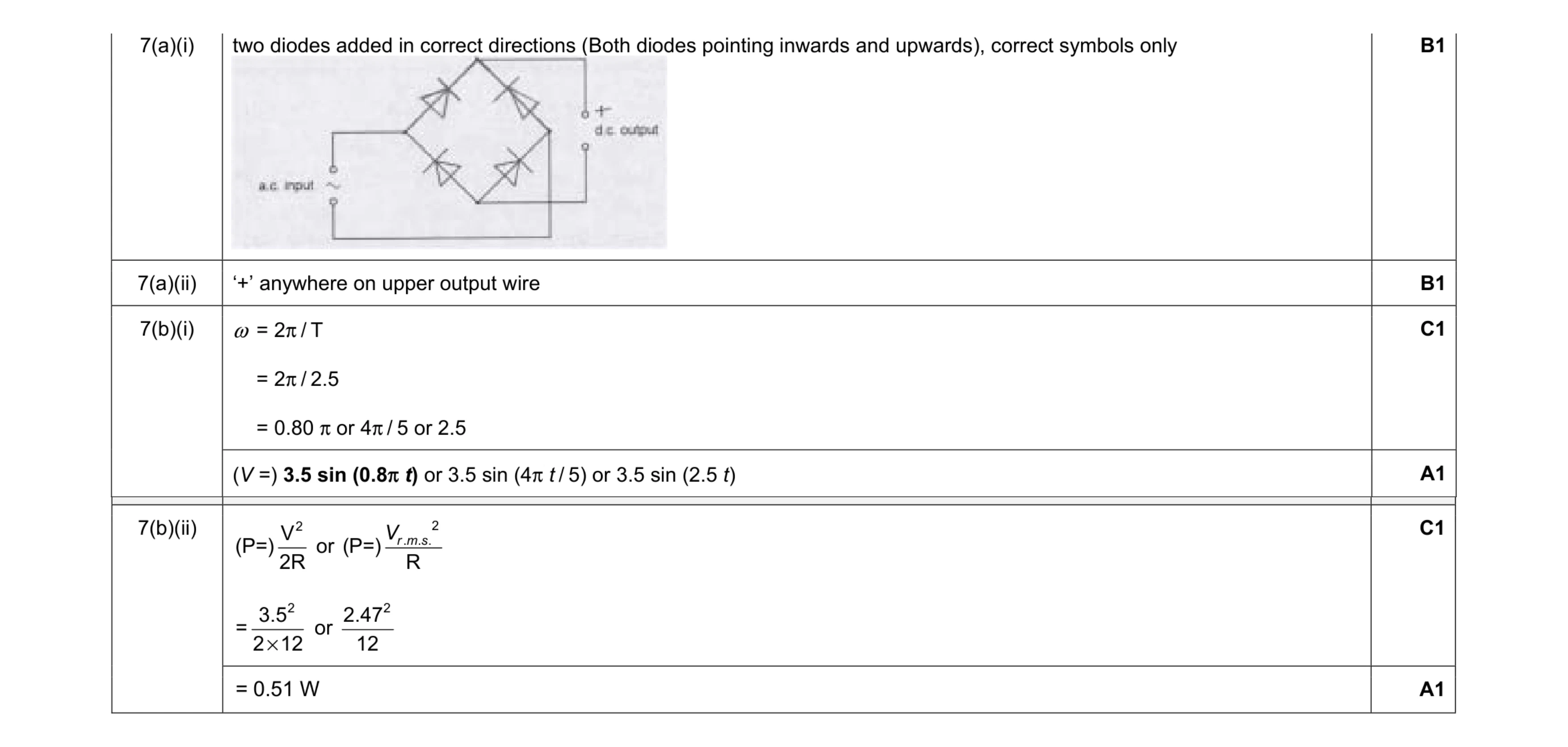 6
6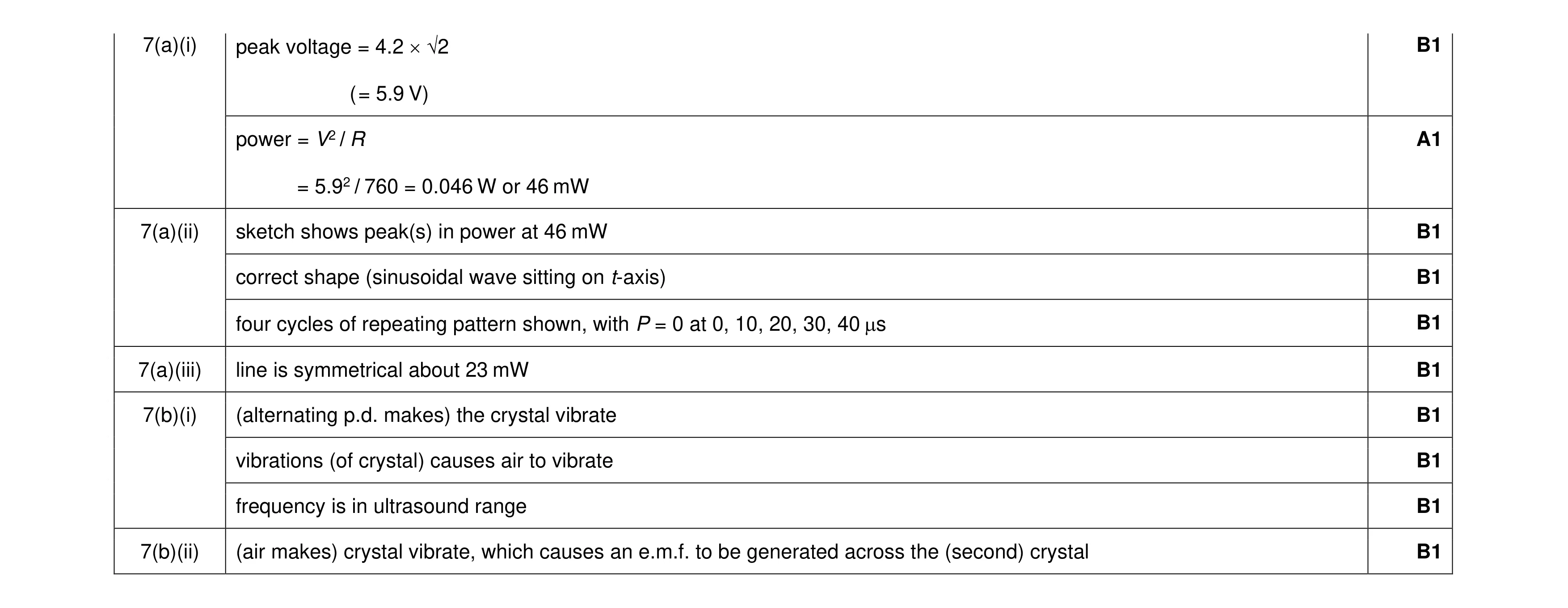 10
10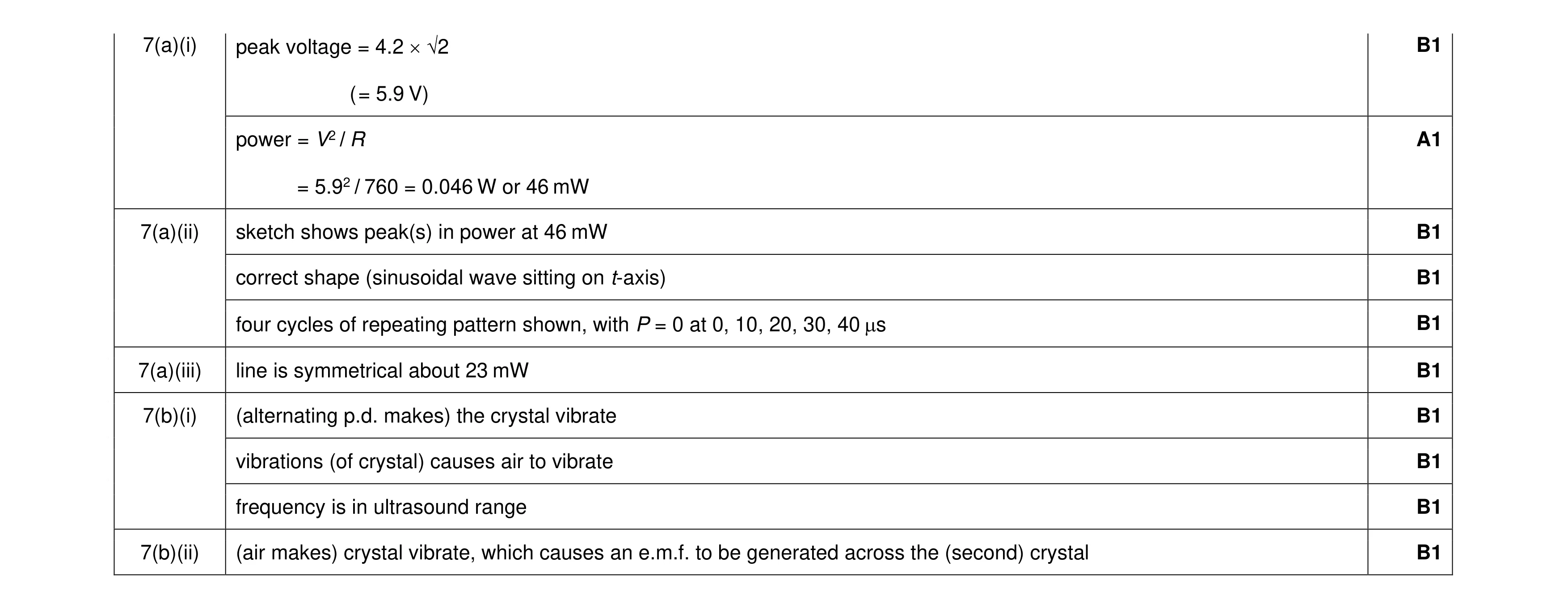 10
10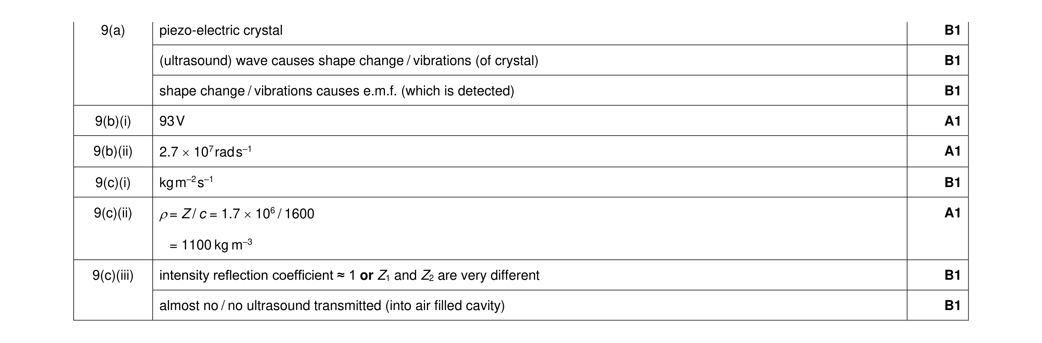 9
9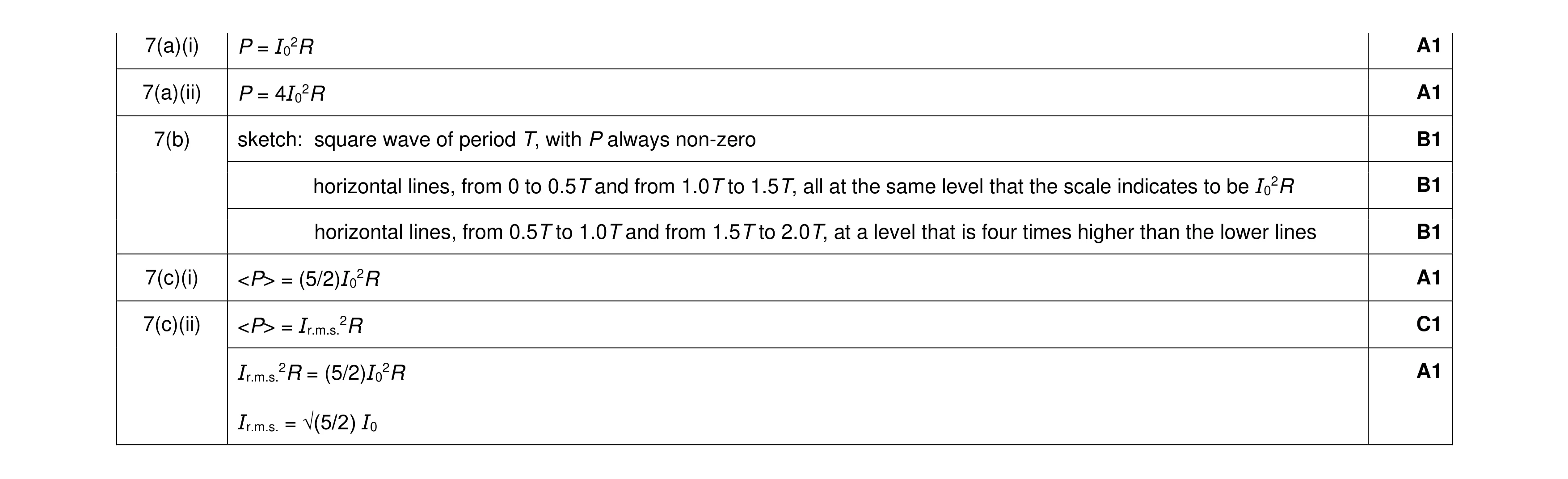 8
8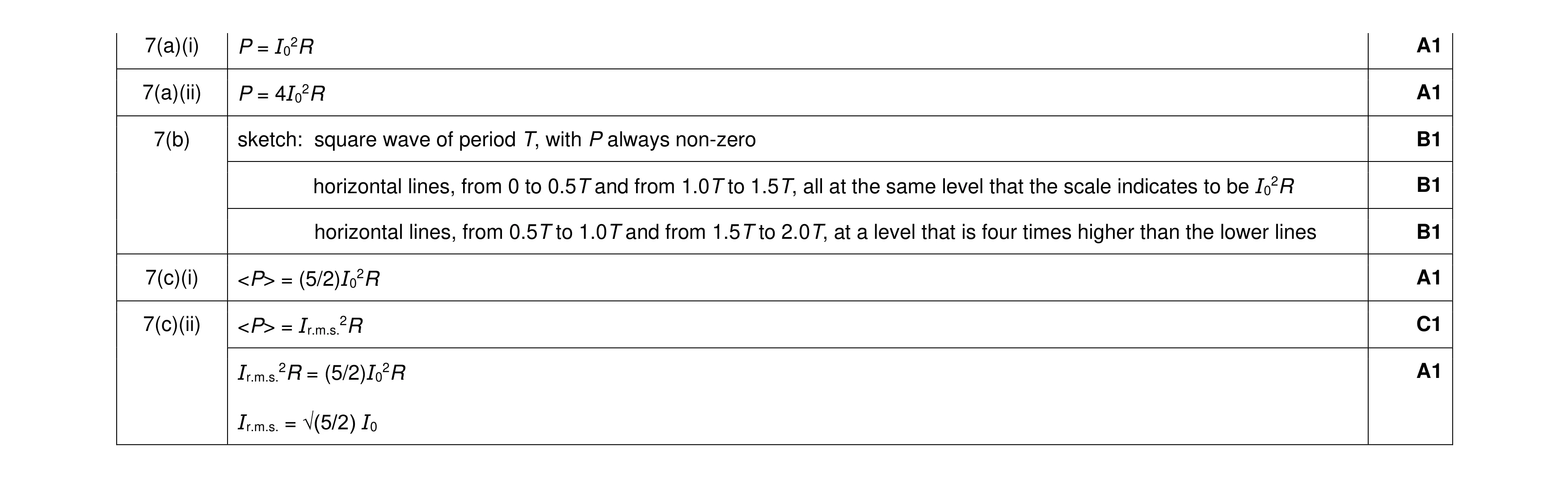 8
8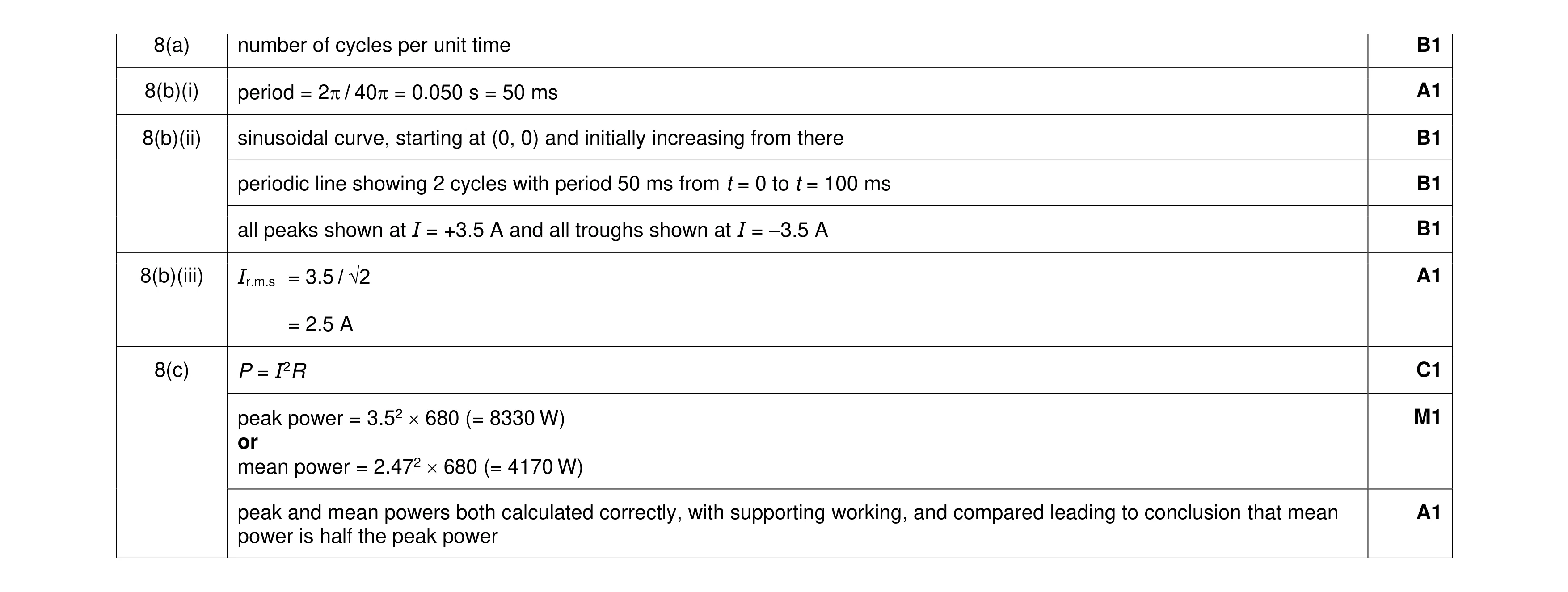 9
9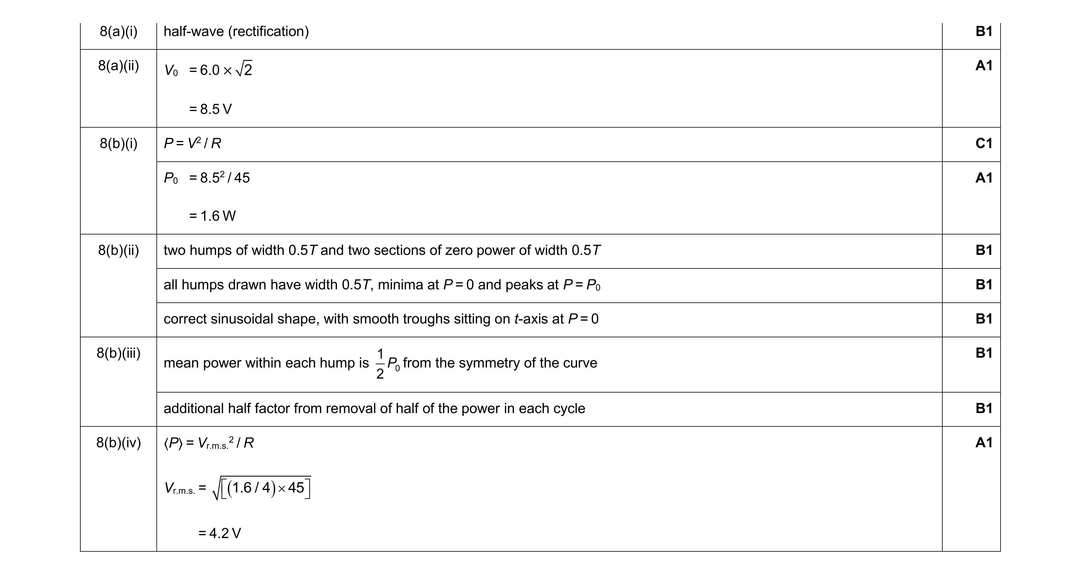 10
10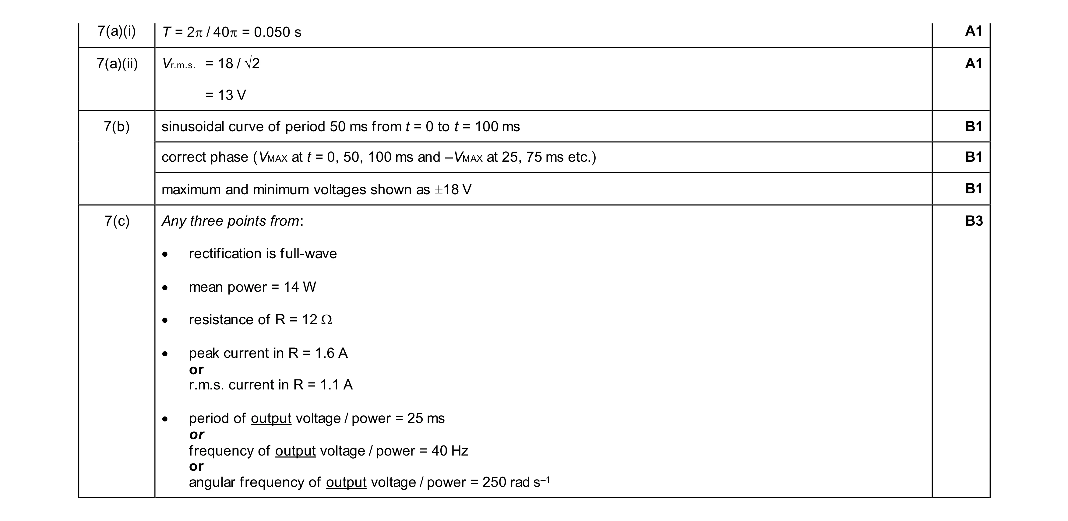 8
8