Questions as text
Q1 · State (i) what is meant by the hardness of an X-ray beam, … … … [2] (ii) how the hardness… 9702/41 May/June 2017
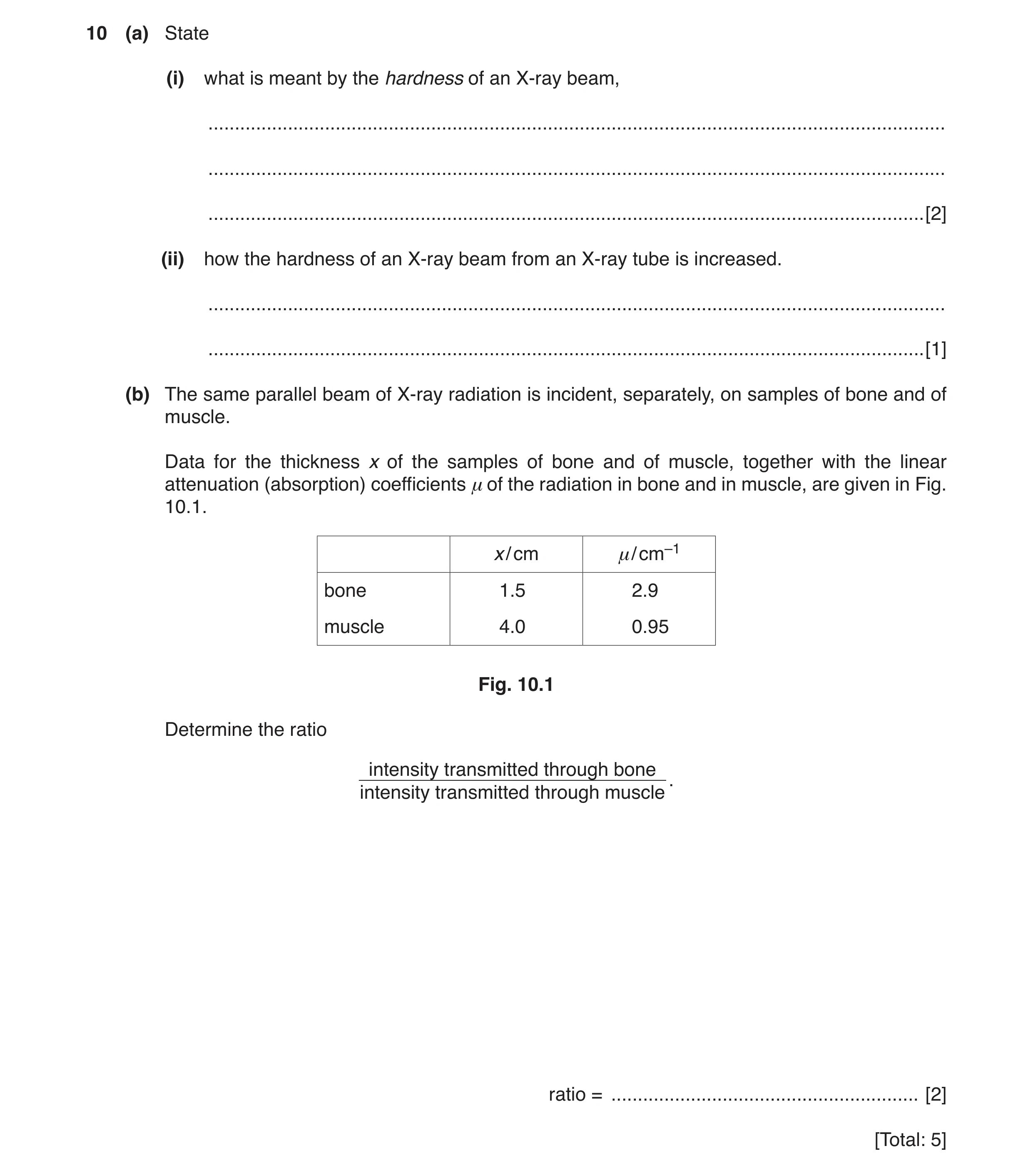
10 (a) State (i) what is meant by the hardness of an X-ray beam, … … … [2] (ii) how the hardness of an X-ray beam from an X-ray tube is increased. … … [1] (b) The same parallel beam of X-ray radiation is incident, separately, on samples of bone and of muscle. Data for the thickness x of the samples of bone and of muscle, together with the linear attenuation (absorption) coefficients μ of the radiation in bone and in muscle, are given in Fig. 10.1. x / cm μ/ cm–1 bone 1.5 2.9 muscle 4.0 0.95 Fig. 10.1 Determine the ratio intensity transmitted through bone . intensity transmitted through muscle ratio = … [2] [Total: 5]
5 marks
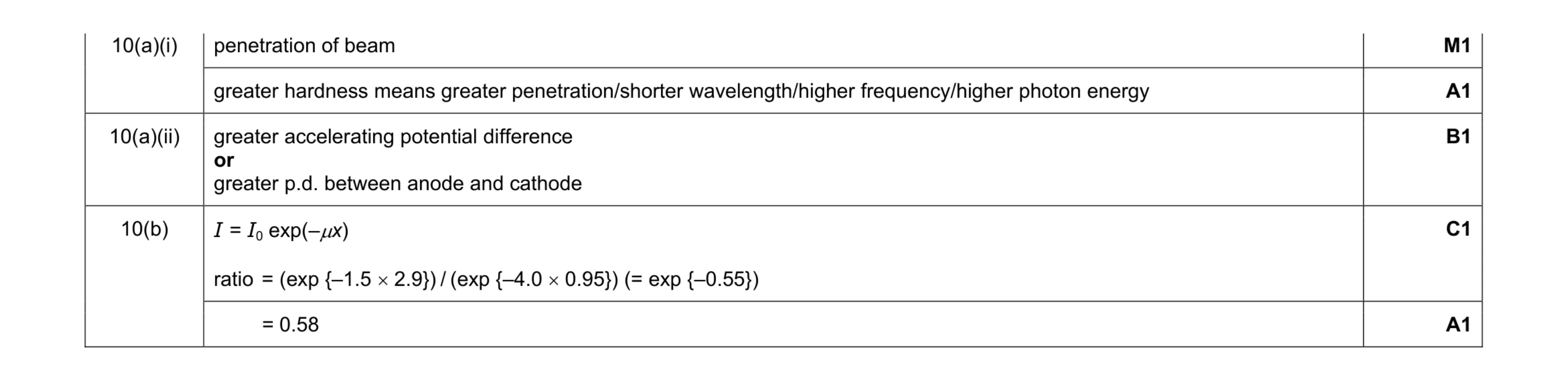
Mark scheme: 10(a)(i) penetration of beam M1 greater hardness means greater penetration/shorter wavelength/higher frequency/higher photon energy A1 10(a)(ii) greater accelerating potential difference or greater p.d. between anode and cathode B1 10(b) I = I0 exp(–µx) ratio = (exp {–1.5 × 2.9}) / (exp {–4.0 × 0.95}) (= exp {–0.55}) C1 = 0.58 A1
This question in 9702/41 May/June 2017
Q2 · State (i) what is meant by the hardness of an X-ray beam, … … … [2] (ii) how the hardness… 9702/43 May/June 2017
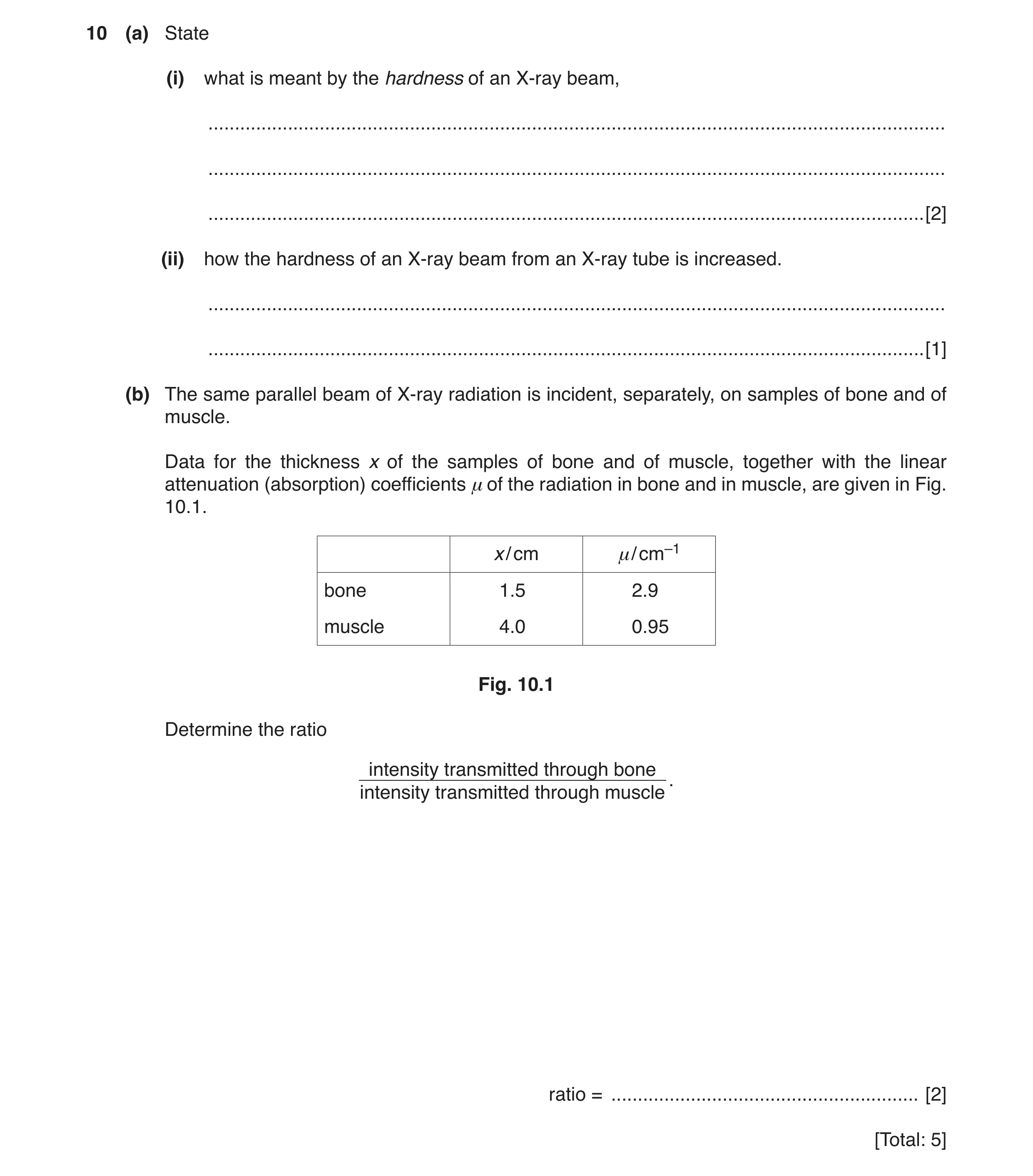
10 (a) State (i) what is meant by the hardness of an X-ray beam, … … … [2] (ii) how the hardness of an X-ray beam from an X-ray tube is increased. … … [1] (b) The same parallel beam of X-ray radiation is incident, separately, on samples of bone and of muscle. Data for the thickness x of the samples of bone and of muscle, together with the linear attenuation (absorption) coefficients μ of the radiation in bone and in muscle, are given in Fig. 10.1. x / cm μ/ cm–1 bone 1.5 2.9 muscle 4.0 0.95 Fig. 10.1 Determine the ratio intensity transmitted through bone . intensity transmitted through muscle ratio = … [2] [Total: 5]
5 marks
Mark scheme: 10(a)(i) penetration of beam M1 greater hardness means greater penetration/shorter wavelength/higher frequency/higher photon energy A1 10(a)(ii) greater accelerating potential difference or greater p.d. between anode and cathode B1 10(b) I = I0 exp(–µx) ratio = (exp {–1.5 × 2.9}) / (exp {–4.0 × 0.95}) (= exp {–0.55}) C1 = 0.58 A1
This question in 9702/43 May/June 2017
Q3 · In computed tomography (CT scanning), it is necessary to take a series of many X-ray… 9702/41 Oct/Nov 2017
9 (a) In computed tomography (CT scanning), it is necessary to take a series of many X-ray images. Outline briefly the principles of CT scanning. … … … … … … … … … … [4] (b) A student creates a model for CT scanning. A section is divided into four voxels, with pixel numbers A, B, C and D, as shown in Fig. 9.1. A B V1 D C V2 V4 V3 Fig. 9.1 The section is viewed from four different directions V1, V2, V3 and V4, as shown in Fig. 9.1. The detector readings for each direction are noted and then summed. The result is shown in Fig. 9.2. 47 59 44 32 Fig. 9.2 The background count is 26. Determine the pixel numbers A, B, C and D as shown in Fig. 9.1. A … B … D … C … [3] [Total: 7]
7 marks
Mark scheme: 9(a) image of one slice/section (B1) images (of one slice) taken from different angles (M1) to give 2D image (of one slice) (A1) (repeated for) many slices (M1) to build up 3D image (of whole body/structure) (A1) Max. 4 marks total 4 9(b) evidence of subtraction of background (–26) C1 evidence of division by three C1 7 11 6 2 A1
This question in 9702/41 Oct/Nov 2017
Q4 · In computed tomography (CT scanning), it is necessary to take a series of many X-ray… 9702/43 Oct/Nov 2017
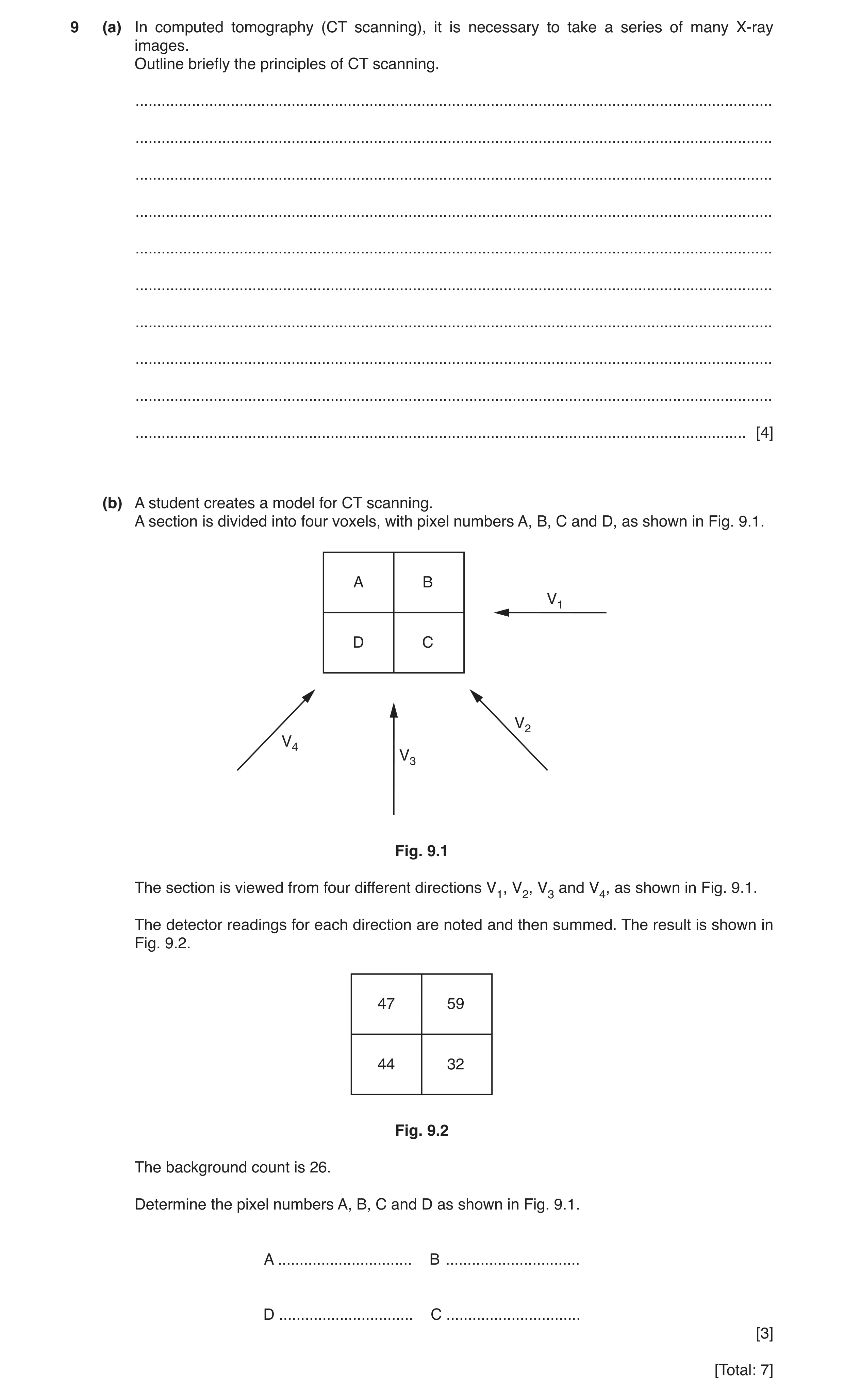
9 (a) In computed tomography (CT scanning), it is necessary to take a series of many X-ray images. Outline briefly the principles of CT scanning. … … … … … … … … … … [4] (b) A student creates a model for CT scanning. A section is divided into four voxels, with pixel numbers A, B, C and D, as shown in Fig. 9.1. A B V1 D C V2 V4 V3 Fig. 9.1 The section is viewed from four different directions V1, V2, V3 and V4, as shown in Fig. 9.1. The detector readings for each direction are noted and then summed. The result is shown in Fig. 9.2. 47 59 44 32 Fig. 9.2 The background count is 26. Determine the pixel numbers A, B, C and D as shown in Fig. 9.1. A … B … D … C … [3] [Total: 7]
7 marks
Mark scheme: 9(a) image of one slice/section (B1) images (of one slice) taken from different angles (M1) to give 2D image (of one slice) (A1) (repeated for) many slices (M1) to build up 3D image (of whole body/structure) (A1) Max. 4 marks total 4 9(b) evidence of subtraction of background (–26) C1 evidence of division by three C1 7 11 6 2 A1
This question in 9702/43 Oct/Nov 2017
Q5 · Suggest two causes of lack of sharpness of an X-ray image 9702/42 Feb/March 2018
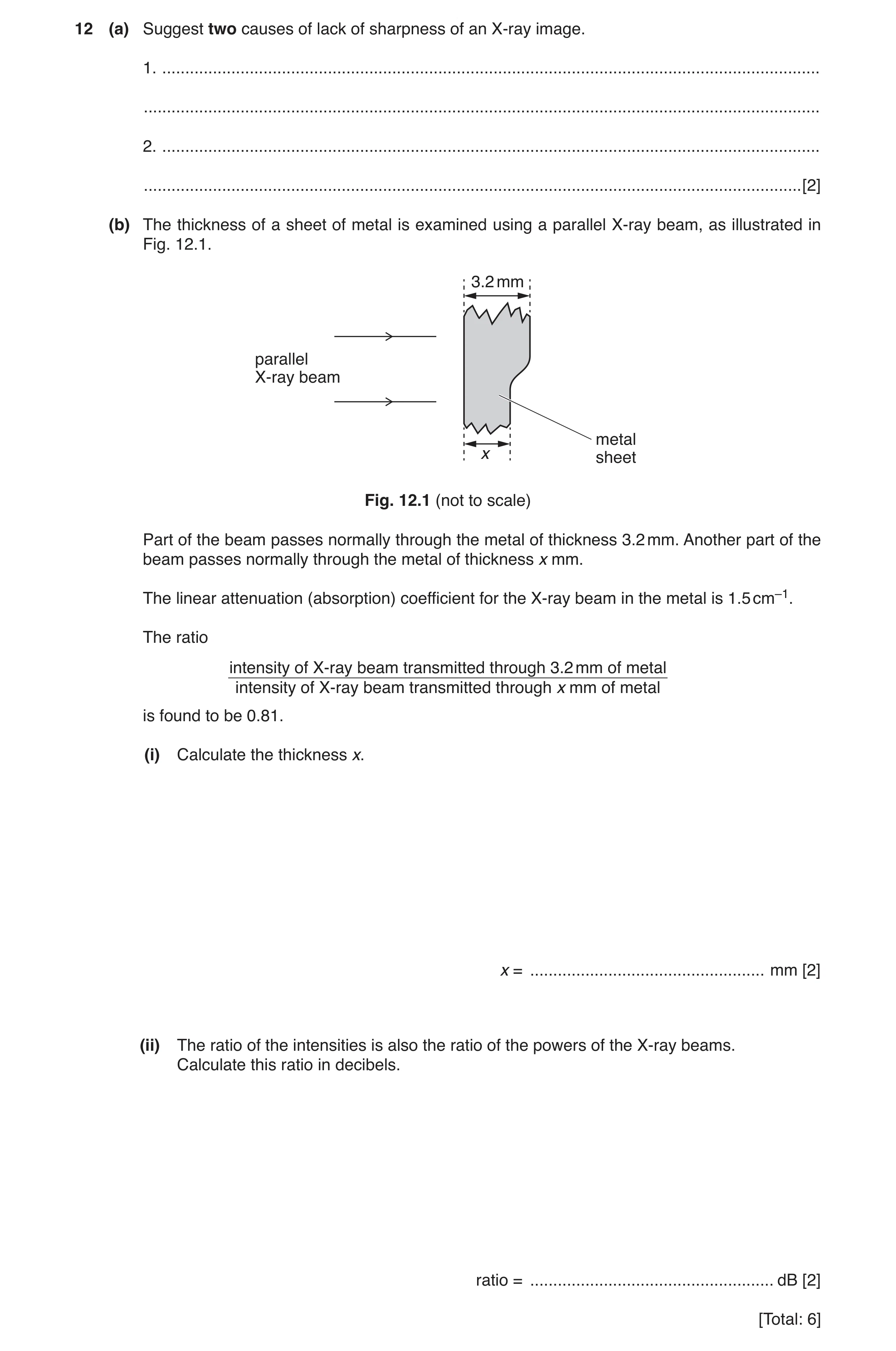
12 (a) Suggest two causes of lack of sharpness of an X-ray image. 1. … … 2. … … [2] (b) The thickness of a sheet of metal is examined using a parallel X-ray beam, as illustrated in Fig. 12.1. 3.2 mm parallel X-ray beam metal x sheet Fig. 12.1 (not to scale) Part of the beam passes normally through the metal of thickness 3.2 mm. Another part of the beam passes normally through the metal of thickness x mm. The linear attenuation (absorption) coefficient for the X-ray beam in the metal is 1.5 cm–1. The ratio intensity of X-ray beam transmitted through 3.2 mm of metal intensity of X-ray beam transmitted through x mm of metal is found to be 0.81. (i) Calculate the thickness x. x = … mm [2] (ii) The ratio of the intensities is also the ratio of the powers of the X-ray beams. Calculate this ratio in decibels. ratio = … dB [2] [Total: 6]
6 marks
Mark scheme: 12(a) Any 2 from: scattering of X-ray beam / no lead grid lack of collimation of beam / aperture large anode area large beam p.d. low / photon energy low / X-ray soft B2 12(b)(i) 0.81 = (e–1.5 × 0.32) / (e–1.5 × x) C1 x = 1.8 mm A1 Question Answer Marks 12(b)(ii) ratio/dB = 10 lg(0.81) C1 = (–) 0.92 dB A1
This question in 9702/42 Feb/March 2018
Q6 · An X-ray beam is used to produce an image of a model of a thumb 9702/41 May/June 2018
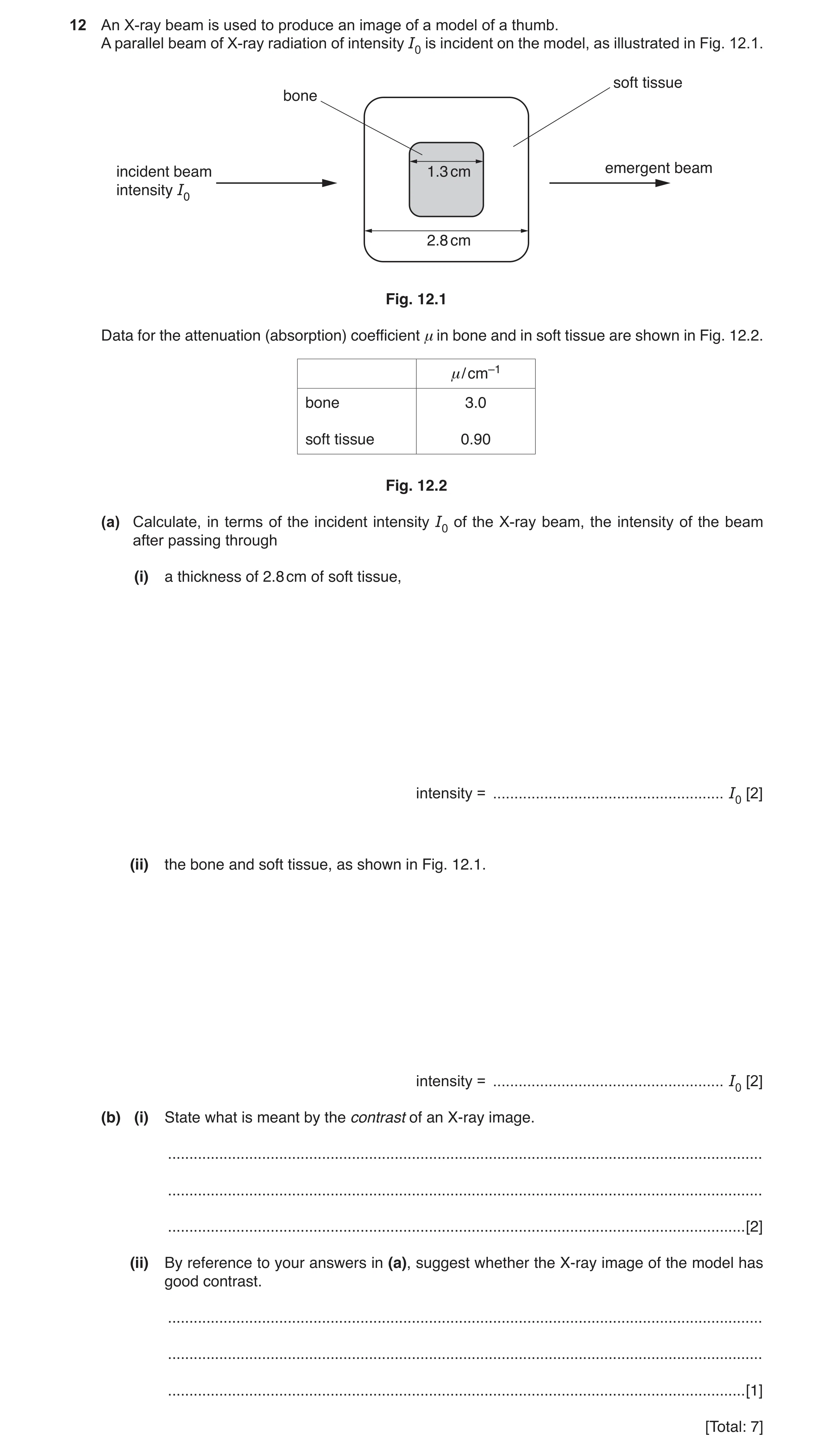
12 An X-ray beam is used to produce an image of a model of a thumb. A parallel beam of X-ray radiation of intensity I0 is incident on the model, as illustrated in Fig. 12.1. soft tissue bone incident beam 1.3 cm emergent beam intensity I0 2.8 cm Fig. 12.1 Data for the attenuation (absorption) coefficient μ in bone and in soft tissue are shown in Fig. 12.2. μ/ cm–1 bone 3.0 soft tissue 0.90 Fig. 12.2 (a) Calculate, in terms of the incident intensity I0 of the X-ray beam, the intensity of the beam after passing through (i) a thickness of 2.8 cm of soft tissue, intensity = … I0 [2] (ii) the bone and soft tissue, as shown in Fig. 12.1. intensity = … I0 [2] (b) (i) State what is meant by the contrast of an X-ray image. … … … [2] (ii) By reference to your answers in (a), suggest whether the X-ray image of the model has good contrast. … … … [1] [Total: 7]
7 marks
Mark scheme: 12(a)(i) C1 = I0 exp (–0.90 × 2.8) = 0.080 I0 A1 12(a)(ii) I = I0 exp [(–0.90 × 1.5) × (–3.0 × 1.3)] C1 = I0 (0.259 × 0.20) = 0.0052 I0 A1 12(b)(i) difference in degrees of blackening M1 between structures A1 12(b)(ii) large difference in intensities so good contrast B1
This question in 9702/41 May/June 2018
Q7 · Describe the basic principles of CT scanning (computed tomography) 9702/42 May/June 2018
11 (a) Describe the basic principles of CT scanning (computed tomography). … … … … … … … … … … … … [5] (b) By reference to your answer in (a), suggest why (i) CT scanning was not possible before fast computers with large memories were available, … … … [1] (ii) the radiation dose for a CT scan is much larger than for an X-ray image of a leg bone. … … … [1] [Total: 7]
7 marks
Mark scheme: 11(a) X-ray image(s) taken of one slice M1 (many images) taken from different angles A1 (computer) produces 2D image of slice B1 (this is) repeated for (many) slices M1 to build up a 3D image (of structure) A1 11(b)(i) combining of images involves (very) large number of calculations B1 11(b)(ii) CT scan consists of (very) many (single X-ray) images B1
This question in 9702/42 May/June 2018
Q8 · An X-ray beam is used to produce an image of a model of a thumb 9702/43 May/June 2018
12 An X-ray beam is used to produce an image of a model of a thumb. A parallel beam of X-ray radiation of intensity I0 is incident on the model, as illustrated in Fig. 12.1. soft tissue bone incident beam 1.3 cm emergent beam intensity I0 2.8 cm Fig. 12.1 Data for the attenuation (absorption) coefficient μ in bone and in soft tissue are shown in Fig. 12.2. μ/ cm–1 bone 3.0 soft tissue 0.90 Fig. 12.2 (a) Calculate, in terms of the incident intensity I0 of the X-ray beam, the intensity of the beam after passing through (i) a thickness of 2.8 cm of soft tissue, intensity = … I0 [2] (ii) the bone and soft tissue, as shown in Fig. 12.1. intensity = … I0 [2] (b) (i) State what is meant by the contrast of an X-ray image. … … … [2] (ii) By reference to your answers in (a), suggest whether the X-ray image of the model has good contrast. … … … [1] [Total: 7]
7 marks
Mark scheme: 12(a)(i) C1 = I0 exp (–0.90 × 2.8) = 0.080 I0 A1 12(a)(ii) I = I0 exp [(–0.90 × 1.5) × (–3.0 × 1.3)] C1 = I0 (0.259 × 0.20) = 0.0052 I0 A1 12(b)(i) difference in degrees of blackening M1 between structures A1 12(b)(ii) large difference in intensities so good contrast B1
This question in 9702/43 May/June 2018
Q9 · The root-mean-square (r.m.s.) value of the voltage of a sinusoidal alternating supply is… 9702/42 Oct/Nov 2018
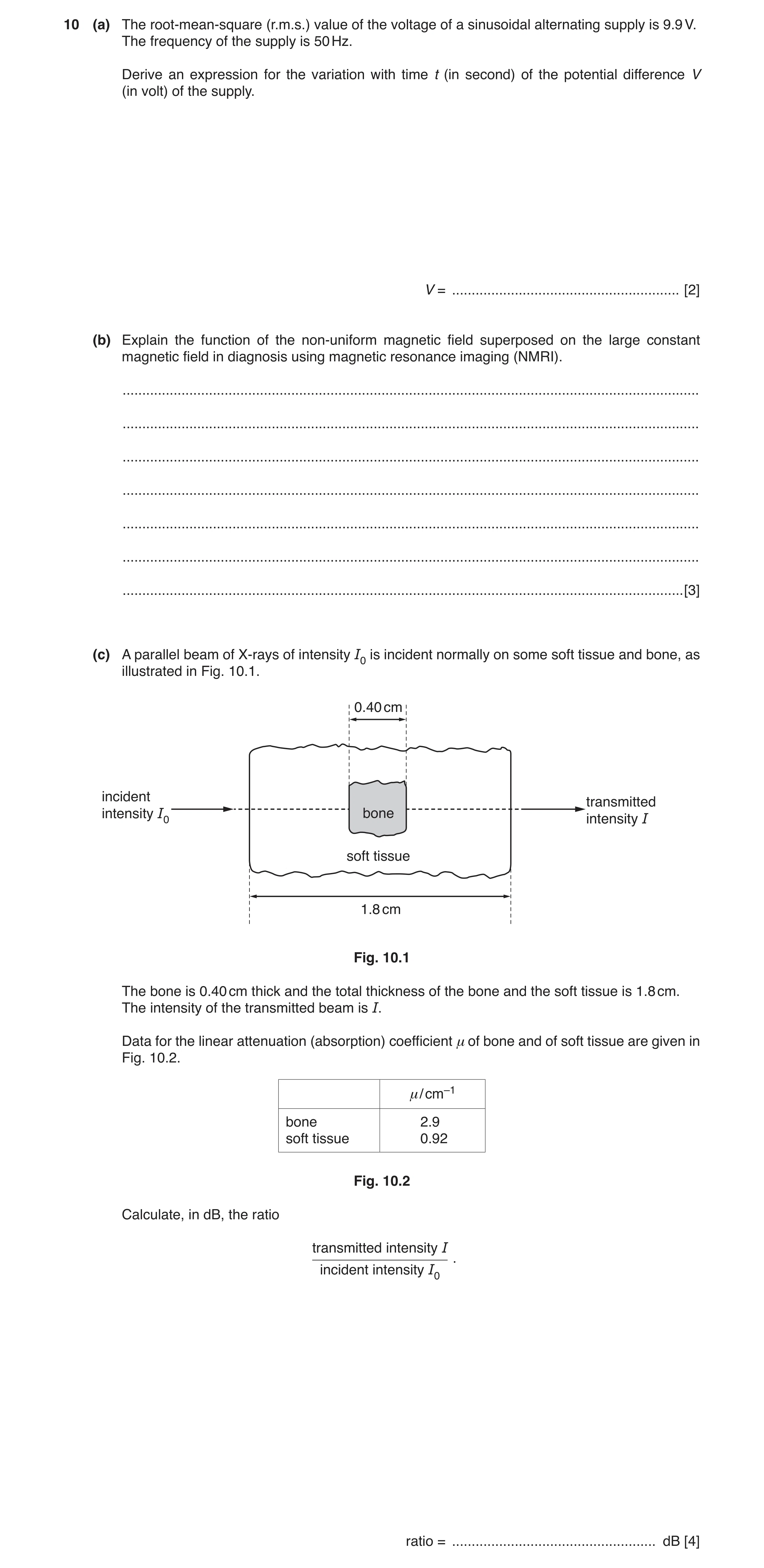
10 (a) The root-mean-square (r.m.s.) value of the voltage of a sinusoidal alternating supply is 9.9 V. The frequency of the supply is 50 Hz. Derive an expression for the variation with time t (in second) of the potential difference V (in volt) of the supply. V = … [2] (b) Explain the function of the non-uniform magnetic field superposed on the large constant magnetic field in diagnosis using magnetic resonance imaging (NMRI). … … … … … … … [3] (c) A parallel beam of X-rays of intensity I0 is incident normally on some soft tissue and bone, as illustrated in Fig. 10.1. 0.40 cm incident transmitted intensity I0 bone intensity I soft tissue 1.8 cm Fig. 10.1 The bone is 0.40 cm thick and the total thickness of the bone and the soft tissue is 1.8 cm. The intensity of the transmitted beam is I. Data for the linear attenuation (absorption) coefficient μ of bone and of soft tissue are given in Fig. 10.2. μ/ cm–1 bone 2.9 soft tissue 0.92 Fig. 10.2 Calculate, in dB, the ratio transmitted intensity I . incident intensity I0 ratio = … dB [4]
9 marks
Mark scheme: 10(a) and ω = 2πf = 2π × 50 (= 314 rad s–1) C1 V = 14 sin 314t A1 10(b) enables (resonating) nuclei to be located B1 resonant frequency depends on magnetic field strength B1 Any one from: • non-uniform field is (accurately) calibrated • (non-uniform) field may be varied to enable detection in different positions • unique (magnetic) field strength/frequency at each point B1 10(c) I = I0 exp(–µx) C1 I = I0 [exp(–µx)bone × exp(–µx)soft tissue] I = I0 [exp(–2.9 × 0.40) × exp(–0.92 × 1.4)] C1 I / I0 = 0.0865 C1 ratio / dB = 10 lg 0.0865 = –11 dB A1
This question in 9702/42 Oct/Nov 2018
Q10 · Outline the principles of computed tomography (CT) scanning 9702/42 Feb/March 2019
9 Outline the principles of computed tomography (CT) scanning. … … … … … … … … … … … [5] [Total: 5]
5 marks
Mark scheme: 9 X-rays (are used) B1 (object is) scanned in sections / slices B1 either: scans taken at many angles / directions or images of each section / slice are 2-dimensional B1 scans of many sections / slices are combined B1 (to give) 3-dimensional image (of whole structure) B1
This question in 9702/42 Feb/March 2019
Q11 · Describe the principles of computed tomography (CT) scanning 9702/42 Oct/Nov 2019
7 Describe the principles of computed tomography (CT) scanning. … … … … … … … … [5]
5 marks
Mark scheme: 7 X-rays are used B1 section (of object) is scanned B1 scans/images taken at many angles/directions or images of each section are 2-dimensional B1 images of (many) sections are combined B1 (to give) 3-dimensional image of (whole) structure B1
This question in 9702/42 Oct/Nov 2019
Q12 · Electrons are accelerated through a potential difference of 100 kV 9702/42 Feb/March 2020
11 Electrons are accelerated through a potential difference of 100 kV. They are then incident on a metal target, they decelerate, and X-ray photons are emitted. (a) Calculate the maximum possible frequency of the emitted X-ray photons. frequency = … Hz [2] (b) Explain why an aluminium filter may be placed in the X-ray beam when producing an X-ray image of a patient. … … … … … … [3] (c) The linear attenuation (absorption) coefficients μ for X-rays in bone, blood and muscle are given in Table 11.1. Table 11.1 μ/ cm−1 bone 3.0 blood 0.23 muscle 0.22 (i) A beam of these X-rays is incident on a person. Calculate the percentage of the intensity of the X-ray beam that has been absorbed after passing through 0.80 cm of blood. percentage of intensity absorbed = … % [2] (ii) In an X-ray image, white regions show greater absorption of X-rays than dark regions. State and explain the difference between the X-ray image of bone compared to that of muscle. … … … [2] [Total: 9]
9 marks
Mark scheme: 11(a) eV = hf f = 1.60 × 10–19 × 100 000 / 6.63 × 10–34 = 2.41 × 10¹⁹ Hz A1 11(b) (aluminium filter) absorbs (most) low energy X-rays B1 Any 2 from • X-ray beam contains many wavelengths • so low energy X-rays are not absorbed in the body • low energy X-rays can can cause harm but do not contribute to the image B2 11(c)(i) I / Io = e– μx e–0.23 × 0.80 = 0.83 C1 17% absorbed A1 11(c)(ii) bone is seen as lighter / muscle is seen as darker B1 either bone has a higher µ value so absorbs more or muscle has a lower µ value so transmits more B1
This question in 9702/42 Feb/March 2020
Q13 · Outline briefly the principles of computed tomography (CT scanning) 9702/41 Oct/Nov 2020
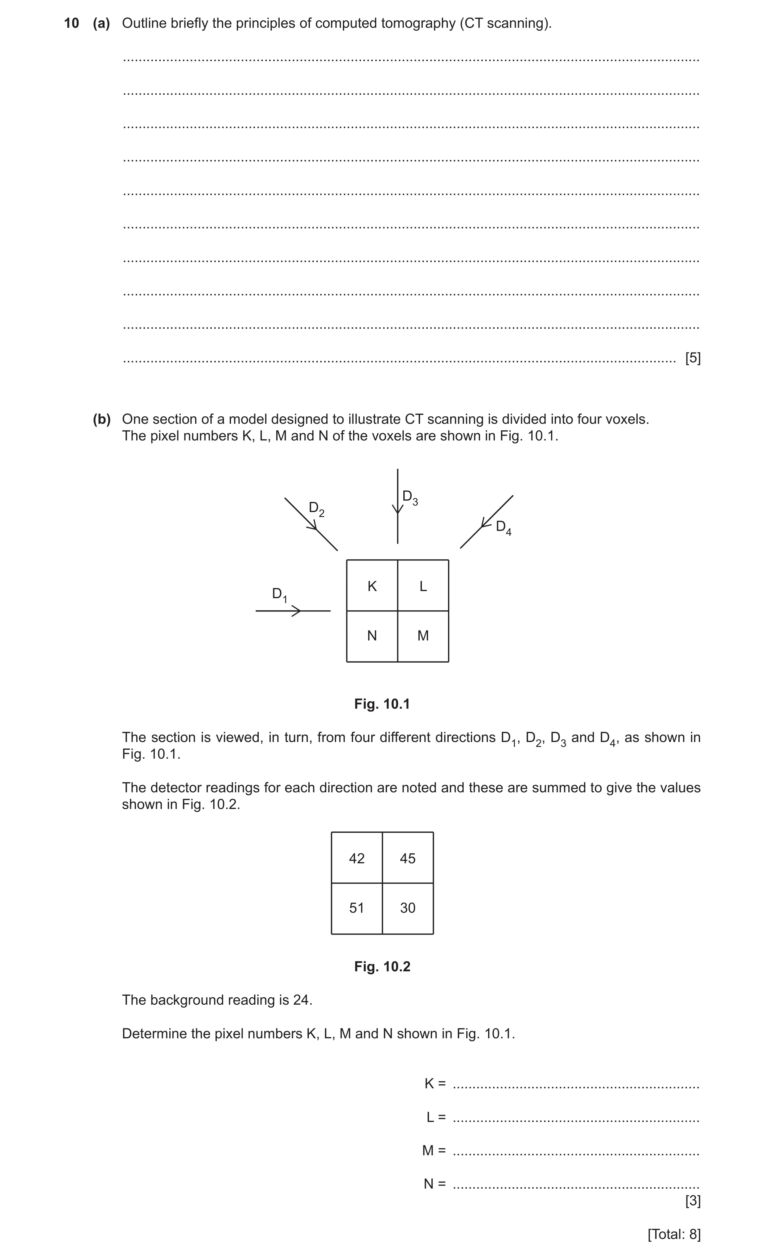
10 (a) Outline briefly the principles of computed tomography (CT scanning). … … … … … … … … … … [5] (b) One section of a model designed to illustrate CT scanning is divided into four voxels. The pixel numbers K, L, M and N of the voxels are shown in Fig. 10.1. D3 D2 D4 K L D1 N M Fig. 10.1 The section is viewed, in turn, from four different directions D1, D2, D3 and D4, as shown in Fig. 10.1. The detector readings for each direction are noted and these are summed to give the values shown in Fig. 10.2. 42 45 51 30 Fig. 10.2 The background reading is 24. Determine the pixel numbers K, L, M and N shown in Fig. 10.1. K = … L = … M = … N = … [3] [Total: 8]
8 marks
Mark scheme: 10(a) X-rays are used B1 section (of object) is scanned B1 scans/images taken at many angles/directions or images of each section are 2-dimensional B1 (images of (many)) sections are combined B1 (to give) 3-dimensional image of (whole) structure B1 10(b) K = 6 L = 7 M = 2 N = 9 3 marks: all four correct 2 marks: three correct and one incorrect or all correct with two numbers transposed 1 mark: two correct and two incorrect B3
This question in 9702/41 Oct/Nov 2020
Q14 · Electrons in a beam are travelling at high speed in a vacuum 9702/42 Oct/Nov 2020
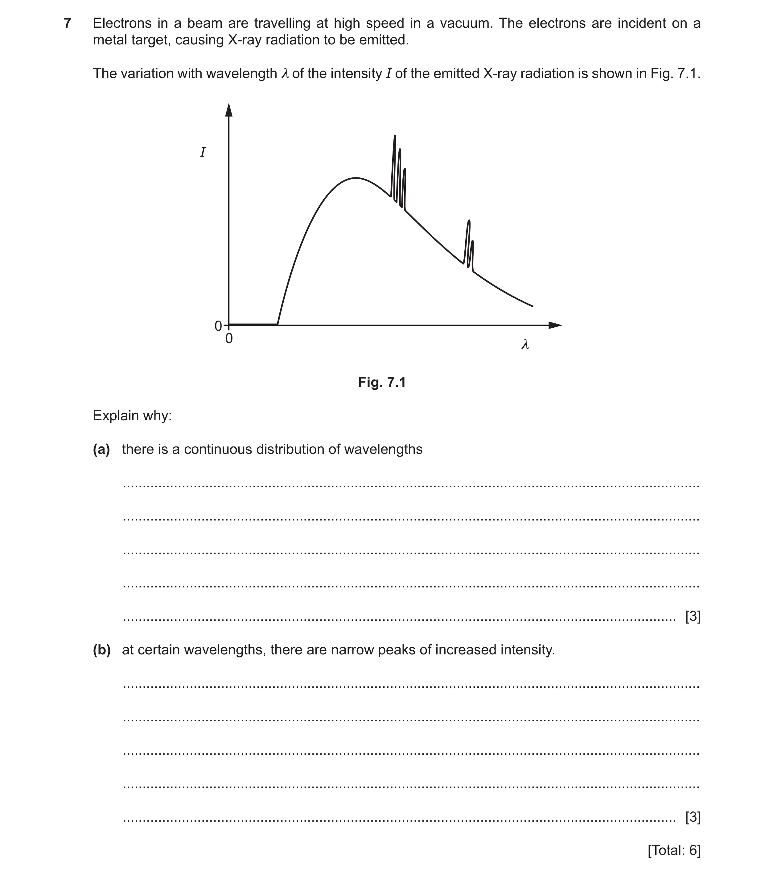
7 Electrons in a beam are travelling at high speed in a vacuum. The electrons are incident on a metal target, causing X-ray radiation to be emitted. The variation with wavelength λ of the intensity I of the emitted X-ray radiation is shown in Fig. 7.1. I 0 0 λ Fig. 7.1 Explain why: (a) there is a continuous distribution of wavelengths … … … … … [3] (b) at certain wavelengths, there are narrow peaks of increased intensity. … … … … … [3] [Total: 6]
6 marks
Mark scheme: 7(a) X-ray photon produced when electron is decelerated B1 larger acceleration results in larger photon energy B1 continuous range of accelerations so continuous spectrum of wavelengths/frequencies B1 7(b) electron in (inner shell of) target atom is excited (on collision) B1 electron de-excites causing emission of a photon B1 discrete energy levels so discrete photon wavelengths B1
This question in 9702/42 Oct/Nov 2020
Q15 · Outline briefly the principles of computed tomography (CT scanning) 9702/43 Oct/Nov 2020
10 (a) Outline briefly the principles of computed tomography (CT scanning). … … … … … … … … … … [5] (b) One section of a model designed to illustrate CT scanning is divided into four voxels. The pixel numbers K, L, M and N of the voxels are shown in Fig. 10.1. D3 D2 D4 K L D1 N M Fig. 10.1 The section is viewed, in turn, from four different directions D1, D2, D3 and D4, as shown in Fig. 10.1. The detector readings for each direction are noted and these are summed to give the values shown in Fig. 10.2. 42 45 51 30 Fig. 10.2 The background reading is 24. Determine the pixel numbers K, L, M and N shown in Fig. 10.1. K = … L = … M = … N = … [3] [Total: 8]
8 marks
Mark scheme: 10(a) X-rays are used B1 section (of object) is scanned B1 scans/images taken at many angles/directions or images of each section are 2-dimensional B1 (images of (many)) sections are combined B1 (to give) 3-dimensional image of (whole) structure B1 10(b) K = 6 L = 7 M = 2 N = 9 3 marks: all four correct 2 marks: three correct and one incorrect or all correct with two numbers transposed 1 mark: two correct and two incorrect B3
This question in 9702/43 Oct/Nov 2020
Q16 · Electrons are accelerated through a potential difference of 15 kV 9702/42 Feb/March 2021
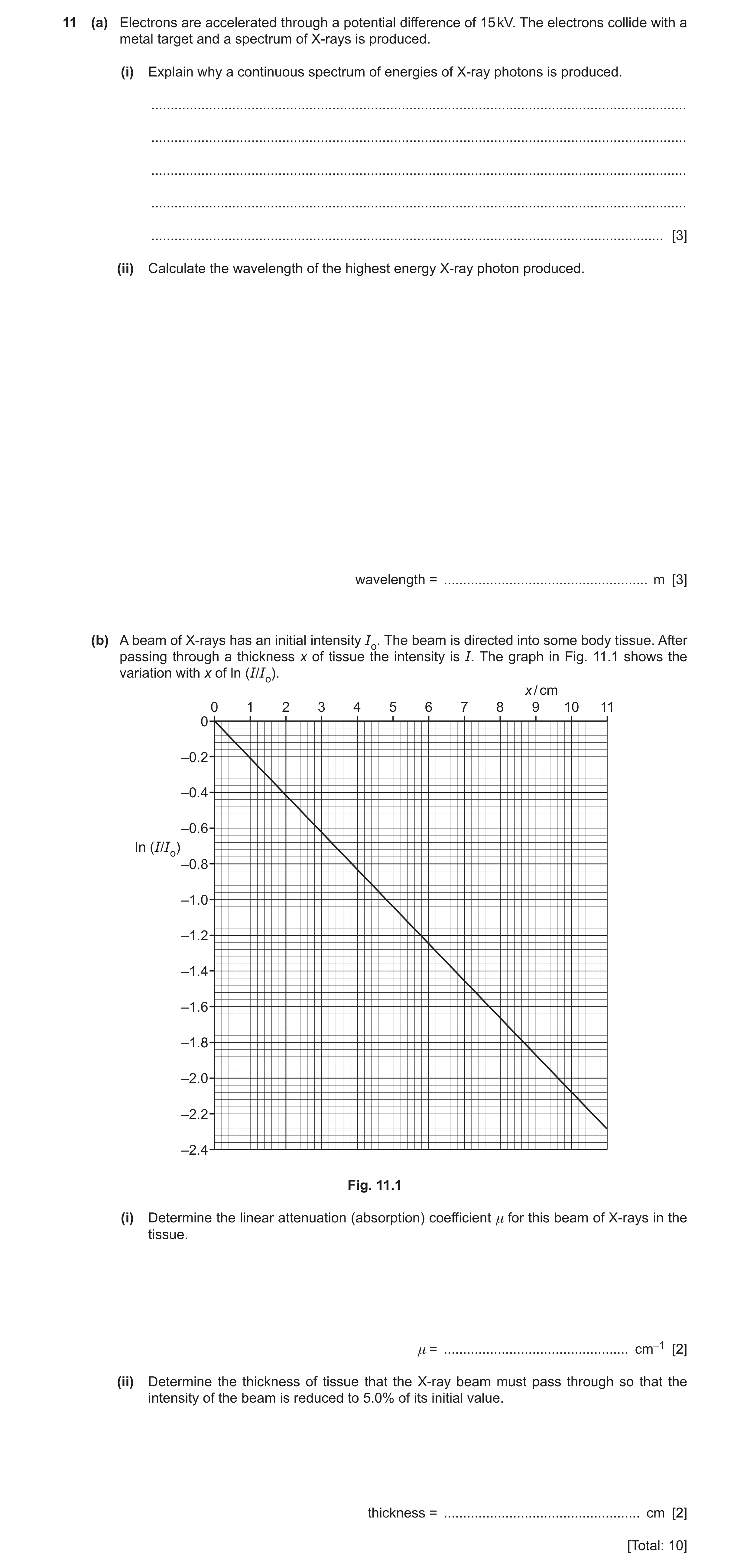
11 (a) Electrons are accelerated through a potential difference of 15 kV. The electrons collide with a metal target and a spectrum of X-rays is produced. (i) Explain why a continuous spectrum of energies of X-ray photons is produced. … … … … … [3] (ii) Calculate the wavelength of the highest energy X-ray photon produced. wavelength = … m [3] (b) A beam of X-rays has an initial intensity Io. The beam is directed into some body tissue. After passing through a thickness x of tissue the intensity is I. The graph in Fig. 11.1 shows the variation with x of ln (I/Io). x / cm 0 1 2 3 4 5 6 7 8 9 10 11 0 –0.2 –0.4 –0.6 In (I/Io) –0.8 –1.0 –1.2 –1.4 –1.6 –1.8 –2.0 –2.2 –2.4 Fig. 11.1 (i) Determine the linear attenuation (absorption) coefficient μ for this beam of X-rays in the tissue. μ = … cm–1 [2] (ii) Determine the thickness of tissue that the X-ray beam must pass through so that the intensity of the beam is reduced to 5.0% of its initial value. thickness = … cm [2] [Total: 10]
10 marks
Mark scheme: 11(a)(i) electrons decelerate (on hitting target) so X-ray photons produced B1 range of decelerations B1 photon energy depends on (magnitude of) deceleration B1 11(a)(ii) hc eV λ = C1 34 8 19 6.63 10 3.0 10 1.6 10 15000 λ − − × × × = × × C1 11 8.3 10 m − = × A1 or E = hf and c = fλ and electron energy = eV or E = hc / λ and electron energy = eV electron energy = 1.6 × 10–19 × 15000 = 2.4 × 10⁻¹⁵ (C1) 34 8 15 6.63 10 3.0 10 2.4 10 λ − − × × × = × (C1) 11 8.3 10 m λ − = × (A1) 11(b)(i) μ = – gradient or ln (I / Io) = x μ − C1 (e.g. 2.08 / 10.0) = 0.21 cm–1 A1 Question Answer Marks 11(b)(ii) ( ) ln 0.05 x μ = − C1 ln0.05 x μ = − . . 14 e g x cm = A1
This question in 9702/42 Feb/March 2021
Q17 · State how, in a modern X-ray tube, the intensity of the X-ray beam and its hardness are… 9702/41 May/June 2021
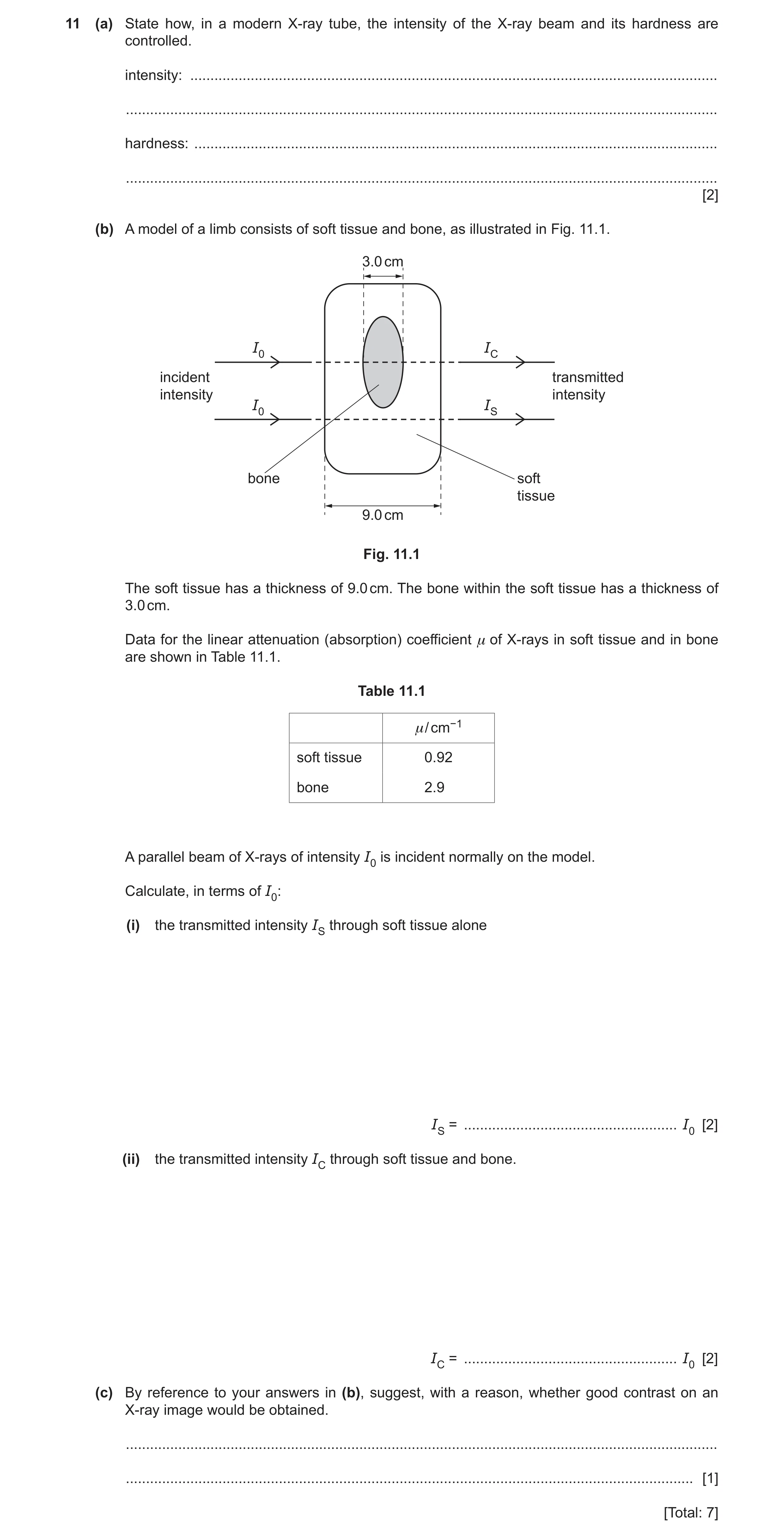
11 (a) State how, in a modern X-ray tube, the intensity of the X-ray beam and its hardness are controlled. intensity: … … hardness: … … [2] (b) A model of a limb consists of soft tissue and bone, as illustrated in Fig. 11.1. 3.0 cm I0 IC incident transmitted intensity intensity I0 IS bone soft tissue 9.0 cm Fig. 11.1 The soft tissue has a thickness of 9.0 cm. The bone within the soft tissue has a thickness of 3.0 cm. Data for the linear attenuation (absorption) coefficient μ of X-rays in soft tissue and in bone are shown in Table 11.1. Table 11.1 μ / cm−1 soft tissue 0.92 bone 2.90 A parallel beam of X-rays of intensity I0 is incident normally on the model. Calculate, in terms of I0: (i) the transmitted intensity IS through soft tissue alone IS = … I0 [2] (ii) the transmitted intensity IC through soft tissue and bone. IC = … I0 [2] (c) By reference to your answers in (b), suggest, with a reason, whether good contrast on an X-ray image would be obtained. … … [1] [Total: 7]
7 marks
Mark scheme: 11(a) intensity: vary filament current/p.d. across filament B1 hardness: vary accelerating potential difference B1 11(b)(i) I = I0e –μx C1 IS = I0 exp(–0.92 × 9.0) = 2.5 × 10⁻⁴ I0 A1 11(b)(ii) IC = [exp(–0.92 × 6.0) × exp(–2.9 × 3.0)] I0 C1 = 6.7 × 10⁻⁷ I0 A1 11(c) conclusion consistent with values in (b)(i) and (b)(ii) e.g. IS ≫ IC so good contrast B1
This question in 9702/41 May/June 2021
Q18 · State the purpose of computed tomography (CT scanning) 9702/42 May/June 2021
11 (a) State the purpose of computed tomography (CT scanning). … … [1] (b) Outline the principles of CT scanning. … … … … … … … … … … [5] [Total: 6]
6 marks
Mark scheme: 11(a) to produce a 3-dimensional image of structure/body B1 11(b) X-rays (are used) B1 scanning in sections B1 scanning from many angles B1 image of each section is 2-dimensional B1 scanning repeated for many sections or images of many sections combined together B1
This question in 9702/42 May/June 2021
Q19 · State how, in a modern X-ray tube, the intensity of the X-ray beam and its hardness are… 9702/43 May/June 2021
11 (a) State how, in a modern X-ray tube, the intensity of the X-ray beam and its hardness are controlled. intensity: … … hardness: … … [2] (b) A model of a limb consists of soft tissue and bone, as illustrated in Fig. 11.1. 3.0 cm I0 IC incident transmitted intensity intensity I0 IS bone soft tissue 9.0 cm Fig. 11.1 The soft tissue has a thickness of 9.0 cm. The bone within the soft tissue has a thickness of 3.0 cm. Data for the linear attenuation (absorption) coefficient μ of X-rays in soft tissue and in bone are shown in Table 11.1. Table 11.1 μ / cm−1 soft tissue 0.92 bone 2.90 A parallel beam of X-rays of intensity I0 is incident normally on the model. Calculate, in terms of I0: (i) the transmitted intensity IS through soft tissue alone IS = … I0 [2] (ii) the transmitted intensity IC through soft tissue and bone. IC = … I0 [2] (c) By reference to your answers in (b), suggest, with a reason, whether good contrast on an X-ray image would be obtained. … … [1] [Total: 7]
7 marks
Mark scheme: 11(a) intensity: vary filament current/p.d. across filament B1 hardness: vary accelerating potential difference B1 11(b)(i) I = I0e –μx C1 IS = I0 exp(–0.92 × 9.0) = 2.5 × 10⁻⁴ I0 A1 11(b)(ii) IC = [exp(–0.92 × 6.0) × exp(–2.9 × 3.0)] I0 C1 = 6.7 × 10⁻⁷ I0 A1 11(c) conclusion consistent with values in (b)(i) and (b)(ii) e.g. IS ≫ IC so good contrast B1
This question in 9702/43 May/June 2021
Q20 · State, for an X-ray image, what is meant by: (i) sharpness … … [1] (ii) contrast 9702/41 Oct/Nov 2021
11 (a) State, for an X-ray image, what is meant by: (i) sharpness … … [1] (ii) contrast. … … [1] (b) A parallel X-ray beam passes through a thickness of 2.3 cm of soft body tissue. The intensity of the emerging beam is 12% of the intensity of the incident beam. Calculate the linear attenuation (absorption) coefficient μ of the soft body tissue. Give a unit with your answer. μ = … unit … [3] (c) In medical diagnosis, X-rays may be used to produce a single X-ray image or may be used in computed tomography (CT scanning). Suggest an advantage and a disadvantage of CT scanning compared with single X-ray imaging for diagnosis. advantage: … … disadvantage: … … [2] [Total: 7]
7 marks
Mark scheme: 11(a)(i) ease with which edges can be distinguished B1 11(a)(ii) difference in degrees of blackening B1 11(b) I = I0 exp (–μx) C1 0.12 = exp (–μ × 2.3) ln 0.12 = –2.3 × μ C1 μ = 0.92 cm–1 A1 11(c) advantage: produces 3-dimensional image B1 disadvantage: (much) greater exposure to radiation B1
This question in 9702/41 Oct/Nov 2021
Q21 · State, for an X-ray image, what is meant by: (i) sharpness … … [1] (ii) contrast 9702/43 Oct/Nov 2021
11 (a) State, for an X-ray image, what is meant by: (i) sharpness … … [1] (ii) contrast. … … [1] (b) A parallel X-ray beam passes through a thickness of 2.3 cm of soft body tissue. The intensity of the emerging beam is 12% of the intensity of the incident beam. Calculate the linear attenuation (absorption) coefficient μ of the soft body tissue. Give a unit with your answer. μ = … unit … [3] (c) In medical diagnosis, X-rays may be used to produce a single X-ray image or may be used in computed tomography (CT scanning). Suggest an advantage and a disadvantage of CT scanning compared with single X-ray imaging for diagnosis. advantage: … … disadvantage: … … [2] [Total: 7]
7 marks
Mark scheme: 11(a)(i) ease with which edges can be distinguished B1 11(a)(ii) difference in degrees of blackening B1 11(b) I = I0 exp (–μx) C1 0.12 = exp (–μ × 2.3) ln 0.12 = –2.3 × μ C1 μ = 0.92 cm–1 A1 11(c) advantage: produces 3-dimensional image B1 disadvantage: (much) greater exposure to radiation B1
This question in 9702/43 Oct/Nov 2021
Q22 · In an X-ray tube, electrons are accelerated through a potential difference of 75 kV 9702/42 Feb/March 2022
10 In an X-ray tube, electrons are accelerated through a potential difference of 75 kV. The electrons then strike a tungsten target of effective mass 15 g. The electron energy is converted into the energy of X-ray photons with an efficiency of 5.0%. The rest of the energy is converted into thermal energy. (a) The X-ray tube produces an image using a current of 0.40 A for a time of 20 ms. The specific heat capacity of tungsten is 130 J kg–1 K–1. Determine the temperature rise ΔT of the tungsten target. ΔT = … K [3] (b) The linear attenuation coefficient of the X-ray photons in muscle is 0.22 cm–1. Calculate the thickness t of muscle that will absorb 80% of the incident X-ray intensity. t = … cm [2] (c) Table 10.1 shows the linear attenuation coefficient μ for the X-ray photons in different tissues. Table 10.1 μ/ cm–1 bone 3.0 blood 0.23 muscle 0.22 Two X-ray images are taken, one of equal thicknesses of bone and muscle and another of equal thicknesses of blood and muscle. Explain why one of these images has good contrast, but the other does not. … … … … [2] [Total: 7]
7 marks
Mark scheme: 10(a) C1 energy = ItV 0.40 0.020 75 000 0.95 ( T =) 0.015 130 × × × Δ × C1 =290 K A1 10(b) t oe μ − = I I 0.22t 0.20 = e− C1 t = 7.3 cm A1 Question Answer Marks 10(c) either (linear) attenuation coefficients / μ very different for bone and muscle M1 (very) different amounts (of X-rays) absorbed so good contrast or (very) different intensities transmitted so good contrast A1 or (linear) attenuation coefficients / μ similar for blood and muscle (M1) similar amounts (of X-rays) absorbed so poor contrast or similar intensities transmitted so poor contrast (A1)
This question in 9702/42 Feb/March 2022
Q23 · Explain how X-rays are produced for use in medical diagnosis 9702/41 May/June 2022
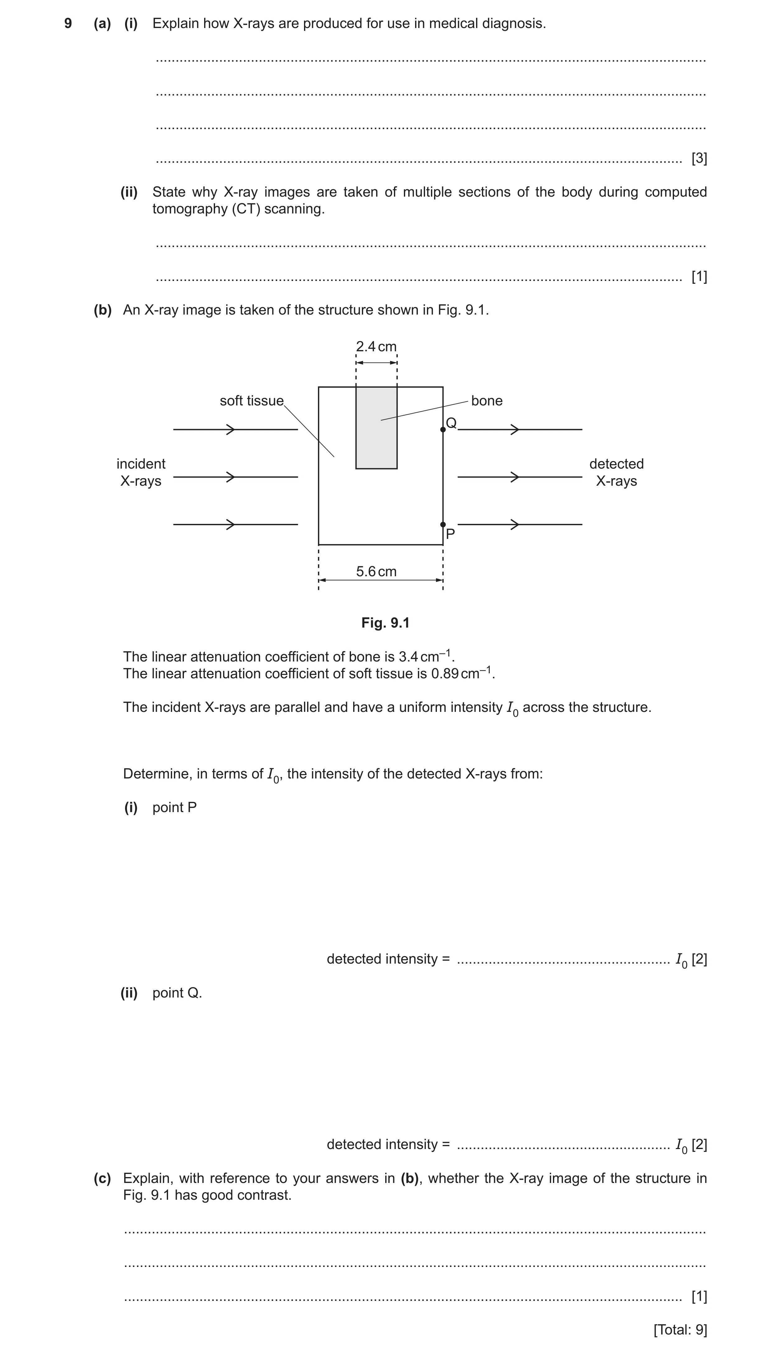
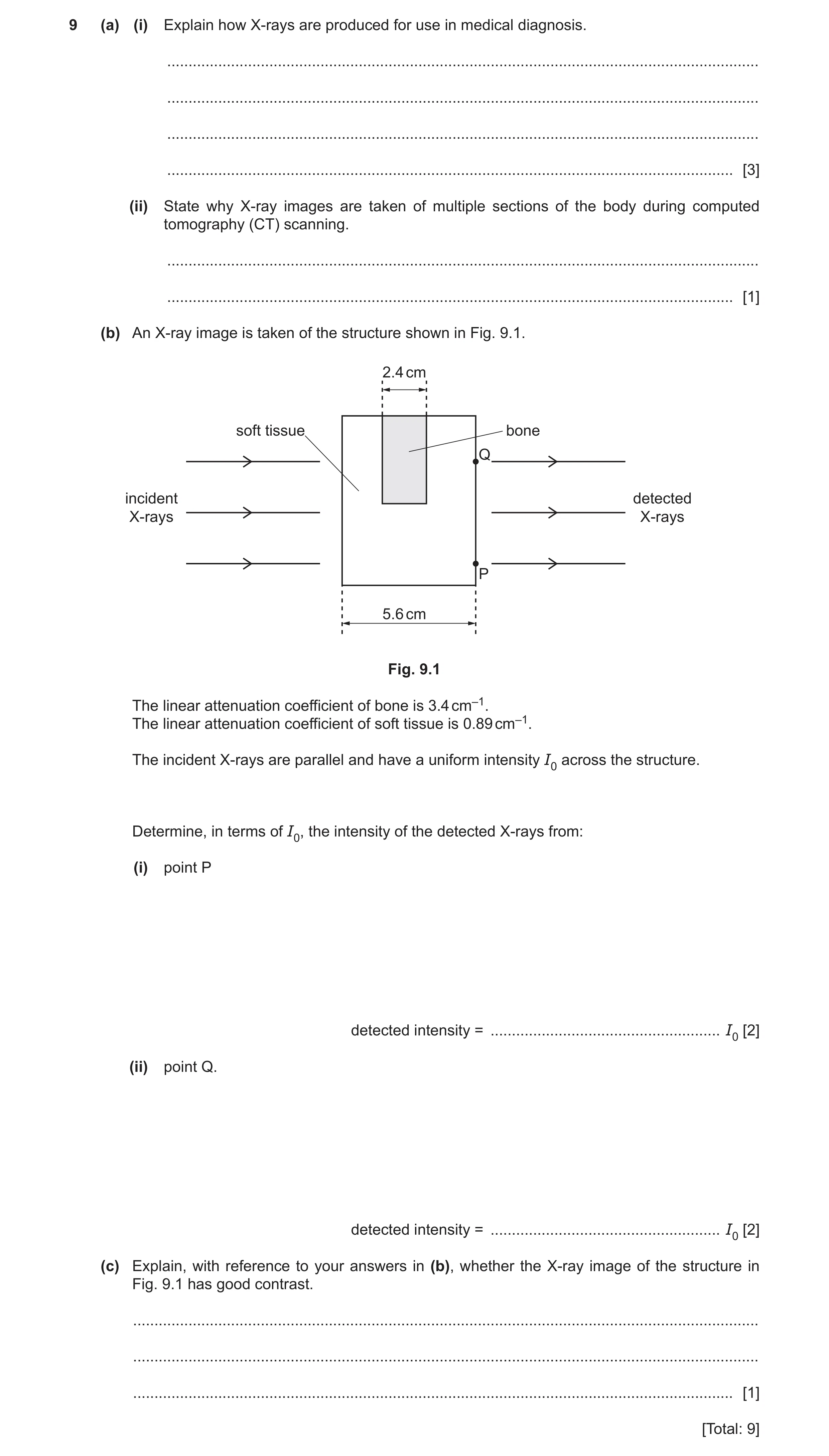
9 (a) (i) Explain how X-rays are produced for use in medical diagnosis. … … … … [3] (ii) State why X-ray images are taken of multiple sections of the body during computed tomography (CT) scanning. … … [1] (b) An X-ray image is taken of the structure shown in Fig. 9.1. 2.4 cm soft tissue bone Q incident detected X-rays X-rays P 5.6 cm Fig. 9.1 The linear attenuation coefficient of bone is 3.4 cm–1. The linear attenuation coefficient of soft tissue is 0.89 cm–1. The incident X-rays are parallel and have a uniform intensity I0 across the structure. Determine, in terms of I0, the intensity of the detected X-rays from: (i) point P detected intensity = … I0 [2] (ii) point Q. detected intensity = … I0 [2] (c) Explain, with reference to your answers in (b), whether the X-ray image of the structure in Fig. 9.1 has good contrast. … … … [1] [Total: 9]
9 marks
Mark scheme: 9(a)(i) electrons are accelerated (by an applied p.d.) B1 electrons hit target B1 X-rays produced when electrons decelerate B1 9(a)(ii) images of the multiple sections are combined to create a 3-D image B1 9(b)(i) I = I0 exp (– μx) C1 = I0 exp (– 0.89 5.6) = 0.0068 I0 A1 9(b)(ii) I = I0 exp (– 2.4 3.4) exp (– 0.89 3.2) C1 = 1.7 10–5 I0 A1 9(c) comparison of intensities or values in (b) leading to conclusion consistent with these values B1
This question in 9702/41 May/June 2022
Q24 · Explain how X-rays are produced for use in medical diagnosis 9702/43 May/June 2022
9 (a) (i) Explain how X-rays are produced for use in medical diagnosis. … … … … [3] (ii) State why X-ray images are taken of multiple sections of the body during computed tomography (CT) scanning. … … [1] (b) An X-ray image is taken of the structure shown in Fig. 9.1. 2.4 cm soft tissue bone Q incident detected X-rays X-rays P 5.6 cm Fig. 9.1 The linear attenuation coefficient of bone is 3.4 cm–1. The linear attenuation coefficient of soft tissue is 0.89 cm–1. The incident X-rays are parallel and have a uniform intensity I0 across the structure. Determine, in terms of I0, the intensity of the detected X-rays from: (i) point P detected intensity = … I0 [2] (ii) point Q. detected intensity = … I0 [2] (c) Explain, with reference to your answers in (b), whether the X-ray image of the structure in Fig. 9.1 has good contrast. … … … [1] [Total: 9]
9 marks
Mark scheme: 9(a)(i) electrons are accelerated (by an applied p.d.) B1 electrons hit target B1 X-rays produced when electrons decelerate B1 9(a)(ii) images of the multiple sections are combined to create a 3-D image B1 9(b)(i) I = I0 exp (– μx) C1 = I0 exp (– 0.89 5.6) = 0.0068 I0 A1 9(b)(ii) I = I0 exp (– 2.4 3.4) exp (– 0.89 3.2) C1 = 1.7 10–5 I0 A1 9(c) comparison of intensities or values in (b) leading to conclusion consistent with these values B1
This question in 9702/43 May/June 2022
Q25 · X-rays for use in medical diagnosis are produced in an X-ray tube 9702/42 May/June 2023
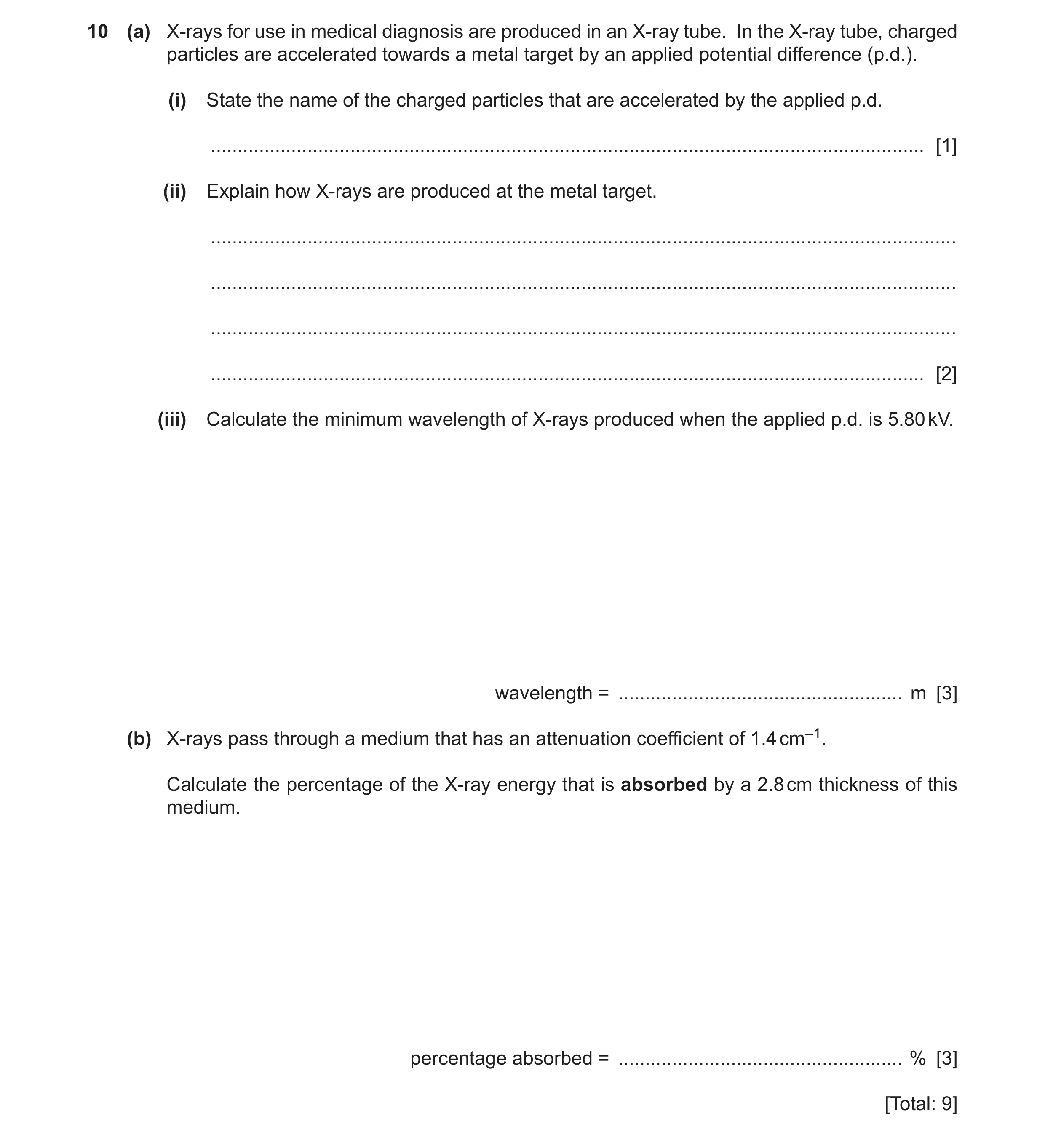
10 (a) X-rays for use in medical diagnosis are produced in an X-ray tube. In the X-ray tube, charged particles are accelerated towards a metal target by an applied potential difference (p.d.). (i) State the name of the charged particles that are accelerated by the applied p.d. … [1] (ii) Explain how X-rays are produced at the metal target. … … … … [2] (iii) Calculate the minimum wavelength of X-rays produced when the applied p.d. is 5.80 kV. wavelength = … m [3] (b) X-rays pass through a medium that has an attenuation coefficient of 1.4 cm–1. Calculate the percentage of the X-ray energy that is absorbed by a 2.8 cm thickness of this medium. percentage absorbed = … % [3] [Total: 9]
9 marks
Mark scheme: 10(a)(i) electrons B1 10(a)(ii) electrons are decelerated / stopped on impact with the target B1 (kinetic) energy lost by electrons emitted as (X-ray) photons B1 10(a)(iii) eV = hc / C1 = (6.63 10–34 3.00 108) / (1.60 10–19 5800) C1 = 2.14 10–10 m A1 10(b) I = I0 exp (–x) C1 IT / I0 = exp (–(1.4 2.8)) = 0.020 C1 % absorbed = (1.000 – 0.0198) 100 = 98% A1
This question in 9702/42 May/June 2023
Q26 · Ultrasound and X-rays are both types of wave that are used in medical diagnosis to form… 9702/41 Oct/Nov 2023
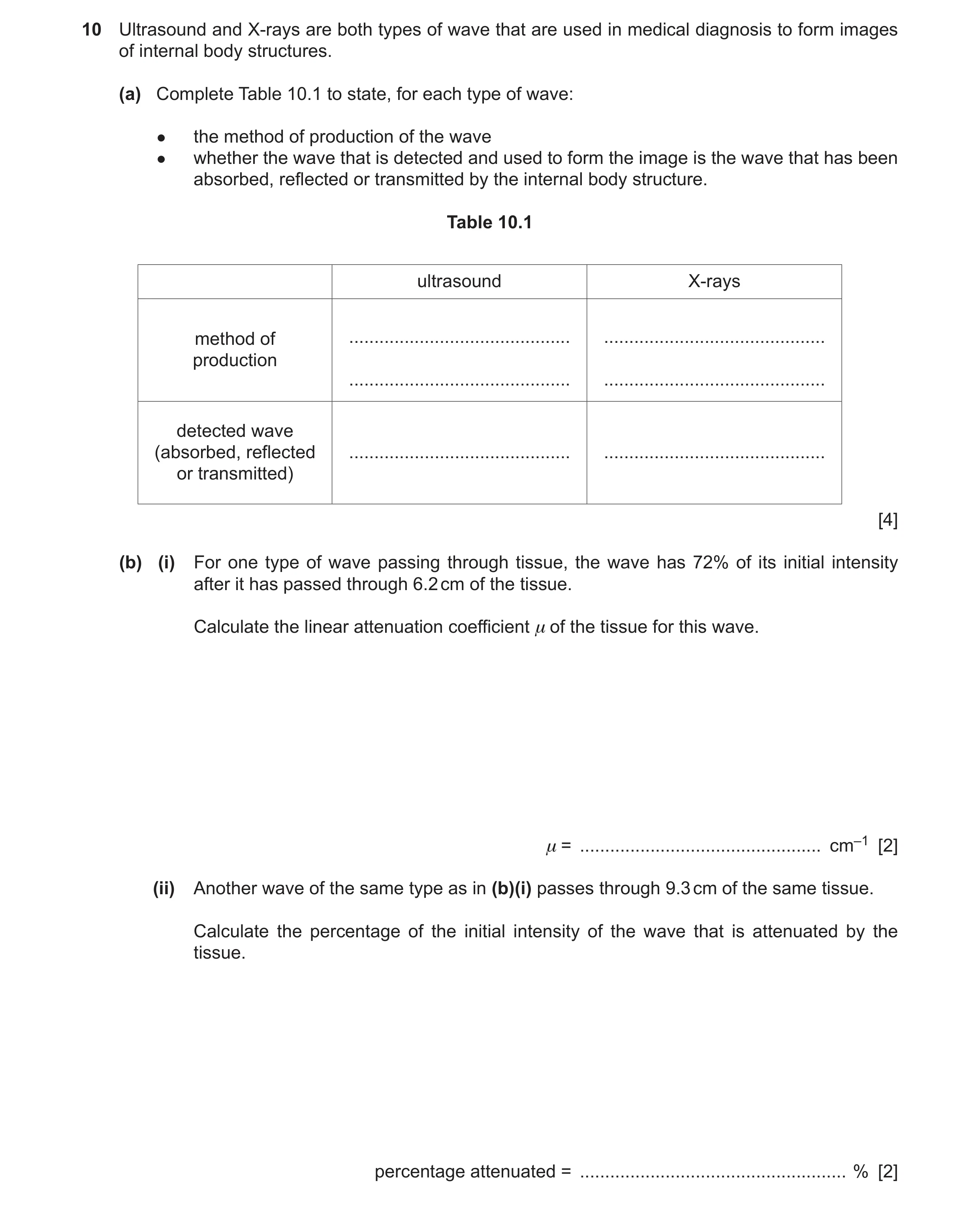
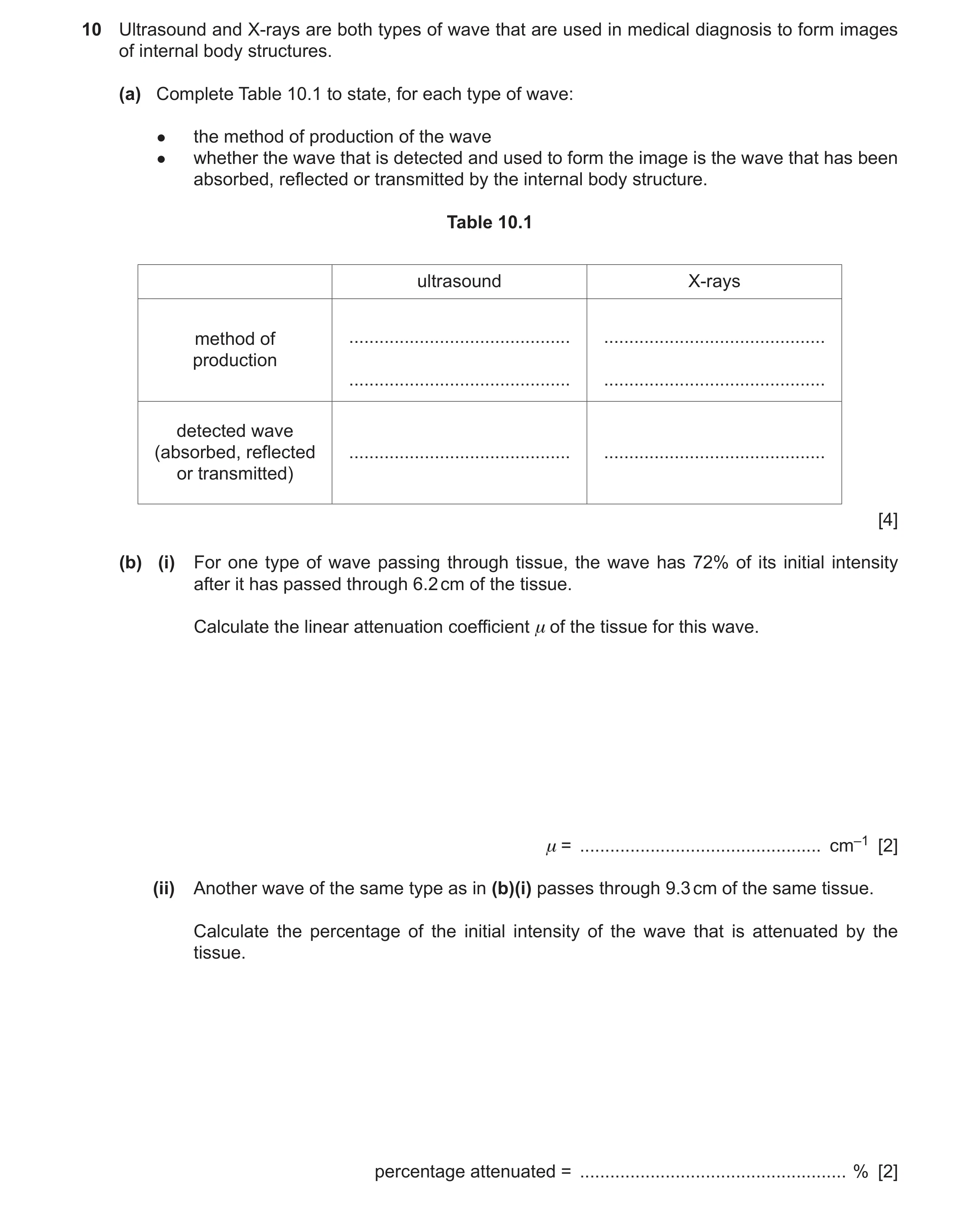
10 Ultrasound and X-rays are both types of wave that are used in medical diagnosis to form images of internal body structures. (a) Complete Table 10.1 to state, for each type of wave: ● the method of production of the wave ● whether the wave that is detected and used to form the image is the wave that has been absorbed, reflected or transmitted by the internal body structure. Table 10.1 ultrasound X-rays method of … … production … … detected wave (absorbed, reflected … … or transmitted) [4] (b) (i) For one type of wave passing through tissue, the wave has 72% of its initial intensity after it has passed through 6.2 cm of the tissue. Calculate the linear attenuation coefficient μ of the tissue for this wave. μ = … cm–1 [2] (ii) Another wave of the same type as in (b)(i) passes through 9.3 cm of the same tissue. Calculate the percentage of the initial intensity of the wave that is attenuated by the tissue. percentage attenuated = … % [2]
8 marks
Mark scheme: 10(a) ultrasound production: vibrating quartz crystal B1 X-ray production: electrons hitting metal target B1 ultrasound detected wave: reflected B1 X-ray detected wave: transmitted B1 10(b)(i) I = I0 exp (–x) C1 ln (0.72) = –6.2 A1 = 0.053 cm–1 10(b)(ii) I / I0 = exp (–9.3 0.053) C1 ( = 0.61) percentage attenuated = 100 (1.00 – 0.61) A1 = 39%
This question in 9702/41 Oct/Nov 2023
Q27 · Ultrasound and X-rays are both types of wave that are used in medical diagnosis to form… 9702/43 Oct/Nov 2023
10 Ultrasound and X-rays are both types of wave that are used in medical diagnosis to form images of internal body structures. (a) Complete Table 10.1 to state, for each type of wave: ● the method of production of the wave ● whether the wave that is detected and used to form the image is the wave that has been absorbed, reflected or transmitted by the internal body structure. Table 10.1 ultrasound X-rays method of … … production … … detected wave (absorbed, reflected … … or transmitted) [4] (b) (i) For one type of wave passing through tissue, the wave has 72% of its initial intensity after it has passed through 6.2 cm of the tissue. Calculate the linear attenuation coefficient μ of the tissue for this wave. μ = … cm–1 [2] (ii) Another wave of the same type as in (b)(i) passes through 9.3 cm of the same tissue. Calculate the percentage of the initial intensity of the wave that is attenuated by the tissue. percentage attenuated = … % [2]
8 marks
Mark scheme: 10(a) ultrasound production: vibrating quartz crystal B1 X-ray production: electrons hitting metal target B1 ultrasound detected wave: reflected B1 X-ray detected wave: transmitted B1 10(b)(i) I = I0 exp (–x) C1 ln (0.72) = –6.2 A1 = 0.053 cm–1 10(b)(ii) I / I0 = exp (–9.3 0.053) C1 ( = 0.61) percentage attenuated = 100 (1.00 – 0.61) A1 = 39%
This question in 9702/43 Oct/Nov 2023
Q28 · State what is meant by a photon 9702/41 May/June 2024
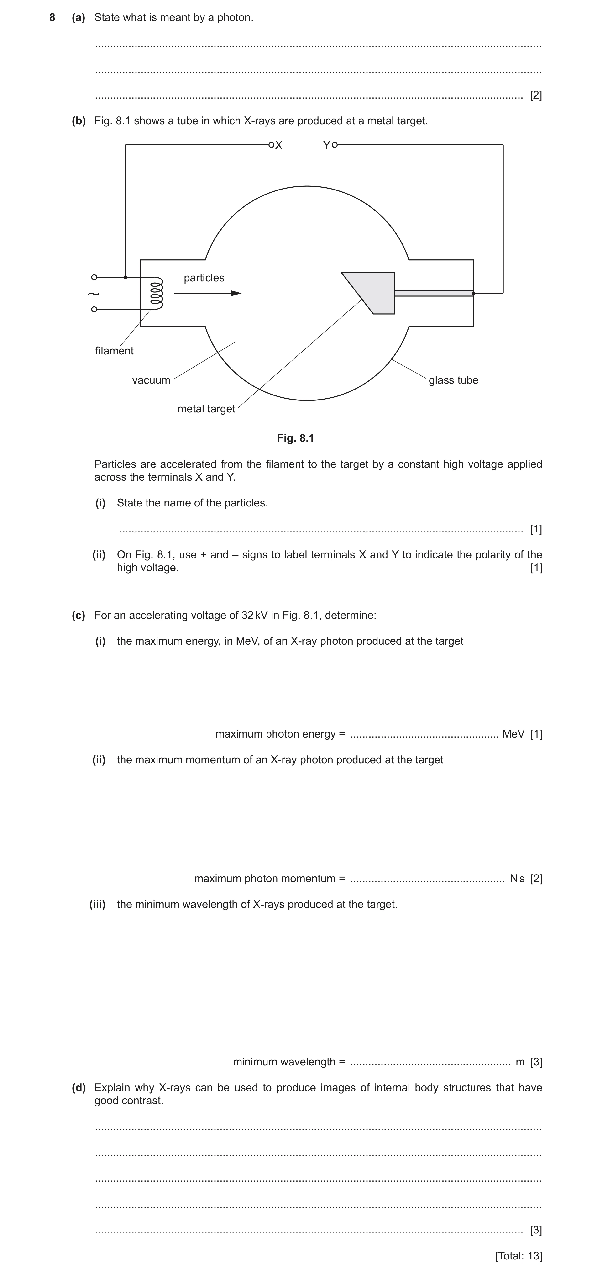
8 (a) State what is meant by a photon. … … … [2] (b) Fig. 8.1 shows a tube in which X-rays are produced at a metal target. X Y particles filament vacuum glass tube metal target Fig. 8.1 Particles are accelerated from the filament to the target by a constant high voltage applied across the terminals X and Y. (i) State the name of the particles. … [1] (ii) On Fig. 8.1, use + and – signs to label terminals X and Y to indicate the polarity of the high voltage. [1] (c) For an accelerating voltage of 32 kV in Fig. 8.1, determine: (i) the maximum energy, in MeV, of an X-ray photon produced at the target maximum photon energy = … MeV [1] (ii) the maximum momentum of an X-ray photon produced at the target maximum photon momentum = … N s [2] (iii) the minimum wavelength of X-rays produced at the target. minimum wavelength = … m [3] (d) Explain why X-rays can be used to produce images of internal body structures that have good contrast. … … … … … [3] [Total: 13]
13 marks
Mark scheme: 8(a) packet / quantum of energy M1 of electromagnetic radiation A1 8(b)(i) electron(s) B1 8(b)(ii) X labelled – and Y labelled + B1 8(c)(i) 0.032 MeV A1 8(c)(ii) momentum = E / c C1 momentum = (0.032 × 1.60 10–13) / (3.00 108) = 1.7 10–23 N s A1 8(c)(iii) E = hf and = c / f C1 = hc / E = (6.63 10–34 × 3.00 108) / (0.032 1.60 × 10⁻¹³) C1 = 3.9 10–11 m A1 8(d) discussion of bone and soft tissue B1 discussion of different attenuation (coefficients) or discussion differences in penetration / transmission / absorption B1 transmitted intensities (by bone and tissue) are very different (leading to good contrast images) B1
This question in 9702/41 May/June 2024
Q29 · State what is meant by a photon 9702/43 May/June 2024
8 (a) State what is meant by a photon. … … … [2] (b) Fig. 8.1 shows a tube in which X-rays are produced at a metal target. X Y particles filament vacuum glass tube metal target Fig. 8.1 Particles are accelerated from the filament to the target by a constant high voltage applied across the terminals X and Y. (i) State the name of the particles. … [1] (ii) On Fig. 8.1, use + and – signs to label terminals X and Y to indicate the polarity of the high voltage. [1] (c) For an accelerating voltage of 32 kV in Fig. 8.1, determine: (i) the maximum energy, in MeV, of an X-ray photon produced at the target maximum photon energy = … MeV [1] (ii) the maximum momentum of an X-ray photon produced at the target maximum photon momentum = … N s [2] (iii) the minimum wavelength of X-rays produced at the target. minimum wavelength = … m [3] (d) Explain why X-rays can be used to produce images of internal body structures that have good contrast. … … … … … [3] [Total: 13]
13 marks
Mark scheme: 8(a) packet / quantum of energy M1 of electromagnetic radiation A1 8(b)(i) electron(s) B1 8(b)(ii) X labelled – and Y labelled + B1 8(c)(i) 0.032 MeV A1 8(c)(ii) momentum = E / c C1 momentum = (0.032 × 1.60 10–13) / (3.00 108) = 1.7 10–23 N s A1 8(c)(iii) E = hf and = c / f C1 = hc / E = (6.63 10–34 × 3.00 108) / (0.032 1.60 × 10⁻¹³) C1 = 3.9 10–11 m A1 8(d) discussion of bone and soft tissue B1 discussion of different attenuation (coefficients) or discussion differences in penetration / transmission / absorption B1 transmitted intensities (by bone and tissue) are very different (leading to good contrast images) B1
This question in 9702/43 May/June 2024
Q30 · Two parallel metal plates X and Y are separated by a distance of 0.041 m, as shown in Fig 9702/42 May/June 2025
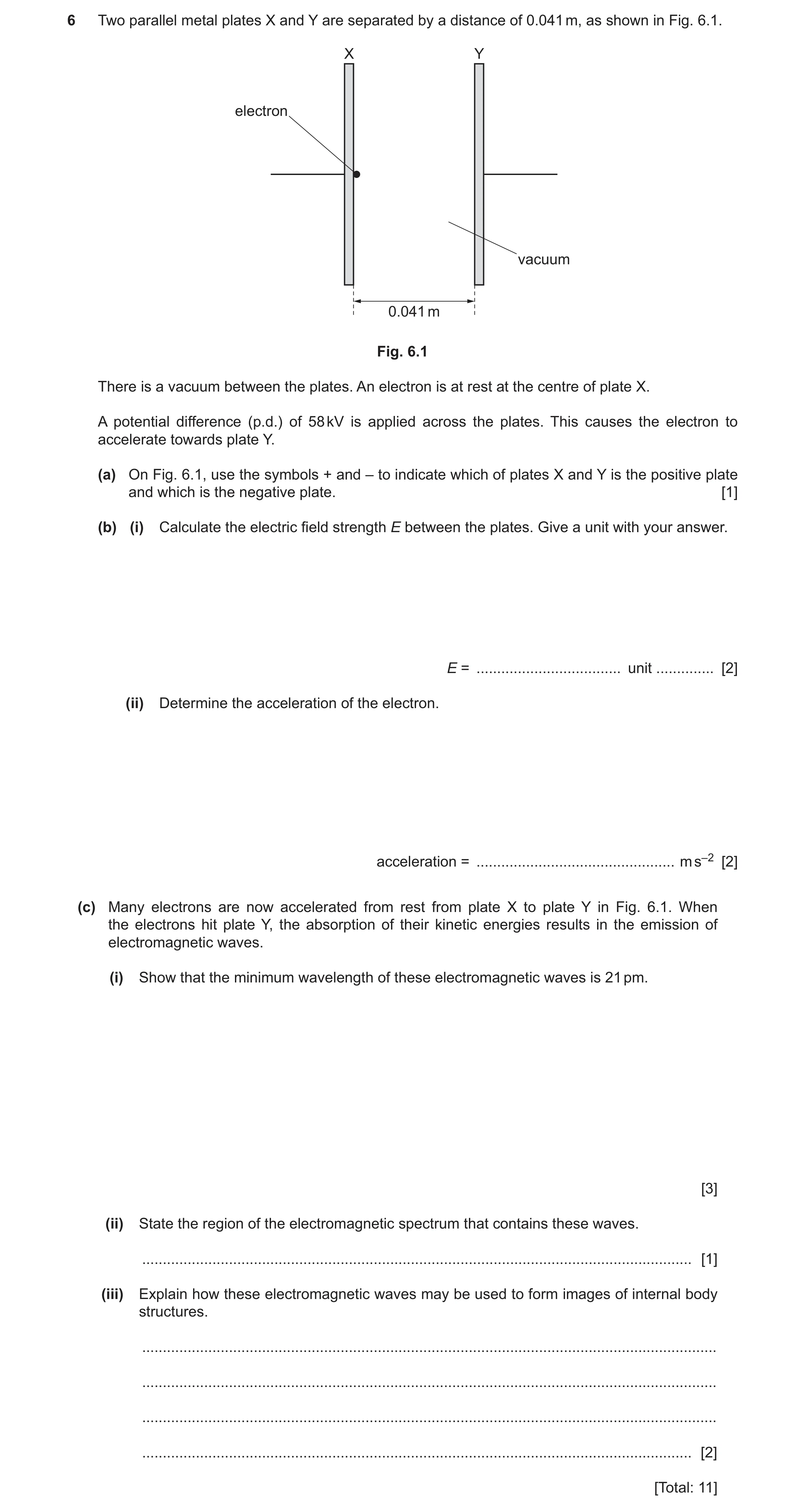
6 Two parallel metal plates X and Y are separated by a distance of 0.041 m, as shown in Fig. 6.1. X Y electron vacuum 0.041 m Fig. 6.1 There is a vacuum between the plates. An electron is at rest at the centre of plate X. A potential difference (p.d.) of 58 kV is applied across the plates. This causes the electron to accelerate towards plate Y. (a) On Fig. 6.1, use the symbols + and – to indicate which of plates X and Y is the positive plate and which is the negative plate. [1] (b) (i) Calculate the electric field strength E between the plates. Give a unit with your answer. E = … unit … [2] (ii) Determine the acceleration of the electron. acceleration = … m s–2 [2] (c) Many electrons are now accelerated from rest from plate X to plate Y in Fig. 6.1. When the electrons hit plate Y, the absorption of their kinetic energies results in the emission of electromagnetic waves. (i) Show that the minimum wavelength of these electromagnetic waves is 21 pm. [3] (ii) State the region of the electromagnetic spectrum that contains these waves. … [1] (iii) Explain how these electromagnetic waves may be used to form images of internal body structures. … … … … [2] [Total: 11]
11 marks
Mark scheme: 6(a) plate X marked as negative and plate Y marked as positive B1 6(b)(i) E = V / x C1 = (58 × 103) / 0.041 A1 = 1.4 × 10⁶ N C–1 6(b)(ii) ma = eE C1 a = (1.60 × 10–19 × 1.41 × 106) / (9.11 × 10⁻³¹) A1 = 2.5 × 10¹⁷ m s–2 6(c)(i) eV = hc / C1 or eV = hf and f = c / (1.60 × 10–19 × 58 × 103) = (6.63 × 10–34 × 3.00 × 108) / M1 clear conversion from m to pm leading to = 21 pm A1 6(c)(ii) X-rays B1 6(c)(iii) Any two points from: B2 • waves are passed into structure and transmitted waves detected • different parts of the structure absorb different fractions of energy • difference in detected / transmitted intensities used (to form image)
This question in 9702/42 May/June 2025
Q31 · State what is meant by contrast in an X-ray image 9702/42 Oct/Nov 2025
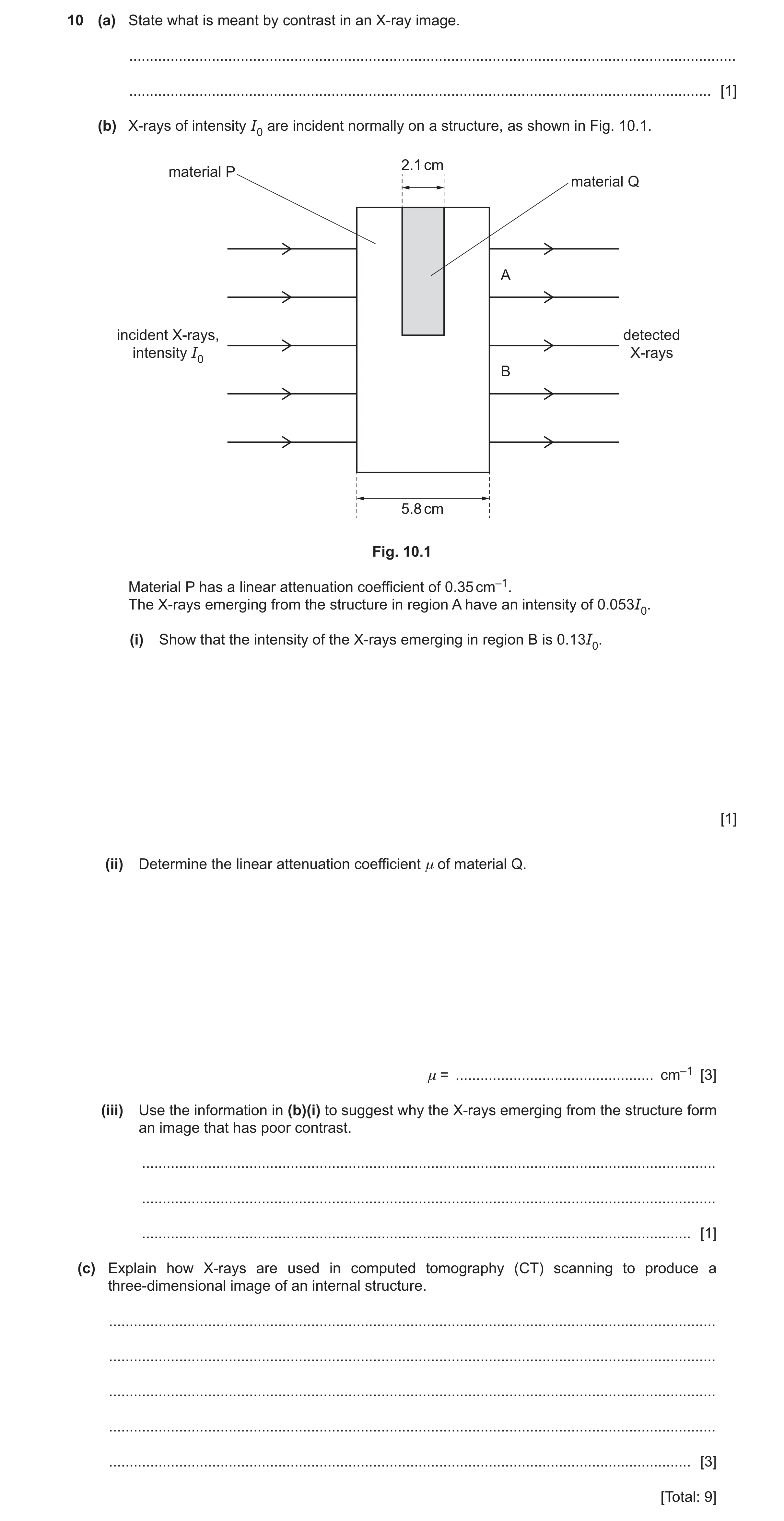
10 (a) State what is meant by contrast in an X-ray image. … … [1] (b) X-rays of intensity I0 are incident normally on a structure, as shown in Fig. 10.1. 2.1 cm material P material Q A incident X-rays, detected intensity I0 X-rays B 5.8 cm Fig. 10.1 Material P has a linear attenuation coefficient of 0.35 cm–1. The X-rays emerging from the structure in region A have an intensity of 0.053I0. (i) Show that the intensity of the X-rays emerging in region B is 0.13I0. [1] (ii) Determine the linear attenuation coefficient μ of material Q. μ = … cm–1 [3] (iii) Use the information in (b)(i) to suggest why the X-rays emerging from the structure form an image that has poor contrast. … … … [1] (c) Explain how X-rays are used in computed tomography (CT) scanning to produce a three-dimensional image of an internal structure. … … … … … [3] [Total: 9]
9 marks
Mark scheme: 10(a) difference in degrees of blackening B1 10(b)(i) I = I0 exp (–x) A1 = I0 exp (– 5.8 0.35) = 0.13 I0 10(b)(ii) use of exp {–(0.35 3.7)} factor C1 0.053I0 = I0 exp {–[(0.35 3.7) + 2.1]} C1 = 0.78 cm–1 A1 10(b)(iii) factor of only 2.5 between the (detected) intensities (so not good contrast) B1 10(c) (structure) scanned in (thin) sections B1 (many) scans (of each section) taken from different angles B1 scanning repeated for all sections and (data) compiled (to form 3D image) B1
This question in 9702/42 Oct/Nov 2025
 1 / 38
 2 / 38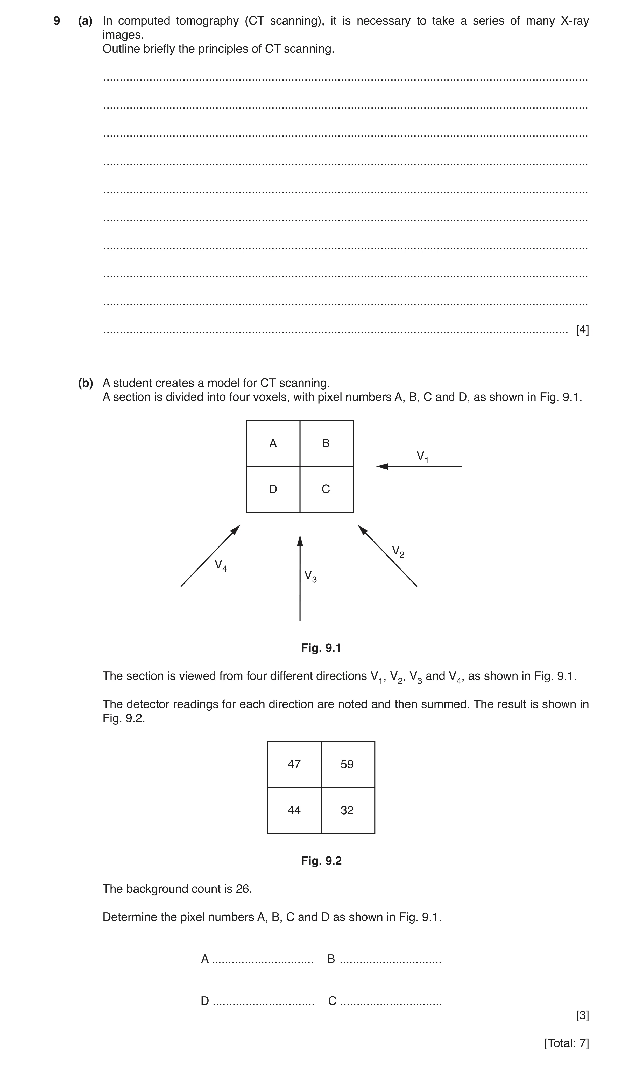
 8 / 38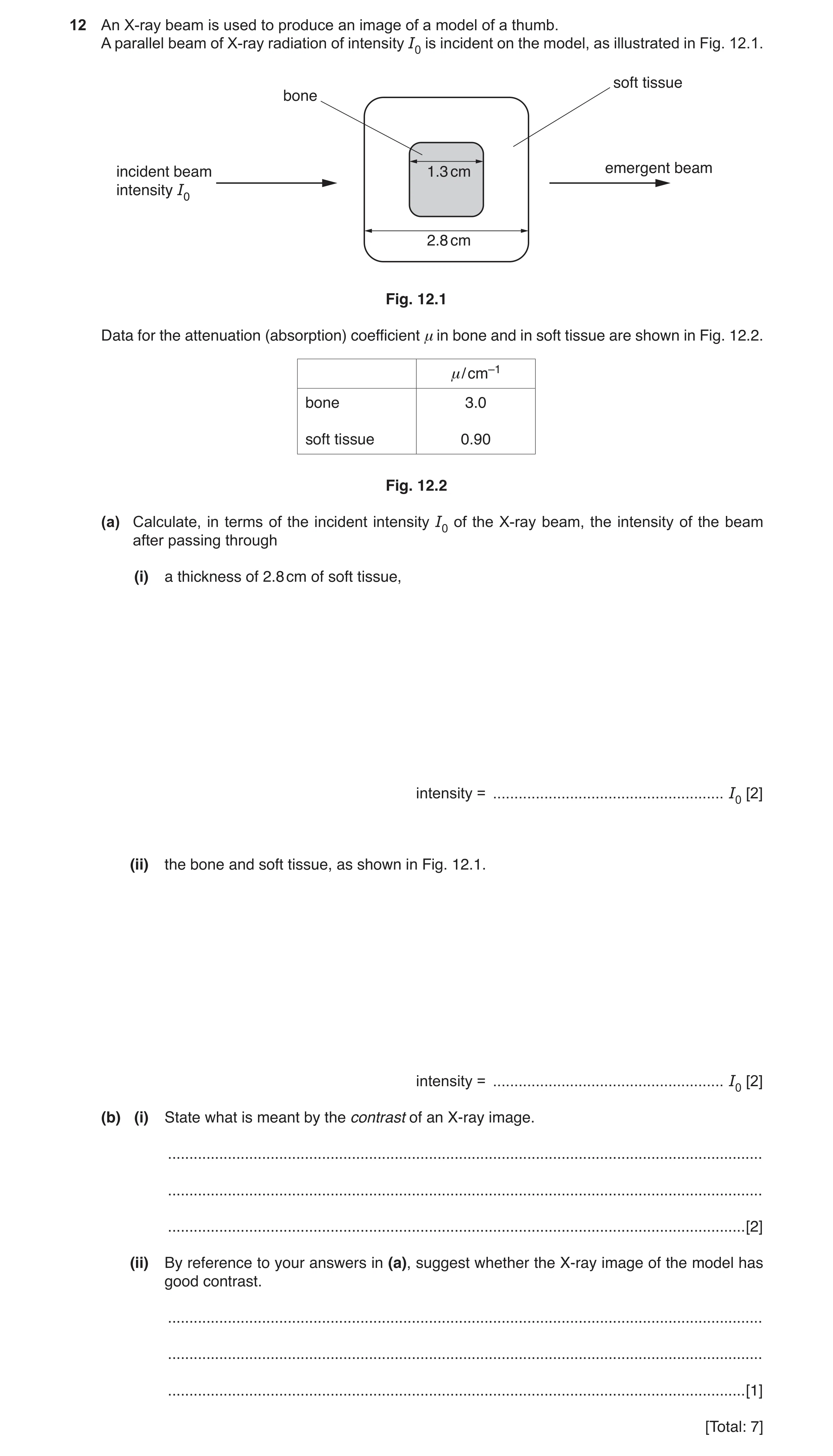
 11 / 38
 12 / 38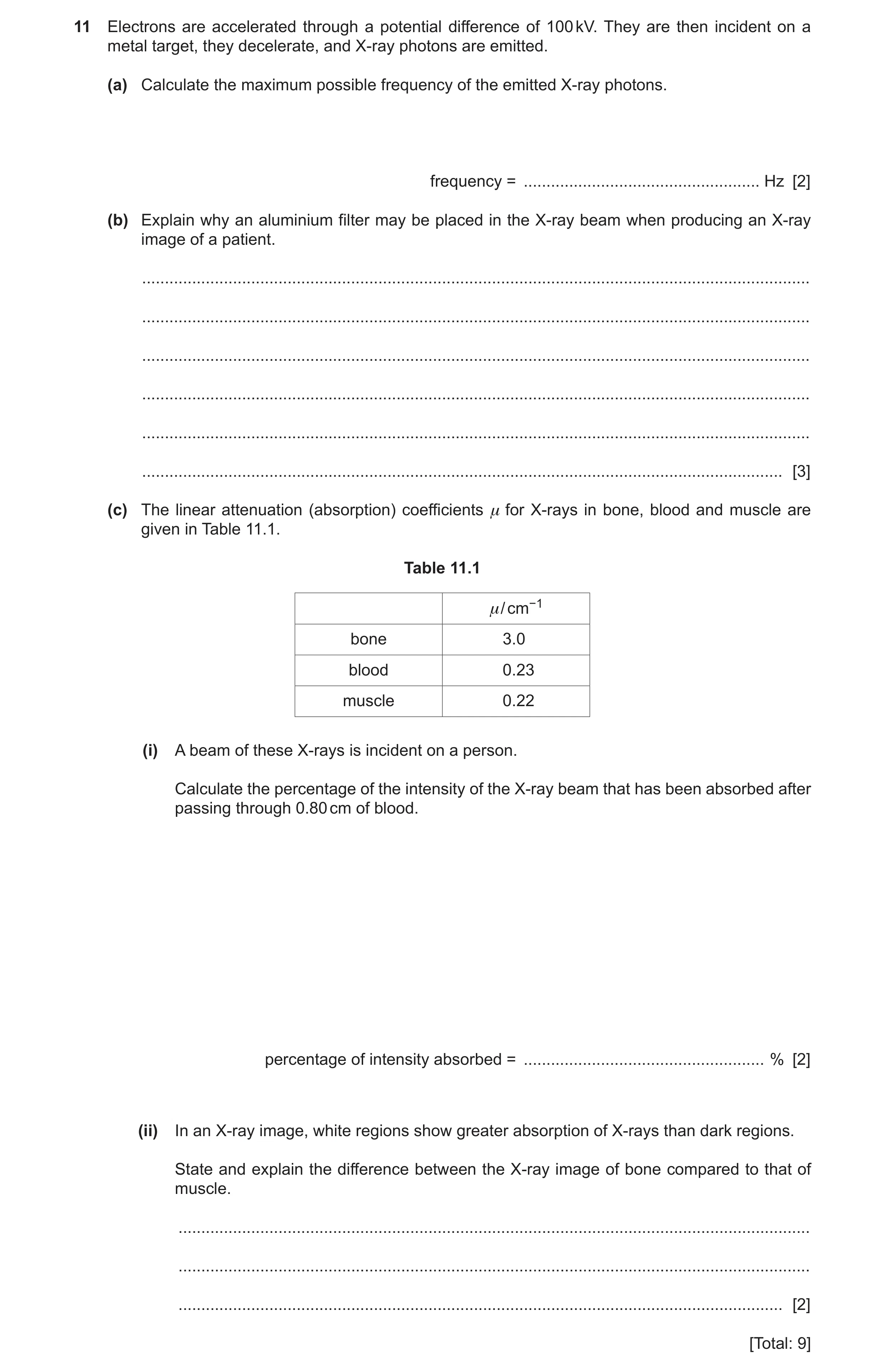
 15 / 38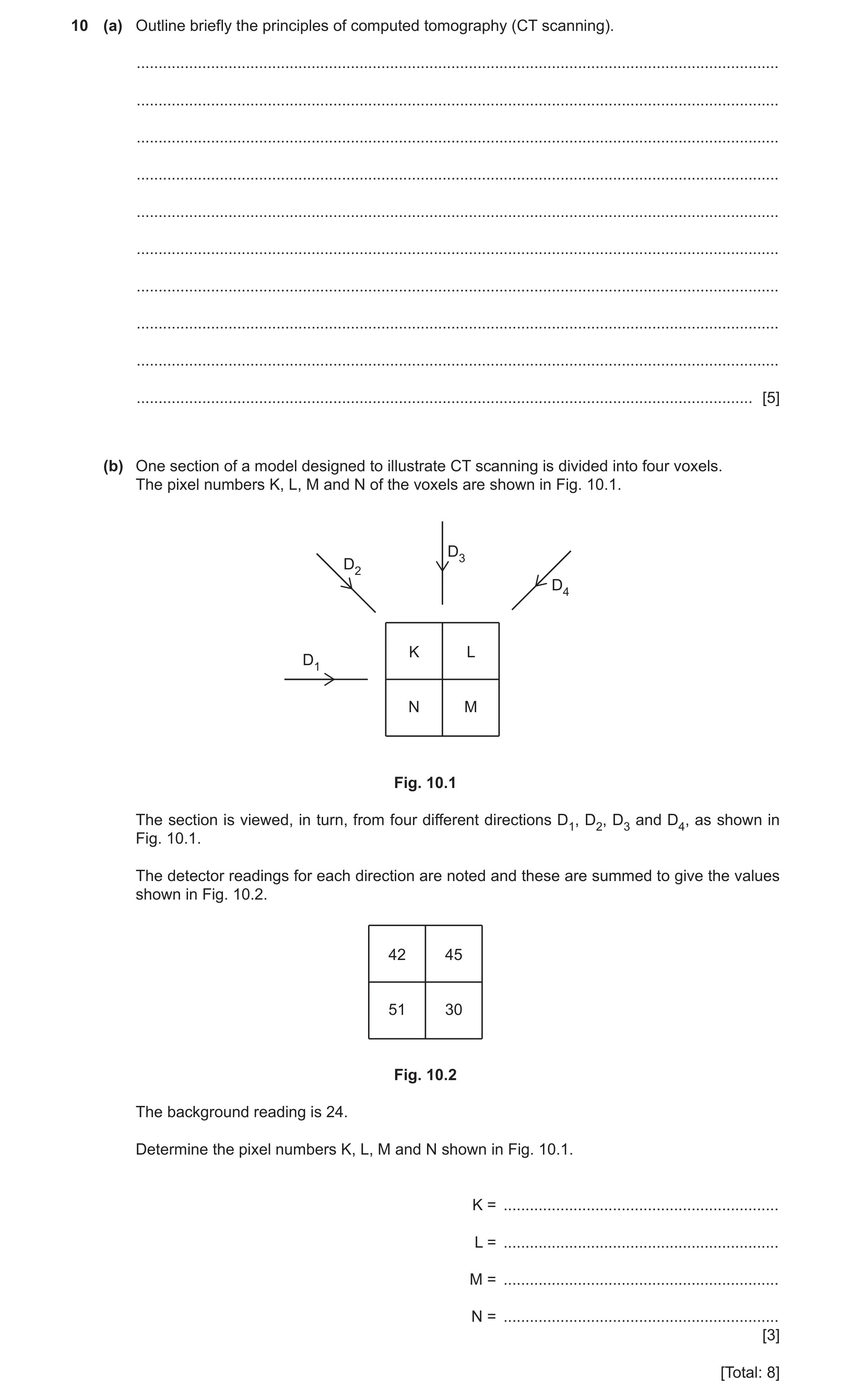
 20 / 38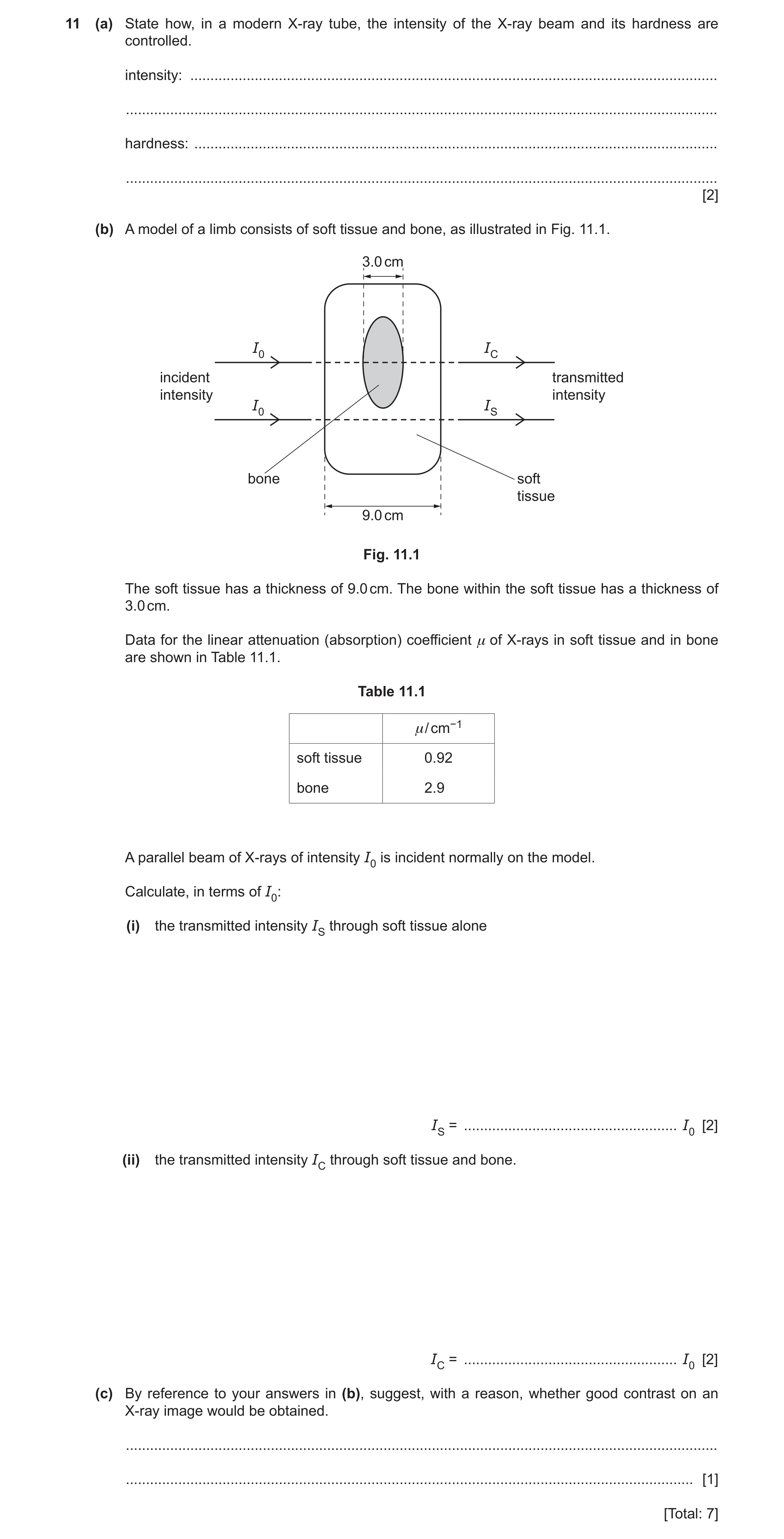
 23 / 38
 24 / 38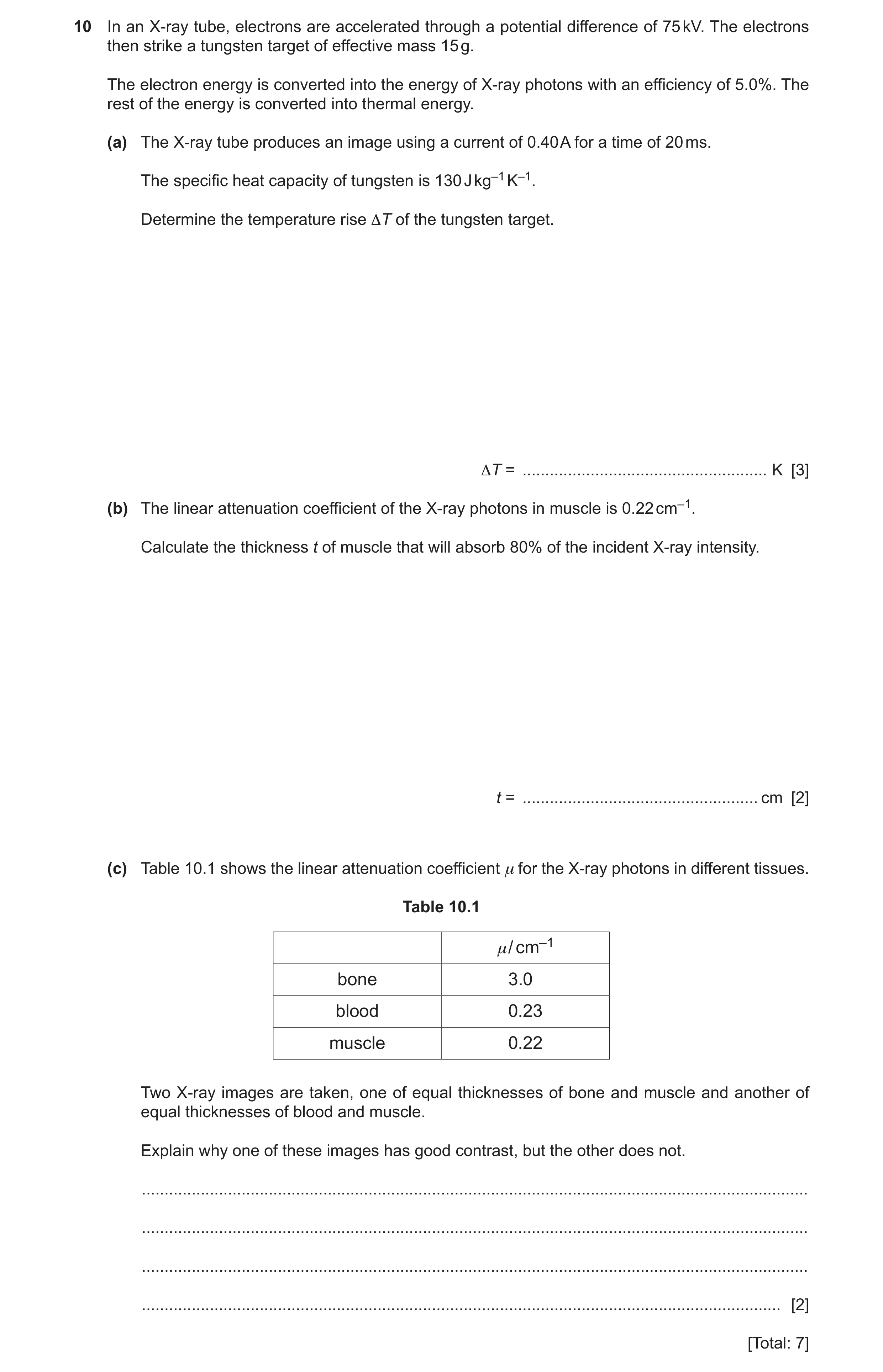
 29 / 38
 30 / 38
 31 / 38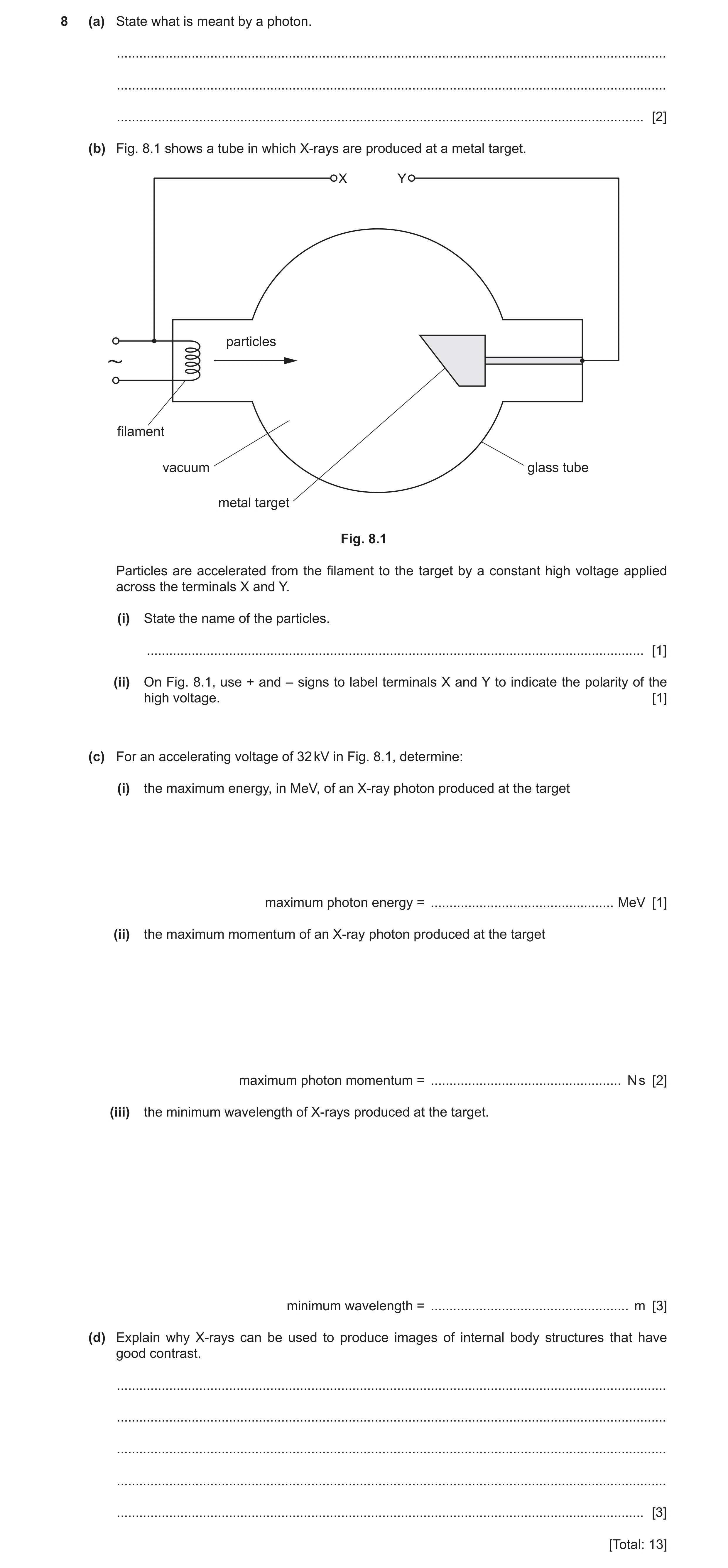
 5
5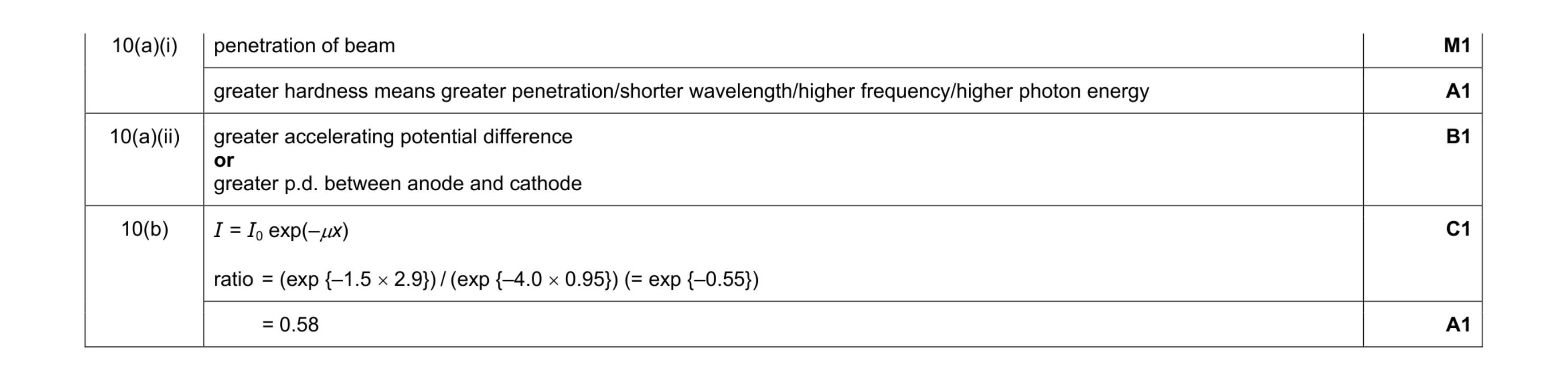 5
5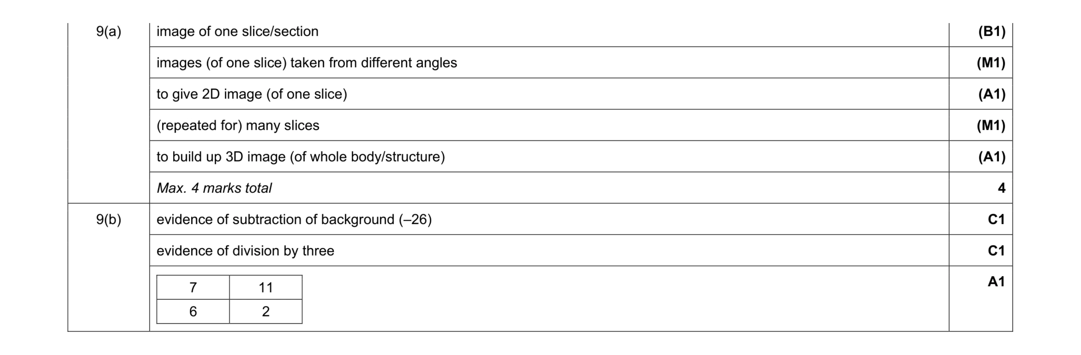 7
7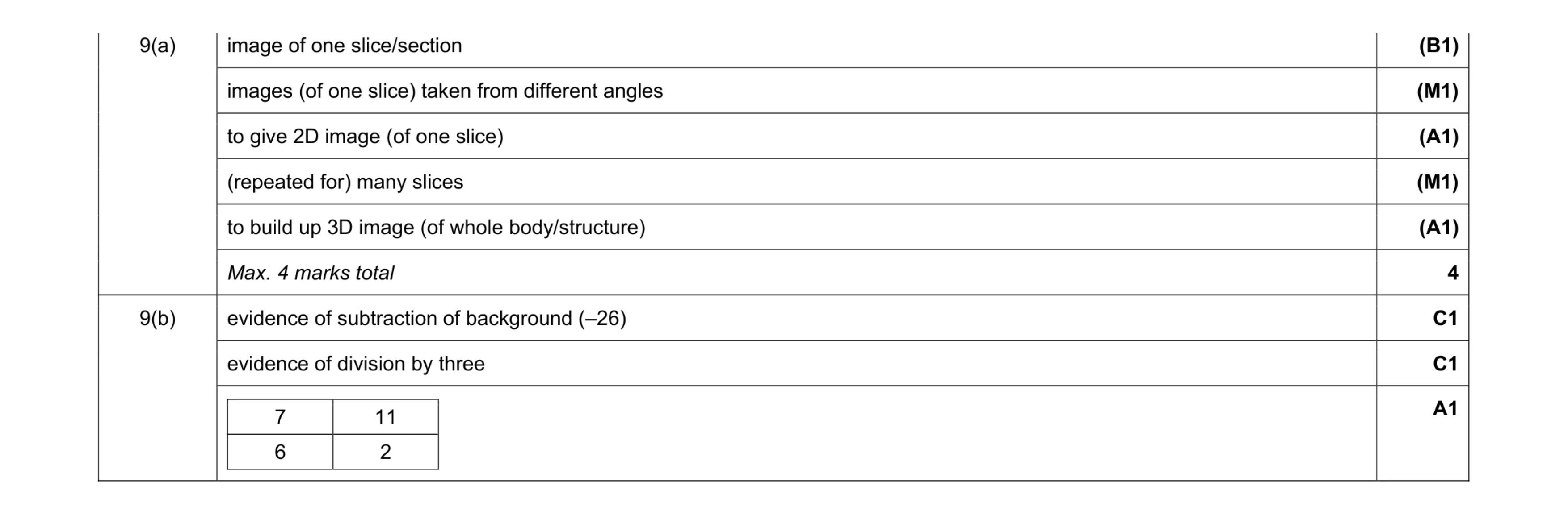 7
7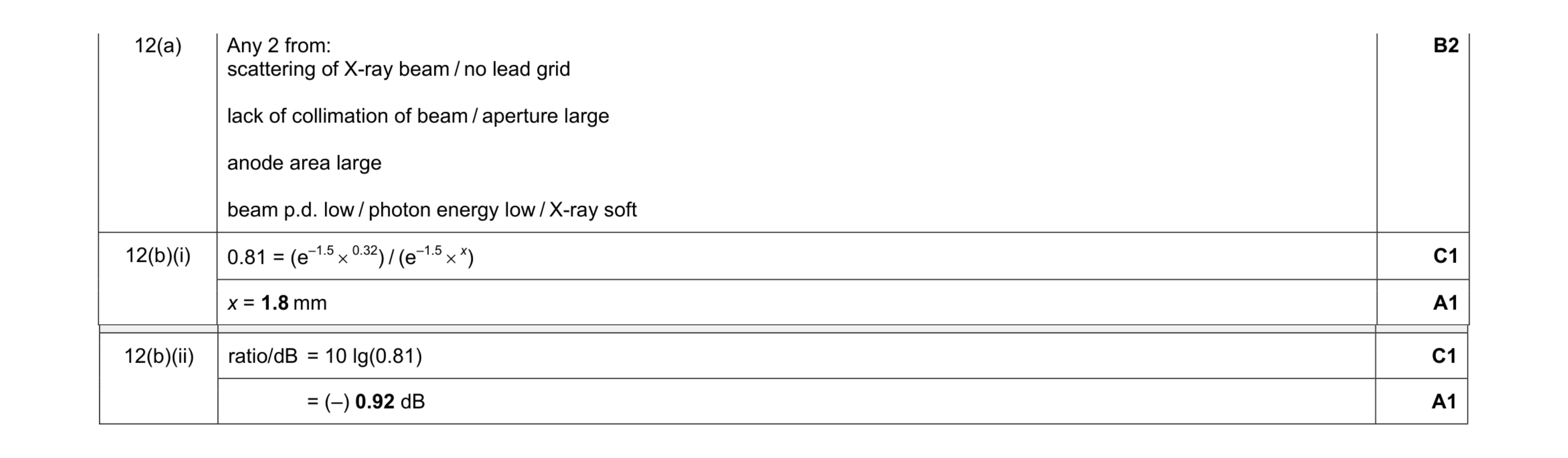 6
6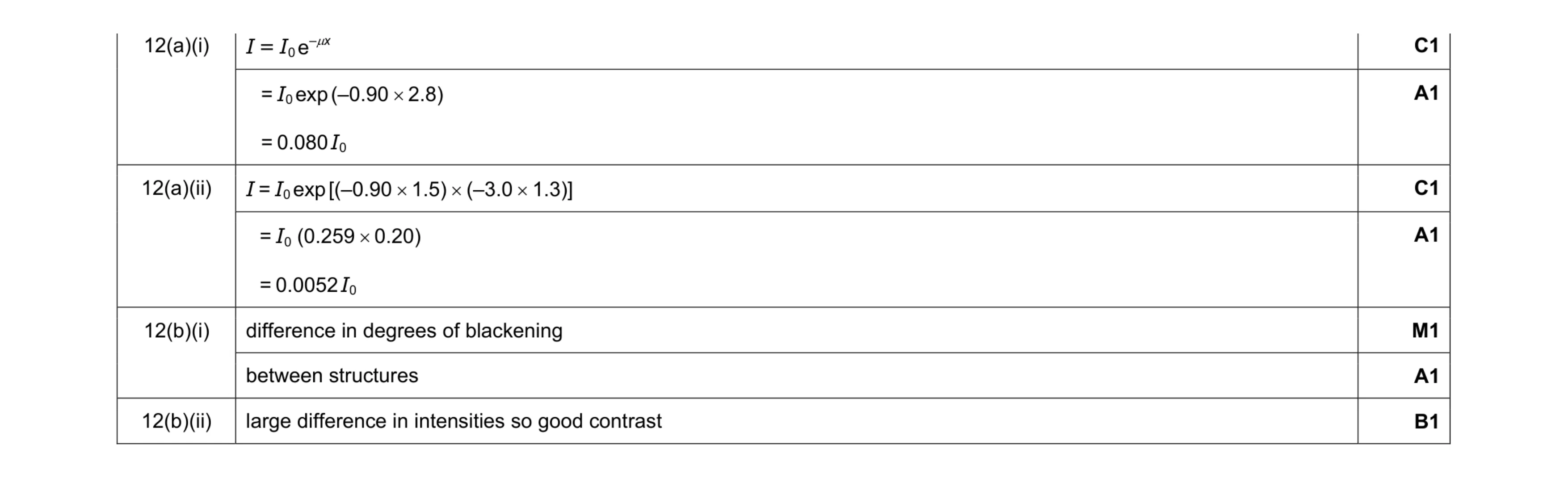 7
7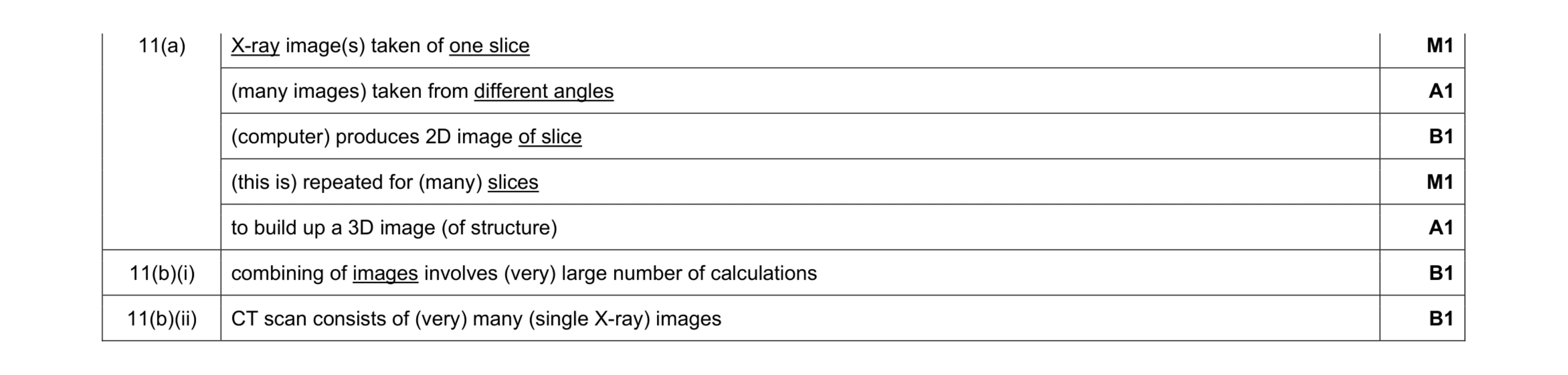 7
7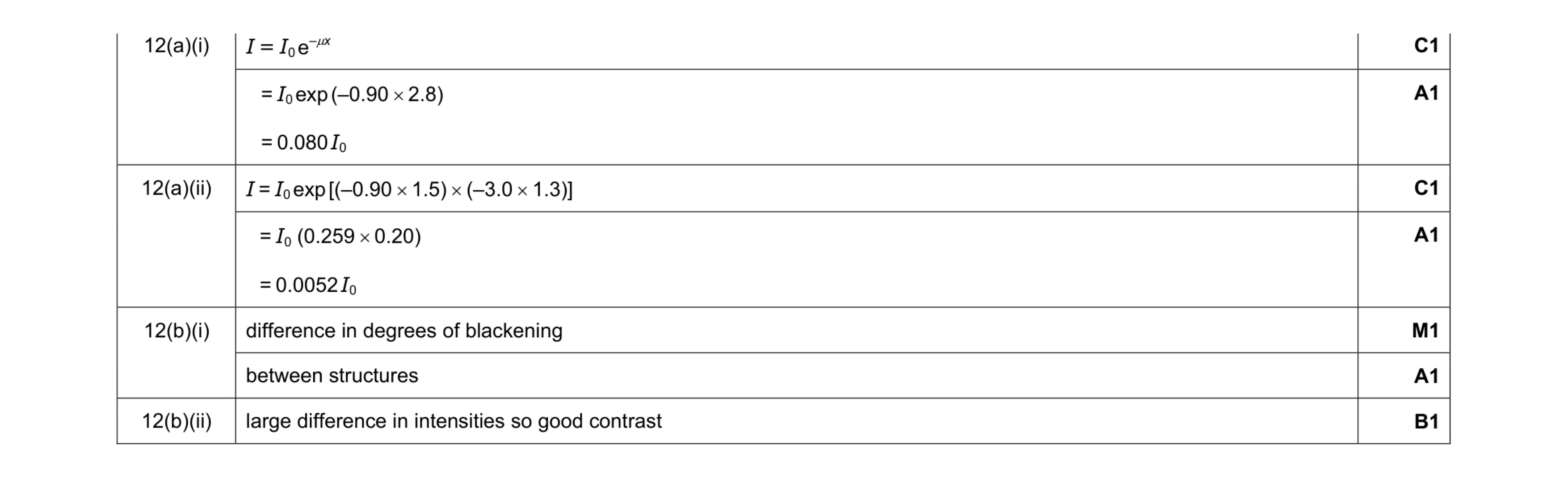 7
7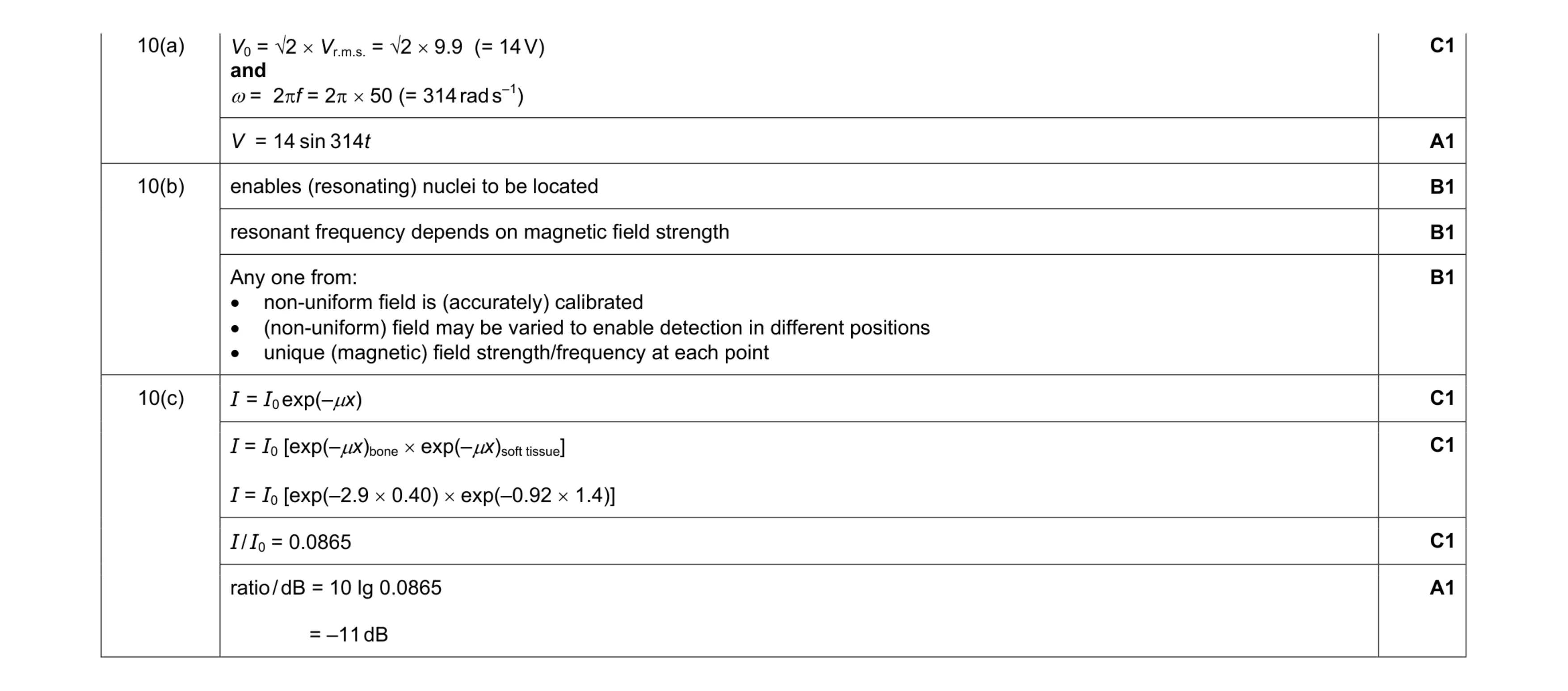 9
9 5
5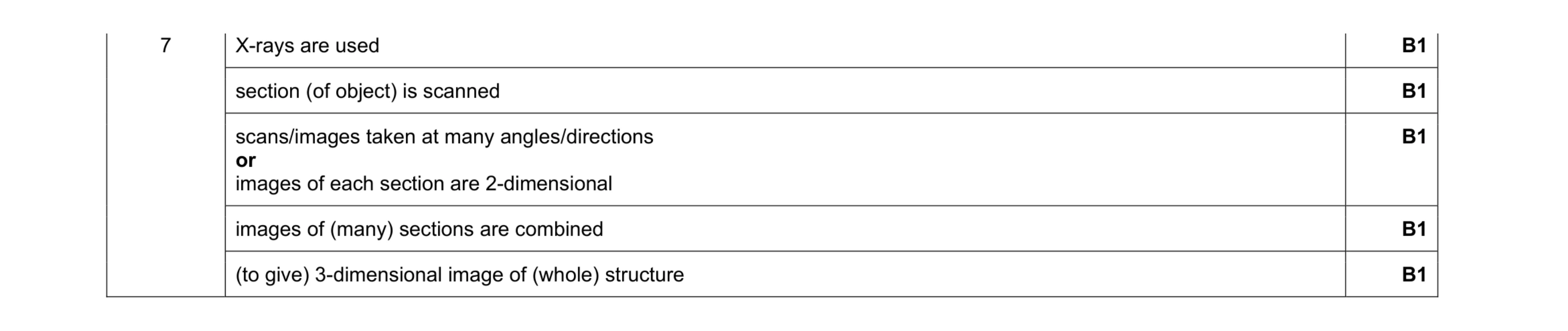 5
5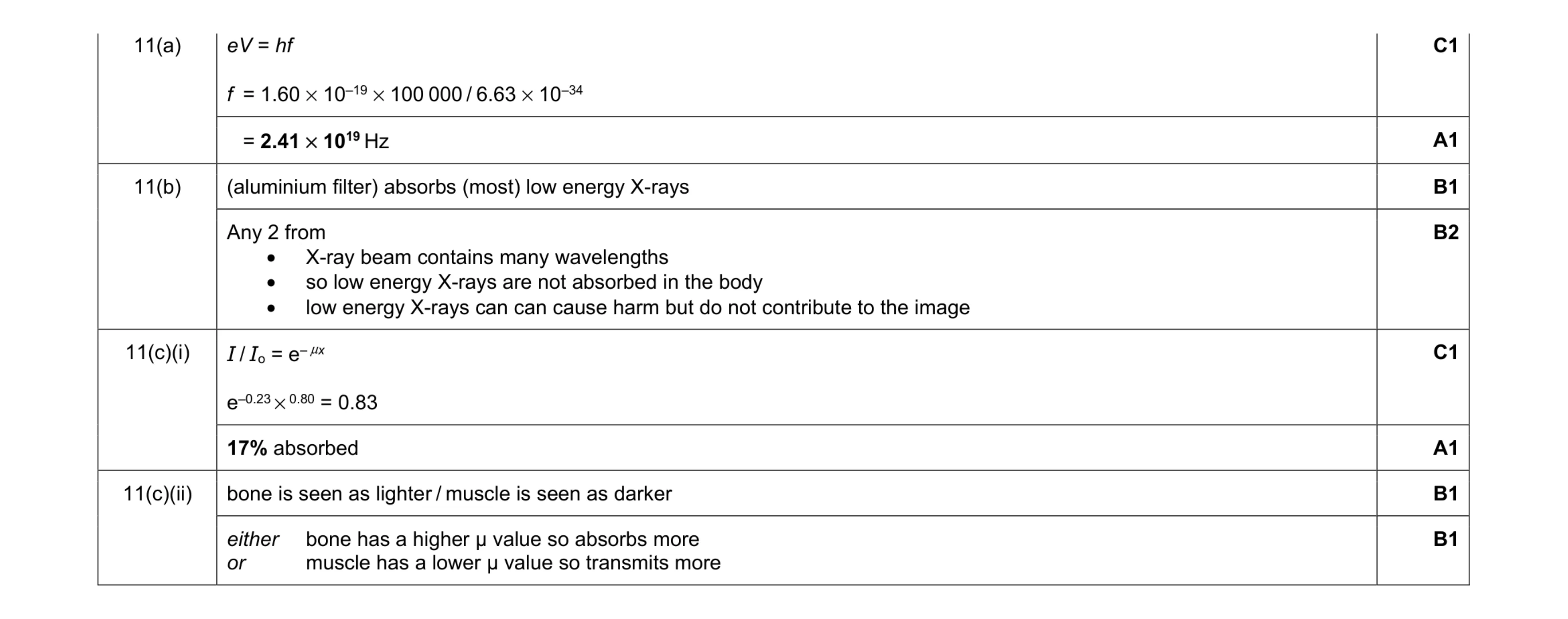 9
9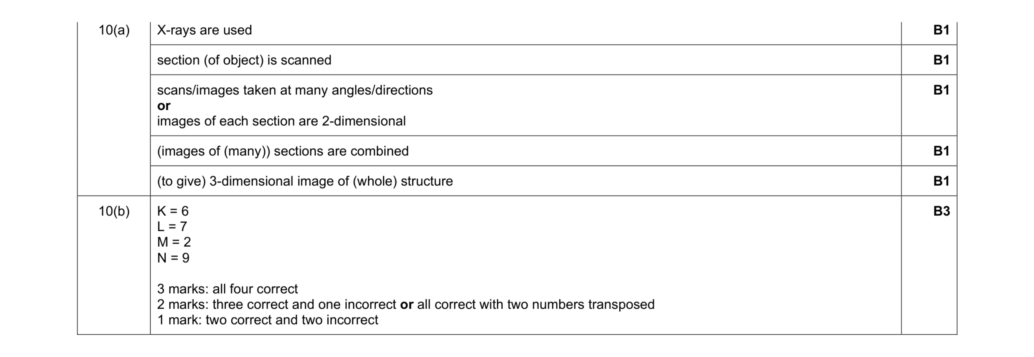 8
8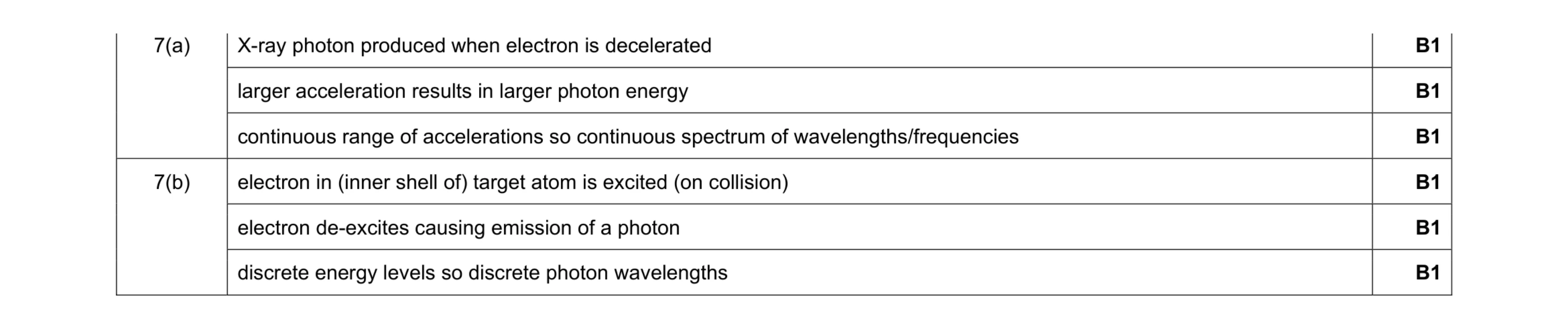 6
6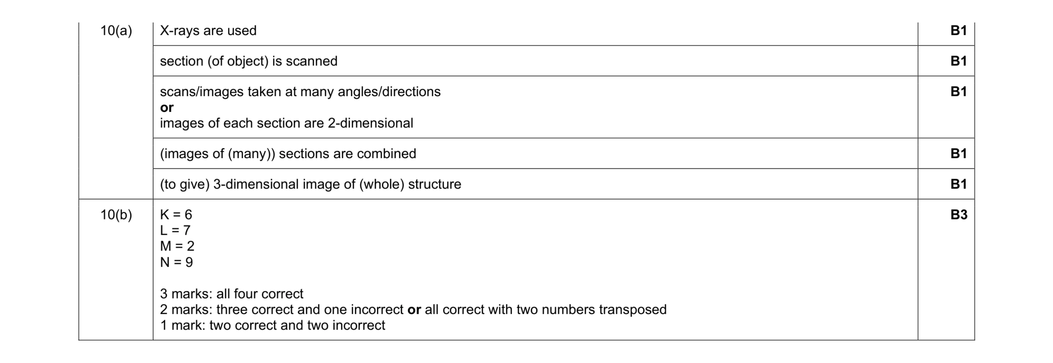 8
8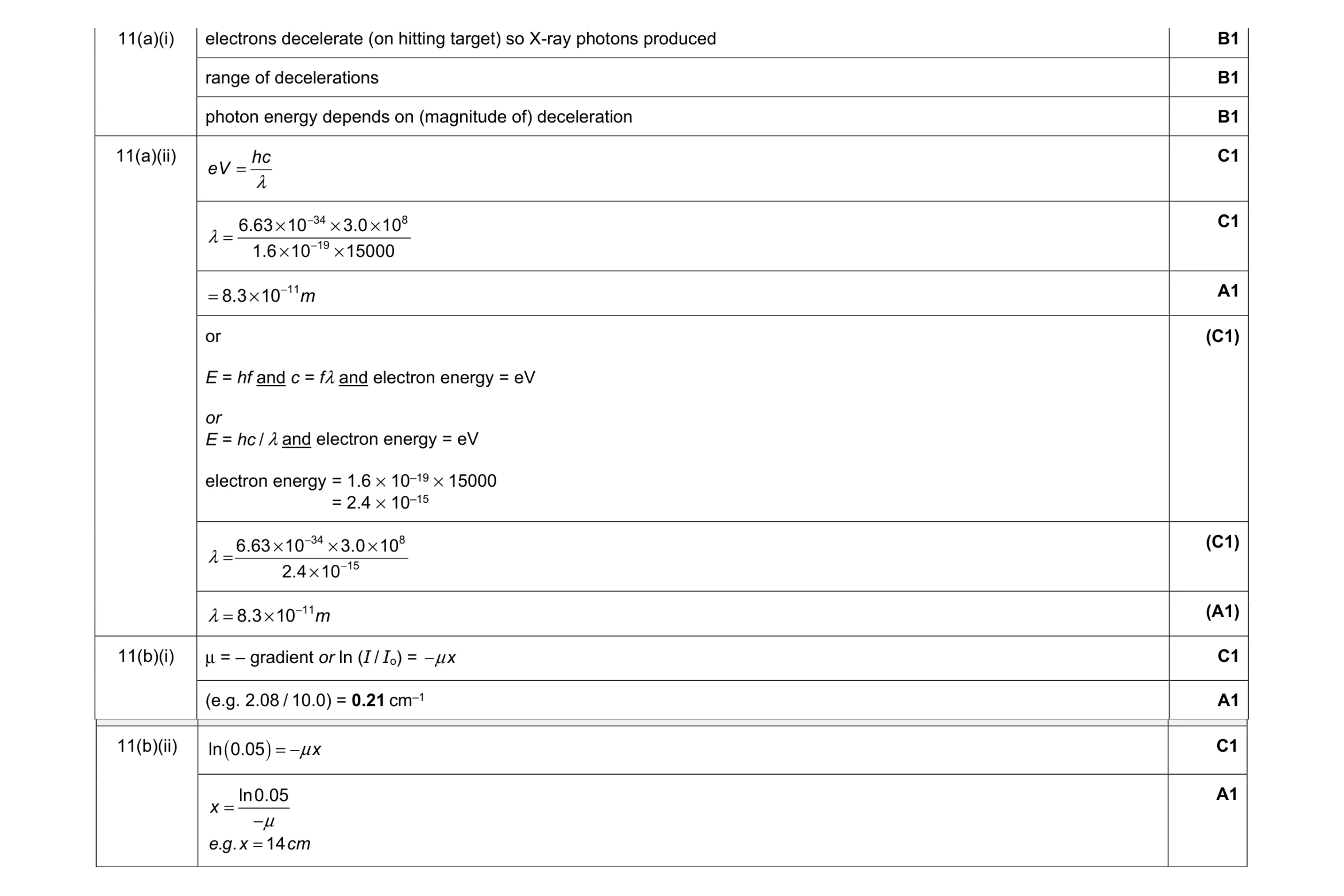 10
10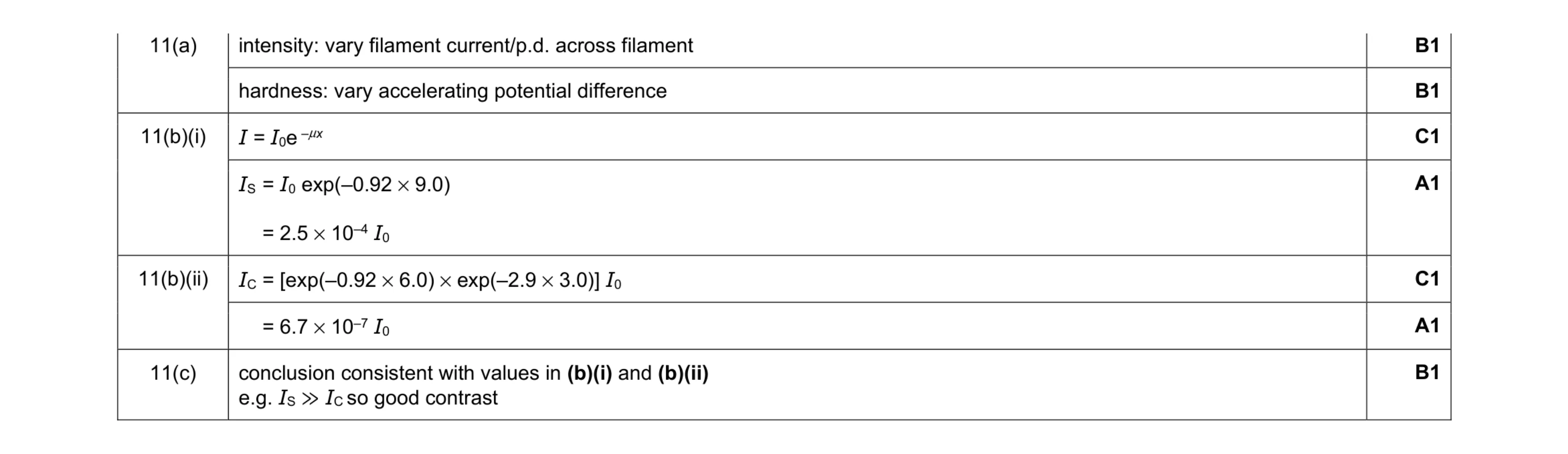 7
7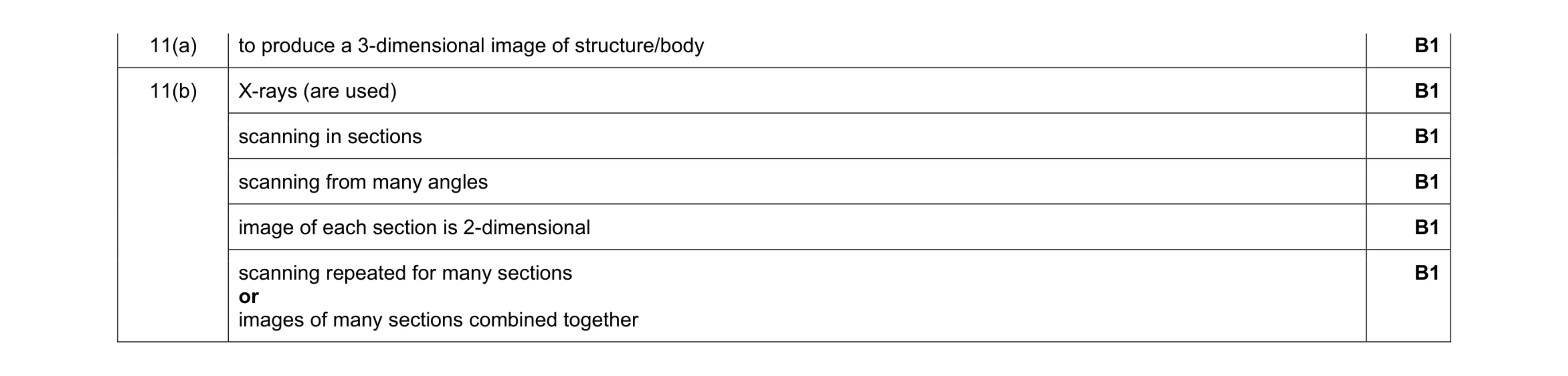 6
6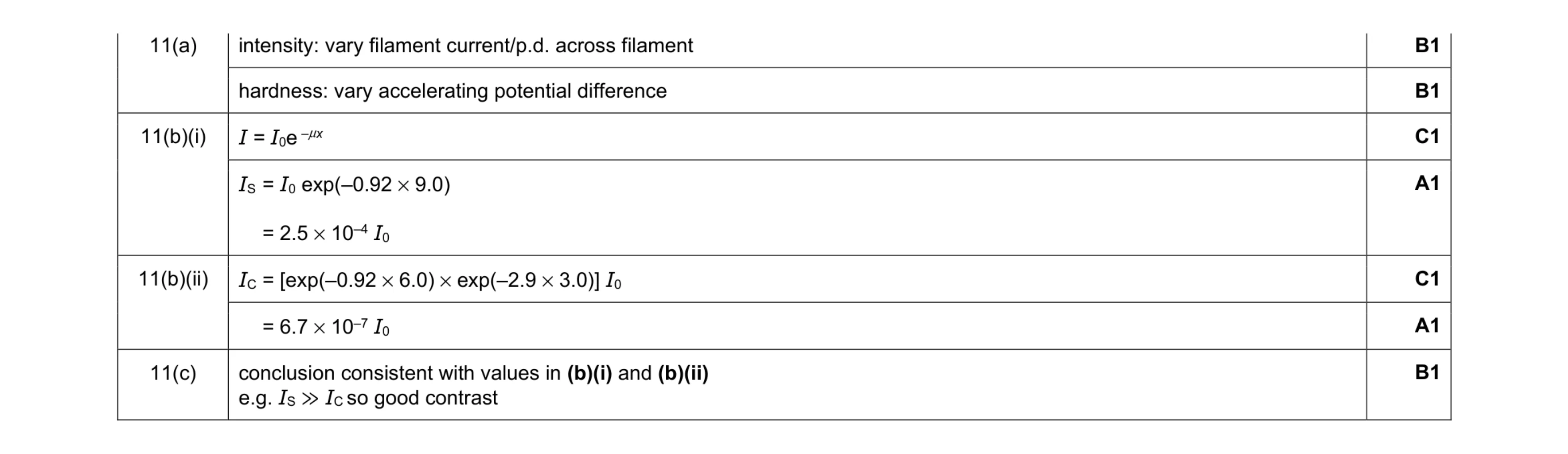 7
7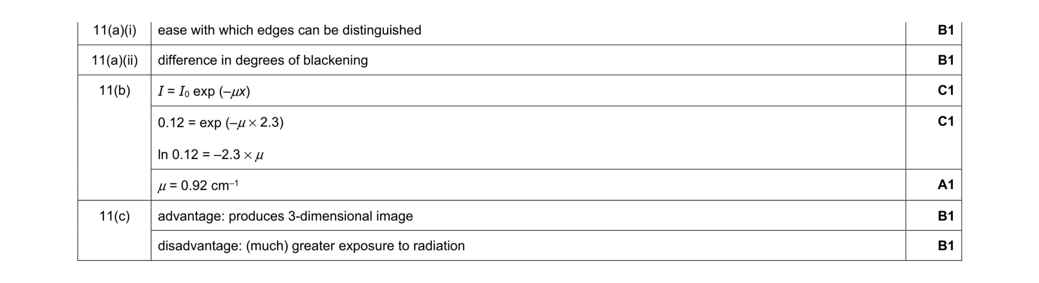 7
7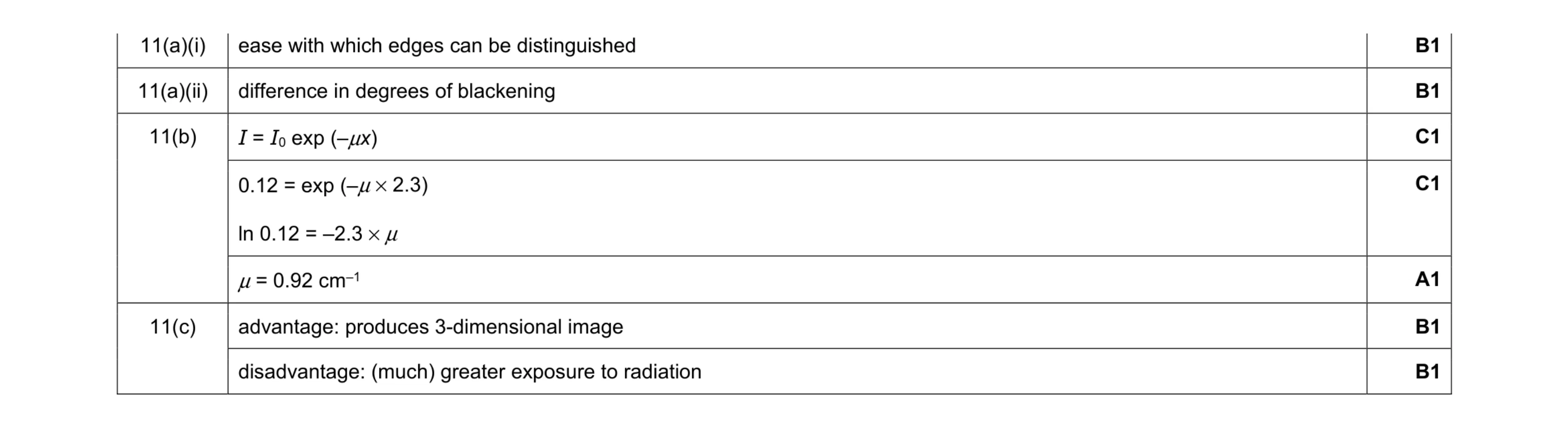 7
7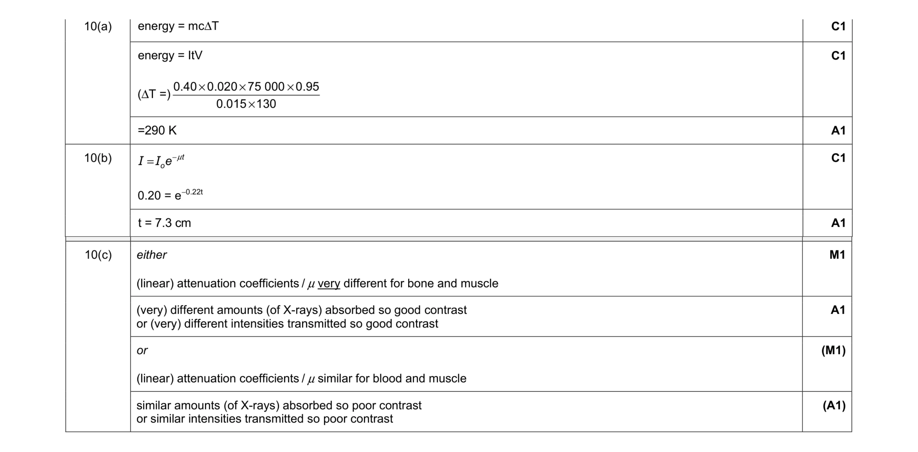 7
7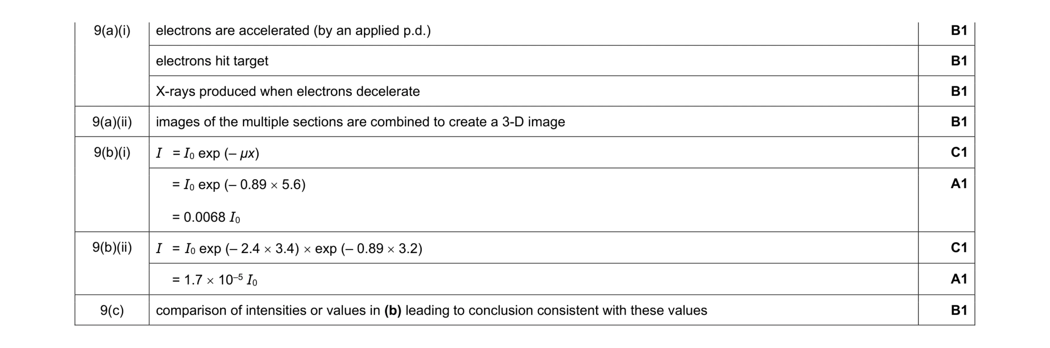 9
9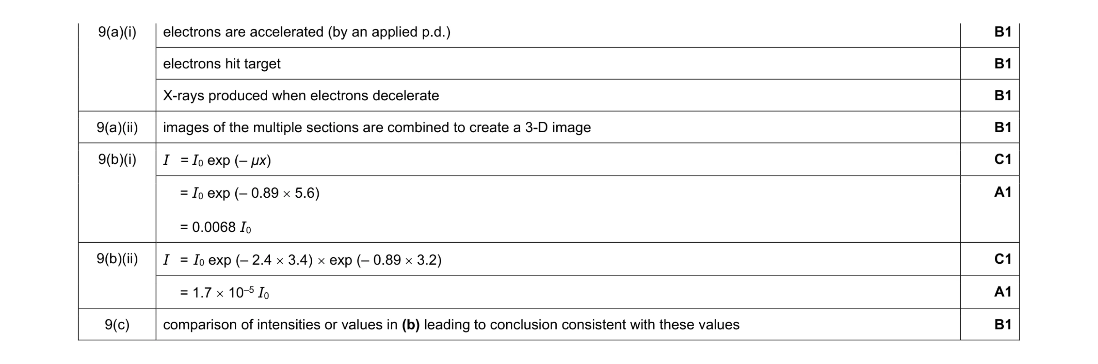 9
9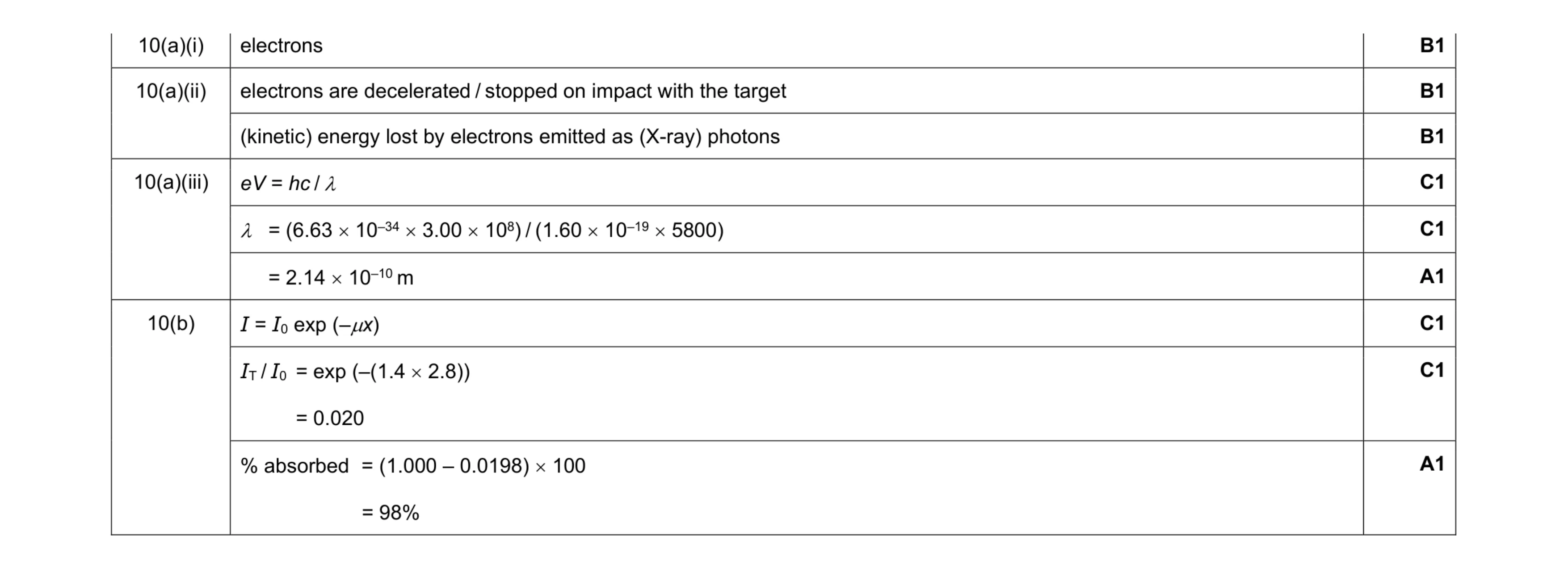 9
9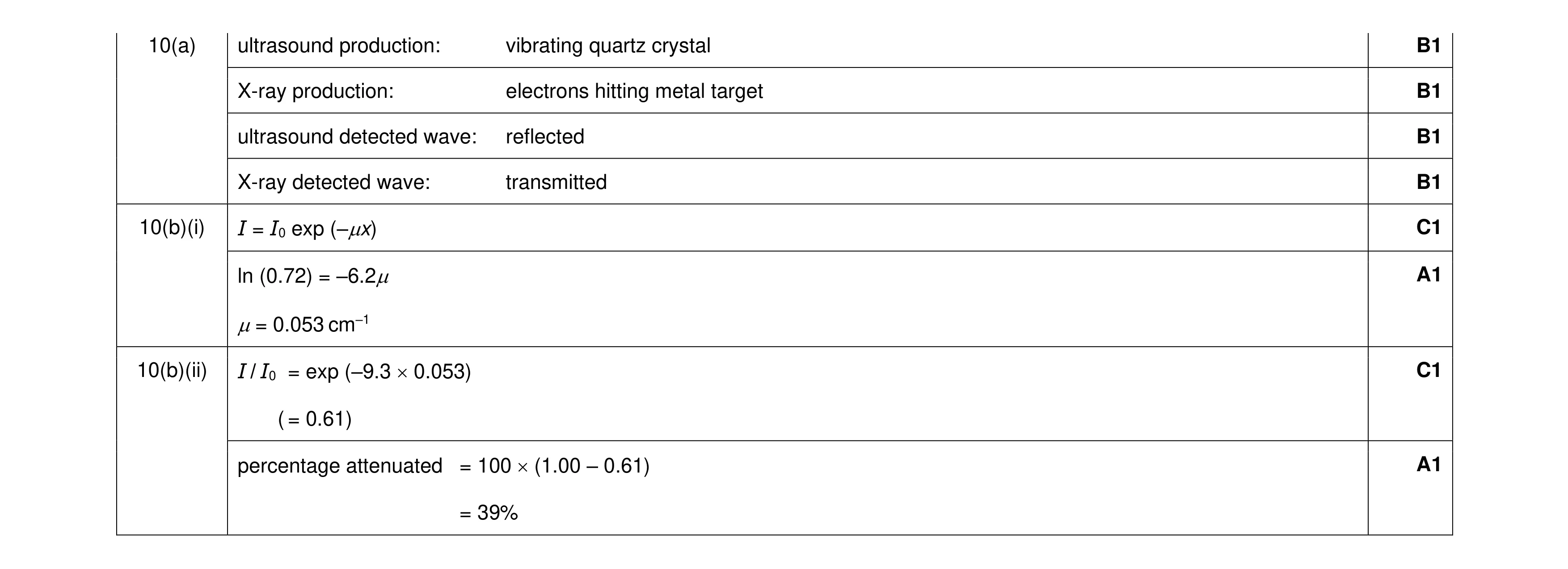 8
8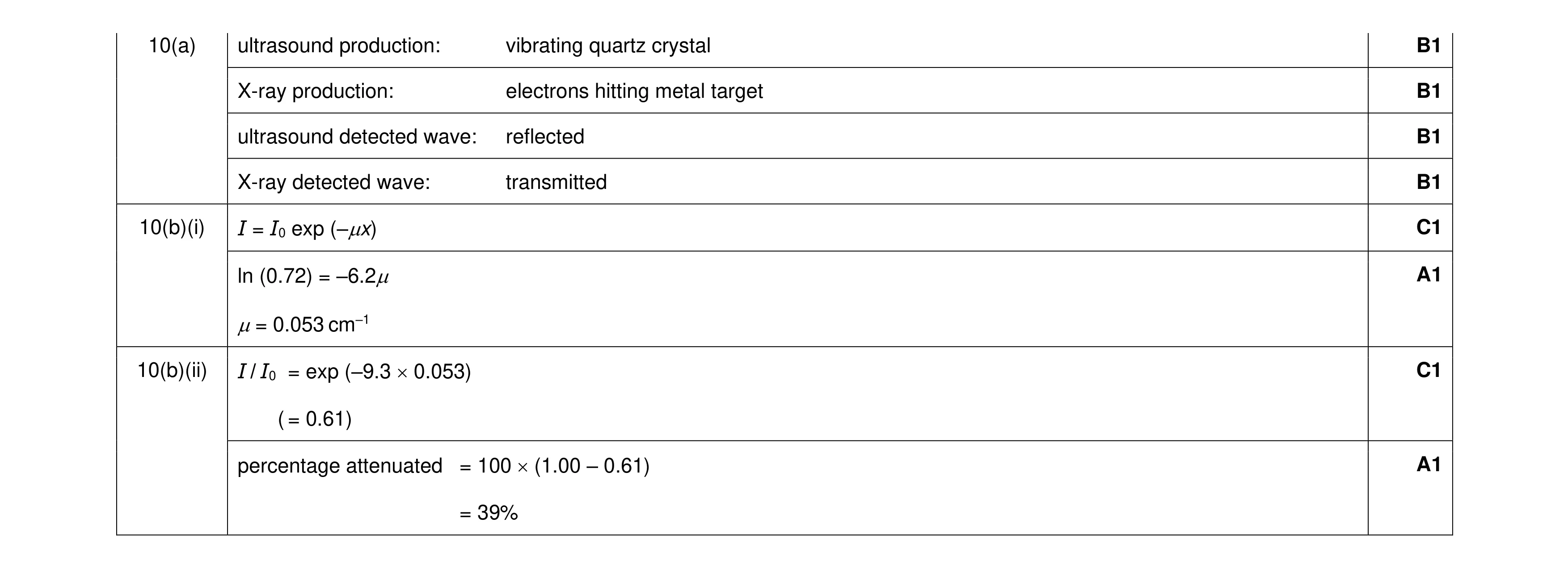 8
8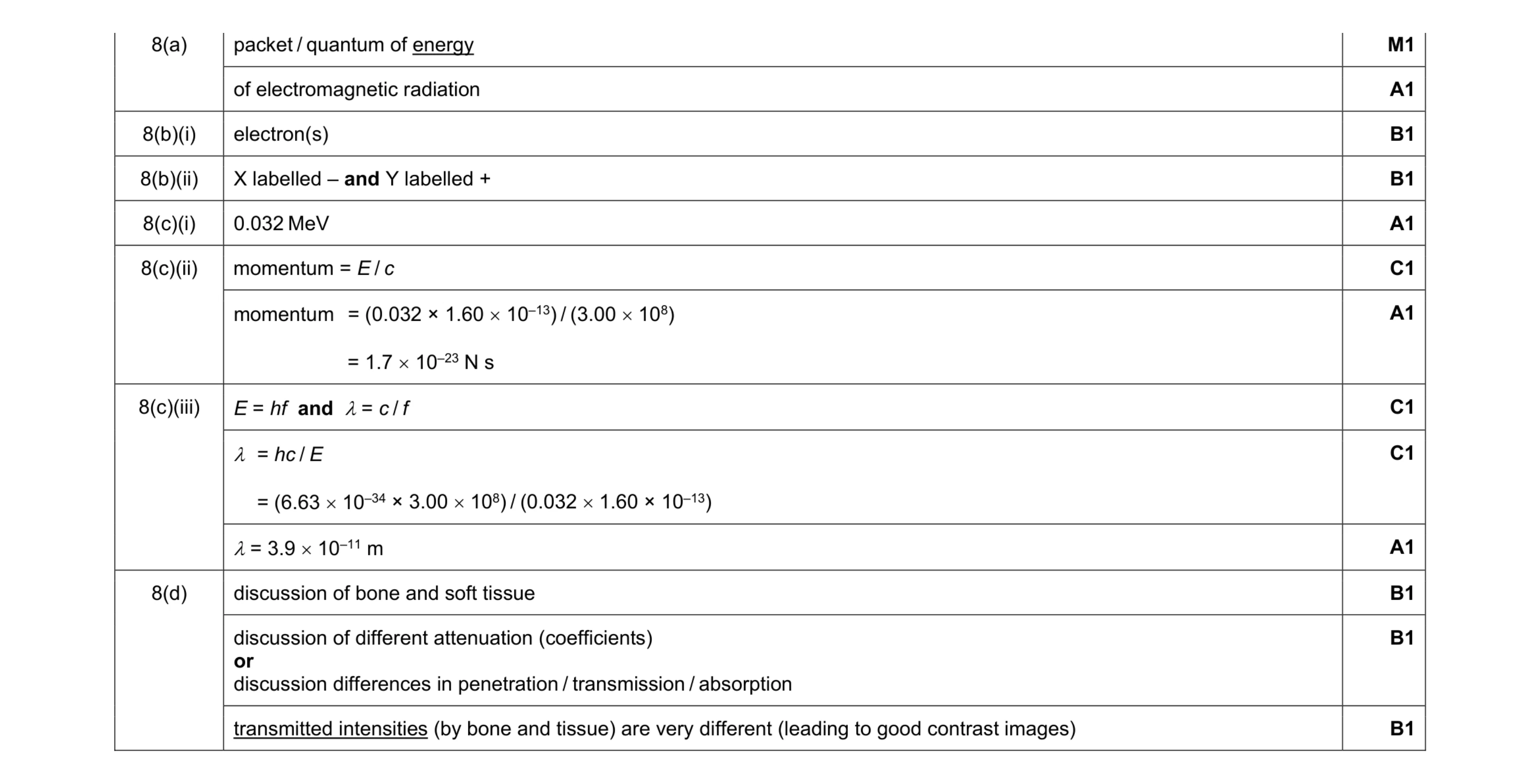 13
13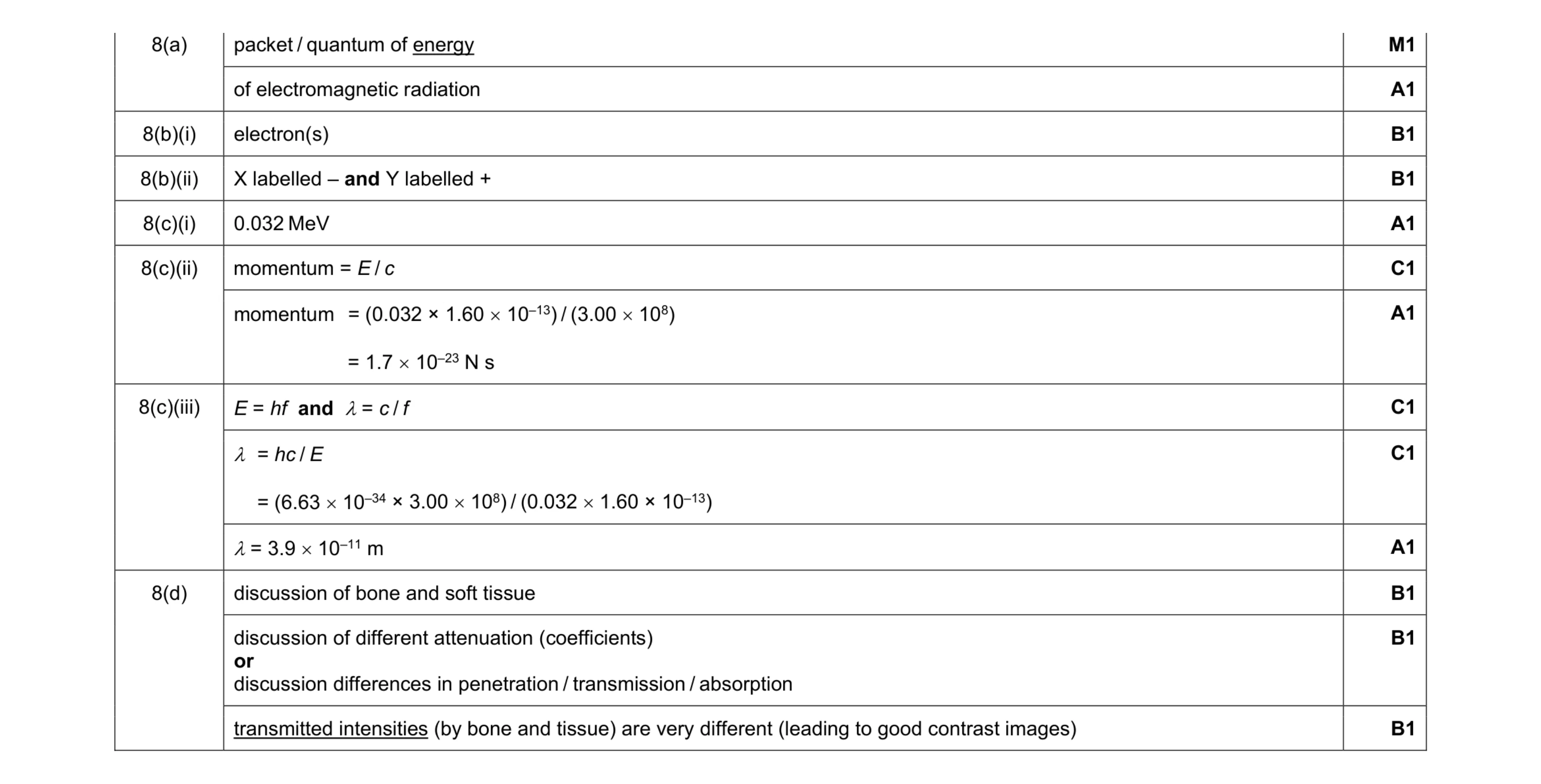 13
13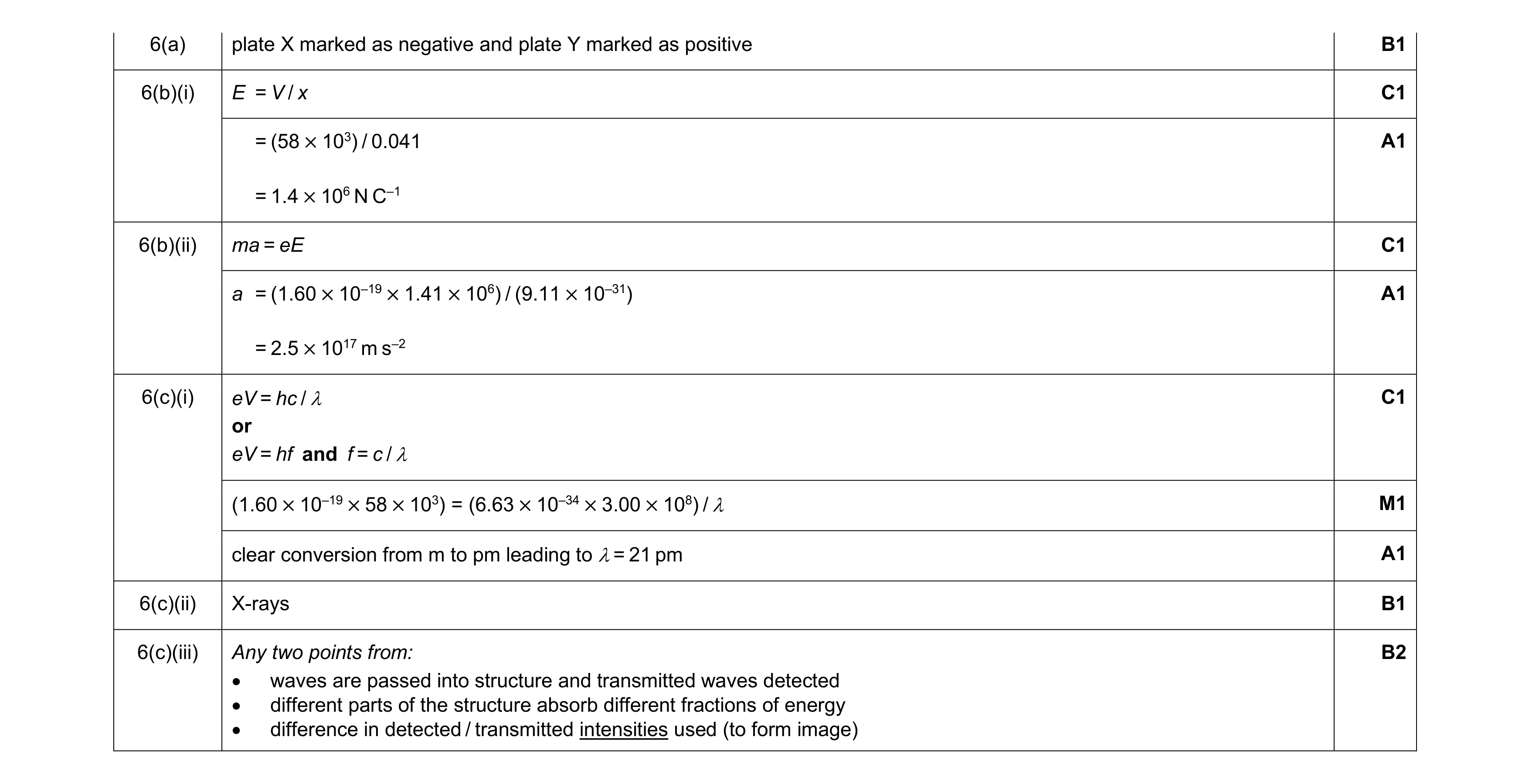 11
11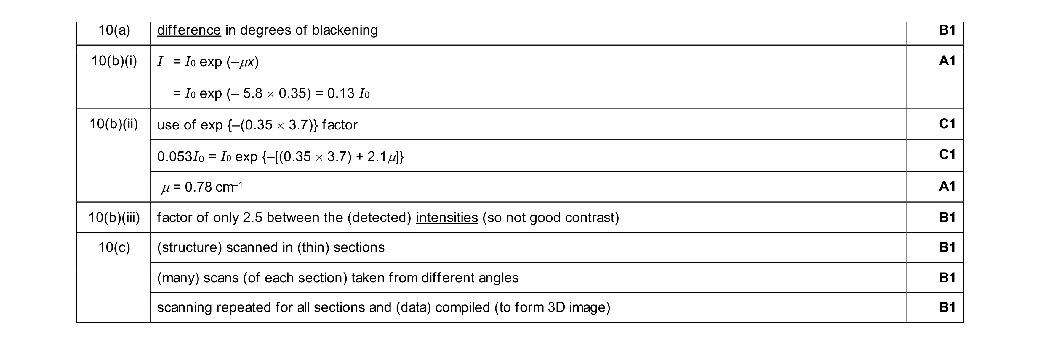 9
9