Questions as text
Question 1 9702/21 Oct/Nov 2017
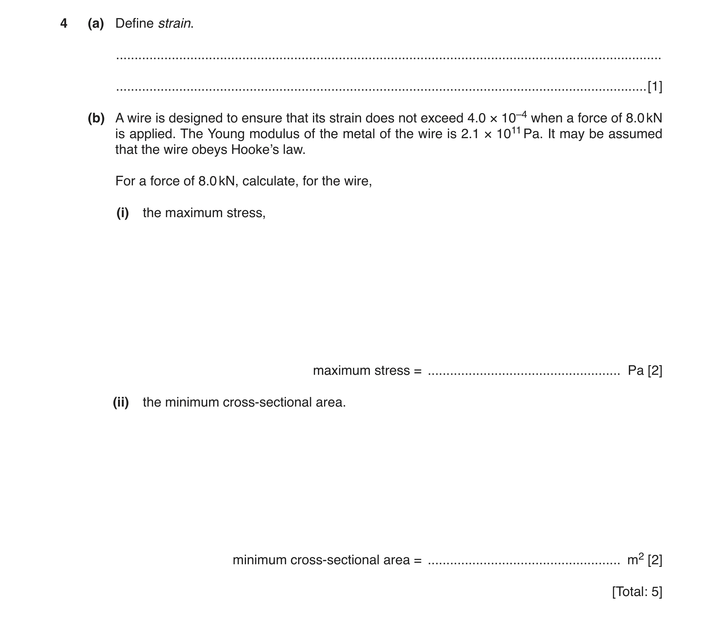
4 (a) Define strain. … … [1] (b) A wire is designed to ensure that its strain does not exceed 4.0 × 10⁻⁴ when a force of 8.0 kN is applied. The Young modulus of the metal of the wire is 2.1 × 10¹¹ Pa. It may be assumed that the wire obeys Hooke’s law. For a force of 8.0 kN, calculate, for the wire, (i) the maximum stress, maximum stress = … Pa [2] (ii) the minimum cross-sectional area. minimum cross-sectional area = … m2 [2] [Total: 5]
5 marks
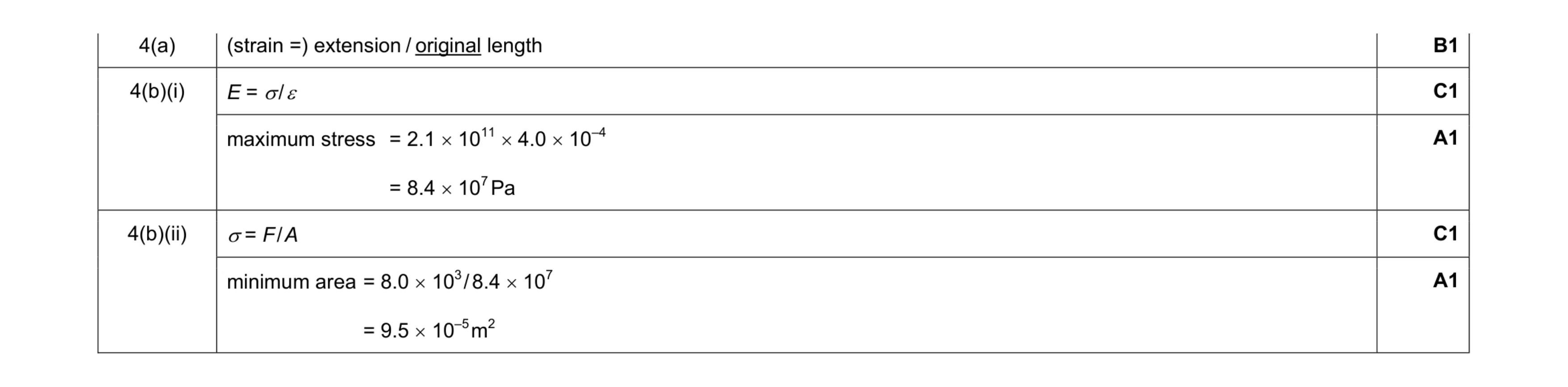
Mark scheme: 4(a) (strain =) extension / original length B1 4(b)(i) E = σ / ε C1 maximum stress = 2.1 × 1011 × 4.0 × 10–4 = 8.4 × 10⁷ Pa A1 4(b)(ii) σ = F / A C1 minimum area = 8.0 × 10³ / 8.4 × 107 = 9.5 × 10⁻⁵ m2 A1
This question in 9702/21 Oct/Nov 2017
Q2 · For the deformation of a wire under tension, define (i) stress, … … [1] (ii) strain 9702/22 Feb/March 2018
3 (a) For the deformation of a wire under tension, define (i) stress, … … [1] (ii) strain. … … [1] (b) A wire is fixed at one end so that it hangs vertically. The wire is given an extension x by suspending a load F from its free end. The variation of F with x is shown in Fig. 3.1. 8 F / N 7 6 5 4 3 2 1 0 0 0.1 0.2 0.3 0.4 0.5 0.6 0.7 0.8 x / mm Fig. 3.1 The wire has cross-sectional area 9.4 × 10⁻⁸ m2 and original length 2.5 m. (i) Describe how measurements can be taken to determine accurately the cross-sectional area of the wire. … … … … … [3] (ii) Determine the Young modulus E of the material of the wire. E = … Pa [2] (iii) Use Fig. 3.1 to calculate the increase in the energy stored in the wire when the load is increased from 2.0 N to 4.0 N. increase in energy = … J [2] (c) The wire in (b) is replaced by a new wire of the same material. The new wire has twice the length and twice the diameter of the old wire. The new wire also obeys Hooke’s law. On Fig. 3.1, sketch the variation with extension x of the load F for the new wire from x = 0 to x = 0.80 mm. [2] [Total: 11]
11 marks
Mark scheme: 3(a)(i) force / (cross-sectional) area B1 3(a)(ii) extension / original length B1 3(b)(i) measure / determine / find diameter B1 using a micrometer / digital calipers B1 several measurements in different places / along the wire / around the circumference (and average them) B1 3(b)(ii) E = σ / ε or E = FL / Ax or E = gradient × (L / A) E = (4 × 2.5) / (0.8 × 10–3) × (9.4 × 10–8) C1 = 1.3 × 10¹¹ Pa A1 Question Answer Marks 3(b)(iii) E = ½Fx or E = ½kx 2 or E = area under graph E = ½ × (2+4) × 0.4 × 10–3 or E = (½ × 4 × 0.8×10–3) – (½ × 2 × 0.4×10–3) or E = [ ½ × 5000 × (0.8×10–3)2 ] – [ ½ × 5000 × (0.4×10–3)2 ] C1 E = 1.2 × 10⁻³ J A1 3(c) straight line from the origin and above the original line M1 straight line passes through (0.80, 8.0) A1
This question in 9702/22 Feb/March 2018
Q3 · Define the Young modulus of a material 9702/23 May/June 2018
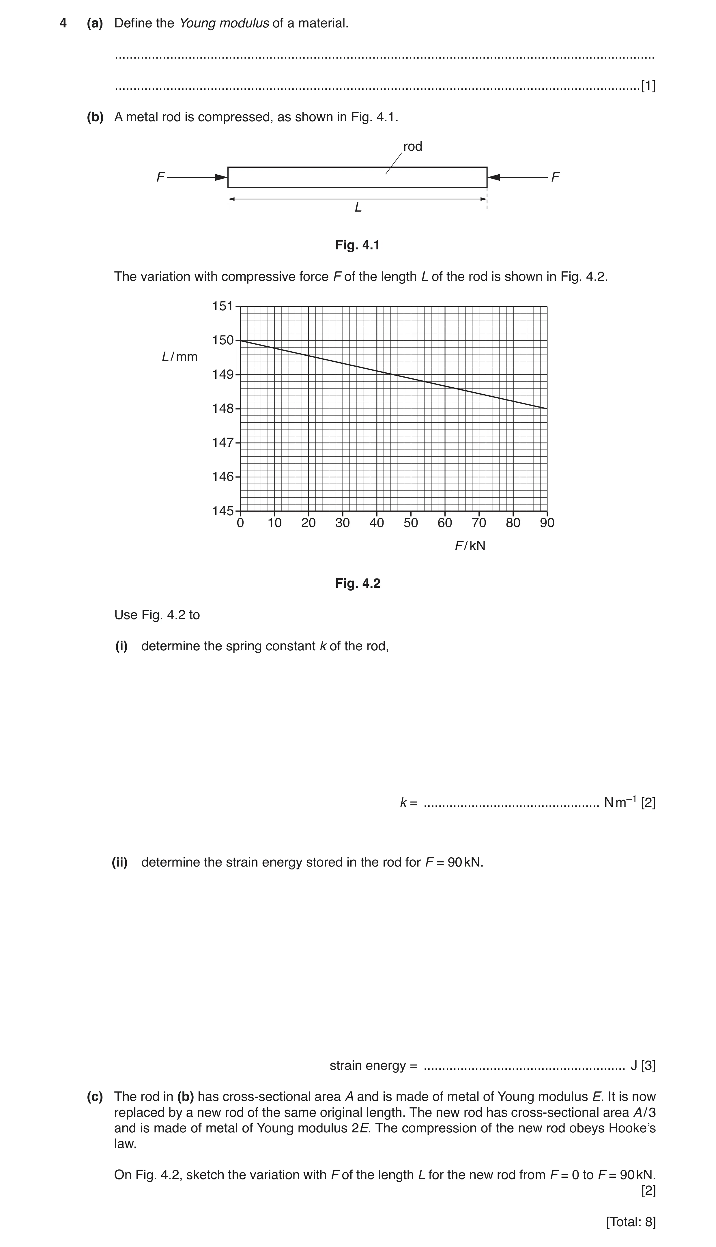
4 (a) Define the Young modulus of a material. … … [1] (b) A metal rod is compressed, as shown in Fig. 4.1. rod F F L Fig. 4.1 The variation with compressive force F of the length L of the rod is shown in Fig. 4.2. 151 150 L / mm 149 148 147 146 145 0 10 20 30 40 50 60 70 80 90 F / kN Fig. 4.2 Use Fig. 4.2 to (i) determine the spring constant k of the rod, k = … N m–1 [2] (ii) determine the strain energy stored in the rod for F = 90 kN. strain energy = … J [3] (c) The rod in (b) has cross-sectional area A and is made of metal of Young modulus E. It is now replaced by a new rod of the same original length. The new rod has cross-sectional area A / 3 and is made of metal of Young modulus 2E. The compression of the new rod obeys Hooke’s law. On Fig. 4.2, sketch the variation with F of the length L for the new rod from F = 0 to F = 90 kN. [2] [Total: 8]
8 marks
Mark scheme: 4(a) (Young modulus =) stress / strain B1 4(b)(i) k = F / ∆L or 1 / gradient C1 = 90 × 103 / (2 × 10⁻³) (or other point on line) = 4.5 × 10⁷ N m–1 A1 4(b)(ii) E = ½F∆L or E = ½k(∆L)2 C1 = ½ × 90 × 103 × 2 × 10–3 or ½ × 4.5 × 107 × (2 × 10–3)2 C1 = 90 J A1 4(c) straight line starting from (0, 150) and below original line M1 line ends at (90, 147) A1
This question in 9702/23 May/June 2018
Q4 · State Newton’s second law of motion 9702/22 May/June 2019
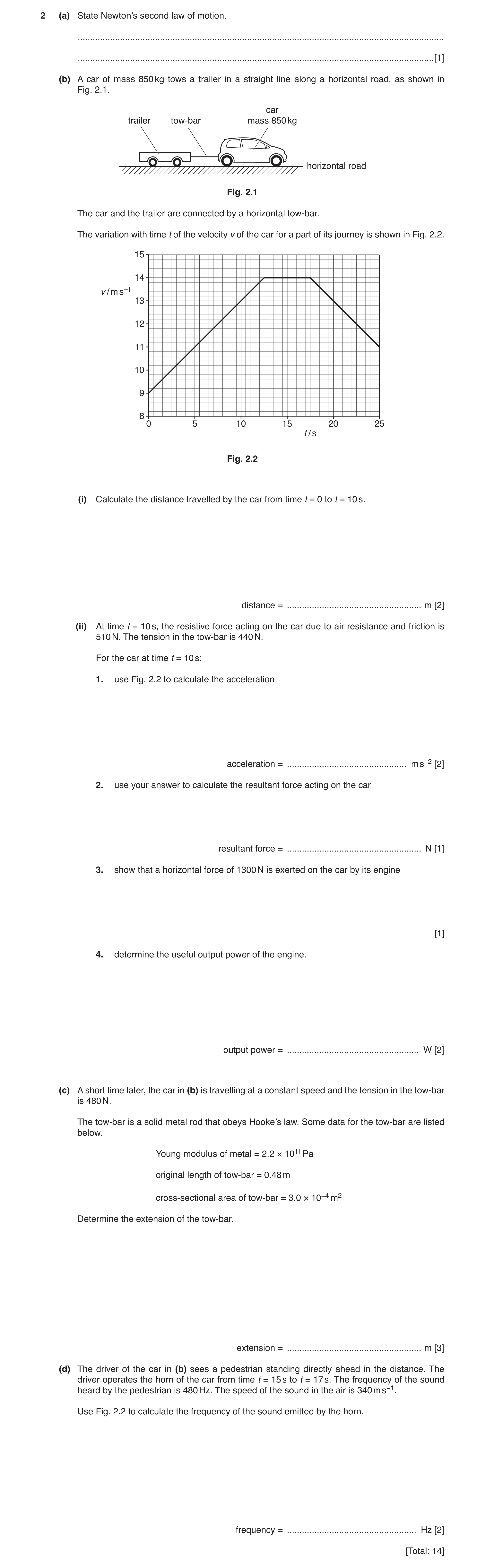
2 (a) State Newton’s second law of motion. … … [1] (b) A car of mass 850 kg tows a trailer in a straight line along a horizontal road, as shown in Fig. 2.1. car trailer tow-bar mass 850 kg horizontal road Fig. 2.1 The car and the trailer are connected by a horizontal tow-bar. The variation with time t of the velocity v of the car for a part of its journey is shown in Fig. 2.2. 15 14 v / m s–1 13 12 11 10 9 8 0 5 10 15 20 25 t / s Fig. 2.2 (i) Calculate the distance travelled by the car from time t = 0 to t = 10 s. distance = … m [2] (ii) At time t = 10 s, the resistive force acting on the car due to air resistance and friction is 510 N. The tension in the tow-bar is 440 N. For the car at time t = 10 s: 1. use Fig. 2.2 to calculate the acceleration acceleration = … m s−2 [2] 2. use your answer to calculate the resultant force acting on the car resultant force = … N [1] 3. show that a horizontal force of 1300 N is exerted on the car by its engine [1] 4. determine the useful output power of the engine. output power = … W [2] (c) A short time later, the car in (b) is travelling at a constant speed and the tension in the tow-bar is 480 N. The tow-bar is a solid metal rod that obeys Hooke’s law. Some data for the tow-bar are listed below. Young modulus of metal = 2.2 × 10¹¹ Pa original length of tow-bar = 0.48 m cross-sectional area of tow-bar = 3.0 × 10⁻⁴ m2 Determine the extension of the tow-bar. extension = … m [3] (d) The driver of the car in (b) sees a pedestrian standing directly ahead in the distance. The driver operates the horn of the car from time t = 15 s to t = 17 s. The frequency of the sound heard by the pedestrian is 480 Hz. The speed of the sound in the air is 340 m s−1. Use Fig. 2.2 to calculate the frequency of the sound emitted by the horn. frequency = … Hz [2] [Total: 14]
14 marks
Mark scheme: 2(a) (resultant) force proportional/equal to/is rate of change of momentum B1 2(b)(i) distance = area under graph or s = ½ (u + v) t = ½ × (9 + 13) × 10 or s = ut + ½at 2 = (9 × 10) + (½ × 0.40 × 10²) or s = vt – ½at 2 = (13 × 10) – (½ × 0.40 × 10²) or v 2 = u 2 + 2as 132 = 92 + (2 × 0.40 × s) C1 distance = 110 m A1 Question Answer Marks 2(b)(ii) 1. a = gradient or a = (v – u) / t or a = ∆v / (∆)t e.g. a = (14 – 9) / 12.5 or (13 – 9) / 10 C1 a = 0.40 m s–2 A1 2. resultant force = 850 × 0.40 = 340 N A1 3. (F =) 510 + 440 + 340 = 1300 (N) A1 4. P = Fv C1 = 1300 × 13 = 1.7 × 10⁴ W A1 2(c) E = σ / ε C1 E = (F / A) / (∆L / L) or E = FL / A∆L C1 ∆L = (480 × 0.48) / (3.0 × 10–4 × 2.2 × 1011) = 3.5 × 10⁻⁶ m A1 2(d) fo = fs v / (v – vs) 480 = fs × 340 / (340 – 14) C1 fs = 460 Hz A1
This question in 9702/22 May/June 2019
Q5 · State two conditions for an object to be in equilibrium 9702/21 May/June 2020
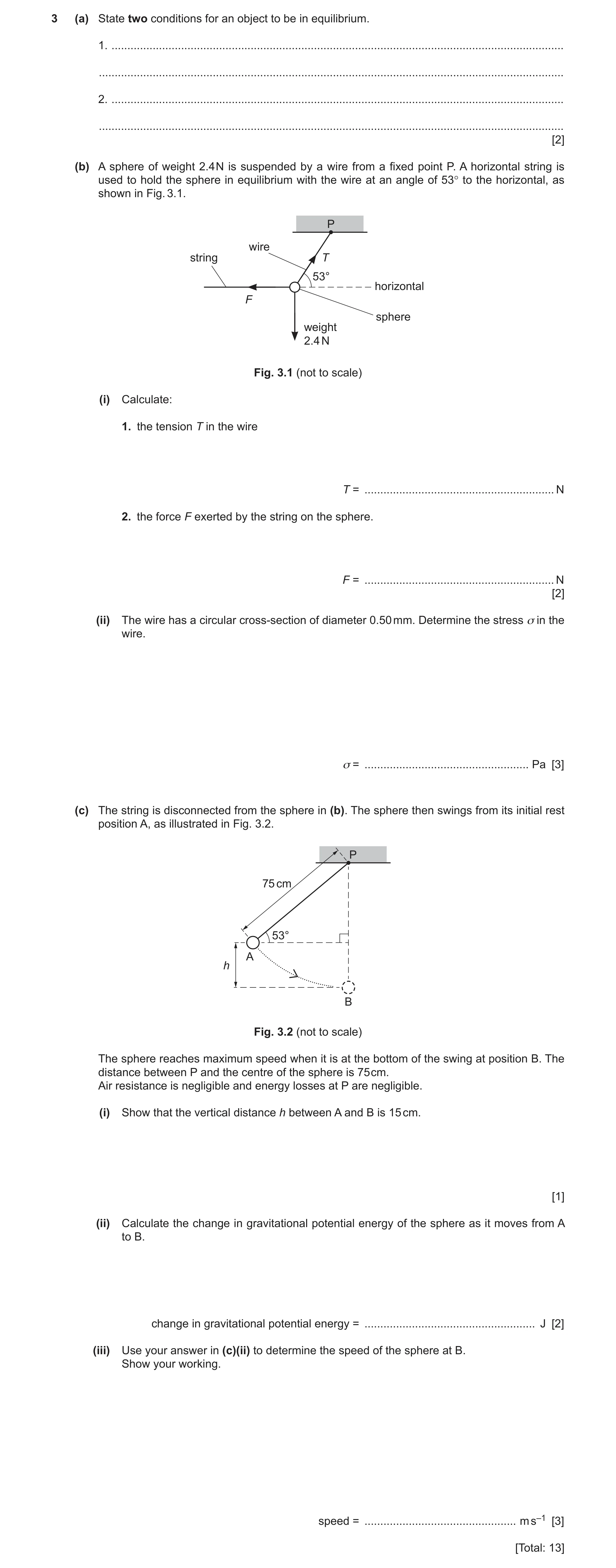
3 (a) State two conditions for an object to be in equilibrium. 1. … … 2. … … [2] (b) A sphere of weight 2.4 N is suspended by a wire from a fixed point P. A horizontal string is used to hold the sphere in equilibrium with the wire at an angle of 53° to the horizontal, as shown in Fig. 3.1. P wire string T 53° horizontal F sphere weight 2.4 N Fig. 3.1 (not to scale) (i) Calculate: 1. the tension T in the wire T = … N 2. the force F exerted by the string on the sphere. F = … N [2] (ii) The wire has a circular cross-section of diameter 0.50 mm. Determine the stress σ in the wire. σ = … Pa [3] (c) The string is disconnected from the sphere in (b). The sphere then swings from its initial rest position A, as illustrated in Fig. 3.2. P 75 cm 53° A h B Fig. 3.2 (not to scale) The sphere reaches maximum speed when it is at the bottom of the swing at position B. The distance between P and the centre of the sphere is 75 cm. Air resistance is negligible and energy losses at P are negligible. (i) Show that the vertical distance h between A and B is 15 cm. [1] (ii) Calculate the change in gravitational potential energy of the sphere as it moves from A to B. change in gravitational potential energy = … J [2] (iii) Use your answer in (c)(ii) to determine the speed of the sphere at B. Show your working. speed = … m s–1 [3] [Total: 13]
13 marks
Mark scheme: 3(a) resultant force (in any direction) is zero B1 resultant torque/moment (about any point) is zero B1 3(b)(i) 1. T sin 53° = 2.4 T = 3.0 N A1 2. F = T cos 53° or F 2 = T 2 – 2.42 F = 1.8 N A1 3(b)(ii) σ = T / A or σ = F / A C1 A = πd2 / 4 or A = πr2 C1 σ = 3.0 × 4 / [π × (0.50 × 10⁻³)2] = 1.5 × 10⁷ Pa A1 3(c)(i) h = 75 – 75 sin 53° = 15 cm A1 3(c)(ii) (Δ)E = mg(Δ)h or (Δ)E = W(Δ)h C1 (Δ)E = 2.4 × 15 × 10–2 = 0.36 J A1 3(c)(iii) E = ½mv2 B1 0.36 = ½ × (2.4 / 9.81) × v2 C1 v = 1.7 m s–1 A1
This question in 9702/21 May/June 2020
Q6 · Define, for a wire: (i) stress … … [1] (ii) strain 9702/21 Oct/Nov 2020
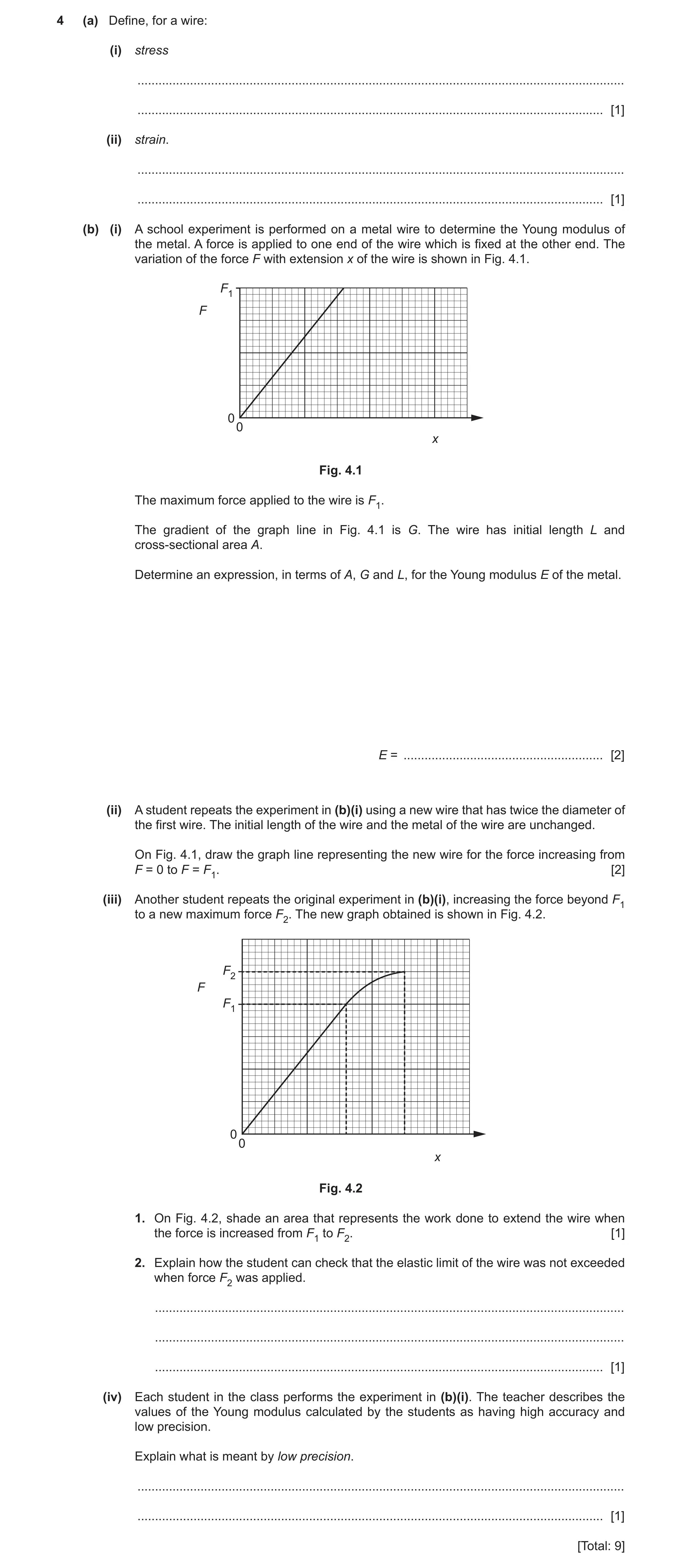
4 (a) Define, for a wire: (i) stress … … [1] (ii) strain. … … [1] (b) (i) A school experiment is performed on a metal wire to determine the Young modulus of the metal. A force is applied to one end of the wire which is fixed at the other end. The variation of the force F with extension x of the wire is shown in Fig. 4.1. F1 F 00 x Fig. 4.1 The maximum force applied to the wire is F1. The gradient of the graph line in Fig. 4.1 is G. The wire has initial length L and cross-sectional area A. Determine an expression, in terms of A, G and L, for the Young modulus E of the metal. E = … [2] (ii) A student repeats the experiment in (b)(i) using a new wire that has twice the diameter of the first wire. The initial length of the wire and the metal of the wire are unchanged. On Fig. 4.1, draw the graph line representing the new wire for the force increasing from F = 0 to F = F1. [2] (iii) Another student repeats the original experiment in (b)(i), increasing the force beyond F1 to a new maximum force F2. The new graph obtained is shown in Fig. 4.2. F2 F F1 00 x Fig. 4.2 1. On Fig. 4.2, shade an area that represents the work done to extend the wire when the force is increased from F1 to F2. [1] 2. Explain how the student can check that the elastic limit of the wire was not exceeded when force F 2 was applied. … … … [1] (iv) Each student in the class performs the experiment in (b)(i). The teacher describes the values of the Young modulus calculated by the students as having high accuracy and low precision. Explain what is meant by low precision. … … [1] [Total: 9]
9 marks
Mark scheme: 4(a)(i) (stress =) force / cross-sectional area B1 4(a)(ii) (strain =) extension / original length B1 4(b)(i) E = FL / Ax C1 = GL / A A1 4(b)(ii) straight line from origin above the original line M1 line ends at point (4 small squares, F1). A1 4(b)(iii) 1. shaded area below the graph line and between the two vertical dashed lines B1 2. remove the force/F/F2 and the wire goes back to original length/zero extension B1 4(b)(iv) values have a large range B1
This question in 9702/21 Oct/Nov 2020
Q7 · A uniform metal bar, initially unstretched, has sides of length w, x and y, as shown in… 9702/21 Oct/Nov 2021
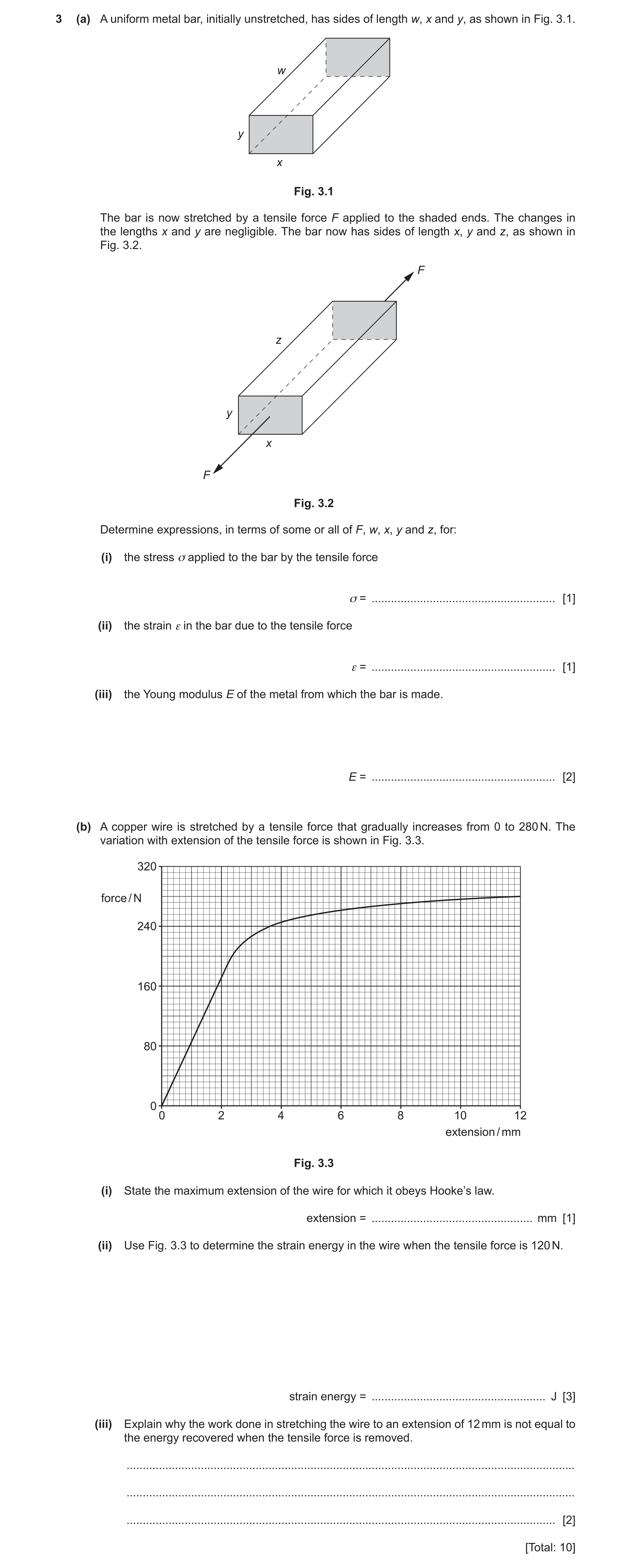
3 (a) A uniform metal bar, initially unstretched, has sides of length w, x and y, as shown in Fig. 3.1. w y x Fig. 3.1 The bar is now stretched by a tensile force F applied to the shaded ends. The changes in the lengths x and y are negligible. The bar now has sides of length x, y and z, as shown in Fig. 3.2. F z y x F Fig. 3.2 Determine expressions, in terms of some or all of F, w, x, y and z, for: (i) the stress σ applied to the bar by the tensile force σ = … [1] (ii) the strain ε in the bar due to the tensile force ε = … [1] (iii) the Young modulus E of the metal from which the bar is made. E = … [2] (b) A copper wire is stretched by a tensile force that gradually increases from 0 to 280 N. The variation with extension of the tensile force is shown in Fig. 3.3. 320 force / N 240 160 80 0 0 2 4 6 8 10 12 extension / mm Fig. 3.3 (i) State the maximum extension of the wire for which it obeys Hooke’s law. extension = … mm [1] (ii) Use Fig. 3.3 to determine the strain energy in the wire when the tensile force is 120 N. strain energy = … J [3] (iii) Explain why the work done in stretching the wire to an extension of 12 mm is not equal to the energy recovered when the tensile force is removed. … … … [2] [Total: 10]
10 marks
Mark scheme: 3(a)(i) σ = F / xy B1 3(a)(ii) ε = (z – w) / w B1 3(a)(iii) E = σ / ε C1 = Fw / xy(z – w) A1 3(b)(i) extension = 2.2 mm (allow 2.0–2.4 mm) A1 3(b)(ii) strain energy = area under graph/line or ½Fx or ½kx2 C1 = ½ × 120 × 1.4 × 10–3 or ½ × 8.6 × 104 × (1.4 × 10–3)2 C1 = 0.084 J A1 3(b)(iii) (some of the) deformation of the wire is plastic/permanent/not elastic or wire goes past the elastic limit/enters plastic region B1 energy (that cannot be recovered) is dissipated as thermal energy/becomes internal energy B1
This question in 9702/21 Oct/Nov 2021
Q8 · A motor uses a wire to raise a block, as illustrated in Fig 9702/22 Feb/March 2023
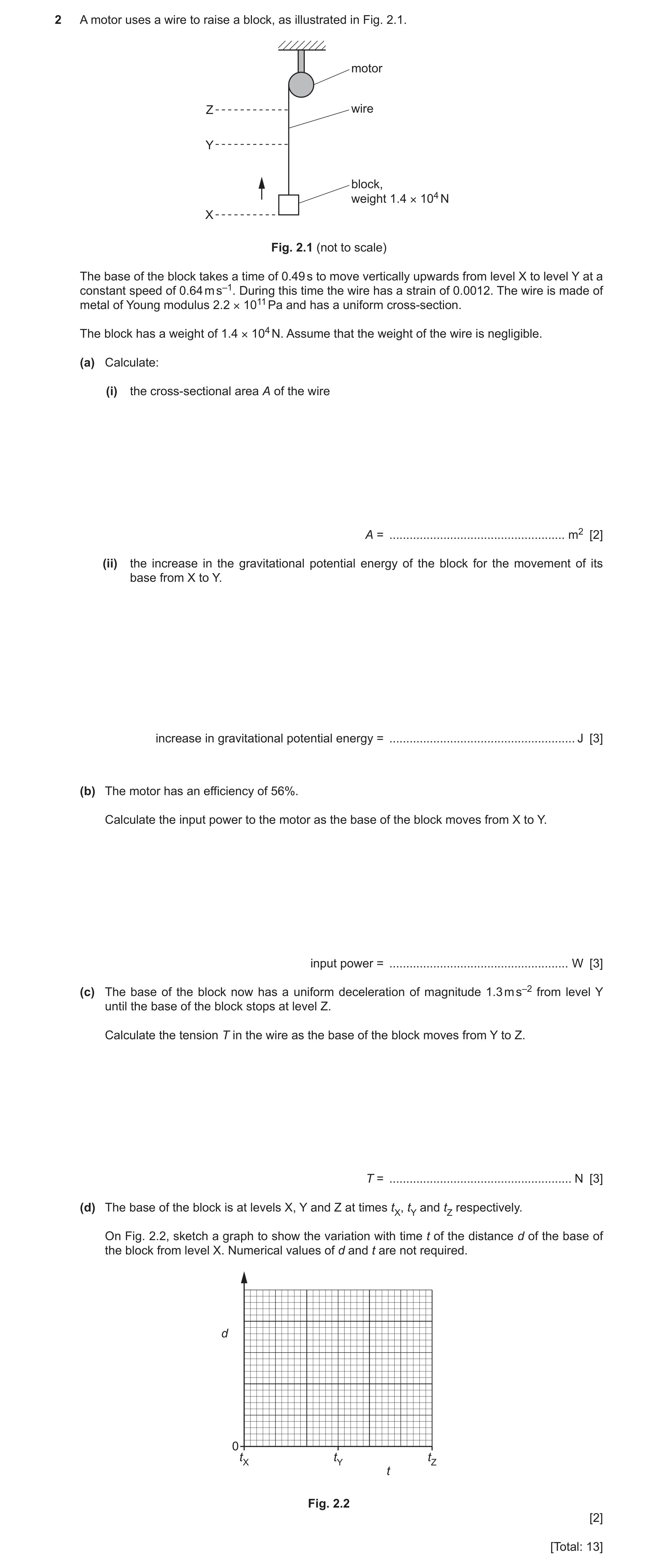
2 A motor uses a wire to raise a block, as illustrated in Fig. 2.1. motor Z wire Y block, weight 1.4 × 10⁴ N X Fig. 2.1 (not to scale) The base of the block takes a time of 0.49 s to move vertically upwards from level X to level Y at a constant speed of 0.64 m s–1. During this time the wire has a strain of 0.0012. The wire is made of metal of Young modulus 2.2 × 10¹¹ Pa and has a uniform cross-section. The block has a weight of 1.4 × 10⁴ N. Assume that the weight of the wire is negligible. (a) Calculate: (i) the cross-sectional area A of the wire A = … m2 [2] (ii) the increase in the gravitational potential energy of the block for the movement of its base from X to Y. increase in gravitational potential energy = … J [3] (b) The motor has an efficiency of 56%. Calculate the input power to the motor as the base of the block moves from X to Y. input power = … W [3] (c) The base of the block now has a uniform deceleration of magnitude 1.3 m s–2 from level Y until the base of the block stops at level Z. Calculate the tension T in the wire as the base of the block moves from Y to Z. T = … N [3] (d) The base of the block is at levels X, Y and Z at times tX, tY and tZ respectively. On Fig. 2.2, sketch a graph to show the variation with time t of the distance d of the base of the block from level X. Numerical values of d and t are not required. d 0 tX tY tZ t Fig. 2.2 [2] [Total: 13]
13 marks
Mark scheme: 2(a)(i) E = / or E = F / A C1 A = 1.4 104 / (2.2 1011 0.0012) A1 = 5.3 10–5 m2 2(a)(ii) (∆)h = 0.64 0.49 (= 0.3136) C1 (∆)E = mg(∆)h or W(∆)h C1 = 1.4 104 0.64 0.49 A1 = 4.4 103 J 2(b) P = Fv or W / t C1 = (1.4 104 0.64) / 0.56 or (4.4 103 / 0.49) / 0.56 C1 = 1.6 104 W A1 2(c) m = 1.4 104 / 9.81 C1 ( = 1427 kg) (resultant) F = (1.4 104 / 9.81) 1.3 C1 ( = 1855 N) T = 1.4 104 – 1855 or (1.4104 / 9.81) (9.81 – 1.3) A1 = 1.2 104 N 2(d) upward sloping straight line from (tX, 0) to tY B1 from tY to tZ: an upward sloping curve with decreasing magnitude of gradient (that is horizontal at tZ) B1
This question in 9702/22 Feb/March 2023
Q9 · Define the Young modulus 9702/23 May/June 2023
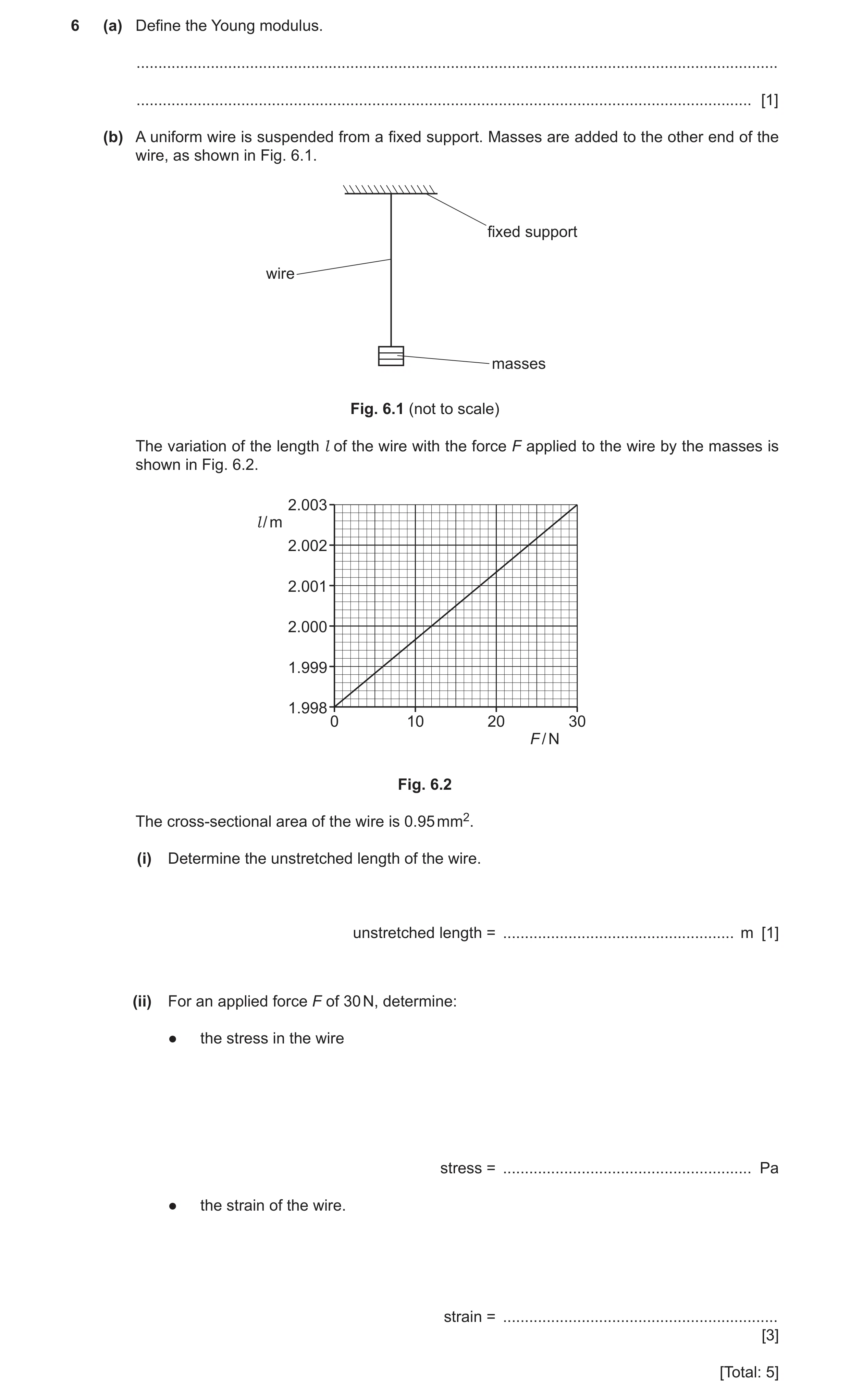
6 (a) Define the Young modulus. … … [1] (b) A uniform wire is suspended from a fixed support. Masses are added to the other end of the wire, as shown in Fig. 6.1. fixed support wire masses Fig. 6.1 (not to scale) The variation of the length l of the wire with the force F applied to the wire by the masses is shown in Fig. 6.2. 2.003 l / m 2.002 2.001 2.000 1.999 1.998 0 10 20 30 F / N Fig. 6.2 The cross-sectional area of the wire is 0.95 mm2. (i) Determine the unstretched length of the wire. unstretched length = … m [1] (ii) For an applied force F of 30 N, determine: ● the stress in the wire stress = … Pa ● the strain of the wire. strain = … [3] [Total: 5]
5 marks
Mark scheme: 6(a) (Young modulus =) stress / strain B1 6(b)(i) unstretched length = 1.9980 m A1 6(b)(ii) stress = F / A C1 = 30 / 9.5 10–7 = 3.2 107 Pa A1 strain = 0.0050 / 1.9980 = 2.5 10–3 A1
This question in 9702/23 May/June 2023
Q10 · A hot-air balloon floats just above the ground 9702/21 Oct/Nov 2023
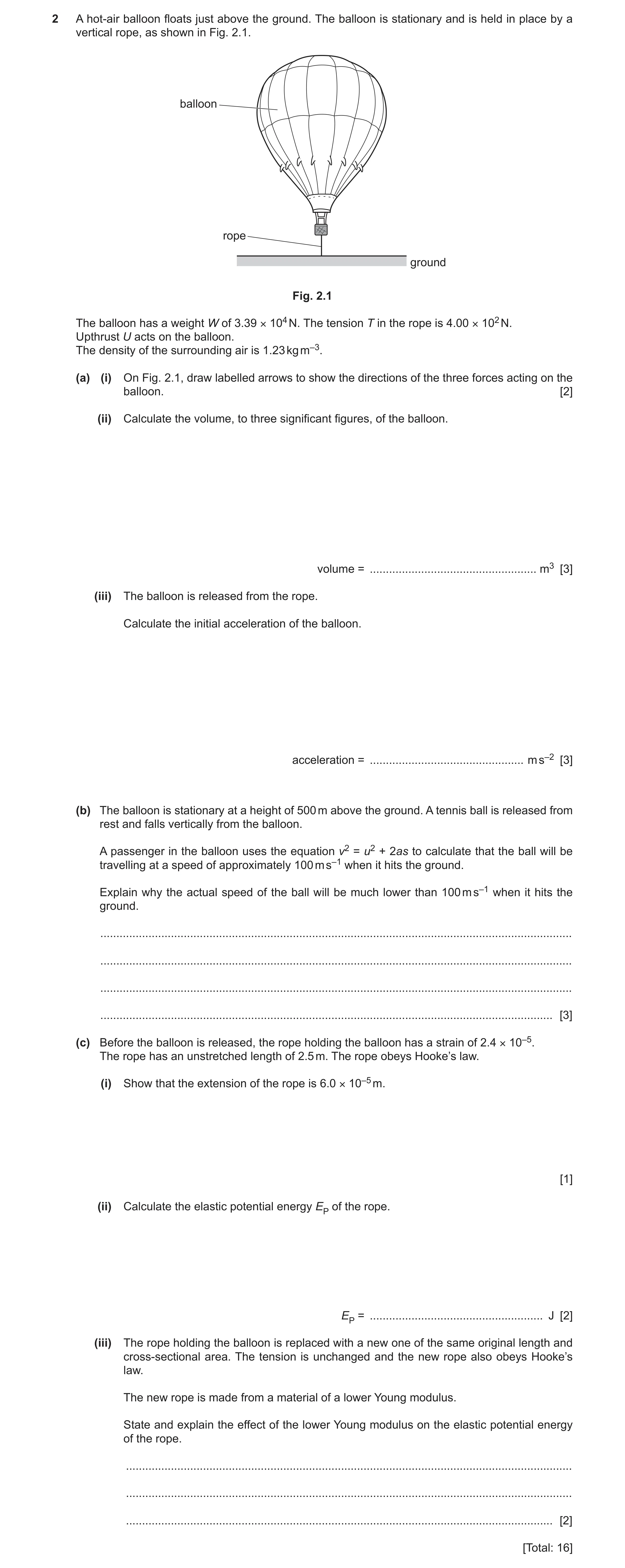
2 A hot-air balloon floats just above the ground. The balloon is stationary and is held in place by a vertical rope, as shown in Fig. 2.1. balloon rope ground Fig. 2.1 The balloon has a weight W of 3.39 × 10⁴ N. The tension T in the rope is 4.00 × 10² N. Upthrust U acts on the balloon. The density of the surrounding air is 1.23 kg m–3. (a) (i) On Fig. 2.1, draw labelled arrows to show the directions of the three forces acting on the balloon. [2] (ii) Calculate the volume, to three significant figures, of the balloon. volume = … m3 [3] (iii) The balloon is released from the rope. Calculate the initial acceleration of the balloon. acceleration = … m s–2 [3] (b) The balloon is stationary at a height of 500 m above the ground. A tennis ball is released from rest and falls vertically from the balloon. A passenger in the balloon uses the equation v2 = u2 + 2as to calculate that the ball will be travelling at a speed of approximately 100 m s–1 when it hits the ground. Explain why the actual speed of the ball will be much lower than 100 m s–1 when it hits the ground. … … … … [3] (c) Before the balloon is released, the rope holding the balloon has a strain of 2.4 × 10⁻⁵. The rope has an unstretched length of 2.5 m. The rope obeys Hooke’s law. (i) Show that the extension of the rope is 6.0 × 10⁻⁵ m. [1] (ii) Calculate the elastic potential energy EP of the rope. EP = … J [2] (iii) The rope holding the balloon is replaced with a new one of the same original length and cross-sectional area. The tension is unchanged and the new rope also obeys Hooke’s law. The new rope is made from a material of a lower Young modulus. State and explain the effect of the lower Young modulus on the elastic potential energy of the rope. … … … [2] [Total: 16]
16 marks
Mark scheme: 2(a)(i) arrow upwards () and labelled upthrust / U B2 arrow downwards () and labelled weight / W / mg arrow downwards () and labelled tension / T 1 mark: One or two correctly labelled arrows 2 marks: Three correctly labelled arrows 2(a)(ii) U = T + W or upthrust = tension + weight C1 Vg = T + W C1 V = [(4.00 102) + (3.39 104)] / (1.23 9.81) V = 2.84 103 m3 A1 2(a)(iii) m = W / g or a = F / m C1 a = (4.00 102) / [(3.39 104) / 9.81)] C1 a = 0.12 m s–2 A1 2(b) there is air resistance (which increases with speed) B1 (average) resultant force is less (than weight) B1 (average) acceleration is less (than g / 9.81, so speed is less than 100 m s–1) B1 2(c)(i) (extension =) 2.5 2.4 10–5 = 6.0 10–5 (m) A1 2(c)(ii) E(P) = ½ Fx C1 or E(P) = ½ kx2 and F = kx E(P) = ½ 4.00 102 6.0 10–5 or E(P) = ½ 6.7 106 (6.0 10–5)2 A1 E(P) = 0.012 J 2(c)(iii) longer extension M1 or smaller spring constant elastic potential energy is greater A1
This question in 9702/21 Oct/Nov 2023
Q11 · A thin metal wire X, of diameter 1.2 × 10⁻³ m, is used to suspend a model planet, as… 9702/22 Feb/March 2024
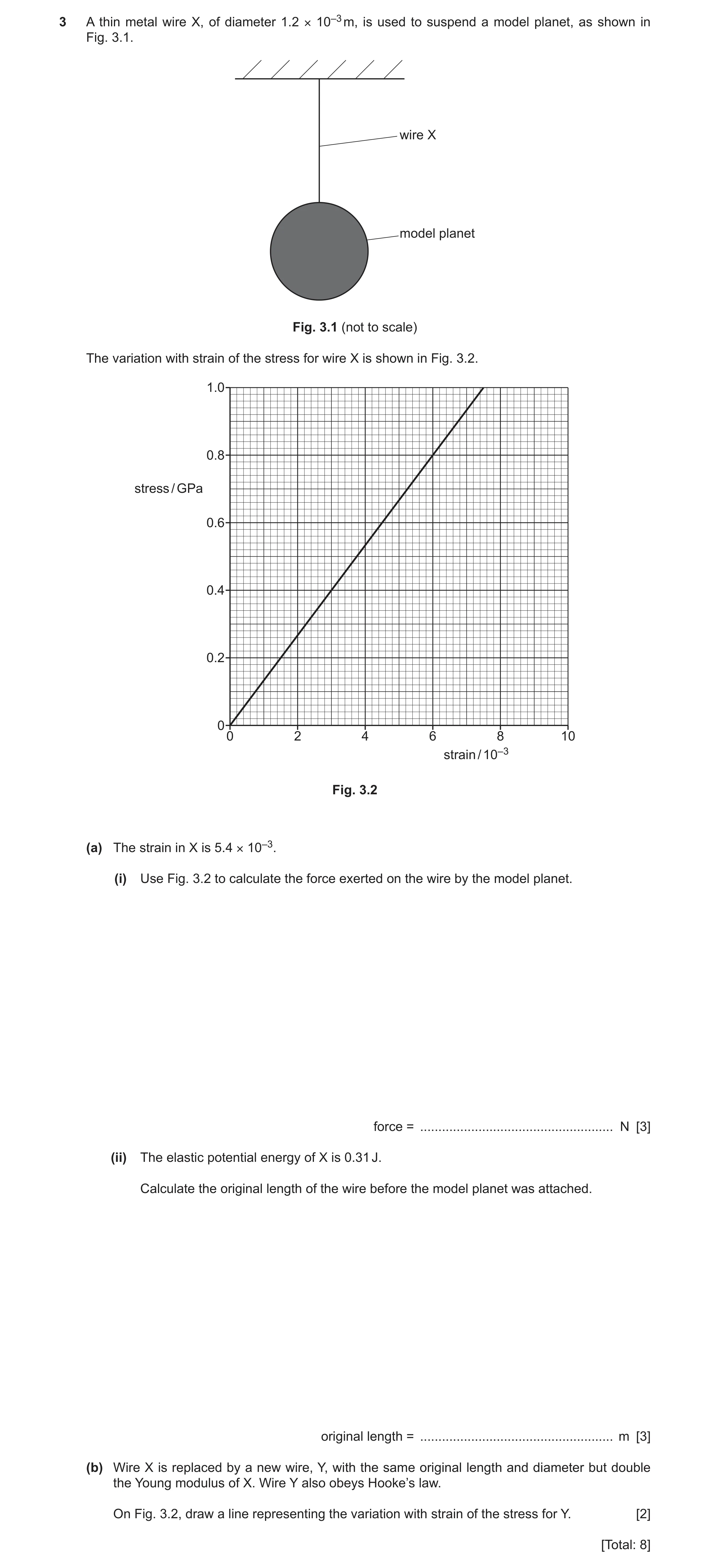
3 A thin metal wire X, of diameter 1.2 × 10⁻³ m, is used to suspend a model planet, as shown in Fig. 3.1. wire X model planet Fig. 3.1 (not to scale) The variation with strain of the stress for wire X is shown in Fig. 3.2. 1.0 0.8 stress / GPa 0.6 0.4 0.2 0 0 2 4 6 8 10 strain / 10–3 Fig. 3.2 (a) The strain in X is 5.4 × 10⁻³. (i) Use Fig. 3.2 to calculate the force exerted on the wire by the model planet. force = … N [3] (ii) The elastic potential energy of X is 0.31 J. Calculate the original length of the wire before the model planet was attached. original length = … m [3] (b) Wire X is replaced by a new wire, Y, with the same original length and diameter but double the Young modulus of X. Wire Y also obeys Hooke’s law. On Fig. 3.2, draw a line representing the variation with strain of the stress for Y. [2] [Total: 8]
8 marks
Mark scheme: 3(a)(i) = 0.72 109 C1 force = A C1 = 0.72 109 (1.2 10–3 / 2)2 = 810 N A1 or (C1) Young modulus = gradient of graph e.g. = 0.80 109 / 6.0 10–3 = 1.33 1011 force = Young modulus strain A (C1) = 1.33 1011 5.4 10–3 (1.2 10–3 / 2)2 = 810 N (A1) 3(a)(ii) E(P) = ½ Fx C1 or E(P) = ½ kx2 and F = kx x = 2EP / F C1 x = 2 0.31 / 810 x = 7.7 10–4 L = x / A1 L = 7.7 10–4 / 5.4 10–3 L = 0.14 m or (C1) E(P) = ½ Fx+ or E(P) = ½ kx2 and k = EA/L x = 2EP / EA (C1) x = 2 0.31 / (1.33 1011 (1.2 10–3 / 2)2 5.4 10–3) x = 7.6 10–4 L = x / (A1) L = 7.6 10–4 / 5.4 10–3 L = 0.14 m 3(b) A straight line, passing through the origin with a larger gradient than wire X. M1 Gradient of the line is twice the gradient of wire X. A1
This question in 9702/22 Feb/March 2024
Question 12 9702/21 May/June 2024
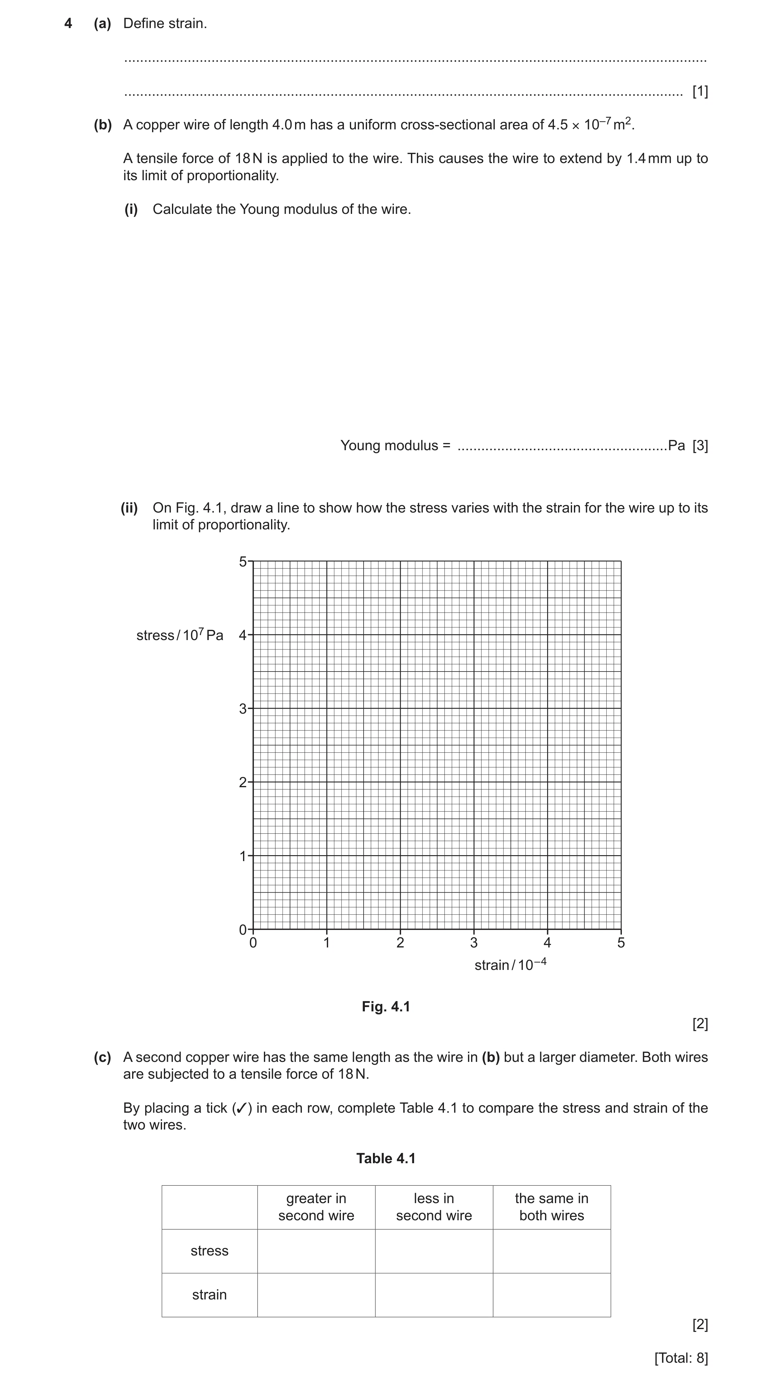
4 (a) Define strain. … … [1] (b) A copper wire of length 4.0 m has a uniform cross-sectional area of 4.5 × 10⁻⁷ m2. A tensile force of 18 N is applied to the wire. This causes the wire to extend by 1.4 mm up to its limit of proportionality. (i) Calculate the Young modulus of the wire. Young modulus = … Pa [3] (ii) On Fig. 4.1, draw a line to show how the stress varies with the strain for the wire up to its limit of proportionality. 5 stress / 107 Pa 4 3 2 1 0 0 1 2 3 4 5 strain / 10 – 4 Fig. 4.1 [2] (c) A second copper wire has the same length as the wire in (b) but a larger diameter. Both wires are subjected to a tensile force of 18 N. By placing a tick (3) in each row, complete Table 4.1 to compare the stress and strain of the two wires. Table 4.1 greater in less in the same in second wire second wire both wires stress strain [2] [Total: 8]
8 marks
Mark scheme: 4(a) extension / original length B1 4(b)(i) Young modulus = stress / strain C1 = (18 / 4.5 10–7) / (1.4 10–3 / 4.0) C1 = (4.0 107) / (3.5 10–4) = 1.1 1011 Pa A1 4(b)(ii) straight line through the origin B1 ending at the point (3.5, 4.0) B1 4(c) greater in second wire less in second wire the same in both wires stress strain B2
This question in 9702/21 May/June 2024
Q13 · Lightning occurs when charge builds up in the atmosphere, creating a potential difference… 9702/22 May/June 2024
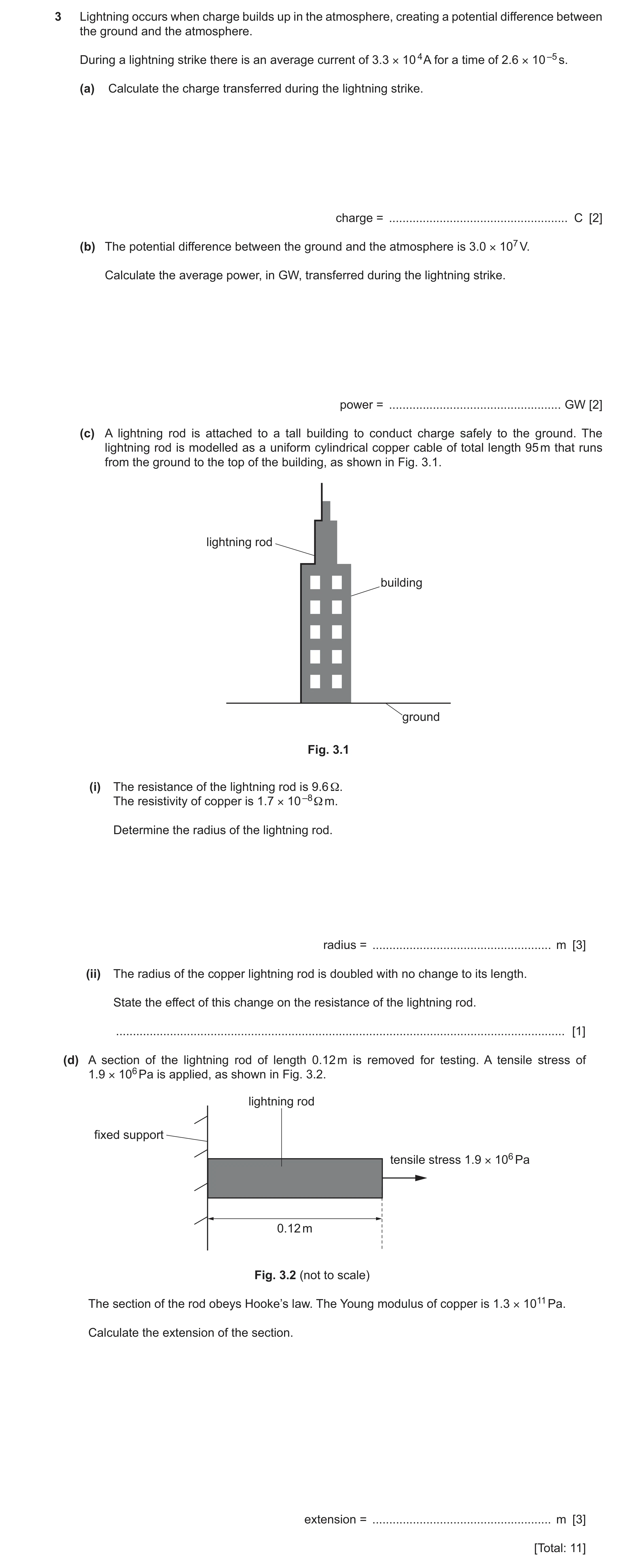
3 Lightning occurs when charge builds up in the atmosphere, creating a potential difference between the ground and the atmosphere. During a lightning strike there is an average current of 3.3 × 10 4 A for a time of 2.6 × 10 –5 s. (a) Calculate the charge transferred during the lightning strike. charge = … C [2] (b) The potential difference between the ground and the atmosphere is 3.0 × 10⁷ V. Calculate the average power, in GW, transferred during the lightning strike. power = … GW [2] (c) A lightning rod is attached to a tall building to conduct charge safely to the ground. The lightning rod is modelled as a uniform cylindrical copper cable of total length 95 m that runs from the ground to the top of the building, as shown in Fig. 3.1. lightning rod building ground Fig. 3.1 (i) The resistance of the lightning rod is 9.6 Ω. The resistivity of copper is 1.7 × 10 –8 Ω m. Determine the radius of the lightning rod. radius = … m [3] (ii) The radius of the copper lightning rod is doubled with no change to its length. State the effect of this change on the resistance of the lightning rod. … [1] (d) A section of the lightning rod of length 0.12 m is removed for testing. A tensile stress of 1.9 × 10⁶ Pa is applied, as shown in Fig. 3.2. lightning rod fixed support tensile stress 1.9 × 10⁶ Pa 0.12 m Fig. 3.2 (not to scale) The section of the rod obeys Hooke’s law. The Young modulus of copper is 1.3 × 10¹¹ Pa. Calculate the extension of the section. extension = … m [3] [Total: 11]
11 marks
Mark scheme: 3(a) C1 = 3.3 104 2.6 10–5 = 0.86 C A1 3(b) P = IV or P = VQ / t or V = IR and P = V 2/R or P = I 2R C1 P = 3.3 104 3.0 107 or P = (3.0 107 0.86) / (2.6 10–5) or P = (3.0 107)2 / 910 or P = (3.3 104)2 910 P = 9.9 1011 (W) = 990 GW A1 3(c)(i) R = L / A C1 9.6 = 1.7 10–8 95 / r 2 C1 r = 2.3 10–4 m A1 3(c)(ii) (resistance) decreases by a factor of four A1 Question Answer Marks 3(d) E = / C1 x = L / E = 1.9 106 0.12 / (1.3 1011) C1 = 1.8 10–6 m A1
This question in 9702/22 May/June 2024
Question 14 9702/23 May/June 2024
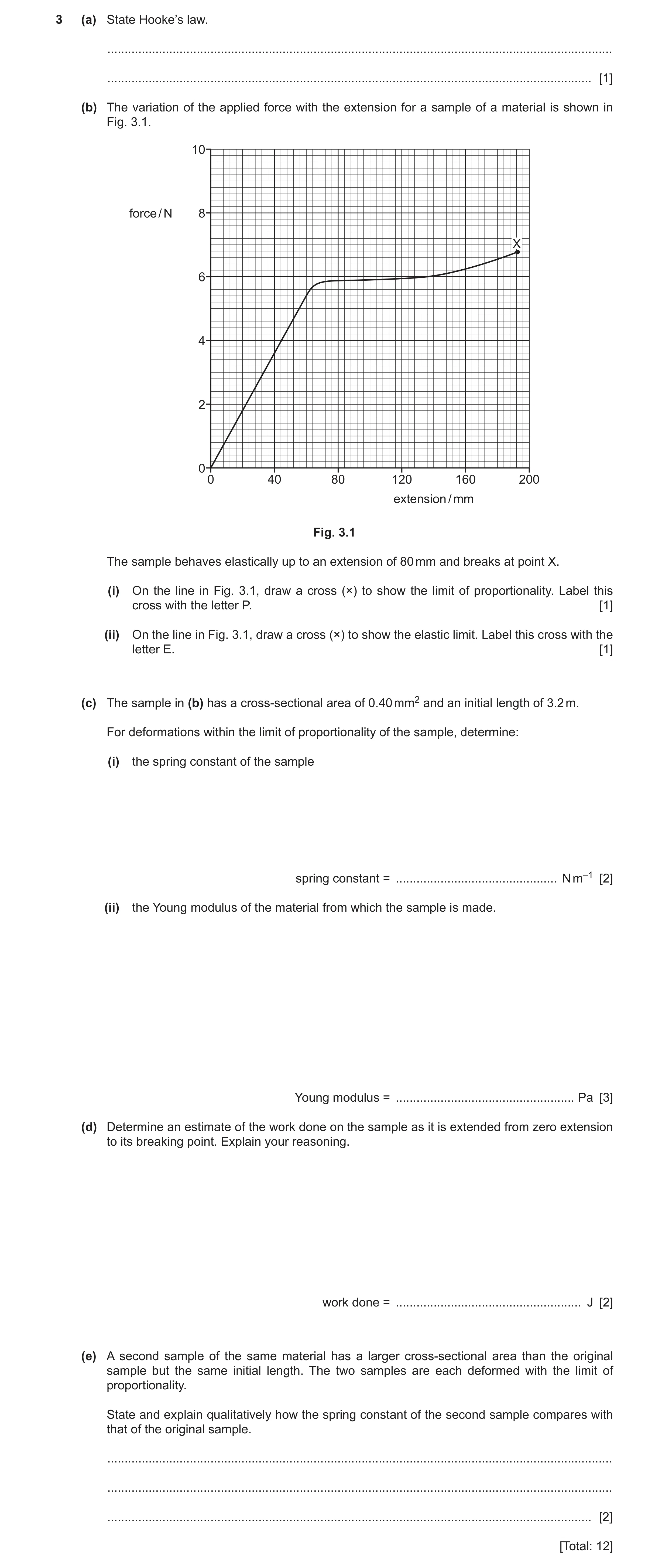
3 (a) State Hooke’s law. … … [1] (b) The variation of the applied force with the extension for a sample of a material is shown in Fig. 3.1. 10 force / N 8 X 6 4 2 0 0 40 80 120 160 200 extension / mm Fig. 3.1 The sample behaves elastically up to an extension of 80 mm and breaks at point X. (i) On the line in Fig. 3.1, draw a cross (×) to show the limit of proportionality. Label this cross with the letter P. [1] (ii) On the line in Fig. 3.1, draw a cross (×) to show the elastic limit. Label this cross with the letter E. [1] (c) The sample in (b) has a cross-sectional area of 0.40 mm2 and an initial length of 3.2 m. For deformations within the limit of proportionality of the sample, determine: (i) the spring constant of the sample spring constant = … N m–1 [2] (ii) the Young modulus of the material from which the sample is made. Young modulus = … Pa [3] (d) Determine an estimate of the work done on the sample as it is extended from zero extension to its breaking point. Explain your reasoning. work done = … J [2] (e) A second sample of the same material has a larger cross-sectional area than the original sample but the same initial length. The two samples are each deformed with the limit of proportionality. State and explain qualitatively how the spring constant of the second sample compares with that of the original sample. … … … [2] [Total: 12]
12 marks
Mark scheme: 3(a) extension is proportional to (applied) force B1 3(b)(i) P at (60, 5.4) A1 3(b)(ii) E at (80, 5.9) A1 3(c)(i) k = F / x or k = gradient of (straight line section of) graph C1 e.g. gradient = 5.4 / 0.060 k = 90 N m–1 A1 3(c)(ii) Young modulus or E = / or FL / Ax or kL / A C1 E = (5.4 3.2) / (4.0 10−7 0.06) or 90 3.2 / (4.0 10−7) C1 E = 7.2 108 Pa A1 3(d) work done = area under graph B1 = (1.0 0.2) J A1 3(e) the extension will be smaller (for the same force on the thicker sample) or a greater force is required (to extend the thicker sample by the same amount) or spring constant is proportional to area M1 the spring constant (of the second sample) will be greater A1
This question in 9702/23 May/June 2024
Q15 · Define: (i) stress … … [1] (ii) strain 9702/23 Oct/Nov 2024
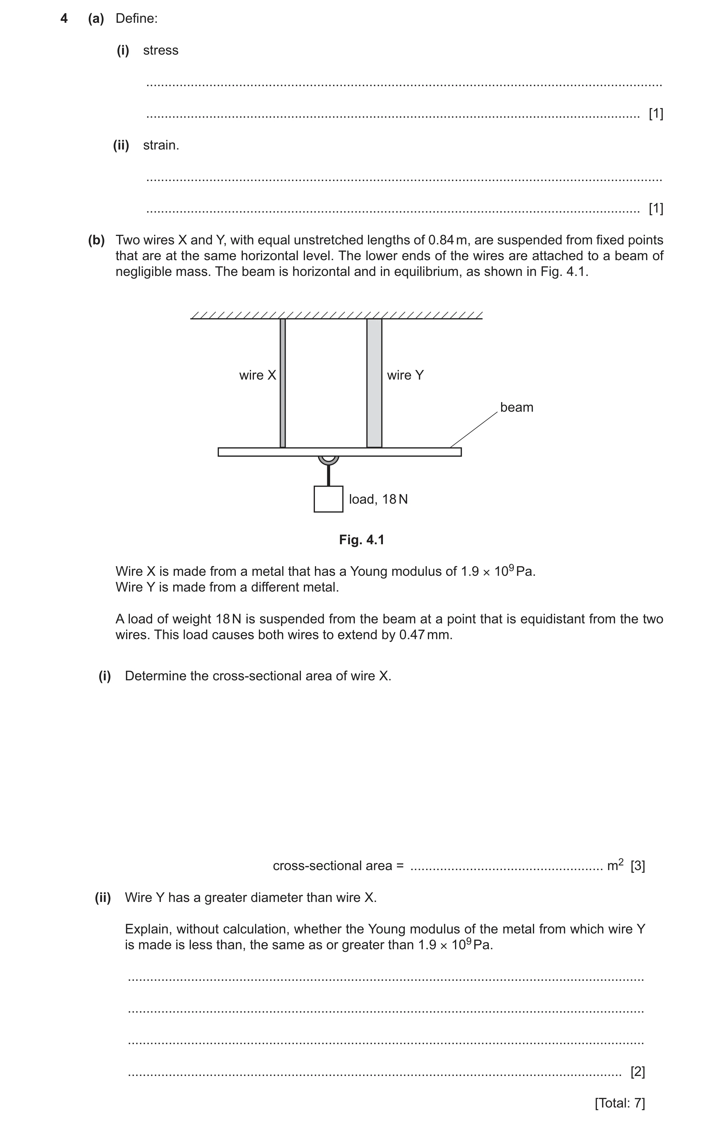
4 (a) Define: (i) stress … … [1] (ii) strain. … … [1] (b) Two wires X and Y, with equal unstretched lengths of 0.84 m, are suspended from fixed points that are at the same horizontal level. The lower ends of the wires are attached to a beam of negligible mass. The beam is horizontal and in equilibrium, as shown in Fig. 4.1. wire X wire Y beam load, 18 N Fig. 4.1 Wire X is made from a metal that has a Young modulus of 1.9 × 10⁹ Pa. Wire Y is made from a different metal. A load of weight 18 N is suspended from the beam at a point that is equidistant from the two wires. This load causes both wires to extend by 0.47 mm. (i) Determine the cross-sectional area of wire X. cross-sectional area = … m2 [3] (ii) Wire Y has a greater diameter than wire X. Explain, without calculation, whether the Young modulus of the metal from which wire Y is made is less than, the same as or greater than 1.9 × 10⁹ Pa. … … … … [2] [Total: 7]
7 marks
Mark scheme: 4(a)(i) (normal) force per unit cross-sectional area B1 4(a)(ii) extension per unit unstretched length B1 4(b)(i) E = FL / Ax C1 A = (9.0 0.84) / (1.9 109 0.47 10–3) C1 = 8.5 10–6 m2 A1 4(b)(ii) F, L and x are all the same (for both wires / as in X) B1 or F and strain are the same A is greater (for Y), so the Young modulus (for Y) is less than 1.9 109 Pa or less than that of wire X B1
This question in 9702/23 Oct/Nov 2024
Q16 · Define the Young modulus 9702/22 May/June 2025
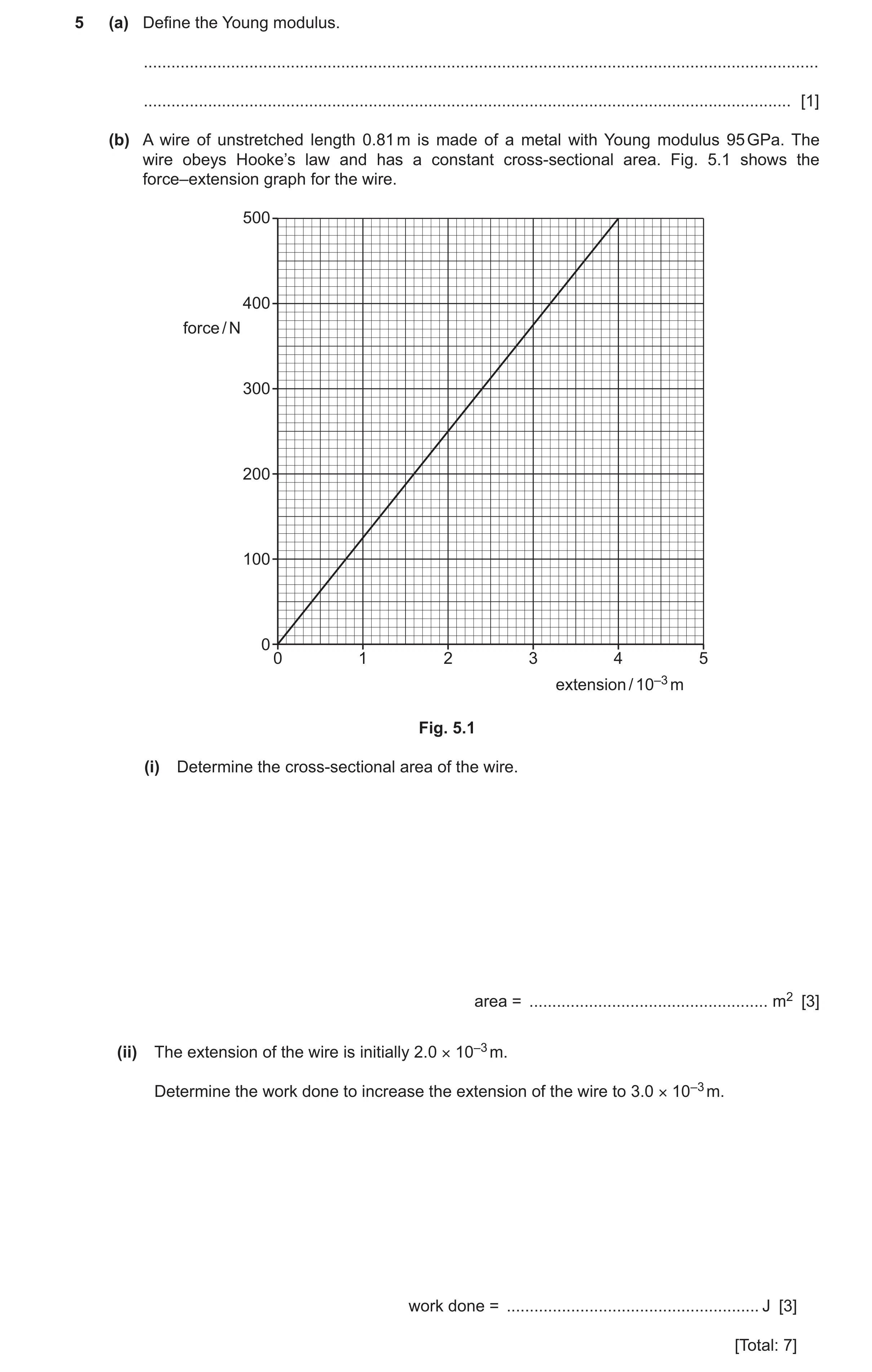
5 (a) Define the Young modulus. … … [1] (b) A wire of unstretched length 0.81 m is made of a metal with Young modulus 95 GPa. The wire obeys Hooke’s law and has a constant cross-sectional area. Fig. 5.1 shows the force–extension graph for the wire. 500 400 force / N 300 200 100 0 0 1 2 3 4 5 extension / 10–3 m Fig. 5.1 (i) Determine the cross-sectional area of the wire. area = … m2 [3] (ii) The extension of the wire is initially 2.0 × 10⁻³ m. Determine the work done to increase the extension of the wire to 3.0 × 10⁻³ m. work done = … J [3] [Total: 7]
7 marks
Mark scheme: 5(a) the ratio of stress to strain B1 5(b)(i) A = FL / Ex C1 A = e.g. (500 0.81) / (95 109 4.0 10–3) C1 A = 1.1 10–6 m2 A1 OR (C1) A = kL / E or A = gradient L / E k = e.g. 500 / 4.0 10–3 k = 1.25 105 A = 1.25 105 0.81 / 95 109 (C1) A = 1.1 10–6 m2 (A1) 5(b)(ii) E = ½ kx2 or E = ½ Fx or E = area (under graph) C1 ()E = ½ 1.25 105 ((3.0 10–3)2 – (2.0 10–3)2) C1 or ()E =(½ 375 3.0 10–3) – (½ 250 2.0 10–3) or ()E = ½ (375 + 250) 1.0 10–3 work done = 0.31 J A1
This question in 9702/22 May/June 2025
Q17 · A wire has length L and cross-sectional area A 9702/23 Oct/Nov 2025
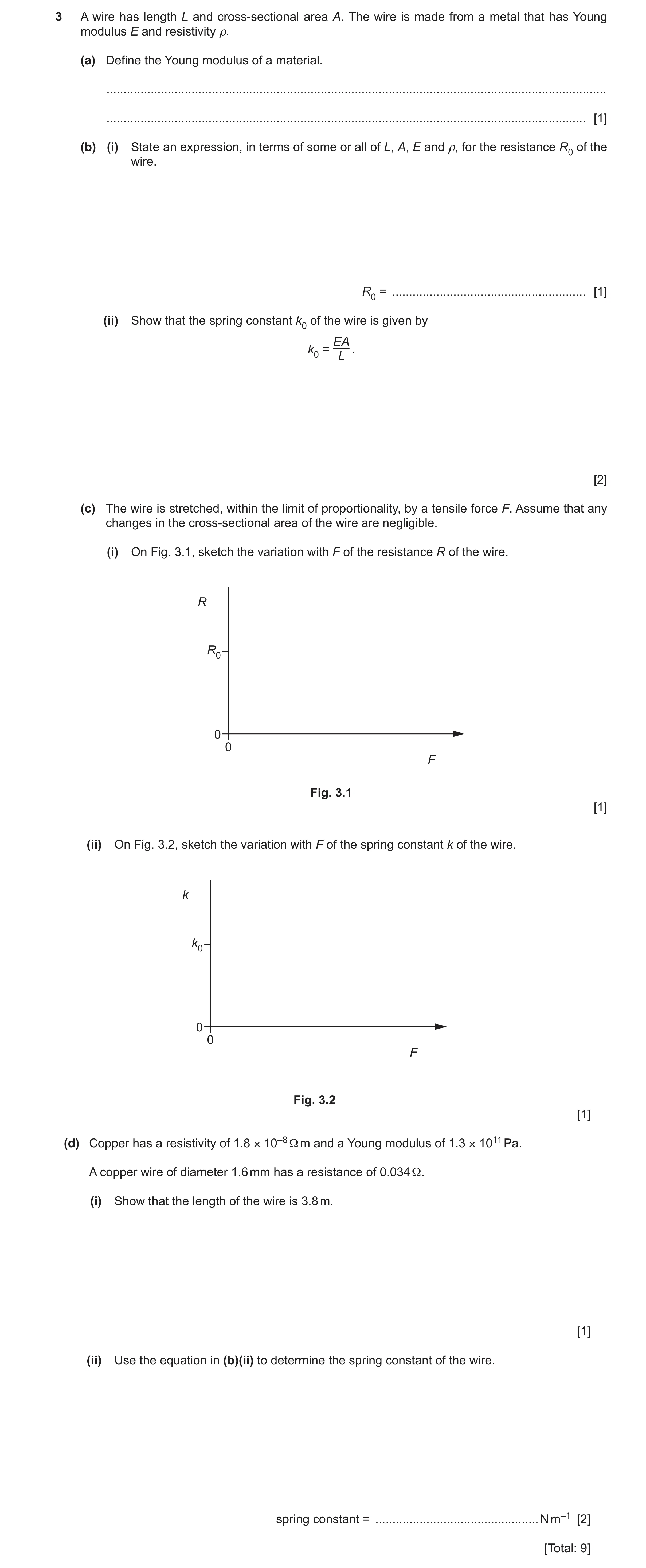
3 A wire has length L and cross-sectional area A. The wire is made from a metal that has Young modulus E and resistivity ρ. (a) Define the Young modulus of a material. … … [1] (b) (i) State an expression, in terms of some or all of L, A, E and ρ, for the resistance R0 of the wire. R0 = … [1] (ii) Show that the spring constant k0 of the wire is given by EA k0 = L . [2] (c) The wire is stretched, within the limit of proportionality, by a tensile force F. Assume that any changes in the cross-sectional area of the wire are negligible. (i) On Fig. 3.1, sketch the variation with F of the resistance R of the wire. R R0 0 0 F Fig. 3.1 [1] (ii) On Fig. 3.2, sketch the variation with F of the spring constant k of the wire. k k0 0 0 F Fig. 3.2 [1] (d) Copper has a resistivity of 1.8 × 10⁻⁸ Ω m and a Young modulus of 1.3 × 10¹¹ Pa. A copper wire of diameter 1.6 mm has a resistance of 0.034 Ω. (i) Show that the length of the wire is 3.8 m. [1] (ii) Use the equation in (b)(ii) to determine the spring constant of the wire. spring constant = … N m–1 [2] [Total: 9]
9 marks
Mark scheme: 3(a) ratio of stress to strain B1 3(b)(i) R0 = L / A A1 3(b)(ii) k = F / x C1 E = FL / Ax = ((F / x) (L / A)) = kL / A leading to k0 = EA / L A1 3(c)(i) straight line with positive gradient starting at (0, R0) B1 3(c)(ii) straight horizontal line starting at (0, k0) B1 3(d)(i) L = [0.034 (0.80 10–3)2] / 1.8 10–8 = 3.8 (m) A1 3(d)(ii) k = [1.3 1011 (0.80 10–3)2] / 3.8 C1 or k = EA / [RA / ] = E / R = [1.3 1011 1.8 10–8] / 0.034 k = 6.9 104 N m–1 A1
This question in 9702/23 Oct/Nov 2025
 1 / 29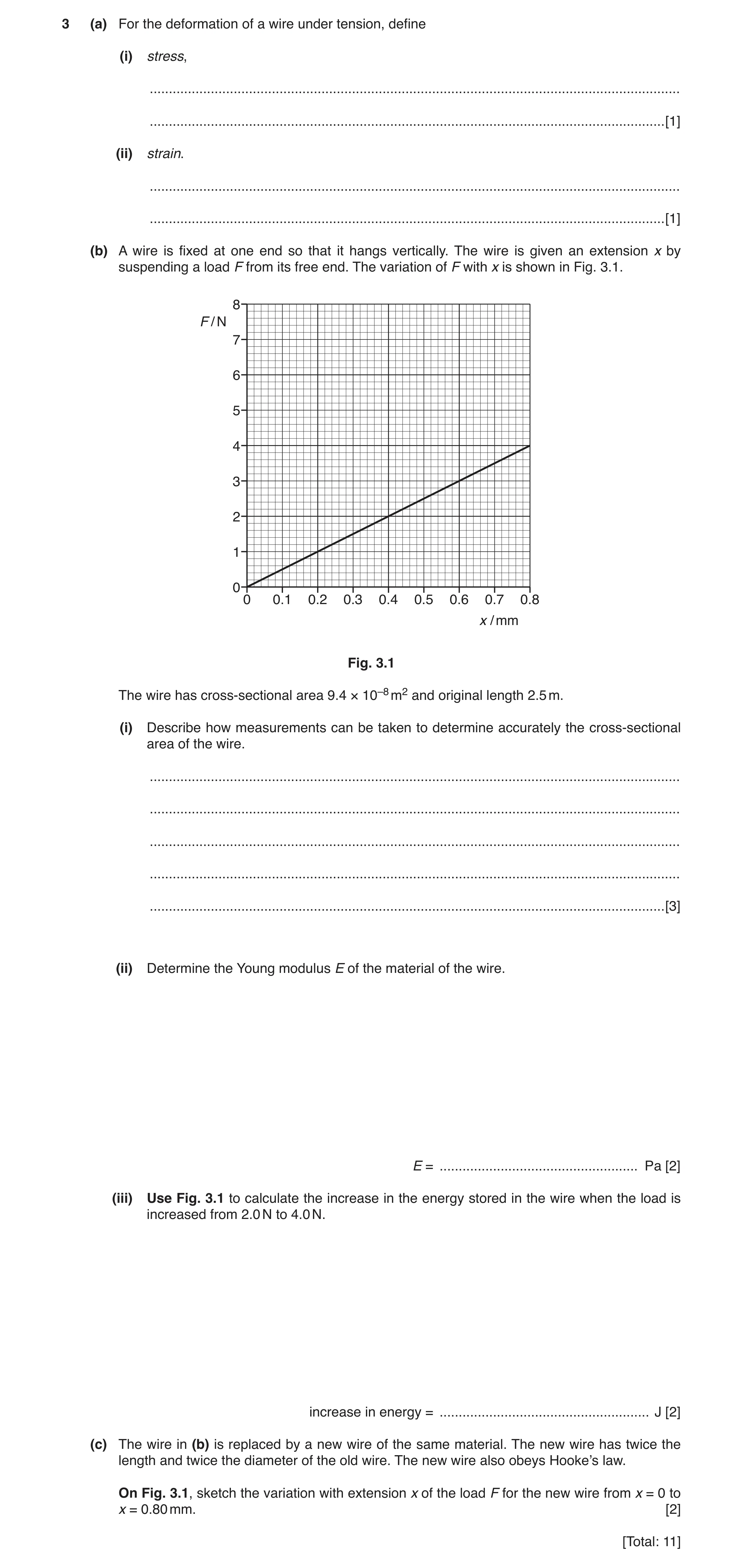
 5
5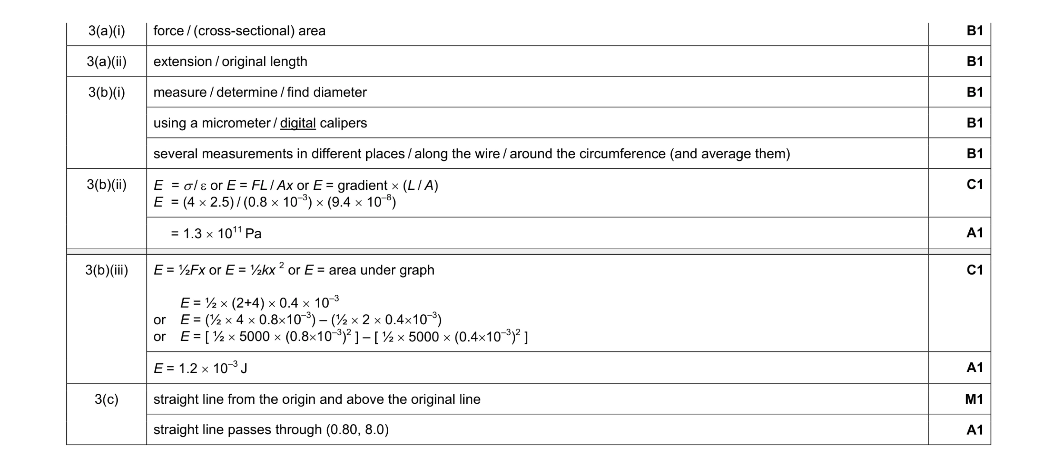 11
11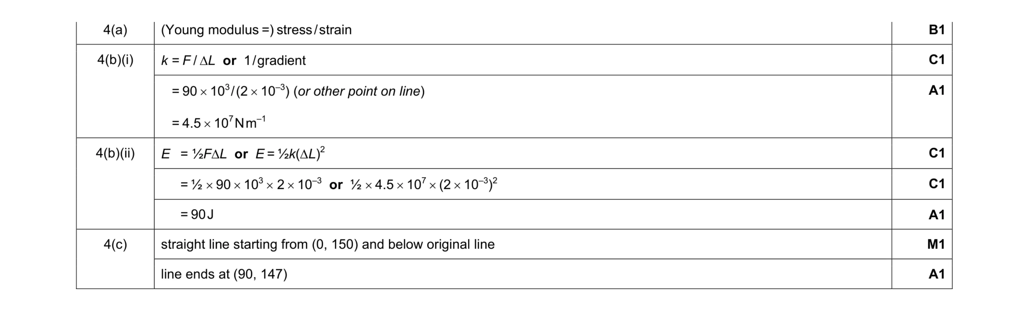 8
8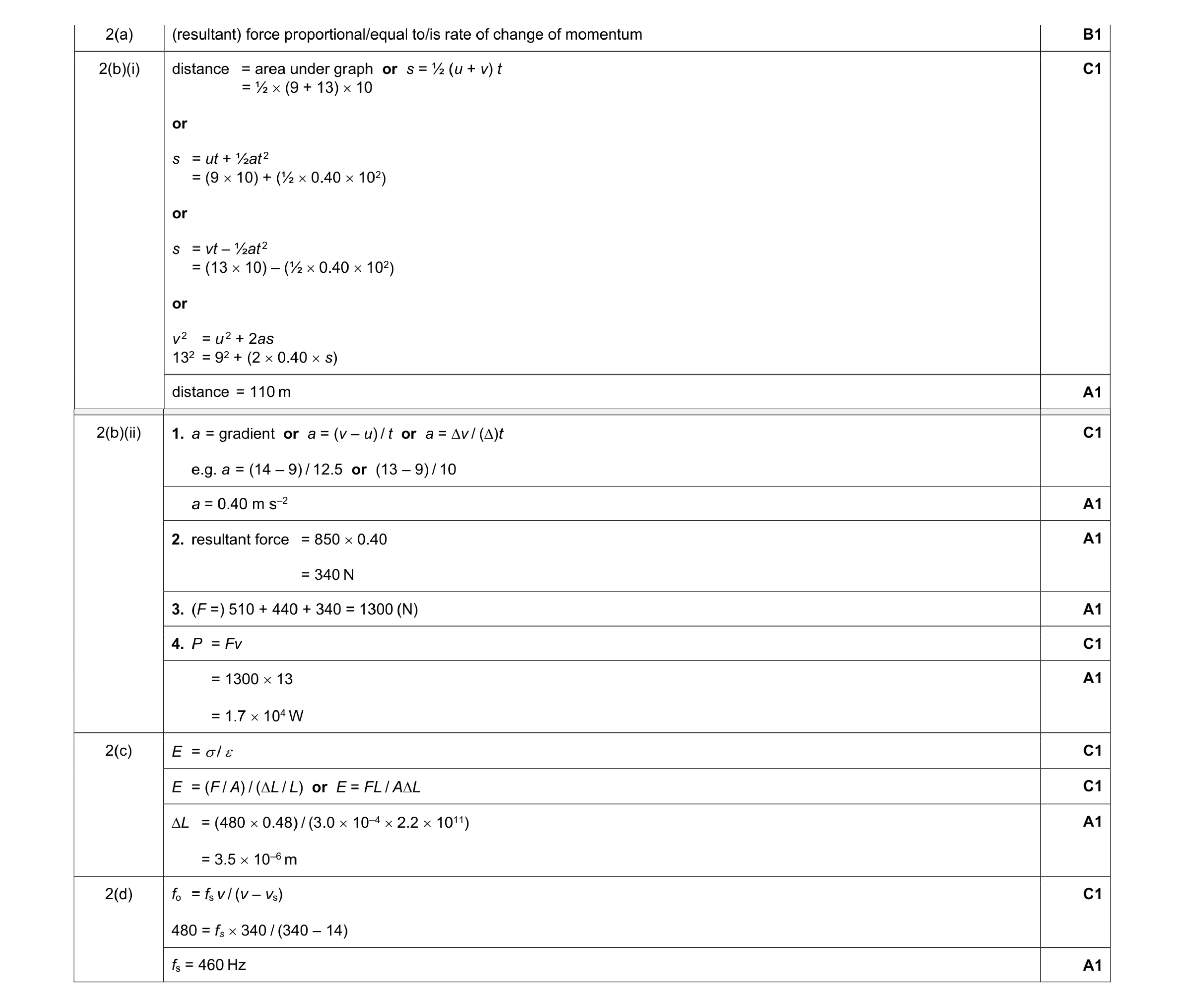 14
14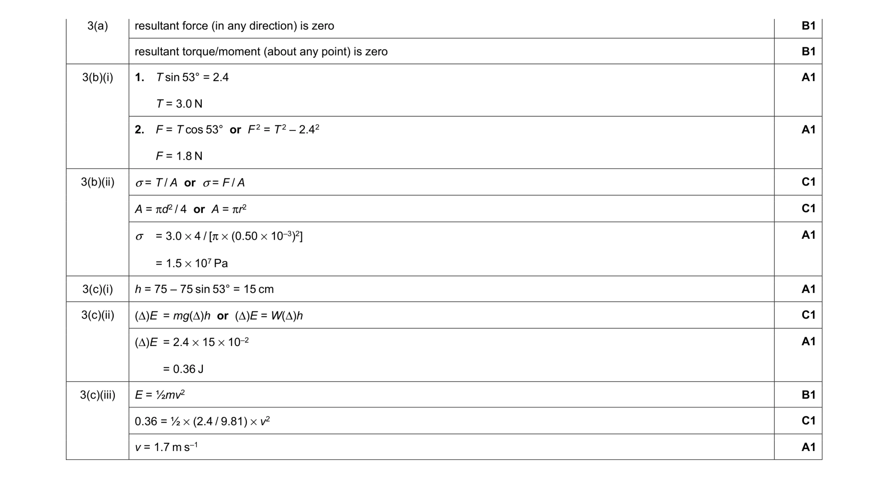 13
13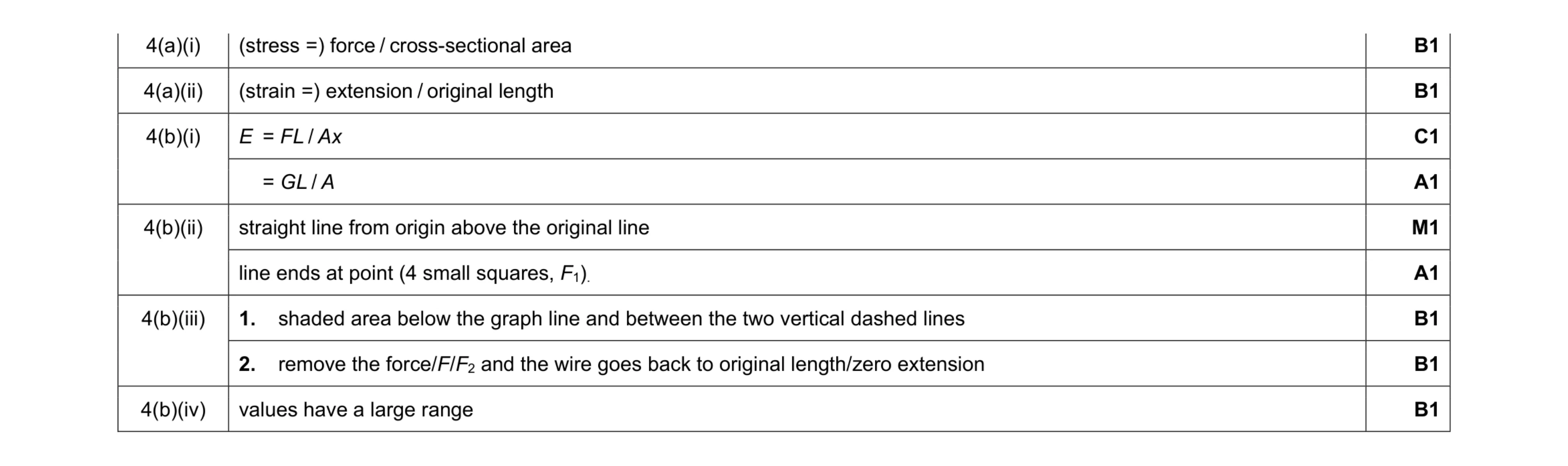 9
9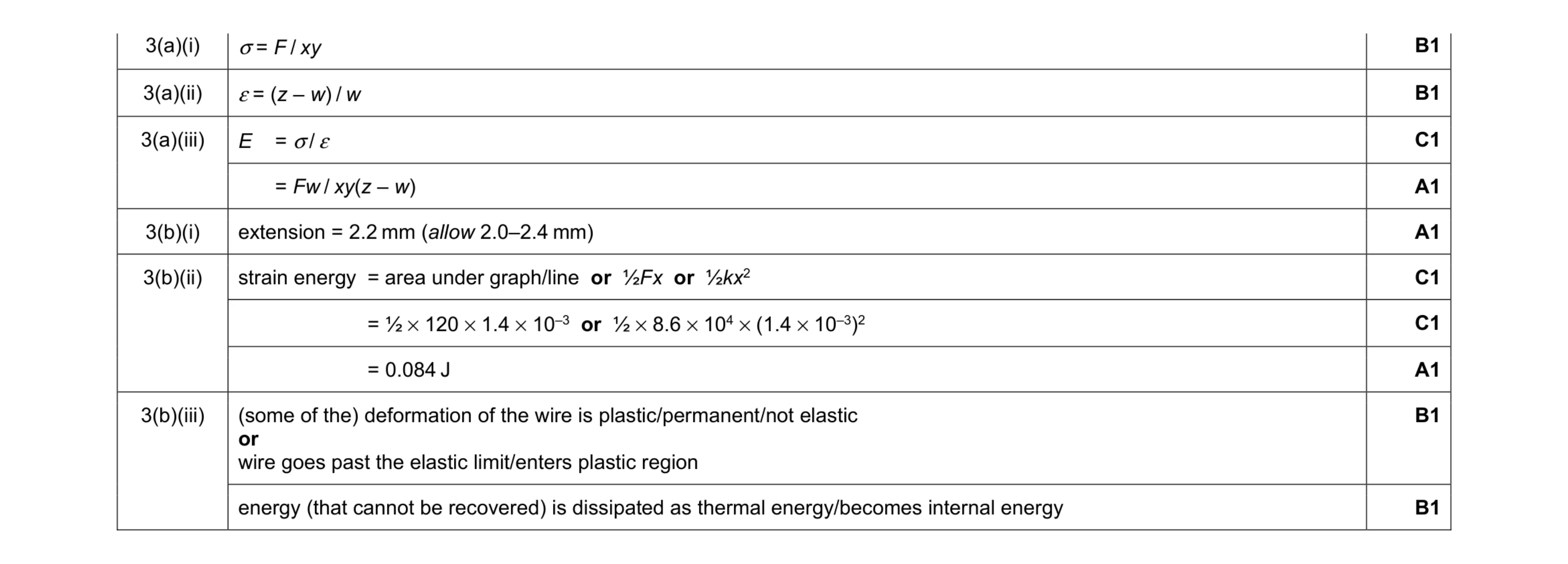 10
10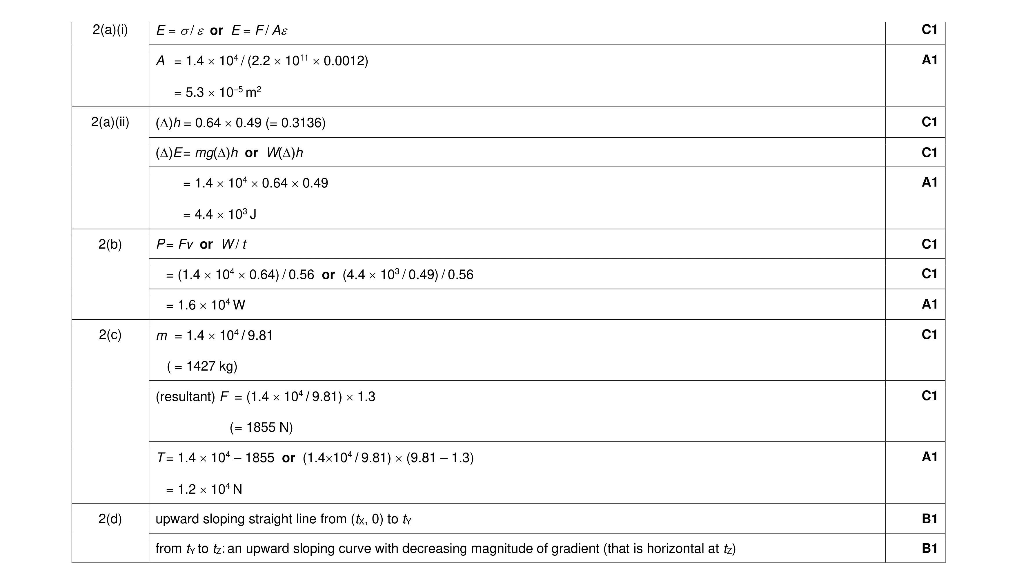 13
13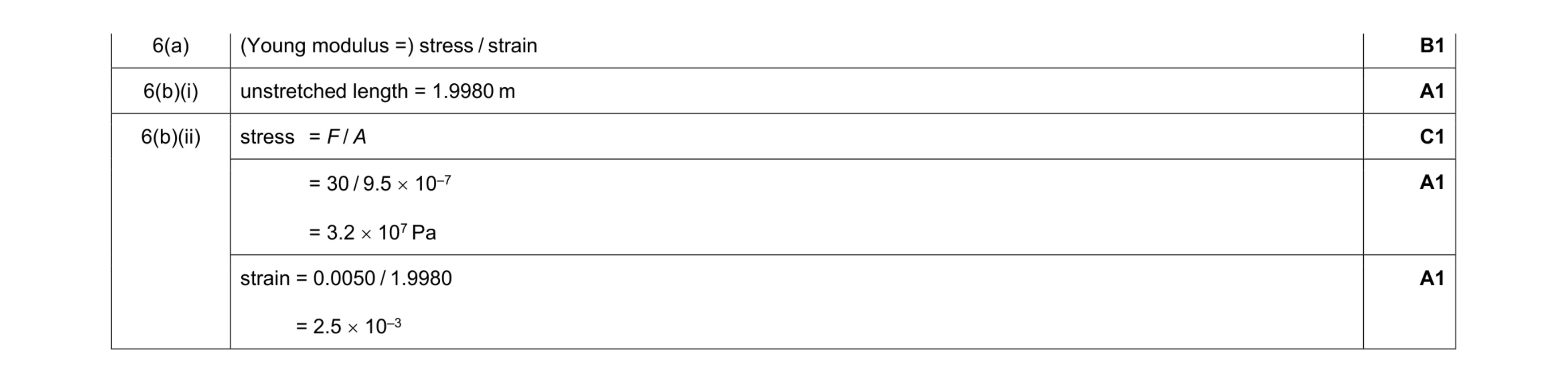 5
5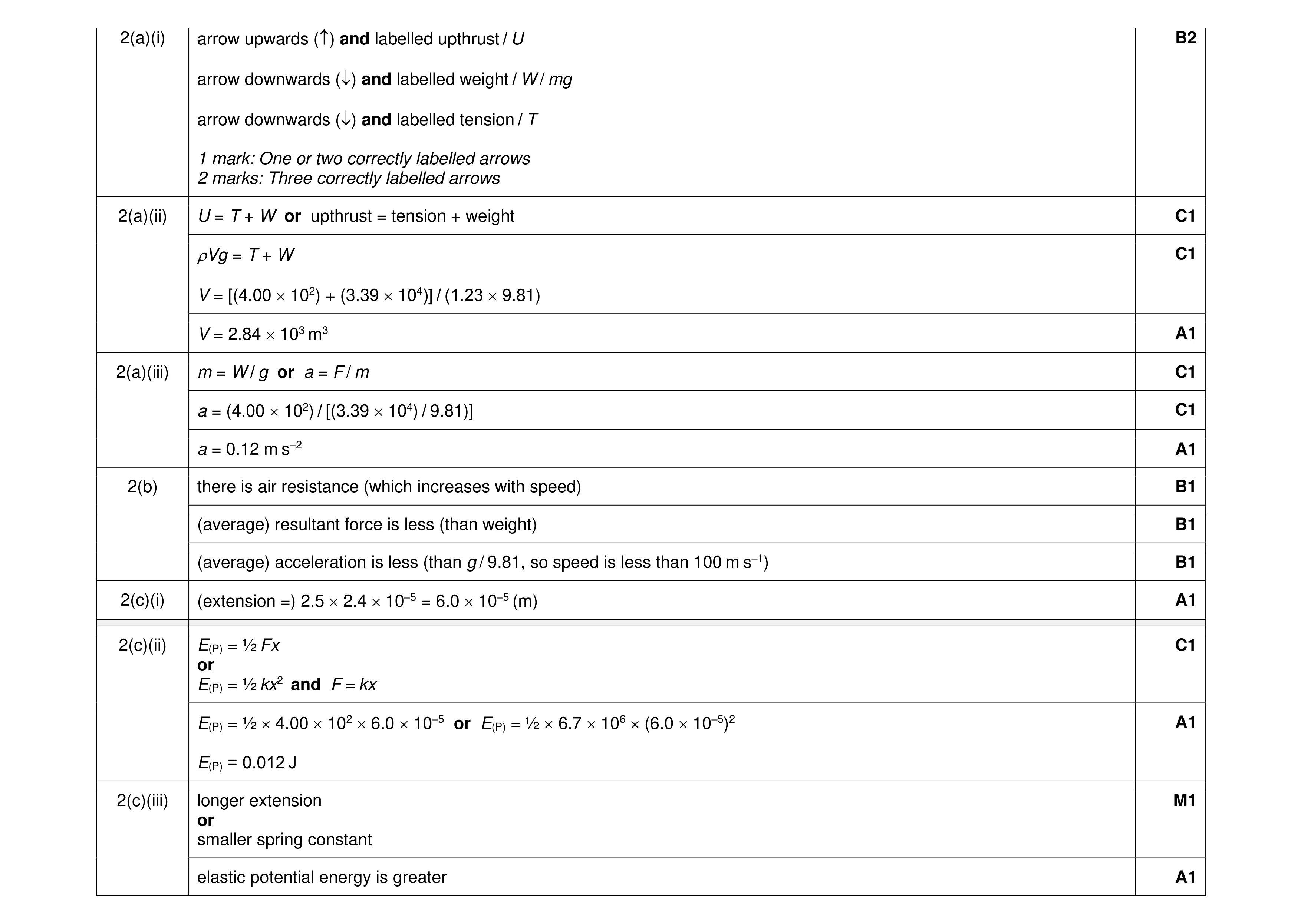 16
16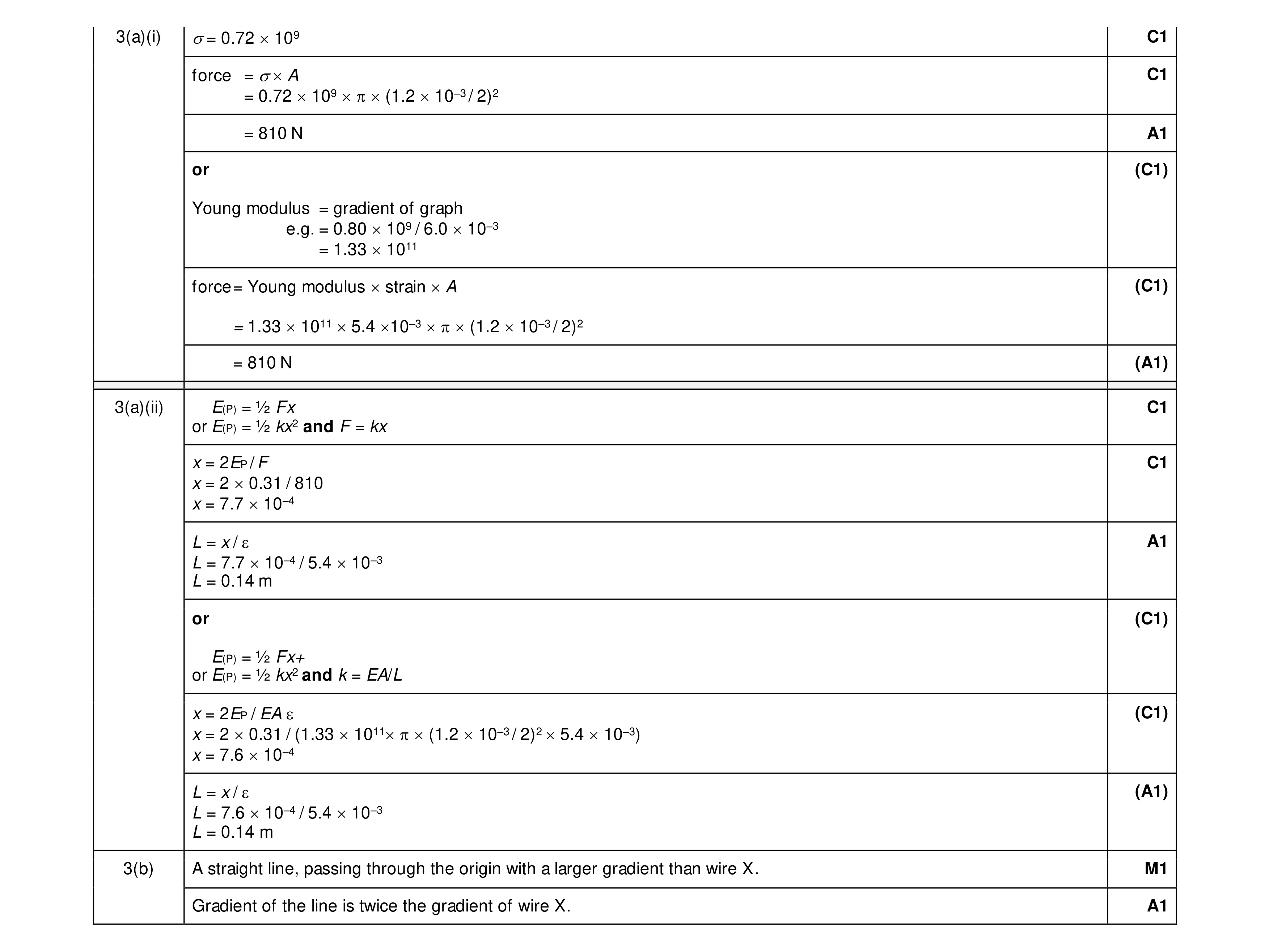 8
8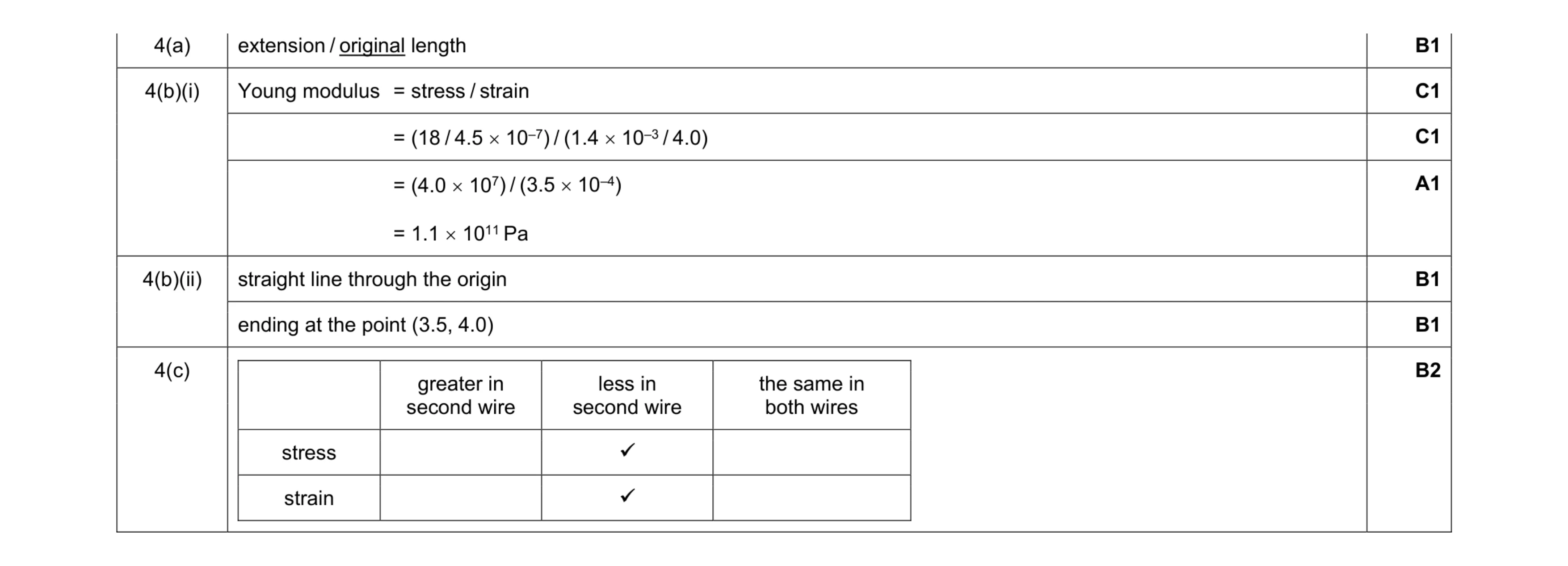 8
8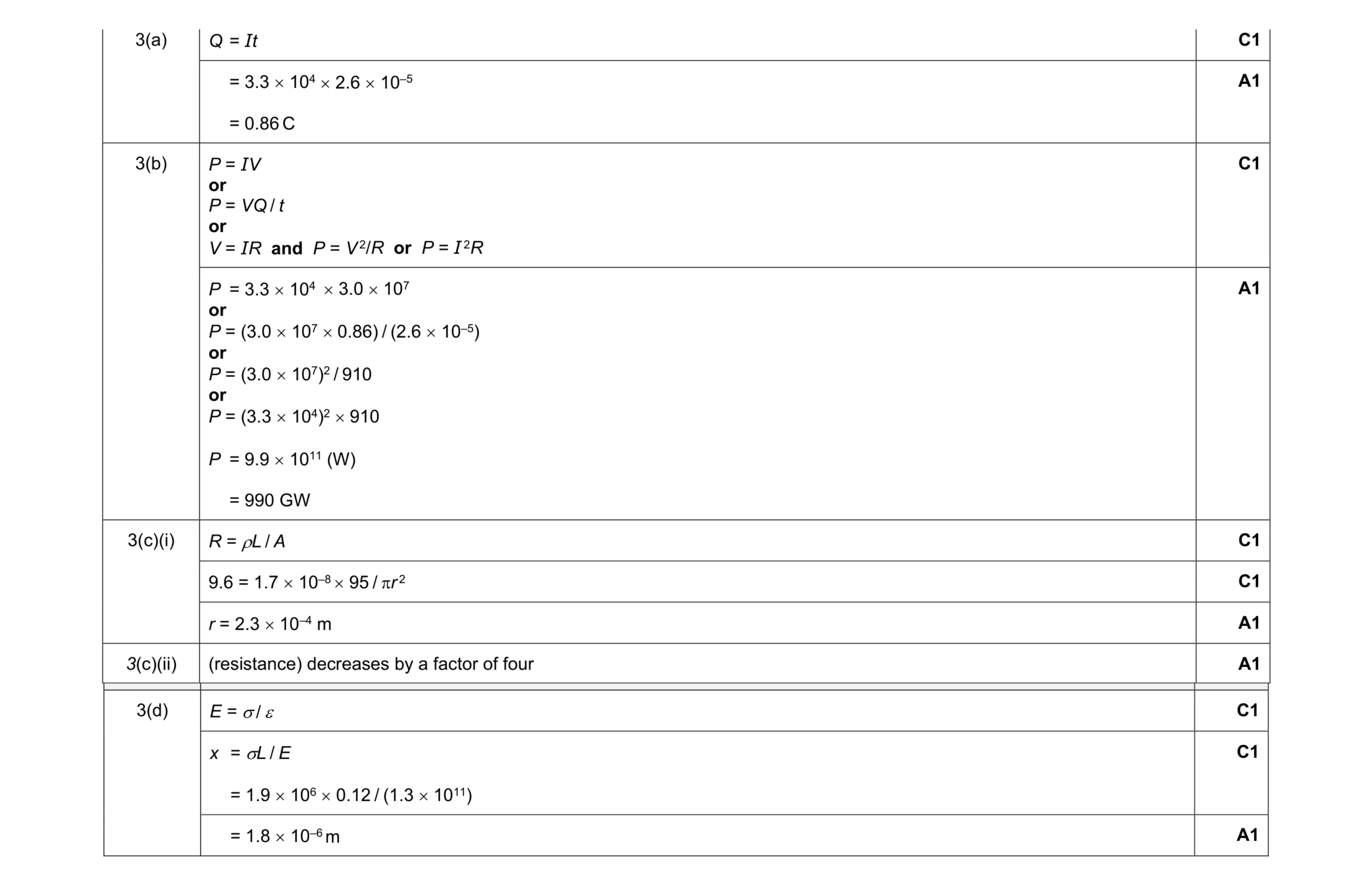 11
11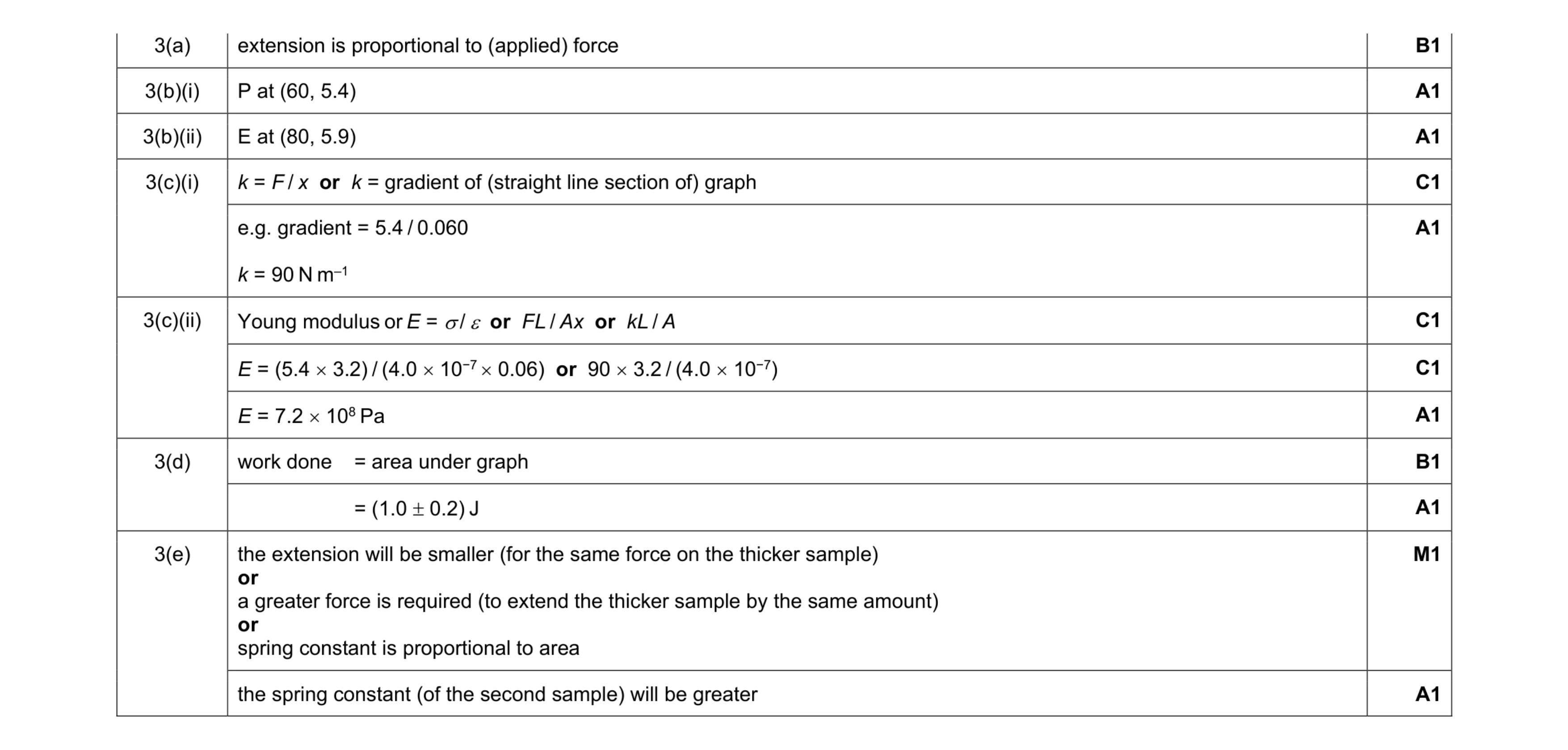 12
12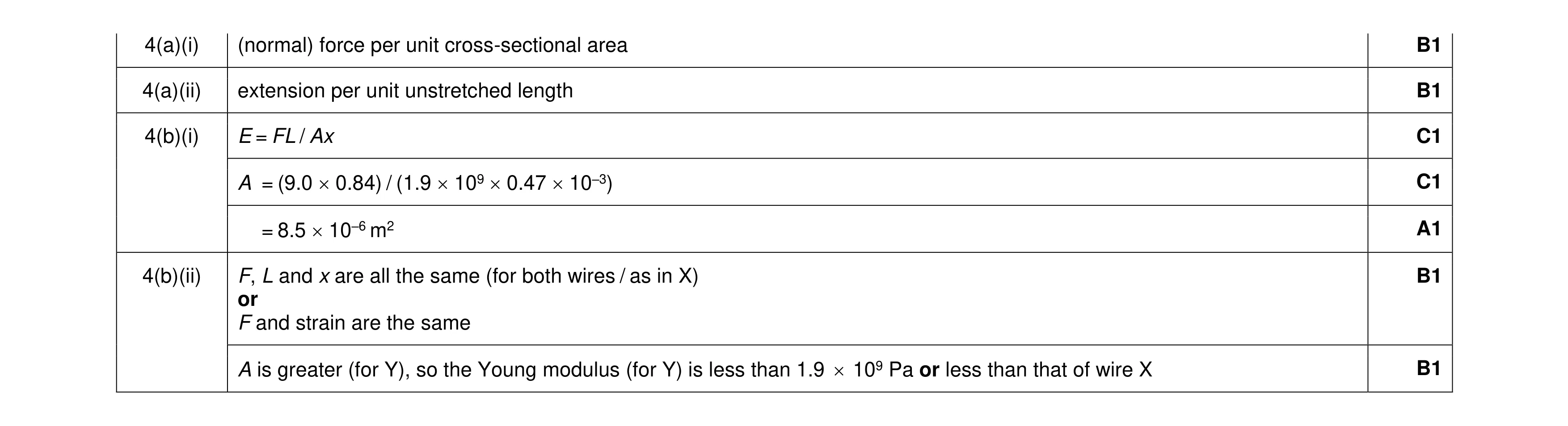 7
7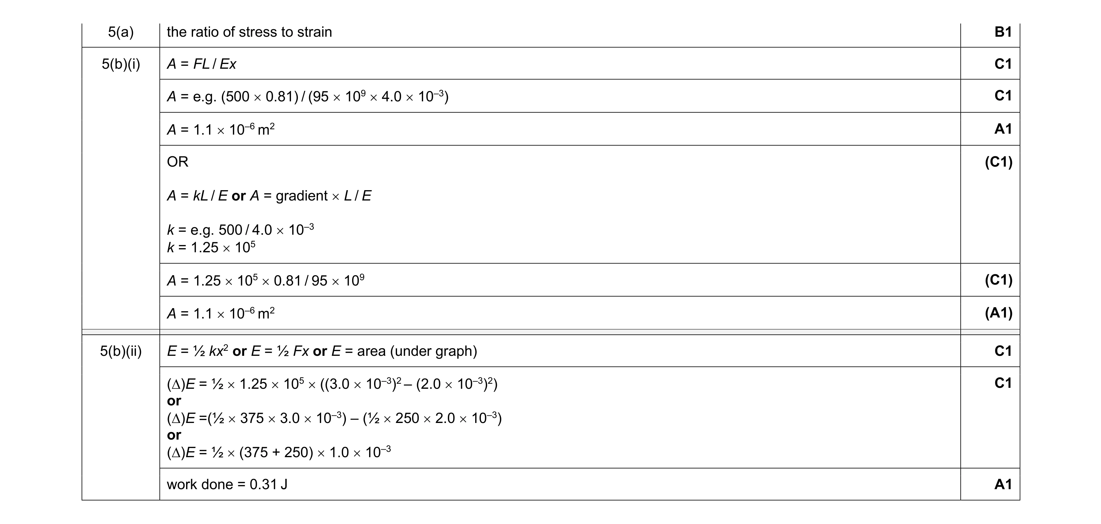 7
7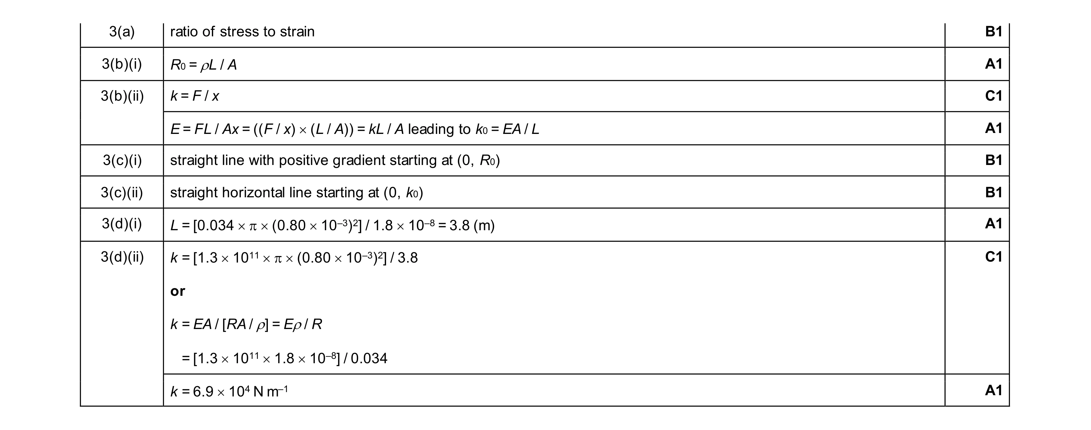 9
9