Questions as text
Q1 · State what is meant by a magnetic field 9702/42 Feb/March 2017
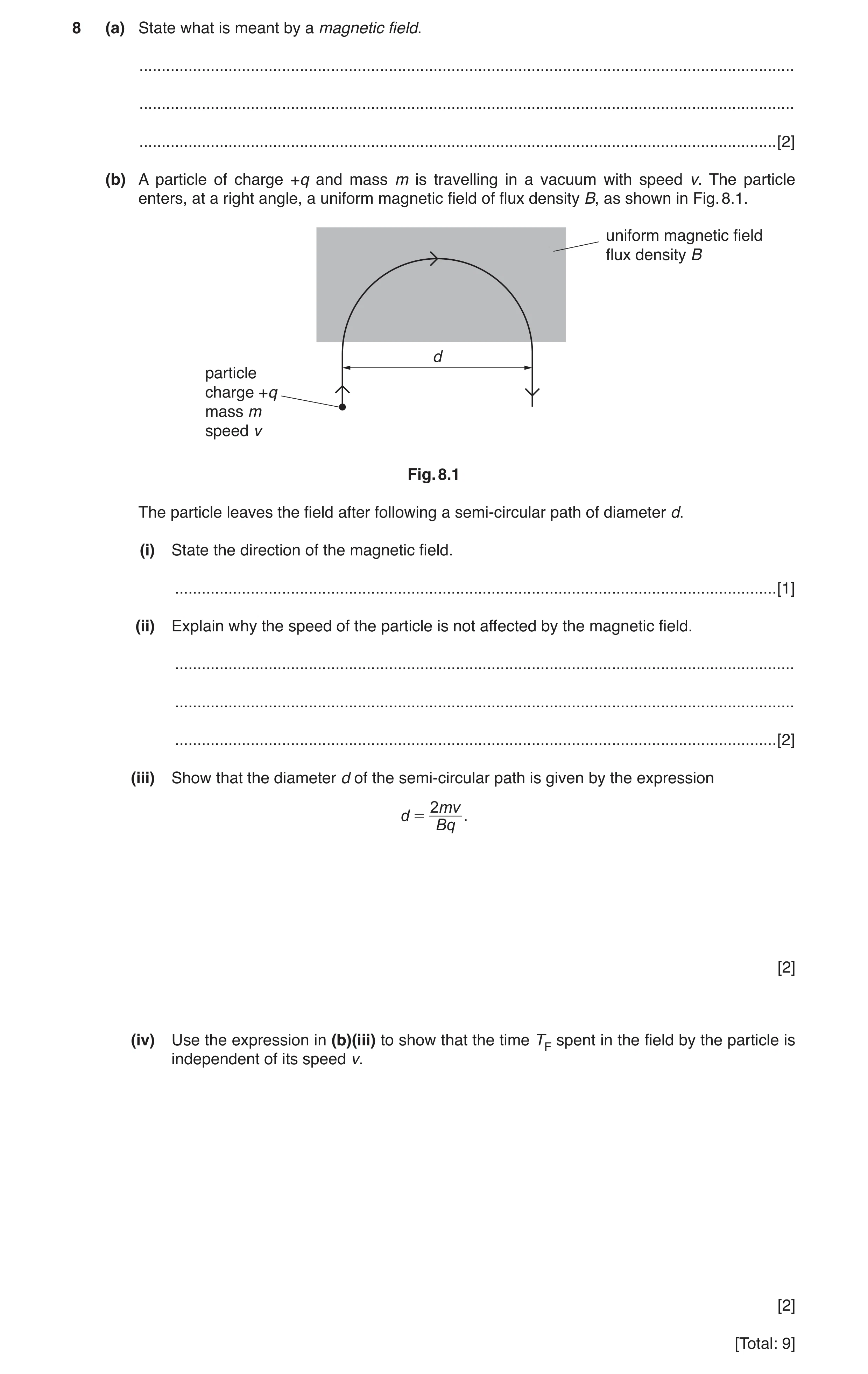
8 (a) State what is meant by a magnetic field. … … … [2] (b) A particle of charge +q and mass m is travelling in a vacuum with speed v. The particle enters, at a right angle, a uniform magnetic field of flux density B, as shown in Fig. 8.1. uniform magnetic field flux density B d particle charge +q mass m speed v Fig. 8.1 The particle leaves the field after following a semi-circular path of diameter d. (i) State the direction of the magnetic field. … [1] (ii) Explain why the speed of the particle is not affected by the magnetic field. … … … [2] (iii) Show that the diameter d of the semi-circular path is given by the expression 2 mv d = . Bq [2] (iv) Use the expression in (b)(iii) to show that the time TF spent in the field by the particle is independent of its speed v. [2] [Total: 9]
9 marks
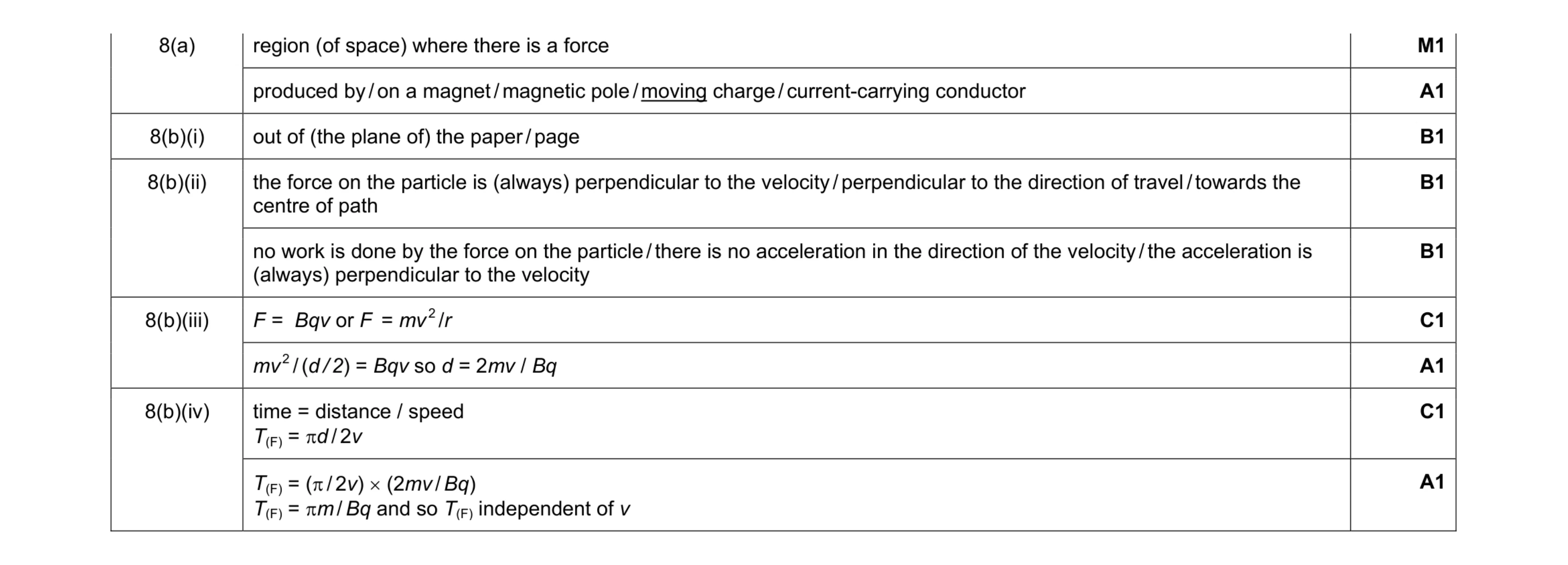
Mark scheme: 8(a) region (of space) where there is a force M1 produced by / on a magnet / magnetic pole / moving charge / current-carrying conductor A1 8(b)(i) out of (the plane of) the paper / page B1 8(b)(ii) the force on the particle is (always) perpendicular to the velocity / perpendicular to the direction of travel / towards the centre of path B1 no work is done by the force on the particle / there is no acceleration in the direction of the velocity / the acceleration is (always) perpendicular to the velocity B1 8(b)(iii) F = Bqv or F = mv 2 /r C1 mv 2 / (d / 2) = Bqv so d = 2mv / Bq A1 8(b)(iv) time = distance / speed T(F) = πd / 2v C1 T(F) = (π / 2v) × (2mv / Bq) T(F) = πm / Bq and so T(F) independent of v A1
This question in 9702/42 Feb/March 2017
Q2 · Explain what is meant by a magnetic field 9702/41 Oct/Nov 2018
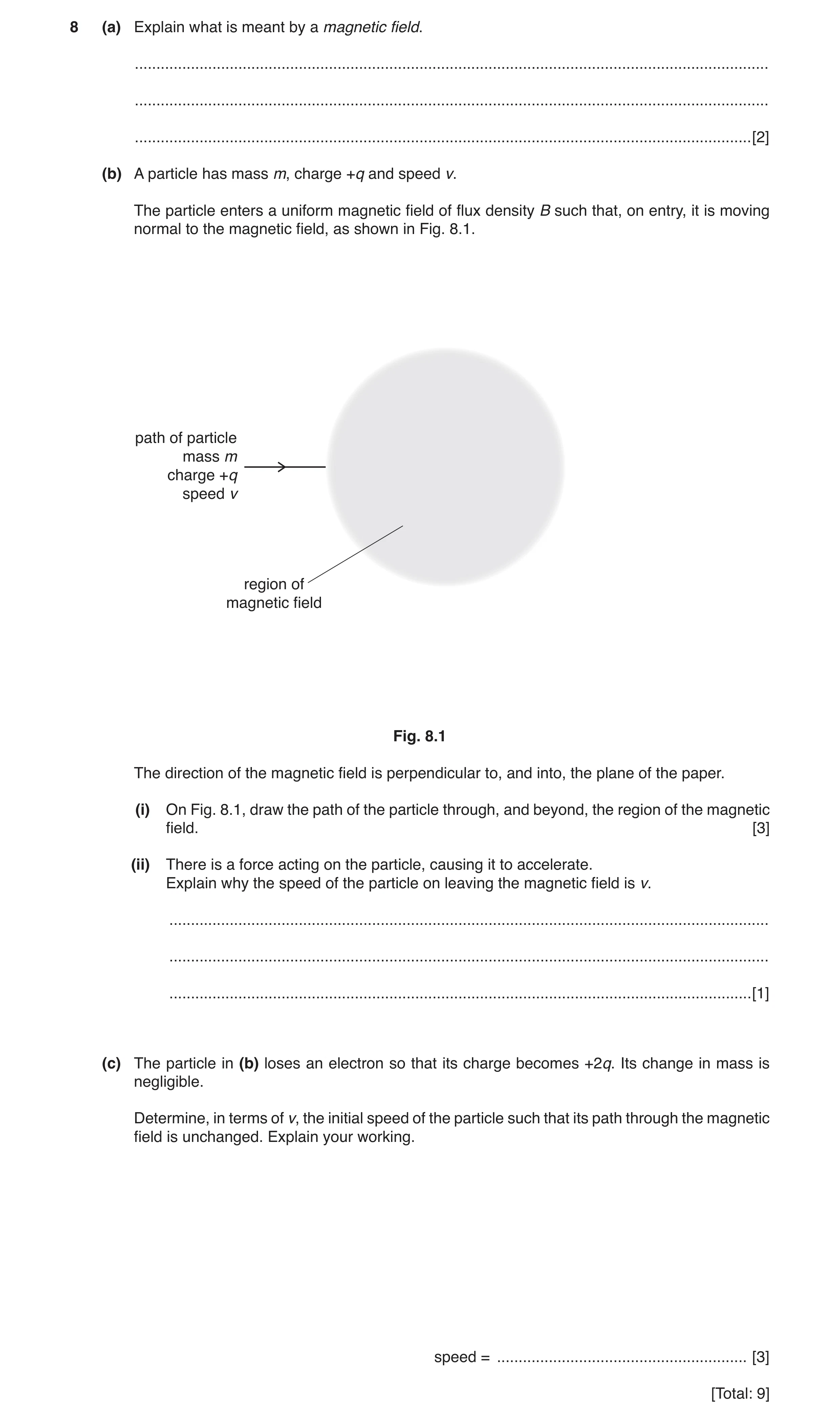
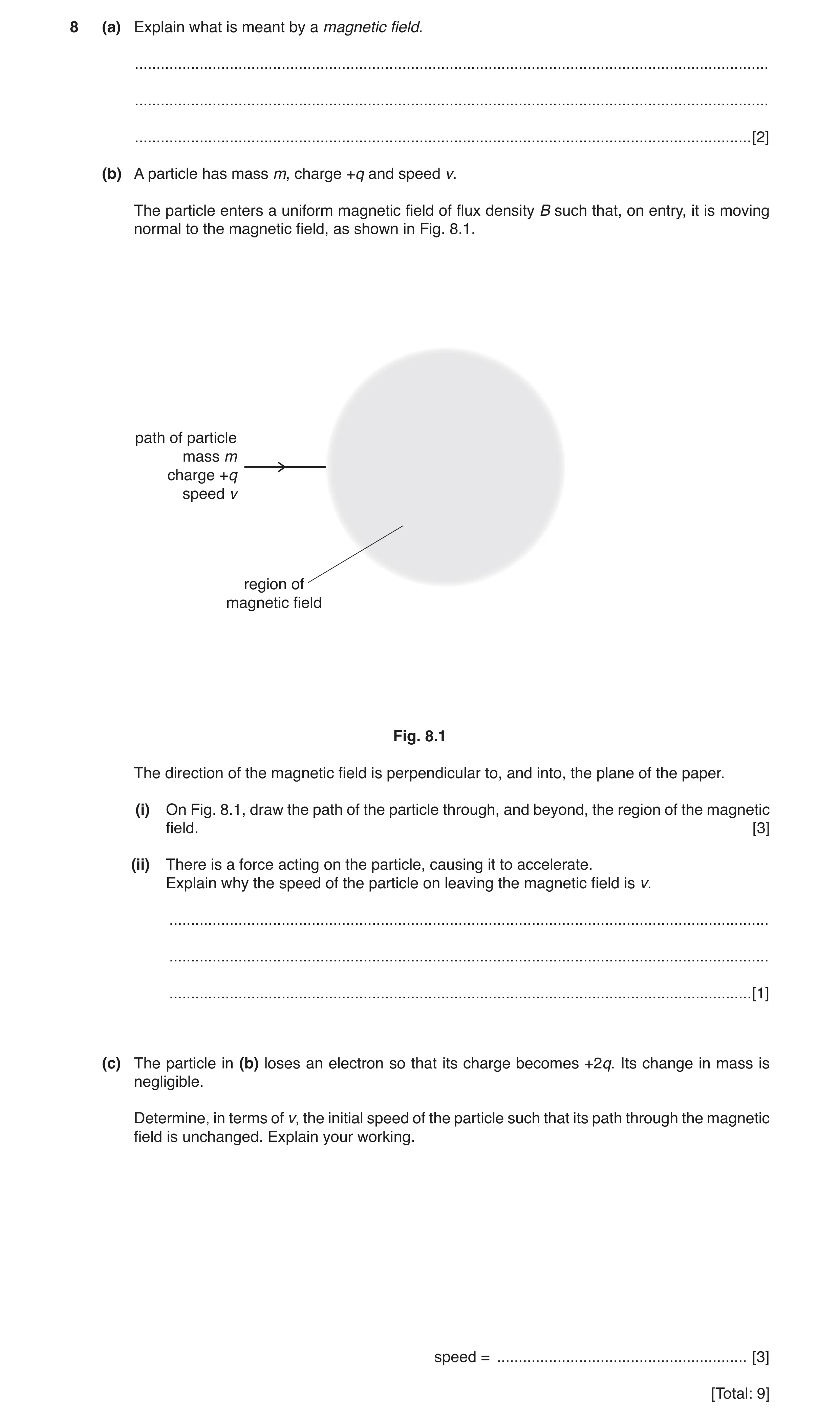
8 (a) Explain what is meant by a magnetic field. … … … [2] (b) A particle has mass m, charge +q and speed v. The particle enters a uniform magnetic field of flux density B such that, on entry, it is moving normal to the magnetic field, as shown in Fig. 8.1. path of particle mass m charge +q speed v region of magnetic field Fig. 8.1 The direction of the magnetic field is perpendicular to, and into, the plane of the paper. (i) On Fig. 8.1, draw the path of the particle through, and beyond, the region of the magnetic field. [3] (ii) There is a force acting on the particle, causing it to accelerate. Explain why the speed of the particle on leaving the magnetic field is v. … … … [1] (c) The particle in (b) loses an electron so that its charge becomes +2q. Its change in mass is negligible. Determine, in terms of v, the initial speed of the particle such that its path through the magnetic field is unchanged. Explain your working. speed = … [3] [Total: 9]
9 marks
Mark scheme: 8(a) region where there is a force M1 experienced by a current-carrying conductor/moving charge/(permanent) magnet A1 8(b)(i) single path, deflection in ‘upward’ direction B1 acceptable circular arc in whole field B1 no ‘kinks’ at start or end of curvature, and straight outside region of field B1 8(b)(ii) force (on particle) is normal to velocity/direction of motion/direction of speed B1 8(c) magnetic force provides/is the centripetal force B1 Bqv = mv2 / r or r = mv / Bq C1 (if q is doubled), new speed = 2v A1
This question in 9702/41 Oct/Nov 2018
Q3 · Define magnetic flux density 9702/42 Oct/Nov 2018
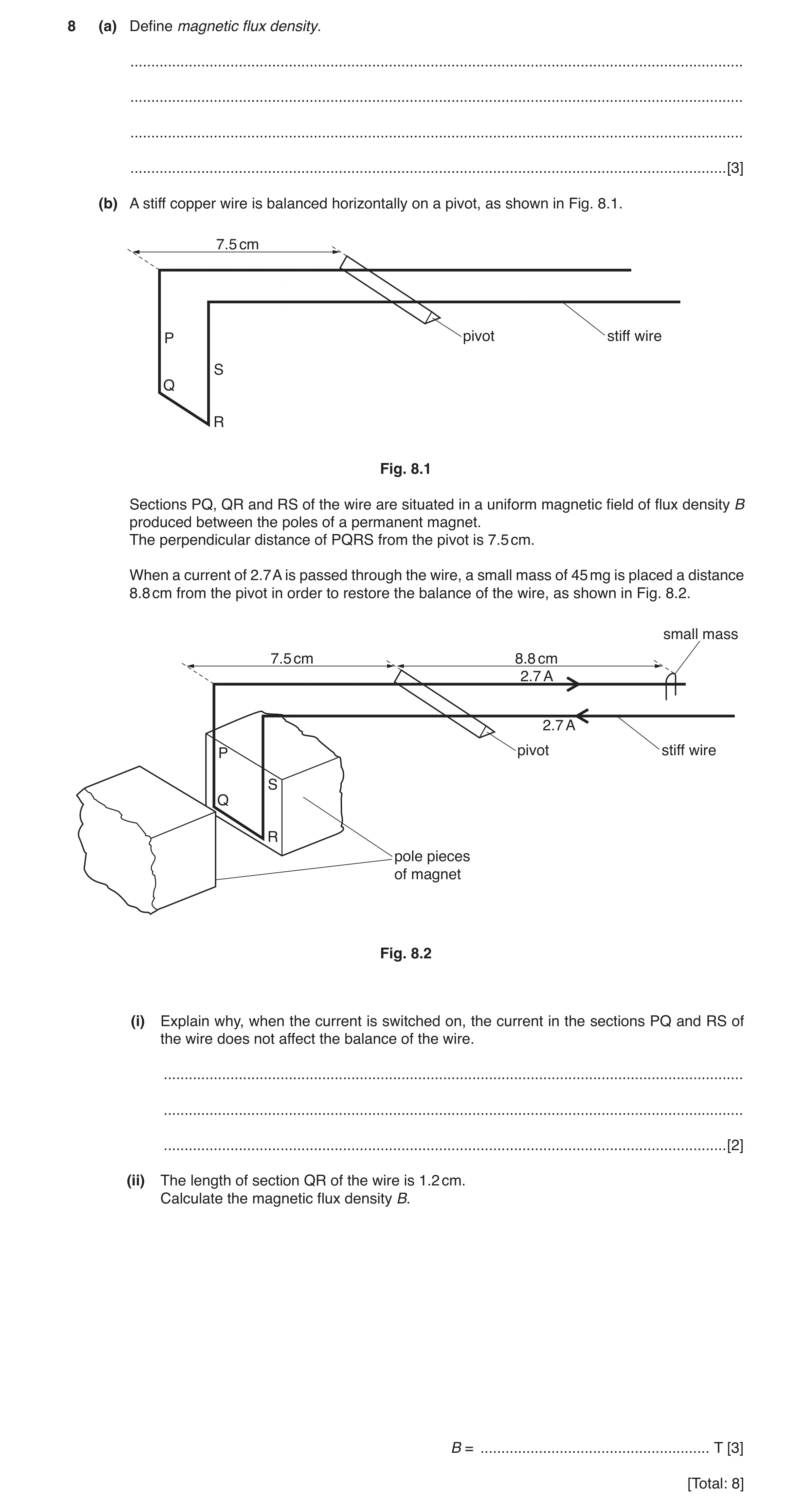
8 (a) Define magnetic flux density. … … … … [3] (b) A stiff copper wire is balanced horizontally on a pivot, as shown in Fig. 8.1. 7.5 cm P pivot stiff wire S Q R Fig. 8.1 Sections PQ, QR and RS of the wire are situated in a uniform magnetic field of flux density B produced between the poles of a permanent magnet. The perpendicular distance of PQRS from the pivot is 7.5 cm. When a current of 2.7 A is passed through the wire, a small mass of 45 mg is placed a distance 8.8 cm from the pivot in order to restore the balance of the wire, as shown in Fig. 8.2. small mass 7.5 cm 8.8 cm 2.7 A 2.7 A P pivot stiff wire S Q R pole pieces of magnet Fig. 8.2 (i) Explain why, when the current is switched on, the current in the sections PQ and RS of the wire does not affect the balance of the wire. … … … [2] (ii) The length of section QR of the wire is 1.2 cm. Calculate the magnetic flux density B. B = … T [3] [Total: 8]
8 marks
Mark scheme: 8(a) force per unit current B1 force per unit length (of wire) B1 current normal to (magnetic) field B1 8(b)(i) forces (on PQ and RS) are horizontal B1 (hence they create) no moment about the pivot B1 or forces (on PQ and RS) are equal and opposite (B1) (hence there is) no net force (on the two sections) (B1) 8(b)(ii) realisation of the need to apply moments C1 BILx = mgy B × 2.7 × 1.2 × 10–2 × 7.5 = 45 × 10–6 × 9.81 × 8.8 C1 B = 1.6 × 10⁻² T A1
This question in 9702/42 Oct/Nov 2018
Q4 · A Hall probe is placed near one end of a solenoid that has been wound on a soft-iron… 9702/42 Oct/Nov 2018
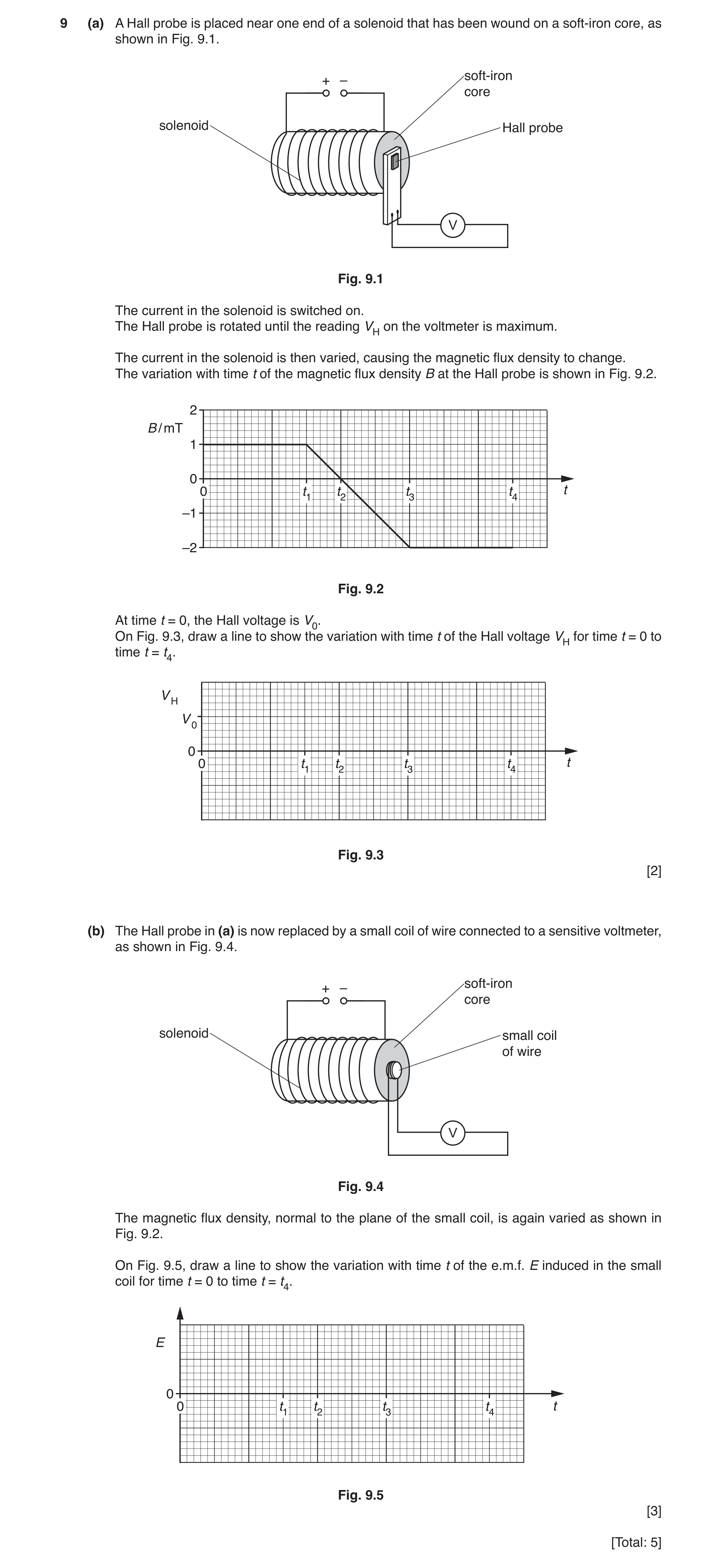
9 (a) A Hall probe is placed near one end of a solenoid that has been wound on a soft-iron core, as shown in Fig. 9.1. soft-iron + – core solenoid Hall probe V Fig. 9.1 The current in the solenoid is switched on. The Hall probe is rotated until the reading VH on the voltmeter is maximum. The current in the solenoid is then varied, causing the magnetic flux density to change. The variation with time t of the magnetic flux density B at the Hall probe is shown in Fig. 9.2. 2 B / mT 1 0 0 t1 t2 t3 t4 t –1 –2 Fig. 9.2 At time t = 0, the Hall voltage is V0. On Fig. 9.3, draw a line to show the variation with time t of the Hall voltage VH for time t = 0 to time t = t4. V H V 0 0 0 t1 t2 t3 t4 t Fig. 9.3 [2] (b) The Hall probe in (a) is now replaced by a small coil of wire connected to a sensitive voltmeter, as shown in Fig. 9.4. soft-iron + – core solenoid small coil of wire V Fig. 9.4 The magnetic flux density, normal to the plane of the small coil, is again varied as shown in Fig. 9.2. On Fig. 9.5, draw a line to show the variation with time t of the e.m.f. E induced in the small coil for time t = 0 to time t = t4. E 0 0 t1 t2 t3 t4 t Fig. 9.5 [3] [Total: 5]
5 marks
Mark scheme: 9(a) and t3 → t4 horizontal straight line at different non-zero VH B1 t1 → t3 straight diagonal line with negative gradient and graph line starts at (0, V0) and ends at (t4, –2V0) B1 9(b) E = 0 for 0 → t1 and t3 → t4 B1 E is non-zero at all points between t1 → t3 M1 E has constant magnitude between t1 → t3 A1
This question in 9702/42 Oct/Nov 2018
Q5 · Explain what is meant by a magnetic field 9702/43 Oct/Nov 2018
8 (a) Explain what is meant by a magnetic field. … … … [2] (b) A particle has mass m, charge +q and speed v. The particle enters a uniform magnetic field of flux density B such that, on entry, it is moving normal to the magnetic field, as shown in Fig. 8.1. path of particle mass m charge +q speed v region of magnetic field Fig. 8.1 The direction of the magnetic field is perpendicular to, and into, the plane of the paper. (i) On Fig. 8.1, draw the path of the particle through, and beyond, the region of the magnetic field. [3] (ii) There is a force acting on the particle, causing it to accelerate. Explain why the speed of the particle on leaving the magnetic field is v. … … … [1] (c) The particle in (b) loses an electron so that its charge becomes +2q. Its change in mass is negligible. Determine, in terms of v, the initial speed of the particle such that its path through the magnetic field is unchanged. Explain your working. speed = … [3] [Total: 9]
9 marks
Mark scheme: 8(a) region where there is a force M1 experienced by a current-carrying conductor/moving charge/(permanent) magnet A1 8(b)(i) single path, deflection in ‘upward’ direction B1 acceptable circular arc in whole field B1 no ‘kinks’ at start or end of curvature, and straight outside region of field B1 8(b)(ii) force (on particle) is normal to velocity/direction of motion/direction of speed B1 8(c) magnetic force provides/is the centripetal force B1 Bqv = mv2 / r or r = mv / Bq C1 (if q is doubled), new speed = 2v A1
This question in 9702/43 Oct/Nov 2018
Q6 · A solenoid is connected in series with a battery and a switch, as illustrated in Fig 9702/41 May/June 2019
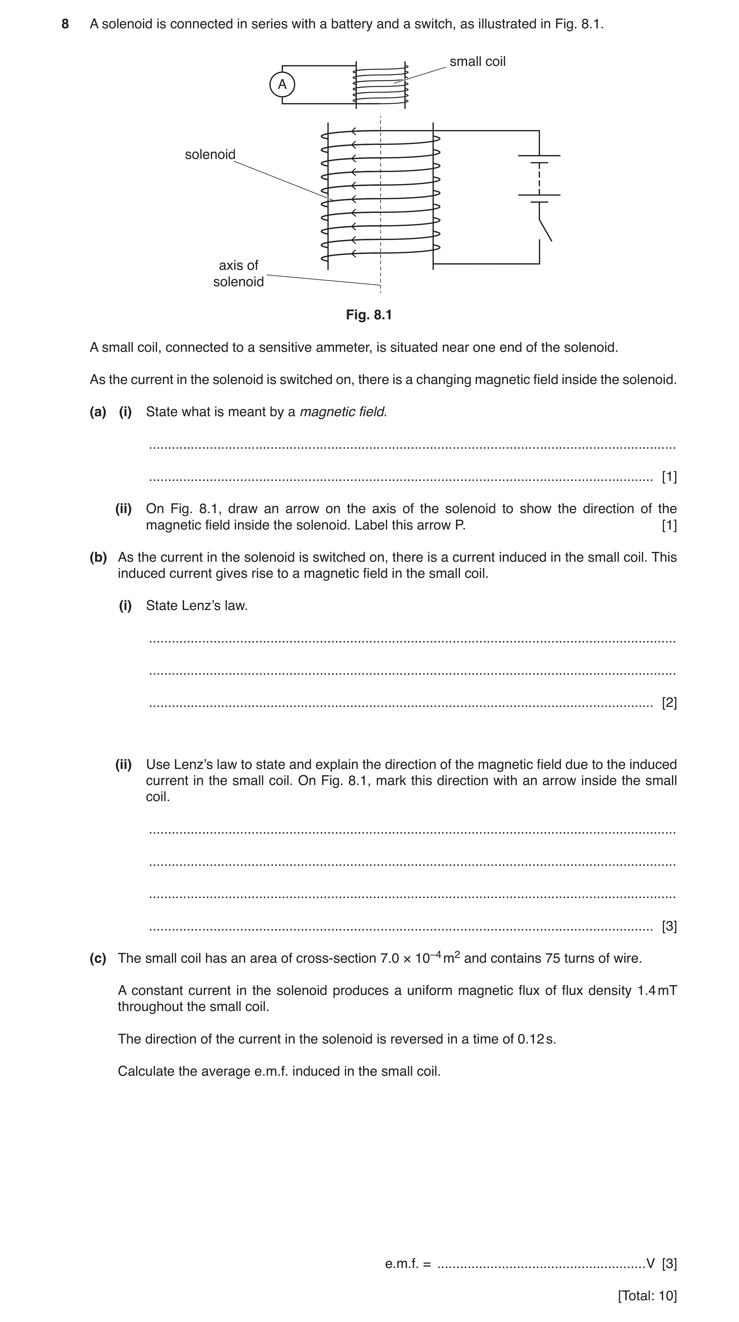
8 A solenoid is connected in series with a battery and a switch, as illustrated in Fig. 8.1. small coil A solenoid axis of solenoid Fig. 8.1 A small coil, connected to a sensitive ammeter, is situated near one end of the solenoid. As the current in the solenoid is switched on, there is a changing magnetic field inside the solenoid. (a) (i) State what is meant by a magnetic field. … … [1] (ii) On Fig. 8.1, draw an arrow on the axis of the solenoid to show the direction of the magnetic field inside the solenoid. Label this arrow P. [1] (b) As the current in the solenoid is switched on, there is a current induced in the small coil. This induced current gives rise to a magnetic field in the small coil. (i) State Lenz’s law. … … … [2] (ii) Use Lenz’s law to state and explain the direction of the magnetic field due to the induced current in the small coil. On Fig. 8.1, mark this direction with an arrow inside the small coil. … … … … [3] (c) The small coil has an area of cross-section 7.0 × 10⁻⁴ m2 and contains 75 turns of wire. A constant current in the solenoid produces a uniform magnetic flux of flux density 1.4 mT throughout the small coil. The direction of the current in the solenoid is reversed in a time of 0.12 s. Calculate the average e.m.f. induced in the small coil. e.m.f. = … V [3] [Total: 10]
10 marks
Mark scheme: 8(a)(i) region where a force is exerted on: a magnetic pole or a moving charge or a current-carrying wire B1 8(a)(ii) arrow on axis of solenoid pointing downwards labelled P B1 8(b)(i) direction of induced e.m.f./current M1 (tends to) oppose the change causing it A1 8(b)(ii) magnetic field in solenoid is increasing B1 field in coil in opposite direction to oppose increase B1 arrow inside or just above small coil pointing in opposite direction to P B1 8(c) e.m.f. = N∆φ / ∆t C1 = (75 × 1.4 × 10–3 × 2 × 7.0 × 10–4) / 0.12 C1 = 1.2 × 10⁻³ V A1
This question in 9702/41 May/June 2019
Q7 · Nuclear magnetic resonance imaging (NMRI) is used to obtain diagnostic information about… 9702/41 May/June 2019
9 Nuclear magnetic resonance imaging (NMRI) is used to obtain diagnostic information about internal body structures. State, during the use of NMRI, the function of: (a) the large constant magnetic field … … … … … [3] (b) the non-uniform magnetic field. … … … … … [2] [Total: 5]
5 marks
Mark scheme: 9(a) nuclei precess B1 precession is about direction of magnetic field B1 frequency of precession depends on field strength or frequency of precession is in radio-frequency range B1 9(b) Any two points from: • frequency (of precession) depends on position • to locate position of (spinning) nuclei • to change region where nuclei are detected B2
This question in 9702/41 May/June 2019
Q8 · A solenoid is connected in series with a battery and a switch, as illustrated in Fig 9702/43 May/June 2019
8 A solenoid is connected in series with a battery and a switch, as illustrated in Fig. 8.1. small coil A solenoid axis of solenoid Fig. 8.1 A small coil, connected to a sensitive ammeter, is situated near one end of the solenoid. As the current in the solenoid is switched on, there is a changing magnetic field inside the solenoid. (a) (i) State what is meant by a magnetic field. … … [1] (ii) On Fig. 8.1, draw an arrow on the axis of the solenoid to show the direction of the magnetic field inside the solenoid. Label this arrow P. [1] (b) As the current in the solenoid is switched on, there is a current induced in the small coil. This induced current gives rise to a magnetic field in the small coil. (i) State Lenz’s law. … … … [2] (ii) Use Lenz’s law to state and explain the direction of the magnetic field due to the induced current in the small coil. On Fig. 8.1, mark this direction with an arrow inside the small coil. … … … … [3] (c) The small coil has an area of cross-section 7.0 × 10⁻⁴ m2 and contains 75 turns of wire. A constant current in the solenoid produces a uniform magnetic flux of flux density 1.4 mT throughout the small coil. The direction of the current in the solenoid is reversed in a time of 0.12 s. Calculate the average e.m.f. induced in the small coil. e.m.f. = … V [3] [Total: 10]
10 marks
Mark scheme: 8(a)(i) region where a force is exerted on: a magnetic pole or a moving charge or a current-carrying wire B1 8(a)(ii) arrow on axis of solenoid pointing downwards labelled P B1 8(b)(i) direction of induced e.m.f./current M1 (tends to) oppose the change causing it A1 8(b)(ii) magnetic field in solenoid is increasing B1 field in coil in opposite direction to oppose increase B1 arrow inside or just above small coil pointing in opposite direction to P B1 8(c) e.m.f. = N∆φ / ∆t C1 = (75 × 1.4 × 10–3 × 2 × 7.0 × 10–4) / 0.12 C1 = 1.2 × 10⁻³ V A1
This question in 9702/43 May/June 2019
Q9 · Nuclear magnetic resonance imaging (NMRI) is used to obtain diagnostic information about… 9702/43 May/June 2019
9 Nuclear magnetic resonance imaging (NMRI) is used to obtain diagnostic information about internal body structures. State, during the use of NMRI, the function of: (a) the large constant magnetic field … … … … … [3] (b) the non-uniform magnetic field. … … … … … [2] [Total: 5]
5 marks
Mark scheme: 9(a) nuclei precess B1 precession is about direction of magnetic field B1 frequency of precession depends on field strength or frequency of precession is in radio-frequency range B1 9(b) Any two points from: • frequency (of precession) depends on position • to locate position of (spinning) nuclei • to change region where nuclei are detected B2
This question in 9702/43 May/June 2019
Q10 · Diagnosis using nuclear magnetic resonance imaging (NMRI) requires the use of a… 9702/41 Oct/Nov 2019
9 Diagnosis using nuclear magnetic resonance imaging (NMRI) requires the use of a non-uniform magnetic field superimposed on a constant magnetic field of large magnitude. Explain the purpose of: (a) the large constant magnetic field … … … … … [2] (b) the non-uniform magnetic field. … … … … … [2] [Total: 4]
4 marks
Mark scheme: 9(a) nuclei precess B1 precession is about (direction of magnetic) field or frequency of precession is in radio-frequency range B1 9(b) • frequency (of precession) depends on field strength • to locate/find position of (spinning) nuclei • to change region where nuclei are detected any two points, one mark each B2
This question in 9702/41 Oct/Nov 2019
Q11 · Diagnosis using nuclear magnetic resonance imaging (NMRI) requires the use of a… 9702/43 Oct/Nov 2019
9 Diagnosis using nuclear magnetic resonance imaging (NMRI) requires the use of a non-uniform magnetic field superimposed on a constant magnetic field of large magnitude. Explain the purpose of: (a) the large constant magnetic field … … … … … [2] (b) the non-uniform magnetic field. … … … … … [2] [Total: 4]
4 marks
Mark scheme: 9(a) nuclei precess B1 precession is about (direction of magnetic) field or frequency of precession is in radio-frequency range B1 9(b) • frequency (of precession) depends on field strength • to locate/find position of (spinning) nuclei • to change region where nuclei are detected any two points, one mark each B2
This question in 9702/43 Oct/Nov 2019
Q12 · Explain what is meant by a magnetic field 9702/42 Feb/March 2020
8 (a) Explain what is meant by a magnetic field. … … … … [1] (b) The apparatus shown in Fig. 8.1 is used in an experiment to find the magnetic flux density B between the poles of a horseshoe magnet. Assume the magnetic field is uniform between the poles of the magnet and zero elsewhere. 45 mm horseshoe magnet 300 mm metal rod balance pan Fig. 8.1 The rigid metal rod of length 300 mm is fixed in position perpendicular to the direction of the magnetic field. The poles of the magnet are both 45 mm long. There is a current in the rod that causes a force on the rod. The balance is used to determine the magnitude of the force. The variation with current I of the force F on the rod is shown in Fig. 8.2. 10.0 8.0 F / mN 6.0 4.0 2.0 0 0 1.0 2.0 3.0 4.0 5.0 I / A Fig. 8.2 Calculate the magnetic flux density B. B = … T [2] (c) In a different experiment, electrons are accelerated through a potential difference and then enter a region of magnetic field. The magnetic field is into the plane of the paper and is perpendicular to the direction of travel of the electrons, as illustrated in Fig. 8.3. region of magnetic field into the plane of the paper electron beam Fig. 8.3 (i) Explain why the electrons follow a circular path when inside the region of the magnetic field. … … … … [3] (ii) State the measurements needed in order to determine the charge to mass ratio, e /me, of an electron. … … … [2] [Total: 8]
8 marks
Mark scheme: 8(a) a region where a magnet / magnetic material / moving charge / current carrying conductor experiences a force B1 8(b) B = F / Il e.g. = 9 × 10⁻³ / (5.0 × 0.045) C1 = 0.040 T A1 8(c)(i) force is (always) perpendicular to the velocity / direction of motion B1 magnetic force provides the centripetal force or force perpendicular to motion causes circular motion B1 magnitude of force (due to the magnetic field) is constant or no work done by force or the force does not change the speed B1 8(c)(ii) Applying the list rule, any 2 from: accelerating p.d. radius of path / radius of semicircle magnetic flux density B2
This question in 9702/42 Feb/March 2020
Question 13 9702/41 May/June 2020
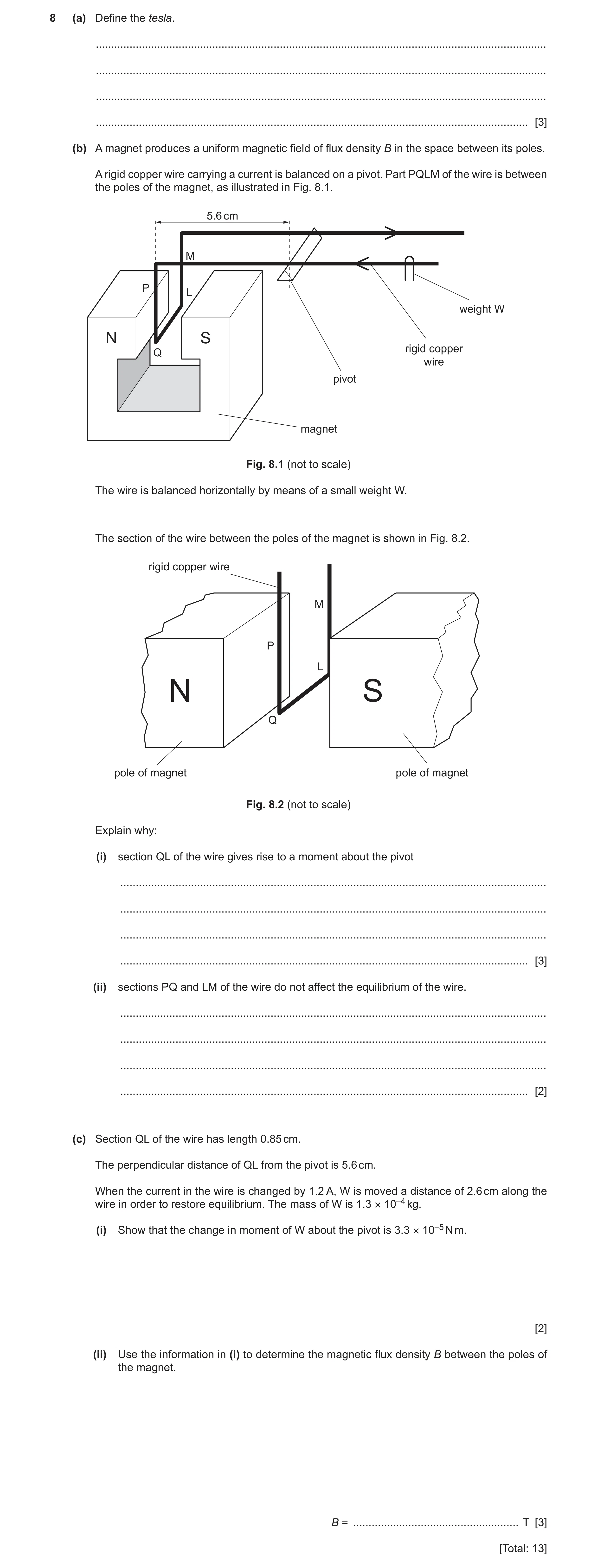
8 (a) Define the tesla. … … … … [3] (b) A magnet produces a uniform magnetic field of flux density B in the space between its poles. A rigid copper wire carrying a current is balanced on a pivot. Part PQLM of the wire is between the poles of the magnet, as illustrated in Fig. 8.1. 5.6 cm M P L weight W N S rigid copper Q wire pivot magnet Fig. 8.1 (not to scale) The wire is balanced horizontally by means of a small weight W. The section of the wire between the poles of the magnet is shown in Fig. 8.2. rigid copper wire M P L N S Q pole of magnet pole of magnet Fig. 8.2 (not to scale) Explain why: (i) section QL of the wire gives rise to a moment about the pivot … … … … [3] (ii) sections PQ and LM of the wire do not affect the equilibrium of the wire. … … … … [2] (c) Section QL of the wire has length 0.85 cm. The perpendicular distance of QL from the pivot is 5.6 cm. When the current in the wire is changed by 1.2 A, W is moved a distance of 2.6 cm along the wire in order to restore equilibrium. The mass of W is 1.3 × 10⁻⁴ kg. (i) Show that the change in moment of W about the pivot is 3.3 × 10⁻⁵ N m. [2] (ii) Use the information in (i) to determine the magnetic flux density B between the poles of the magnet. B = … T [3] [Total: 13]
13 marks
Mark scheme: 8(a) magnetic field normal to current B1 newton per ampere B1 newton per metre B1 8(b)(i) current in wire QL gives rise to a force or wire QL is perpendicular to the magnetic field B1 force on wire QL is vertical B1 force does not act through the pivot B1 8(b)(ii) forces act through the same line or forces are horizontal B1 forces are equal (in magnitude) and opposite (in direction) B1 8(c)(i) change = mg × (Δ)L C1 = 1.3 × 10–4 × 9.81 × 2.6 × 10–2 = 3.3 × 10⁻⁵ N m–1 A1 8(c)(ii) change = B × (Δ)I × L × x C1 3.3 × 10–5 = B × 1.2 × 0.85 × 10–2 × 5.6 × 10–2 C1 B = 0.058 T A1
This question in 9702/41 May/June 2020
Question 14 9702/43 May/June 2020
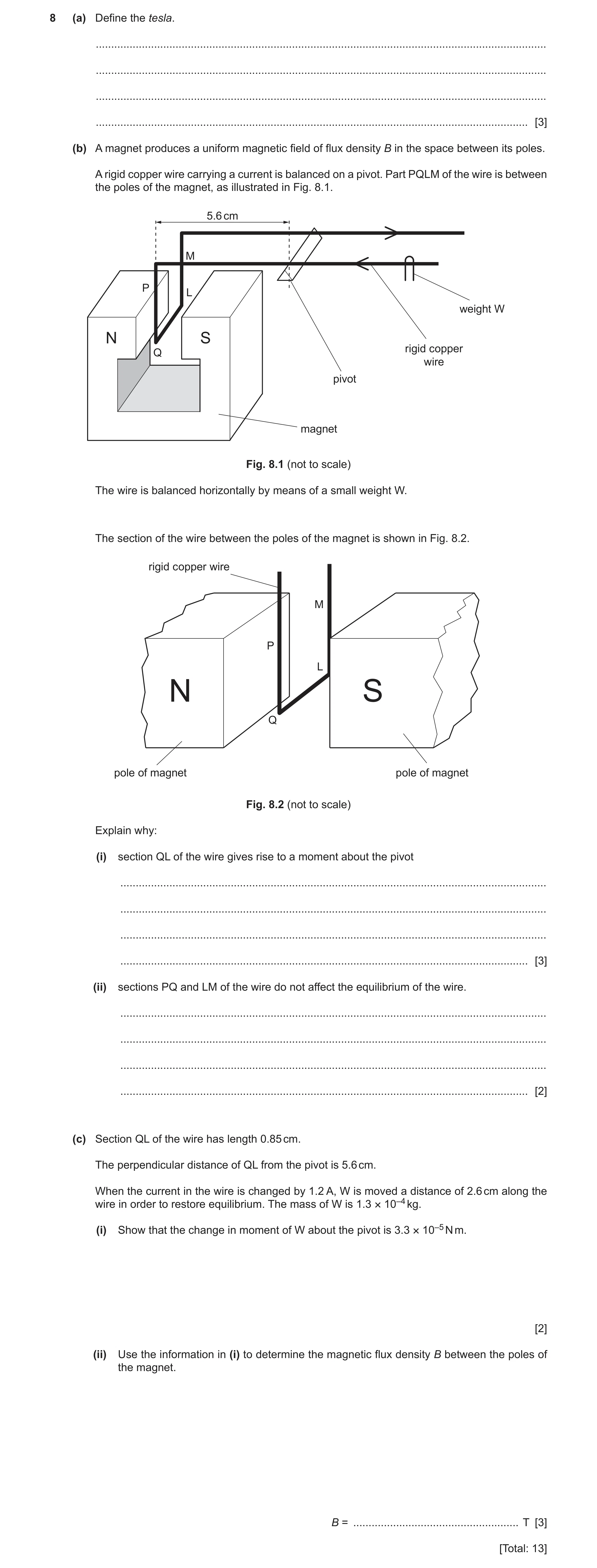
8 (a) Define the tesla. … … … … [3] (b) A magnet produces a uniform magnetic field of flux density B in the space between its poles. A rigid copper wire carrying a current is balanced on a pivot. Part PQLM of the wire is between the poles of the magnet, as illustrated in Fig. 8.1. 5.6 cm M P L weight W N S rigid copper Q wire pivot magnet Fig. 8.1 (not to scale) The wire is balanced horizontally by means of a small weight W. The section of the wire between the poles of the magnet is shown in Fig. 8.2. rigid copper wire M P L N S Q pole of magnet pole of magnet Fig. 8.2 (not to scale) Explain why: (i) section QL of the wire gives rise to a moment about the pivot … … … … [3] (ii) sections PQ and LM of the wire do not affect the equilibrium of the wire. … … … … [2] (c) Section QL of the wire has length 0.85 cm. The perpendicular distance of QL from the pivot is 5.6 cm. When the current in the wire is changed by 1.2 A, W is moved a distance of 2.6 cm along the wire in order to restore equilibrium. The mass of W is 1.3 × 10⁻⁴ kg. (i) Show that the change in moment of W about the pivot is 3.3 × 10⁻⁵ N m. [2] (ii) Use the information in (i) to determine the magnetic flux density B between the poles of the magnet. B = … T [3] [Total: 13]
13 marks
Mark scheme: 8(a) magnetic field normal to current B1 newton per ampere B1 newton per metre B1 8(b)(i) current in wire QL gives rise to a force or wire QL is perpendicular to the magnetic field B1 force on wire QL is vertical B1 force does not act through the pivot B1 8(b)(ii) forces act through the same line or forces are horizontal B1 forces are equal (in magnitude) and opposite (in direction) B1 8(c)(i) change = mg × (Δ)L C1 = 1.3 × 10–4 × 9.81 × 2.6 × 10–2 = 3.3 × 10⁻⁵ N m–1 A1 8(c)(ii) change = B × (Δ)I × L × x C1 3.3 × 10–5 = B × 1.2 × 0.85 × 10–2 × 5.6 × 10–2 C1 B = 0.058 T A1
This question in 9702/43 May/June 2020
Q15 · A small coil is placed close to one end of a solenoid connected to a power supply 9702/42 Oct/Nov 2020
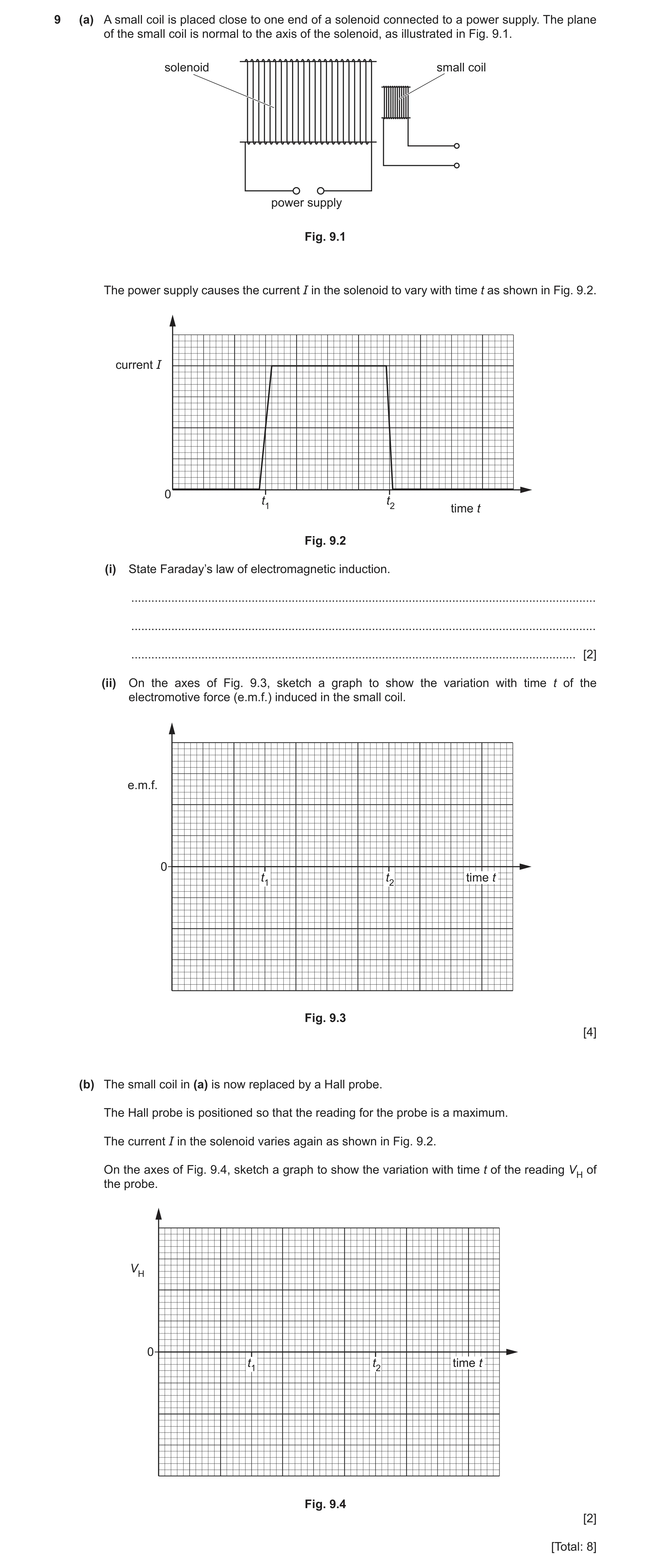
9 (a) A small coil is placed close to one end of a solenoid connected to a power supply. The plane of the small coil is normal to the axis of the solenoid, as illustrated in Fig. 9.1. solenoid small coil power supply Fig. 9.1 The power supply causes the current I in the solenoid to vary with time t as shown in Fig. 9.2. current I 0 t1 t2 time t Fig. 9.2 (i) State Faraday’s law of electromagnetic induction. … … … [2] (ii) On the axes of Fig. 9.3, sketch a graph to show the variation with time t of the electromotive force (e.m.f.) induced in the small coil. e.m.f. 0 t1 t2 time t Fig. 9.3 [4] (b) The small coil in (a) is now replaced by a Hall probe. The Hall probe is positioned so that the reading for the probe is a maximum. The current I in the solenoid varies again as shown in Fig. 9.2. On the axes of Fig. 9.4, sketch a graph to show the variation with time t of the reading VH of the probe. VH 0 t1 t2 time t Fig. 9.4 [2] [Total: 8]
8 marks
Mark scheme: 9(a)(i) (induced) e.m.f. (directly) proportional to rate M1 of change of magnetic flux (linkage) A1 9(a)(ii) e.m.f. = 0 apart from thin pulses at t1 and t2 B1 rectangular pulses centred on t1 and t2, of widths 2 small squares and 1 small square respectively B1 e.m.fs. at t1 and t2 have opposite polarities B1 magnitude of e.m.f. at t2 double the magnitude of e.m.f. at t1 B1 9(b) VH shown as zero before (t1 – 2 squares) and after (t2 + 2 squares) and rises to a constant non-zero value between t1 and t2 M1 change at t1 shown as 2 small squares wide and change at t2 shown as 1 small square wide A1
This question in 9702/42 Oct/Nov 2020
Q16 · State what is meant by a magnetic field 9702/41 May/June 2021
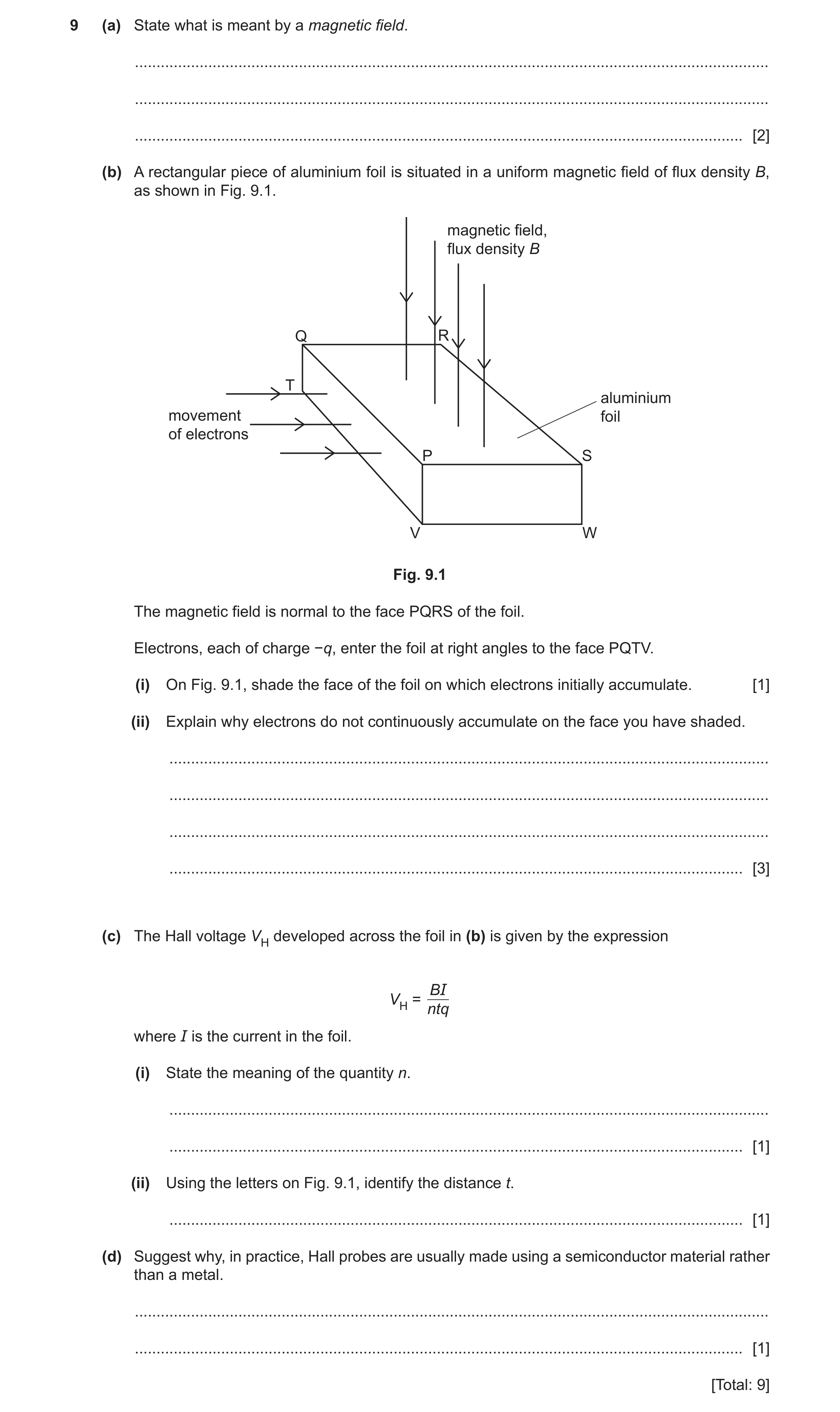
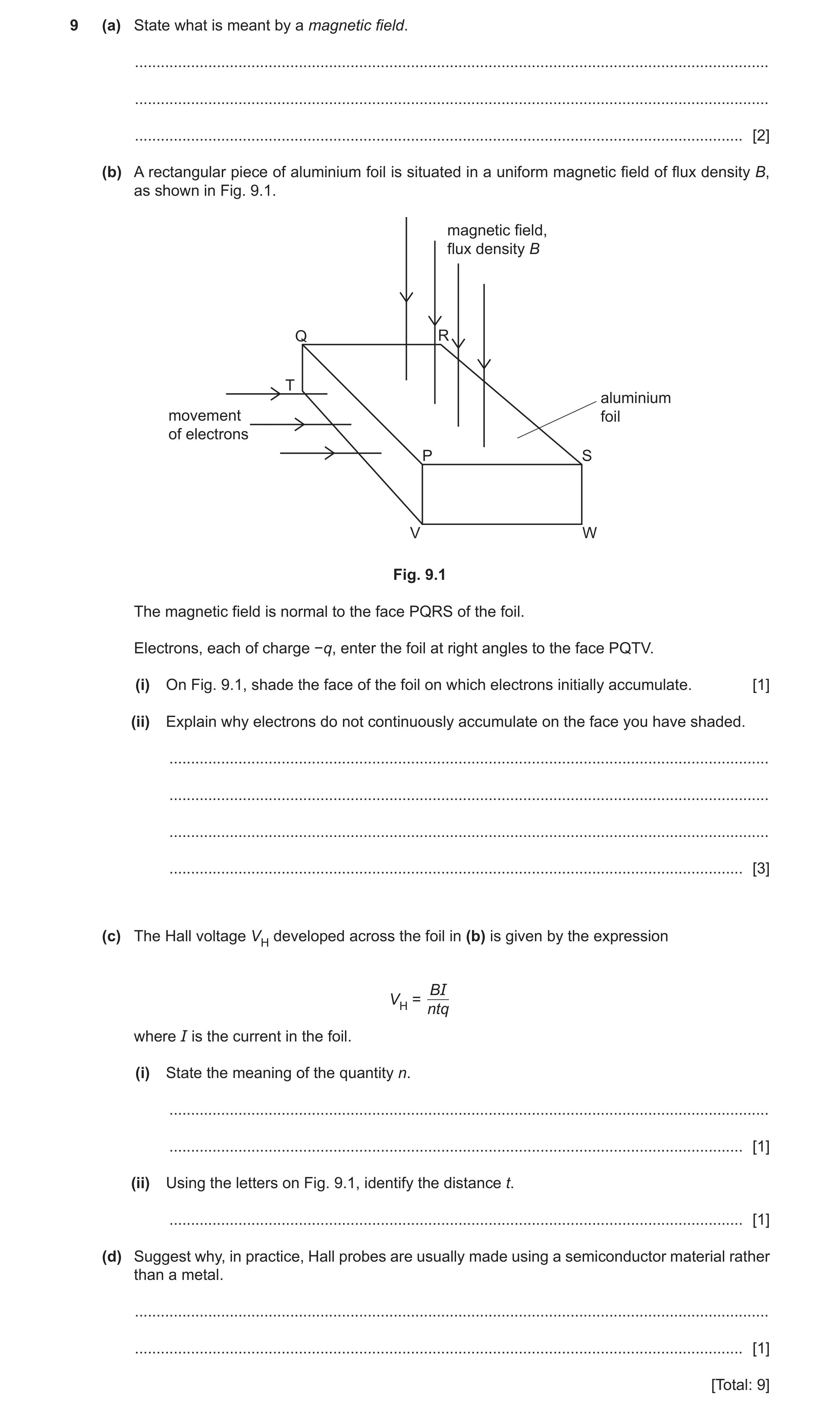
9 (a) State what is meant by a magnetic field. … … … [2] (b) A rectangular piece of aluminium foil is situated in a uniform magnetic field of flux density B, as shown in Fig. 9.1. magnetic field, flux density B Q R T aluminium movement foil of electrons P S V W Fig. 9.1 The magnetic field is normal to the face PQRS of the foil. Electrons, each of charge −q, enter the foil at right angles to the face PQTV. (i) On Fig. 9.1, shade the face of the foil on which electrons initially accumulate. [1] (ii) Explain why electrons do not continuously accumulate on the face you have shaded. … … … … [3] (c) The Hall voltage VH developed across the foil in (b) is given by the expression BI VH = ntq where I is the current in the foil. (i) State the meaning of the quantity n. … … [1] (ii) Using the letters on Fig. 9.1, identify the distance t. … [1] (d) Suggest why, in practice, Hall probes are usually made using a semiconductor material rather than a metal. … … [1] [Total: 9]
9 marks
Mark scheme: 9(a) region where there is a force exerted on M1 a current-carrying conductor or a moving charge or a magnetic material/magnetic pole A1 9(b)(i) face PSWV shaded B1 9(b)(ii) accumulating electrons cause an electric field (between the faces) B1 force due to electric field opposes force due to magnetic field B1 accumulation stops when magnetic force equals electric force B1 9(c)(i) number density of charge carriers B1 9(c)(ii) PV or QT or SW B1 9(d) (for semiconductor,) n is (much) smaller so VH (much) larger B1
This question in 9702/41 May/June 2021
Q17 · Define magnetic flux density 9702/42 May/June 2021
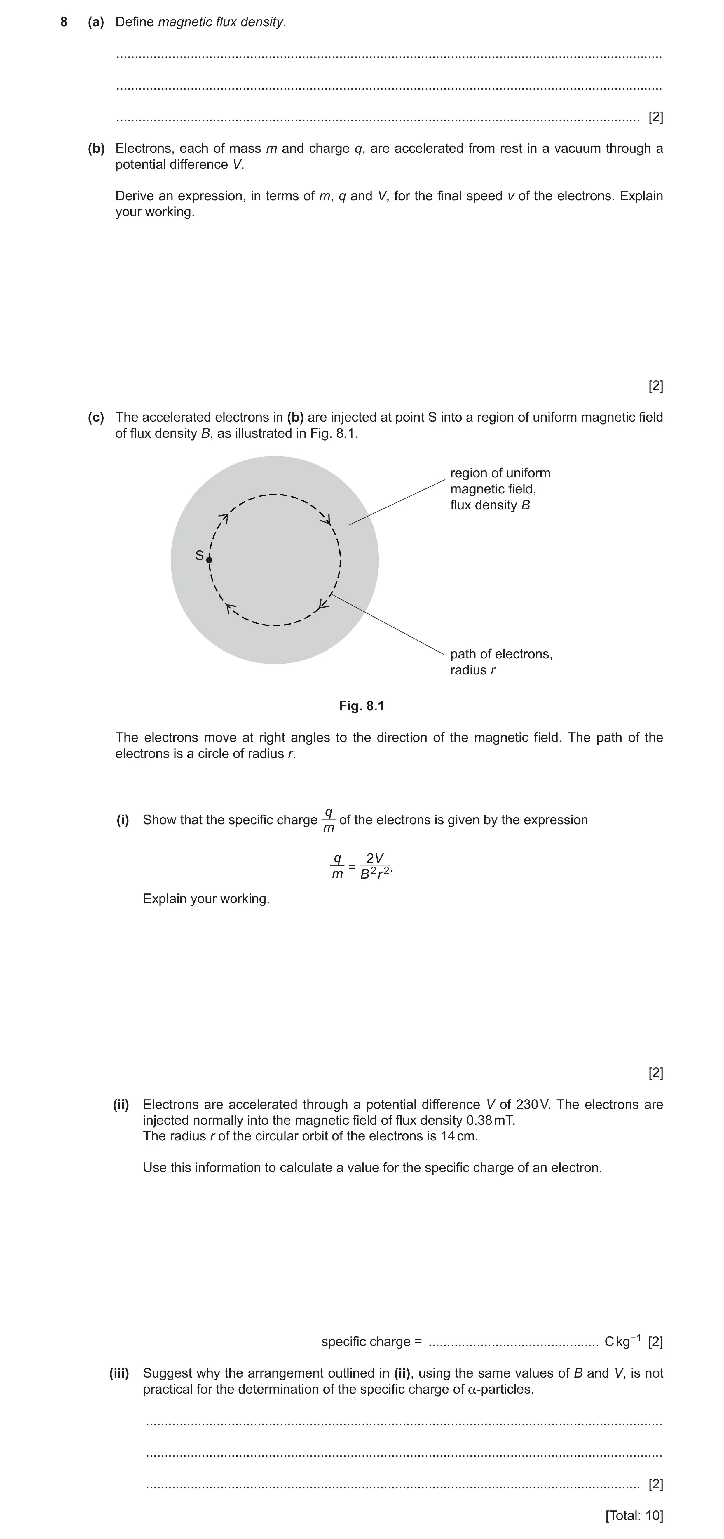
8 (a) Define magnetic flux density. … … … [2] (b) Electrons, each of mass m and charge q, are accelerated from rest in a vacuum through a potential difference V. Derive an expression, in terms of m, q and V, for the final speed v of the electrons. Explain your working. [2] (c) The accelerated electrons in (b) are injected at point S into a region of uniform magnetic field of flux density B, as illustrated in Fig. 8.1. region of uniform magnetic field, flux density B S path of electrons, radius r Fig. 8.1 The electrons move at right angles to the direction of the magnetic field. The path of the electrons is a circle of radius r. q (i) Show that the specific charge of the electrons is given by the expression m q 2V = 2 2. m B r Explain your working. [2] (ii) Electrons are accelerated through a potential difference V of 230 V. The electrons are injected normally into the magnetic field of flux density 0.38 mT. The radius r of the circular orbit of the electrons is 14 cm. Use this information to calculate a value for the specific charge of an electron. specific charge = … C kg−1 [2] (iii) Suggest why the arrangement outlined in (ii), using the same values of B and V, is not practical for the determination of the specific charge of α-particles. … … … [2] [Total: 10]
10 marks
Mark scheme: 8(a) • force per unit length • force per unit current • length/current perpendicular to field 1 mark for any two points, 2 marks for all three points B2 8(b) change in potential energy = change in kinetic energy or qV = ½mv2 B1 v = √(2qV / m) A1 8(c)(i) magnetic force = centripetal force or Bqv = mv2 / r M1 clear substitution of expression for v and correct algebra leading to q / m = 2V / B2r2 A1 8(c)(ii) q / m = (2 × 230) / [(0.38 × 10⁻³)2 × 0.142] C1 = 1.6 × 10¹¹ C kg–1 A1 8(c)(iii) (for α-particle,) q / m is (much) smaller B1 r would be much larger B1
This question in 9702/42 May/June 2021
Q18 · State what is meant by a magnetic field 9702/43 May/June 2021
9 (a) State what is meant by a magnetic field. … … … [2] (b) A rectangular piece of aluminium foil is situated in a uniform magnetic field of flux density B, as shown in Fig. 9.1. magnetic field, flux density B Q R T aluminium movement foil of electrons P S V W Fig. 9.1 The magnetic field is normal to the face PQRS of the foil. Electrons, each of charge −q, enter the foil at right angles to the face PQTV. (i) On Fig. 9.1, shade the face of the foil on which electrons initially accumulate. [1] (ii) Explain why electrons do not continuously accumulate on the face you have shaded. … … … … [3] (c) The Hall voltage VH developed across the foil in (b) is given by the expression BI VH = ntq where I is the current in the foil. (i) State the meaning of the quantity n. … … [1] (ii) Using the letters on Fig. 9.1, identify the distance t. … [1] (d) Suggest why, in practice, Hall probes are usually made using a semiconductor material rather than a metal. … … [1] [Total: 9]
9 marks
Mark scheme: 9(a) region where there is a force exerted on M1 a current-carrying conductor or a moving charge or a magnetic material/magnetic pole A1 9(b)(i) face PSWV shaded B1 9(b)(ii) accumulating electrons cause an electric field (between the faces) B1 force due to electric field opposes force due to magnetic field B1 accumulation stops when magnetic force equals electric force B1 9(c)(i) number density of charge carriers B1 9(c)(ii) PV or QT or SW B1 9(d) (for semiconductor,) n is (much) smaller so VH (much) larger B1
This question in 9702/43 May/June 2021
Question 19 9702/41 Oct/Nov 2021
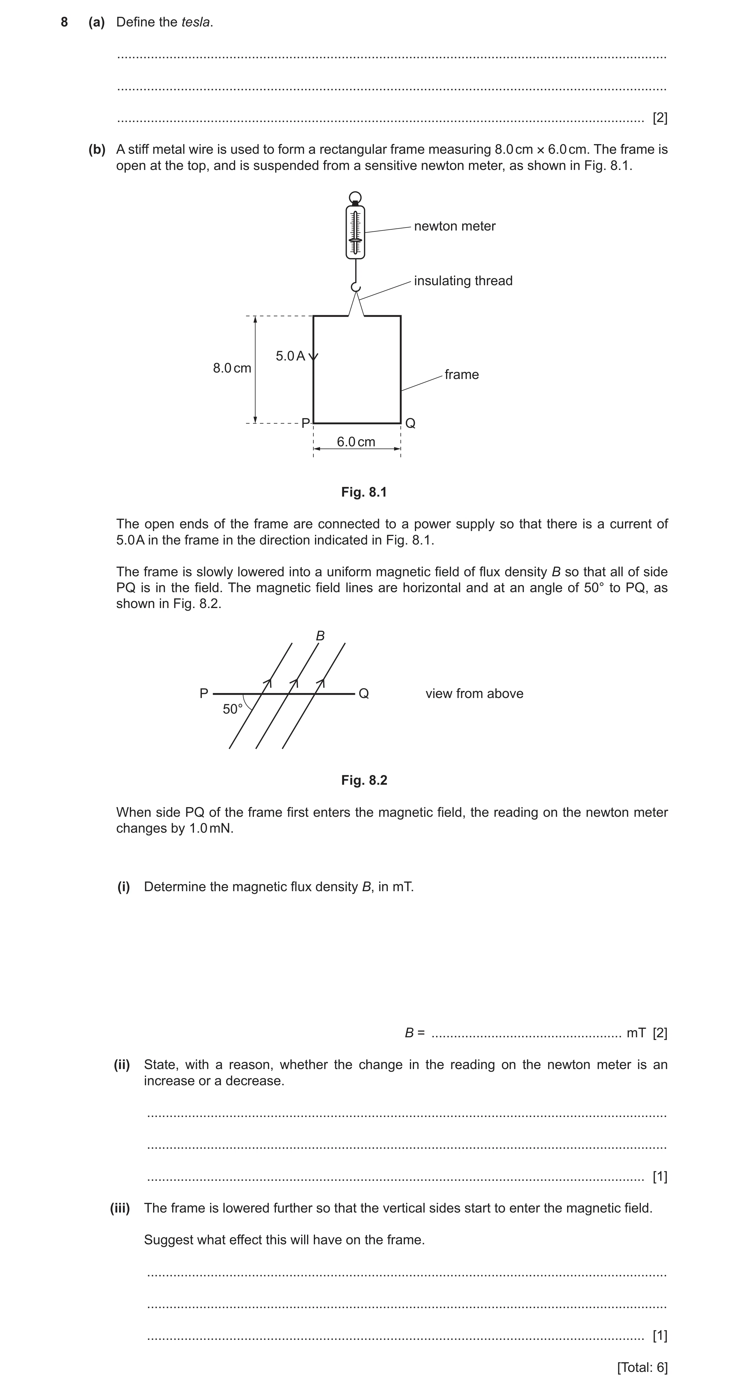
8 (a) Define the tesla. … … … [2] (b) A stiff metal wire is used to form a rectangular frame measuring 8.0 cm × 6.0 cm. The frame is open at the top, and is suspended from a sensitive newton meter, as shown in Fig. 8.1. newton meter insulating thread 5.0 A 8.0 cm frame P Q 6.0 cm Fig. 8.1 The open ends of the frame are connected to a power supply so that there is a current of 5.0 A in the frame in the direction indicated in Fig. 8.1. The frame is slowly lowered into a uniform magnetic field of flux density B so that all of side PQ is in the field. The magnetic field lines are horizontal and at an angle of 50° to PQ, as shown in Fig. 8.2. B P Q view from above 50° Fig. 8.2 When side PQ of the frame first enters the magnetic field, the reading on the newton meter changes by 1.0 mN. (i) Determine the magnetic flux density B, in mT. B = … mT [2] (ii) State, with a reason, whether the change in the reading on the newton meter is an increase or a decrease. … … … [1] (iii) The frame is lowered further so that the vertical sides start to enter the magnetic field. Suggest what effect this will have on the frame. … … … [1] [Total: 6]
6 marks
Mark scheme: 8(a) newton per ampere per metre M1 where current/wire is perpendicular to magnetic field A1 8(b)(i) F = BIL sinθ C1 B = 1.0 / (5.0 × 0.060 × sin 50°) = 4.4 mT A1 8(b)(ii) (from Fleming’s left-hand rule) force on wire is upwards, so reading decreases B1 8(b)(iii) frame will rotate (so that PQ becomes perpendicular to the field) B1
This question in 9702/41 Oct/Nov 2021
Question 20 9702/43 Oct/Nov 2021
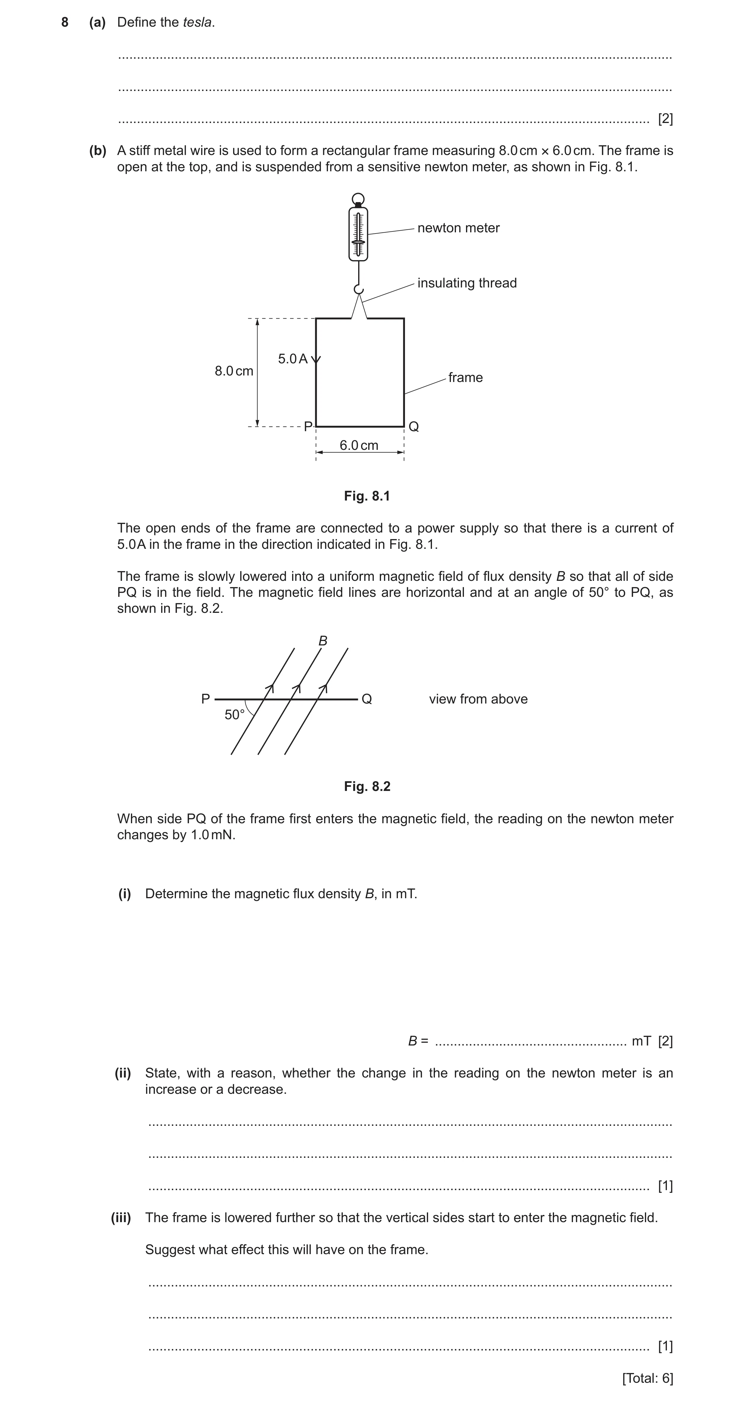
8 (a) Define the tesla. … … … [2] (b) A stiff metal wire is used to form a rectangular frame measuring 8.0 cm × 6.0 cm. The frame is open at the top, and is suspended from a sensitive newton meter, as shown in Fig. 8.1. newton meter insulating thread 5.0 A 8.0 cm frame P Q 6.0 cm Fig. 8.1 The open ends of the frame are connected to a power supply so that there is a current of 5.0 A in the frame in the direction indicated in Fig. 8.1. The frame is slowly lowered into a uniform magnetic field of flux density B so that all of side PQ is in the field. The magnetic field lines are horizontal and at an angle of 50° to PQ, as shown in Fig. 8.2. B P Q view from above 50° Fig. 8.2 When side PQ of the frame first enters the magnetic field, the reading on the newton meter changes by 1.0 mN. (i) Determine the magnetic flux density B, in mT. B = … mT [2] (ii) State, with a reason, whether the change in the reading on the newton meter is an increase or a decrease. … … … [1] (iii) The frame is lowered further so that the vertical sides start to enter the magnetic field. Suggest what effect this will have on the frame. … … … [1] [Total: 6]
6 marks
Mark scheme: 8(a) newton per ampere per metre M1 where current/wire is perpendicular to magnetic field A1 8(b)(i) F = BIL sinθ C1 B = 1.0 / (5.0 × 0.060 × sin 50°) = 4.4 mT A1 8(b)(ii) (from Fleming’s left-hand rule) force on wire is upwards, so reading decreases B1 8(b)(iii) frame will rotate (so that PQ becomes perpendicular to the field) B1
This question in 9702/43 Oct/Nov 2021
Q21 · A sphere of mass 1.6 × 10⁻¹⁰ kg has a charge of +0.27 nC 9702/41 May/June 2022
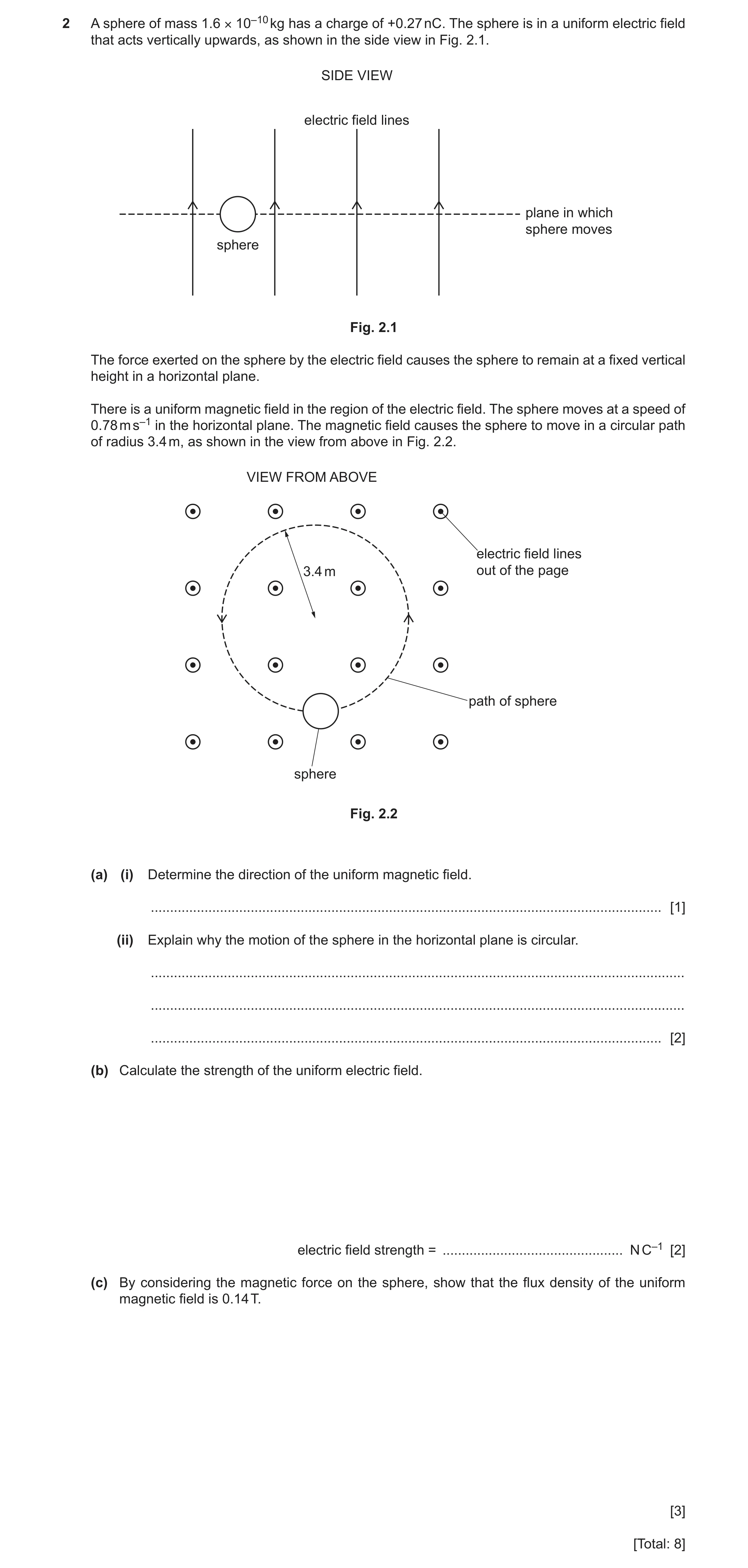
2 A sphere of mass 1.6 × 10⁻¹⁰ kg has a charge of +0.27 nC. The sphere is in a uniform electric field that acts vertically upwards, as shown in the side view in Fig. 2.1. SIDE VIEW electric field lines plane in which sphere moves sphere Fig. 2.1 The force exerted on the sphere by the electric field causes the sphere to remain at a fixed vertical height in a horizontal plane. There is a uniform magnetic field in the region of the electric field. The sphere moves at a speed of 0.78 m s–1 in the horizontal plane. The magnetic field causes the sphere to move in a circular path of radius 3.4 m, as shown in the view from above in Fig. 2.2. VIEW FROM ABOVE electric field lines 3.4 m out of the page path of sphere sphere Fig. 2.2 (a) (i) Determine the direction of the uniform magnetic field. … [1] (ii) Explain why the motion of the sphere in the horizontal plane is circular. … … … [2] (b) Calculate the strength of the uniform electric field. electric field strength = … N C–1 [2] (c) By considering the magnetic force on the sphere, show that the flux density of the uniform magnetic field is 0.14 T. [3] [Total: 8]
8 marks
Mark scheme: 2(a)(i) (vertically) downwards B1 2(a)(ii) magnetic force (on sphere) is perpendicular to its velocity B1 magnetic force perpendicular to velocity is the centripetal force or magnetic force perpendicular to velocity causes centripetal acceleration or acceleration perpendicular to velocity is centripetal (acceleration) or magnetic force does not change the speed of the sphere or magnetic force has constant magnitude B1 2(b) mg = Eq C1 E = (1.6 10–10 9.81) / (0.27 10–9) = 5.8 N C–1 A1 2(c) centripetal force = magnetic force or Bqv = mv2 / r B1 B = mv / qr C1 = (1.6 10–10 0.78) / (0.27 10–9 3.4) = 0.14 T A1
This question in 9702/41 May/June 2022
Q22 · A sphere of mass 1.6 × 10⁻¹⁰ kg has a charge of +0.27 nC 9702/43 May/June 2022
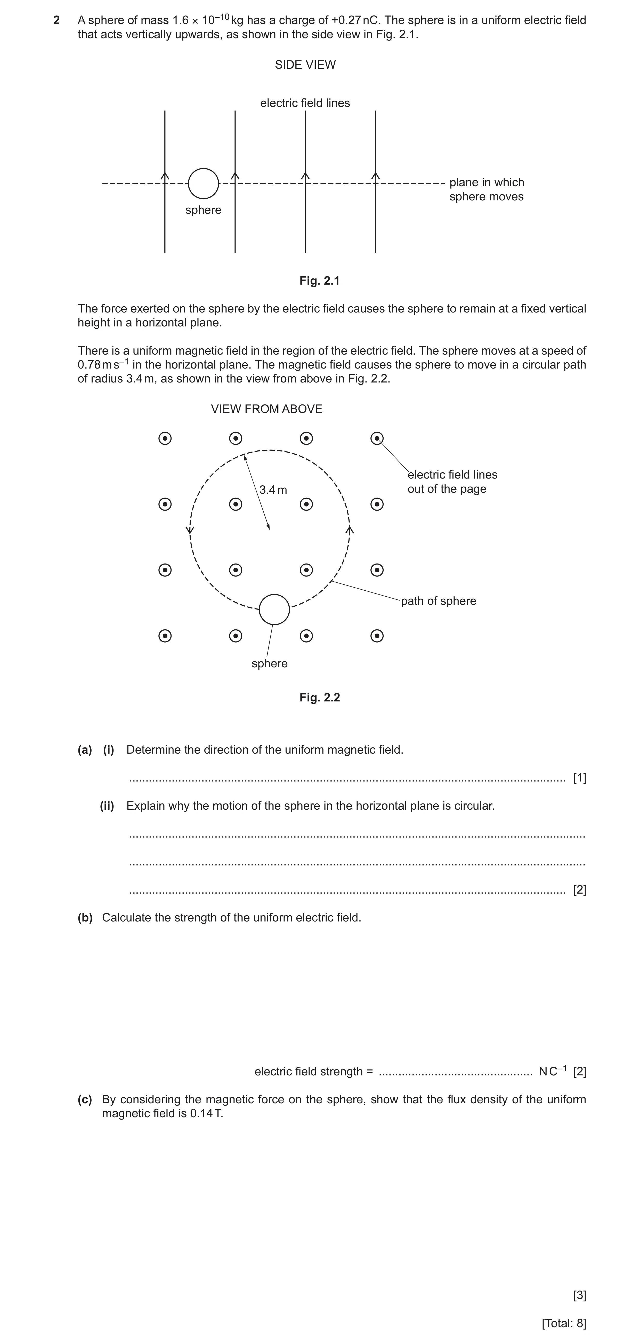
2 A sphere of mass 1.6 × 10⁻¹⁰ kg has a charge of +0.27 nC. The sphere is in a uniform electric field that acts vertically upwards, as shown in the side view in Fig. 2.1. SIDE VIEW electric field lines plane in which sphere moves sphere Fig. 2.1 The force exerted on the sphere by the electric field causes the sphere to remain at a fixed vertical height in a horizontal plane. There is a uniform magnetic field in the region of the electric field. The sphere moves at a speed of 0.78 m s–1 in the horizontal plane. The magnetic field causes the sphere to move in a circular path of radius 3.4 m, as shown in the view from above in Fig. 2.2. VIEW FROM ABOVE electric field lines 3.4 m out of the page path of sphere sphere Fig. 2.2 (a) (i) Determine the direction of the uniform magnetic field. … [1] (ii) Explain why the motion of the sphere in the horizontal plane is circular. … … … [2] (b) Calculate the strength of the uniform electric field. electric field strength = … N C–1 [2] (c) By considering the magnetic force on the sphere, show that the flux density of the uniform magnetic field is 0.14 T. [3] [Total: 8]
8 marks
Mark scheme: 2(a)(i) (vertically) downwards B1 2(a)(ii) magnetic force (on sphere) is perpendicular to its velocity B1 magnetic force perpendicular to velocity is the centripetal force or magnetic force perpendicular to velocity causes centripetal acceleration or acceleration perpendicular to velocity is centripetal (acceleration) or magnetic force does not change the speed of the sphere or magnetic force has constant magnitude B1 2(b) mg = Eq C1 E = (1.6 10–10 9.81) / (0.27 10–9) = 5.8 N C–1 A1 2(c) centripetal force = magnetic force or Bqv = mv2 / r B1 B = mv / qr C1 = (1.6 10–10 0.78) / (0.27 10–9 3.4) = 0.14 T A1
This question in 9702/43 May/June 2022
Q23 · Define magnetic flux density 9702/42 Oct/Nov 2022
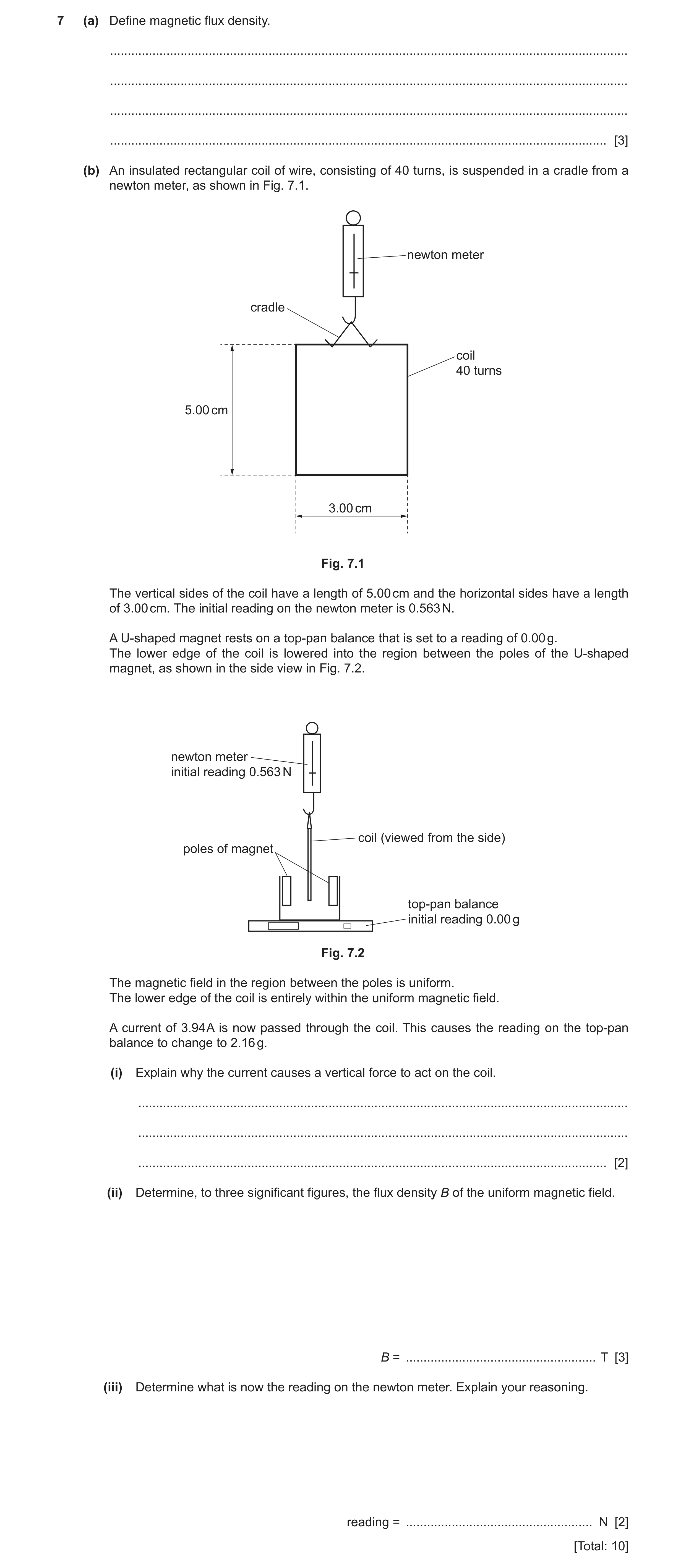
7 (a) Define magnetic flux density. … … … … [3] (b) An insulated rectangular coil of wire, consisting of 40 turns, is suspended in a cradle from a newton meter, as shown in Fig. 7.1. newton meter cradle coil 40 turns 5.00 cm 3.00 cm Fig. 7.1 The vertical sides of the coil have a length of 5.00 cm and the horizontal sides have a length of 3.00 cm. The initial reading on the newton meter is 0.563 N. A U-shaped magnet rests on a top-pan balance that is set to a reading of 0.00 g. The lower edge of the coil is lowered into the region between the poles of the U-shaped magnet, as shown in the side view in Fig. 7.2. newton meter initial reading 0.563 N coil (viewed from the side) poles of magnet top-pan balance initial reading 0.00 g Fig. 7.2 The magnetic field in the region between the poles is uniform. The lower edge of the coil is entirely within the uniform magnetic field. A current of 3.94 A is now passed through the coil. This causes the reading on the top-pan balance to change to 2.16 g. (i) Explain why the current causes a vertical force to act on the coil. … … … [2] (ii) Determine, to three significant figures, the flux density B of the uniform magnetic field. B = … T [3] (iii) Determine what is now the reading on the newton meter. Explain your reasoning. reading = … N [2] [Total: 10]
10 marks
Mark scheme: 7(a) force per unit current M1 force per unit length M1 current / wire is perpendicular to (magnetic) field (lines) A1 7(b)(i) current (in coil) is perpendicular to magnetic field (so force on wire) B1 force (on wire) is perpendicular to current and field (so is vertical) B1 or current and field are both horizontal (so force is vertical) 7(b)(ii) NBIL = mg C1 B = (2.16 10–3 9.81) / (40 3.94 0.0300) C1 = 4.48 10–3 T A1 7(b)(iii) (magnetic) forces (on balance and newton meter) are (equal and) opposite B1 reading = 0.563 – (2.16 10–3 9.81) A1 = 0.542 N
This question in 9702/42 Oct/Nov 2022
Q24 · A Hall probe is placed in a magnetic field 9702/42 Feb/March 2023
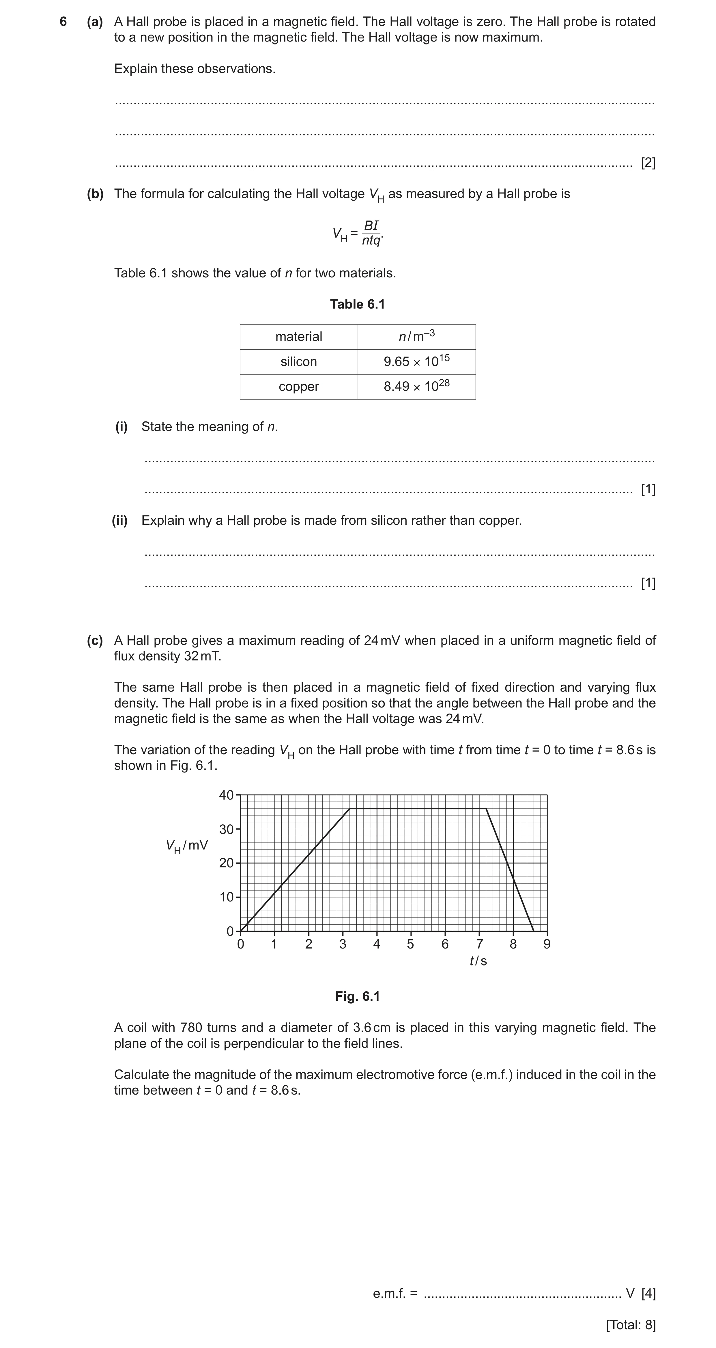
6 (a) A Hall probe is placed in a magnetic field. The Hall voltage is zero. The Hall probe is rotated to a new position in the magnetic field. The Hall voltage is now maximum. Explain these observations. … … … [2] (b) The formula for calculating the Hall voltage VH as measured by a Hall probe is BI VH = ntq. Table 6.1 shows the value of n for two materials. Table 6.1 material n / m–3 silicon 9.65 × 10¹⁵ copper 8.49 × 1028 (i) State the meaning of n. … … [1] (ii) Explain why a Hall probe is made from silicon rather than copper. … … [1] (c) A Hall probe gives a maximum reading of 24 mV when placed in a uniform magnetic field of flux density 32 mT. The same Hall probe is then placed in a magnetic field of fixed direction and varying flux density. The Hall probe is in a fixed position so that the angle between the Hall probe and the magnetic field is the same as when the Hall voltage was 24 mV. The variation of the reading VH on the Hall probe with time t from time t = 0 to time t = 8.6 s is shown in Fig. 6.1. 40 30 VH / mV 20 10 0 0 1 2 3 4 5 6 7 8 9 t / s Fig. 6.1 A coil with 780 turns and a diameter of 3.6 cm is placed in this varying magnetic field. The plane of the coil is perpendicular to the field lines. Calculate the magnitude of the maximum electromotive force (e.m.f.) induced in the coil in the time between t = 0 and t = 8.6 s. e.m.f. = … V [4] [Total: 8]
8 marks
Mark scheme: 6(a) it is zero when (plane of) probe is parallel to the (magnetic) field (lines) B1 it is maximum when (plane of) probe is perpendicular to (magnetic) field (lines) B1 6(b)(i) number density of charge carriers B1 6(b)(ii) smaller value of n so greater Hall voltage / VH B1 6(c) (36 mV corresponds to) 48 mT C1 use of 1.4 s or (8.6 – 7.2) s C1 E = BAN / t C1 48 10 −3 0.018 2 780 A1 = 1.4 = 0.027 V
This question in 9702/42 Feb/March 2023
Q25 · State what is meant by a magnetic field 9702/41 May/June 2023
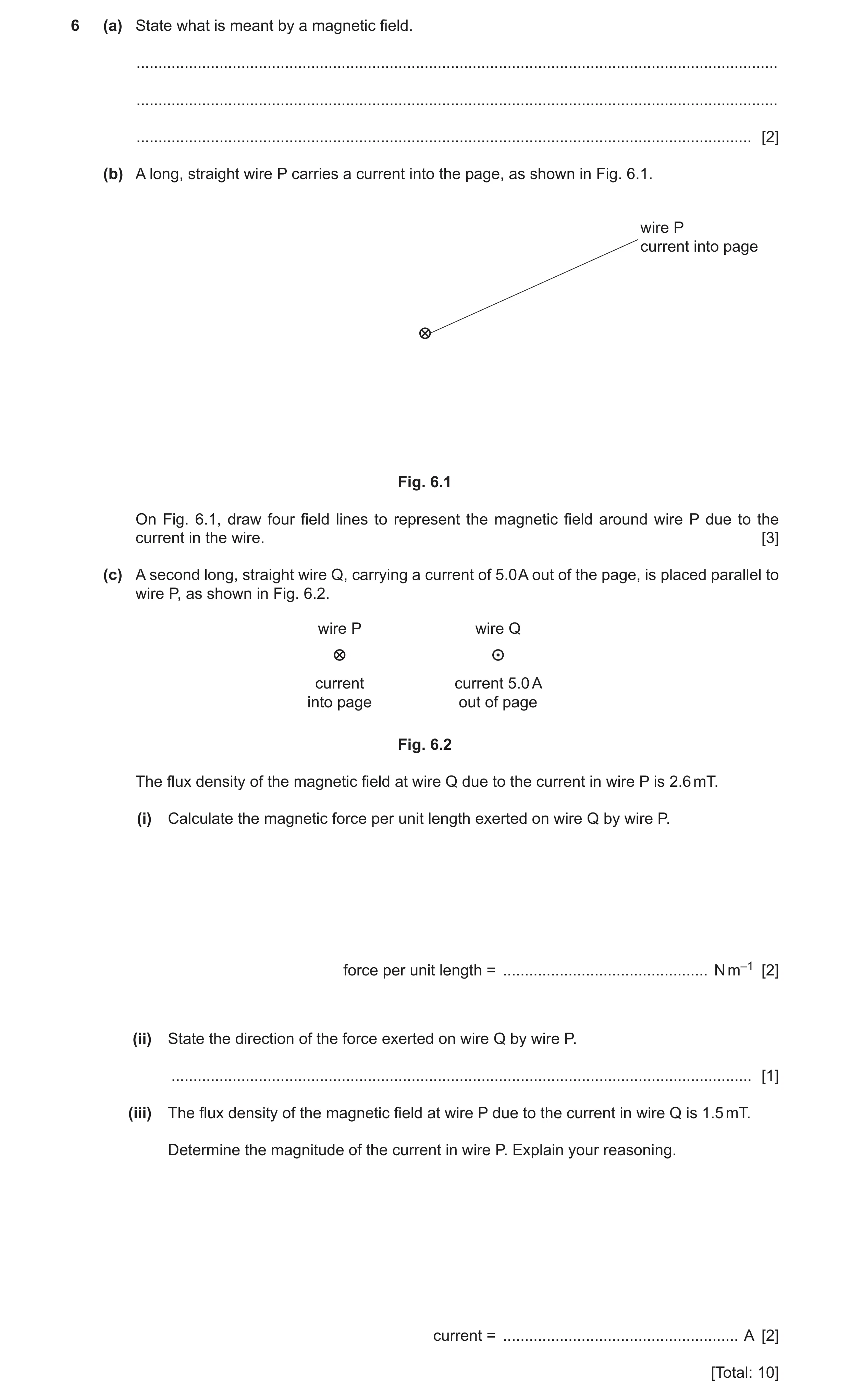
6 (a) State what is meant by a magnetic field. … … … [2] (b) A long, straight wire P carries a current into the page, as shown in Fig. 6.1. wire P current into page Fig. 6.1 On Fig. 6.1, draw four field lines to represent the magnetic field around wire P due to the current in the wire. [3] (c) A second long, straight wire Q, carrying a current of 5.0 A out of the page, is placed parallel to wire P, as shown in Fig. 6.2. wire P wire Q current current 5.0 A into page out of page Fig. 6.2 The flux density of the magnetic field at wire Q due to the current in wire P is 2.6 mT. (i) Calculate the magnetic force per unit length exerted on wire Q by wire P. force per unit length = … N m–1 [2] (ii) State the direction of the force exerted on wire Q by wire P. … [1] (iii) The flux density of the magnetic field at wire P due to the current in wire Q is 1.5 mT. Determine the magnitude of the current in wire P. Explain your reasoning. current = … A [2] [Total: 10]
10 marks
Mark scheme: 6(a) a region where a force acts on M1 a current-carrying conductor or a moving charge or a magnetic material / magnetic pole A1 6(b) concentric circles around the wire B1 spacing between circles increases with distance from wire B1 arrows showing direction of field is clockwise B1 6(c)(i) F = BIL C1 force per unit length = BI = 2.6 10–3 5.0 = 0.013 N m–1 A1 6(c)(ii) to the right B1 6(c)(iii) force (per unit length) has the same magnitude due to Newton’s 3rd law B1 0.013 = 1.5 10–3 I current = 8.7 A A1
This question in 9702/41 May/June 2023
Q26 · State what is meant by a magnetic field 9702/43 May/June 2023
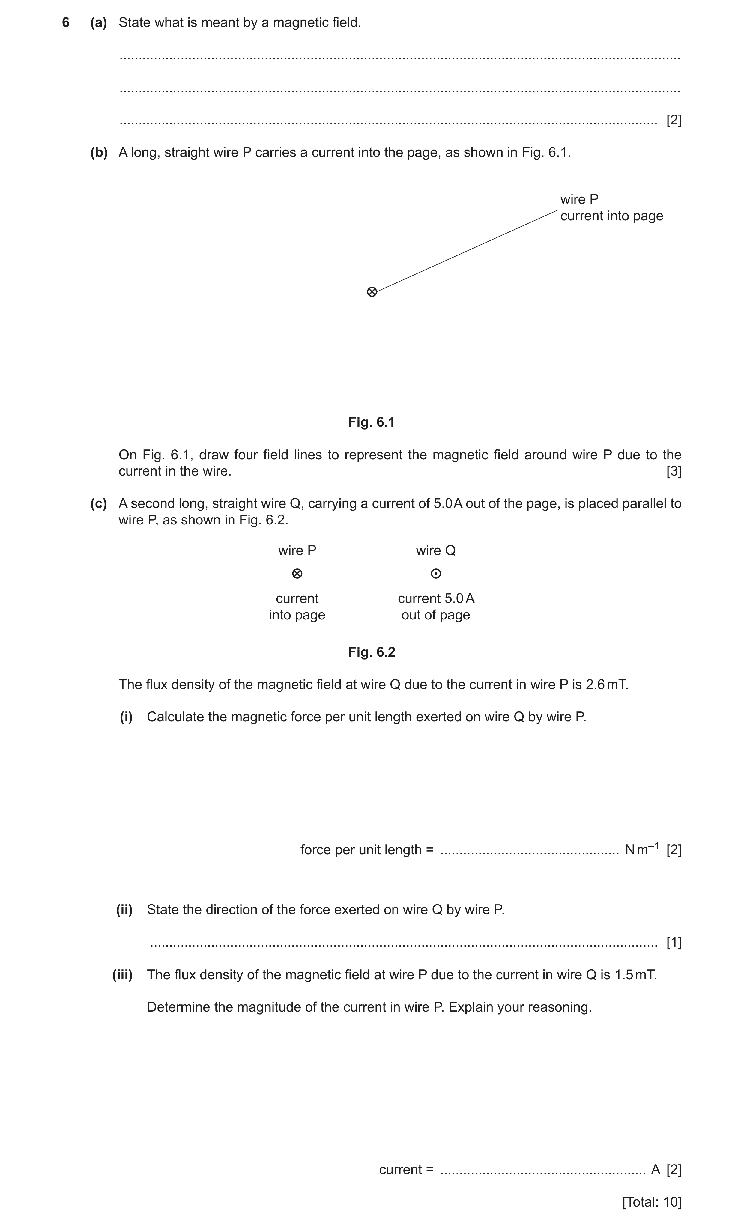
6 (a) State what is meant by a magnetic field. … … … [2] (b) A long, straight wire P carries a current into the page, as shown in Fig. 6.1. wire P current into page Fig. 6.1 On Fig. 6.1, draw four field lines to represent the magnetic field around wire P due to the current in the wire. [3] (c) A second long, straight wire Q, carrying a current of 5.0 A out of the page, is placed parallel to wire P, as shown in Fig. 6.2. wire P wire Q current current 5.0 A into page out of page Fig. 6.2 The flux density of the magnetic field at wire Q due to the current in wire P is 2.6 mT. (i) Calculate the magnetic force per unit length exerted on wire Q by wire P. force per unit length = … N m–1 [2] (ii) State the direction of the force exerted on wire Q by wire P. … [1] (iii) The flux density of the magnetic field at wire P due to the current in wire Q is 1.5 mT. Determine the magnitude of the current in wire P. Explain your reasoning. current = … A [2] [Total: 10]
10 marks
Mark scheme: 6(a) a region where a force acts on M1 a current-carrying conductor or a moving charge or a magnetic material / magnetic pole A1 6(b) concentric circles around the wire B1 spacing between circles increases with distance from wire B1 arrows showing direction of field is clockwise B1 6(c)(i) F = BIL C1 force per unit length = BI = 2.6 10–3 5.0 = 0.013 N m–1 A1 6(c)(ii) to the right B1 6(c)(iii) force (per unit length) has the same magnitude due to Newton’s 3rd law B1 0.013 = 1.5 10–3 I current = 8.7 A A1
This question in 9702/43 May/June 2023
Q27 · Define magnetic flux density 9702/41 Oct/Nov 2023
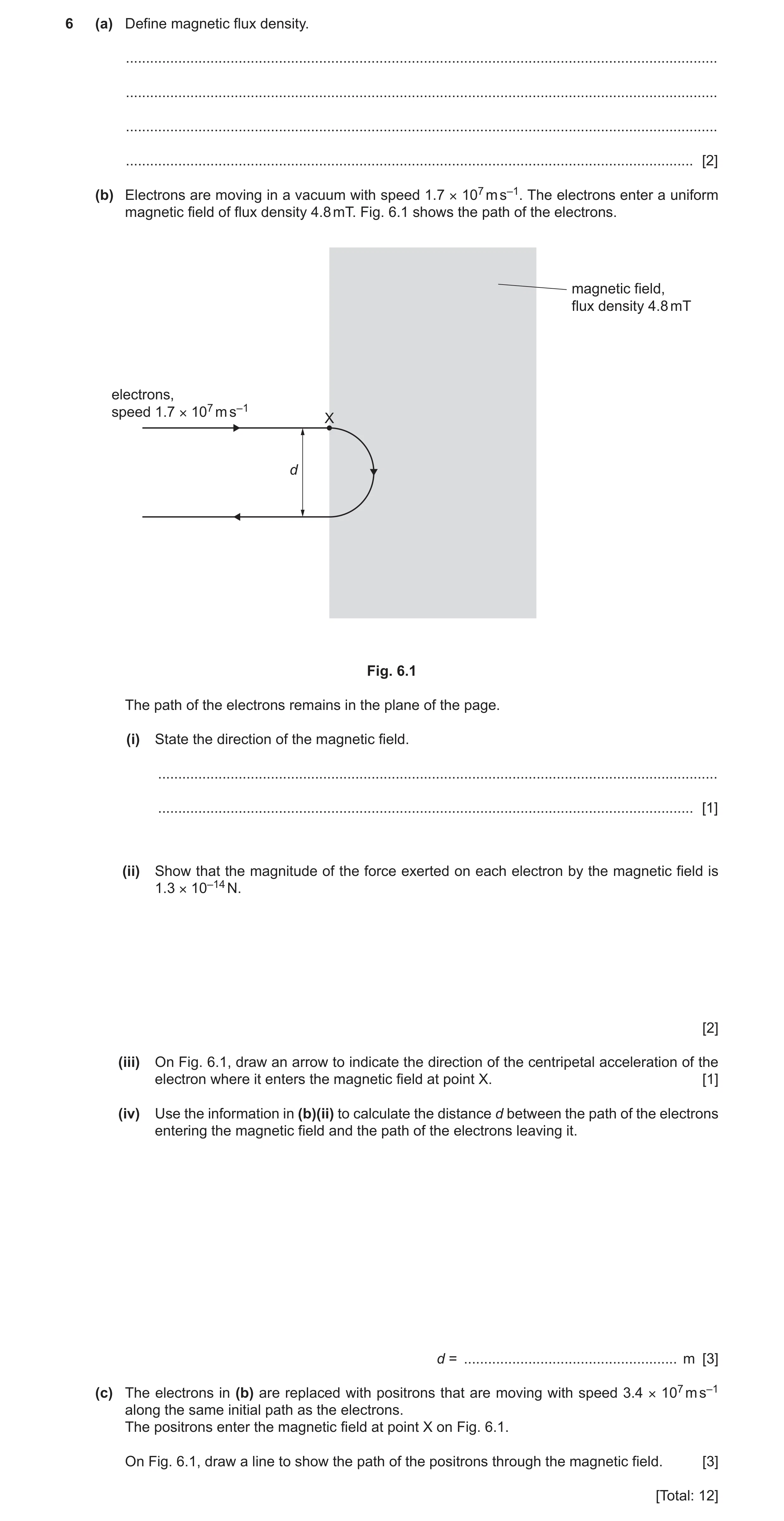
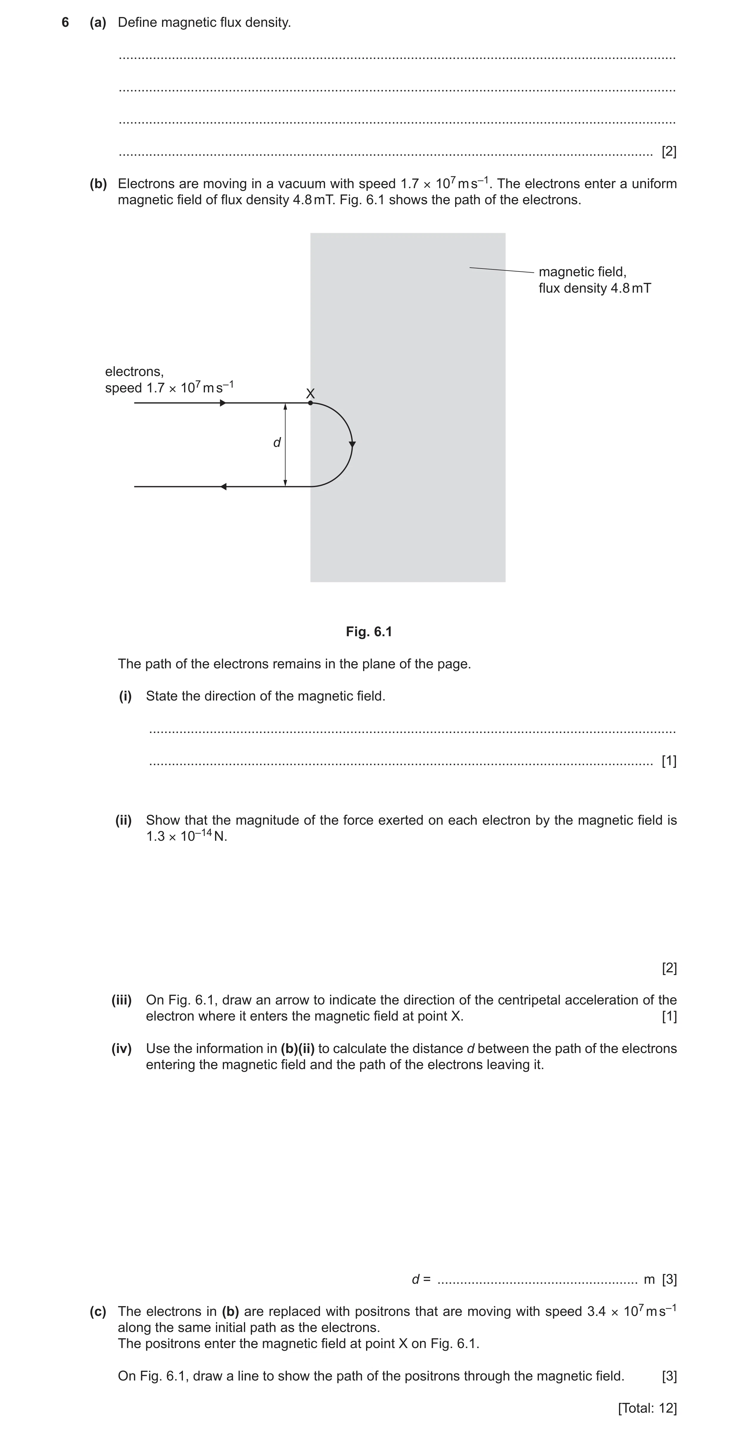
6 (a) Define magnetic flux density. … … … … [2] (b) Electrons are moving in a vacuum with speed 1.7 × 10⁷ m s–1. The electrons enter a uniform magnetic field of flux density 4.8 mT. Fig. 6.1 shows the path of the electrons. magnetic field, flux density 4.8 mT electrons, speed 1.7 × 10⁷ m s–1 X d Fig. 6.1 The path of the electrons remains in the plane of the page. (i) State the direction of the magnetic field. … … [1] (ii) Show that the magnitude of the force exerted on each electron by the magnetic field is 1.3 × 10⁻¹⁴ N. [2] (iii) On Fig. 6.1, draw an arrow to indicate the direction of the centripetal acceleration of the electron where it enters the magnetic field at point X. [1] (iv) Use the information in (b)(ii) to calculate the distance d between the path of the electrons entering the magnetic field and the path of the electrons leaving it. d = … m [3] (c) The electrons in (b) are replaced with positrons that are moving with speed 3.4 × 10⁷ m s–1 along the same initial path as the electrons. The positrons enter the magnetic field at point X on Fig. 6.1. On Fig. 6.1, draw a line to show the path of the positrons through the magnetic field. [3] [Total: 12]
12 marks
Mark scheme: 6(a) • force per unit length B2 • force per unit current • length / current perpendicular to field 1 mark for any two points, 2 marks for all three points 6(b)(i) into the page B1 6(b)(ii) F = Bqv C1 = 4.8 10–3 1.6 10–19 1.7 107 = 1.3 10–14 N A1 6(b)(iii) arrow at point X pointing down the page B1 6(b)(iv) F = mv2 / r C1 1.3 10–14 = (9.11 10–31) (1.7 107)2 / r C1 (r = 0.020 m) A1 d = 2r d = 0.040 m 6(c) path shows upwards deflection such that the curvature is always anticlockwise within the field B1 circular path with larger radius B1 line enters field at X and leaves field at distance 2d vertically from X B1
This question in 9702/41 Oct/Nov 2023
Q28 · A Hall probe containing a thin slice of semiconducting material is placed in a uniform… 9702/42 Oct/Nov 2023
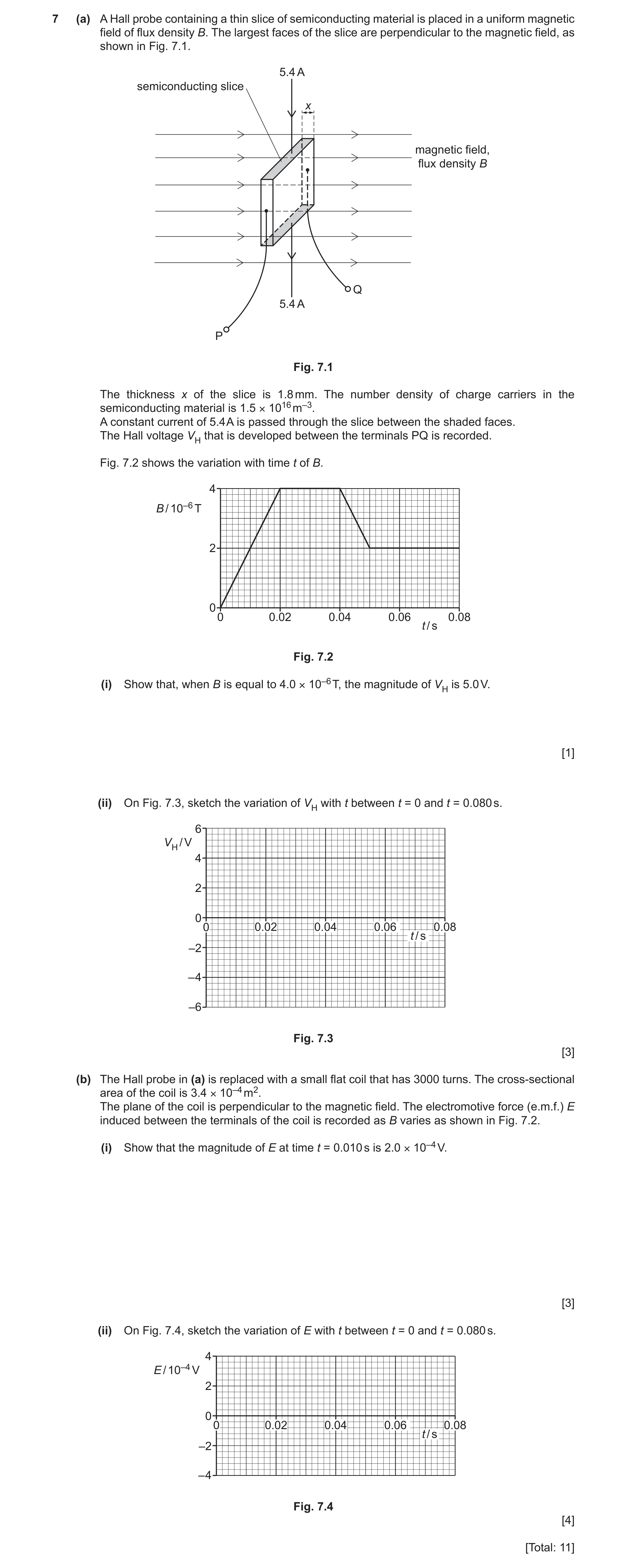
7 (a) A Hall probe containing a thin slice of semiconducting material is placed in a uniform magnetic field of flux density B. The largest faces of the slice are perpendicular to the magnetic field, as shown in Fig. 7.1. 5.4 A semiconducting slice x magnetic field, flux density B Q 5.4 A P Fig. 7.1 The thickness x of the slice is 1.8 mm. The number density of charge carriers in the semiconducting material is 1.5 × 10¹⁶ m–3. A constant current of 5.4 A is passed through the slice between the shaded faces. The Hall voltage VH that is developed between the terminals PQ is recorded. Fig. 7.2 shows the variation with time t of B. 4 B / 10–6 T 2 0 0 0.02 0.04 0.06 0.08 t / s Fig. 7.2 (i) Show that, when B is equal to 4.0 × 10⁻⁶ T, the magnitude of VH is 5.0 V. [1] (ii) On Fig. 7.3, sketch the variation of VH with t between t = 0 and t = 0.080 s. 6 VH / V 4 2 0 0 0.02 0.04 0.06 0.08 t / s –2 – 4 –6 Fig. 7.3 [3] (b) The Hall probe in (a) is replaced with a small flat coil that has 3000 turns. The cross-sectional area of the coil is 3.4 × 10⁻⁴ m2. The plane of the coil is perpendicular to the magnetic field. The electromotive force (e.m.f.) E induced between the terminals of the coil is recorded as B varies as shown in Fig. 7.2. (i) Show that the magnitude of E at time t = 0.010 s is 2.0 × 10⁻⁴ V. [3] (ii) On Fig. 7.4, sketch the variation of E with t between t = 0 and t = 0.080 s. 4 E / 10–4 V 2 0 0 0.02 0.04 0.06 0.08 t / s –2 – 4 Fig. 7.4 [4] [Total: 11]
11 marks
Mark scheme: 7(a)(i) VH = BI / ntq A1 = (4.0 10–6 5.4) / (1.5 1016 1.8 10–3 1.60 10–19) = 5.0 V 7(a)(ii) sketch: straight diagonal line from (0, 0) to t = 0.020 s B1 and straight diagonal line between two non-zero VH values of same sign from t = 0.040 to 0.050 s horizontal straight line at VH = 5.0 V from t = 0.020 to 0.040 s B1 horizontal straight line at VH = 2.5 V from t = 0.050 to 0.080 s B1 7(b)(i) e.m.f. = rate of change of (magnetic) flux (linkage) C1 E = NA ΔB / Δt or E = NA gradient (at t = 0.010 s) C1 E = 3000 3.4 10–4 (4.0 10–6) / (0.020) = 2.0 10–4 V A1 7(b)(ii) sketch: line showing non-zero E from t = 0 to t = 0.020 s and from t = 0.040 s to t = 0.050 s, and E = 0 at all other times B1 ‘top hats’ showing constant non-zero E from t = 0 to t = 0.020 s and from t = 0.040 s to t = 0.050 s B1 magnitude of E shown as 2.0 10–4 V in both non-zero sections B1 sign of E in the t = 0 to t = 0.020 s region opposite to the sign of E in the t = 0.040 s to t = 0.050 s region B1
This question in 9702/42 Oct/Nov 2023
Q29 · Define magnetic flux density 9702/43 Oct/Nov 2023
6 (a) Define magnetic flux density. … … … … [2] (b) Electrons are moving in a vacuum with speed 1.7 × 10⁷ m s–1. The electrons enter a uniform magnetic field of flux density 4.8 mT. Fig. 6.1 shows the path of the electrons. magnetic field, flux density 4.8 mT electrons, speed 1.7 × 10⁷ m s–1 X d Fig. 6.1 The path of the electrons remains in the plane of the page. (i) State the direction of the magnetic field. … … [1] (ii) Show that the magnitude of the force exerted on each electron by the magnetic field is 1.3 × 10⁻¹⁴ N. [2] (iii) On Fig. 6.1, draw an arrow to indicate the direction of the centripetal acceleration of the electron where it enters the magnetic field at point X. [1] (iv) Use the information in (b)(ii) to calculate the distance d between the path of the electrons entering the magnetic field and the path of the electrons leaving it. d = … m [3] (c) The electrons in (b) are replaced with positrons that are moving with speed 3.4 × 10⁷ m s–1 along the same initial path as the electrons. The positrons enter the magnetic field at point X on Fig. 6.1. On Fig. 6.1, draw a line to show the path of the positrons through the magnetic field. [3] [Total: 12]
12 marks
Mark scheme: 6(a) • force per unit length B2 • force per unit current • length / current perpendicular to field 1 mark for any two points, 2 marks for all three points 6(b)(i) into the page B1 6(b)(ii) F = Bqv C1 = 4.8 10–3 1.6 10–19 1.7 107 = 1.3 10–14 N A1 6(b)(iii) arrow at point X pointing down the page B1 6(b)(iv) F = mv2 / r C1 1.3 10–14 = (9.11 10–31) (1.7 107)2 / r C1 (r = 0.020 m) A1 d = 2r d = 0.040 m 6(c) path shows upwards deflection such that the curvature is always anticlockwise within the field B1 circular path with larger radius B1 line enters field at X and leaves field at distance 2d vertically from X B1
This question in 9702/43 Oct/Nov 2023
Q30 · Define magnetic flux density 9702/41 Oct/Nov 2024
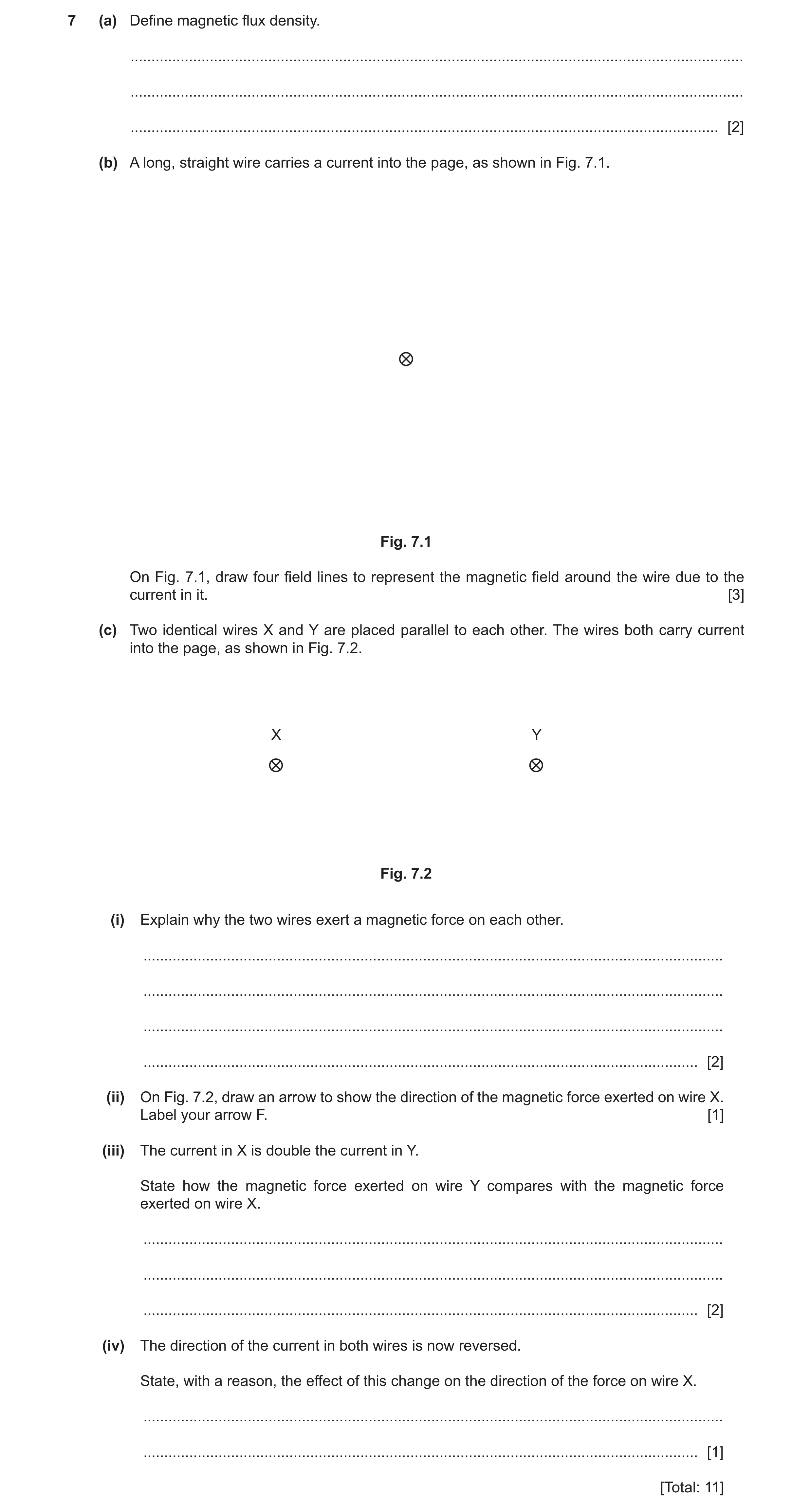
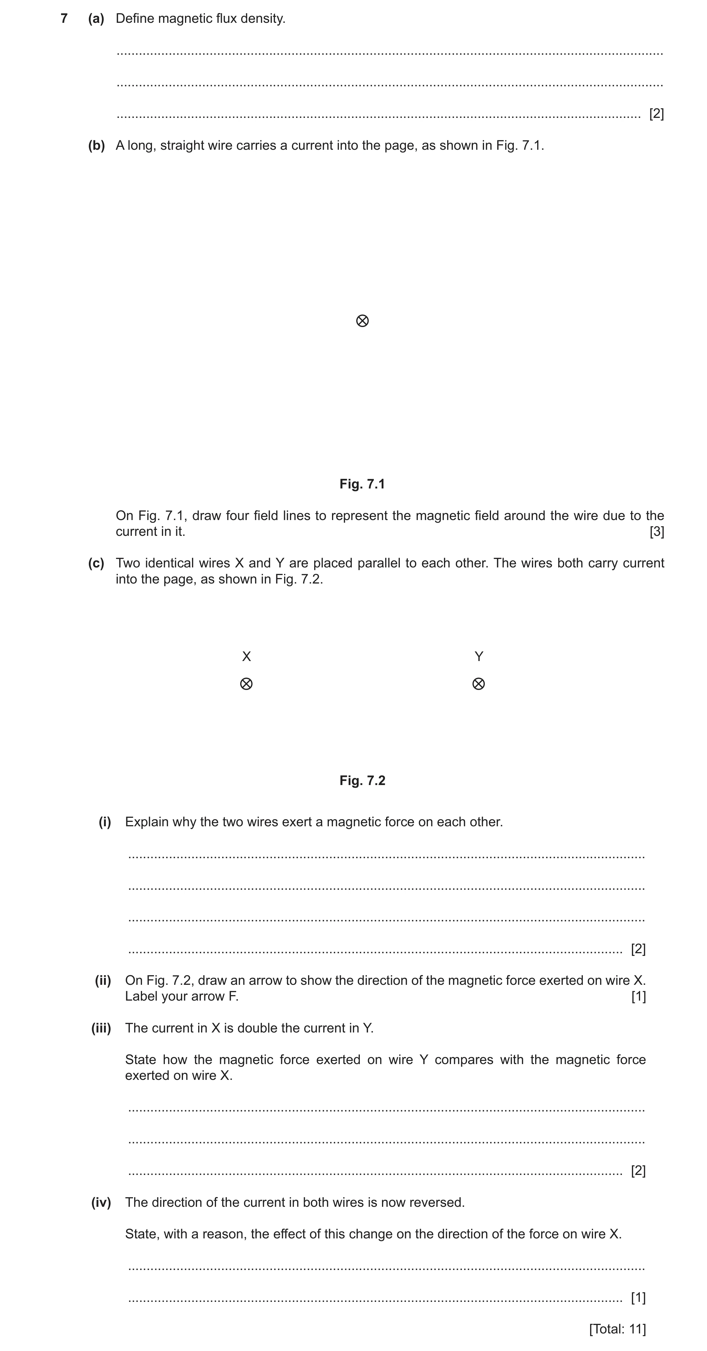
7 (a) Define magnetic flux density. … … … [2] (b) A long, straight wire carries a current into the page, as shown in Fig. 7.1. Fig. 7.1 On Fig. 7.1, draw four field lines to represent the magnetic field around the wire due to the current in it. [3] (c) Two identical wires X and Y are placed parallel to each other. The wires both carry current into the page, as shown in Fig. 7.2. X Y Fig. 7.2 (i) Explain why the two wires exert a magnetic force on each other. … … … … [2] (ii) On Fig. 7.2, draw an arrow to show the direction of the magnetic force exerted on wire X. Label your arrow F. [1] (iii) The current in X is double the current in Y. State how the magnetic force exerted on wire Y compares with the magnetic force exerted on wire X. … … … [2] (iv) The direction of the current in both wires is now reversed. State, with a reason, the effect of this change on the direction of the force on wire X. … … [1] [Total: 11]
11 marks
Mark scheme: 7(a) • force per unit length B2 • force per unit current • length / current perpendicular to field 1 mark for any two points, 2 marks for all three points 7(b) concentric circles around the wire (at least two circles needed) B1 spacing between circles increases with distance from wire (at least four circles needed) B1 arrows showing direction of field is clockwise B1 7(c)(i) (each) wire sits in the (magnetic) field created by the other B1 current (in one wire) is perpendicular to (magnetic) field (due to other wire) so (magnetic) force acts (on wire) B1 7(c)(ii) arrow drawn, starting from X and pointing towards Y, labelled F B1 7(c)(iii) (forces have) equal magnitudes B1 (forces are in) opposite directions B1 7(c)(iv) no change (in the direction of the force) since both the current in X and the field due to Y have reversed B1
This question in 9702/41 Oct/Nov 2024
Q31 · Define magnetic flux density 9702/43 Oct/Nov 2024
7 (a) Define magnetic flux density. … … … [2] (b) A long, straight wire carries a current into the page, as shown in Fig. 7.1. Fig. 7.1 On Fig. 7.1, draw four field lines to represent the magnetic field around the wire due to the current in it. [3] (c) Two identical wires X and Y are placed parallel to each other. The wires both carry current into the page, as shown in Fig. 7.2. X Y Fig. 7.2 (i) Explain why the two wires exert a magnetic force on each other. … … … … [2] (ii) On Fig. 7.2, draw an arrow to show the direction of the magnetic force exerted on wire X. Label your arrow F. [1] (iii) The current in X is double the current in Y. State how the magnetic force exerted on wire Y compares with the magnetic force exerted on wire X. … … … [2] (iv) The direction of the current in both wires is now reversed. State, with a reason, the effect of this change on the direction of the force on wire X. … … [1] [Total: 11]
11 marks
Mark scheme: 7(a) • force per unit length B2 • force per unit current • length / current perpendicular to field 1 mark for any two points, 2 marks for all three points 7(b) concentric circles around the wire (at least two circles needed) B1 spacing between circles increases with distance from wire (at least four circles needed) B1 arrows showing direction of field is clockwise B1 7(c)(i) (each) wire sits in the (magnetic) field created by the other B1 current (in one wire) is perpendicular to (magnetic) field (due to other wire) so (magnetic) force acts (on wire) B1 7(c)(ii) arrow drawn, starting from X and pointing towards Y, labelled F B1 7(c)(iii) (forces have) equal magnitudes B1 (forces are in) opposite directions B1 7(c)(iv) no change (in the direction of the force) since both the current in X and the field due to Y have reversed B1
This question in 9702/43 Oct/Nov 2024
Q32 · Define magnetic flux density 9702/41 May/June 2025
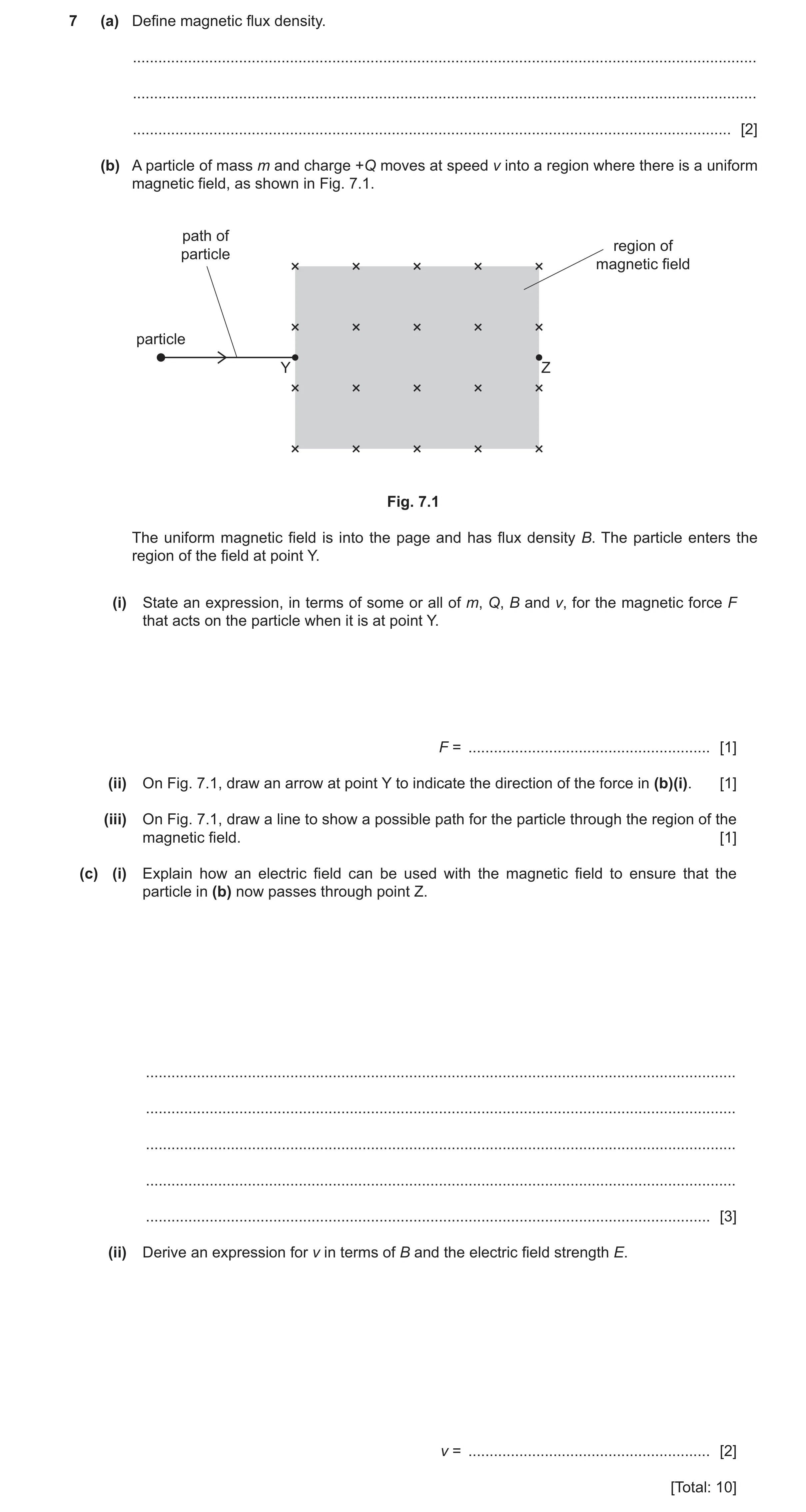
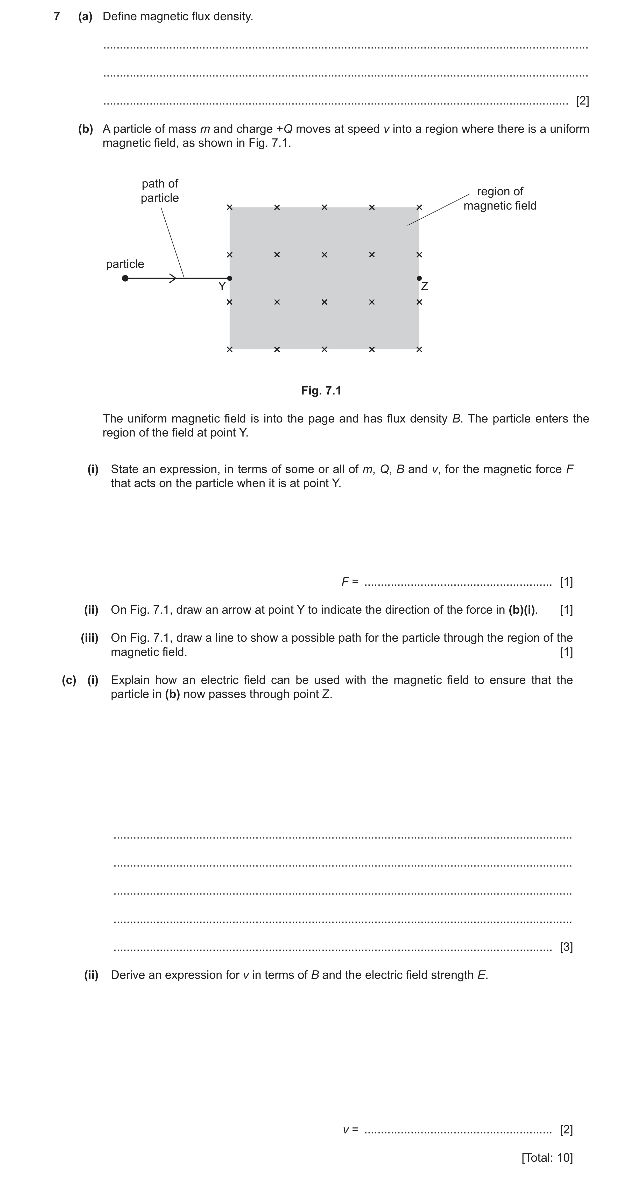
7 (a) Define magnetic flux density. … … … [2] (b) A particle of mass m and charge +Q moves at speed v into a region where there is a uniform magnetic field, as shown in Fig. 7.1. path of region of particle magnetic field particle Y Z Fig. 7.1 The uniform magnetic field is into the page and has flux density B. The particle enters the region of the field at point Y. (i) State an expression, in terms of some or all of m, Q, B and v, for the magnetic force F that acts on the particle when it is at point Y. F = … [1] (ii) On Fig. 7.1, draw an arrow at point Y to indicate the direction of the force in (b)(i). [1] (iii) On Fig. 7.1, draw a line to show a possible path for the particle through the region of the magnetic field. [1] (c) (i) Explain how an electric field can be used with the magnetic field to ensure that the particle in (b) now passes through point Z. … … … … … [3] (ii) Derive an expression for v in terms of B and the electric field strength E. v = … [2] [Total: 10]
10 marks
Mark scheme: 7(a) • force per unit length B2 • force per unit current • length / current perpendicular to field 1 mark for any two points, 2 marks for all three points. 7(b)(i) F = BQv B1 7(b)(ii) arrow at Y pointing vertically upwards B1 7(b)(iii) upwards deflection showing circular path B1 7(c)(i) electric field applied vertically downwards (may be shown on a labelled diagram) B1 electric force on particle in opposite direction to magnetic force (may be shown on a labelled diagram) B1 particle undeflected when magnitudes of electric and magnetic forces are equal B1 7(c)(ii) EQ = BQv B1 v = E / B A1
This question in 9702/41 May/June 2025
Q33 · State what is represented by a gravitational field line 9702/42 May/June 2025
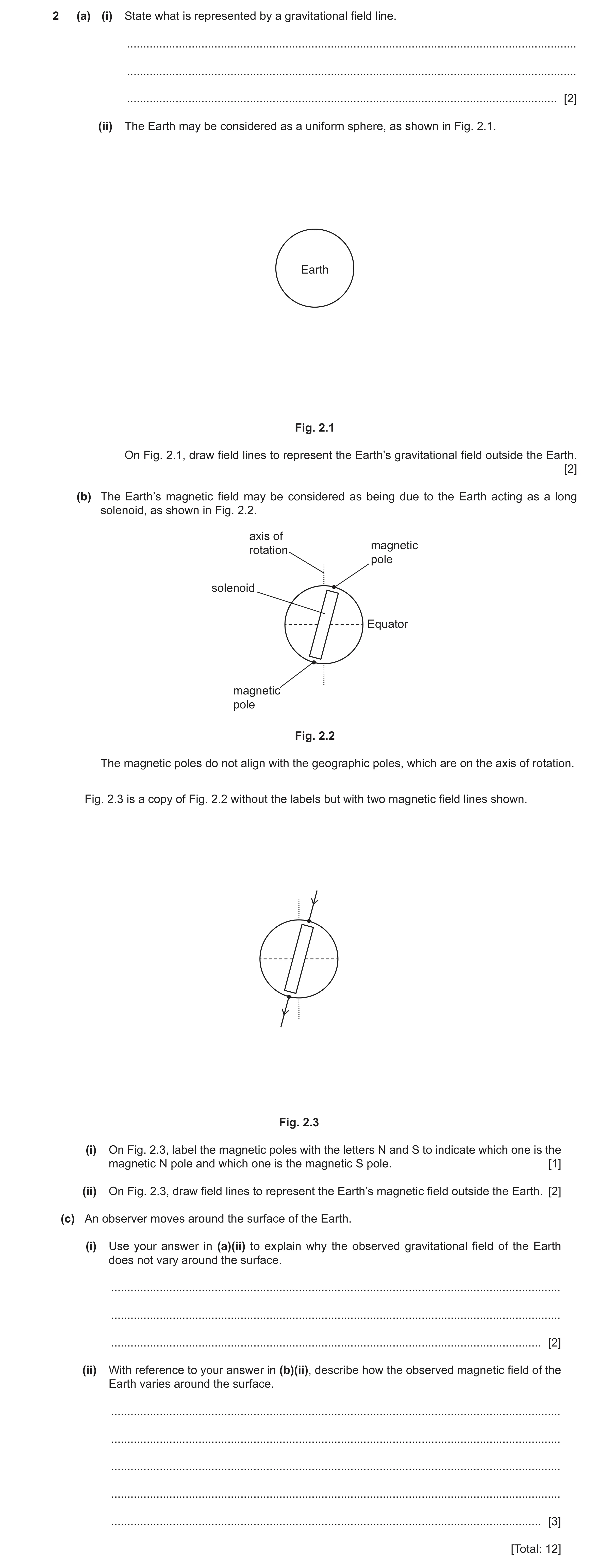
2 (a) (i) State what is represented by a gravitational field line. … … … [2] (ii) The Earth may be considered as a uniform sphere, as shown in Fig. 2.1. Earth Fig. 2.1 On Fig. 2.1, draw field lines to represent the Earth’s gravitational field outside the Earth. [2] (b) The Earth’s magnetic field may be considered as being due to the Earth acting as a long solenoid, as shown in Fig. 2.2. axis of magnetic rotation pole solenoid Equator magnetic pole Fig. 2.2 The magnetic poles do not align with the geographic poles, which are on the axis of rotation. Fig. 2.3 is a copy of Fig. 2.2 without the labels but with two magnetic field lines shown. Fig. 2.3 (i) On Fig. 2.3, label the magnetic poles with the letters N and S to indicate which one is the magnetic N pole and which one is the magnetic S pole. [1] (ii) On Fig. 2.3, draw field lines to represent the Earth’s magnetic field outside the Earth. [2] (c) An observer moves around the surface of the Earth. (i) Use your answer in (a)(ii) to explain why the observed gravitational field of the Earth does not vary around the surface. … … … [2] (ii) With reference to your answer in (b)(ii), describe how the observed magnetic field of the Earth varies around the surface. … … … … … [3] [Total: 12]
12 marks
Mark scheme: 2(a)(i) direction of force B1 force acting on a (test) mass B1 2(a)(ii) at least four radial lines from the Earth’s surface, equally spaced around the surface B1 arrows indicating direction towards Earth B1 2(b)(i) top pole labelled S and bottom pole labelled N B1 2(b)(ii) solenoid field pattern at the poles: B1 at least two field lines either side of both poles, close to the poles, clustered closely together, leaving the surface approximately perpendicularly to the surface and curving away from the axis of the poles as their distance from the surface increases solenoid field pattern above the equator: B1 at least one field line either side of the Earth connecting two points on the surface that are on the same side of the poles, one north of the equator and one south of it, passing above the surface near the magnetic equator approximately parallel to the surface 2(c)(i) (around the surface) lines are evenly spaced B1 all lines perpendicular to surface B1 or pointing down towards surface (at all points around the surface) 2(c)(ii) Any three bulleted points from: B3 • strongest at the poles • weakest near the Equator Up to two points from: • perpendicular to surface at the poles • parallel to the surface near the Equator • angle to surface increases from Equator to poles
This question in 9702/42 May/June 2025
Q34 · Define magnetic flux density 9702/43 May/June 2025
7 (a) Define magnetic flux density. … … … [2] (b) A particle of mass m and charge +Q moves at speed v into a region where there is a uniform magnetic field, as shown in Fig. 7.1. path of region of particle magnetic field particle Y Z Fig. 7.1 The uniform magnetic field is into the page and has flux density B. The particle enters the region of the field at point Y. (i) State an expression, in terms of some or all of m, Q, B and v, for the magnetic force F that acts on the particle when it is at point Y. F = … [1] (ii) On Fig. 7.1, draw an arrow at point Y to indicate the direction of the force in (b)(i). [1] (iii) On Fig. 7.1, draw a line to show a possible path for the particle through the region of the magnetic field. [1] (c) (i) Explain how an electric field can be used with the magnetic field to ensure that the particle in (b) now passes through point Z. … … … … … [3] (ii) Derive an expression for v in terms of B and the electric field strength E. v = … [2] [Total: 10]
10 marks
Mark scheme: 7(a) • force per unit length B2 • force per unit current • length / current perpendicular to field 1 mark for any two points, 2 marks for all three points. 7(b)(i) F = BQv B1 7(b)(ii) arrow at Y pointing vertically upwards B1 7(b)(iii) upwards deflection showing circular path B1 7(c)(i) electric field applied vertically downwards (may be shown on a labelled diagram) B1 electric force on particle in opposite direction to magnetic force (may be shown on a labelled diagram) B1 particle undeflected when magnitudes of electric and magnetic forces are equal B1 7(c)(ii) EQ = BQv B1 v = E / B A1
This question in 9702/43 May/June 2025
 9 / 48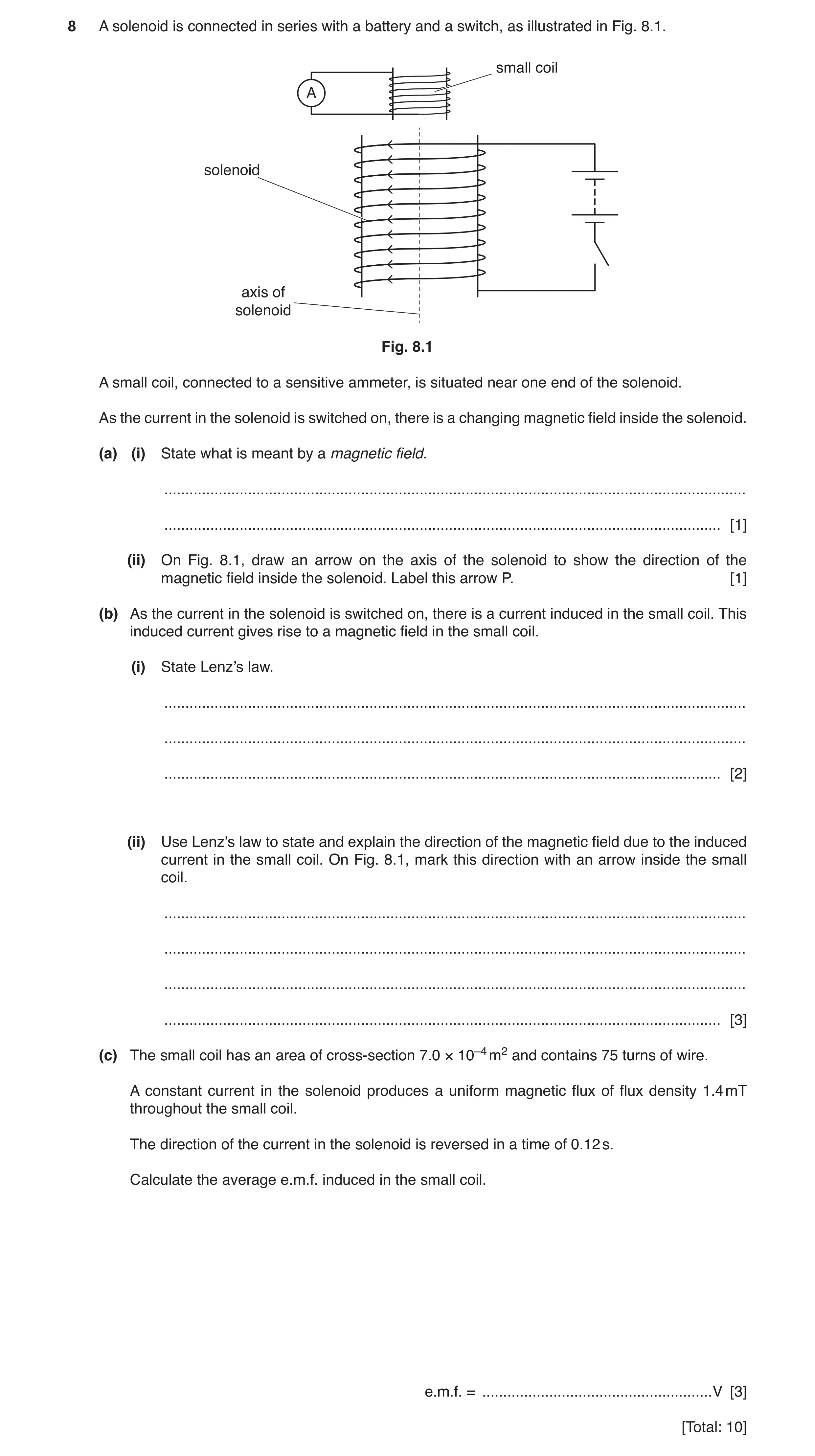
 11 / 48
 12 / 48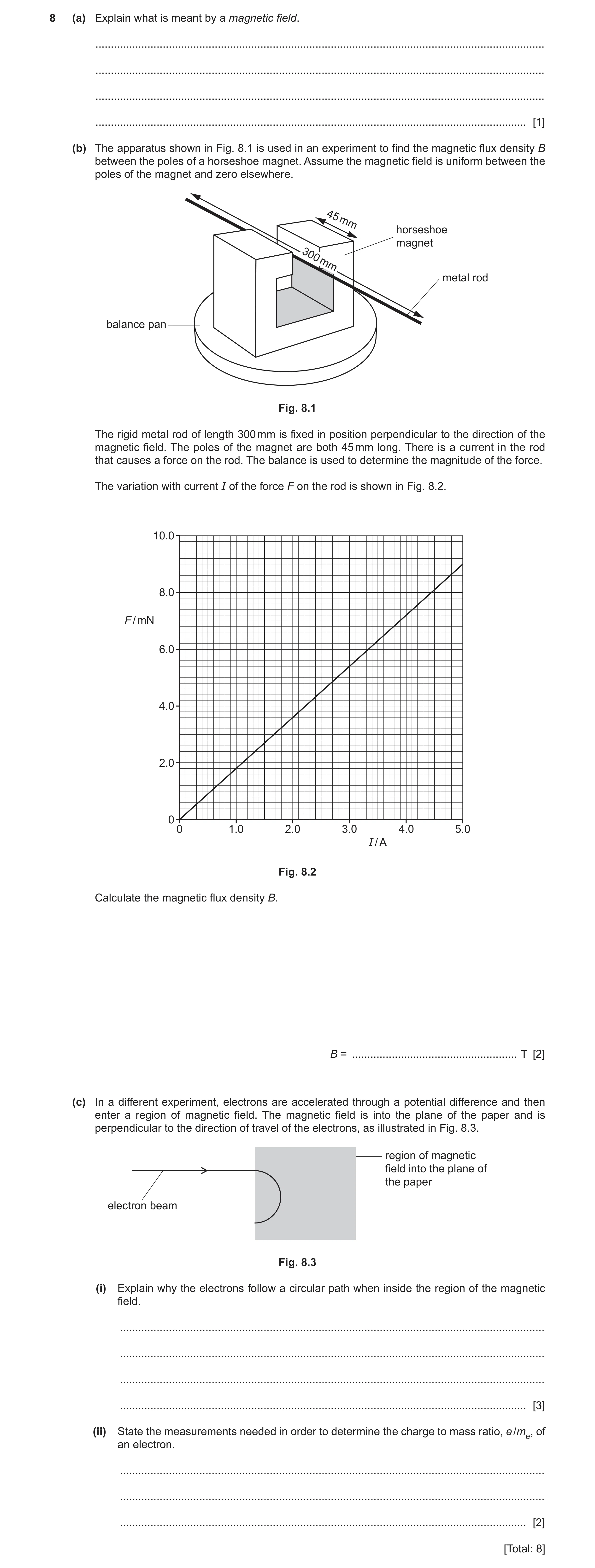
 9
9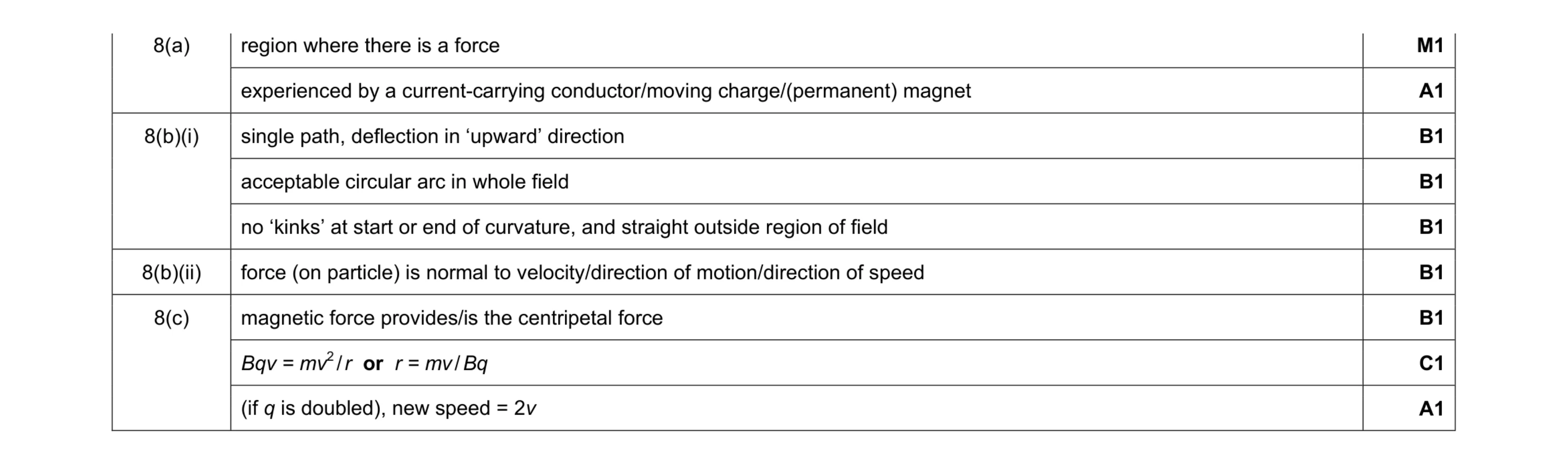 9
9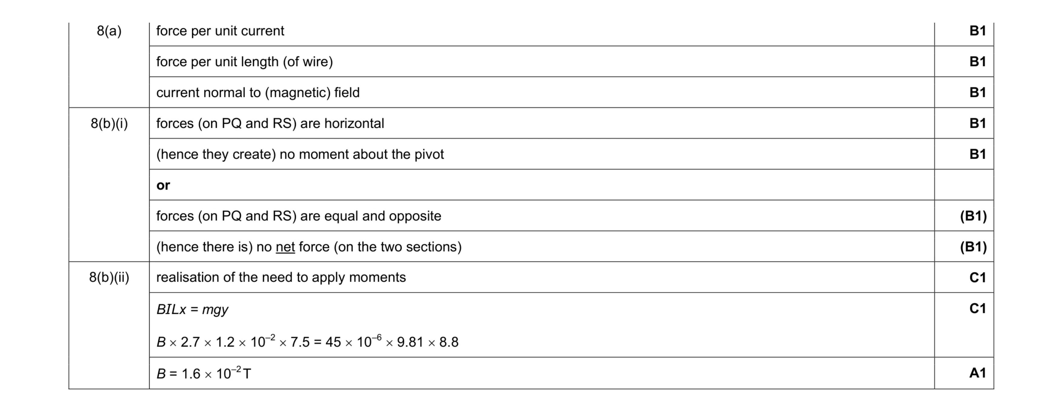 8
8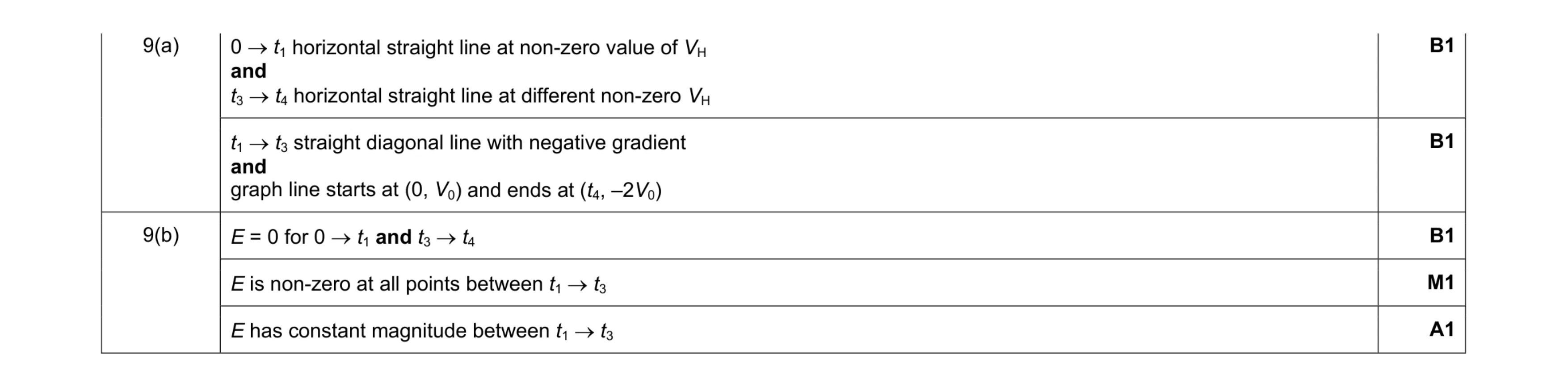 5
5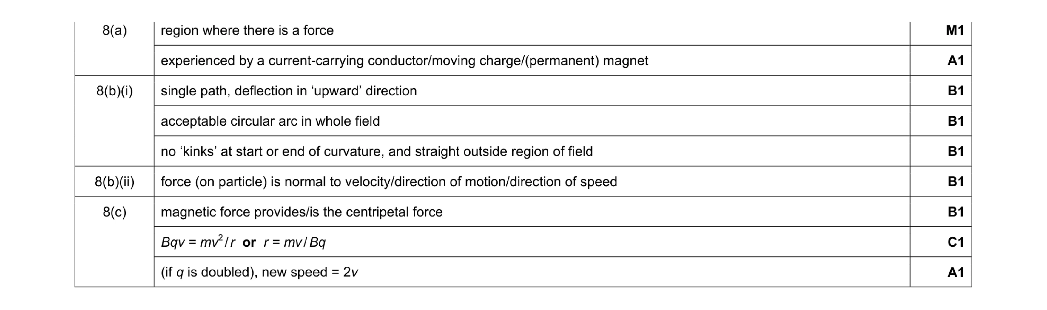 9
9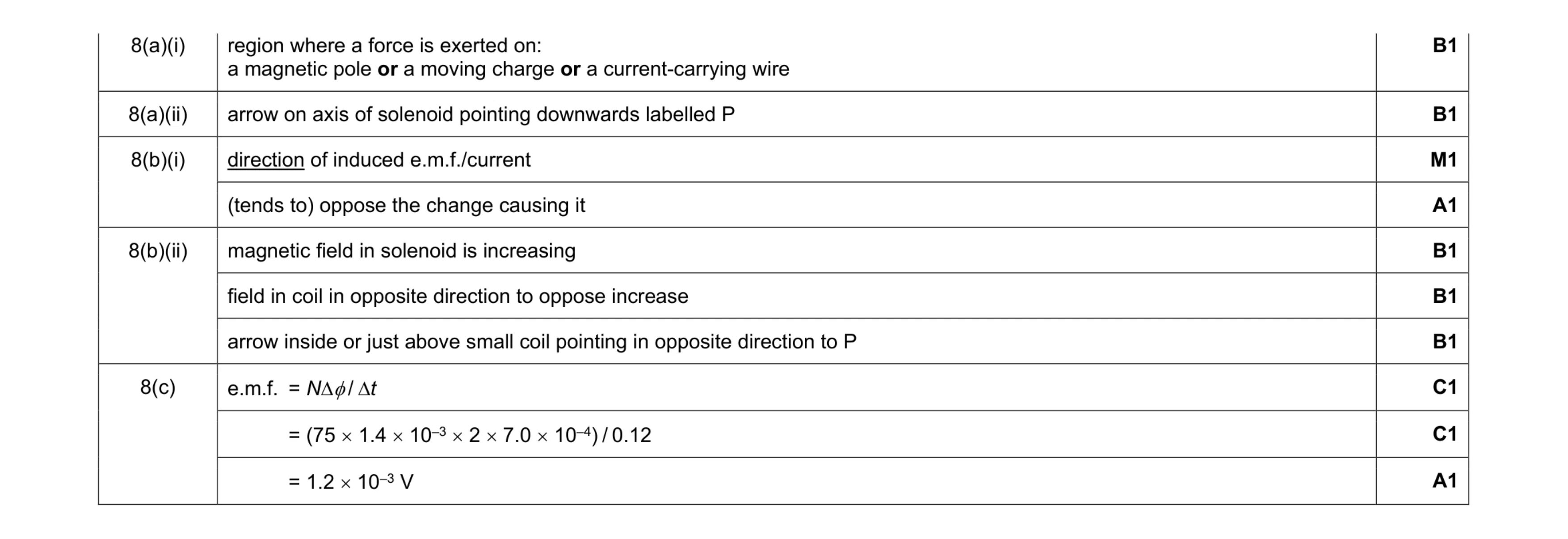 10
10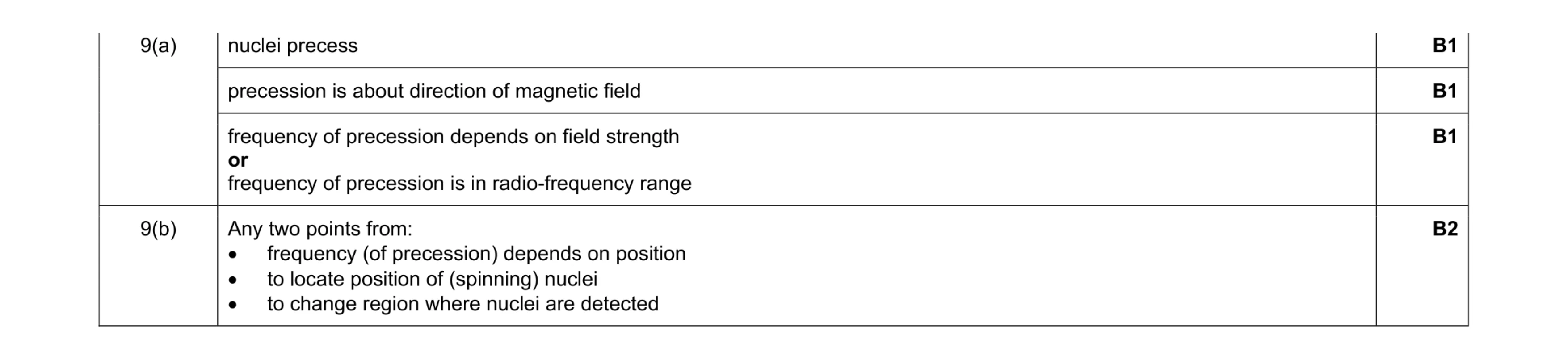 5
5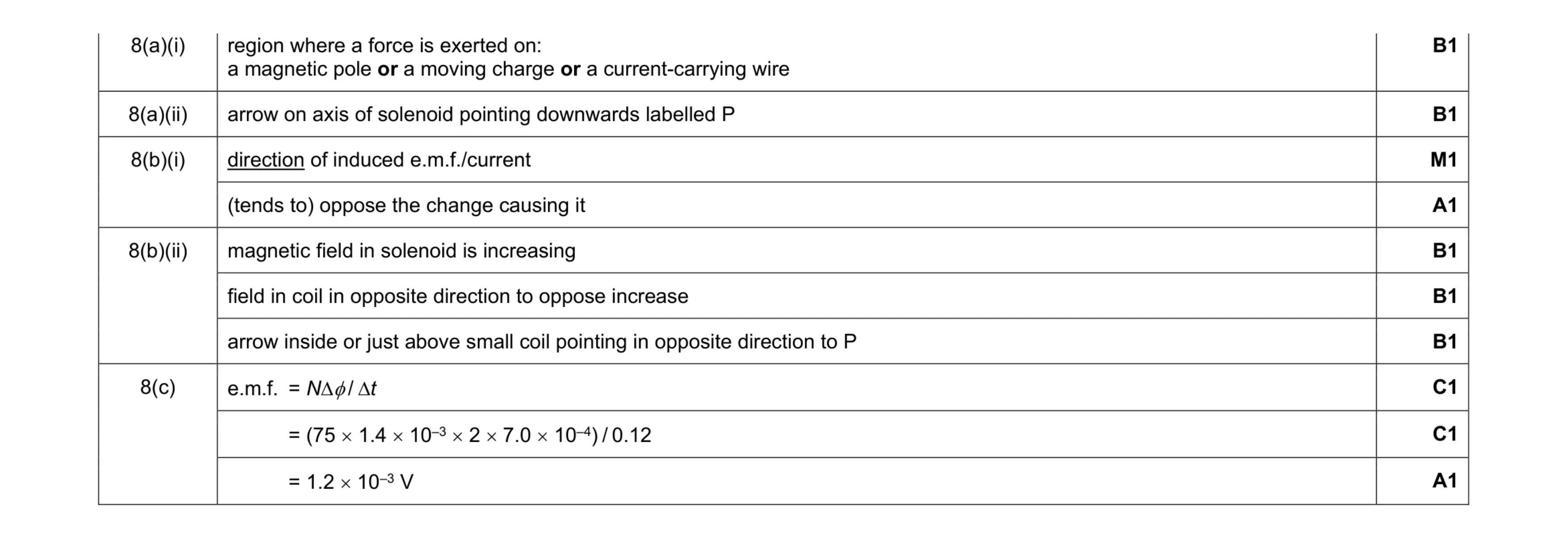 10
10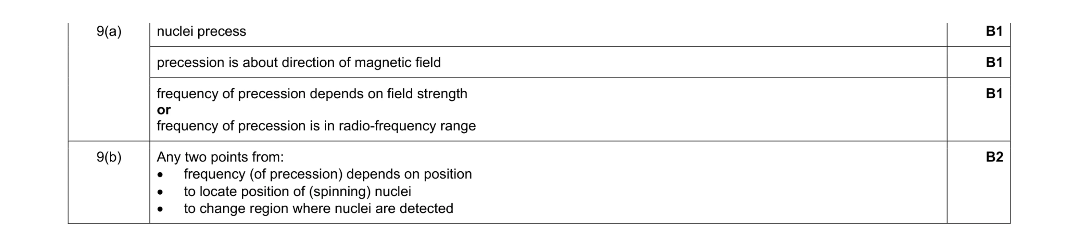 5
5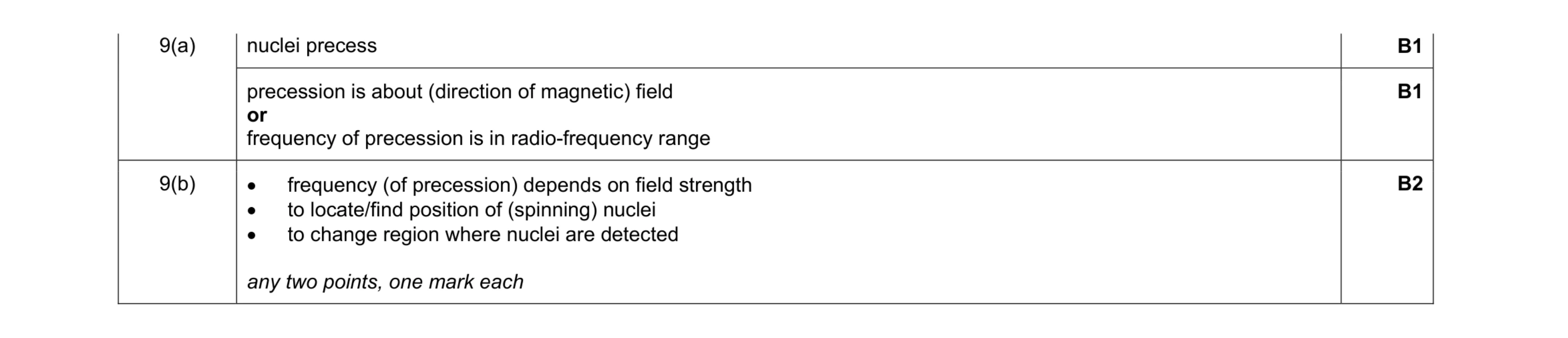 4
4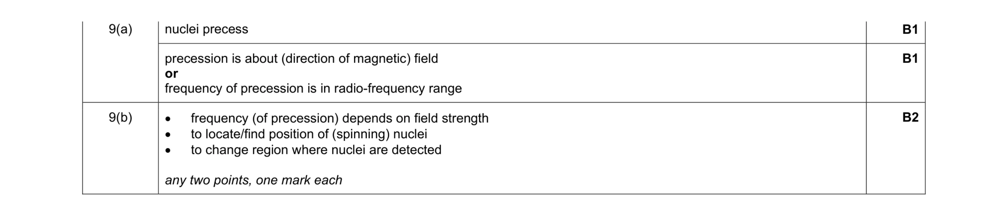 4
4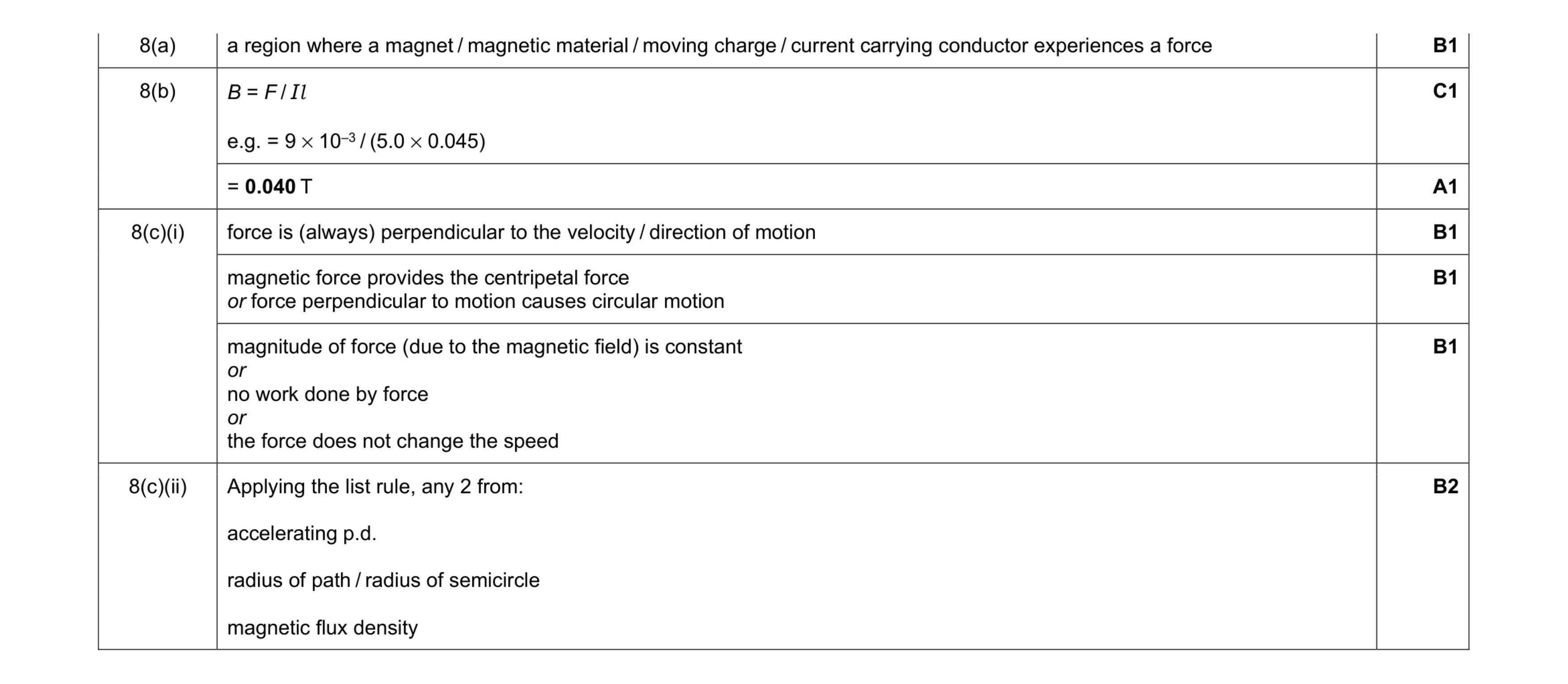 8
8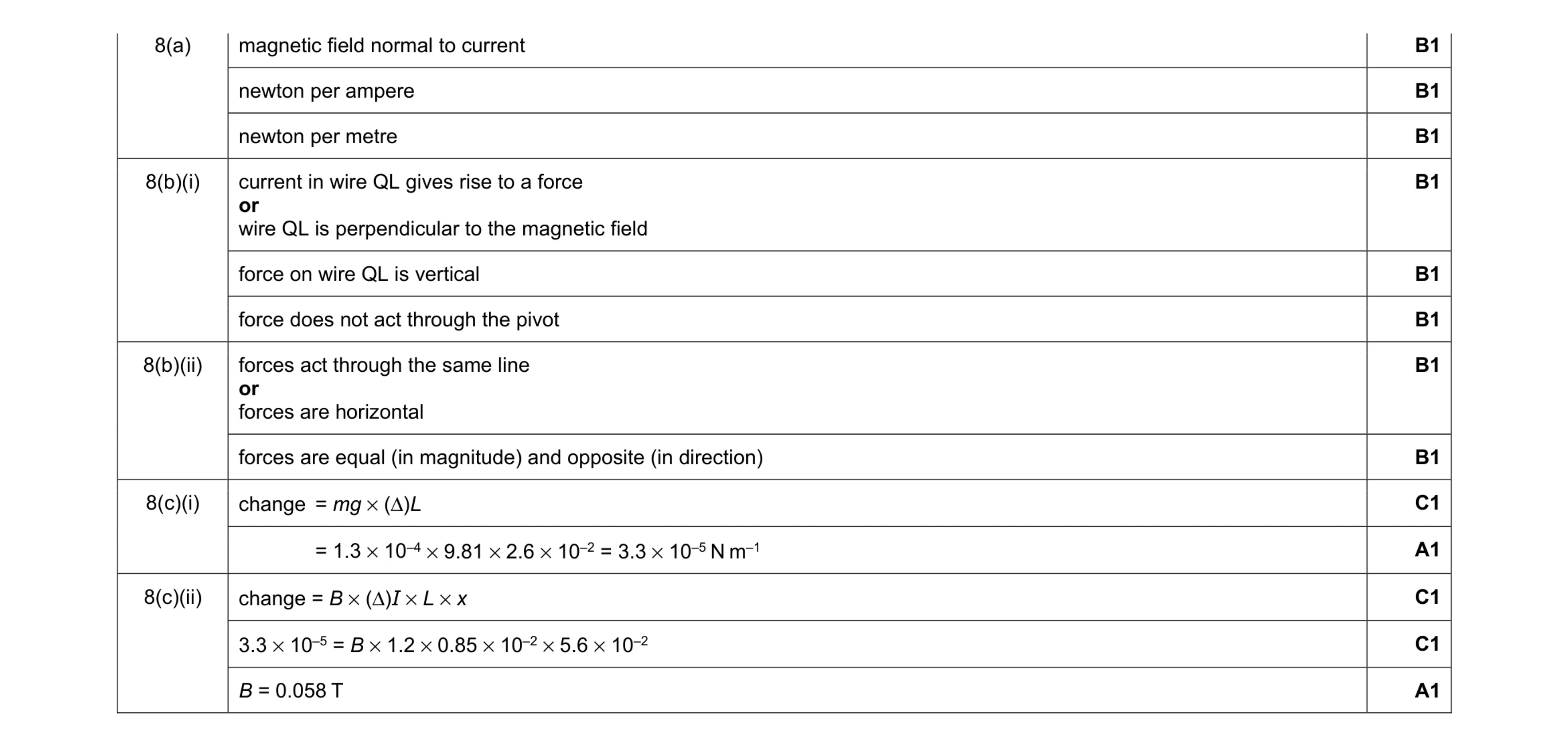 13
13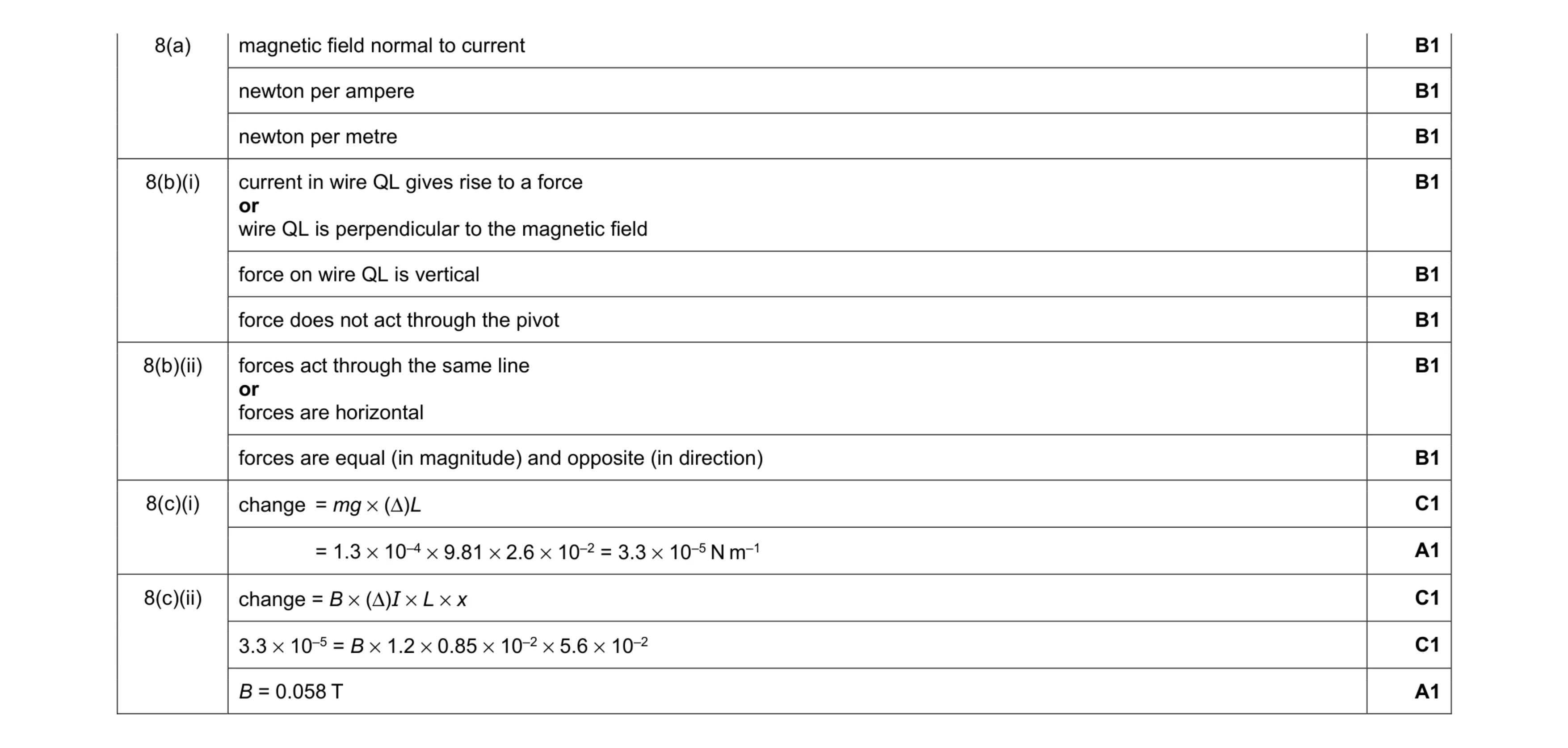 13
13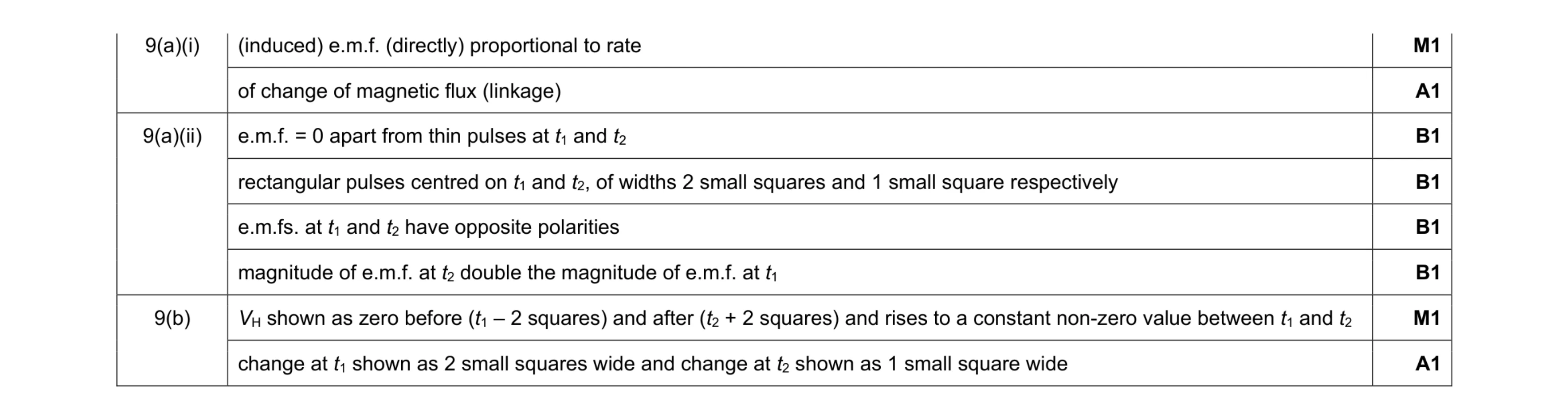 8
8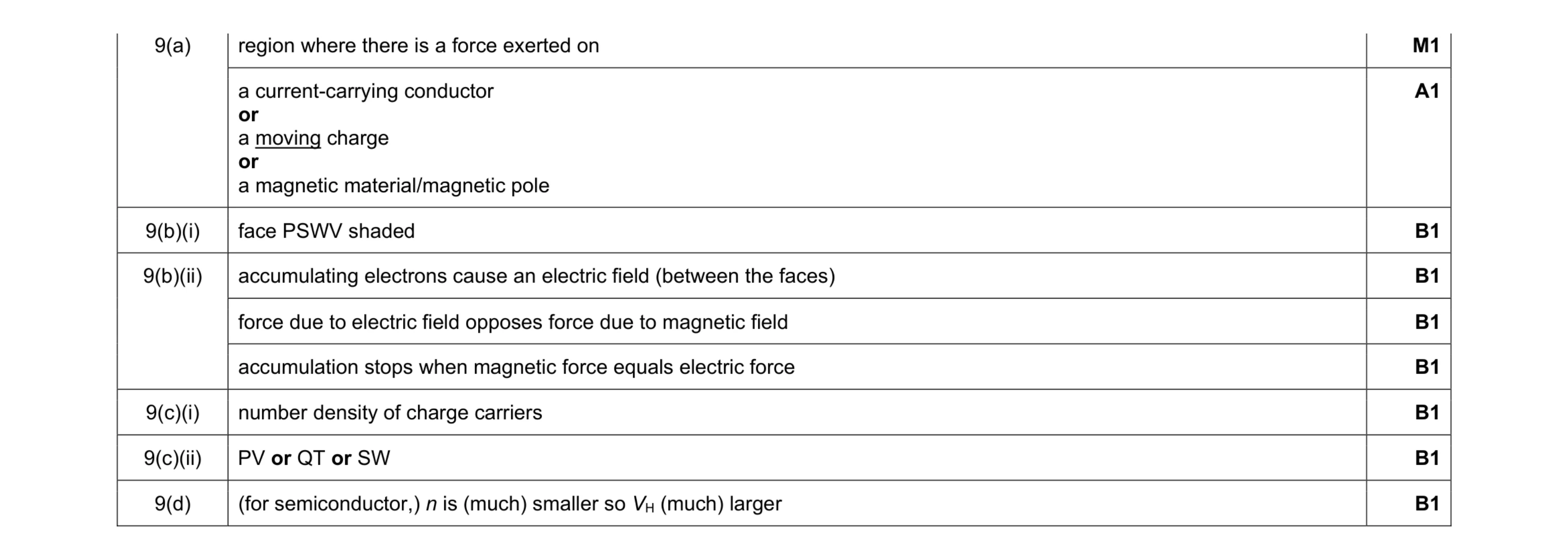 9
9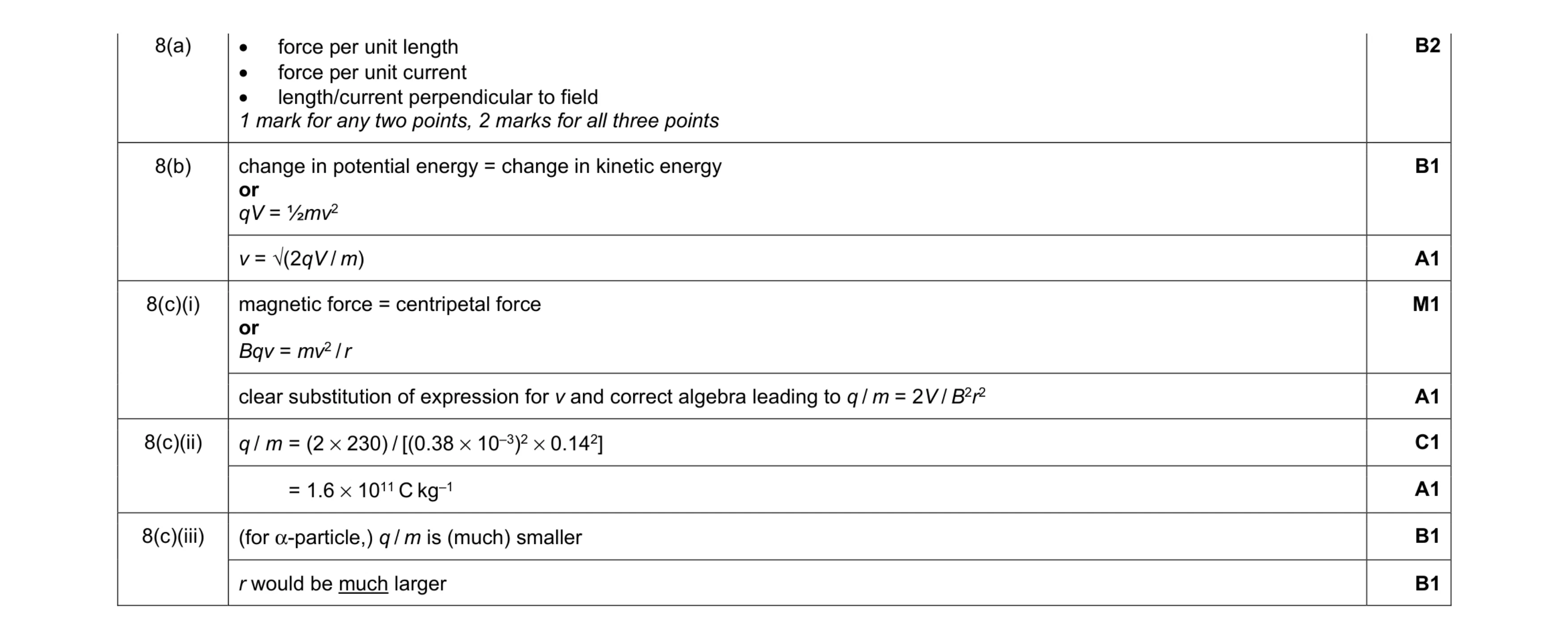 10
10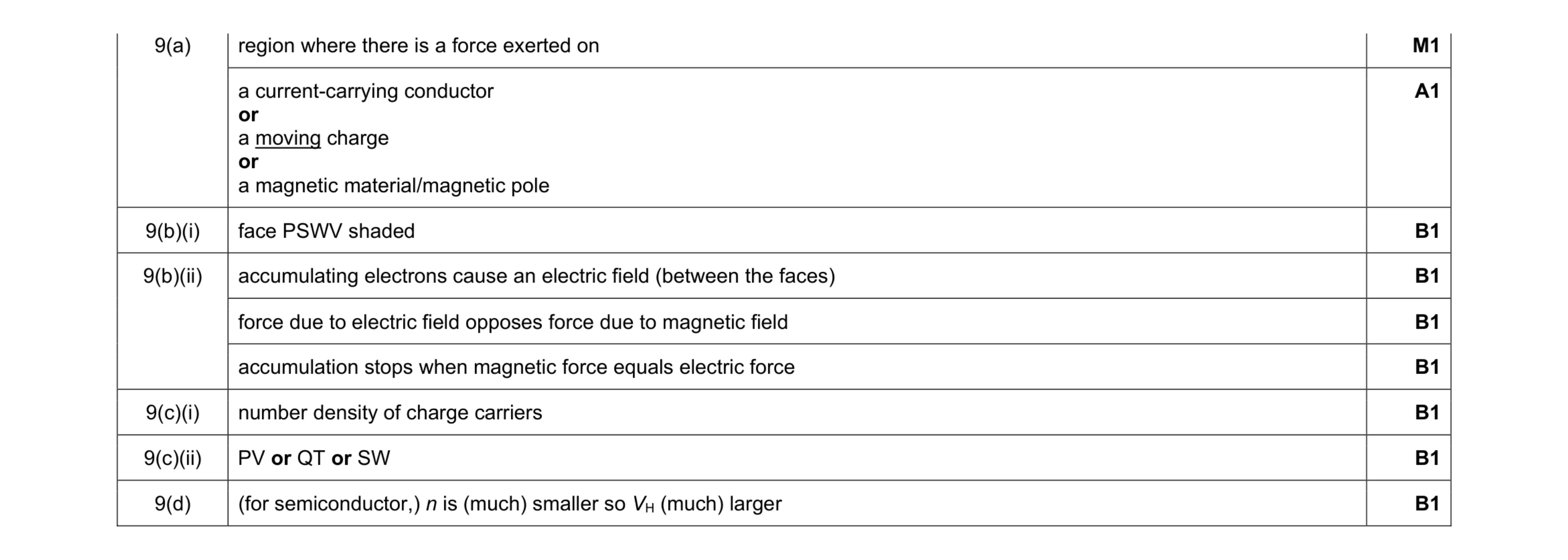 9
9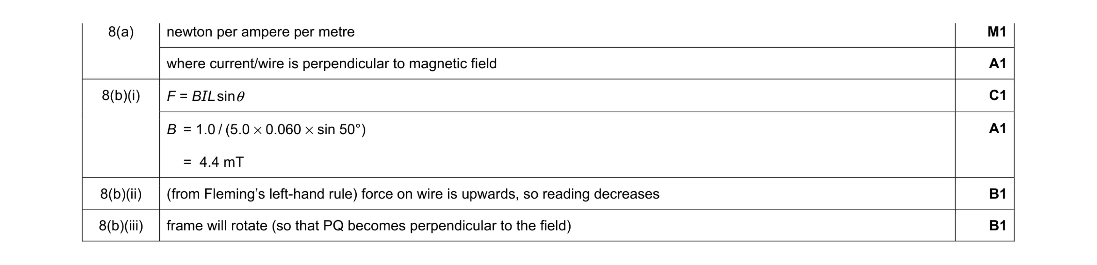 6
6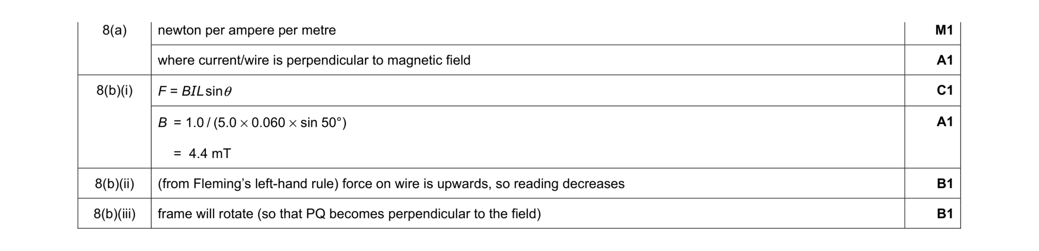 6
6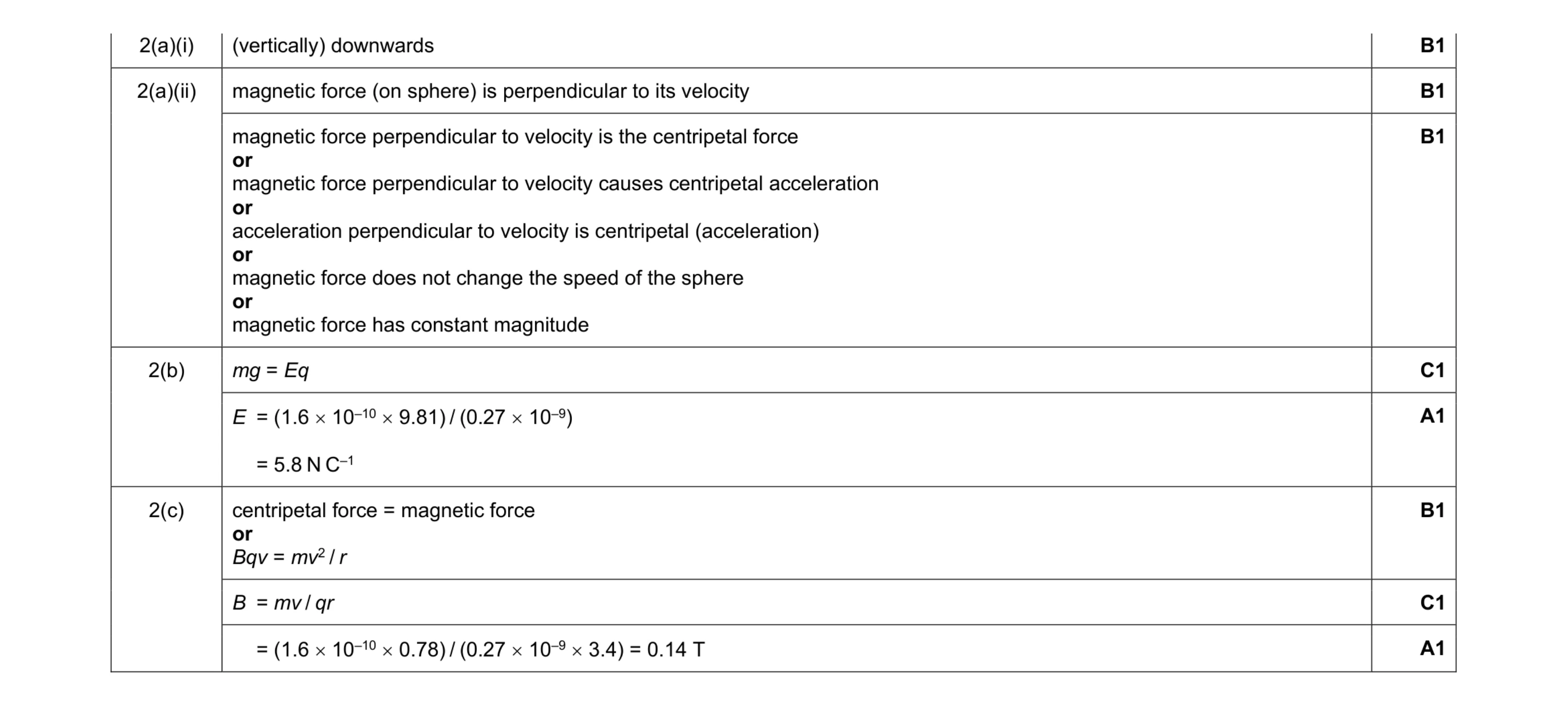 8
8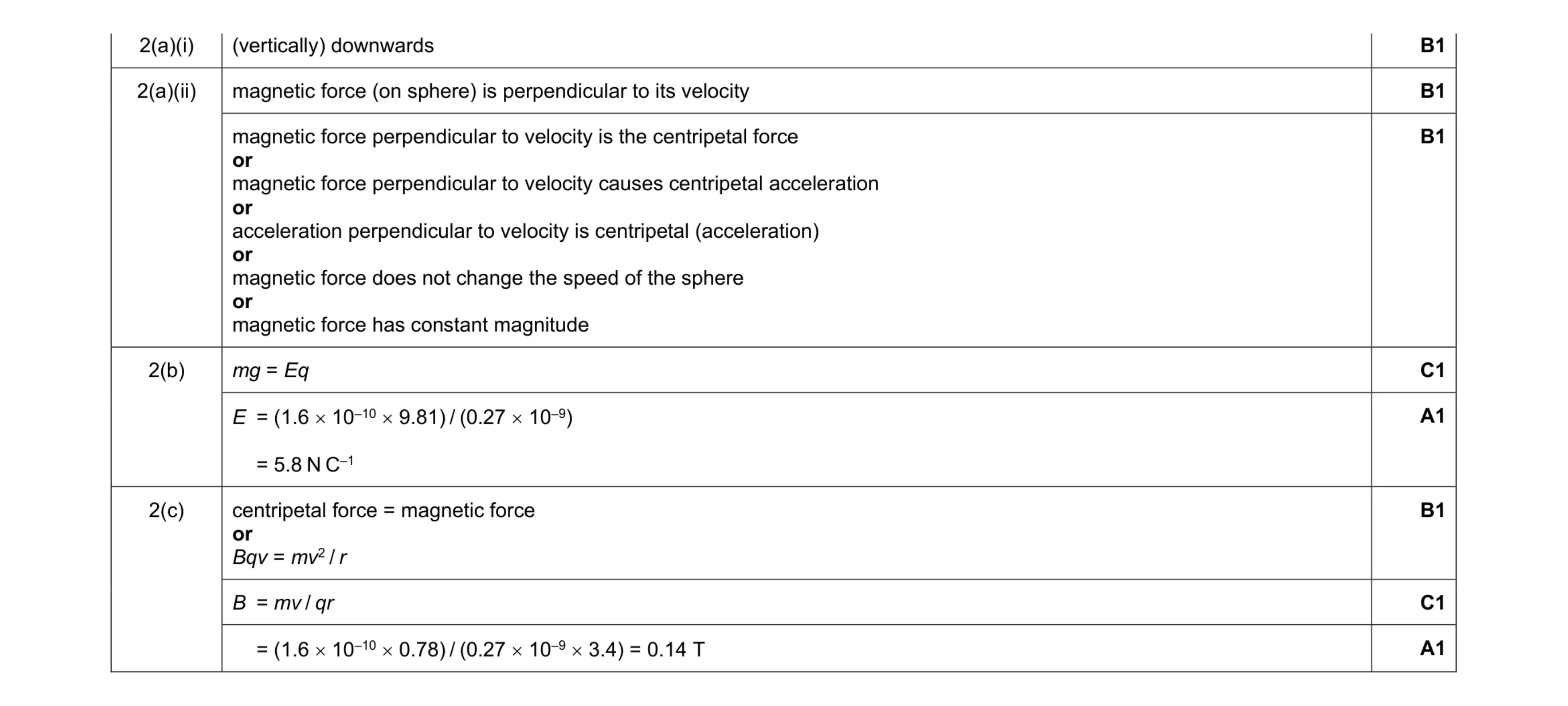 8
8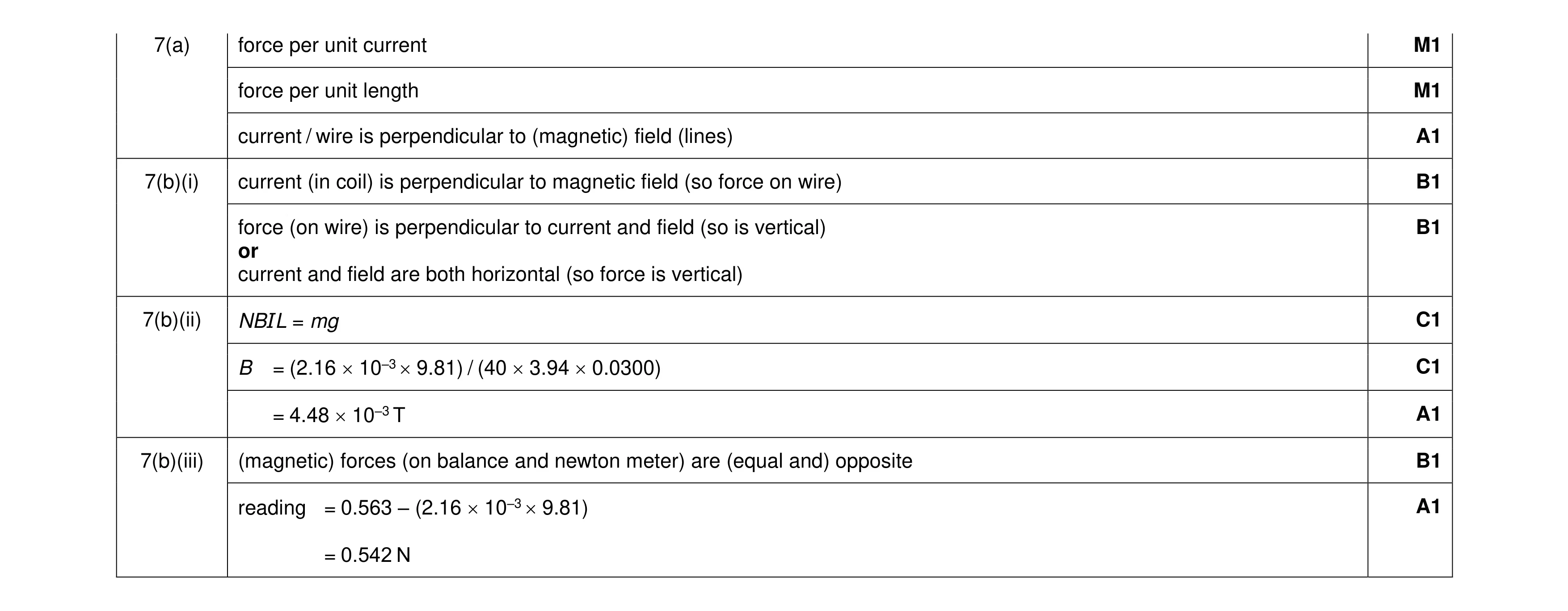 10
10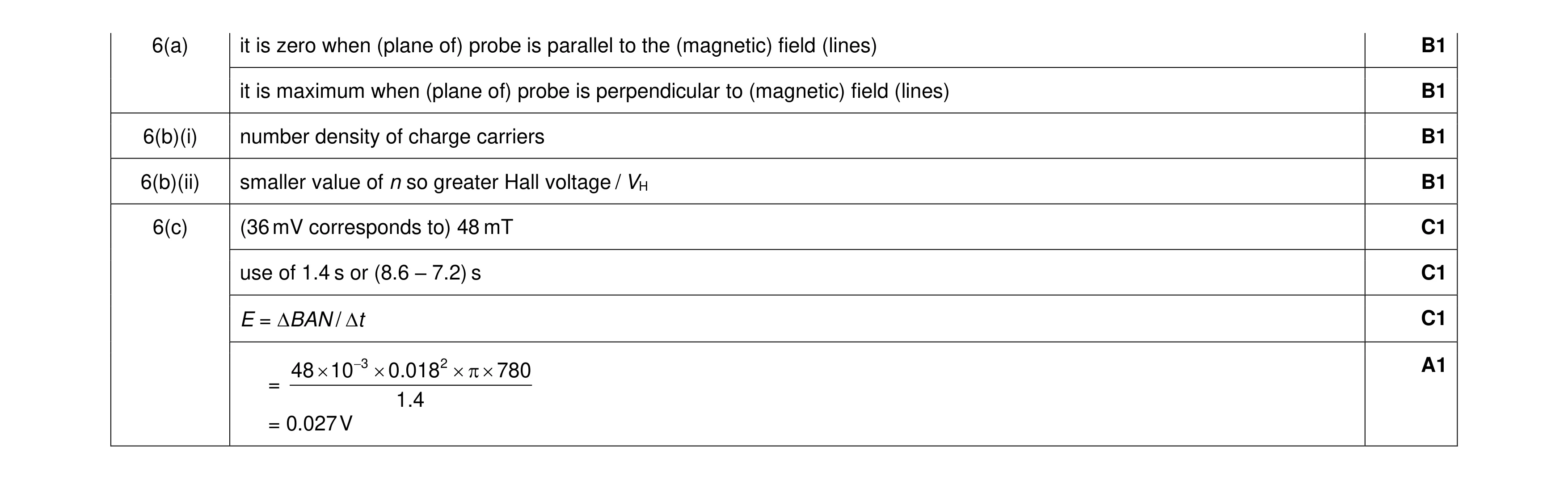 8
8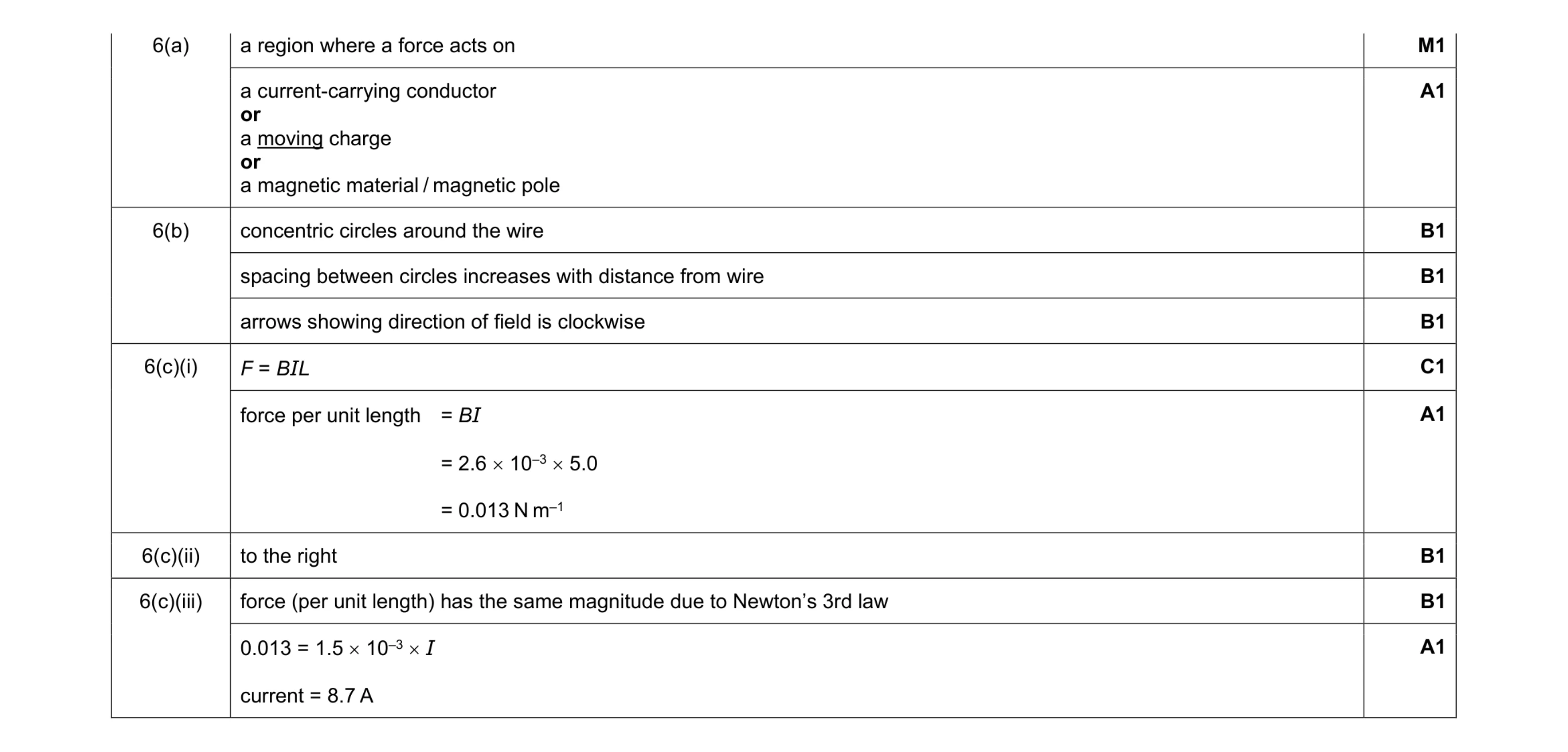 10
10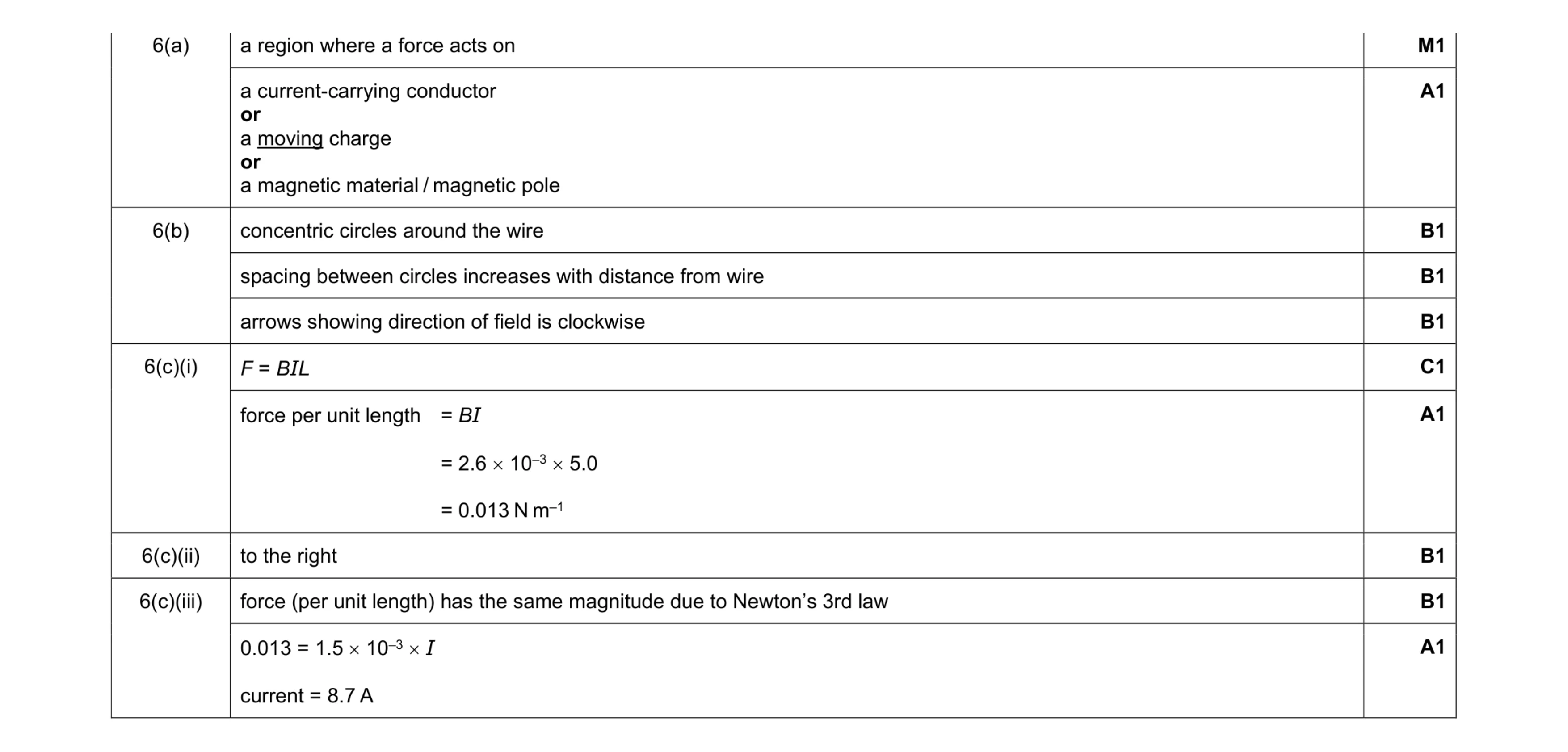 10
10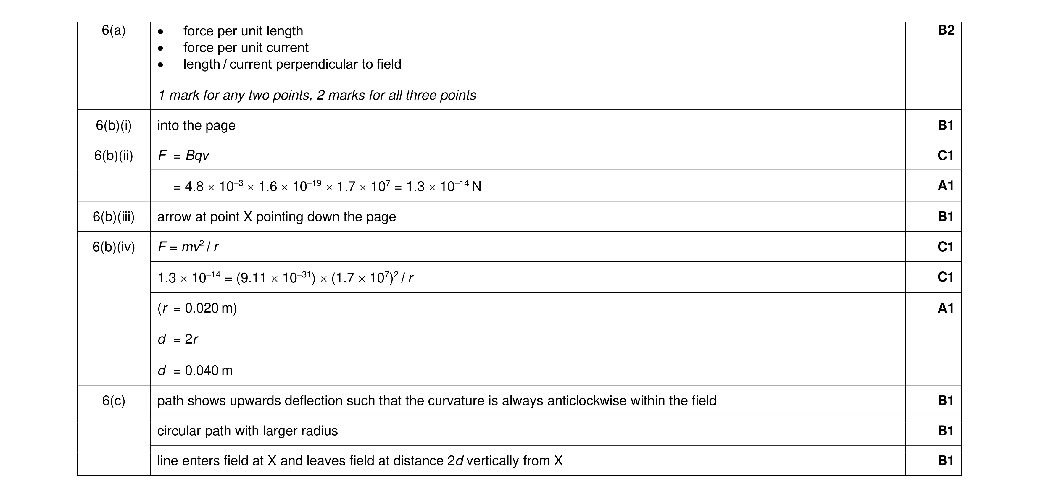 12
12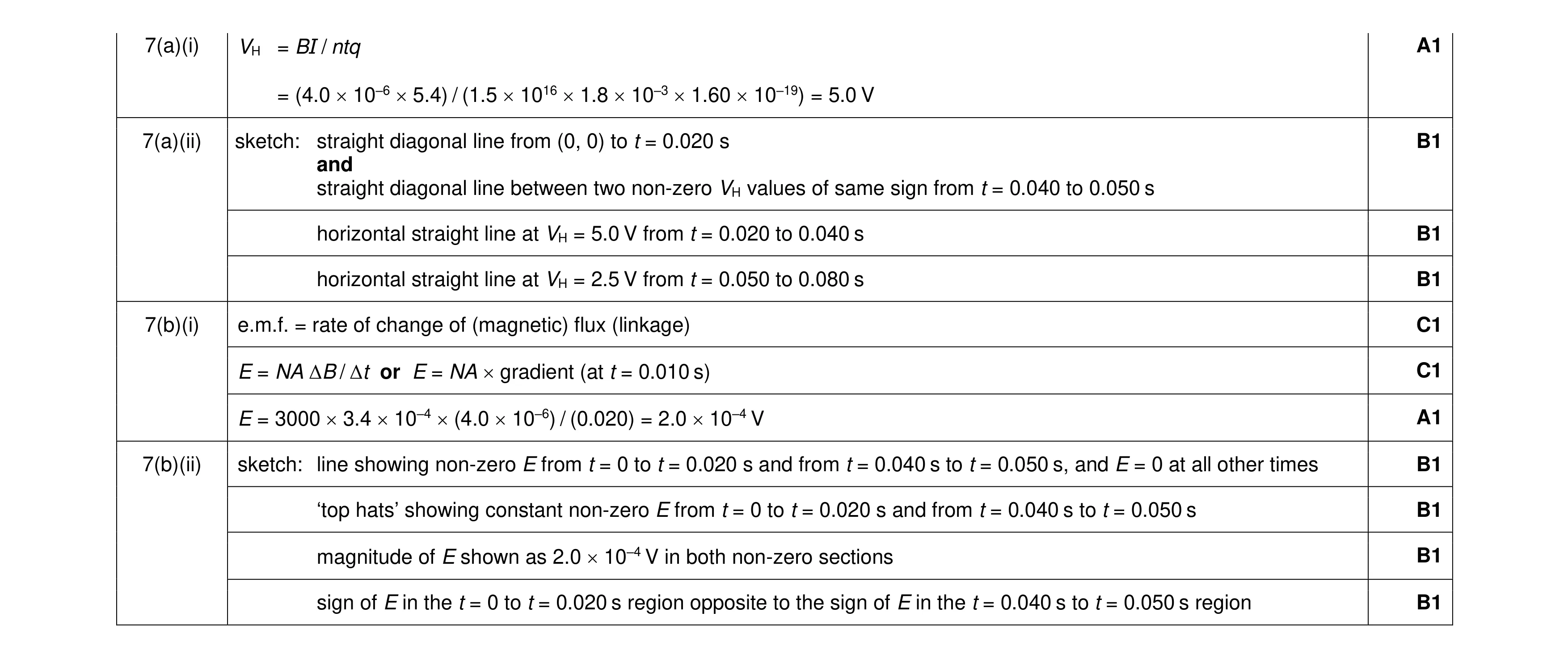 11
11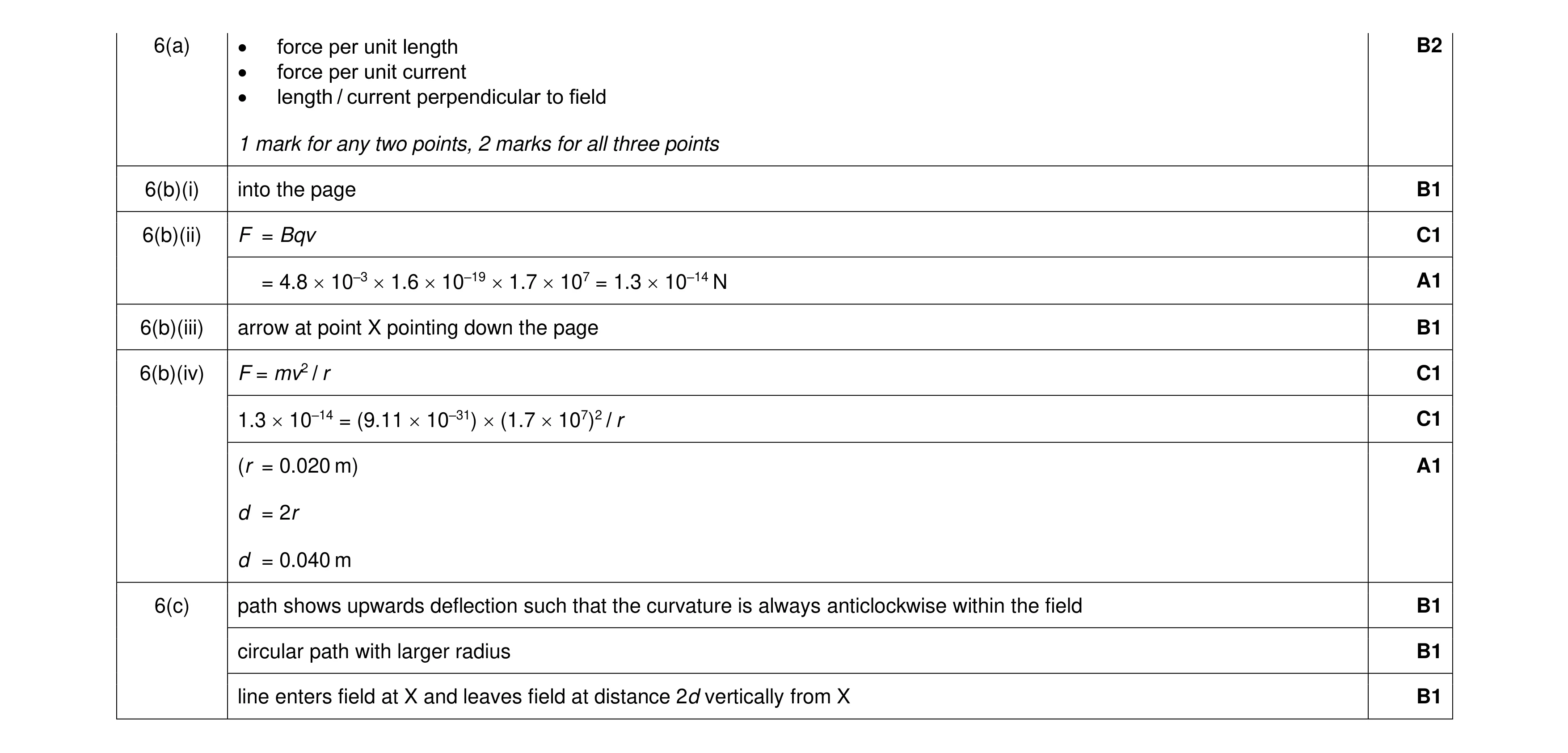 12
12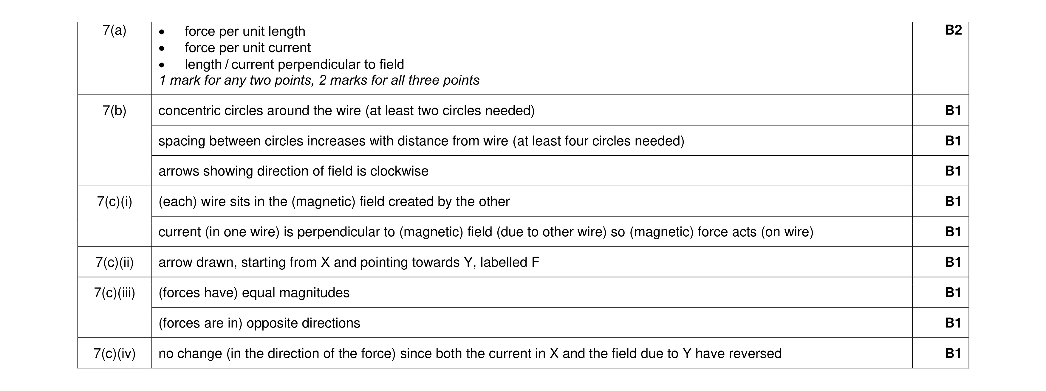 11
11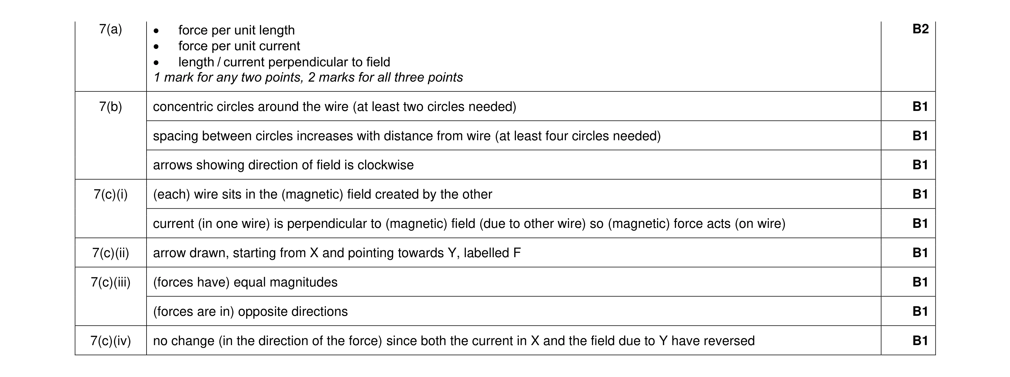 11
11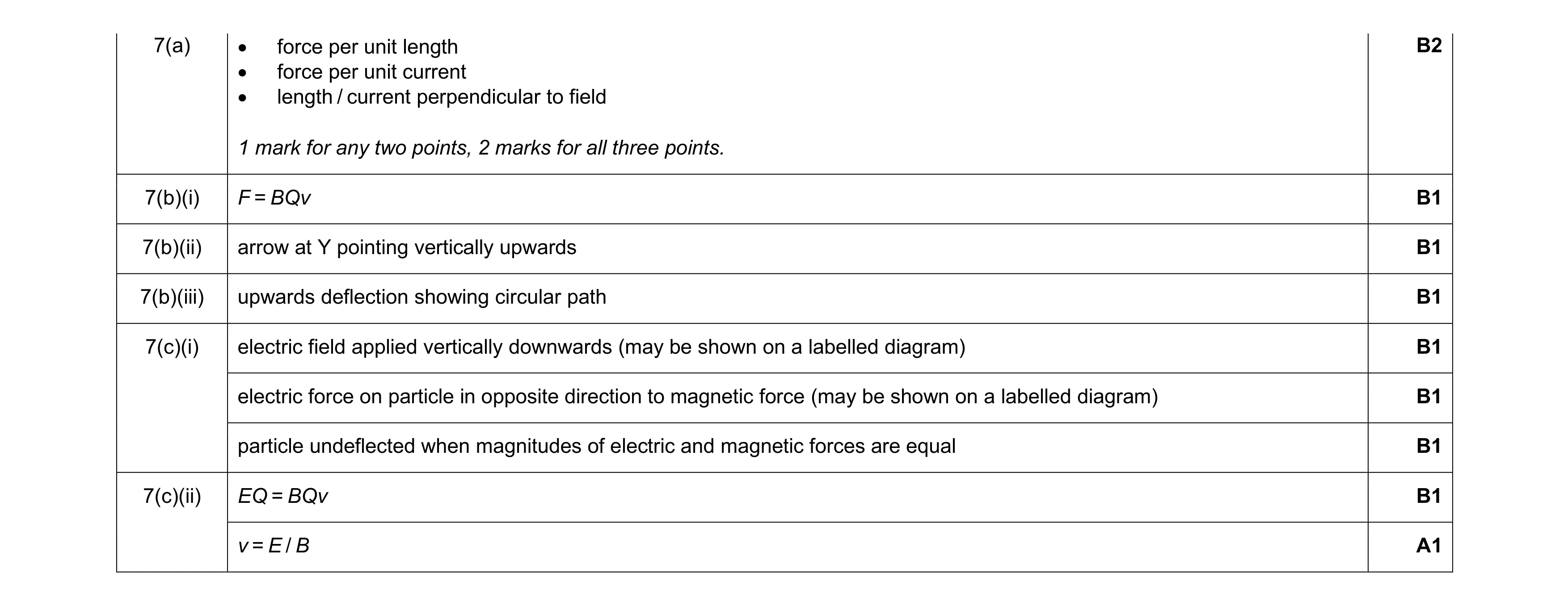 10
10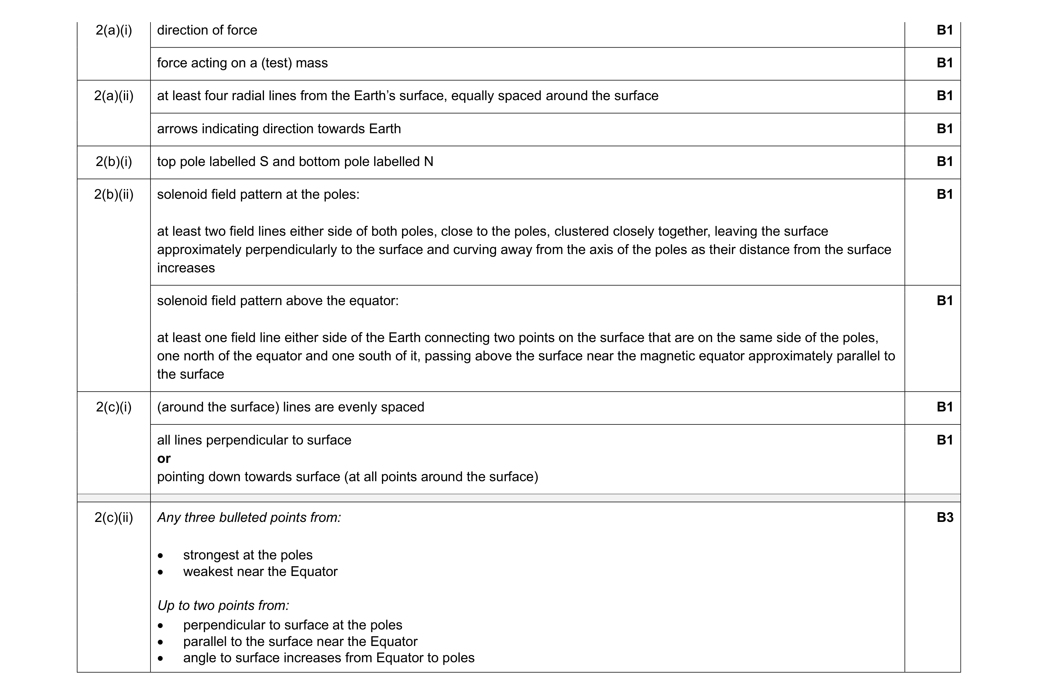 12
12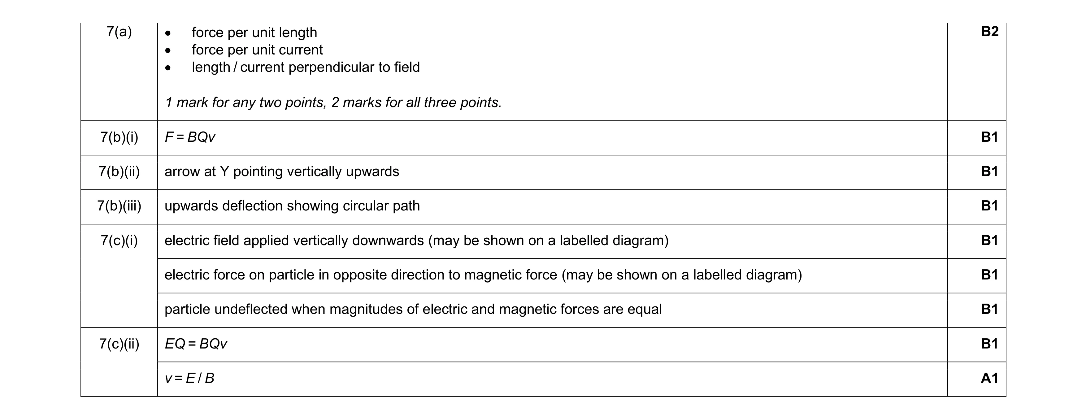 10
10