Questions as text
Q1 · A ground station on Earth transmits a signal of frequency 14 GHz and power 18 kW towards… 9702/41 May/June 2010
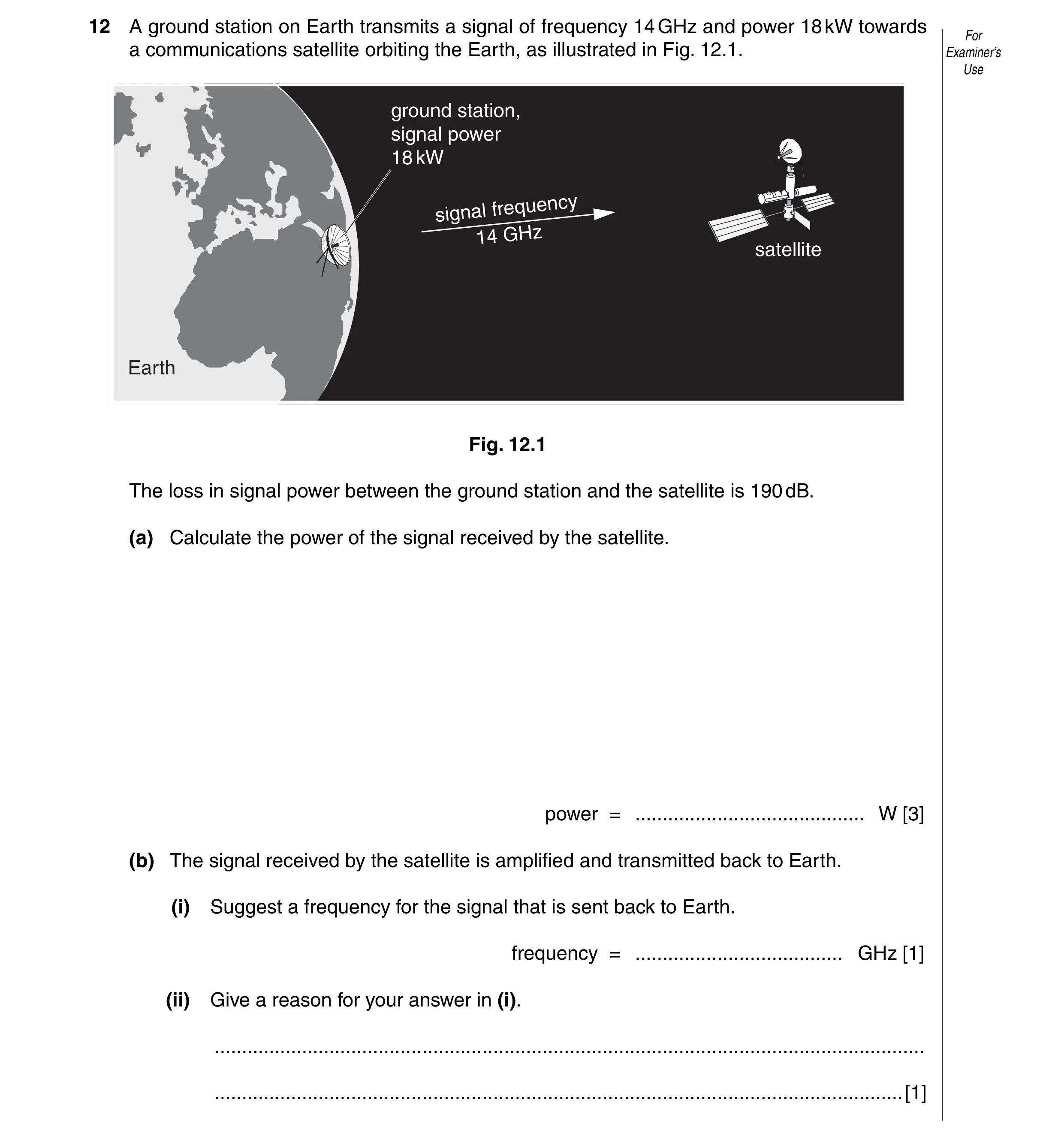
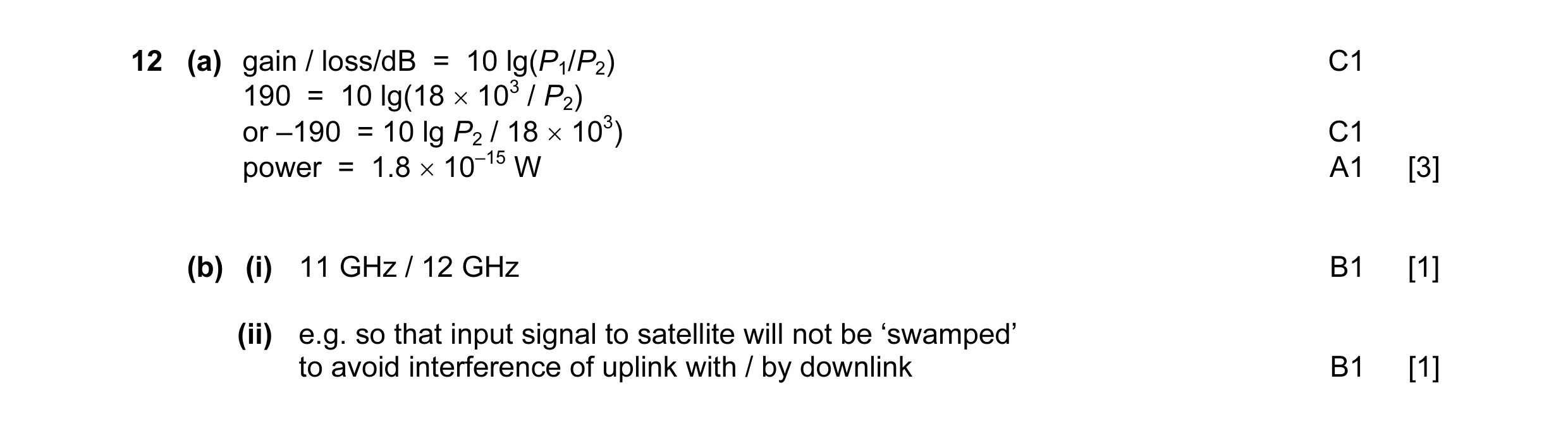
12 A ground station on Earth transmits a signal of frequency 14 GHz and power 18 kW towards For a communications satellite orbiting the Earth, as illustrated in Fig. 12.1. Examiner’s Use ground station, signal power 18 kW frequency signal 14 GHz satellite Earth Fig. 12.1 The loss in signal power between the ground station and the satellite is 190 dB. (a) Calculate the power of the signal received by the satellite. power = … W [3] (b) The signal received by the satellite is amplified and transmitted back to Earth. (i) Suggest a frequency for the signal that is sent back to Earth. frequency = … GHz [1] (ii) Give a reason for your answer in (i). … … [1]
5 marks
Mark scheme: 12 (a) gain / loss/dB = 10 lg(P1/P2) C1 190 = 10 lg(18 × 103 / P2) or –190 = 10 lg P2 / 18 × 103) C1 power = 1.8 × 10⁻¹⁵ W A1 [3] (b) (i) 11 GHz / 12 GHz B1 [1] (ii) e.g. so that input signal to satellite will not be ‘swamped’ to avoid interference of uplink with / by downlink B1 [1]
This question in 9702/41 May/June 2010
Q2 · Explain what is meant by the root-mean-square (r.m.s.) value of an alternating voltage 9702/42 May/June 2010
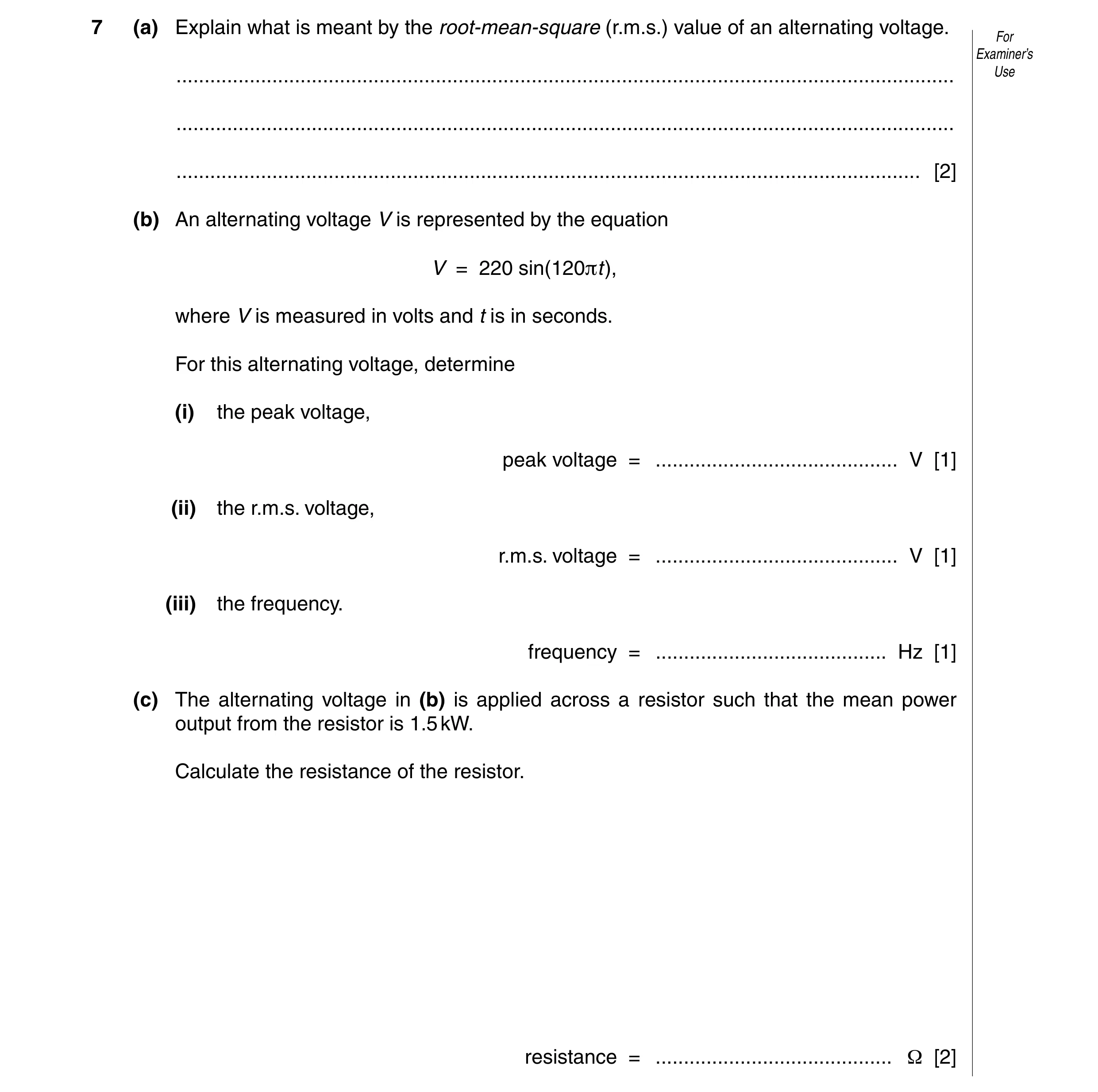
7 (a) Explain what is meant by the root-mean-square (r.m.s.) value of an alternating voltage. For Examiner’s … Use … … [2] (b) An alternating voltage V is represented by the equation V = 220 sin(120πt), where V is measured in volts and t is in seconds. For this alternating voltage, determine (i) the peak voltage, peak voltage = … V [1] (ii) the r.m.s. voltage, r.m.s. voltage = … V [1] (iii) the frequency. frequency = … Hz [1] (c) The alternating voltage in (b) is applied across a resistor such that the mean power output from the resistor is 1.5 kW. Calculate the resistance of the resistor. resistance = … Ω [2]
7 marks
Mark scheme: 7 (a) either the value of steady / constant voltage M1 that produces same power (in a resistor) as the alternating voltage A1 [2] or if alternating voltage is squared and averaged (M1) the r.m.s. value is the square root of this averaged value (A1) (b) (i) 220 V A1 [1] (ii) 156 V A1 [1] (iii) 60 Hz A1 [1] (c) power = Vrms2 / R C1 R = 1562 / 1500 = 16 Ω A1 [2] 6 23
This question in 9702/42 May/June 2010
Q3 · A telephone link between two towns is to be provided using an optic fibre 9702/42 May/June 2010
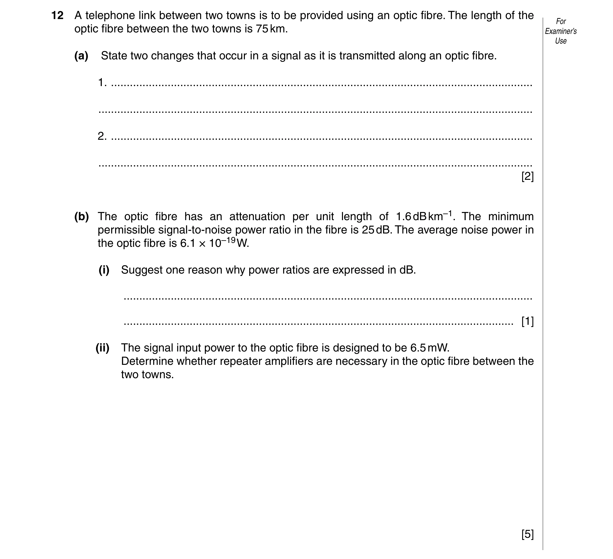
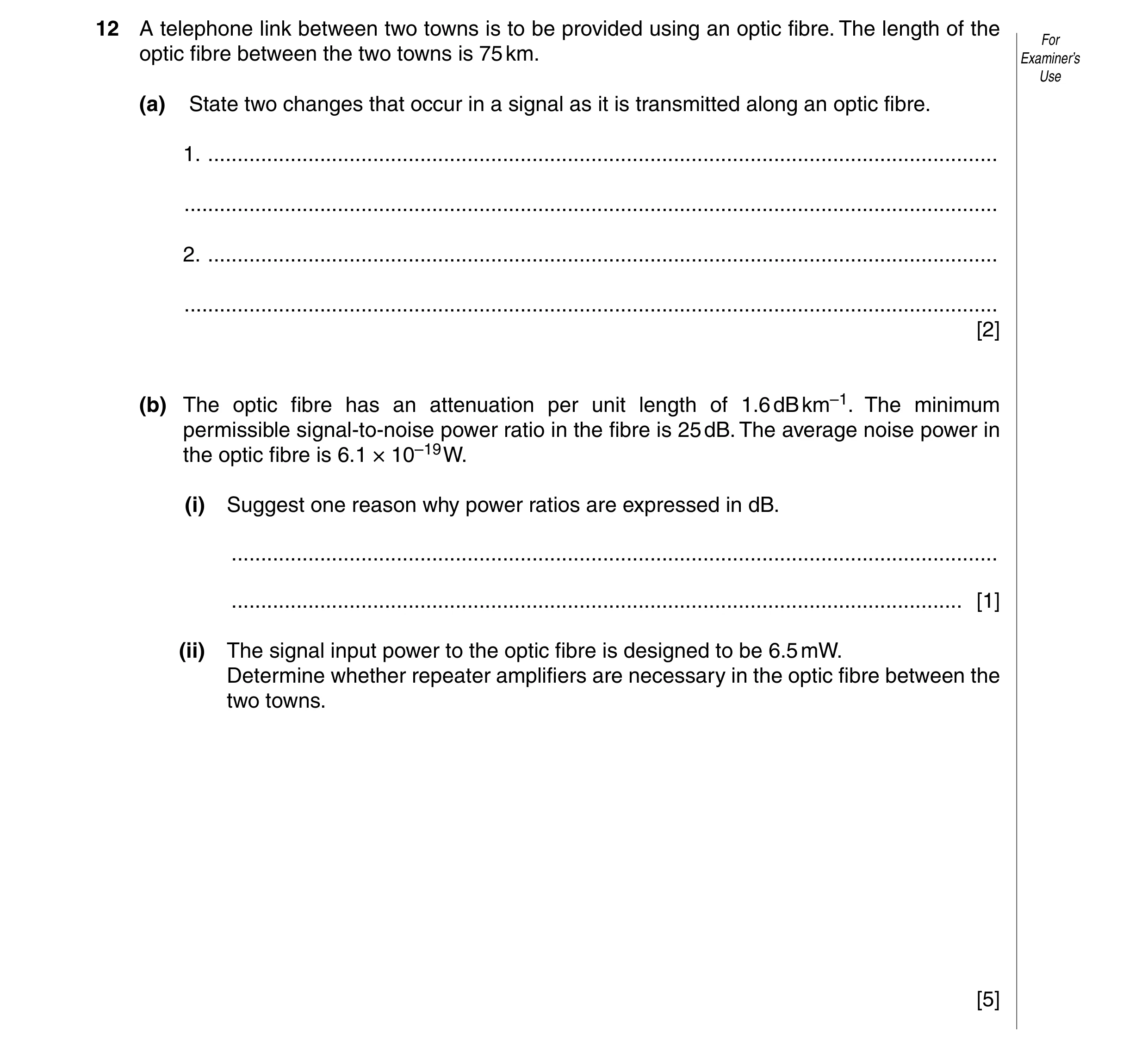
12 A telephone link between two towns is to be provided using an optic fibre. The length of the For optic fibre between the two towns is 75 km. Examiner’s Use (a) State two changes that occur in a signal as it is transmitted along an optic fibre. 1. … … 2. … … [2] (b) The optic fibre has an attenuation per unit length of 1.6 dB km–1. The minimum permissible signal-to-noise power ratio in the fibre is 25 dB. The average noise power in the optic fibre is 6.1 × 10⁻¹⁹ W. (i) Suggest one reason why power ratios are expressed in dB. … … [1] (ii) The signal input power to the optic fibre is designed to be 6.5 mW. Determine whether repeater amplifiers are necessary in the optic fibre between the two towns. [5]
8 marks
Mark scheme: 12 (a) signal becomes distorted / noisy B1 signal loses power / energy / intensity / is attenuated B1 [2] (b) (i) either numbers involved are smaller / more manageable / cover wider range or calculations involve addition & subtraction rather than multiplication and division B1 [1] (ii) 25 = 10 lg(Pmin / (6.1 × 10⁻¹⁹)) C1 minimum signal power = 1.93 × 10⁻¹⁶ W C1 signal loss = 10 lg(6.5 × 10⁻³)/(1.93 × 10–16) = 135 dB C1 maximum cable length = 135 / 1.6 C1 = 85 km so no repeaters necessary A1 [5]
This question in 9702/42 May/June 2010
Q4 · Explain what is meant by the root-mean-square (r.m.s.) value of an alternating voltage 9702/43 May/June 2010
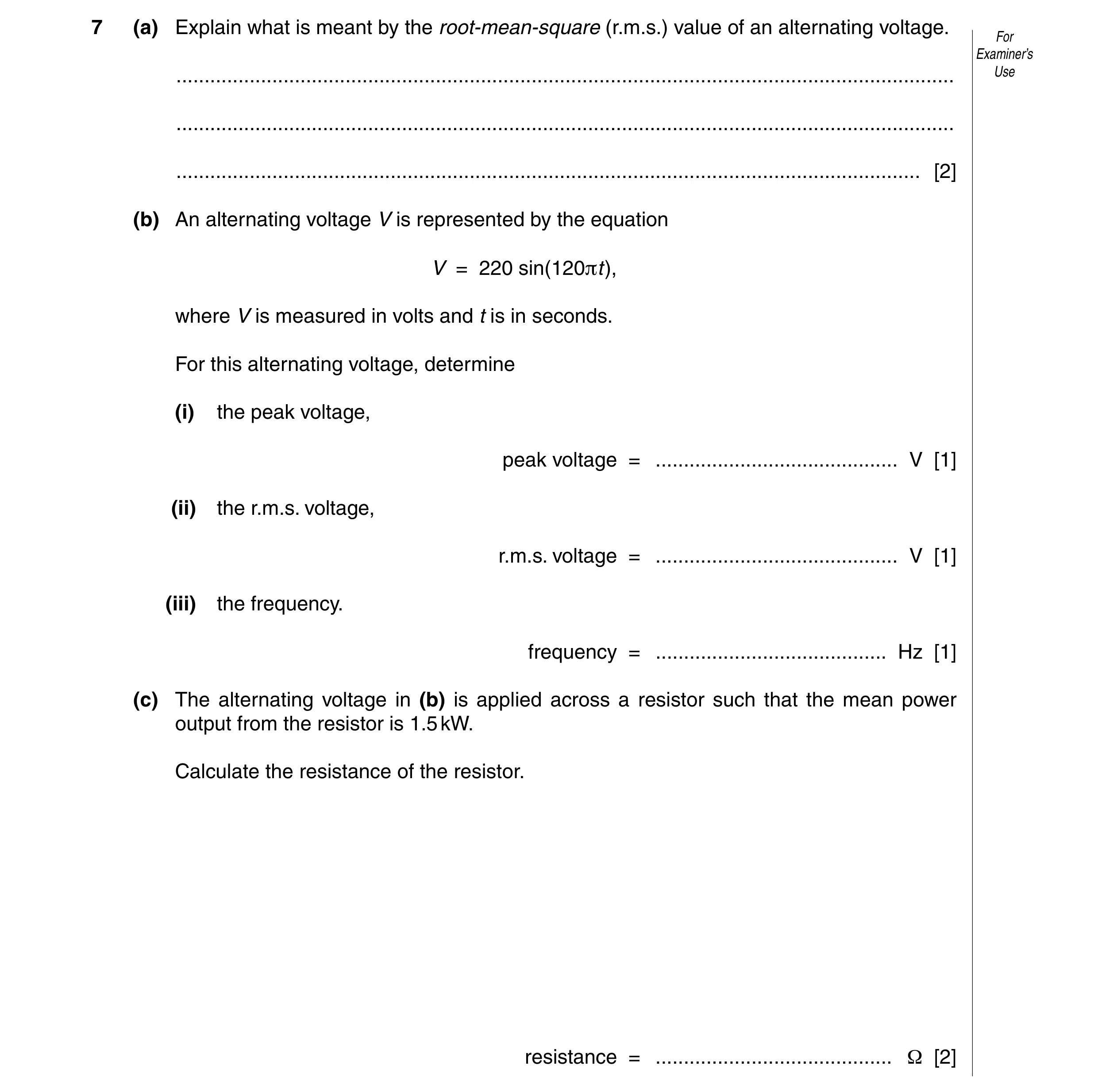
7 (a) Explain what is meant by the root-mean-square (r.m.s.) value of an alternating voltage. For Examiner’s … Use … … [2] (b) An alternating voltage V is represented by the equation V = 220 sin(120πt), where V is measured in volts and t is in seconds. For this alternating voltage, determine (i) the peak voltage, peak voltage = … V [1] (ii) the r.m.s. voltage, r.m.s. voltage = … V [1] (iii) the frequency. frequency = … Hz [1] (c) The alternating voltage in (b) is applied across a resistor such that the mean power output from the resistor is 1.5 kW. Calculate the resistance of the resistor. resistance = … Ω [2]
7 marks
Mark scheme: 7 (a) either the value of steady / constant voltage M1 that produces same power (in a resistor) as the alternating voltage A1 [2] or if alternating voltage is squared and averaged (M1) the r.m.s. value is the square root of this averaged value (A1) (b) (i) 220 V A1 [1] (ii) 156 V A1 [1] (iii) 60 Hz A1 [1] (c) power = Vrms2 / R C1 R = 1562 / 1500 = 16 Ω A1 [2] 6 23
This question in 9702/43 May/June 2010
Q5 · A telephone link between two towns is to be provided using an optic fibre 9702/43 May/June 2010
12 A telephone link between two towns is to be provided using an optic fibre. The length of the For optic fibre between the two towns is 75 km. Examiner’s Use (a) State two changes that occur in a signal as it is transmitted along an optic fibre. 1. … … 2. … … [2] (b) The optic fibre has an attenuation per unit length of 1.6 dB km–1. The minimum permissible signal-to-noise power ratio in the fibre is 25 dB. The average noise power in the optic fibre is 6.1 × 10⁻¹⁹ W. (i) Suggest one reason why power ratios are expressed in dB. … … [1] (ii) The signal input power to the optic fibre is designed to be 6.5 mW. Determine whether repeater amplifiers are necessary in the optic fibre between the two towns. [5]
8 marks
Mark scheme: 12 (a) signal becomes distorted / noisy B1 signal loses power / energy / intensity / is attenuated B1 [2] (b) (i) either numbers involved are smaller / more manageable / cover wider range or calculations involve addition & subtraction rather than multiplication and division B1 [1] (ii) 25 = 10 lg(Pmin / (6.1 × 10⁻¹⁹)) C1 minimum signal power = 1.93 × 10⁻¹⁶ W C1 signal loss = 10 lg(6.5 × 10⁻³)/(1.93 × 10–16) = 135 dB C1 maximum cable length = 135 / 1.6 C1 = 85 km so no repeaters necessary A1 [5]
This question in 9702/43 May/June 2010
Q6 · The variation with time t of the current I in a resistor is shown in Fig 9702/43 Oct/Nov 2010
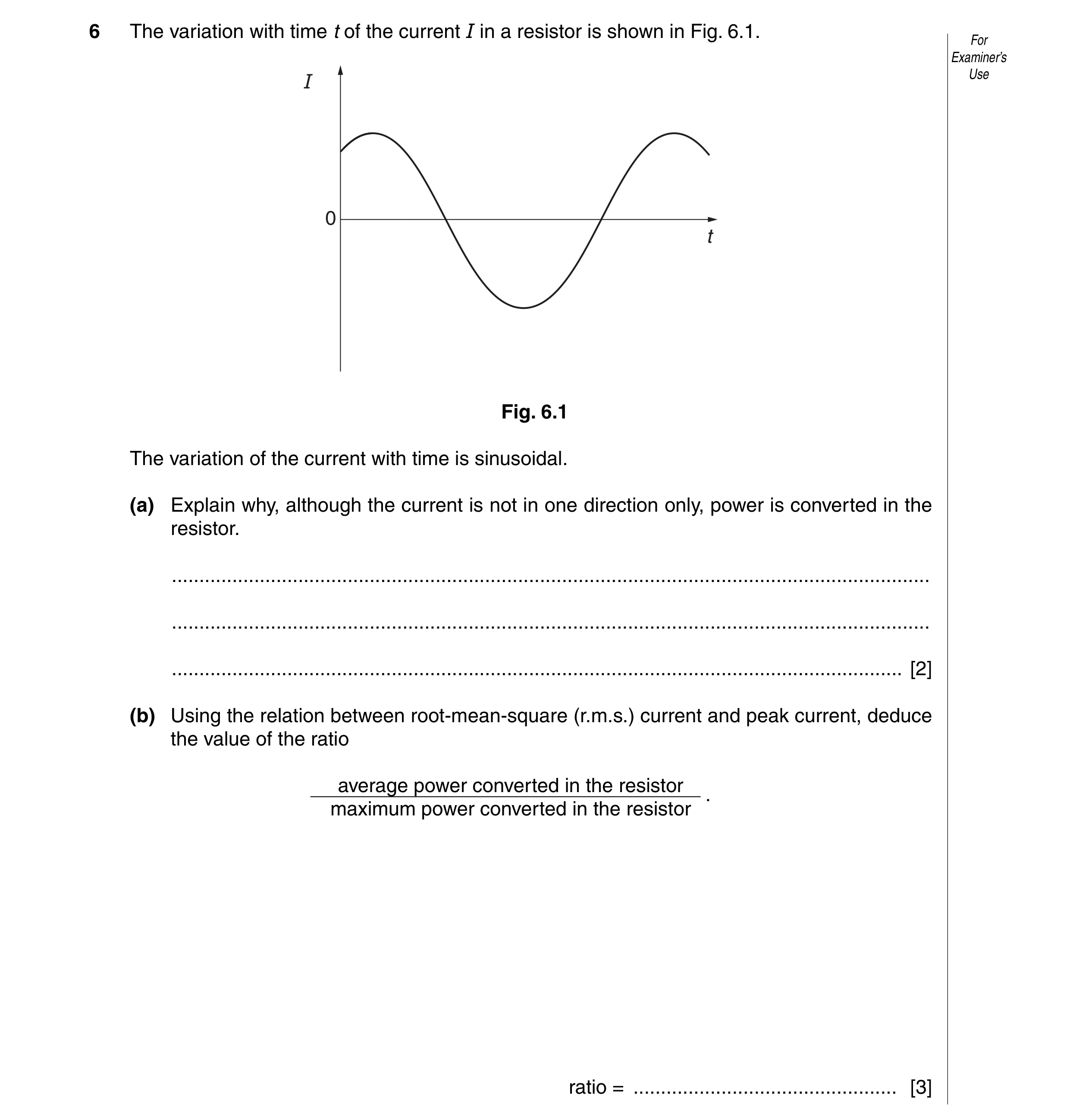
6 The variation with time t of the current I in a resistor is shown in Fig. 6.1. For Examiner’s I Use 0 t Fig. 6.1 The variation of the current with time is sinusoidal. (a) Explain why, although the current is not in one direction only, power is converted in the resistor. … … … [2] (b) Using the relation between root-mean-square (r.m.s.) current and peak current, deduce the value of the ratio average power converted in the resistore . maximum power converted in the resistor ratio = … [3]
5 marks
Mark scheme: 6 (a) power / heating depends on I2 M1 so independent of current direction A1 [2] (b) either maximum power = I02R or average power = IRMS 2R M1 I0 = √2 × IRMS M1 maximum power = 2 × average power ratio = 0.5 A1 [3]
This question in 9702/43 Oct/Nov 2010
Q7 · Many television receivers are connected to an aerial using a coaxial cable 9702/41 May/June 2011
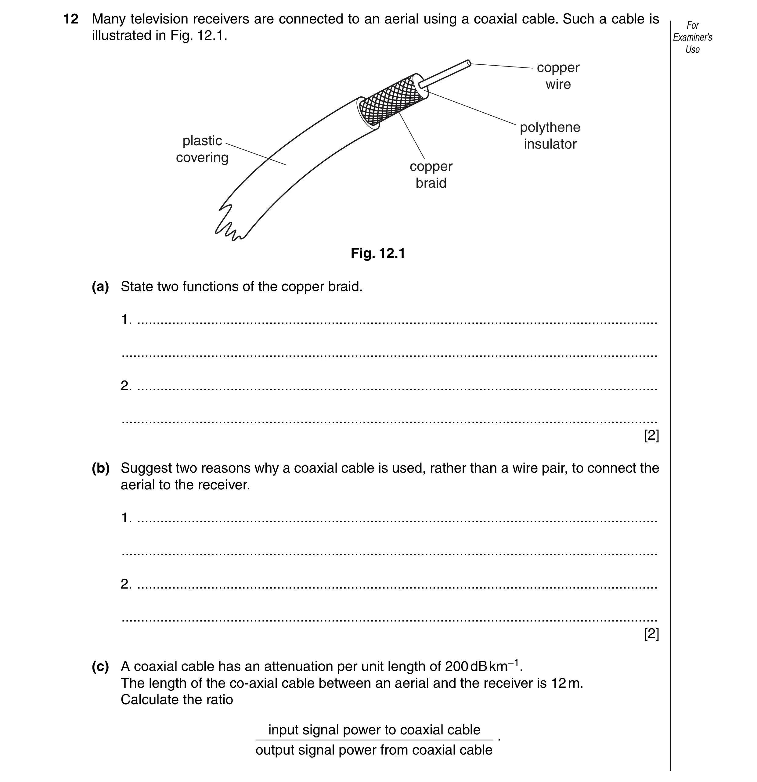
12 Many television receivers are connected to an aerial using a coaxial cable. Such a cable is For illustrated in Fig. 12.1. Examiner’s Use copper wire polythene plastic insulator covering copper braid Fig. 12.1 (a) State two functions of the copper braid. 1. … … 2. … … [2] (b) Suggest two reasons why a coaxial cable is used, rather than a wire pair, to connect the aerial to the receiver. 1. … … 2. … … [2] (c) A coaxial cable has an attenuation per unit length of 200 dB km–1. The length of the co-axial cable between an aerial and the receiver is 12 m. Calculate the ratio input signal power to coaxial cable . output signal power from coaxial cable
4 marks
Mark scheme: 12 (a) e.g. acts as ‘return’ for the signal shields inner core from noise / interference / cross-talk (any two sensible answers, 1 each, max 2) B2 [2] (b) e.g. greater bandwidth less attenuation (per unit length) less noise / interference (any two sensible answers, 1 each, max 2) B2 [2] (c) attenuation is 2.4 dB C1 attenuation = 10 lg(P1 / P2) C1 ratio = 1.7 A1 [3]
This question in 9702/41 May/June 2011
Q8 · Describe the structure of a metal wire strain gauge 9702/42 May/June 2011
9 (a) Describe the structure of a metal wire strain gauge. You may draw a diagram if you wish. … … … … [3] (b) A strain gauge S is connected into the circuit of Fig. 9.1. +4.5 V RF strain gauge S +9 V R – R + –9 V V1 VOUT 1.0 kΩ V2 RF Fig. 9.1 The operational amplifier (op-amp) is ideal. The output potential VOUT of the circuit is given by the expression RF VOUT = × (V2 – V1). R RF (i) State the name given to the ratio R . … [1] (ii) The strain gauge S has resistance 125 Ω when not under strain. For Examiner’s Calculate the magnitude of V1 such that, when the strain gauge S is not strained, the output VOUT is zero. Use V1 = … V [3] (iii) In a particular test, the resistance of S increases to 128 Ω. V1 is unchanged. RF The ratio is 12. R Calculate the magnitude of VOUT . VOUT = … V [2]
9 marks
Mark scheme: 9 (a) thin / fine metal wire B1 lay-out shown as a grid B1 encased in plastic B1 [3] (b) (i) gain (of amplifier) B1 [1] (ii) for VOUT = 0, then V + = V – or V1 = V2 C1 V1 = (1000/1125) × 4.5 C1 V1 = 4.0 V A1 [3] (iii) V2 = (1000 / 1128) × 4.5 = 3.99 V C1 VOUT = 12 × (3.99 – 4.00) = (–) 0.12 V A1 [2]
This question in 9702/42 May/June 2011
Q9 · A sinusoidal alternating voltage supply is connected to a bridge rectifier consisting of… 9702/41 May/June 2012
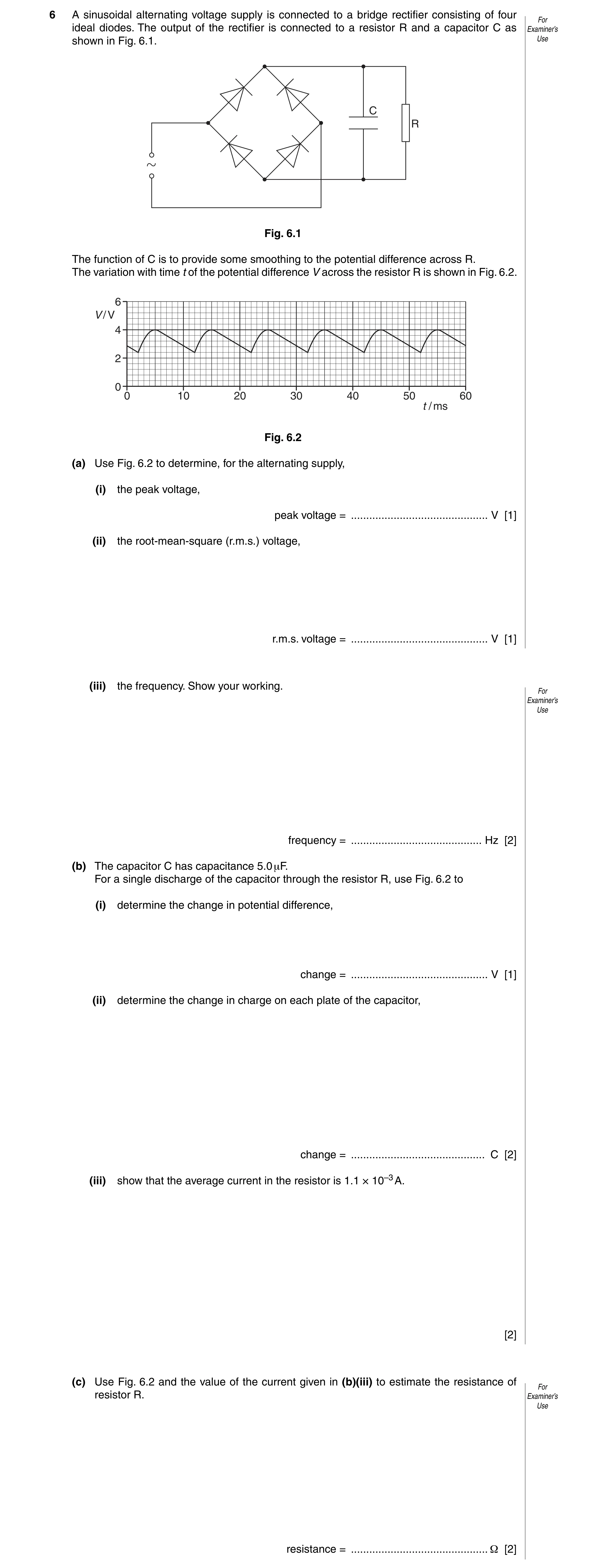
6 A sinusoidal alternating voltage supply is connected to a bridge rectifier consisting of four For ideal diodes. The output of the rectifier is connected to a resistor R and a capacitor C as Examiner’s shown in Fig. 6.1. Use C R Fig. 6.1 The function of C is to provide some smoothing to the potential difference across R. The variation with time t of the potential difference V across the resistor R is shown in Fig. 6.2. 6 V / V 4 2 0 0 10 20 30 40 50 60 t / ms Fig. 6.2 (a) Use Fig. 6.2 to determine, for the alternating supply, (i) the peak voltage, peak voltage = … V [1] (ii) the root-mean-square (r.m.s.) voltage, r.m.s. voltage = … V [1] (iii) the frequency. Show your working. For Examiner’s Use frequency = … Hz [2] (b) The capacitor C has capacitance 5.0 μF. For a single discharge of the capacitor through the resistor R, use Fig. 6.2 to (i) determine the change in potential difference, change = … V [1] (ii) determine the change in charge on each plate of the capacitor, change = … C [2] (iii) show that the average current in the resistor is 1.1 × 10⁻³ A. [2] (c) Use Fig. 6.2 and the value of the current given in (b)(iii) to estimate the resistance of For resistor R. Examiner’s Use resistance = … Ω [2]
11 marks
Mark scheme: 6 (a) (i) peak voltage = 4.0 V A1 [1] (ii) r.m.s. voltage (= 4.0/√2) = 2.8 V A1 [1] (iii) period T = 20 ms M1 frequency = 1 / (20 × 10–3) M1 frequency = 50 Hz A0 [2] (b) (i) change = 4.0 – 2.4 = 1.6 V A1 [1] (ii) ∆Q = C∆V or Q = CV C1 = 5.0 × 10–6 × 1.6 = 8.0 × 10⁻⁶ C A1 [2] (iii) discharge time = 7 ms C1 current = (8.0 × 10⁻⁶) / (7.0 × 10⁻³) M1 = 1.1(4) × 10–3 A A0 [2] (c) average p.d. = 3.2 V C1 resistance = 3.2 / (1.1 × 10⁻³) = 2900 Ω (allow 2800 Ω) A1 [2]
This question in 9702/41 May/June 2012
Q10 · A sinusoidal alternating voltage supply is connected to a bridge rectifier consisting of… 9702/43 May/June 2012
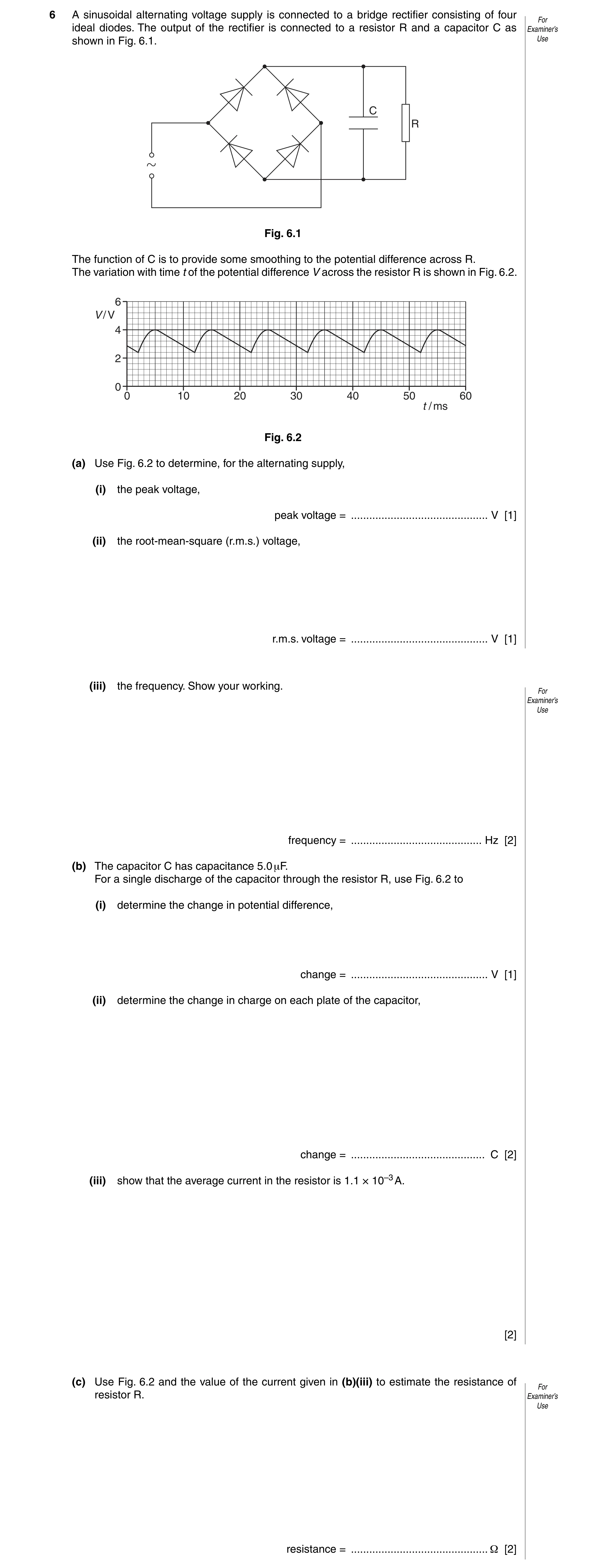
6 A sinusoidal alternating voltage supply is connected to a bridge rectifier consisting of four For ideal diodes. The output of the rectifier is connected to a resistor R and a capacitor C as Examiner’s shown in Fig. 6.1. Use C R Fig. 6.1 The function of C is to provide some smoothing to the potential difference across R. The variation with time t of the potential difference V across the resistor R is shown in Fig. 6.2. 6 V / V 4 2 0 0 10 20 30 40 50 60 t / ms Fig. 6.2 (a) Use Fig. 6.2 to determine, for the alternating supply, (i) the peak voltage, peak voltage = … V [1] (ii) the root-mean-square (r.m.s.) voltage, r.m.s. voltage = … V [1] (iii) the frequency. Show your working. For Examiner’s Use frequency = … Hz [2] (b) The capacitor C has capacitance 5.0 μF. For a single discharge of the capacitor through the resistor R, use Fig. 6.2 to (i) determine the change in potential difference, change = … V [1] (ii) determine the change in charge on each plate of the capacitor, change = … C [2] (iii) show that the average current in the resistor is 1.1 × 10⁻³ A. [2] (c) Use Fig. 6.2 and the value of the current given in (b)(iii) to estimate the resistance of For resistor R. Examiner’s Use resistance = … Ω [2]
11 marks
Mark scheme: 6 (a) (i) peak voltage = 4.0 V A1 [1] (ii) r.m.s. voltage (= 4.0/√2) = 2.8 V A1 [1] (iii) period T = 20 ms M1 frequency = 1 / (20 × 10–3) M1 frequency = 50 Hz A0 [2] (b) (i) change = 4.0 – 2.4 = 1.6 V A1 [1] (ii) ∆Q = C∆V or Q = CV C1 = 5.0 × 10–6 × 1.6 = 8.0 × 10⁻⁶ C A1 [2] (iii) discharge time = 7 ms C1 current = (8.0 × 10⁻⁶) / (7.0 × 10⁻³) M1 = 1.1(4) × 10–3 A A0 [2] (c) average p.d. = 3.2 V C1 resistance = 3.2 / (1.1 × 10⁻³) = 2900 Ω (allow 2800 Ω) A1 [2]
This question in 9702/43 May/June 2012
Q11 · A bridge rectifier consists of four ideal diodes A, B, C and D, connected as shown in Fig 9702/43 Oct/Nov 2012
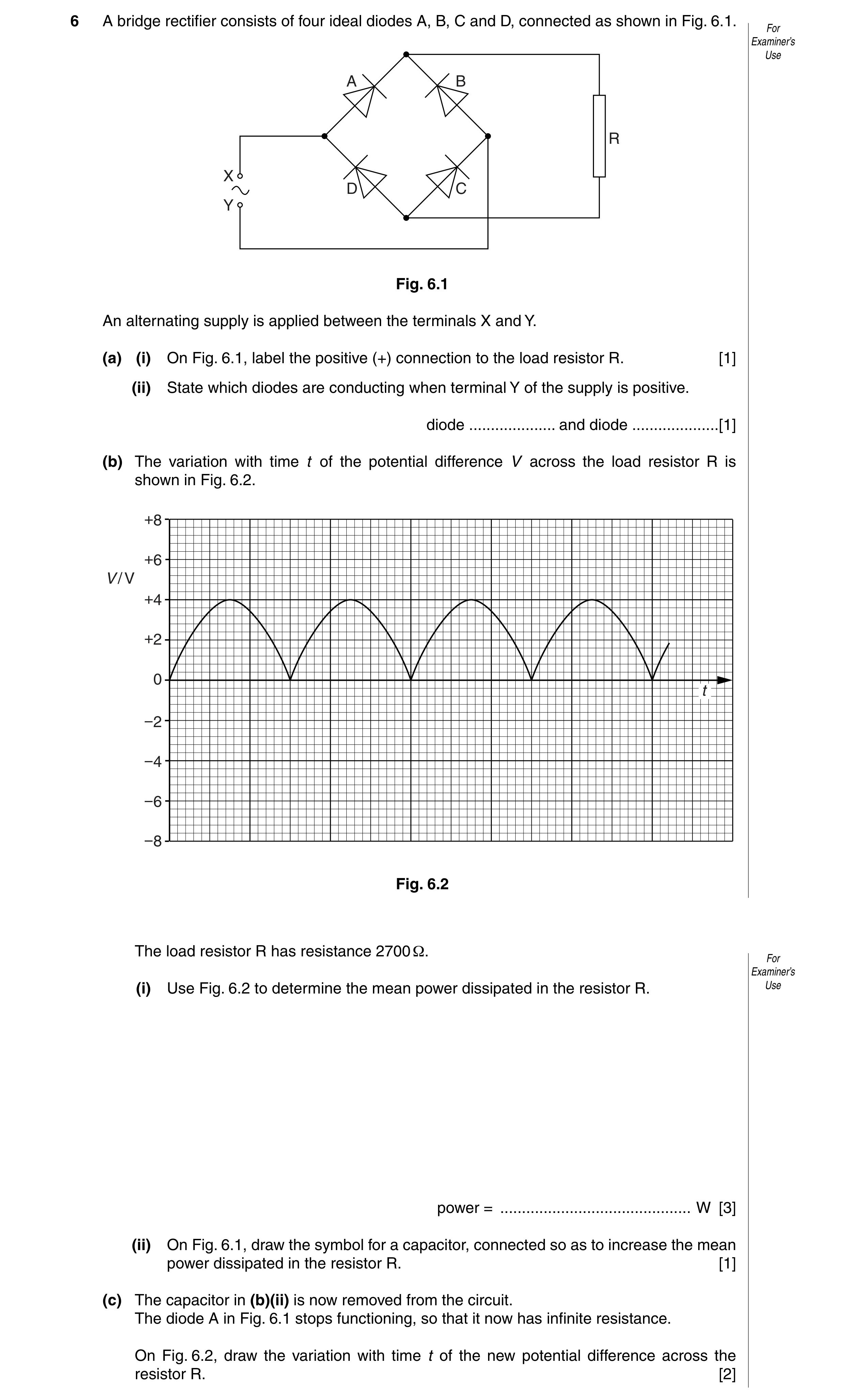
6 A bridge rectifier consists of four ideal diodes A, B, C and D, connected as shown in Fig. 6.1. For Examiner’s Use A B R X D C Y Fig. 6.1 An alternating supply is applied between the terminals X and Y. (a) (i) On Fig. 6.1, label the positive (+) connection to the load resistor R. [1] (ii) State which diodes are conducting when terminal Y of the supply is positive. diode … and diode … [1] (b) The variation with time t of the potential difference V across the load resistor R is shown in Fig. 6.2. +8 +6 V / V +4 +2 0 t −2 −4 −6 −8 Fig. 6.2 The load resistor R has resistance 2700 Ω. For Examiner’s (i) Use Fig. 6.2 to determine the mean power dissipated in the resistor R. Use power = … W [3] (ii) On Fig. 6.1, draw the symbol for a capacitor, connected so as to increase the mean power dissipated in the resistor R. [1] (c) The capacitor in (b)(ii) is now removed from the circuit. The diode A in Fig. 6.1 stops functioning, so that it now has infinite resistance. On Fig. 6.2, draw the variation with time t of the new potential difference across the resistor R. [2]
8 marks
Mark scheme: 6 (a) (i) connection to ‘top’ of resistor labelled as positive B1 [1] (ii) diode B and diode D B1 [1] (b) (i) VP = 4.0 V C1 mean power = VP2/2R C1 = 42 / (2 × 2700) = 2.96 × 10⁻³ W A1 [3] (ii) capacitor, correct symbol, connected in parallel with R B1 [1] (c) graph: half-wave rectification M1 same period and same peak value A1 [2]
This question in 9702/43 Oct/Nov 2012
Q12 · An optic fibre is used for the transmission of digital telephone signals 9702/41 May/June 2013
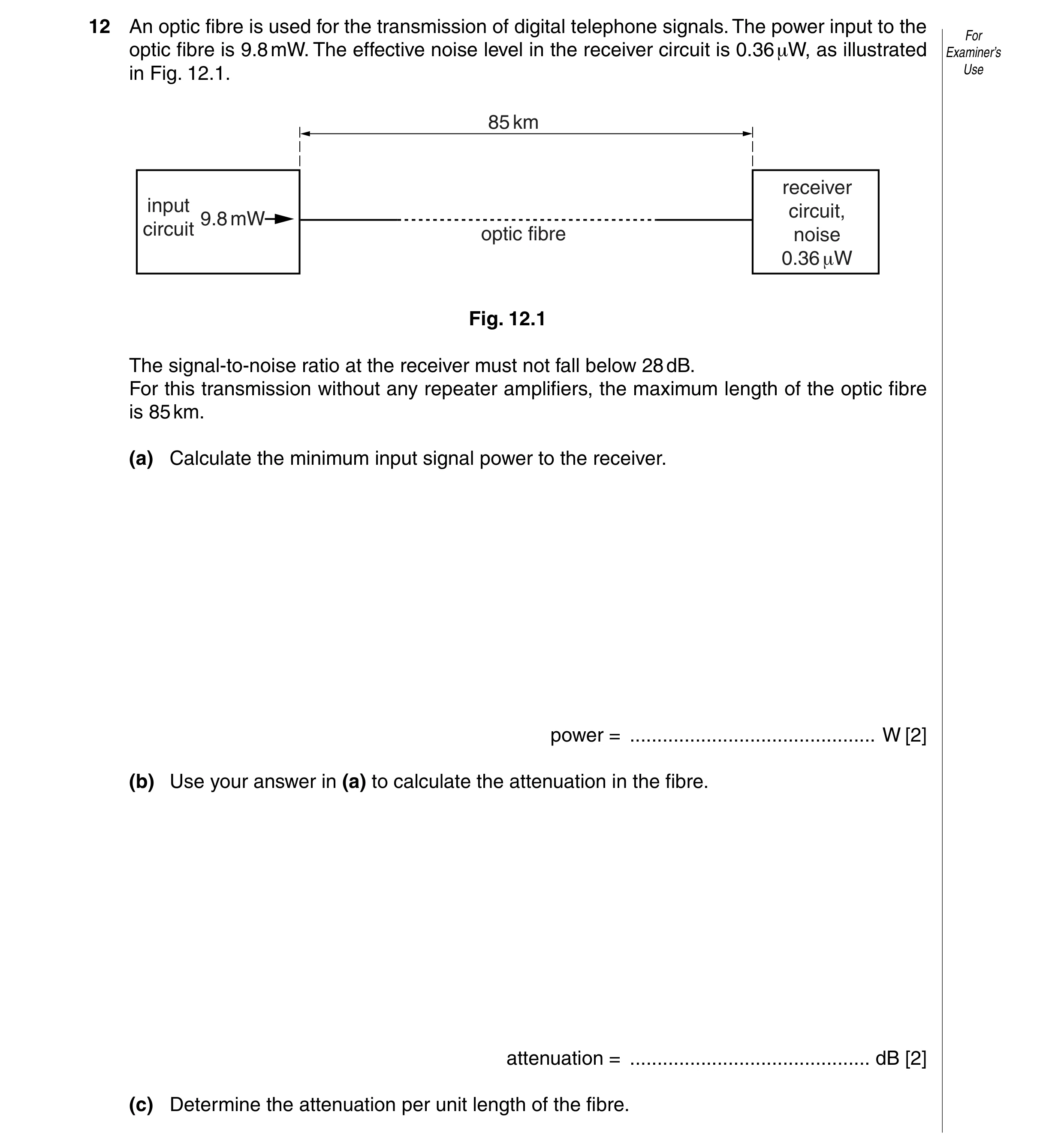
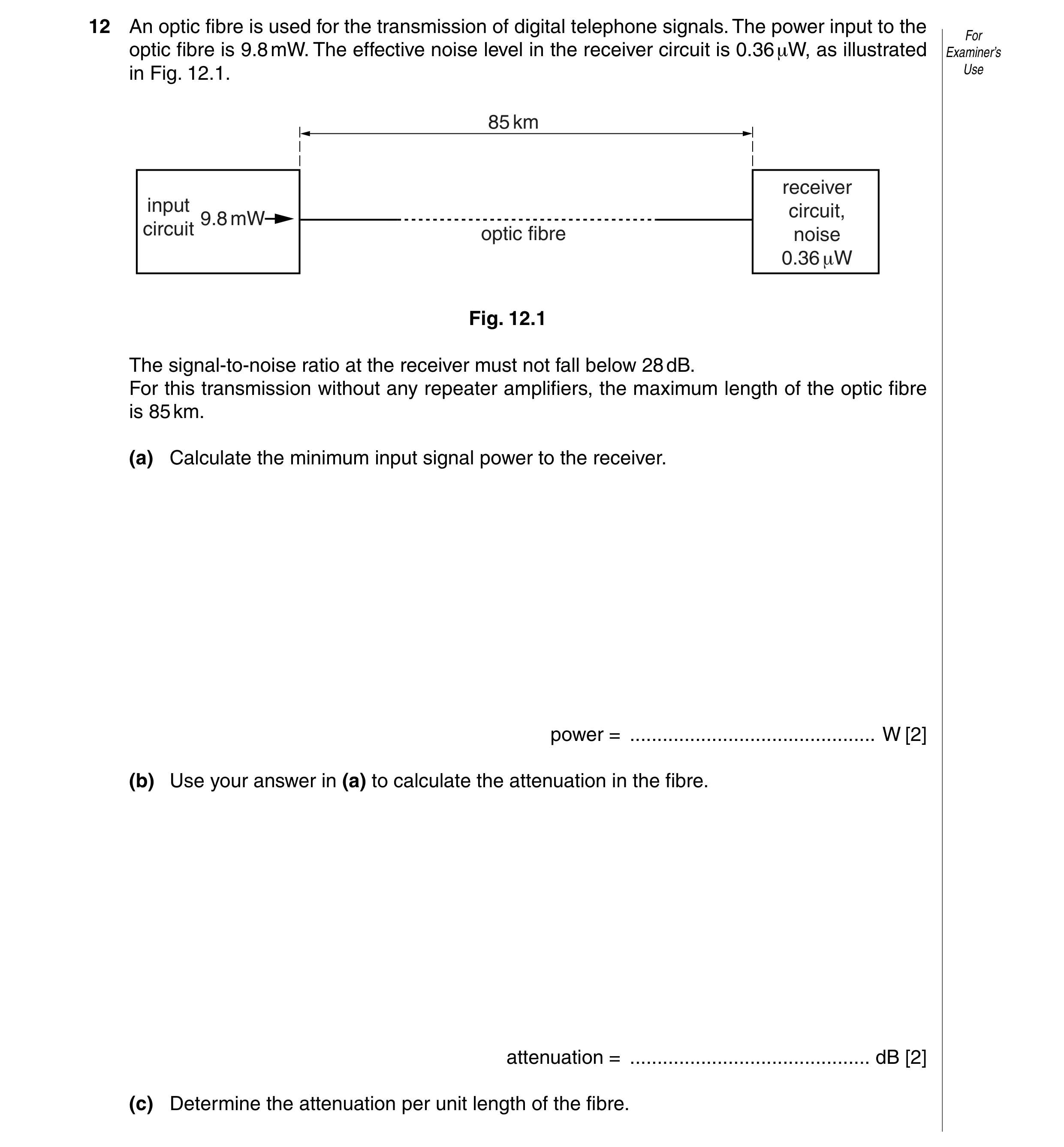
12 An optic fibre is used for the transmission of digital telephone signals. The power input to the For optic fibre is 9.8 mW. The effective noise level in the receiver circuit is 0.36 μW, as illustrated Examiner’s in Fig. 12.1. Use 85 km receiver input circuit, 9.8 mW circuit optic fibre noise 0.36 +W Fig. 12.1 The signal-to-noise ratio at the receiver must not fall below 28 dB. For this transmission without any repeater amplifiers, the maximum length of the optic fibre is 85 km. (a) Calculate the minimum input signal power to the receiver. power = … W [2] (b) Use your answer in (a) to calculate the attenuation in the fibre. attenuation = … dB [2] (c) Determine the attenuation per unit length of the fibre.
4 marks
Mark scheme: 12 (a) for received signal, 28 = 10 lg(P / {0.36 × 10⁻⁶}) C1 P = 2.3 × 10⁻⁴ W A1 [2] (b) loss in fibre = 10 lg({9.8 × 10⁻³} / {2.27 × 10⁻⁴}) C1 = 16 dB A1 [2] (c) attenuation per unit length = 16 / 85 = 0.19 dB km–1 A1 [1]
This question in 9702/41 May/June 2013
Q13 · State Faraday’s law of electromagnetic induction 9702/42 May/June 2013
6 (a) State Faraday’s law of electromagnetic induction. For Examiner’s … Use … … [2] (b) The output of an ideal transformer is connected to a bridge rectifier, as shown in Fig. 6.1. 240 V r.m.s. load resistor Fig. 6.1 The input to the transformer is 240 V r.m.s. and the maximum potential difference across the load resistor is 9.0 V. (i) On Fig. 6.1, mark with the letter P the positive output from the rectifier. [1] (ii) Calculate the ratio number of turns on primary coil . number of turns on secondary coil ratio = … [3] (c) The variation with time t of the potential difference V across the load resistor in (b) is For shown in Fig. 6.2. Examiner’s Use V 0 t Fig. 6.2 A capacitor is now connected in parallel with the load resistor to produce some smoothing. (i) Explain what is meant by smoothing. … … [1] (ii) On Fig. 6.2, draw the variation with time t of the smoothed output potential difference. [2]
9 marks
Mark scheme: 6 (a) (induced) e.m.f. proportional to rate M1 of change of (magnetic) flux (linkage) A1 [2] (b) (i) positive terminal identified (upper connection to load) B1 [1] (ii) VP = √2 × VRMS C1 ratio = 240 √2 / 9 C1 ratio = 38 A1 [3] (VP = VRMS / √2 gives ratio = 18.9 and scores 1/3) (ratio = 240 / 9 = 26.7 scores 1/3) (ratio = 9 / (240 / √2) = 0.0265 is inverted ratio and scores 1/3) (c) (i) e.g. (output) p.d. / voltage / current does not fall to zero e.g. range of (output) p.d. / voltage / current is reduced (any sensible answer) B1 [1] (ii) sketch: same peak value at start of discharge M1 correct shape between one peak and the next A1 [2]
This question in 9702/42 May/June 2013
Q14 · An optic fibre is used for the transmission of digital telephone signals 9702/43 May/June 2013
12 An optic fibre is used for the transmission of digital telephone signals. The power input to the For optic fibre is 9.8 mW. The effective noise level in the receiver circuit is 0.36 μW, as illustrated Examiner’s in Fig. 12.1. Use 85 km receiver input circuit, 9.8 mW circuit optic fibre noise 0.36 +W Fig. 12.1 The signal-to-noise ratio at the receiver must not fall below 28 dB. For this transmission without any repeater amplifiers, the maximum length of the optic fibre is 85 km. (a) Calculate the minimum input signal power to the receiver. power = … W [2] (b) Use your answer in (a) to calculate the attenuation in the fibre. attenuation = … dB [2] (c) Determine the attenuation per unit length of the fibre.
4 marks
Mark scheme: 12 (a) for received signal, 28 = 10 lg(P / {0.36 × 10⁻⁶}) C1 P = 2.3 × 10⁻⁴ W A1 [2] (b) loss in fibre = 10 lg({9.8 × 10⁻³} / {2.27 × 10⁻⁴}) C1 = 16 dB A1 [2] (c) attenuation per unit length = 16 / 85 = 0.19 dB km–1 A1 [1]
This question in 9702/43 May/June 2013
Q15 · State two reasons why frequencies in the gigahertz (GHz) range are used in satellite For… 9702/43 Oct/Nov 2013
12 (a) State two reasons why frequencies in the gigahertz (GHz) range are used in satellite For communication. Examiner’s Use 1. … … 2. … … [2] (b) In one particular satellite communication system, the frequency of the signal transmitted from Earth to the satellite (the up-link) is 6 GHz. The frequency of the signal transmitted back to Earth from the satellite (the down-link) is 4 GHz. Explain why the two signals are transmitted at different frequencies. … … … [2] (c) A signal transmitted from Earth has a power of 3.1 kW. This signal, received by a satellite, has been attenuated by 185 dB. Calculate the power of the signal received by the satellite. power = … W [3]
7 marks
Mark scheme: 12 (a) e.g. no / little ionospheric reflection large information carrying capacity (any two sensible suggestions, 1 each) B2 [2] (b) prevents (very) low power signal received at satellite M1 being swamped by high-power transmitted signal A1 [2] (c) attenuation / dB = 10 lg(P2/P1) C1 185 = 10 lg({3.1 × 10³}/P) C1 P = 9.8 × 10⁻¹⁶ W A1 [3]
This question in 9702/43 Oct/Nov 2013
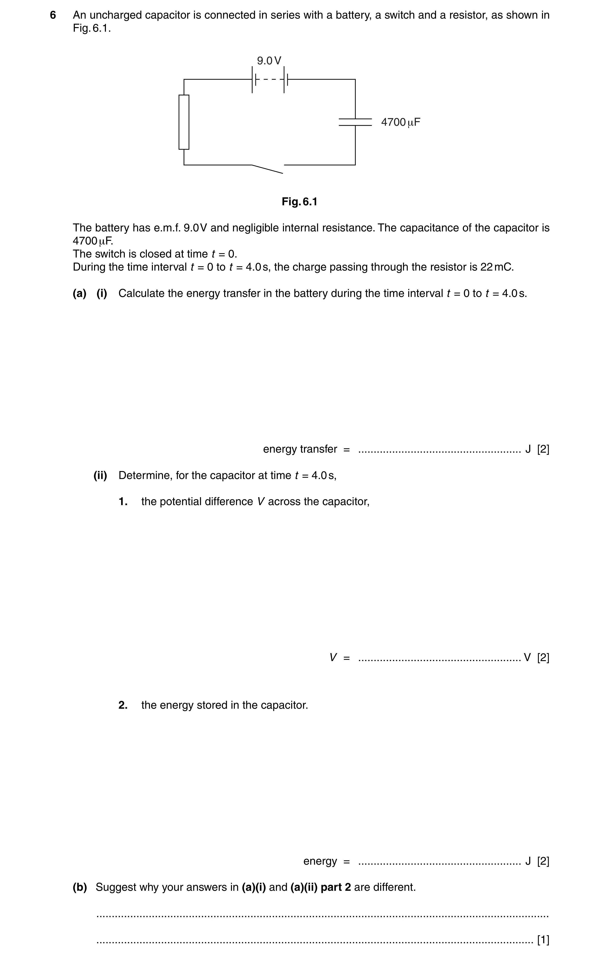
Q16 · An uncharged capacitor is connected in series with a battery, a switch and a resistor, as… 9702/41 May/June 2014
6 An uncharged capacitor is connected in series with a battery, a switch and a resistor, as shown in Fig. 6.1. 9.0 V 4700 +F Fig. 6.1 The battery has e.m.f. 9.0 V and negligible internal resistance. The capacitance of the capacitor is 4700 μF. The switch is closed at time t = 0. During the time interval t = 0 to t = 4.0 s, the charge passing through the resistor is 22 mC. (a) (i) Calculate the energy transfer in the battery during the time interval t = 0 to t = 4.0 s. energy transfer = … J [2] (ii) Determine, for the capacitor at time t = 4.0 s, 1. the potential difference V across the capacitor, V = … V [2] 2. the energy stored in the capacitor. energy = … J [2] (b) Suggest why your answers in (a)(i) and (a)(ii) part 2 are different. … … [1]
7 marks
Mark scheme: 6 (a) (i) energy = EQ C1 = 9.0 × 22 × 10–3 = 0.20 J A1 [2] (ii) 1. C = Q / V V = (22 × 10–3)/(4700 × 10–6) C1 = 4.7 V A1 [2] 2. either E = ½CV 2 C1 = ½ × 4700 × 10–6 × 4.72 = 5.1 × 10⁻² J A1 [2] or E = ½QV (C1) = ½ × 22 × 10–3 × 4.7 = 5.1 × 10⁻² J (A1) or E = ½Q2/C (C1) = ½ × (22 × 10–3)2/4700 ×10–6 = 5.1 × 10⁻² J (A1) GCE AS/A LEVEL – May/June 2014 9702 41 (b) energy lost (as thermal energy) in resistance/wires/battery/resistor B1 [1] (award only if answer in (a)(i) > answer in (a)(ii)2)
This question in 9702/41 May/June 2014
Q17 · An uncharged capacitor is connected in series with a battery, a switch and a resistor, as… 9702/43 May/June 2014
6 An uncharged capacitor is connected in series with a battery, a switch and a resistor, as shown in Fig. 6.1. 9.0 V 4700 +F Fig. 6.1 The battery has e.m.f. 9.0 V and negligible internal resistance. The capacitance of the capacitor is 4700 μF. The switch is closed at time t = 0. During the time interval t = 0 to t = 4.0 s, the charge passing through the resistor is 22 mC. (a) (i) Calculate the energy transfer in the battery during the time interval t = 0 to t = 4.0 s. energy transfer = … J [2] (ii) Determine, for the capacitor at time t = 4.0 s, 1. the potential difference V across the capacitor, V = … V [2] 2. the energy stored in the capacitor. energy = … J [2] (b) Suggest why your answers in (a)(i) and (a)(ii) part 2 are different. … … [1]
7 marks
Mark scheme: 6 (a) (i) energy = EQ C1 = 9.0 × 22 × 10–3 = 0.20 J A1 [2] (ii) 1. C = Q / V V = (22 × 10–3)/(4700 × 10–6) C1 = 4.7 V A1 [2] 2. either E = ½CV 2 C1 = ½ × 4700 × 10–6 × 4.72 = 5.1 × 10⁻² J A1 [2] or E = ½QV (C1) = ½ × 22 × 10–3 × 4.7 = 5.1 × 10⁻² J (A1) or E = ½Q2/C (C1) = ½ × (22 × 10–3)2/4700 ×10–6 = 5.1 × 10⁻² J (A1) GCE AS/A LEVEL – May/June 2014 9702 43 (b) energy lost (as thermal energy) in resistance/wires/battery/resistor B1 [1] (award only if answer in (a)(i) > answer in (a)(ii)2)
This question in 9702/43 May/June 2014
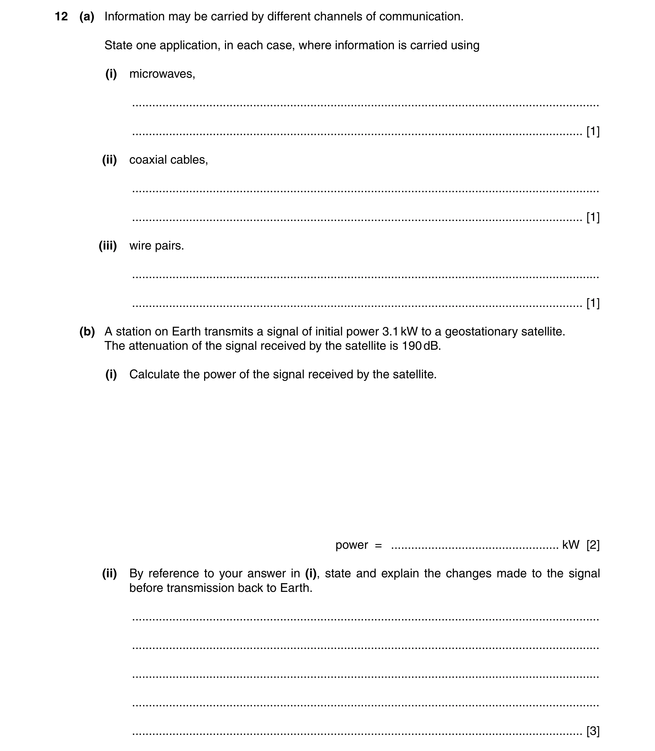
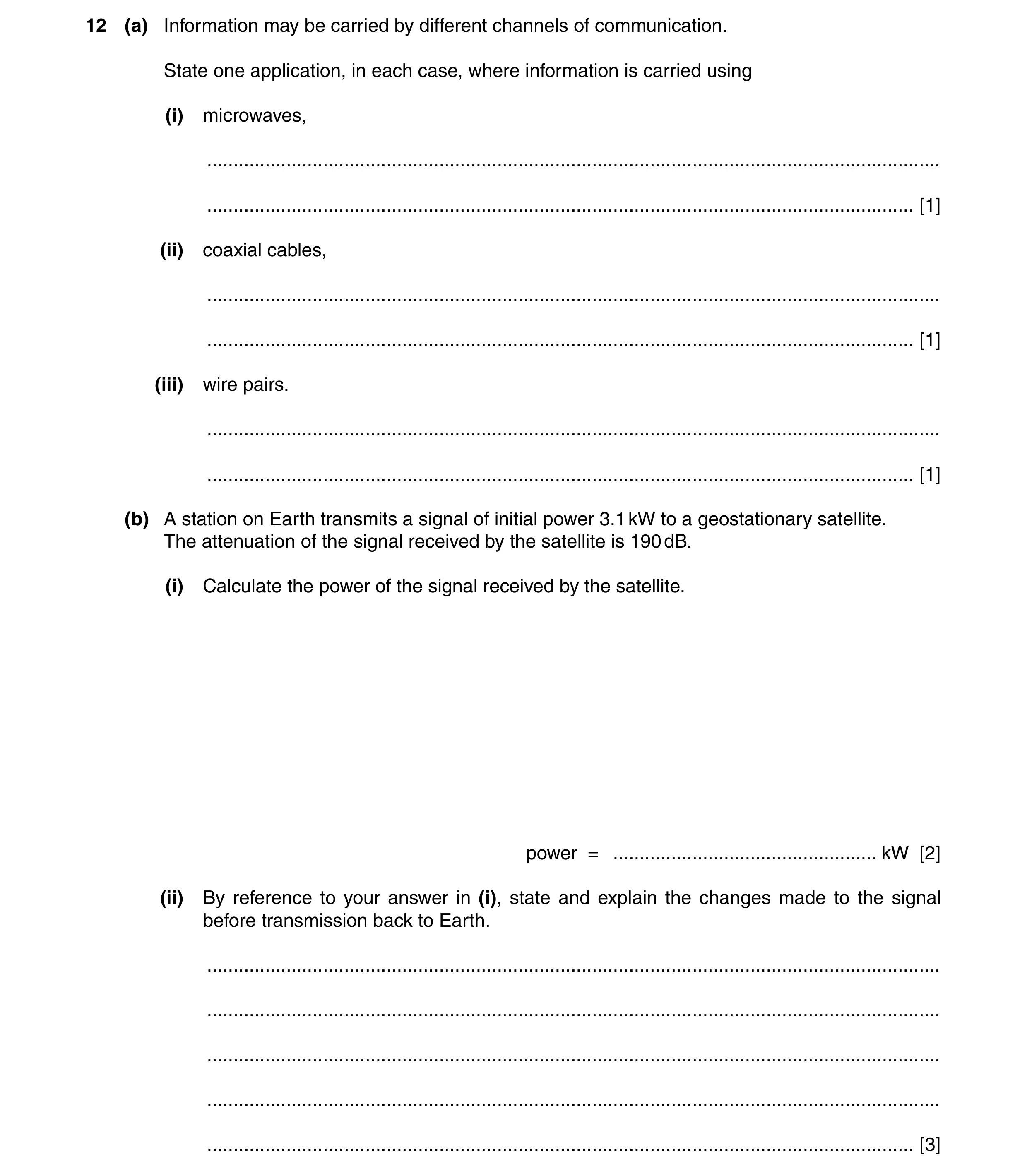
Q18 · Information may be carried by different channels of communication 9702/41 Oct/Nov 2014
12 (a) Information may be carried by different channels of communication. State one application, in each case, where information is carried using (i) microwaves, … … [1] (ii) coaxial cables, … … [1] (iii) wire pairs. … … [1] (b) A station on Earth transmits a signal of initial power 3.1 kW to a geostationary satellite. The attenuation of the signal received by the satellite is 190 dB. (i) Calculate the power of the signal received by the satellite. power = … kW [2] (ii) By reference to your answer in (i), state and explain the changes made to the signal before transmission back to Earth. … … … … … [3]
8 marks
Mark scheme: 12 (a) (i) e.g. satellite communication, mobile phones, line of sight communication, wifi B1 [1] (ii) e.g. connection of TV to aerial, loudspeaker, microphone (if clearly identified) B1 [1] (iii) e.g. a.f. amplifier to loudspeaker, landline for phone B1 [1] (b) (i) attenuation / dB = 10 lg (P2 / P1) C1 –190 = 10 lg (P2 / 3.1) P2 = 3.1 × 10⁻¹⁹ kW A1 [2] (ii) signal is amplified M1 frequency is changed M1 to prevent swamping of up-link signal by down-link (signal) A1 [3]
This question in 9702/41 Oct/Nov 2014
Q19 · Information may be carried by different channels of communication 9702/42 Oct/Nov 2014
12 (a) Information may be carried by different channels of communication. State one application, in each case, where information is carried using (i) microwaves, … … [1] (ii) coaxial cables, … … [1] (iii) wire pairs. … … [1] (b) A station on Earth transmits a signal of initial power 3.1 kW to a geostationary satellite. The attenuation of the signal received by the satellite is 190 dB. (i) Calculate the power of the signal received by the satellite. power = … kW [2] (ii) By reference to your answer in (i), state and explain the changes made to the signal before transmission back to Earth. … … … … … [3]
8 marks
Mark scheme: 12 (a) (i) e.g. satellite communication, mobile phones, line of sight communication, wifi B1 [1] (ii) e.g. connection of TV to aerial, loudspeaker, microphone (if clearly identified) B1 [1] (iii) e.g. a.f. amplifier to loudspeaker, landline for phone B1 [1] (b) (i) attenuation / dB = 10 lg (P2 / P1) C1 –190 = 10 lg (P2 / 3.1) P2 = 3.1 × 10⁻¹⁹ kW A1 [2] (ii) signal is amplified M1 frequency is changed M1 to prevent swamping of up-link signal by down-link (signal) A1 [3]
This question in 9702/42 Oct/Nov 2014
Q20 · On the axes of Fig 9702/43 Oct/Nov 2014
2 (a) On the axes of Fig. 2.1, sketch the variation with distance from a point mass of the gravitational field strength due to the mass. gravitational field strength 0 0 distance Fig. 2.1 [2] (b) On the axes of Fig. 2.2, sketch the variation with speed of the magnitude of the force on a charged particle moving at right-angles to a uniform magnetic field. force 0 0 speed Fig. 2.2 [2] (c) On the axes of Fig. 2.3, sketch the variation with time of the power dissipated in a resistor by a sinusoidal alternating current during two cycles of the current. power 0 0 time Fig. 2.3 [3]
7 marks
Mark scheme: 2 (a) smooth curve with decreasing gradient, not starting at x = 0 M1 end of line not at g = 0 or horizontal A1 [2] (b) straight line with positive gradient M1 line starts at origin A1 [2] (c) sinusoidal shape B1 only positive values and peak / trough height constant B1 4 ‘loops’ B1 [3] 5 4
This question in 9702/43 Oct/Nov 2014
Q21 · In many distribution systems for electrical energy, the energy is transmitted using… 9702/41 May/June 2015
7 In many distribution systems for electrical energy, the energy is transmitted using alternating current at high voltages. Suggest and explain an advantage, one in each case, for the use of (a) alternating voltages, … … … … [2] (b) high voltages. … … … … [2]
4 marks
Mark scheme: 7 (a) can change (output) voltage efficiently or to suit different consumers/appliances B1 by using transformers B1 [2] (b) for same power, current is smaller B1 less heating in cables/wires or thinner cables possible or less voltage loss in cables B1 [2]
This question in 9702/41 May/June 2015
Q22 · One channel of communication is by the use of a coaxial cable 9702/42 May/June 2015
11 One channel of communication is by the use of a coaxial cable. Such a cable is illustrated in Fig. 11.1. protective covering inner copper wire plastic insulation A Fig. 11.1 (a) (i) Suggest the material from which the component labelled A on Fig. 11.1 is made. … [1] (ii) Suggest two functions of the component labelled A. 1. … … 2. … … [2] (b) When a signal travels along the coaxial cable, it is attenuated. (i) State the meaning of attenuation. … … [1] (ii) State and explain why attenuation is frequently measured in decibels (dB). … … … [2] (c) A television aerial is connected to a receiver using a coaxial cable of length 11 m. The attenuation per unit length of the cable is 190 dB km–1. Calculate the ratio output signal from coaxial cable . input signal to coaxial cable ratio = … [3] Please turn over for Question 12.
9 marks
Mark scheme: 11 (a) (i) metal (allow specific example of a metal) B1 [1] (ii) e.g. provides ‘return’ for the signal shields inner core from interference/reduces cross-talk/reduces noise increased security (any two sensible suggestions, 1 each) B2 [2] (b) (i) (gradual) loss of power/intensity/amplitude B1 [1] (ii) dB is a log scale B1 either large (range of) numbers are easier to handle (on a log scale) or compounding attenuations/amplifications is easier B1 [2] (c) attenuation = 190 × 11 × 10–3 = 2.09 dB C1 –2.09 = 10 lg(POUT / PIN) C1 ratio = 0.62 A1 [3]
This question in 9702/42 May/June 2015
Q23 · In many distribution systems for electrical energy, the energy is transmitted using… 9702/43 May/June 2015
7 In many distribution systems for electrical energy, the energy is transmitted using alternating current at high voltages. Suggest and explain an advantage, one in each case, for the use of (a) alternating voltages, … … … … [2] (b) high voltages. … … … … [2]
4 marks
Mark scheme: 7 (a) can change (output) voltage efficiently or to suit different consumers/appliances B1 by using transformers B1 [2] (b) for same power, current is smaller B1 less heating in cables/wires or thinner cables possible or less voltage loss in cables B1 [2]
This question in 9702/43 May/June 2015
Q24 · A battery of e.m.f 9702/41 Oct/Nov 2015
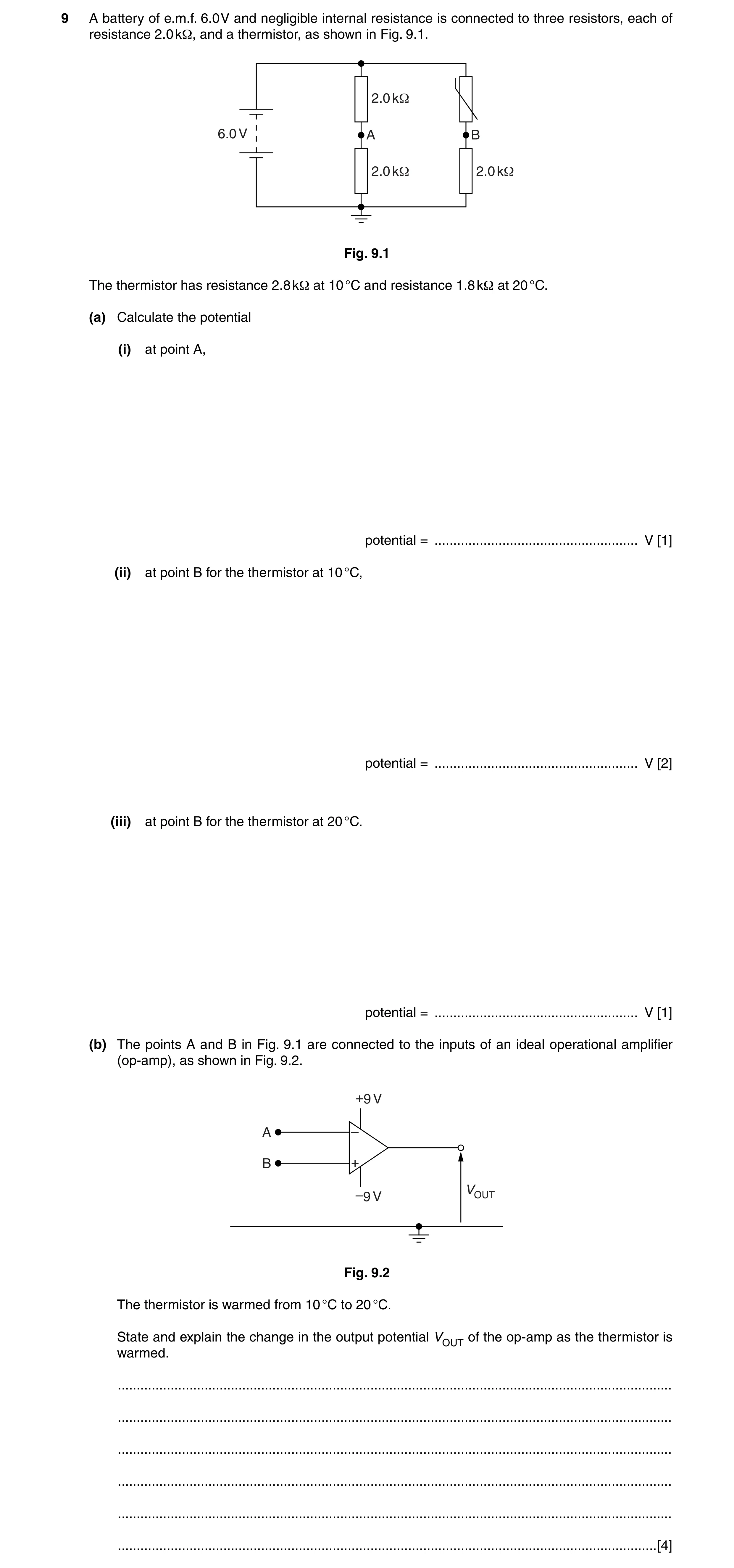
9 A battery of e.m.f. 6.0 V and negligible internal resistance is connected to three resistors, each of resistance 2.0 kΩ, and a thermistor, as shown in Fig. 9.1. 2.0 k1 6.0 V A B 2.0 k1 2.0 k1 Fig. 9.1 The thermistor has resistance 2.8 kΩ at 10 °C and resistance 1.8 kΩ at 20 °C. (a) Calculate the potential (i) at point A, potential = … V [1] (ii) at point B for the thermistor at 10 °C, potential = … V [2] (iii) at point B for the thermistor at 20 °C. potential = … V [1] (b) The points A and B in Fig. 9.1 are connected to the inputs of an ideal operational amplifier (op-amp), as shown in Fig. 9.2. +9 V A – B + VOUT –9 V Fig. 9.2 The thermistor is warmed from 10 °C to 20 °C. State and explain the change in the output potential VOUT of the op-amp as the thermistor is warmed. … … … … … … [4]
8 marks
Mark scheme: 9 (a) (i) (+) 3.0 V B1 [1] (ii) potential = 6.0 × {2.0 / (2.0 + 2.8)} C1 = 2.5 V A1 [2] (iii) potential = 6.0 × {2.0 / (2.0 + 1.8)} = 3.2 V A1 [1] (b) at 10 °C, VA > VB M1 VOUT is –9.0 V (allow “negative saturation”) A1 at 20 °C, VOUT is +9.0 V B1 (if 20 °C considered initially, mark as M1,A1,B1) sudden switch (from –9 V to +9 V) when VA = VB B1 [4]
This question in 9702/41 Oct/Nov 2015
Q25 · A battery of e.m.f 9702/42 Oct/Nov 2015
9 A battery of e.m.f. 6.0 V and negligible internal resistance is connected to three resistors, each of resistance 2.0 kΩ, and a thermistor, as shown in Fig. 9.1. 2.0 k1 6.0 V A B 2.0 k1 2.0 k1 Fig. 9.1 The thermistor has resistance 2.8 kΩ at 10 °C and resistance 1.8 kΩ at 20 °C. (a) Calculate the potential (i) at point A, potential = … V [1] (ii) at point B for the thermistor at 10 °C, potential = … V [2] (iii) at point B for the thermistor at 20 °C. potential = … V [1] (b) The points A and B in Fig. 9.1 are connected to the inputs of an ideal operational amplifier (op-amp), as shown in Fig. 9.2. +9 V A – B + VOUT –9 V Fig. 9.2 The thermistor is warmed from 10 °C to 20 °C. State and explain the change in the output potential VOUT of the op-amp as the thermistor is warmed. … … … … … … [4]
8 marks
Mark scheme: 9 (a) (i) (+) 3.0 V B1 [1] (ii) potential = 6.0 × {2.0 / (2.0 + 2.8)} C1 = 2.5 V A1 [2] (iii) potential = 6.0 × {2.0 / (2.0 + 1.8)} = 3.2 V A1 [1] (b) at 10 °C, VA > VB M1 VOUT is –9.0 V (allow “negative saturation”) A1 at 20 °C, VOUT is +9.0 V B1 (if 20 °C considered initially, mark as M1,A1,B1) sudden switch (from –9 V to +9 V) when VA = VB B1 [4]
This question in 9702/42 Oct/Nov 2015
Q26 · The variation with time t of the sinusoidal current I in a resistor of resistance 450 Ω… 9702/41 May/June 2016
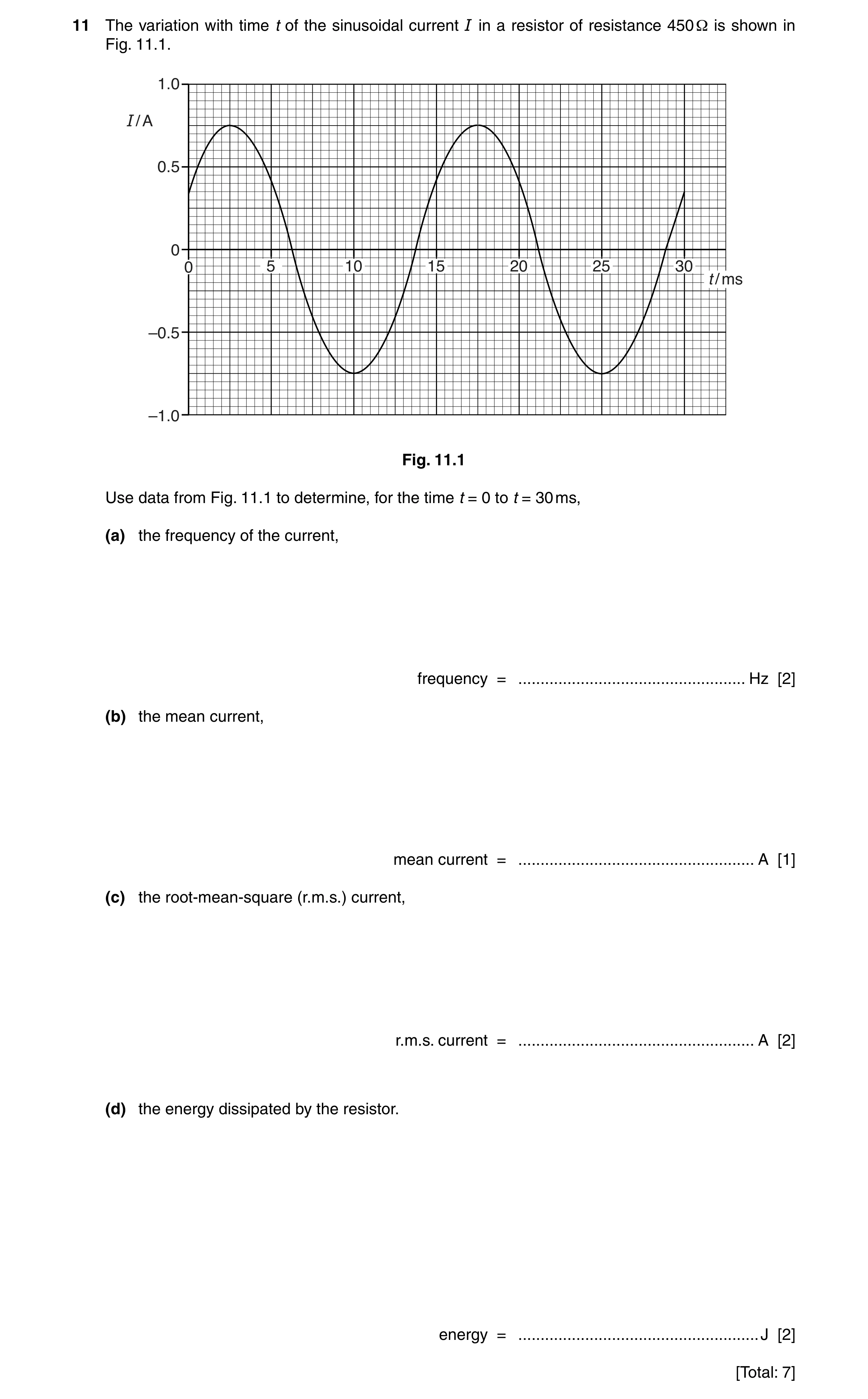
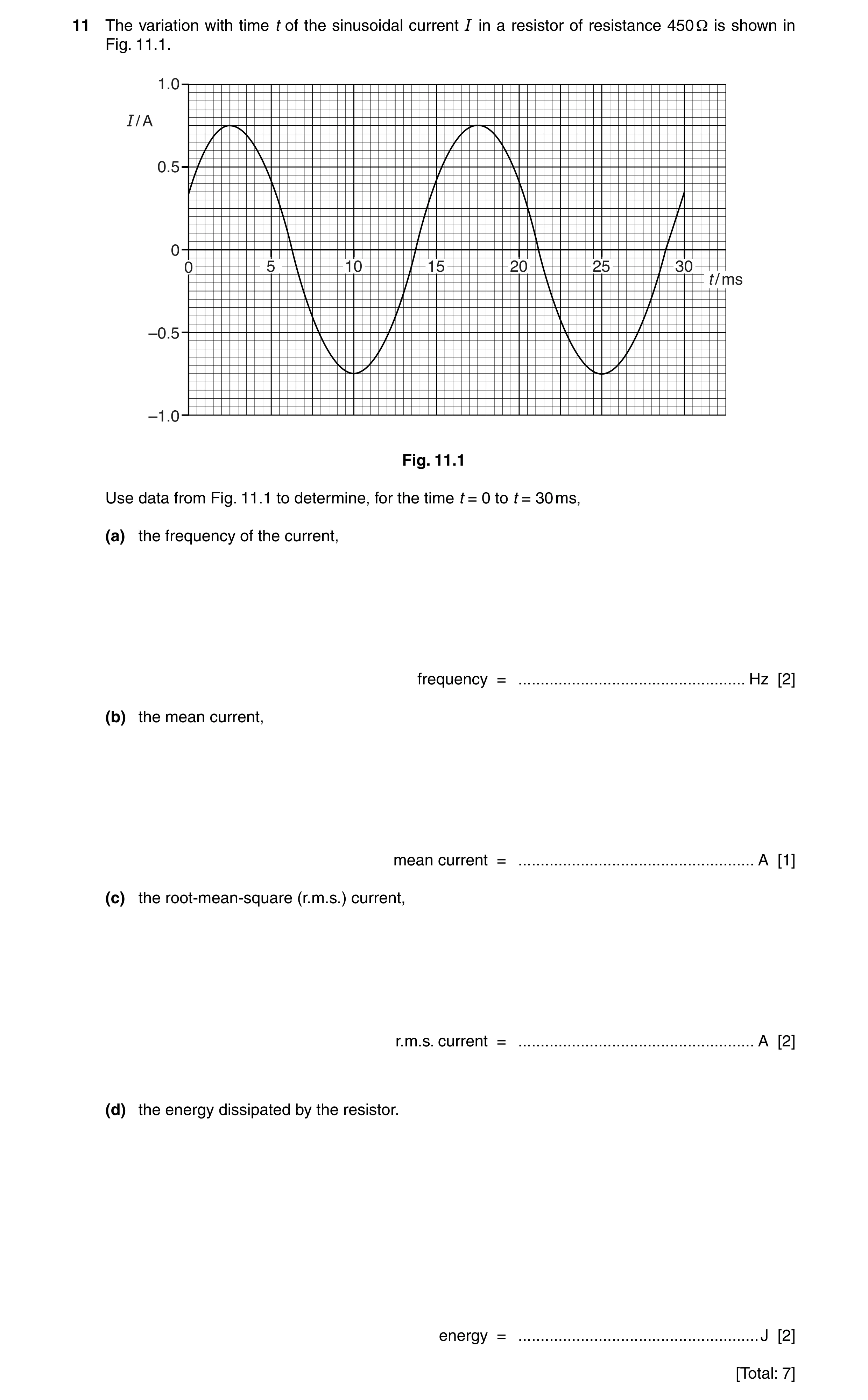
11 The variation with time t of the sinusoidal current I in a resistor of resistance 450 Ω is shown in Fig. 11.1. 1.0 I / A 0.5 0 0 5 10 15 20 25 30 t / ms –0.5 –1.0 Fig. 11.1 Use data from Fig. 11.1 to determine, for the time t = 0 to t = 30 ms, (a) the frequency of the current, frequency = … Hz [2] (b) the mean current, mean current = … A [1] (c) the root-mean-square (r.m.s.) current, r.m.s. current = … A [2] (d) the energy dissipated by the resistor. energy = … J [2] [Total: 7]
7 marks
Mark scheme: 11 (a) period = 15 ms C1 frequency (= 1 / T) = 67 Hz A1 [2] (b) zero A1 [1] (c) Ir.m.s. = I0 / √2 C1 = 0.53 A A1 [2] (d) energy = Ir.m.s. 2 × R × t or ½ I02 × R × t or power = Ir.m.s. 2 × R and energy = power × t C1 energy = 0.532 × 450 × 30 × 10–3 = 3.8 J A1 [2]
This question in 9702/41 May/June 2016
Q27 · An ideal operational amplifier (op-amp) has infinite voltage gain and infinite slew rate 9702/42 May/June 2016
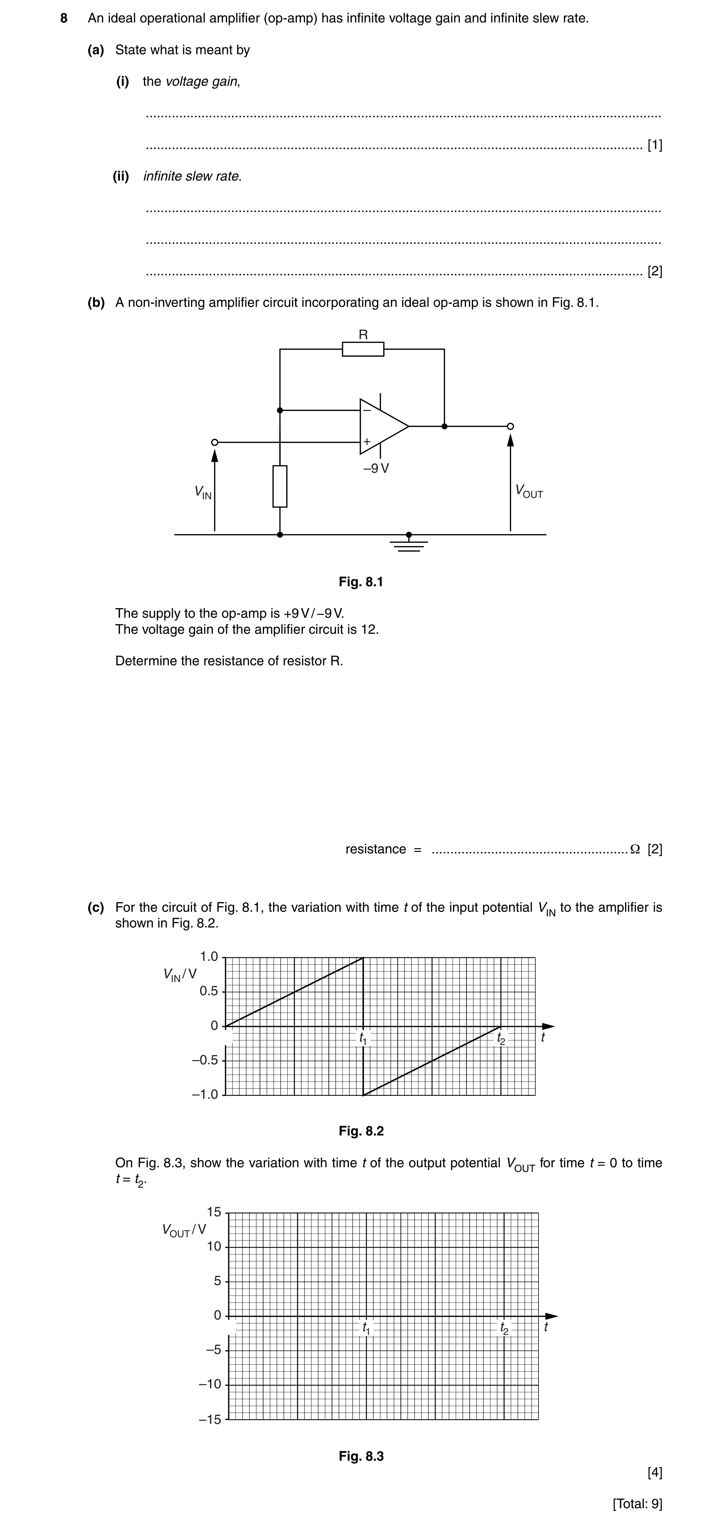
8 An ideal operational amplifier (op-amp) has infinite voltage gain and infinite slew rate. (a) State what is meant by (i) the voltage gain, … … [1] (ii) infinite slew rate. … … … [2] (b) A non-inverting amplifier circuit incorporating an ideal op-amp is shown in Fig. 8.1. 5 – + ² 9 9,1 9287 Fig. 8.1 The supply to the op-amp is +9 V / −9 V. The voltage gain of the amplifier circuit is 12. Determine the resistance of resistor R. resistance = … Ω [2] (c) For the circuit of Fig. 8.1, the variation with time t of the input potential VIN to the amplifier is shown in Fig. 8.2. 1.0 9IN / V 0.5 0 W W W –0.5 –1.0 Fig. 8.2 On Fig. 8.3, show the variation with time t of the output potential VOUT for time t = 0 to time t = t2. 15 9OUT / V 10 5 0 W W W –5 –10 –15 Fig. 8.3 [4] [Total: 9]
9 marks
Mark scheme: 8 (a) (i) gain = voltage output / voltage input B1 [1] (ii) changes in VOUT M1 occur immediately when VIN changes A1 or changes in VIN (M1) result in immediate changes to VOUT (A1) [2] (b) 12 = 1 + R / (1.5 × 10³) C1 R = 16.5 kΩ A1 [2] (c) straight line from (0,0) to (0.75t1, 9.0 V) B1 horizontal line from endpoint of straight line to t1 B1 +9 V to –9 V (or v.v.) at t1 B1 correct line to t2 B1 [4]
This question in 9702/42 May/June 2016
Q28 · The variation with time t of the sinusoidal current I in a resistor of resistance 450 Ω… 9702/43 May/June 2016
11 The variation with time t of the sinusoidal current I in a resistor of resistance 450 Ω is shown in Fig. 11.1. 1.0 I / A 0.5 0 0 5 10 15 20 25 30 t / ms –0.5 –1.0 Fig. 11.1 Use data from Fig. 11.1 to determine, for the time t = 0 to t = 30 ms, (a) the frequency of the current, frequency = … Hz [2] (b) the mean current, mean current = … A [1] (c) the root-mean-square (r.m.s.) current, r.m.s. current = … A [2] (d) the energy dissipated by the resistor. energy = … J [2] [Total: 7]
7 marks
Mark scheme: 11 (a) period = 15 ms C1 frequency (= 1 / T) = 67 Hz A1 [2] (b) zero A1 [1] (c) Ir.m.s. = I0 / √2 C1 = 0.53 A A1 [2] (d) energy = Ir.m.s. 2 × R × t or ½ I02 × R × t or power = Ir.m.s. 2 × R and energy = power × t C1 energy = 0.532 × 450 × 30 × 10–3 = 3.8 J A1 [2]
This question in 9702/43 May/June 2016
Q29 · A coaxial cable is frequently used to connect an aerial to a television receiver 9702/43 Oct/Nov 2017
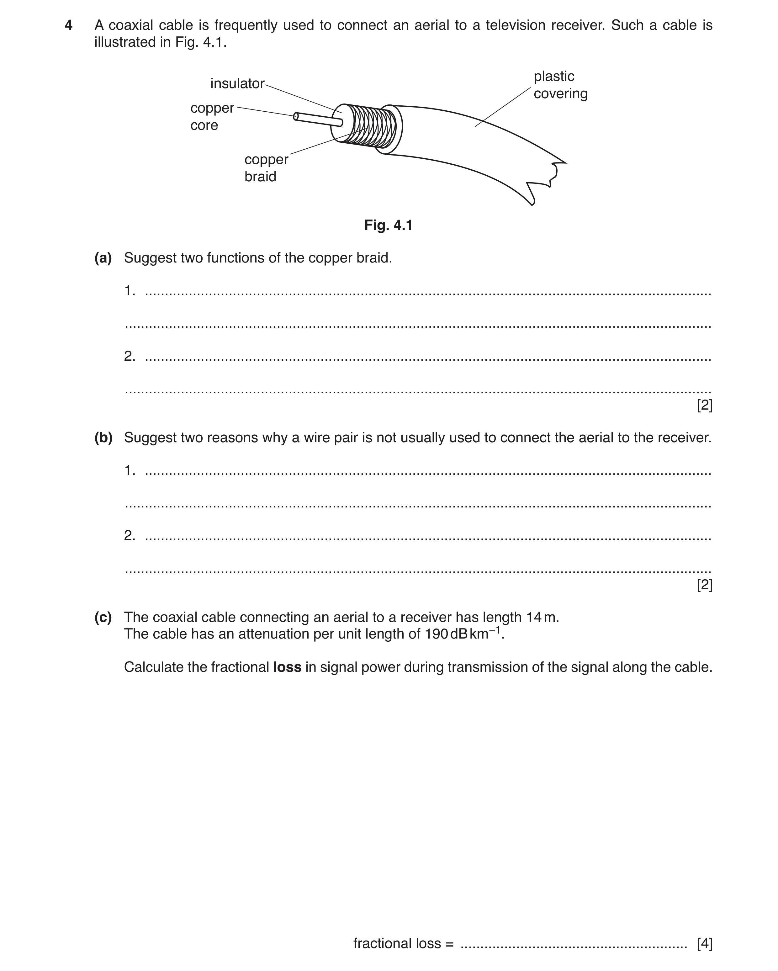
4 A coaxial cable is frequently used to connect an aerial to a television receiver. Such a cable is illustrated in Fig. 4.1. plastic insulator covering copper core copper braid Fig. 4.1 (a) Suggest two functions of the copper braid. 1. … … 2. … … [2] (b) Suggest two reasons why a wire pair is not usually used to connect the aerial to the receiver. 1. … … 2. … … [2] (c) The coaxial cable connecting an aerial to a receiver has length 14 m. The cable has an attenuation per unit length of 190 dB km−1. Calculate the fractional loss in signal power during transmission of the signal along the cable. fractional loss = … [4]
8 marks
Mark scheme: 4(a) acts as ‘return’ (conductor) for signal • shielding from noise/crosstalk/interference Two sensible suggestions, 1 mark each. B2 4(b) • small bandwidth • (there is) noise/interference/crosstalk • large attenuation/energy loss • reflections due to poor impedance matching Two sensible suggestions, 1 mark each. B2 4(c) attenuation = 190 × 14 × 10–3 (= 2.66 dB) C1 ratio / dB = (–)10 lg(P2 / P1) C1 2.66 = –10 lg (POUT / PIN) POUT/ PIN = 0.54 C1 fractional loss = 1 – (POUT / PIN) = 1 – 0.54 = 0.46 A1 or 2.66 = 10 lg (PIN / POUT) PIN/ POUT = 1.85 (C1) fractional loss = (PIN – POUT) / PIN = (1.85 – 1) / 1.85 = 0.46 (A1)
This question in 9702/43 Oct/Nov 2017
Q30 · State three features of the orbit of a geostationary satellite 9702/42 Feb/March 2019
4 (a) State three features of the orbit of a geostationary satellite. 1. … … 2. … … 3. … … [3] (b) A signal is transmitted from Earth to a geostationary satellite. Initially, the signal has power 3.2 kW. The signal is attenuated by 194 dB. Calculate the signal power received by the satellite. power = … W [2] (c) Suggest one advantage and one disadvantage of the use of geostationary satellites compared with polar-orbiting satellites for communication between points on the Earth’s surface. advantage: … … disadvantage: … … [2] [Total: 7]
7 marks
Mark scheme: 4(a) Any three from: above the Equator period 24 hours orbits west to east one particular orbital radius B3 4(b) attenuation = 10 lg(P1 / P2) 194 = 10 lg (3.2 × 10³ / P2) C1 P2 = 1.3 × 10⁻¹⁶ W A1 4(c) advantage: e.g. no tracking required B1 disadvantage: e.g. longer time delay B1
This question in 9702/42 Feb/March 2019
Q31 · A section of a coaxial cable is shown in Fig 9702/41 Oct/Nov 2019
5 (a) A section of a coaxial cable is shown in Fig. 5.1. copper braid insulation copper wire plastic covering Fig. 5.1 (i) Suggest two functions of the copper braid. 1. … … 2. … … [2] (ii) Suggest one application of a coaxial cable for the transmission of electrical signals. … … [1] (b) (i) The constant noise power in a transmission cable is 7.6 μW. The minimum acceptable signal-to-noise ratio is 32 dB. Calculate the minimum acceptable signal power PMIN in the cable. PMIN = … W [2] (ii) The input power of the signal to the transmission cable is 2.6 W. The attenuation per unit length of the cable is 6.3 dB km–1. Use your answer in (i) to determine the maximum uninterrupted length L of cable along which the signal may be transmitted. L = … km [2] [Total: 7]
7 marks
Mark scheme: 5(a)(i) provides return for the signal B1 shields signal from noise B1 5(a)(ii) e.g. connection between aerial and TV set B1 5(b)(i) gain / dB = 10 lg (P1 / P2) C1 32 = 10 lg {PMIN / (7.6 × 10⁻⁶)} PMIN = 0.012 W A1 5(b)(ii) attenuation per unit length = (1 / L) × 10 lg (P1 / P2) 6.3 = (1 / L) × 10 lg (2.6 / 0.012) C1 L = 3.7 km A1
This question in 9702/41 Oct/Nov 2019
Q32 · A section of a coaxial cable is shown in Fig 9702/43 Oct/Nov 2019
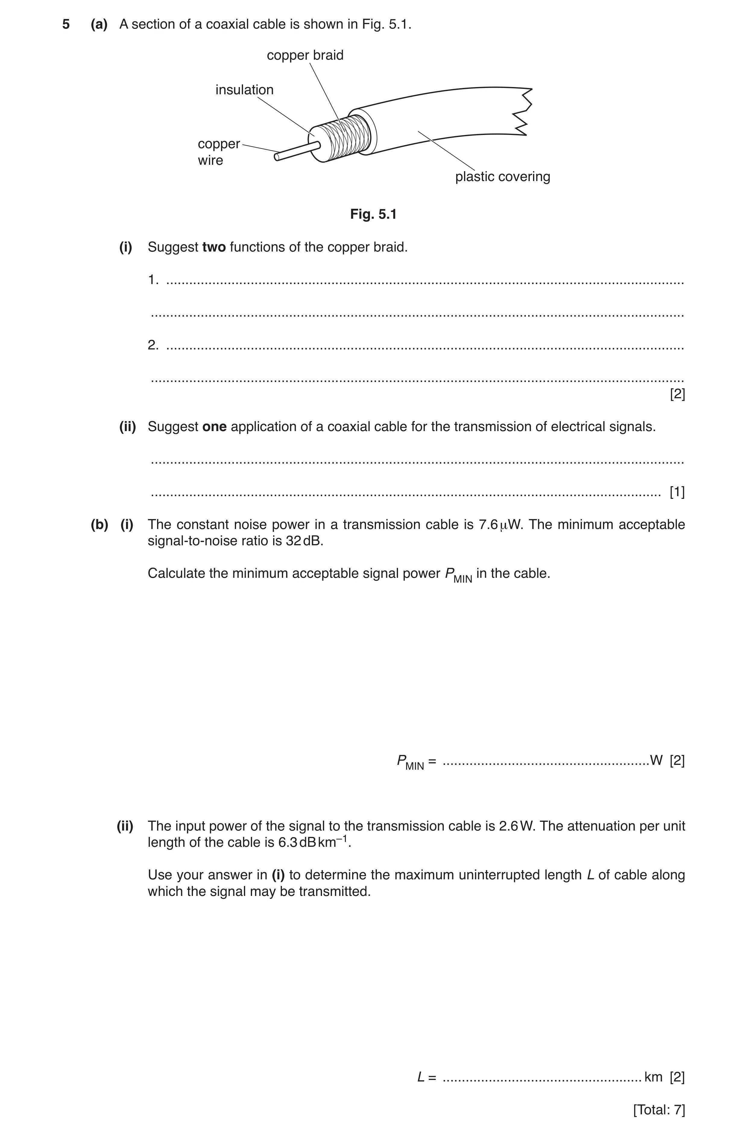
5 (a) A section of a coaxial cable is shown in Fig. 5.1. copper braid insulation copper wire plastic covering Fig. 5.1 (i) Suggest two functions of the copper braid. 1. … … 2. … … [2] (ii) Suggest one application of a coaxial cable for the transmission of electrical signals. … … [1] (b) (i) The constant noise power in a transmission cable is 7.6 μW. The minimum acceptable signal-to-noise ratio is 32 dB. Calculate the minimum acceptable signal power PMIN in the cable. PMIN = … W [2] (ii) The input power of the signal to the transmission cable is 2.6 W. The attenuation per unit length of the cable is 6.3 dB km–1. Use your answer in (i) to determine the maximum uninterrupted length L of cable along which the signal may be transmitted. L = … km [2] [Total: 7]
7 marks
Mark scheme: 5(a)(i) provides return for the signal B1 shields signal from noise B1 5(a)(ii) e.g. connection between aerial and TV set B1 5(b)(i) gain / dB = 10 lg (P1 / P2) C1 32 = 10 lg {PMIN / (7.6 × 10⁻⁶)} PMIN = 0.012 W A1 5(b)(ii) attenuation per unit length = (1 / L) × 10 lg (P1 / P2) 6.3 = (1 / L) × 10 lg (2.6 / 0.012) C1 L = 3.7 km A1
This question in 9702/43 Oct/Nov 2019
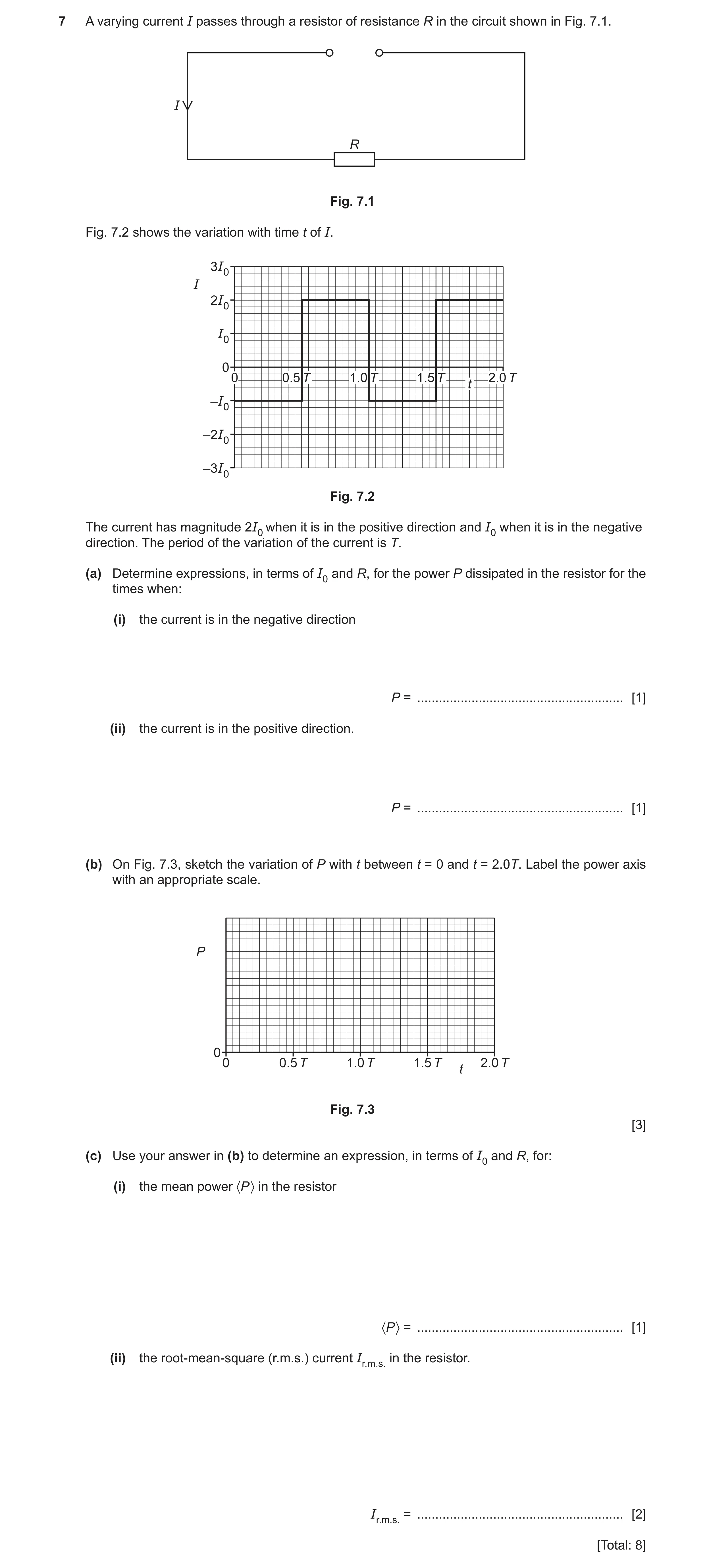
Q33 · A varying current I passes through a resistor of resistance R in the circuit shown in Fig 9702/41 Oct/Nov 2023
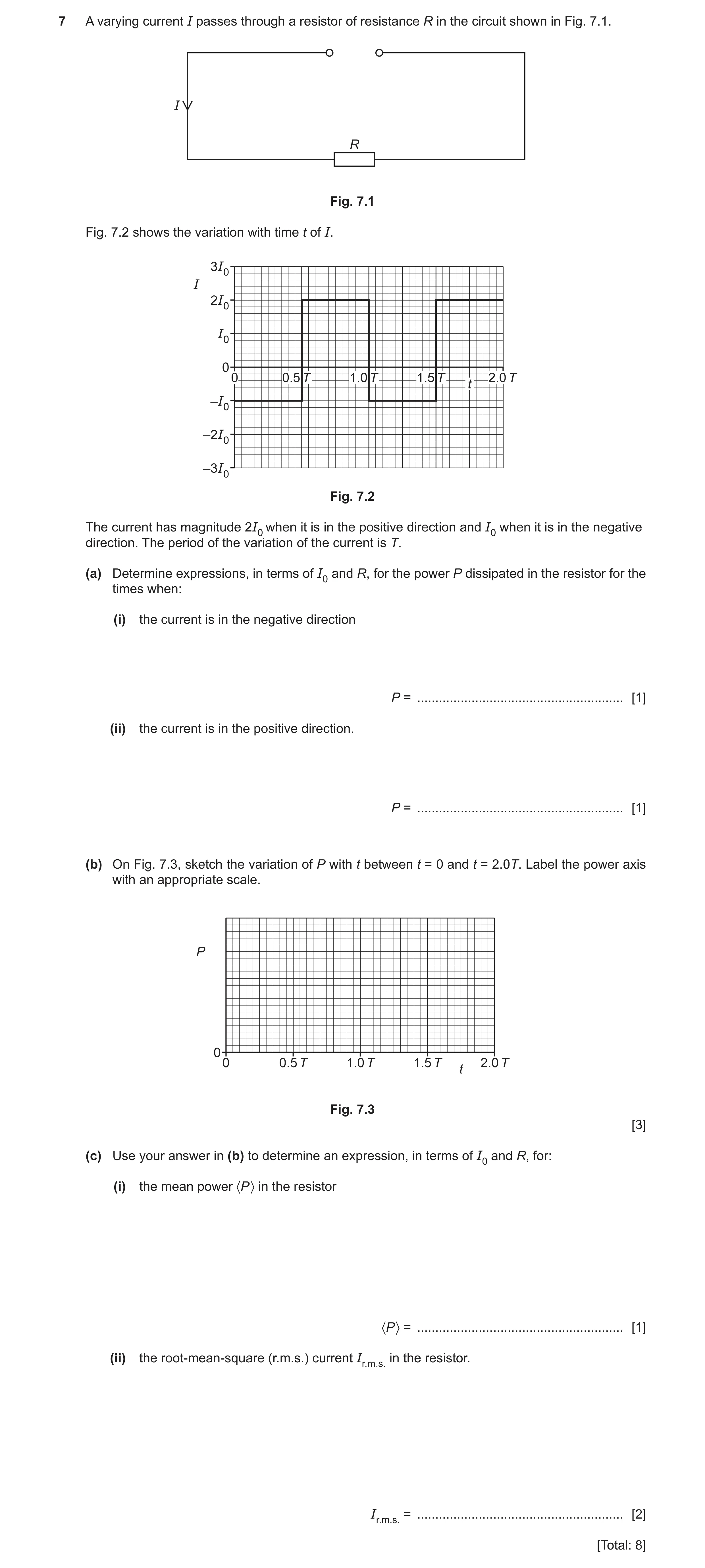
7 A varying current I passes through a resistor of resistance R in the circuit shown in Fig. 7.1. I R Fig. 7.1 Fig. 7.2 shows the variation with time t of I. 3I0 I 2I0 I0 0 0 0.5 T 1.0 T 1.5 T 2.0 T t –I0 –2I0 –3I0 Fig. 7.2 The current has magnitude 2I0 when it is in the positive direction and I0 when it is in the negative direction. The period of the variation of the current is T. (a) Determine expressions, in terms of I0 and R, for the power P dissipated in the resistor for the times when: (i) the current is in the negative direction P = … [1] (ii) the current is in the positive direction. P = … [1] (b) On Fig. 7.3, sketch the variation of P with t between t = 0 and t = 2.0T. Label the power axis with an appropriate scale. P 0 0 0.5 T 1.0 T 1.5 T 2.0 T t Fig. 7.3 [3] (c) Use your answer in (b) to determine an expression, in terms of I0 and R, for: (i) the mean power 〈P 〉 in the resistor 〈P 〉 = … [1] (ii) the root-mean-square (r.m.s.) current Ir.m.s. in the resistor. Ir.m.s. = … [2] [Total: 8]
8 marks
Mark scheme: 7(a)(i) P = I02R A1 7(a)(ii) P = 4I02R A1 7(b) sketch: square wave of period T, with P always non-zero B1 horizontal lines, from 0 to 0.5T and from 1.0T to 1.5T, all at the same level that the scale indicates to be I02R B1 horizontal lines, from 0.5T to 1.0T and from 1.5T to 2.0T, at a level that is four times higher than the lower lines B1 7(c)(i) <P> = (5/2)I02R A1 7(c)(ii) <P> = Ir.m.s.2R C1 Ir.m.s.2R = (5/2)I02R A1 Ir.m.s. = √(5/2) I0
This question in 9702/41 Oct/Nov 2023
Q34 · A varying current I passes through a resistor of resistance R in the circuit shown in Fig 9702/43 Oct/Nov 2023
7 A varying current I passes through a resistor of resistance R in the circuit shown in Fig. 7.1. I R Fig. 7.1 Fig. 7.2 shows the variation with time t of I. 3I0 I 2I0 I0 0 0 0.5 T 1.0 T 1.5 T 2.0 T t –I0 –2I0 –3I0 Fig. 7.2 The current has magnitude 2I0 when it is in the positive direction and I0 when it is in the negative direction. The period of the variation of the current is T. (a) Determine expressions, in terms of I0 and R, for the power P dissipated in the resistor for the times when: (i) the current is in the negative direction P = … [1] (ii) the current is in the positive direction. P = … [1] (b) On Fig. 7.3, sketch the variation of P with t between t = 0 and t = 2.0T. Label the power axis with an appropriate scale. P 0 0 0.5 T 1.0 T 1.5 T 2.0 T t Fig. 7.3 [3] (c) Use your answer in (b) to determine an expression, in terms of I0 and R, for: (i) the mean power 〈P 〉 in the resistor 〈P 〉 = … [1] (ii) the root-mean-square (r.m.s.) current Ir.m.s. in the resistor. Ir.m.s. = … [2] [Total: 8]
8 marks
Mark scheme: 7(a)(i) P = I02R A1 7(a)(ii) P = 4I02R A1 7(b) sketch: square wave of period T, with P always non-zero B1 horizontal lines, from 0 to 0.5T and from 1.0T to 1.5T, all at the same level that the scale indicates to be I02R B1 horizontal lines, from 0.5T to 1.0T and from 1.5T to 2.0T, at a level that is four times higher than the lower lines B1 7(c)(i) <P> = (5/2)I02R A1 7(c)(ii) <P> = Ir.m.s.2R C1 Ir.m.s.2R = (5/2)I02R A1 Ir.m.s. = √(5/2) I0
This question in 9702/43 Oct/Nov 2023
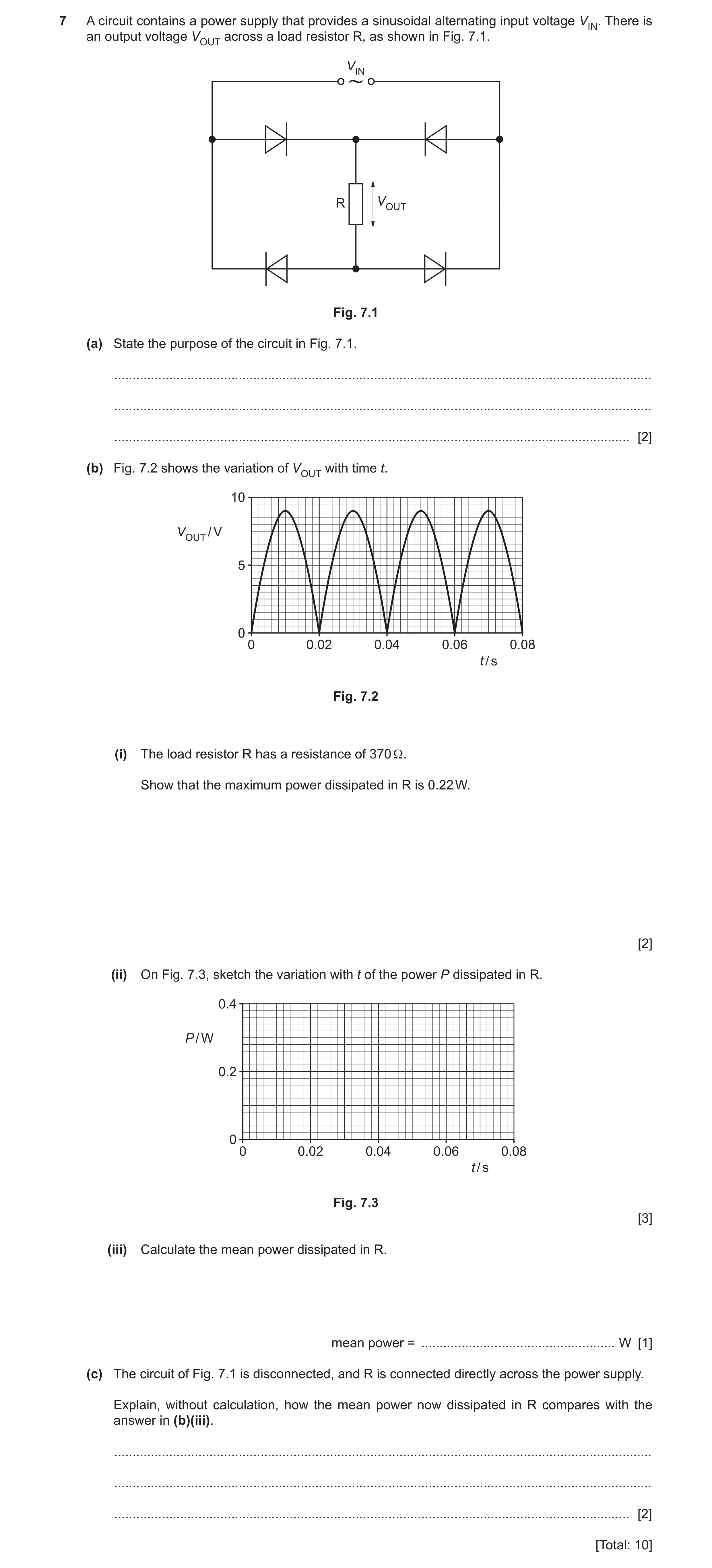
Q35 · A circuit contains a power supply that provides a sinusoidal alternating input voltage VIN 9702/41 May/June 2024
7 A circuit contains a power supply that provides a sinusoidal alternating input voltage VIN. There is an output voltage VOUT across a load resistor R, as shown in Fig. 7.1. VIN R VOUT Fig. 7.1 (a) State the purpose of the circuit in Fig. 7.1. … … … [2] (b) Fig. 7.2 shows the variation of VOUT with time t. 10 VOUT / V 5 0 0 0.02 0.04 0.06 0.08 t / s Fig. 7.2 (i) The load resistor R has a resistance of 370 Ω. Show that the maximum power dissipated in R is 0.22 W. [2] (ii) On Fig. 7.3, sketch the variation with t of the power P dissipated in R. 0.4 P / W 0.2 0 0 0.02 0.04 0.06 0.08 t / s Fig. 7.3 [3] (iii) Calculate the mean power dissipated in R. mean power = … W [1] (c) The circuit of Fig. 7.1 is disconnected, and R is connected directly across the power supply. Explain, without calculation, how the mean power now dissipated in R compares with the answer in (b)(iii). … … … [2] [Total: 10]
10 marks
Mark scheme: 7(a) rectification (of the input voltage) M1 full-wave A1 7(b)(i) P = V2 / R or maximum V = 9.0 V C1 PMAX = 9.02 / 370 = 0.22 W A1 7(b)(ii) sinusoidal shape with minima sitting on the time axis B1 correct frequency and phase, with minima at 0, 0.02, 0.04, 0.06 and 0.08 s and maxima at 0.01, 0.03, 0.05 and 0.07 s B1 all maxima shown at 0.22 W B1 7(b)(iii) mean power = peak power / 2 = 0.22 / 2 = 0.11 W A1 7(c) power–time graph is identical B1 (so) mean powers are equal B1
This question in 9702/41 May/June 2024
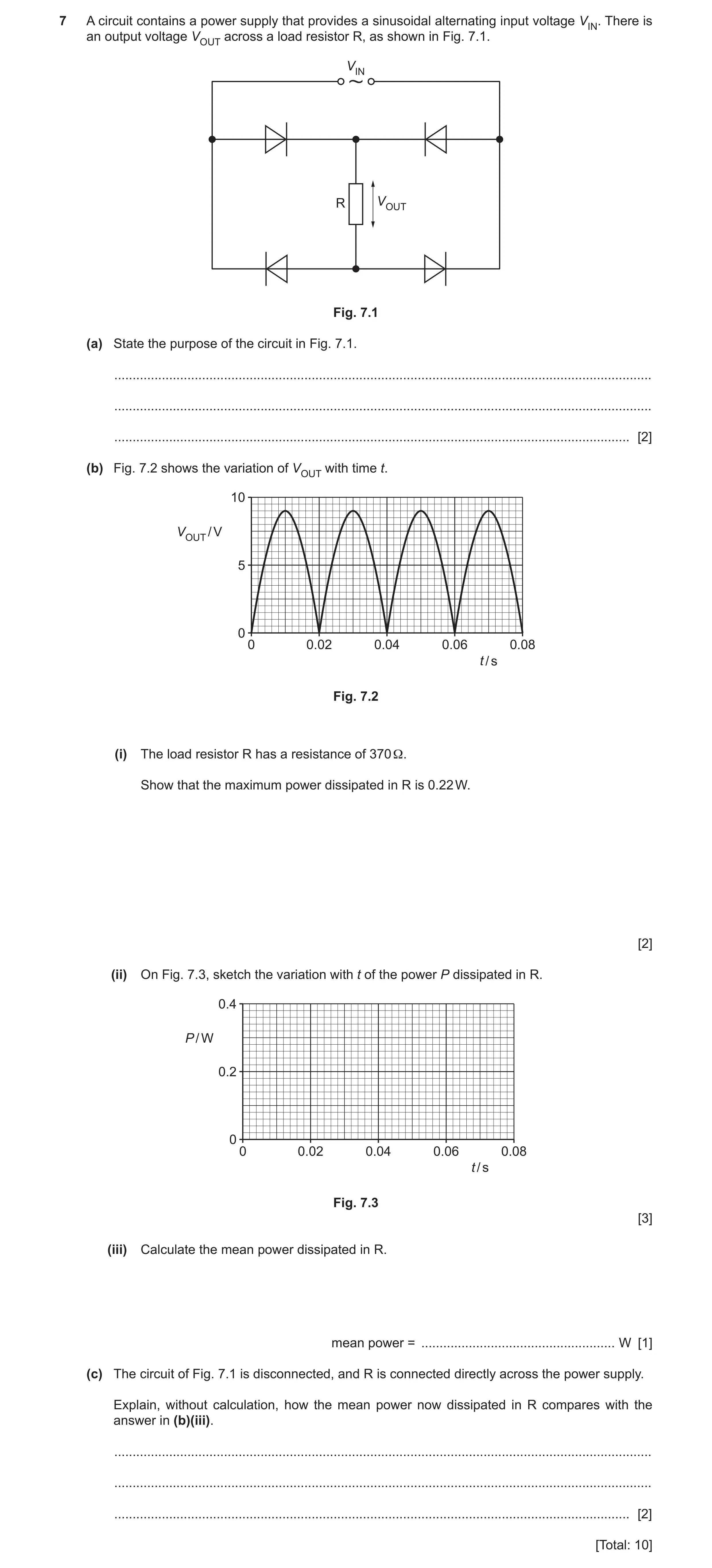
Q36 · A circuit contains a power supply that provides a sinusoidal alternating input voltage VIN 9702/43 May/June 2024
7 A circuit contains a power supply that provides a sinusoidal alternating input voltage VIN. There is an output voltage VOUT across a load resistor R, as shown in Fig. 7.1. VIN R VOUT Fig. 7.1 (a) State the purpose of the circuit in Fig. 7.1. … … … [2] (b) Fig. 7.2 shows the variation of VOUT with time t. 10 VOUT / V 5 0 0 0.02 0.04 0.06 0.08 t / s Fig. 7.2 (i) The load resistor R has a resistance of 370 Ω. Show that the maximum power dissipated in R is 0.22 W. [2] (ii) On Fig. 7.3, sketch the variation with t of the power P dissipated in R. 0.4 P / W 0.2 0 0 0.02 0.04 0.06 0.08 t / s Fig. 7.3 [3] (iii) Calculate the mean power dissipated in R. mean power = … W [1] (c) The circuit of Fig. 7.1 is disconnected, and R is connected directly across the power supply. Explain, without calculation, how the mean power now dissipated in R compares with the answer in (b)(iii). … … … [2] [Total: 10]
10 marks
Mark scheme: 7(a) rectification (of the input voltage) M1 full-wave A1 7(b)(i) P = V2 / R or maximum V = 9.0 V C1 PMAX = 9.02 / 370 = 0.22 W A1 7(b)(ii) sinusoidal shape with minima sitting on the time axis B1 correct frequency and phase, with minima at 0, 0.02, 0.04, 0.06 and 0.08 s and maxima at 0.01, 0.03, 0.05 and 0.07 s B1 all maxima shown at 0.22 W B1 7(b)(iii) mean power = peak power / 2 = 0.22 / 2 = 0.11 W A1 7(c) power–time graph is identical B1 (so) mean powers are equal B1
This question in 9702/43 May/June 2024
 1 / 49
 2 / 49
 3 / 49
 4 / 49
 5 / 49
 6 / 49
 7 / 49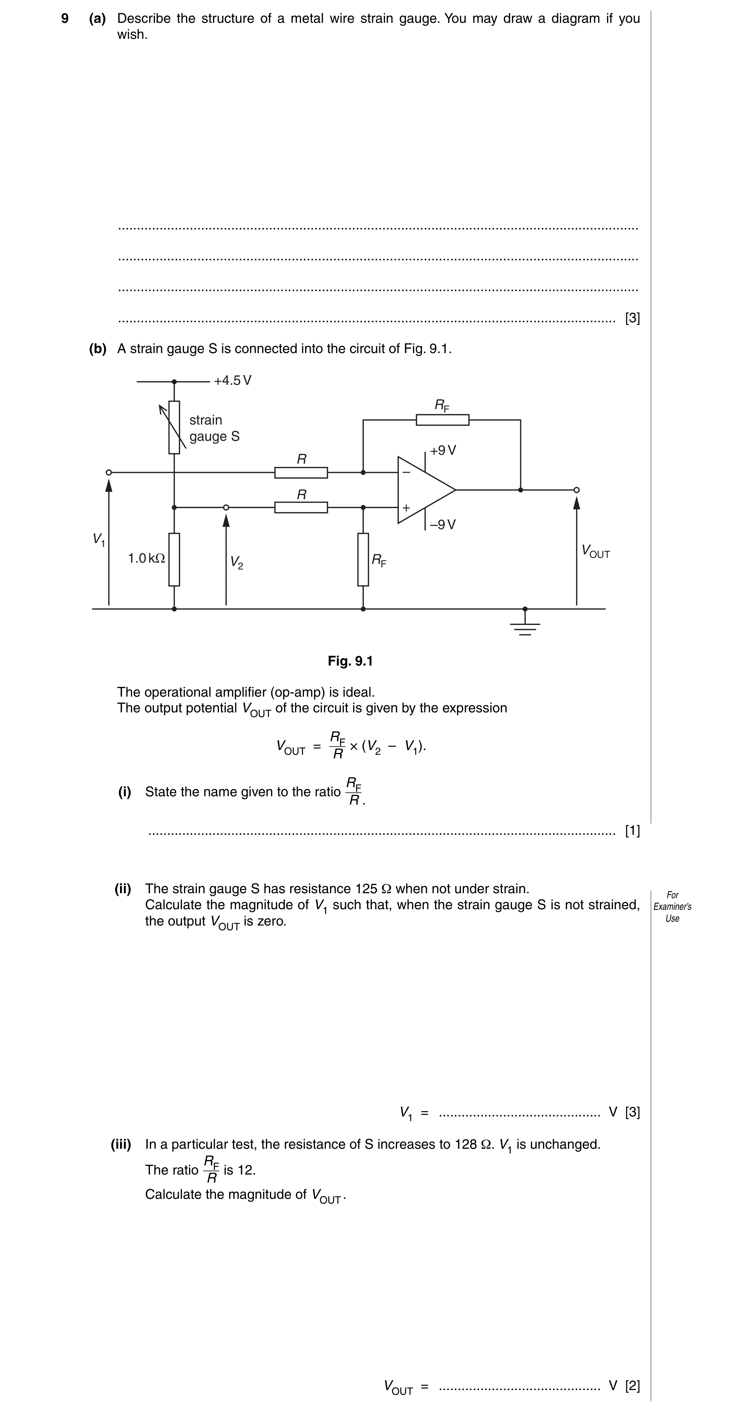
 18 / 49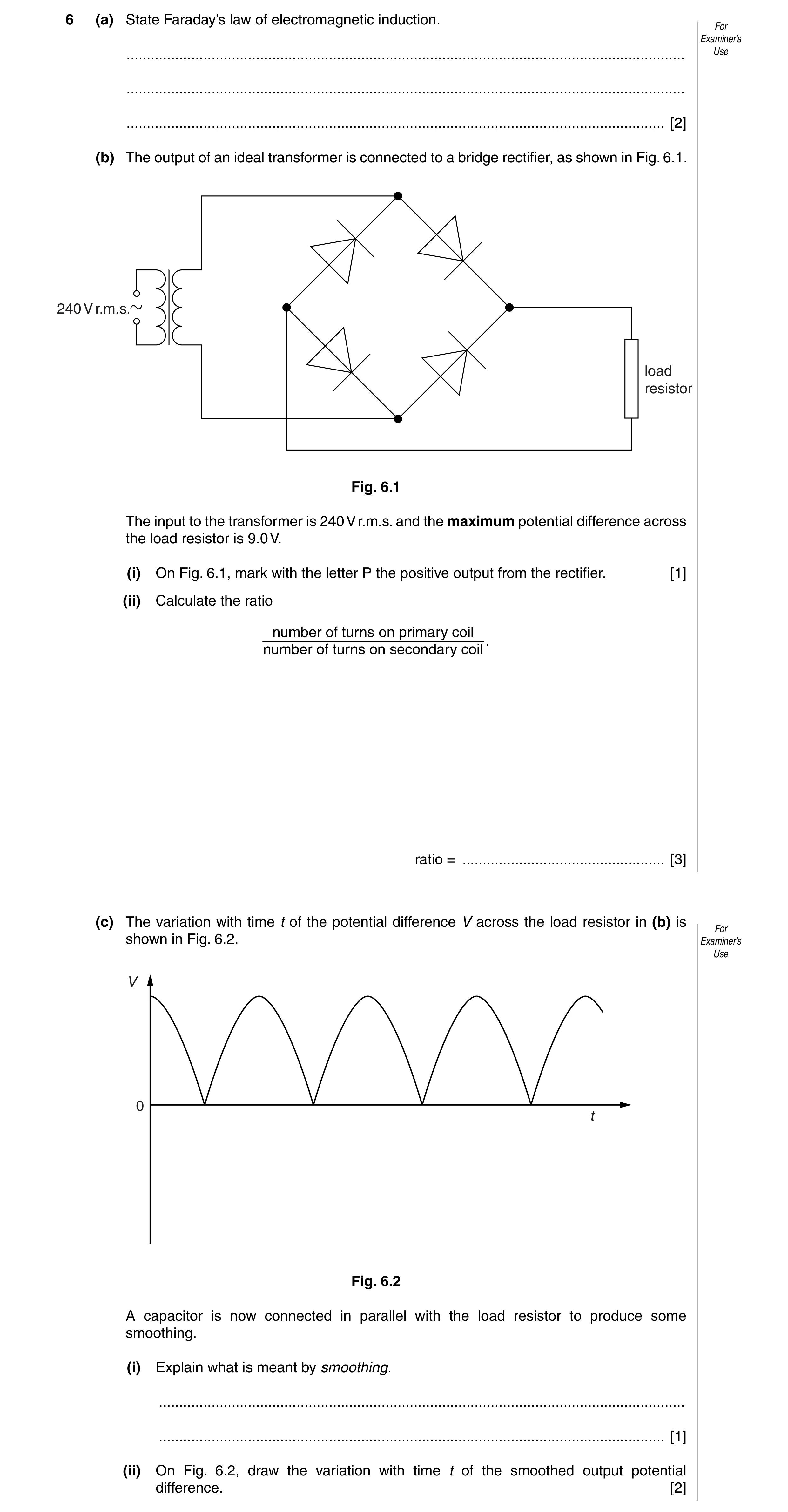
 21 / 49
 22 / 49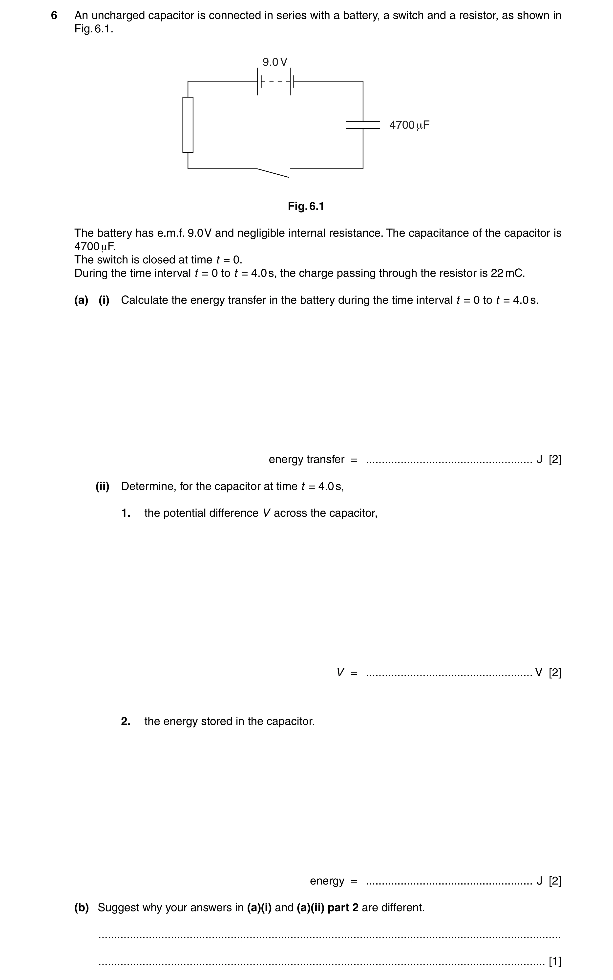
 26 / 49
 27 / 49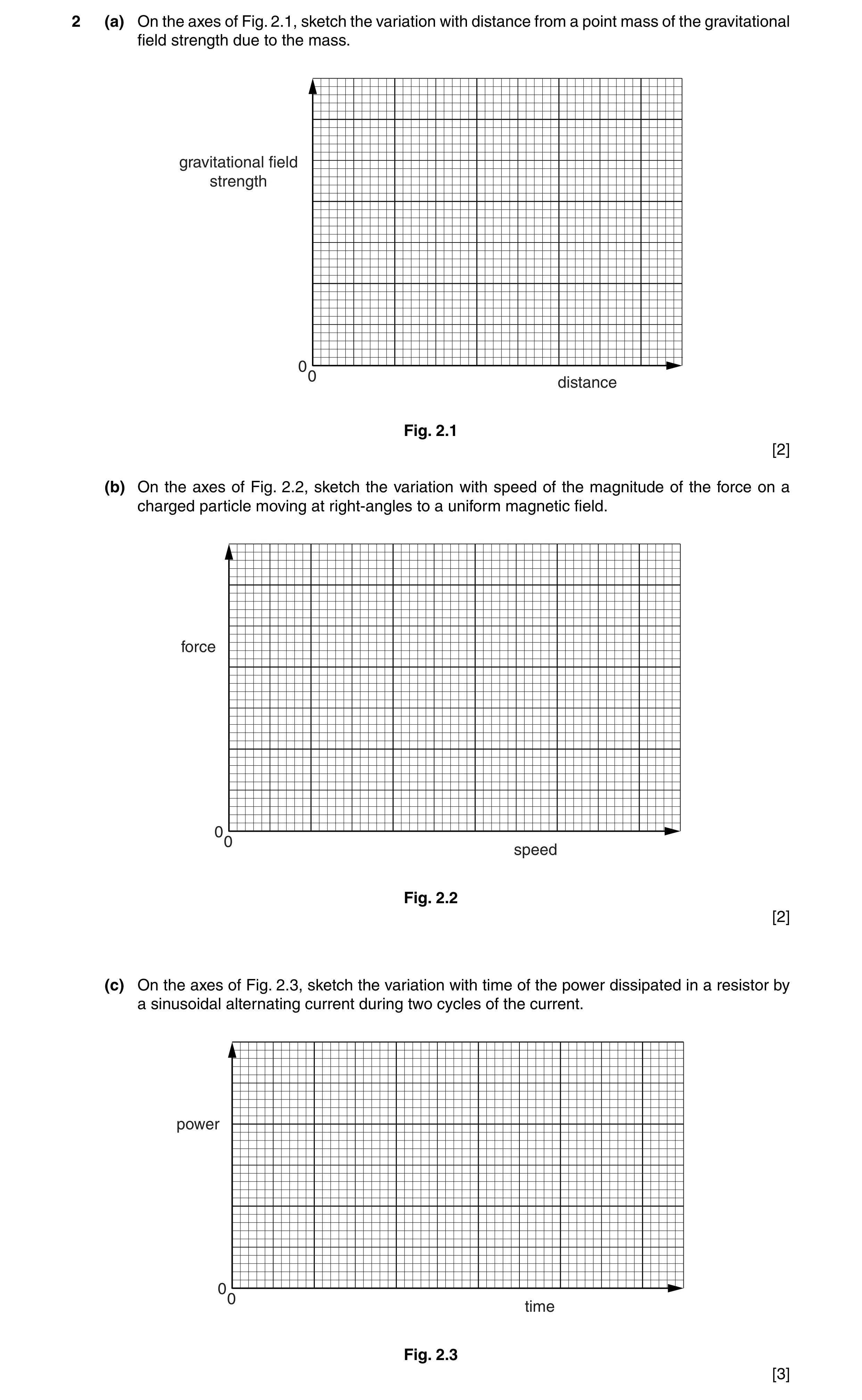
 29 / 49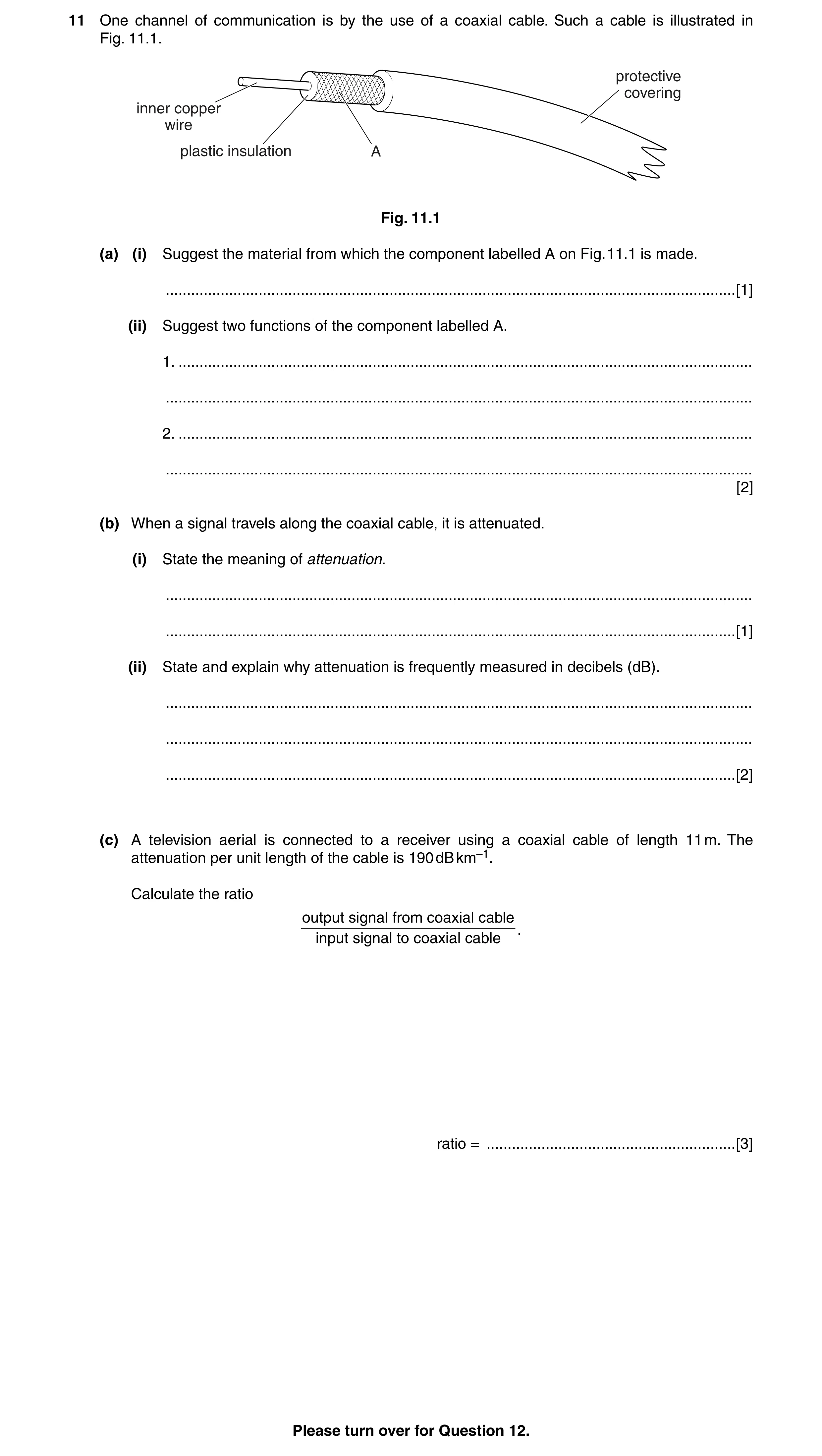
 31 / 49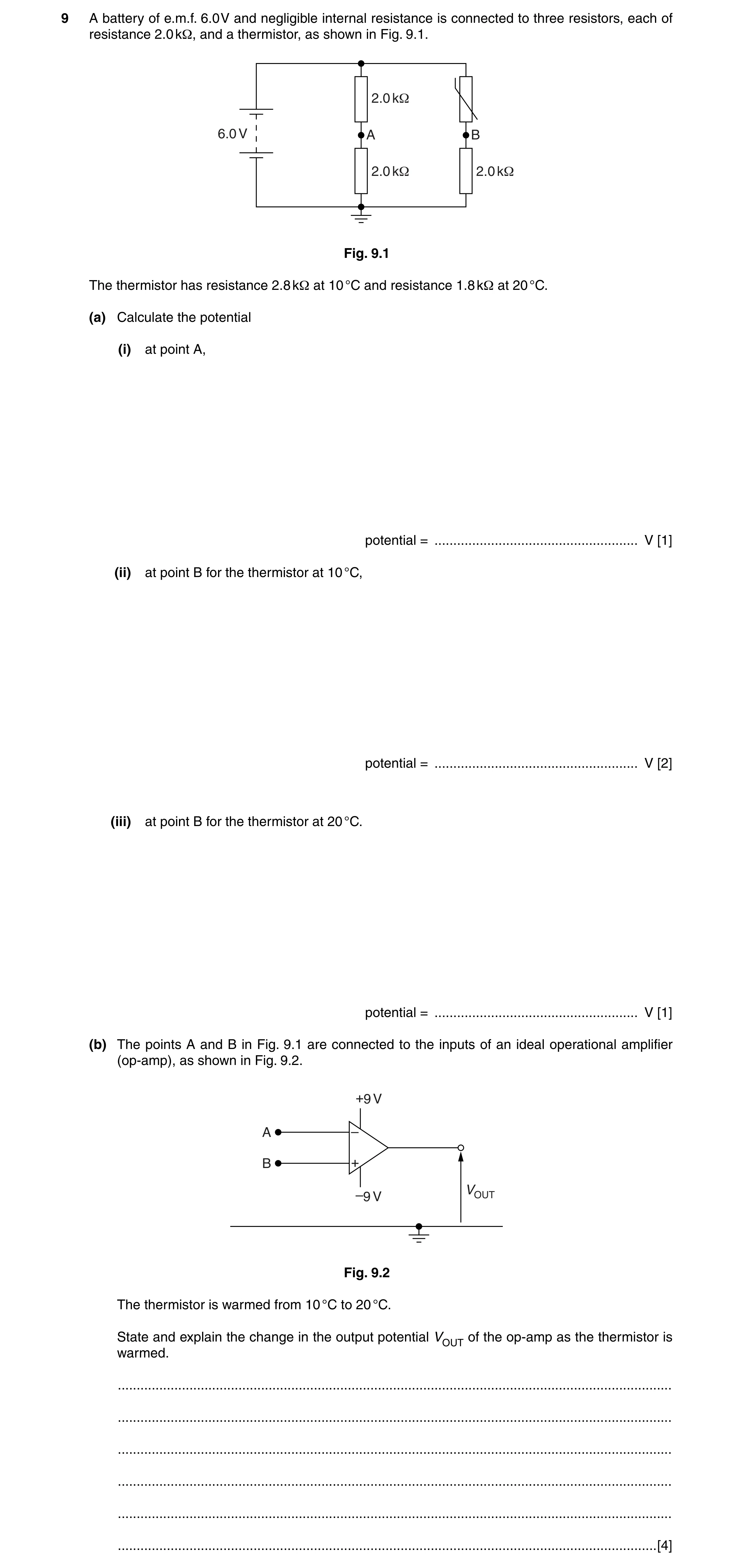
 39 / 49
 40 / 49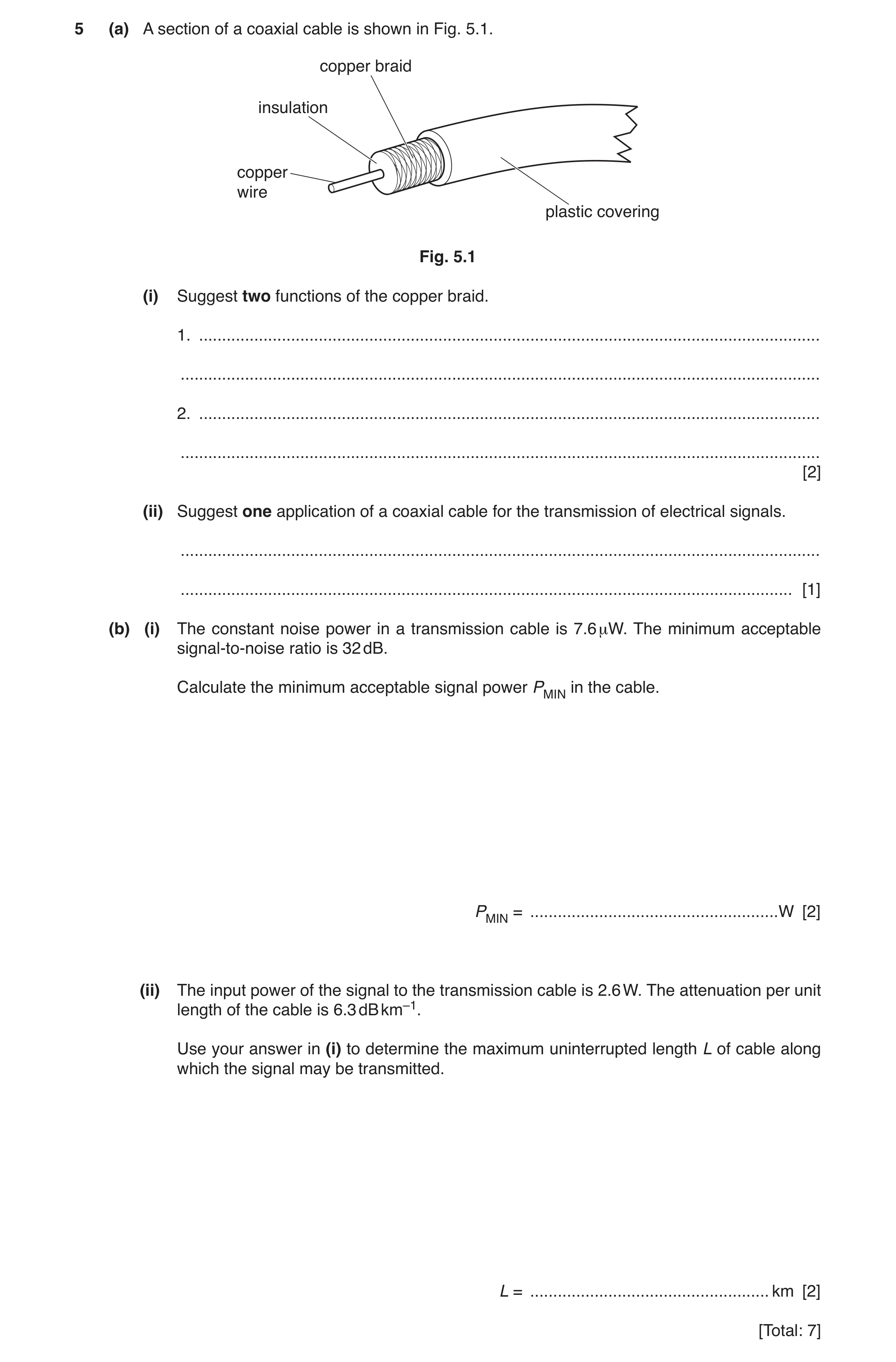
 5
5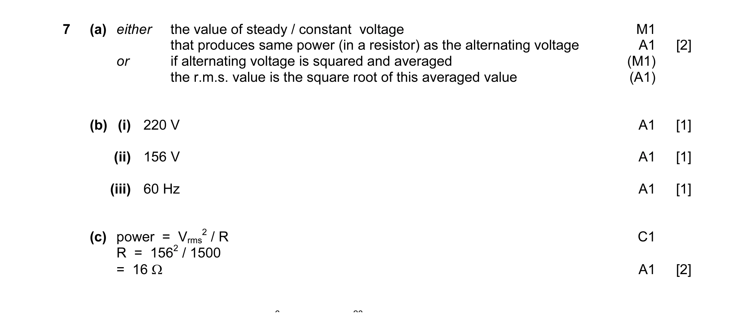 7
7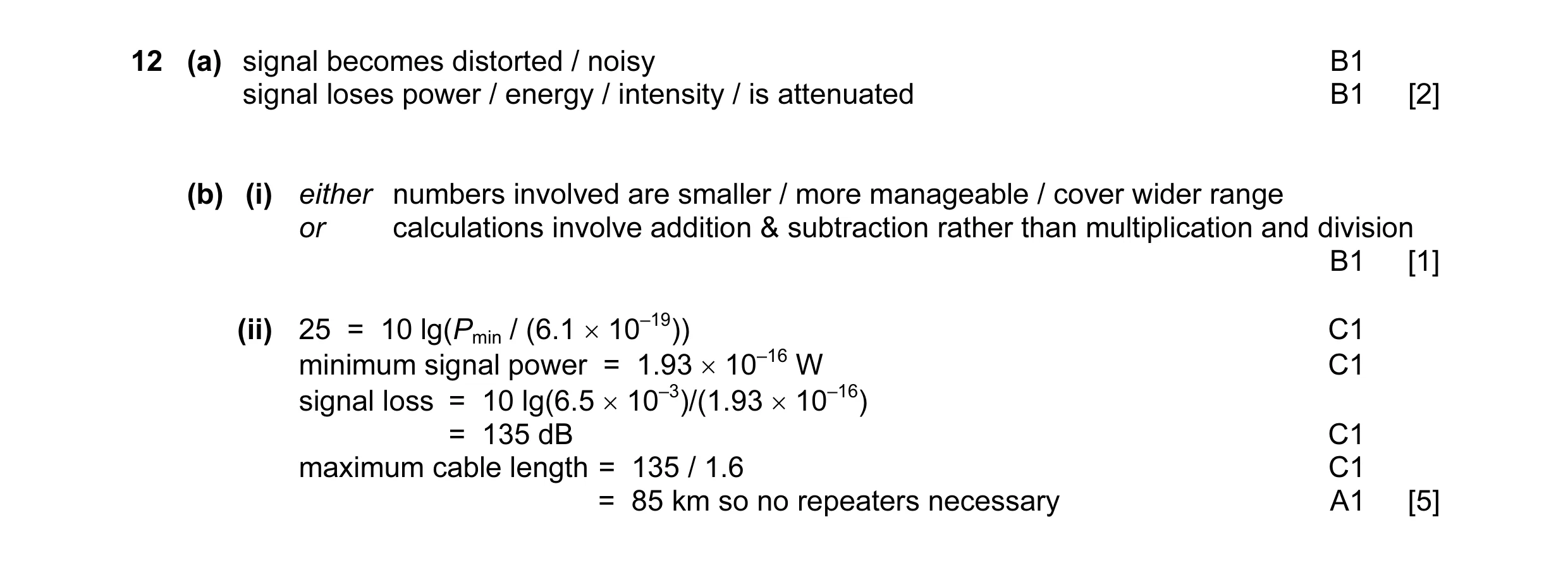 8
8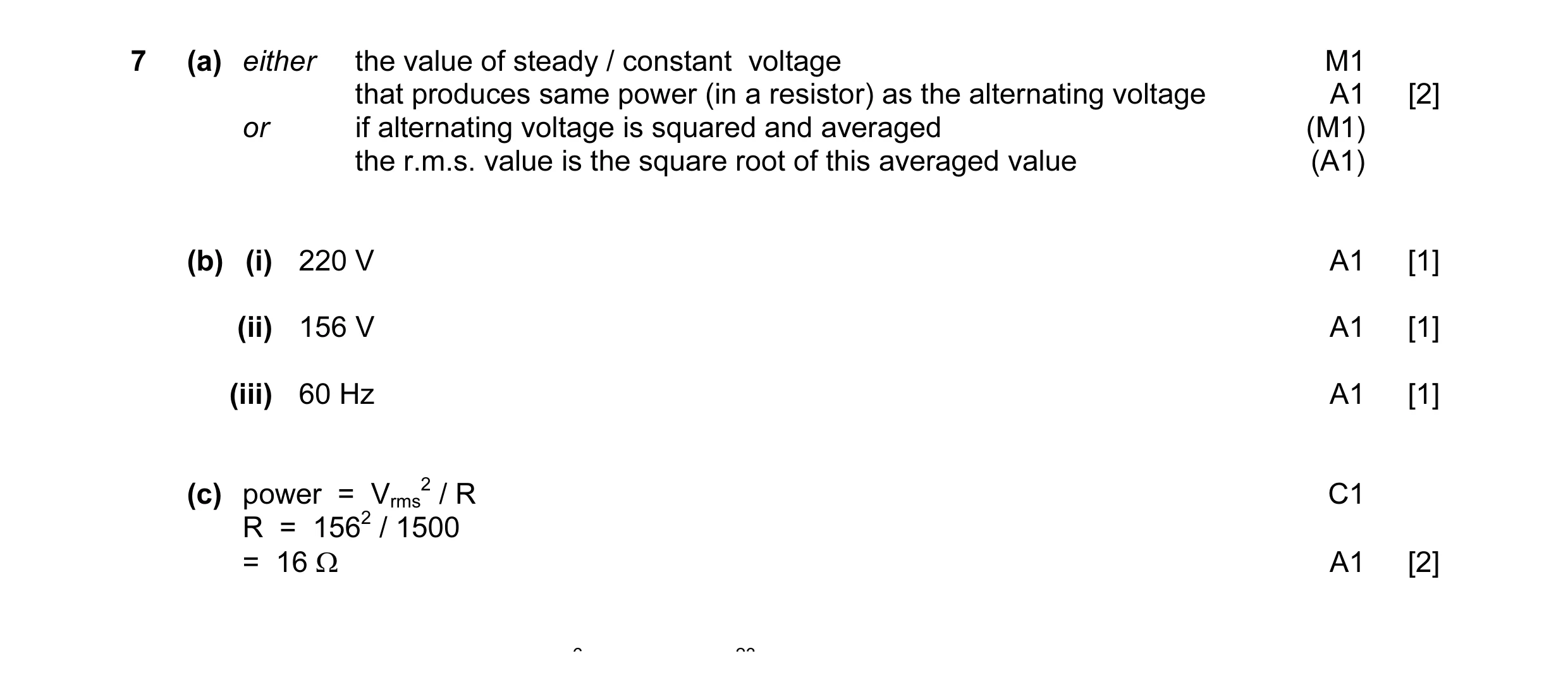 7
7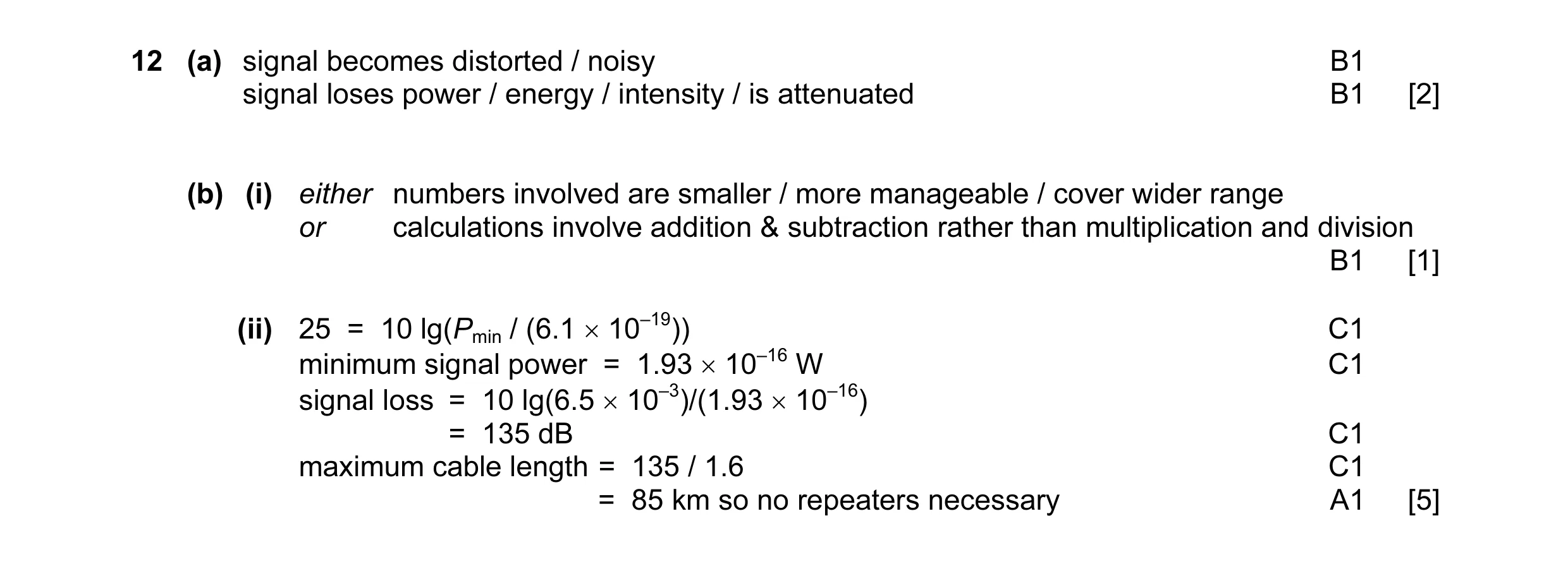 8
8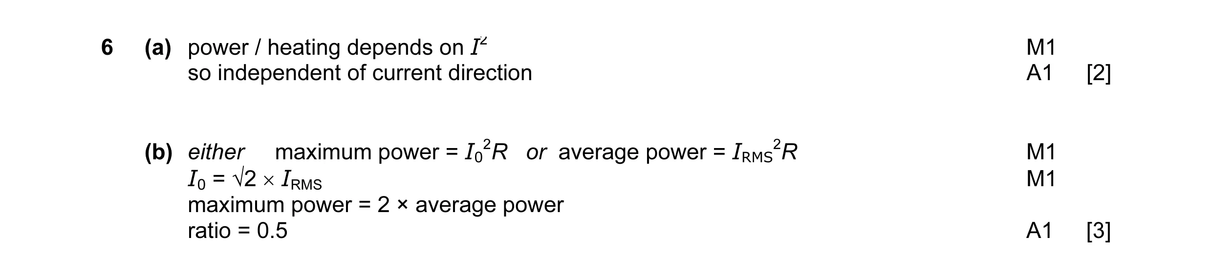 5
5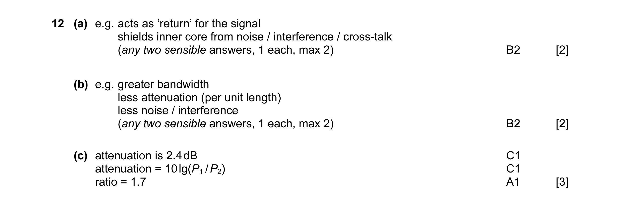 4
4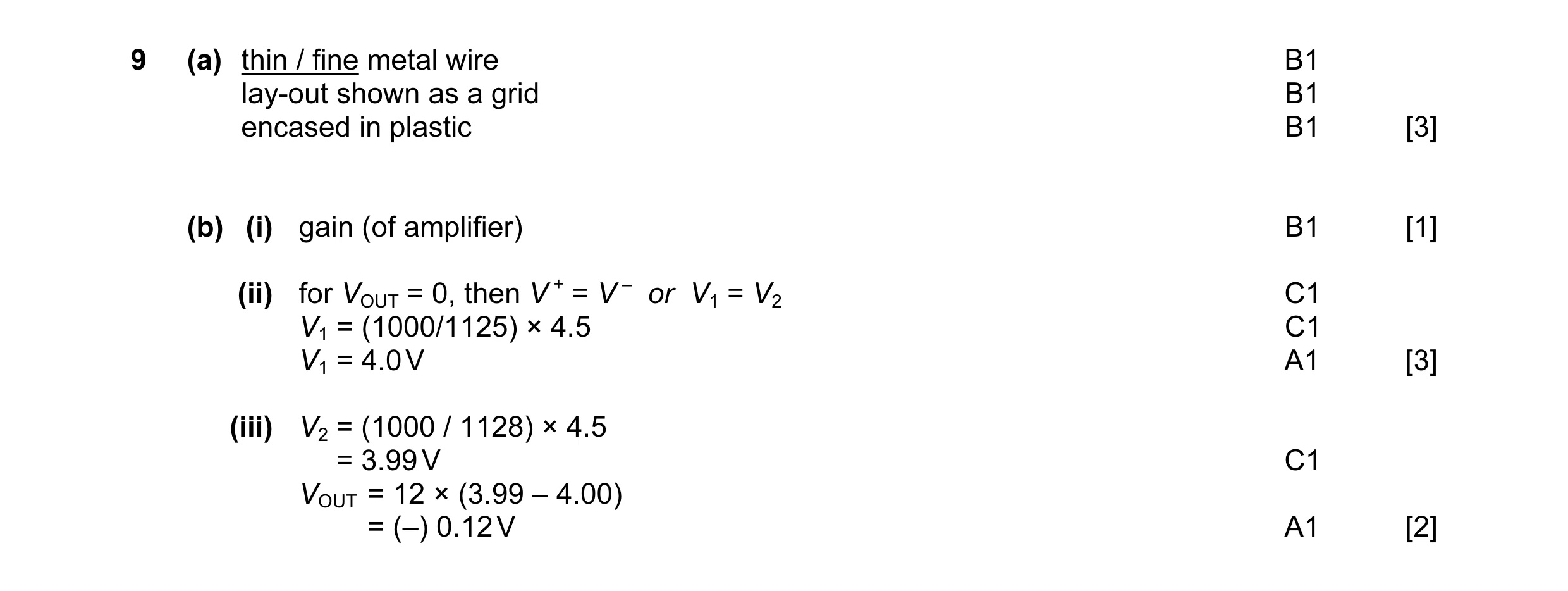 9
9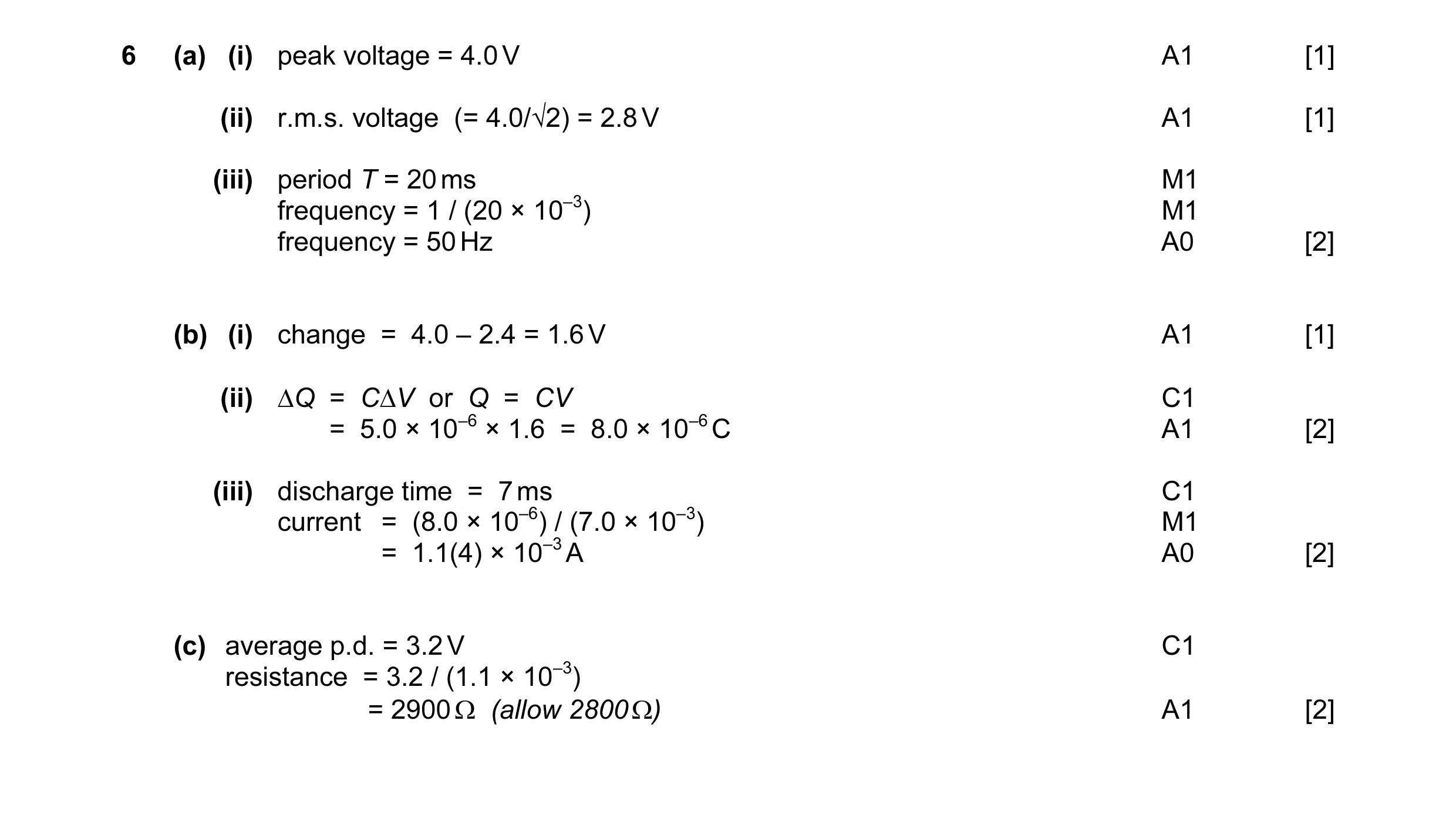 11
11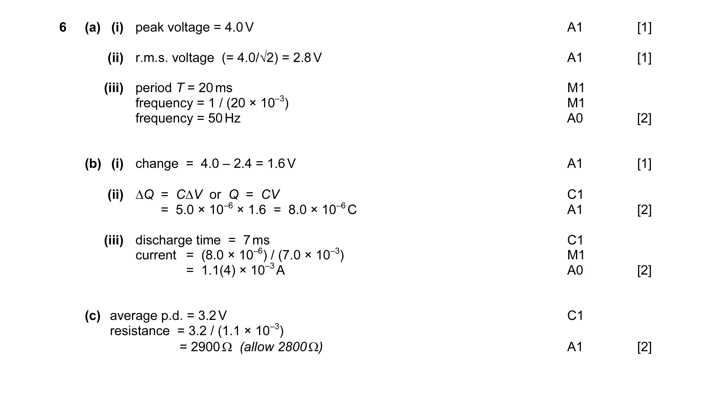 11
11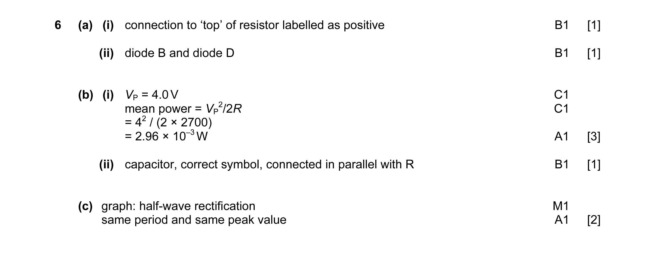 8
8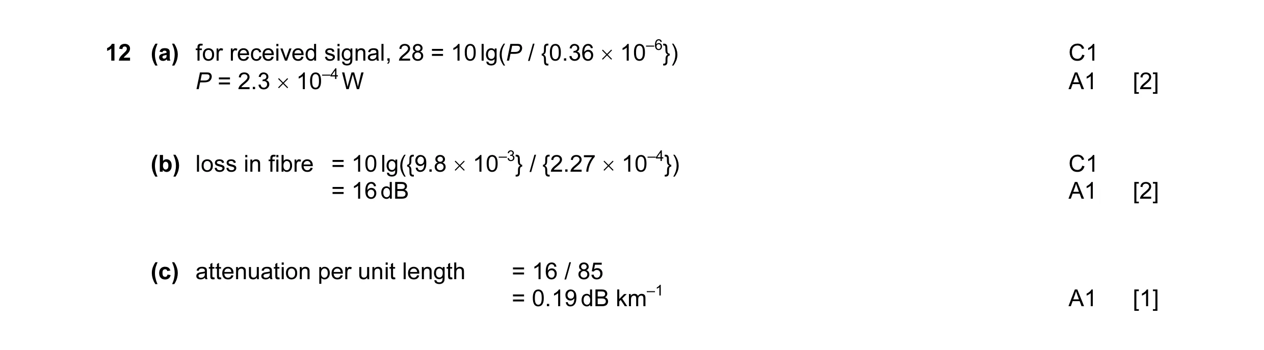 4
4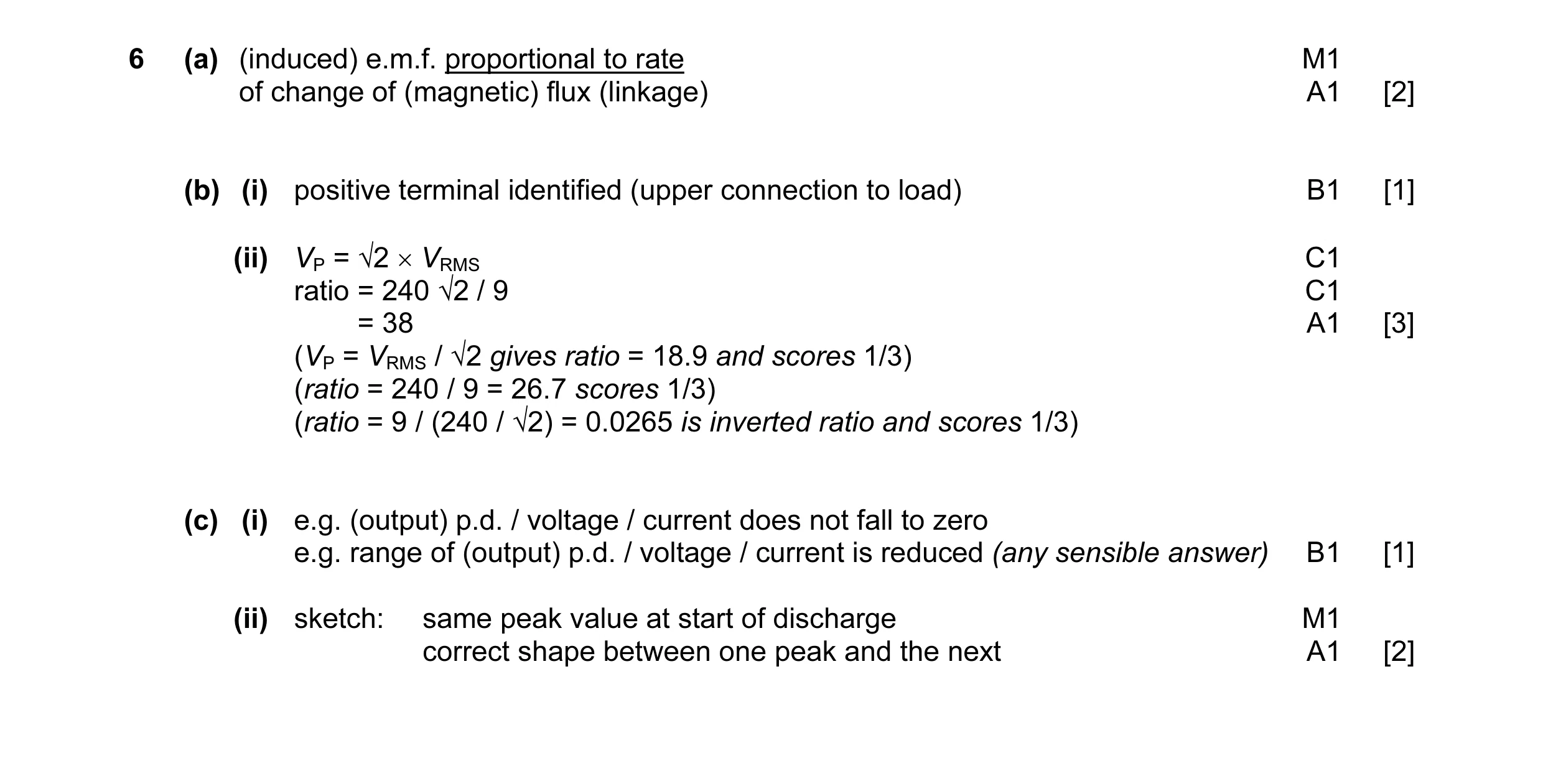 9
9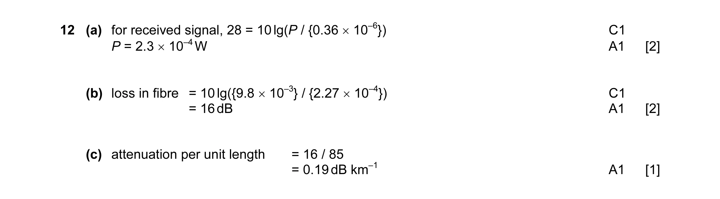 4
4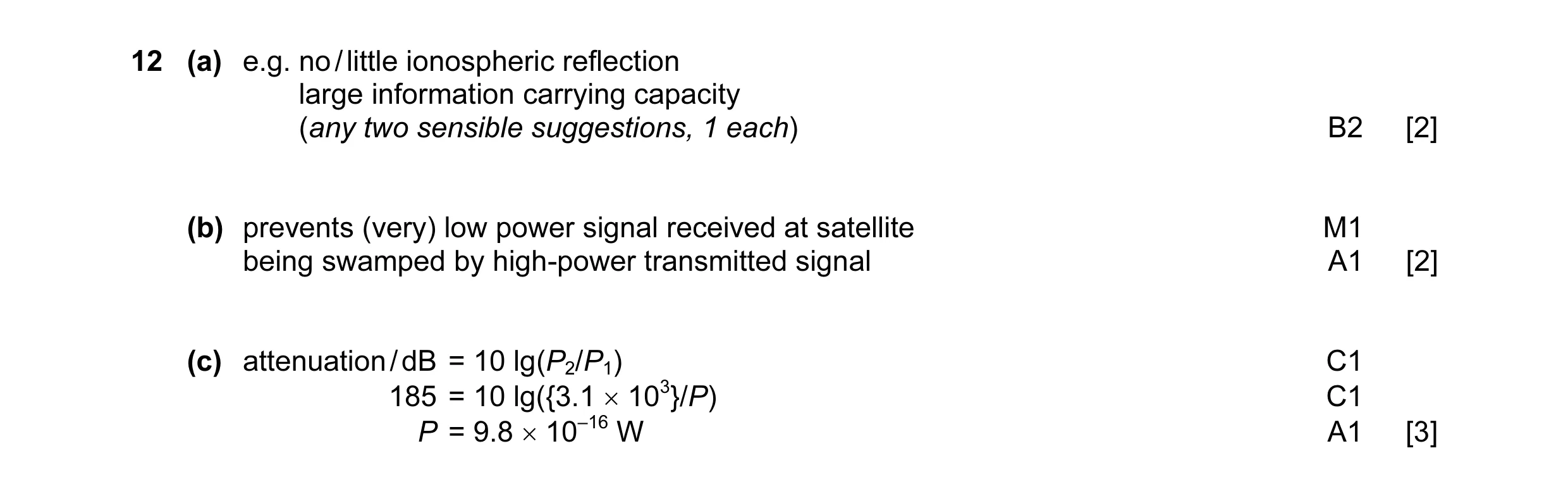 7
7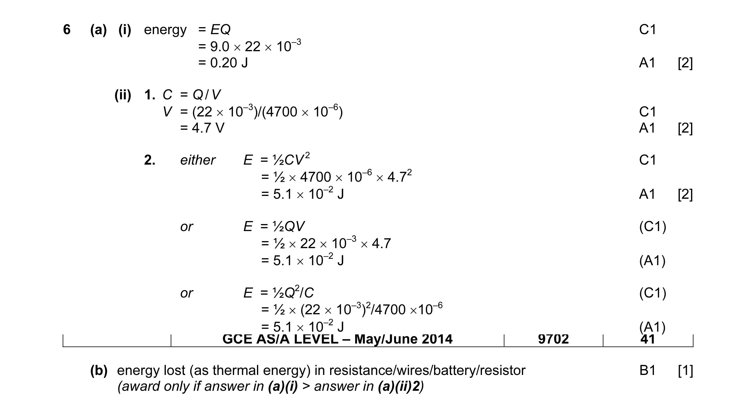 7
7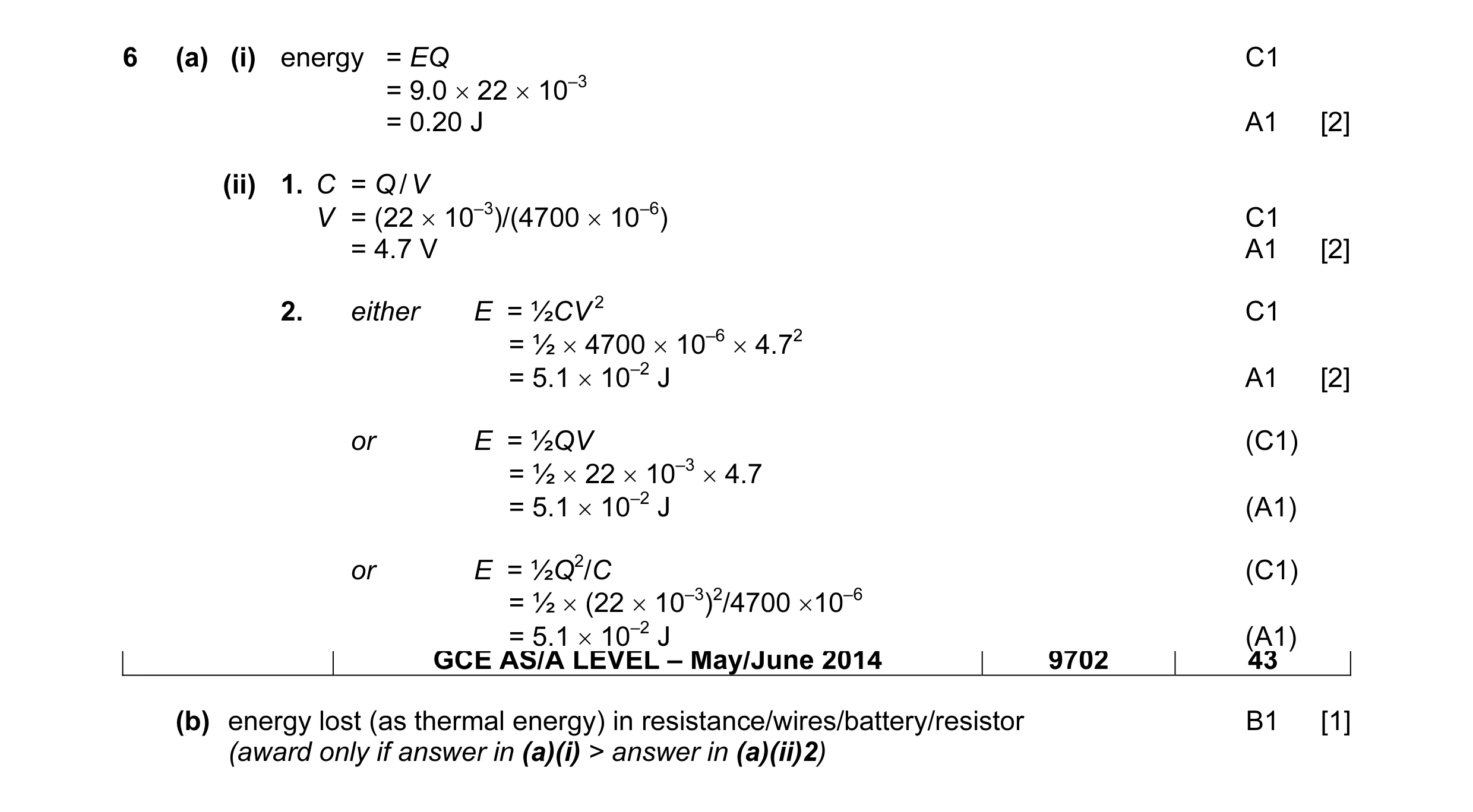 7
7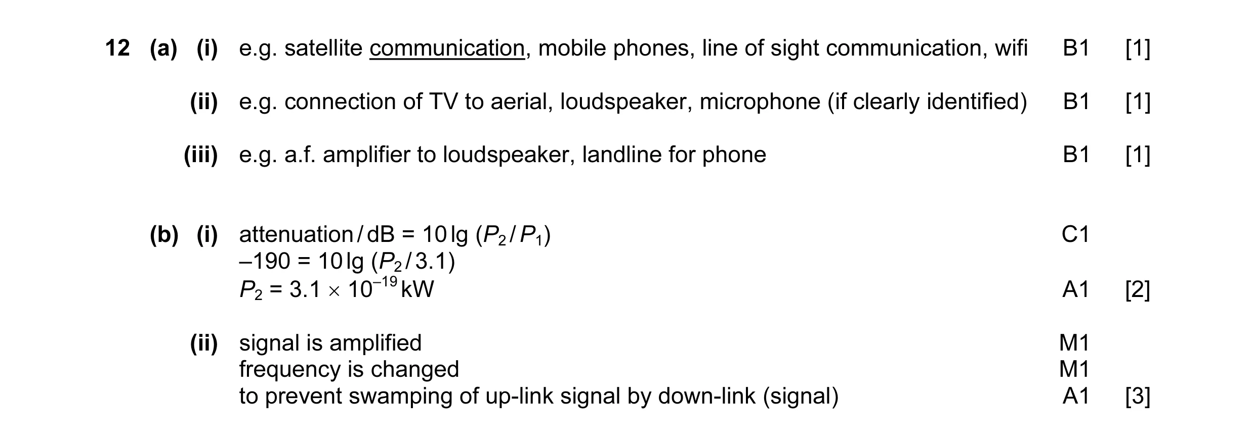 8
8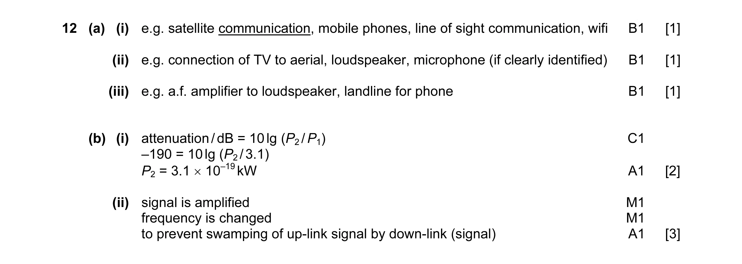 8
8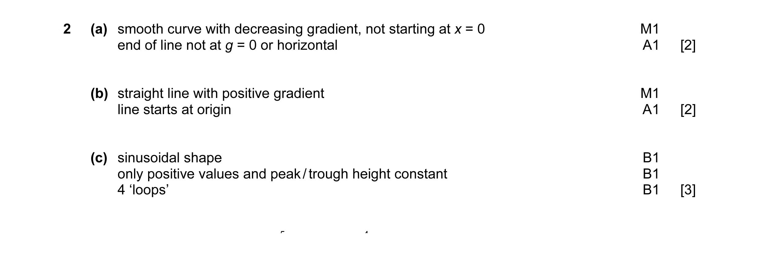 7
7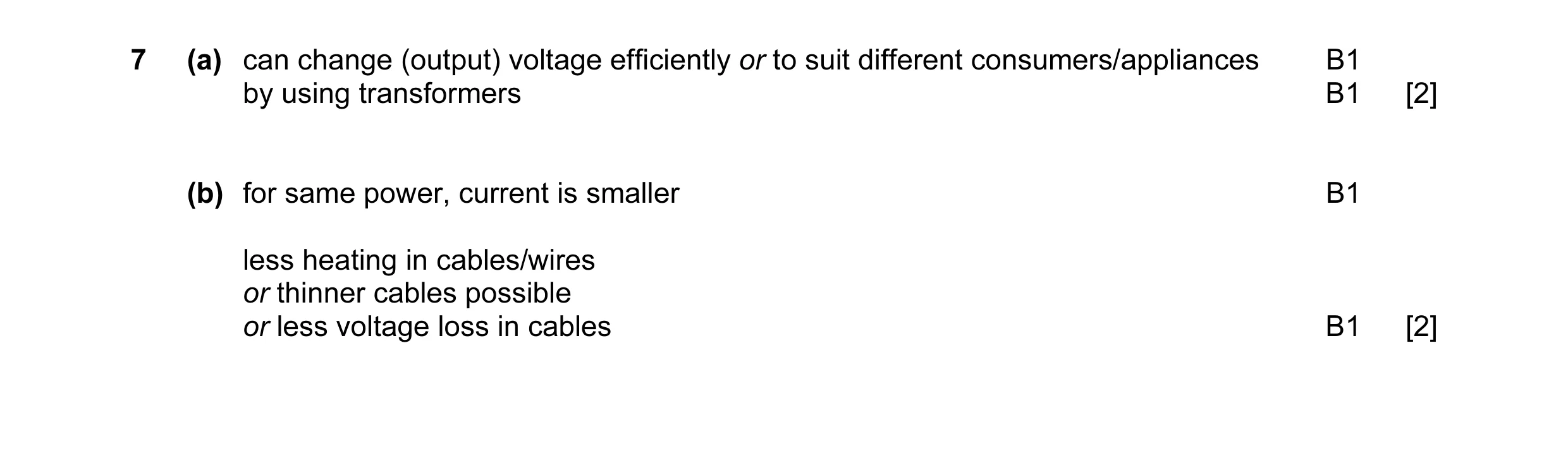 4
4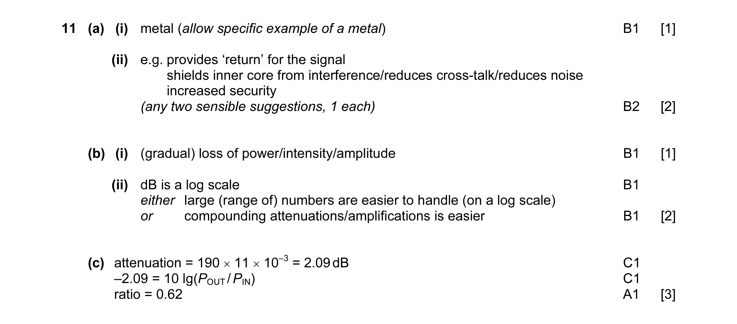 9
9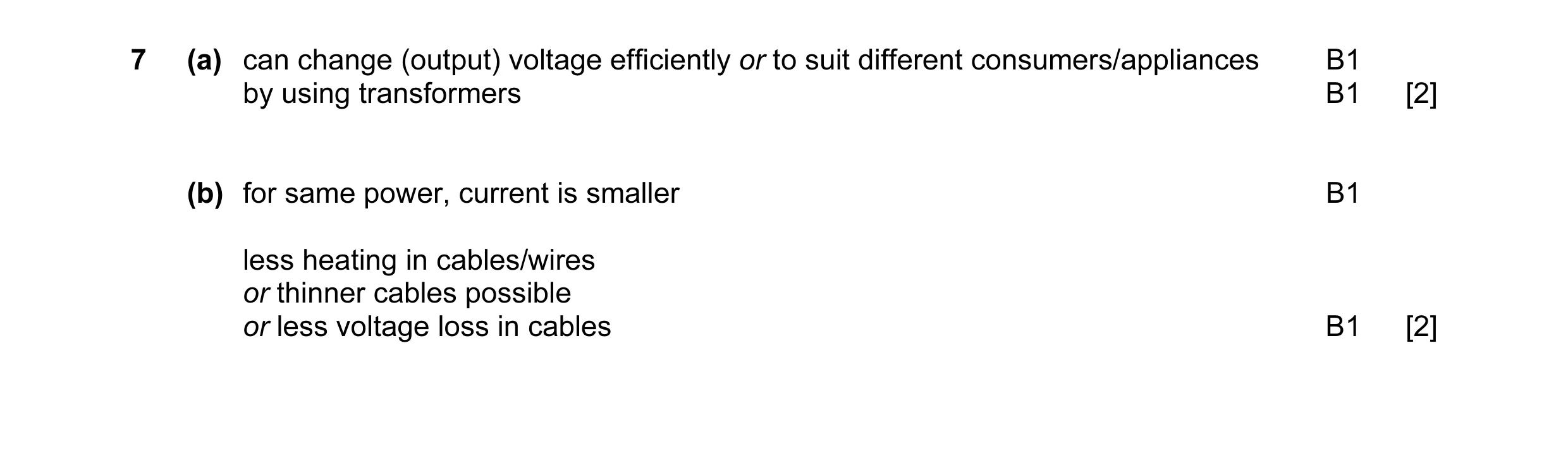 4
4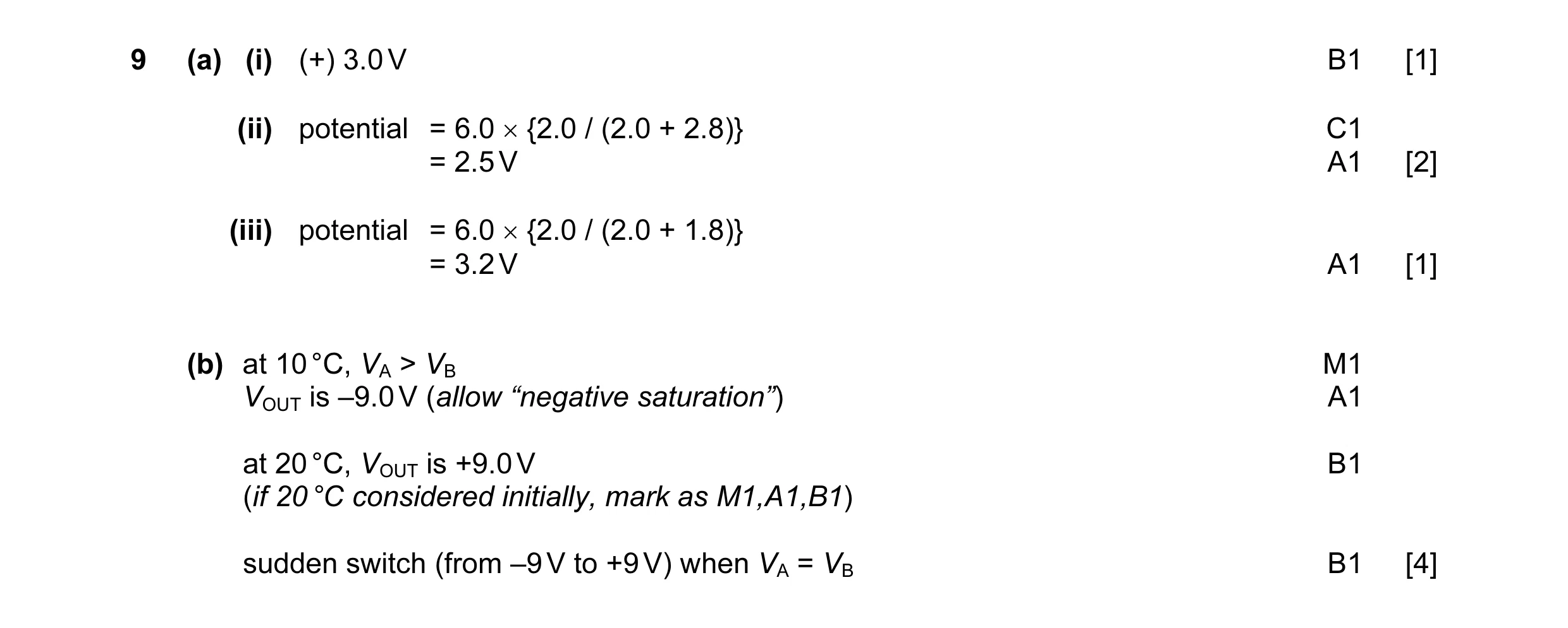 8
8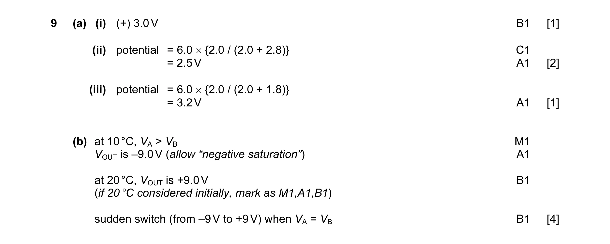 8
8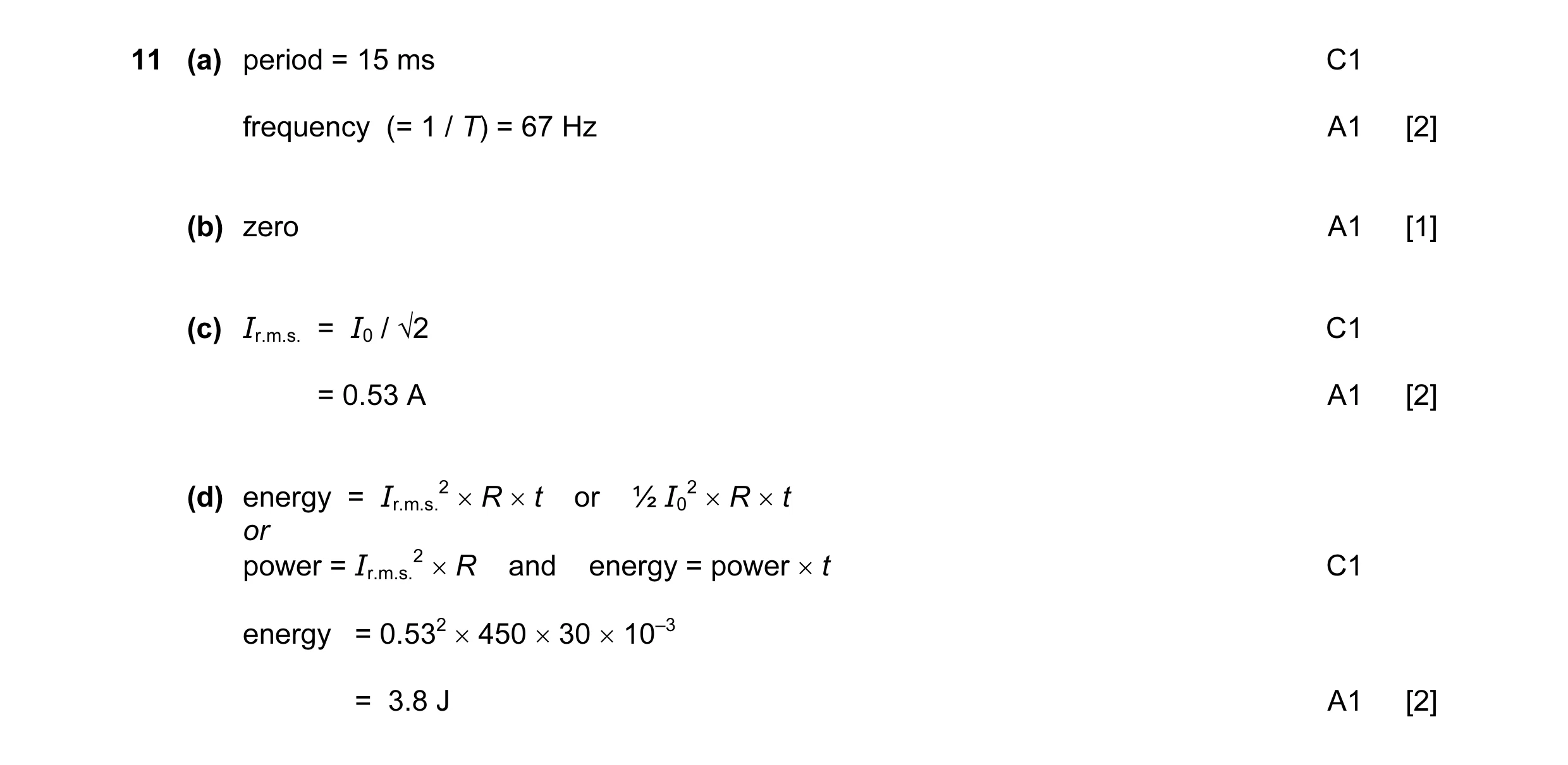 7
7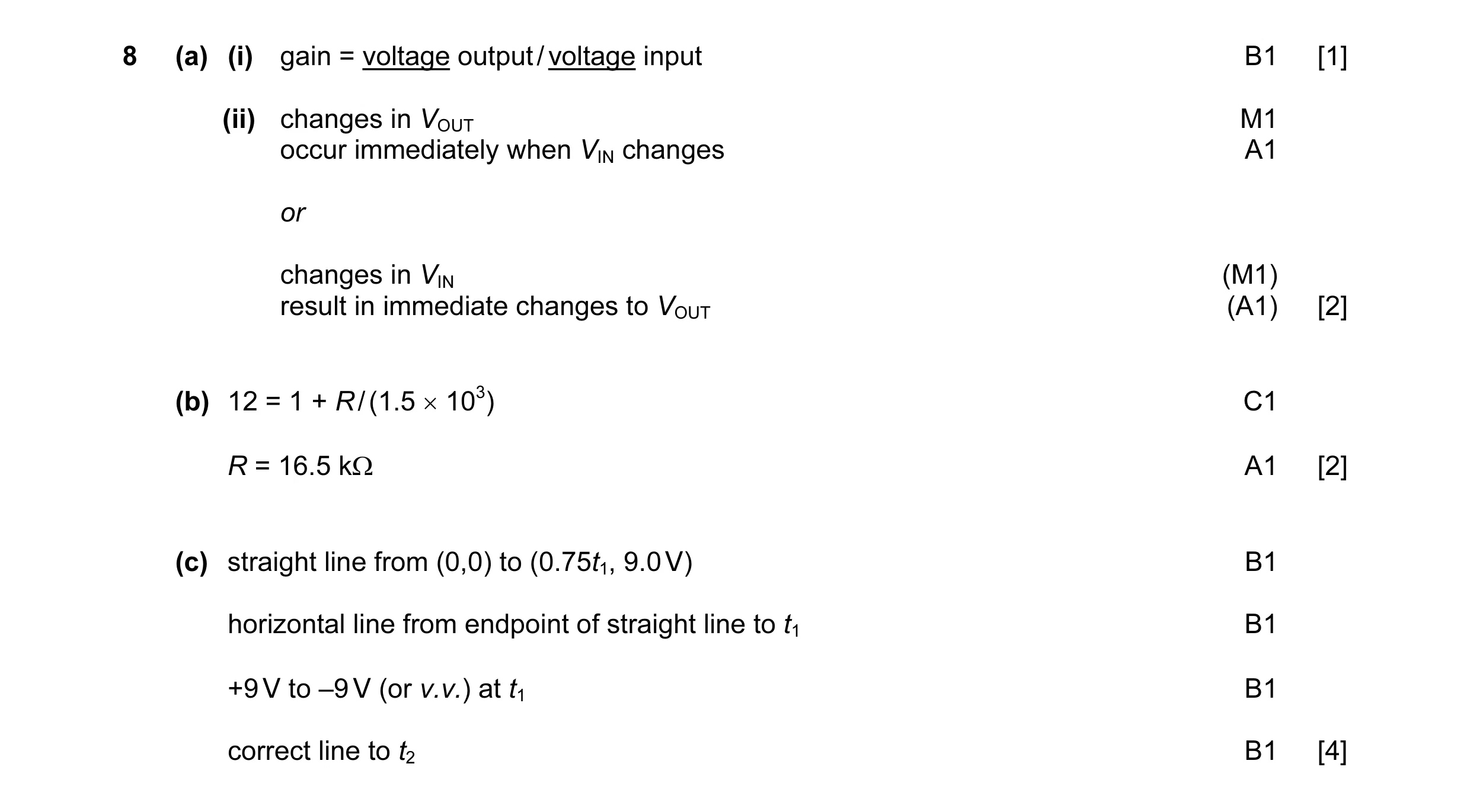 9
9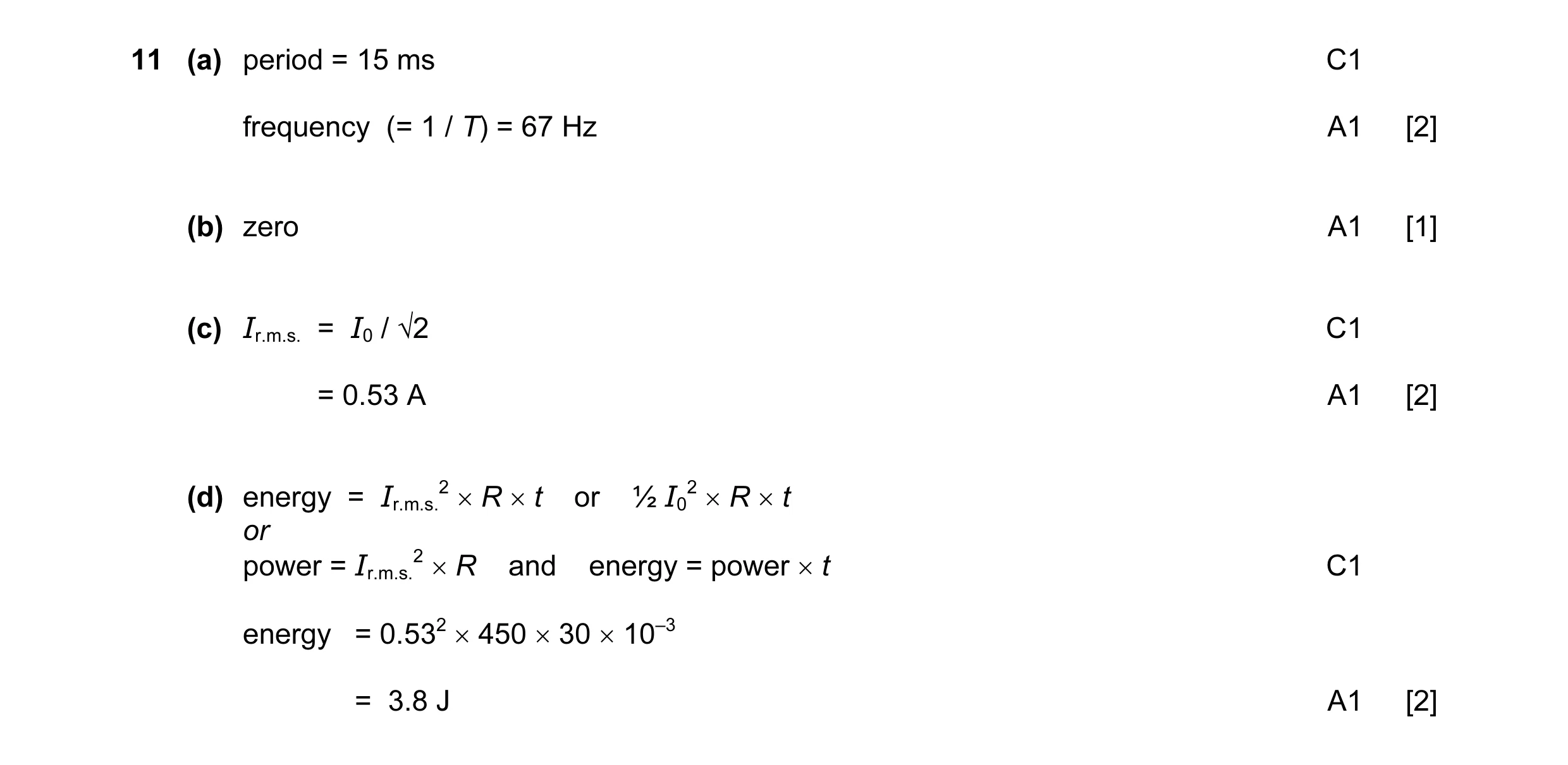 7
7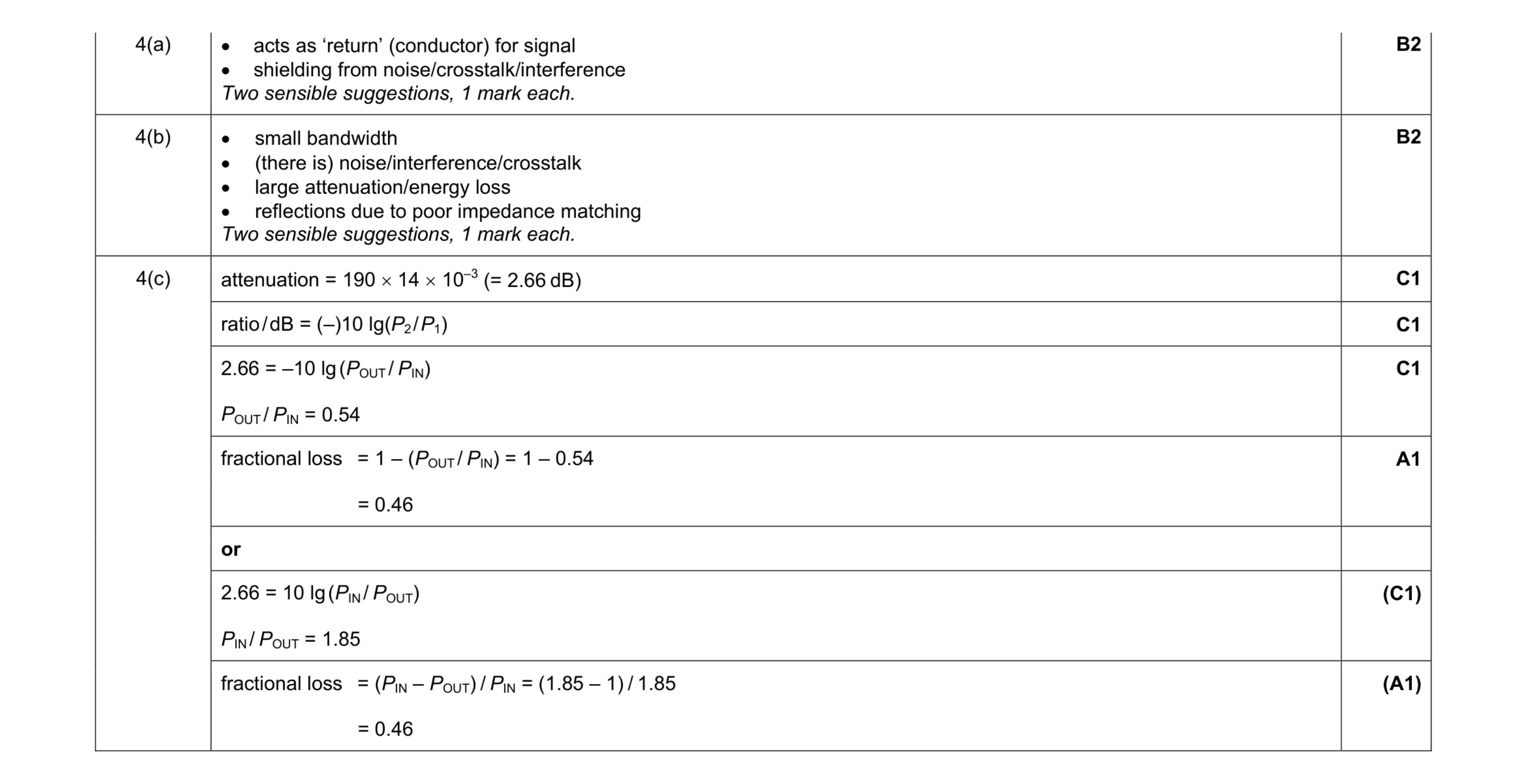 8
8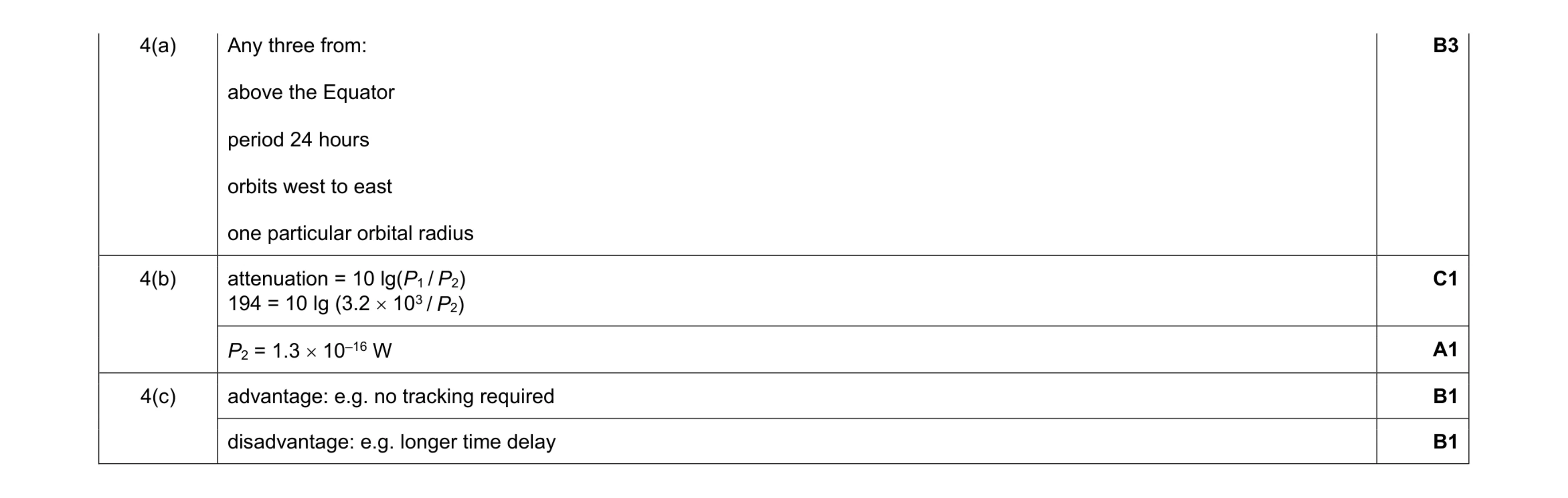 7
7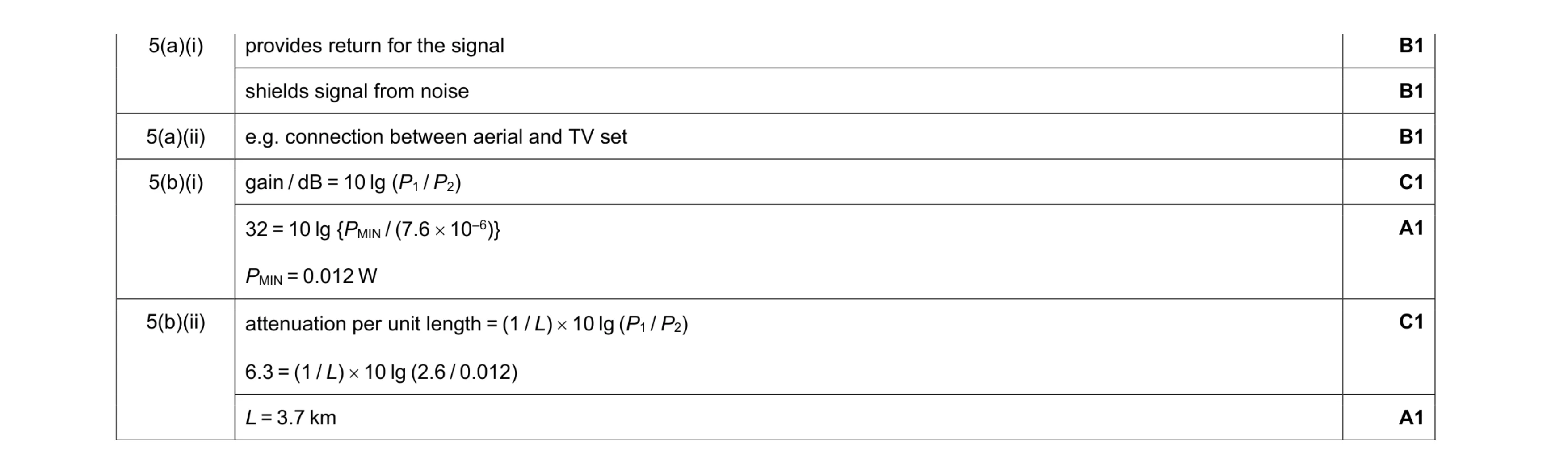 7
7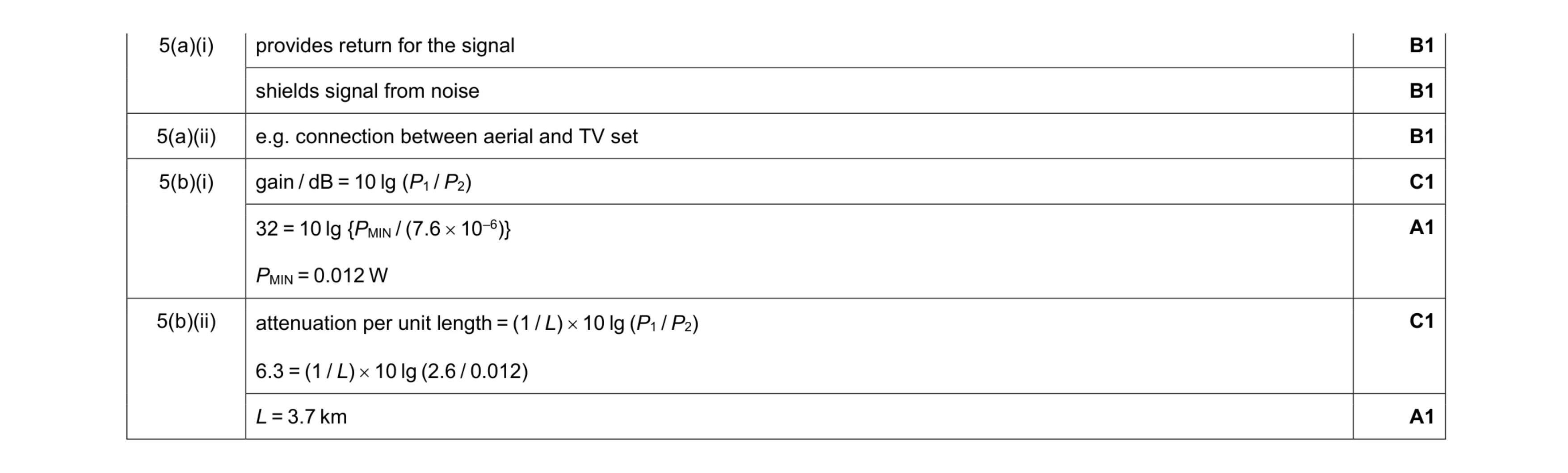 7
7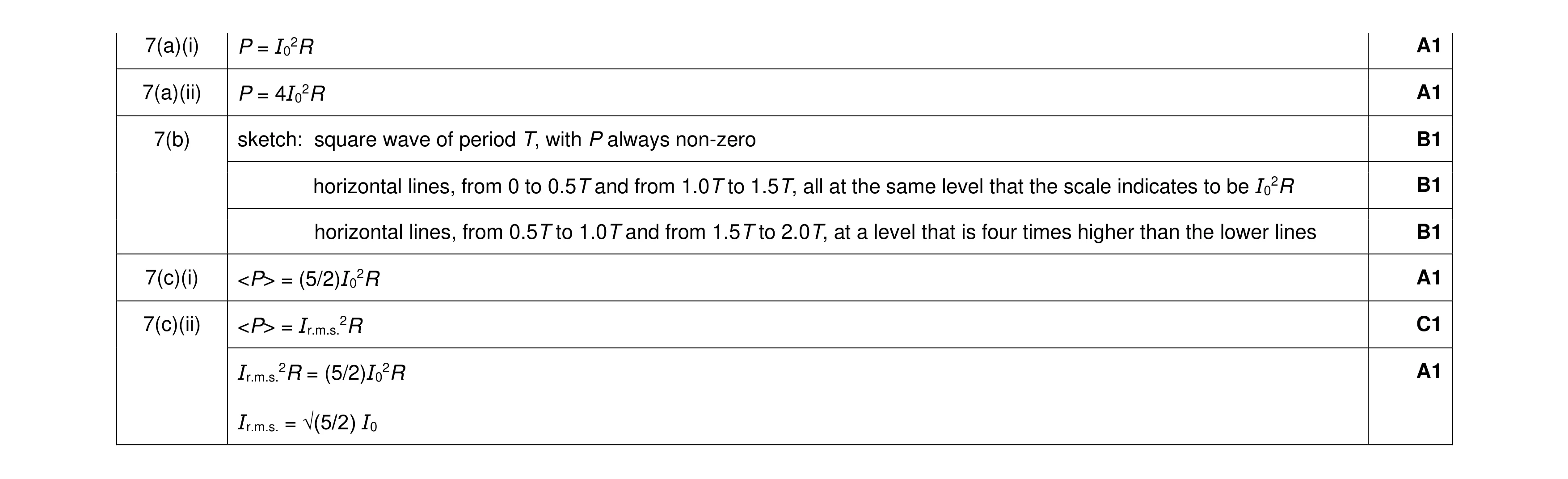 8
8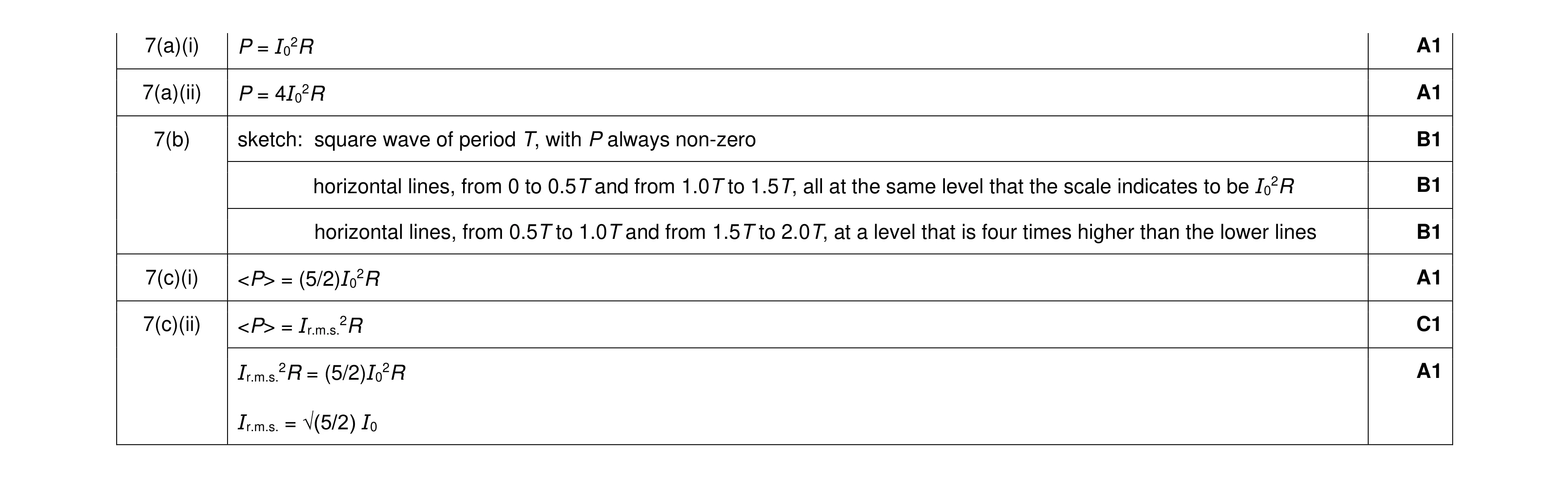 8
8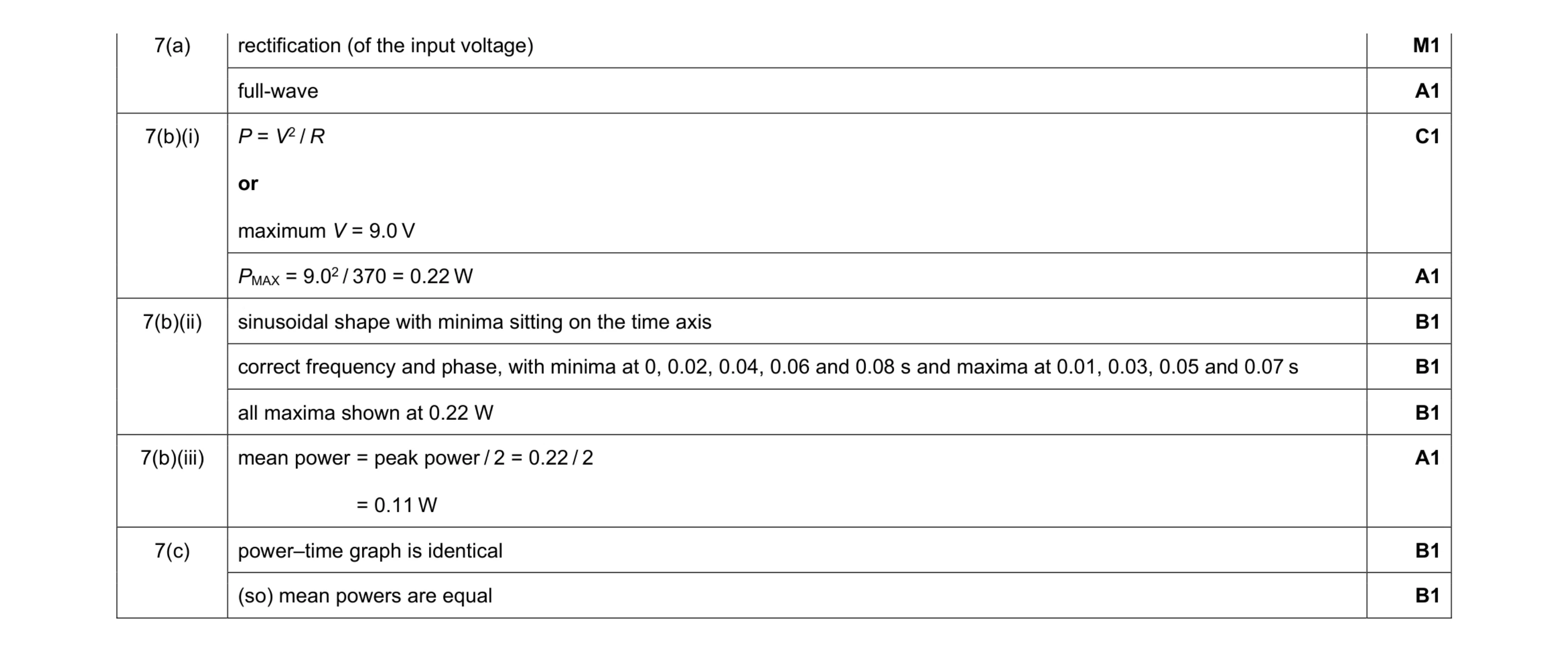 10
10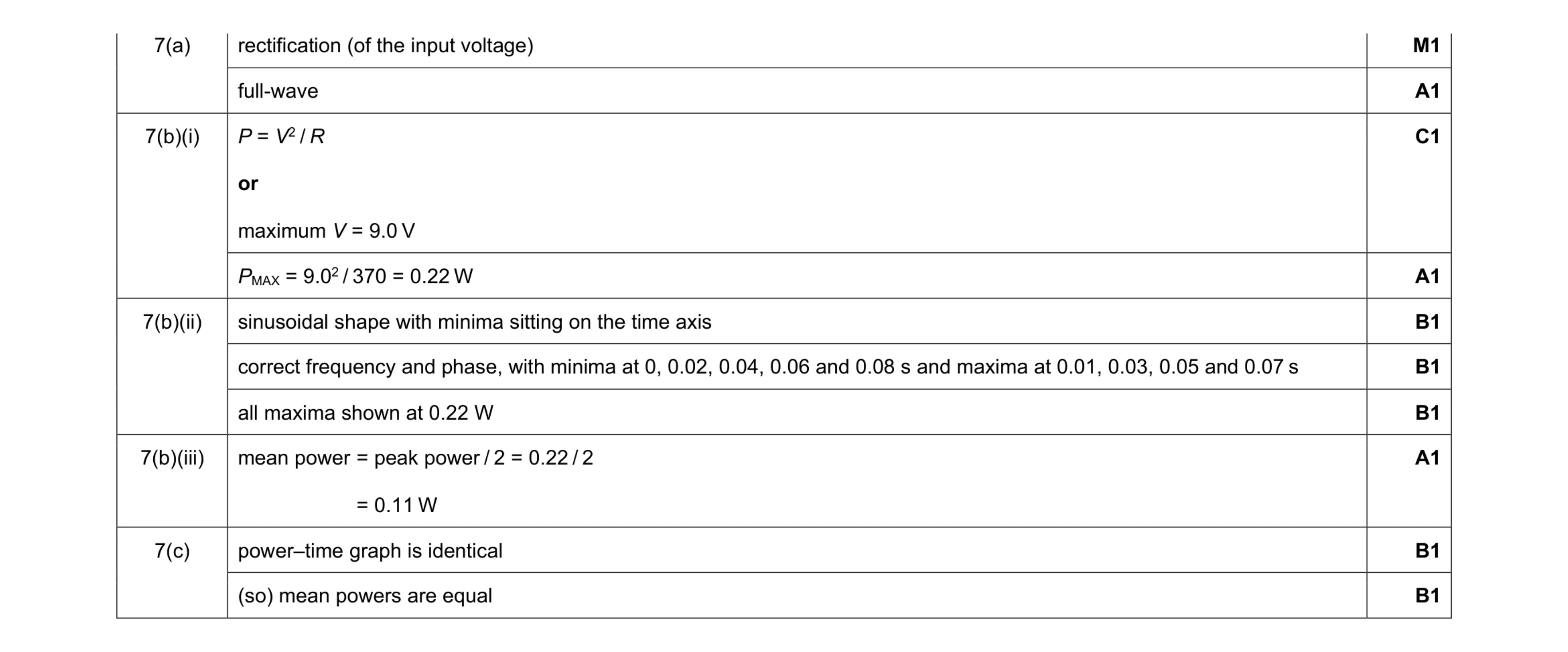 10
10