Cambridge A Level Physics 9702 — 2015 May/June Paper 4 · Variant 2
9702/42/M/J/15 · 12 questions · 100 marks · ≈113 min
The question paper and its mark scheme, free to read here and free to download. This is Cambridge’s own paper, exactly as it was sat.
Question paper24 pages
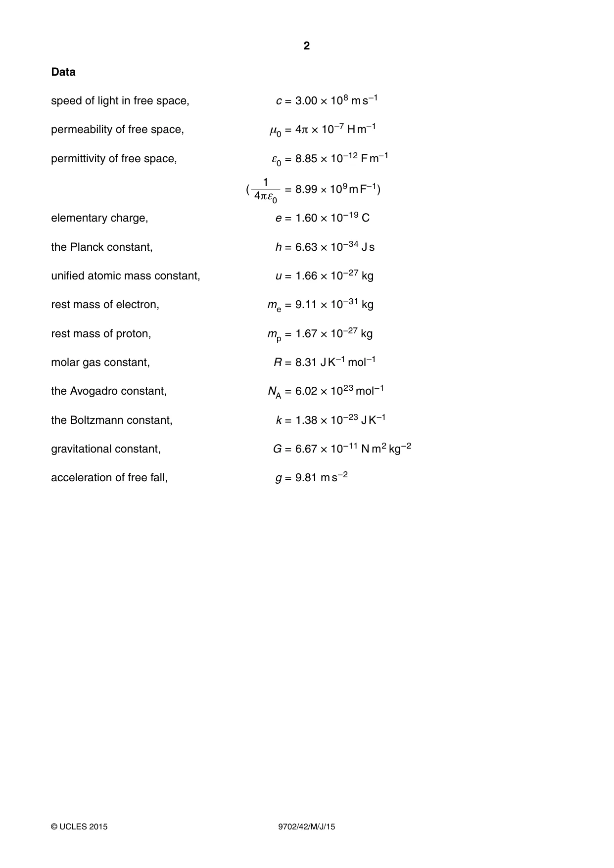
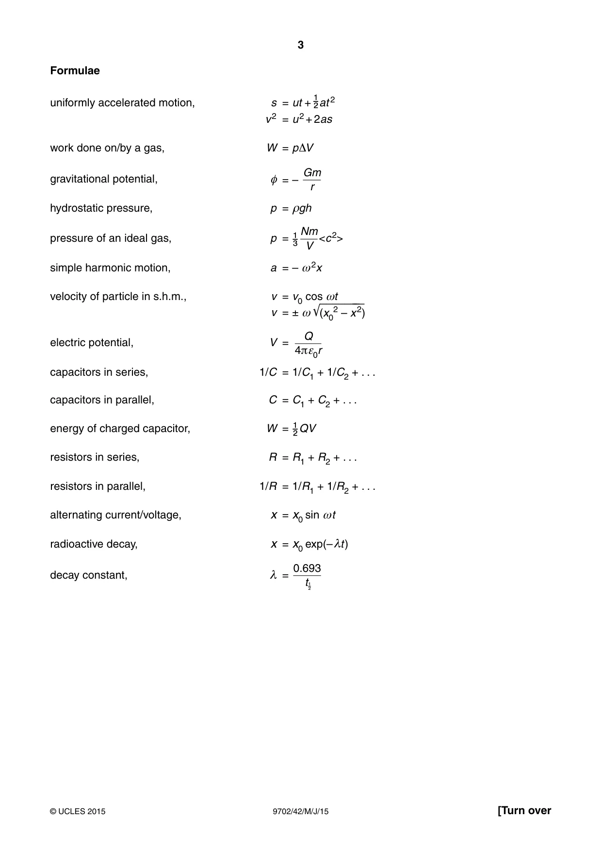
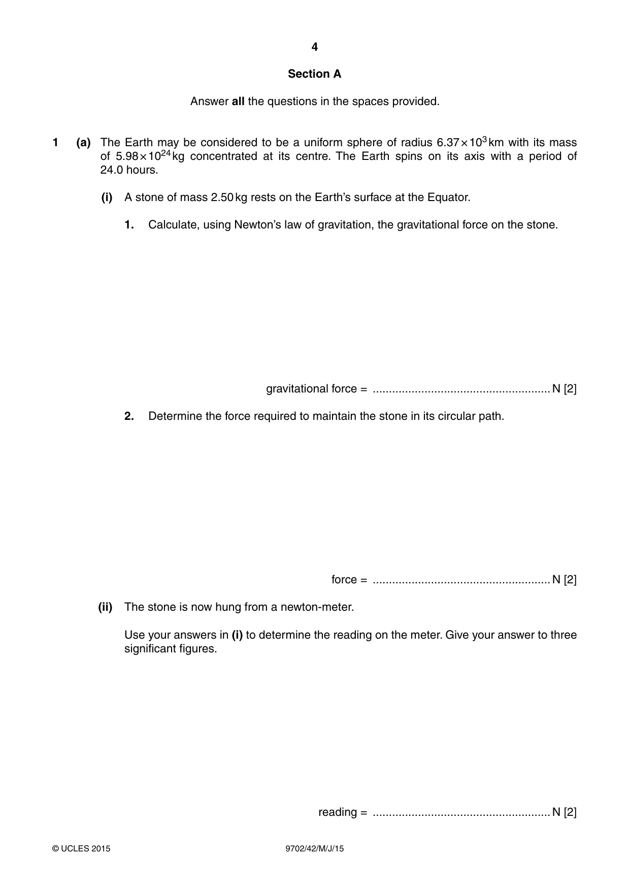




Mark scheme6 pages
Answers below. Sit the paper first if you are practising.

Questions as text
Q1 · The Earth may be considered to be a uniform sphere of radius 6.37 × 10³ km with its mass…
1 (a) The Earth may be considered to be a uniform sphere of radius 6.37 × 10³ km with its mass of 5.98 × 1024 kg concentrated at its centre. The Earth spins on its axis with a period of 24.0 hours. (i) A stone of mass 2.50 kg rests on the Earth’s surface at the Equator. 1. Calculate, using Newton’s law of gravitation, the gravitational force on the stone. gravitational force = .......................................................N [2] 2. Determine the force required to maintain the stone in its circular path. force = .......................................................N [2] (ii) The stone is now hung from a newton-meter. Use your answers in (i) to determine the reading on the meter. Give your answer to three significant figures. reading = .......................................................N [2] (b) A satellite is orbiting the Earth. For an astronaut in the satellite, his sensation of weight is caused by the contact force from his surroundings. The astronaut reports that he is ‘weightless’, despite being in the Earth’s gravitational field. Suggest what is meant by the astronaut reporting that he is ‘weightless’. ................................................................................................................................................... ................................................................................................................................................... ................................................................................................................................................... ...............................................................................................................................................[3]
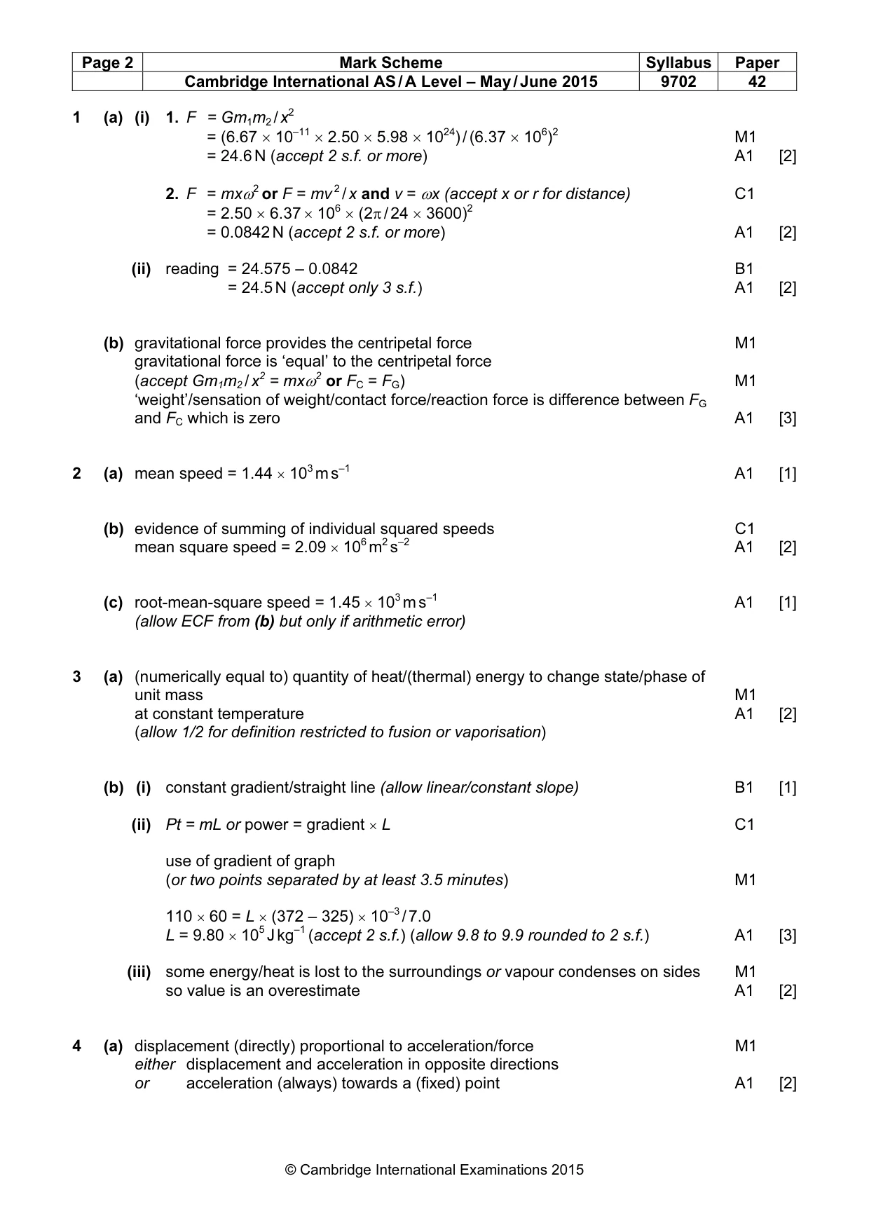
Mark scheme: 1 (a) (i) 1. F = Gm1m2 / x2 = (6.67 × 10–11 × 2.50 × 5.98 × 1024) / (6.37 × 10⁶)2 M1 = 24.6 N (accept 2 s.f. or more) A1 [2] 2. F = mxω2 or F = mv 2 / x and v = ωx (accept x or r for distance) C1 = 2.50 × 6.37 × 106 × (2π / 24 × 3600)2 = 0.0842 N (accept 2 s.f. or more) A1 [2] (ii) reading = 24.575 – 0.0842 B1 = 24.5 N (accept only 3 s.f.) A1 [2] (b) gravitational force provides the centripetal force M1 gravitational force is ‘equal’ to the centripetal force (accept Gm1m2 / x2 = mxω2 or FC = FG) M1 ‘weight’/sensation of weight/contact force/reaction force is difference between FG and FC which is zero A1 [3] 3 1
Q2 · In a sample of gas at room temperature, five atoms have the following speeds: 1.32 × 10³…
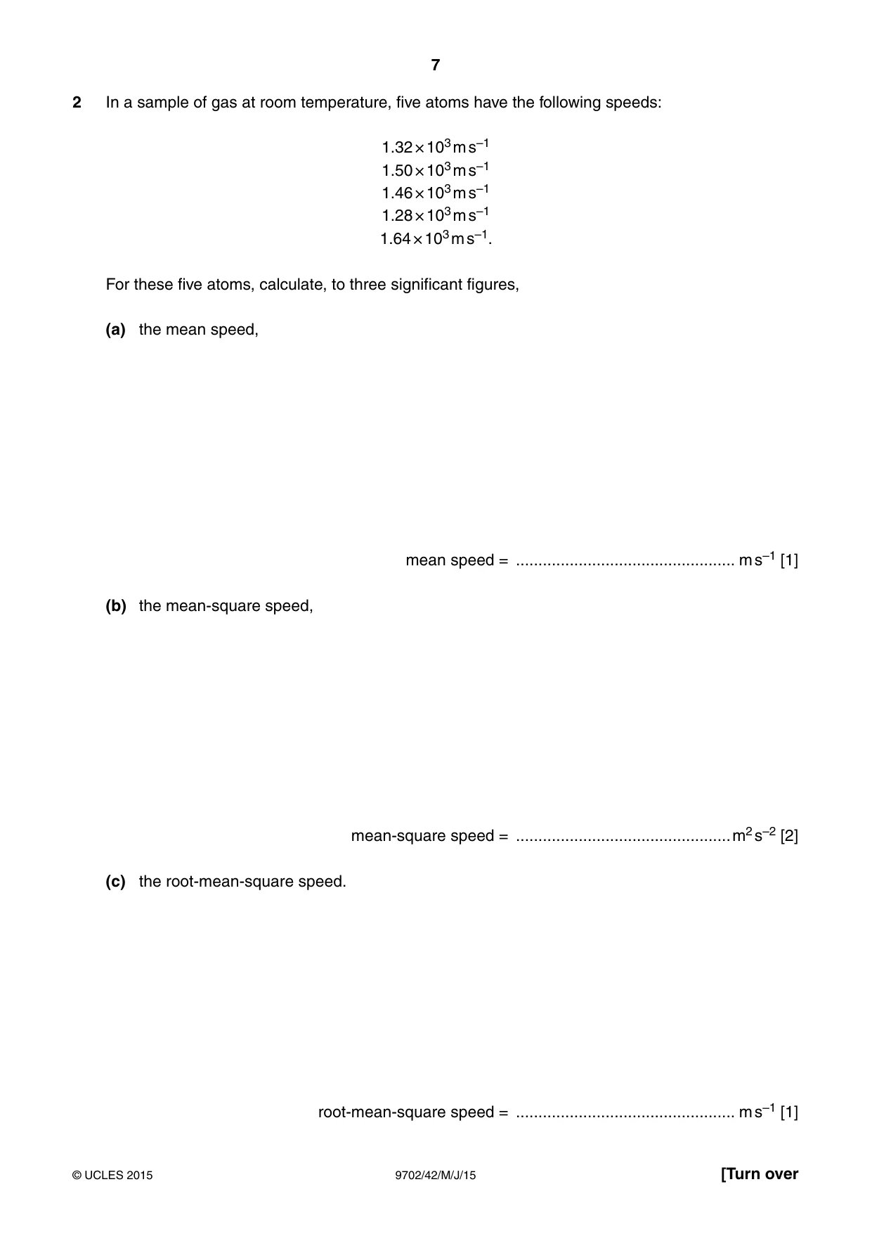
2 In a sample of gas at room temperature, five atoms have the following speeds: 1.32 × 10³ m s–1 1.50 × 10³ m s–1 1.46 × 10³ m s–1 1.28 × 10³ m s–1 1.64 × 10³ m s–1. For these five atoms, calculate, to three significant figures, (a) the mean speed, mean speed = ................................................. m s–1 [1] (b) the mean-square speed, mean-square speed = ................................................m2 s–2 [2] (c) the root-mean-square speed. root-mean-square speed = ................................................. m s–1 [1]
Mark scheme: 2 (a) mean speed = 1.44 × 10³ m s–1 A1 [1] (b) evidence of summing of individual squared speeds C1 mean square speed = 2.09 × 10⁶ m2 s–2 A1 [2] (c) root-mean-square speed = 1.45 × 10³ m s–1 A1 [1] (allow ECF from (b) but only if arithmetic error)
Q3 · Define specific latent heat
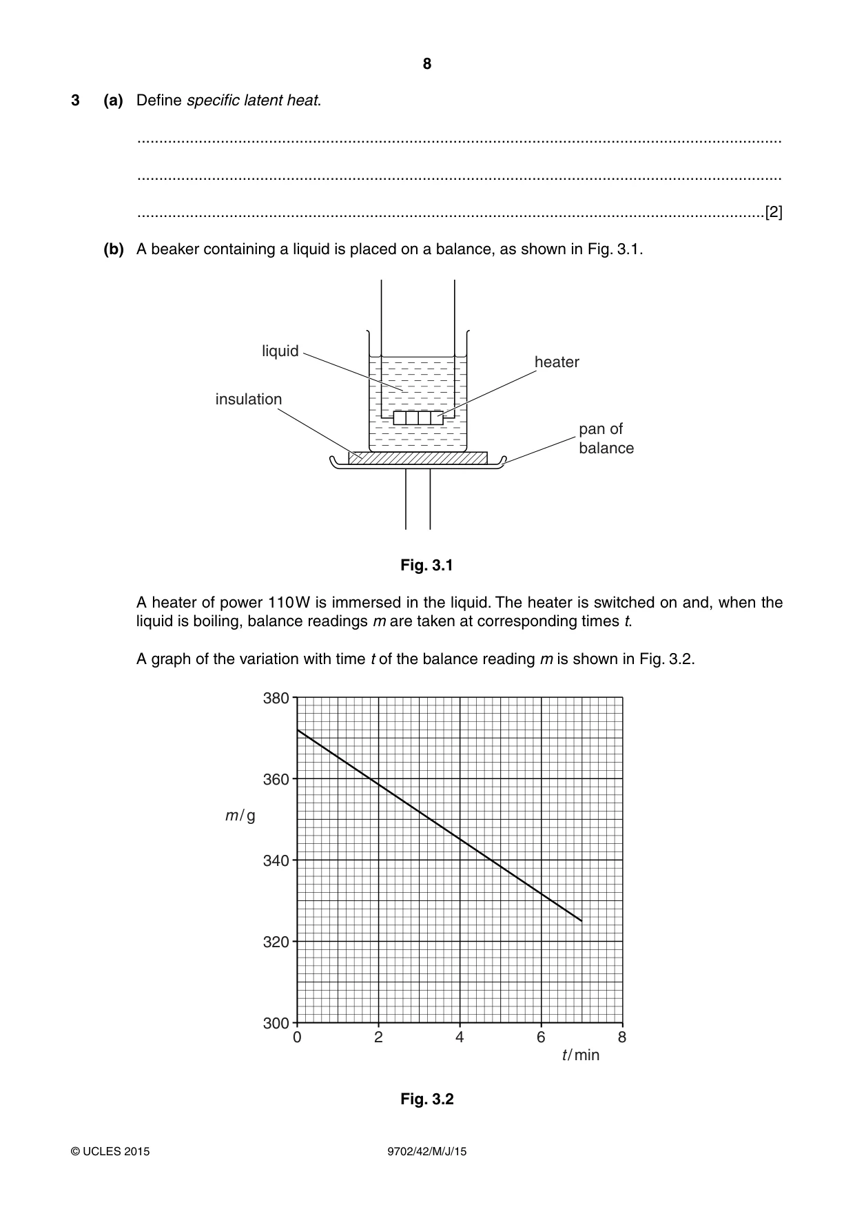
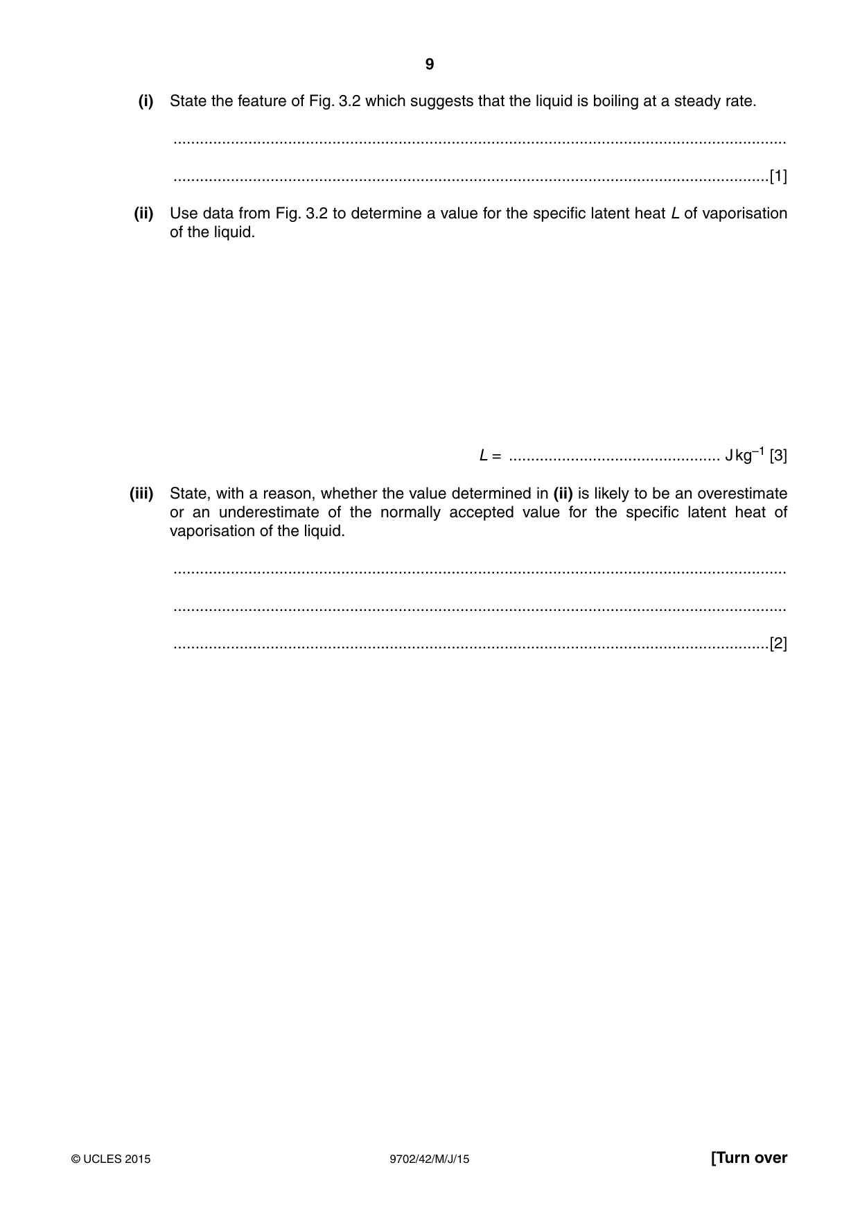
3 (a) Define specific latent heat. ................................................................................................................................................... ................................................................................................................................................... ...............................................................................................................................................[2] (b) A beaker containing a liquid is placed on a balance, as shown in Fig. 3.1. liquid heater insulation pan of balance Fig. 3.1 A heater of power 110 W is immersed in the liquid. The heater is switched on and, when the liquid is boiling, balance readings m are taken at corresponding times t. A graph of the variation with time t of the balance reading m is shown in Fig. 3.2. 380 360 m / g 340 320 300 0 2 4 6 8 t / min Fig. 3.2 (i) State the feature of Fig. 3.2 which suggests that the liquid is boiling at a steady rate. ........................................................................................................................................... .......................................................................................................................................[1] (ii) Use data from Fig. 3.2 to determine a value for the specific latent heat L of vaporisation of the liquid. L = ................................................ J kg–1 [3] (iii) State, with a reason, whether the value determined in (ii) is likely to be an overestimate or an underestimate of the normally accepted value for the specific latent heat of vaporisation of the liquid. ........................................................................................................................................... ........................................................................................................................................... .......................................................................................................................................[2]
Mark scheme: 3 (a) (numerically equal to) quantity of heat/(thermal) energy to change state/phase of unit mass M1 at constant temperature A1 [2] (allow 1/2 for definition restricted to fusion or vaporisation) (b) (i) constant gradient/straight line (allow linear/constant slope) B1 [1] (ii) Pt = mL or power = gradient × L C1 use of gradient of graph (or two points separated by at least 3.5 minutes) M1 110 × 60 = L × (372 – 325) × 10–3 / 7.0 L = 9.80 × 10⁵ J kg–1 (accept 2 s.f.) (allow 9.8 to 9.9 rounded to 2 s.f.) A1 [3] (iii) some energy/heat is lost to the surroundings or vapour condenses on sides M1 so value is an overestimate A1 [2]
More questions on Specific heat capacity and specific latent heat
Q4 · State what is meant by simple harmonic motion
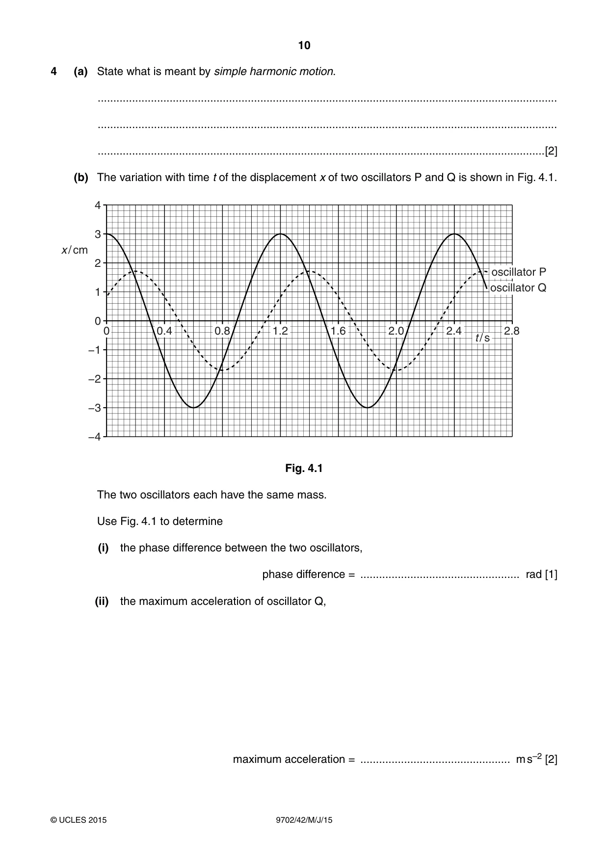
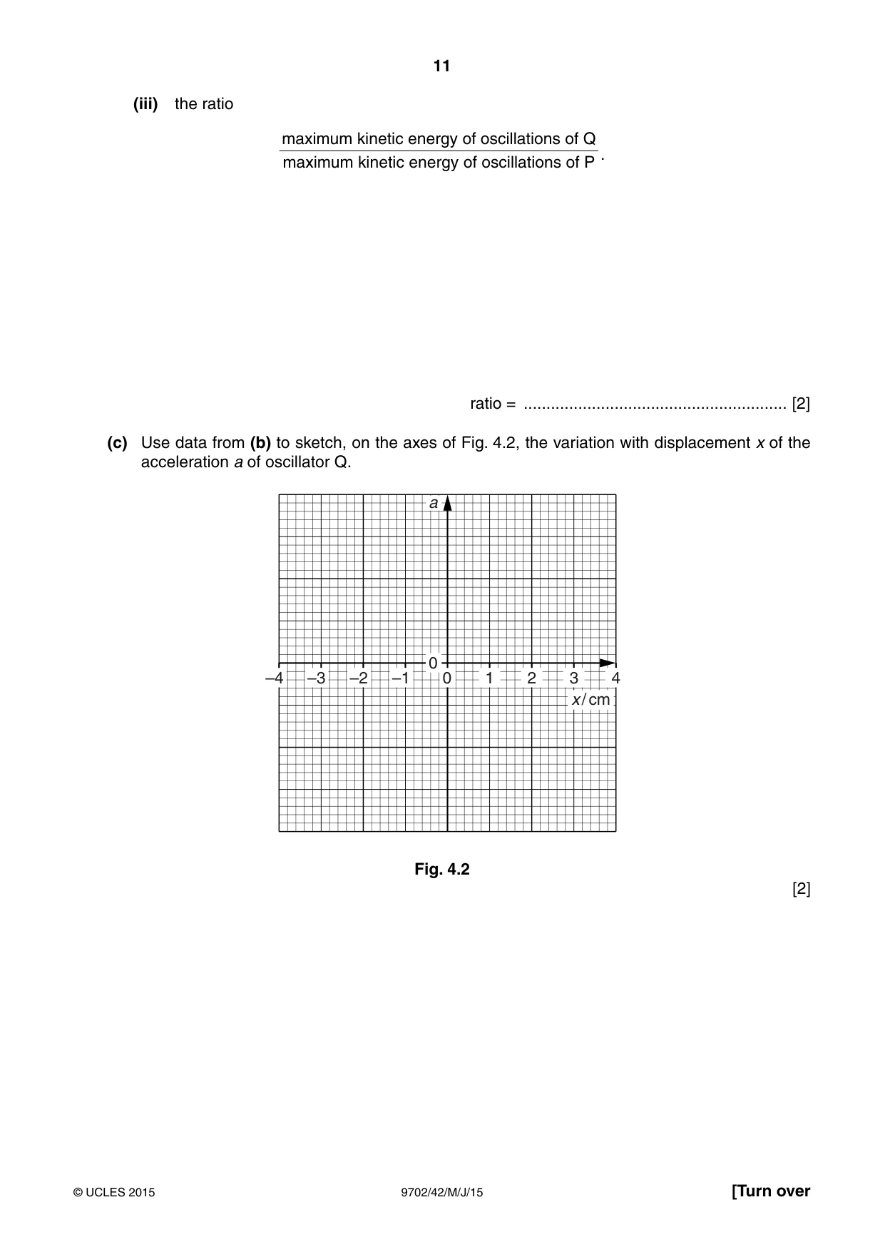
4 (a) State what is meant by simple harmonic motion. ................................................................................................................................................... ................................................................................................................................................... ...............................................................................................................................................[2] (b) The variation with time t of the displacement x of two oscillators P and Q is shown in Fig. 4.1. 4 3 x / cm 2 oscillator P oscillator Q 1 0 0 0.4 0.8 1.2 1.6 2.0 2.4 2.8 t / s −1 −2 −3 −4 Fig. 4.1 The two oscillators each have the same mass. Use Fig. 4.1 to determine (i) the phase difference between the two oscillators, phase difference = ................................................... rad [1] (ii) the maximum acceleration of oscillator Q, maximum acceleration = ................................................ m s–2 [2] (iii) the ratio maximum kinetic energy of oscillations of Q . maximum kinetic energy of oscillations of P ratio = .......................................................... [2] (c) Use data from (b) to sketch, on the axes of Fig. 4.2, the variation with displacement x of the acceleration a of oscillator Q. a 0 –4 –3 –2 –1 0 1 2 3 4 x / cm Fig. 4.2 [2]
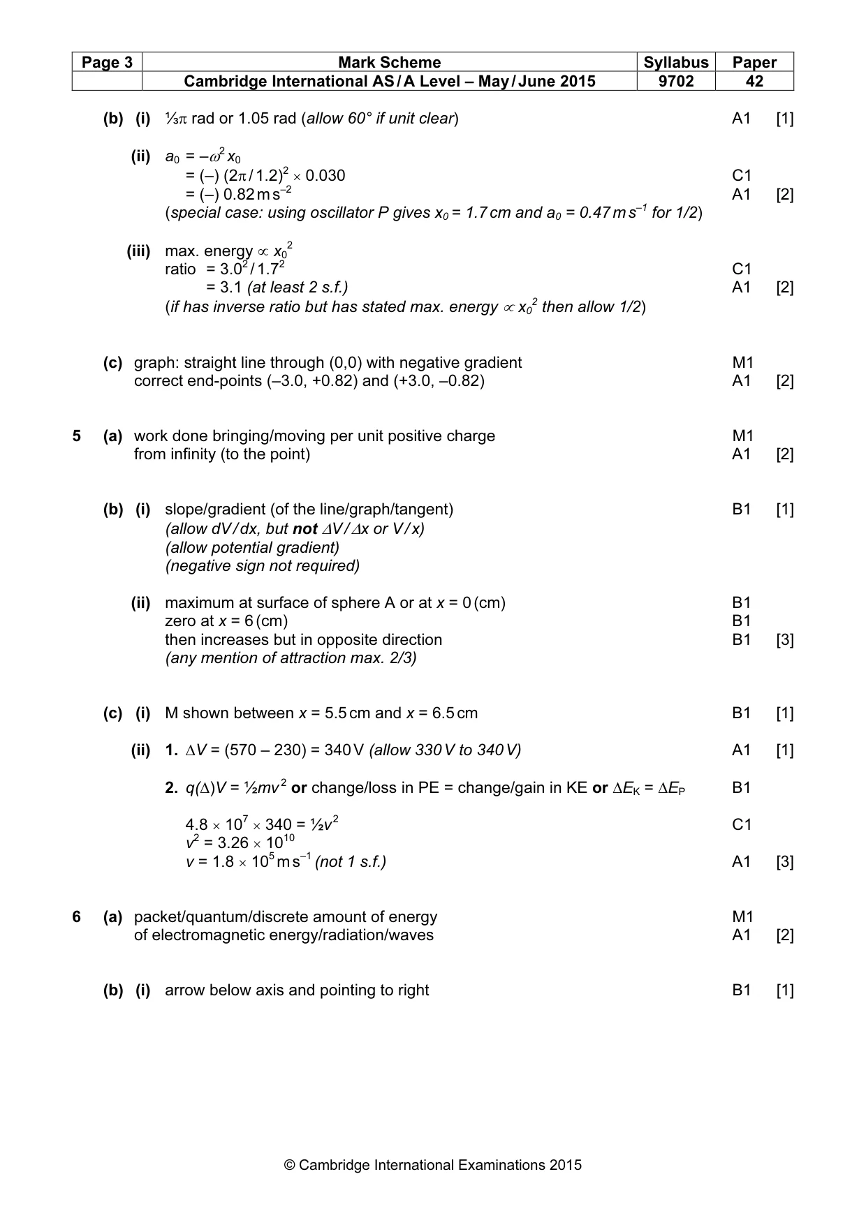
Mark scheme: 4 (a) displacement (directly) proportional to acceleration/force M1 either displacement and acceleration in opposite directions or acceleration (always) towards a (fixed) point A1 [2] (b) (i) ⅓π rad or 1.05 rad (allow 60° if unit clear) A1 [1] (ii) a0 = –ω2 x0 = (–) (2π / 1.2)2 × 0.030 C1 = (–) 0.82 m s–2 A1 [2] (special case: using oscillator P gives x0 = 1.7 cm and a0 = 0.47 m s–1 for 1/2) (iii) max. energy ∝ x02 ratio = 3.02 / 1.72 C1 = 3.1 (at least 2 s.f.) A1 [2] (if has inverse ratio but has stated max. energy ∝ x02 then allow 1/2) (c) graph: straight line through (0,0) with negative gradient M1 correct end-points (–3.0, +0.82) and (+3.0, –0.82) A1 [2]
Q5 · Define electric potential at a point
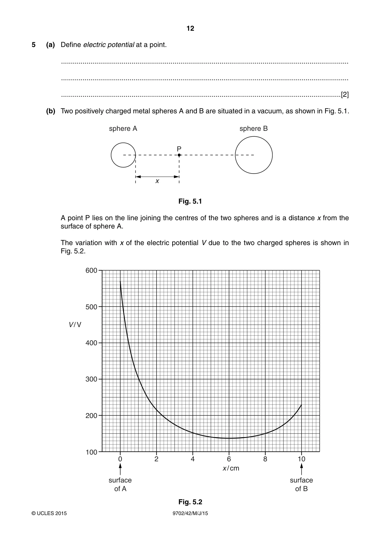
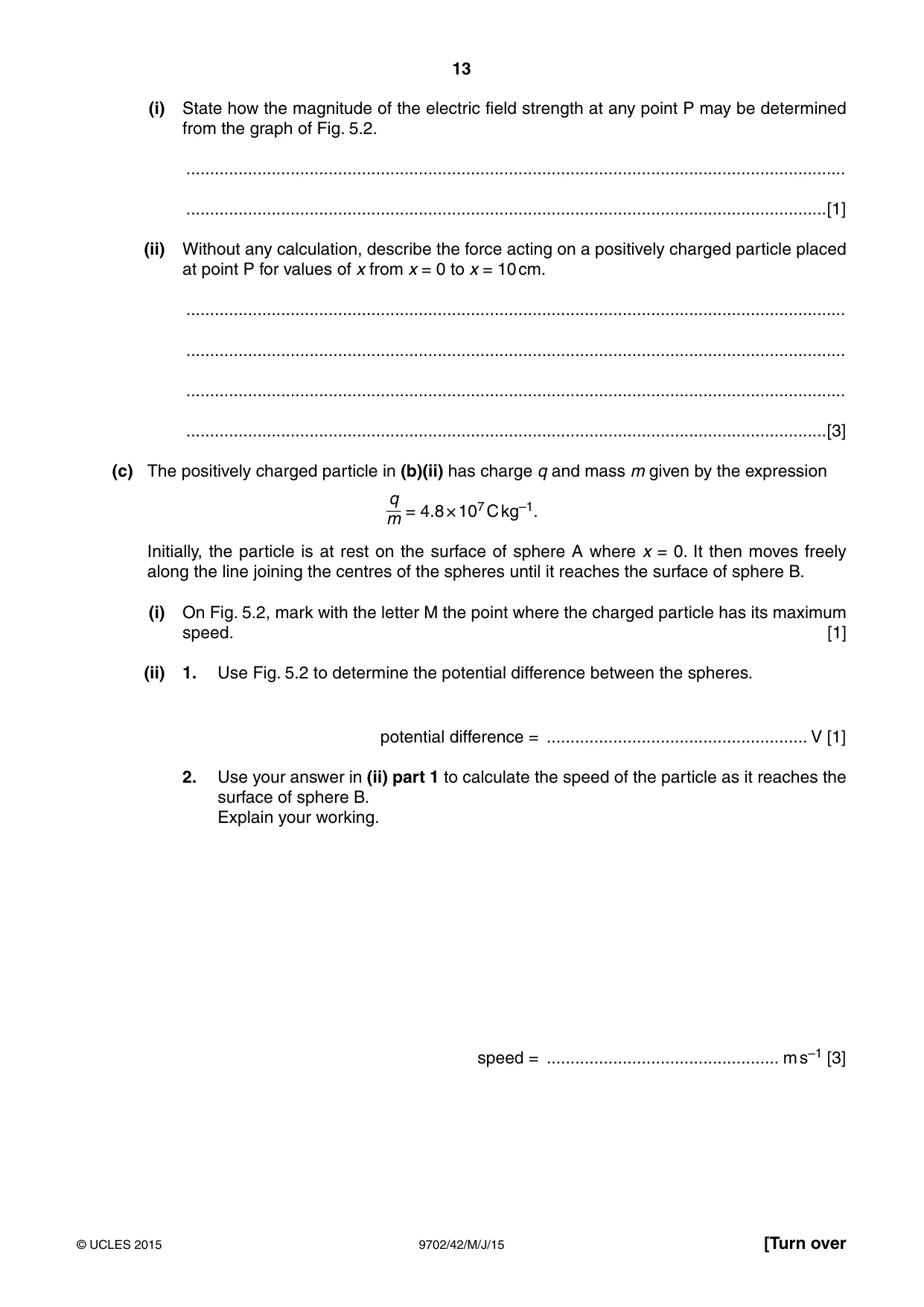
5 (a) Define electric potential at a point. ................................................................................................................................................... ................................................................................................................................................... ...............................................................................................................................................[2] (b) Two positively charged metal spheres A and B are situated in a vacuum, as shown in Fig. 5.1. sphere A sphere B P x Fig. 5.1 A point P lies on the line joining the centres of the two spheres and is a distance x from the surface of sphere A. The variation with x of the electric potential V due to the two charged spheres is shown in Fig. 5.2. 600 500 V / V 400 300 200 100 0 2 4 6 8 10 x / cm surface surface of A of B Fig. 5.2 (i) State how the magnitude of the electric field strength at any point P may be determined from the graph of Fig. 5.2. ........................................................................................................................................... .......................................................................................................................................[1] (ii) Without any calculation, describe the force acting on a positively charged particle placed at point P for values of x from x = 0 to x = 10 cm. ........................................................................................................................................... ........................................................................................................................................... ........................................................................................................................................... .......................................................................................................................................[3] (c) The positively charged particle in (b)(ii) has charge q and mass m given by the expression q = 4.8 × 10⁷ C kg–1. m Initially, the particle is at rest on the surface of sphere A where x = 0. It then moves freely along the line joining the centres of the spheres until it reaches the surface of sphere B. (i) On Fig. 5.2, mark with the letter M the point where the charged particle has its maximum speed. [1] (ii) 1. Use Fig. 5.2 to determine the potential difference between the spheres. potential difference = ....................................................... V [1] 2. Use your answer in (ii) part 1 to calculate the speed of the particle as it reaches the surface of sphere B. Explain your working. speed = ................................................. m s–1 [3]
Mark scheme: 5 (a) work done bringing/moving per unit positive charge M1 from infinity (to the point) A1 [2] (b) (i) slope/gradient (of the line/graph/tangent) B1 [1] (allow dV / dx, but not ∆V / ∆x or V / x) (allow potential gradient) (negative sign not required) (ii) maximum at surface of sphere A or at x = 0 (cm) B1 zero at x = 6 (cm) B1 then increases but in opposite direction B1 [3] (any mention of attraction max. 2/3) (c) (i) M shown between x = 5.5 cm and x = 6.5 cm B1 [1] (ii) 1. ∆V = (570 – 230) = 340 V (allow 330 V to 340 V) A1 [1] 2. q(∆)V = ½mv 2 or change/loss in PE = change/gain in KE or ∆EK = ∆EP B1 4.8 × 107 × 340 = ½v 2 C1 v2 = 3.26 × 10¹⁰ v = 1.8 × 10⁵ m s–1 (not 1 s.f.) A1 [3]
Q6 · Explain what is meant by a photon
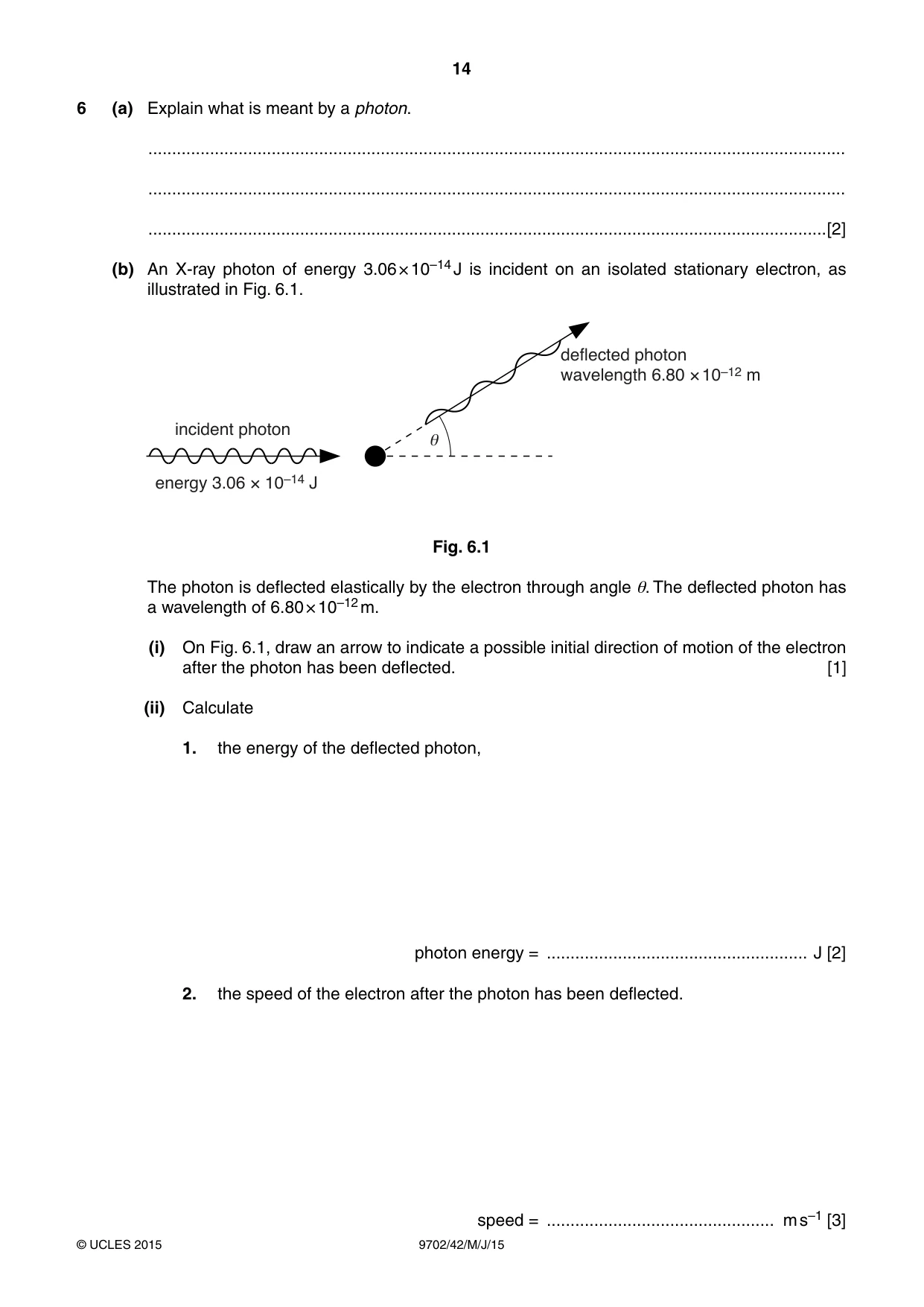
6 (a) Explain what is meant by a photon. ................................................................................................................................................... ................................................................................................................................................... ...............................................................................................................................................[2] (b) An X-ray photon of energy 3.06 × 10⁻¹⁴ J is incident on an isolated stationary electron, as illustrated in Fig. 6.1. deflected photon wavelength 6.80 × 10⁻¹² m incident photon e energy 3.06 × 10⁻¹⁴ J Fig. 6.1 The photon is deflected elastically by the electron through angle θ. The deflected photon has a wavelength of 6.80 × 10⁻¹² m. (i) On Fig. 6.1, draw an arrow to indicate a possible initial direction of motion of the electron after the photon has been deflected. [1] (ii) Calculate 1. the energy of the deflected photon, photon energy = ....................................................... J [2] 2. the speed of the electron after the photon has been deflected. speed = ................................................ m s–1 [3] (c) Explain why the magnitude of the final momentum of the electron is not equal to the change in magnitude of the momentum of the photon. ................................................................................................................................................... ................................................................................................................................................... .............................................................................................................................................. [2]
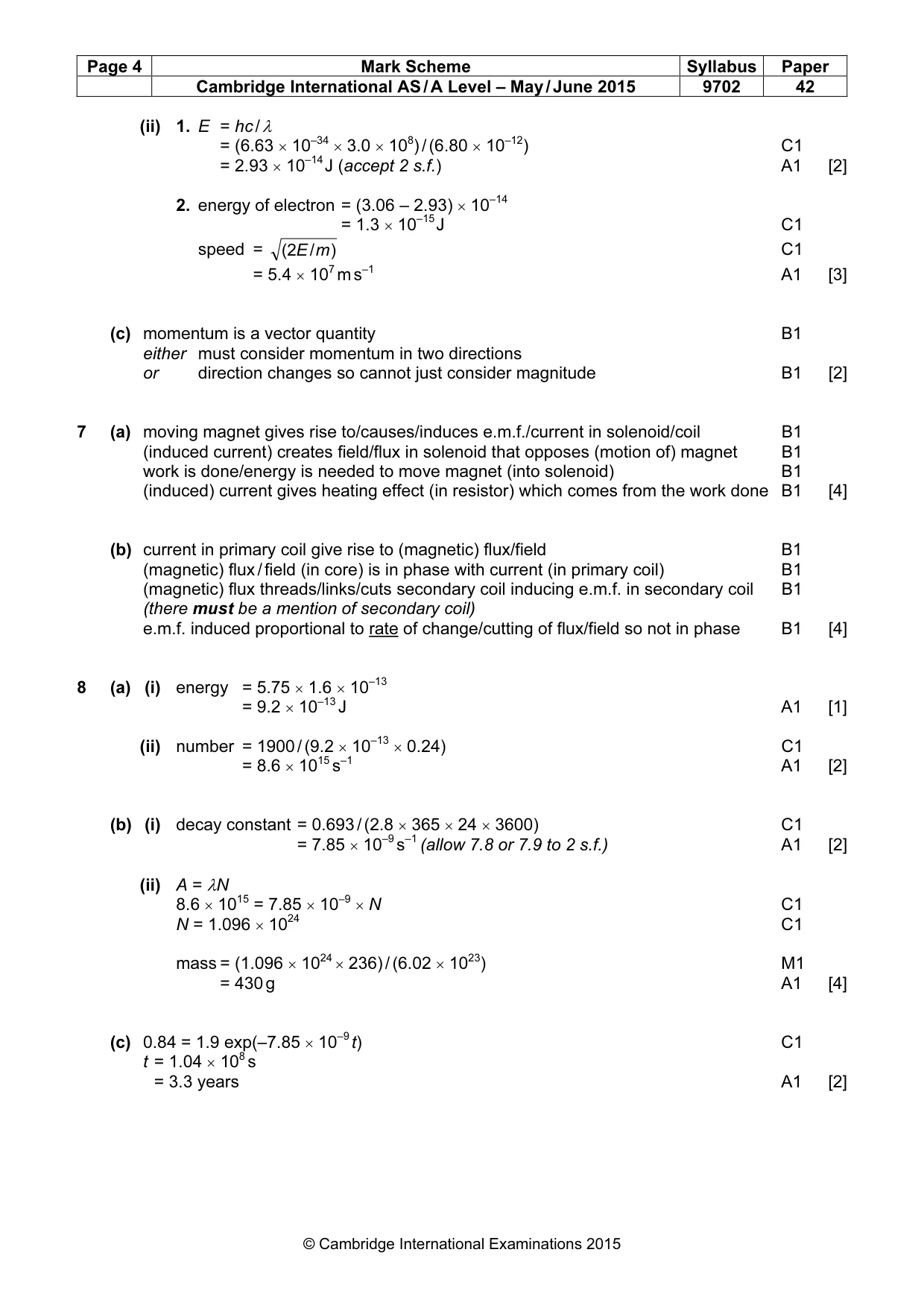
Mark scheme: 6 (a) packet/quantum/discrete amount of energy M1 of electromagnetic energy/radiation/waves A1 [2] (b) (i) arrow below axis and pointing to right B1 [1] (ii) 1. E = hc / λ = (6.63 × 10–34 × 3.0 × 108) / (6.80 × 10⁻¹²) C1 = 2.93 × 10⁻¹⁴ J (accept 2 s.f.) A1 [2] 2. energy of electron = (3.06 – 2.93) × 10–14 = 1.3 × 10⁻¹⁵ J C1 speed = (2E / m ) C1 = 5.4 × 10⁷ m s–1 A1 [3] (c) momentum is a vector quantity B1 either must consider momentum in two directions or direction changes so cannot just consider magnitude B1 [2]
Q7 · A solenoid is connected in series with a resistor, as shown in Fig
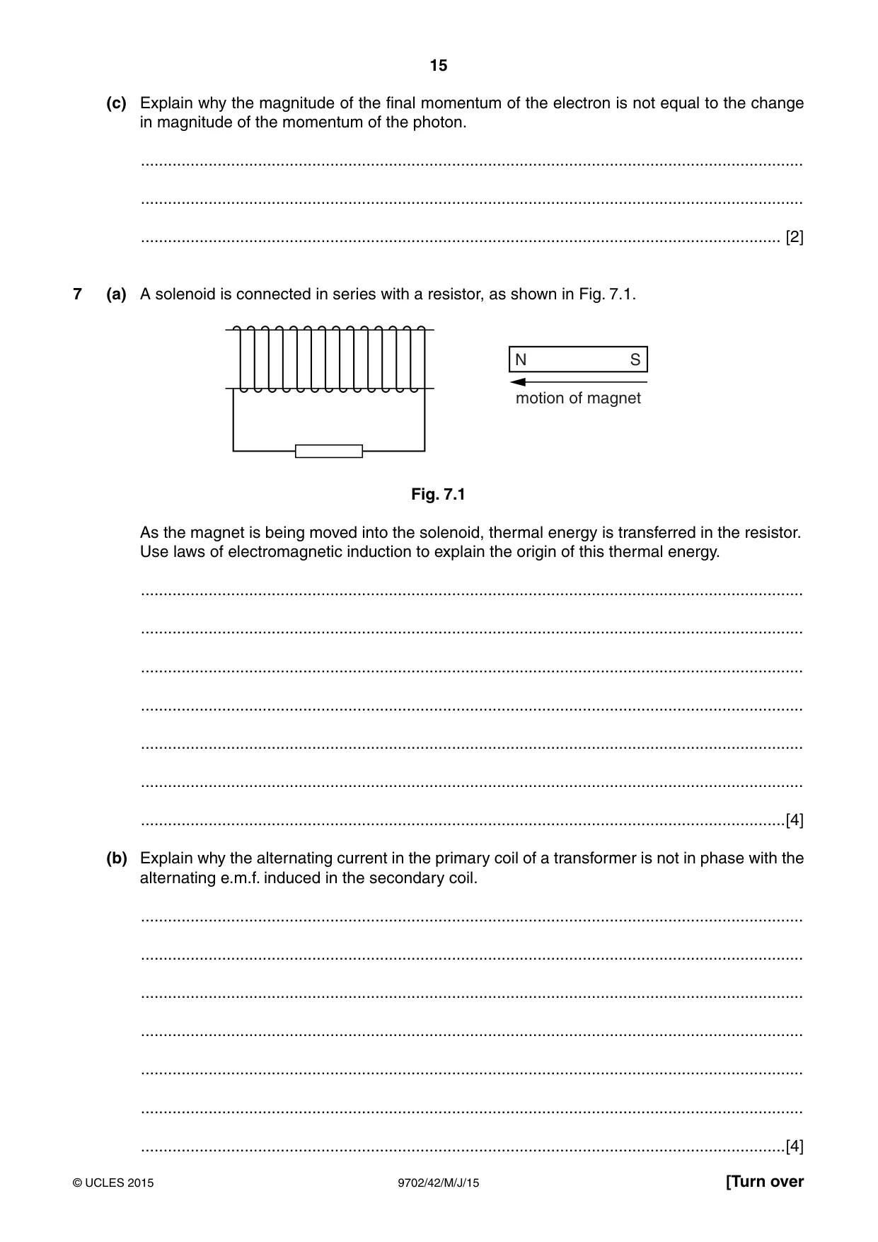
7 (a) A solenoid is connected in series with a resistor, as shown in Fig. 7.1. N S motion of magnet Fig. 7.1 As the magnet is being moved into the solenoid, thermal energy is transferred in the resistor. Use laws of electromagnetic induction to explain the origin of this thermal energy. ................................................................................................................................................... ................................................................................................................................................... ................................................................................................................................................... ................................................................................................................................................... ................................................................................................................................................... ................................................................................................................................................... ...............................................................................................................................................[4] (b) Explain why the alternating current in the primary coil of a transformer is not in phase with the alternating e.m.f. induced in the secondary coil. ................................................................................................................................................... ................................................................................................................................................... ................................................................................................................................................... ................................................................................................................................................... ................................................................................................................................................... ................................................................................................................................................... ...............................................................................................................................................[4]
Mark scheme: 7 (a) moving magnet gives rise to/causes/induces e.m.f./current in solenoid/coil B1 (induced current) creates field/flux in solenoid that opposes (motion of) magnet B1 work is done/energy is needed to move magnet (into solenoid) B1 (induced) current gives heating effect (in resistor) which comes from the work done B1 [4] (b) current in primary coil give rise to (magnetic) flux/field B1 (magnetic) flux / field (in core) is in phase with current (in primary coil) B1 (magnetic) flux threads/links/cuts secondary coil inducing e.m.f. in secondary coil B1 (there must be a mention of secondary coil) e.m.f. induced proportional to rate of change/cutting of flux/field so not in phase B1 [4] 13
Q8 · The power for a space probe is to be supplied by the energy released when plutonium-236…
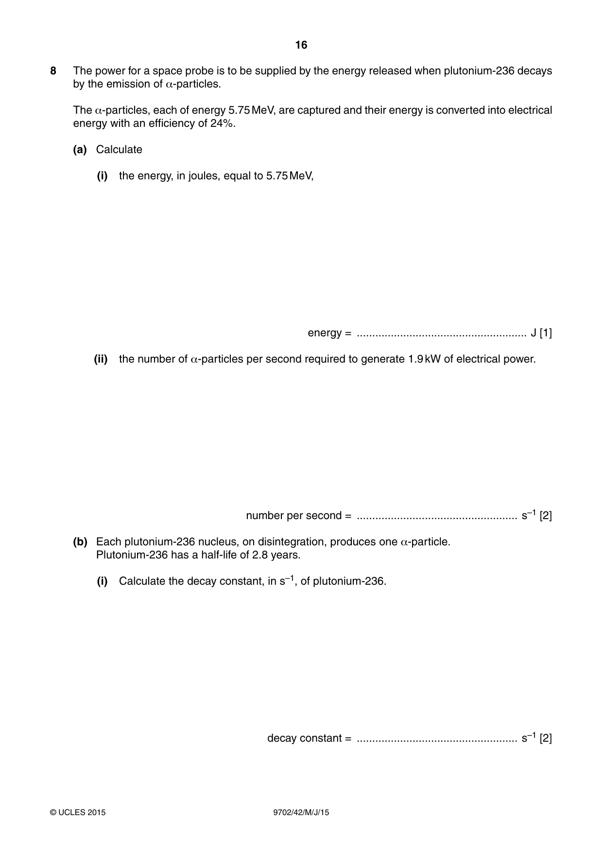
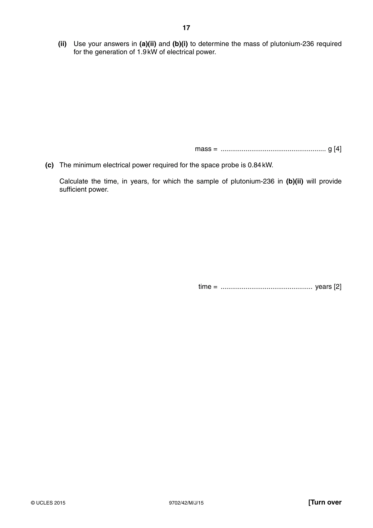
8 The power for a space probe is to be supplied by the energy released when plutonium-236 decays by the emission of α-particles. The α-particles, each of energy 5.75 MeV, are captured and their energy is converted into electrical energy with an efficiency of 24%. (a) Calculate (i) the energy, in joules, equal to 5.75 MeV, energy = ....................................................... J [1] (ii) the number of α-particles per second required to generate 1.9 kW of electrical power. number per second = .................................................... s–1 [2] (b) Each plutonium-236 nucleus, on disintegration, produces one α-particle. Plutonium-236 has a half-life of 2.8 years. (i) Calculate the decay constant, in s–1, of plutonium-236. decay constant = .................................................... s–1 [2] (ii) Use your answers in (a)(ii) and (b)(i) to determine the mass of plutonium-236 required for the generation of 1.9 kW of electrical power. mass = ....................................................... g [4] (c) The minimum electrical power required for the space probe is 0.84 kW. Calculate the time, in years, for which the sample of plutonium-236 in (b)(ii) will provide sufficient power. time = ................................................ years [2]
Mark scheme: 8 (a) (i) energy = 5.75 × 1.6 × 10–13 = 9.2 × 10⁻¹³ J A1 [1] (ii) number = 1900 / (9.2 × 10–13 × 0.24) C1 = 8.6 × 10¹⁵ s–1 A1 [2] (b) (i) decay constant = 0.693 / (2.8 × 365 × 24 × 3600) C1 = 7.85 × 10⁻⁹ s–1 (allow 7.8 or 7.9 to 2 s.f.) A1 [2] (ii) A = λN 8.6 × 1015 = 7.85 × 10⁻⁹ × N C1 N = 1.096 × 1024 C1 mass = (1.096 × 1024 × 236) / (6.02 × 10²³) M1 = 430 g A1 [4] (c) 0.84 = 1.9 exp(–7.85 × 10⁻⁹ t) C1 t = 1.04 × 10⁸ s = 3.3 years A1 [2] Section B
Q9 · The strain in a beam is to be monitored using a strain gauge
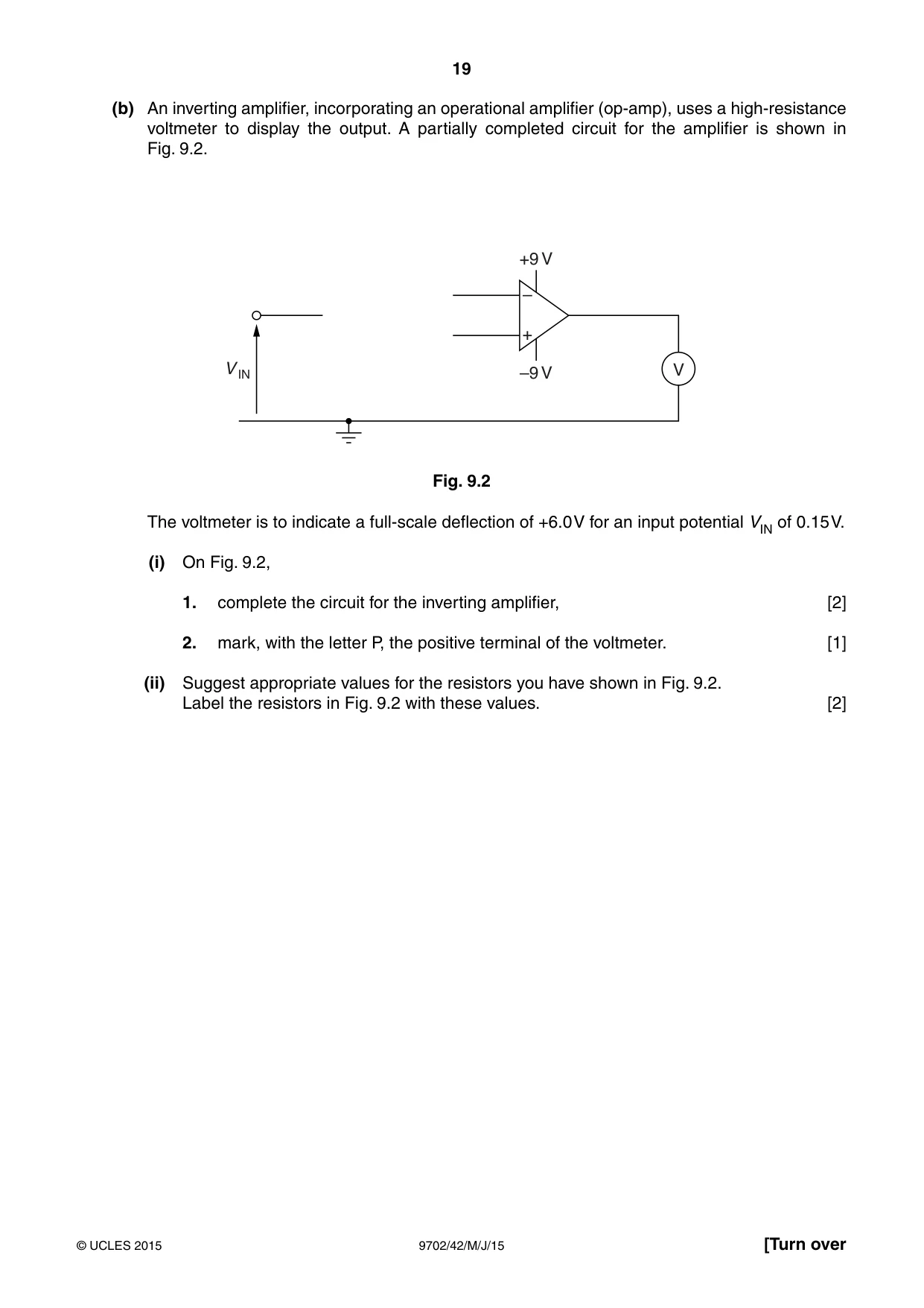
9 (a) The strain in a beam is to be monitored using a strain gauge. The strain gauge is included in the potential divider circuit shown in Fig. 9.1. +2000 mV 120.0 1 5000 1 A B strain 5000 1 gauge Fig. 9.1 The strain gauge has a resistance of 120.0 Ω when it is not strained. The resistance increases to 121.5 Ω when the strain is ε. Calculate the potential difference between points A and B on Fig. 9.1 when the strain in the gauge is ε. potential difference = ................................................... mV [3] (b) An inverting amplifier, incorporating an operational amplifier (op-amp), uses a high-resistance voltmeter to display the output. A partially completed circuit for the amplifier is shown in Fig. 9.2. +9 V – + V IN –9 V V Fig. 9.2 The voltmeter is to indicate a full-scale deflection of +6.0 V for an input potential VIN of 0.15 V. (i) On Fig. 9.2, 1. complete the circuit for the inverting amplifier, [2] 2. mark, with the letter P, the positive terminal of the voltmeter. [1] (ii) Suggest appropriate values for the resistors you have shown in Fig. 9.2. Label the resistors in Fig. 9.2 with these values. [2]
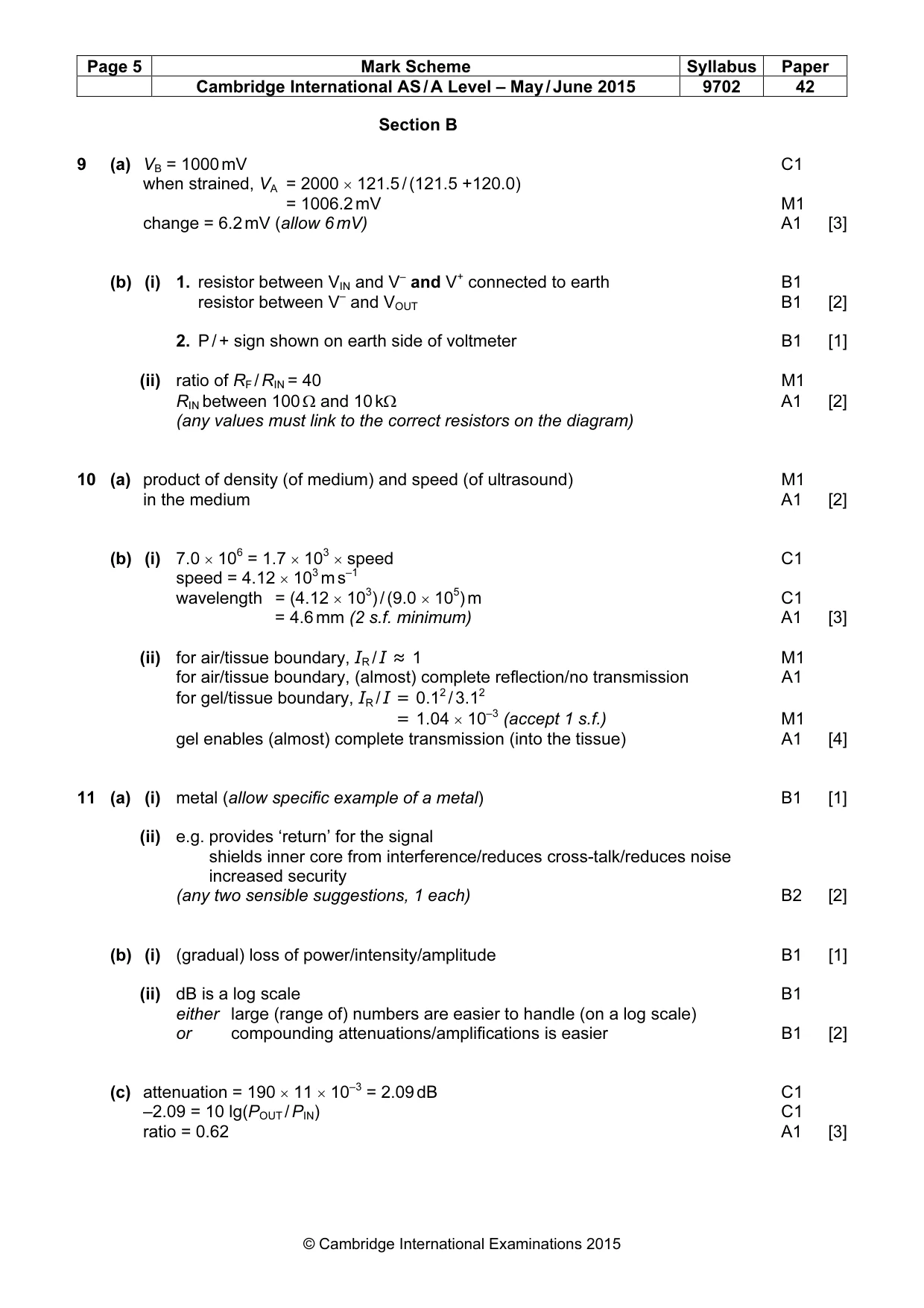
Mark scheme: 9 (a) VB = 1000 mV C1 when strained, VA = 2000 × 121.5 / (121.5 +120.0) = 1006.2 mV M1 change = 6.2 mV (allow 6 mV) A1 [3] (b) (i) 1. resistor between VIN and V– and V+ connected to earth B1 resistor between V– and VOUT B1 [2] 2. P / + sign shown on earth side of voltmeter B1 [1] (ii) ratio of RF / RIN = 40 M1 RIN between 100 Ω and 10 kΩ A1 [2] (any values must link to the correct resistors on the diagram)
Q10 · State what is meant by the specific acoustic impedance of a medium
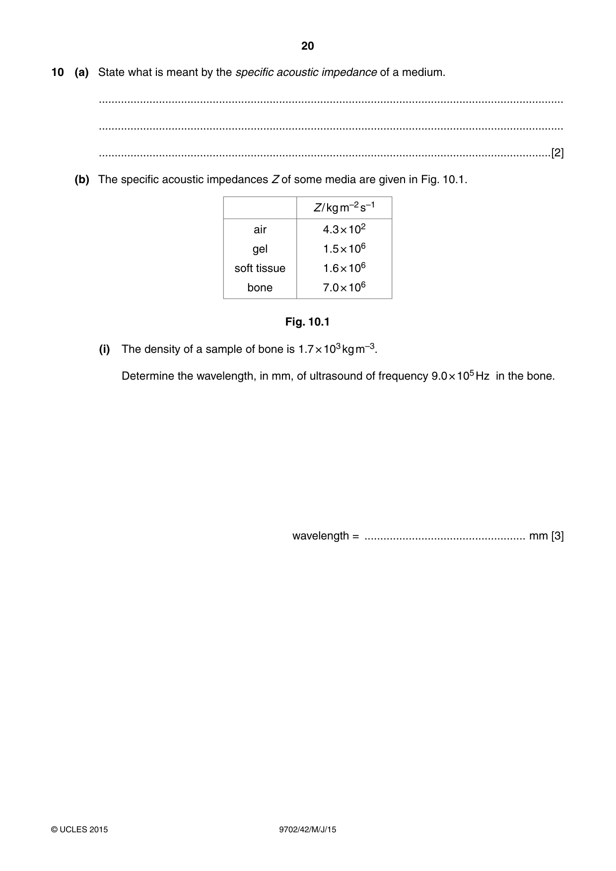
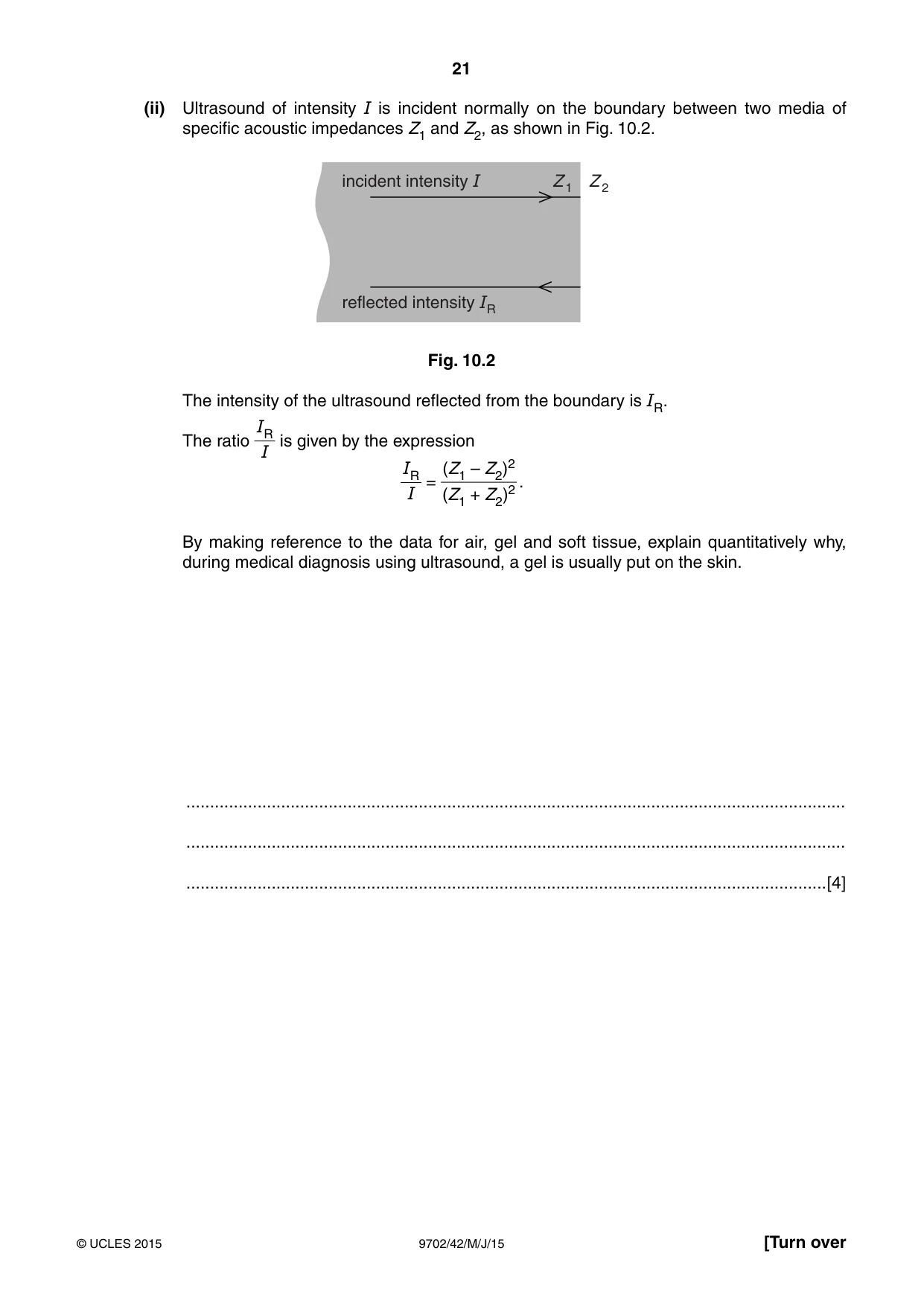
10 (a) State what is meant by the specific acoustic impedance of a medium. ................................................................................................................................................... ................................................................................................................................................... ...............................................................................................................................................[2] (b) The specific acoustic impedances Z of some media are given in Fig. 10.1. Z / kg m–2 s–1 air 4.3 × 10² gel 1.5 × 10⁶ soft tissue 1.6 × 10⁶ bone 7.0 × 10⁶ Fig. 10.1 (i) The density of a sample of bone is 1.7 × 10³ kg m–3. Determine the wavelength, in mm, of ultrasound of frequency 9.0 × 10⁵ Hz in the bone. wavelength = ................................................... mm [3] (ii) Ultrasound of intensity I is incident normally on the boundary between two media of specific acoustic impedances Z1 and Z2, as shown in Fig. 10.2. incident intensity I Z 1 Z 2 reflected intensity IR Fig. 10.2 The intensity of the ultrasound reflected from the boundary is IR. IR The ratio is given by the expression I IR (Z1 – Z2)2 = . I + (Z1 Z2)2 By making reference to the data for air, gel and soft tissue, explain quantitatively why, during medical diagnosis using ultrasound, a gel is usually put on the skin. ........................................................................................................................................... ........................................................................................................................................... .......................................................................................................................................[4]
Mark scheme: 10 (a) product of density (of medium) and speed (of ultrasound) M1 in the medium A1 [2] (b) (i) 7.0 × 106 = 1.7 × 10³ × speed C1 speed = 4.12 × 10³ m s–1 wavelength = (4.12 × 10³) / (9.0 × 10⁵) m C1 = 4.6 mm (2 s.f. minimum) A1 [3] (ii) for air/tissue boundary, IR / I ≈ 1 M1 for air/tissue boundary, (almost) complete reflection/no transmission A1 for gel/tissue boundary, IR / I = 0.12 / 3.12 = 1.04 × 10⁻³ (accept 1 s.f.) M1 gel enables (almost) complete transmission (into the tissue) A1 [4]
Q11 · One channel of communication is by the use of a coaxial cable
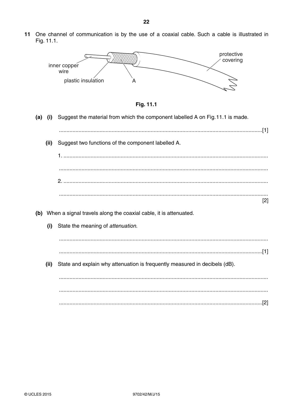
11 One channel of communication is by the use of a coaxial cable. Such a cable is illustrated in Fig. 11.1. protective covering inner copper wire plastic insulation A Fig. 11.1 (a) (i) Suggest the material from which the component labelled A on Fig. 11.1 is made. .......................................................................................................................................[1] (ii) Suggest two functions of the component labelled A. 1. ........................................................................................................................................ ........................................................................................................................................... 2. ........................................................................................................................................ ........................................................................................................................................... [2] (b) When a signal travels along the coaxial cable, it is attenuated. (i) State the meaning of attenuation. ........................................................................................................................................... .......................................................................................................................................[1] (ii) State and explain why attenuation is frequently measured in decibels (dB). ........................................................................................................................................... ........................................................................................................................................... .......................................................................................................................................[2] (c) A television aerial is connected to a receiver using a coaxial cable of length 11 m. The attenuation per unit length of the cable is 190 dB km–1. Calculate the ratio output signal from coaxial cable . input signal to coaxial cable ratio = ...........................................................[3] Please turn over for Question 12.
Mark scheme: 11 (a) (i) metal (allow specific example of a metal) B1 [1] (ii) e.g. provides ‘return’ for the signal shields inner core from interference/reduces cross-talk/reduces noise increased security (any two sensible suggestions, 1 each) B2 [2] (b) (i) (gradual) loss of power/intensity/amplitude B1 [1] (ii) dB is a log scale B1 either large (range of) numbers are easier to handle (on a log scale) or compounding attenuations/amplifications is easier B1 [2] (c) attenuation = 190 × 11 × 10–3 = 2.09 dB C1 –2.09 = 10 lg(POUT / PIN) C1 ratio = 0.62 A1 [3]
Q12 · A mobile phone handset is, at its simplest, a radio transmitter and receiver
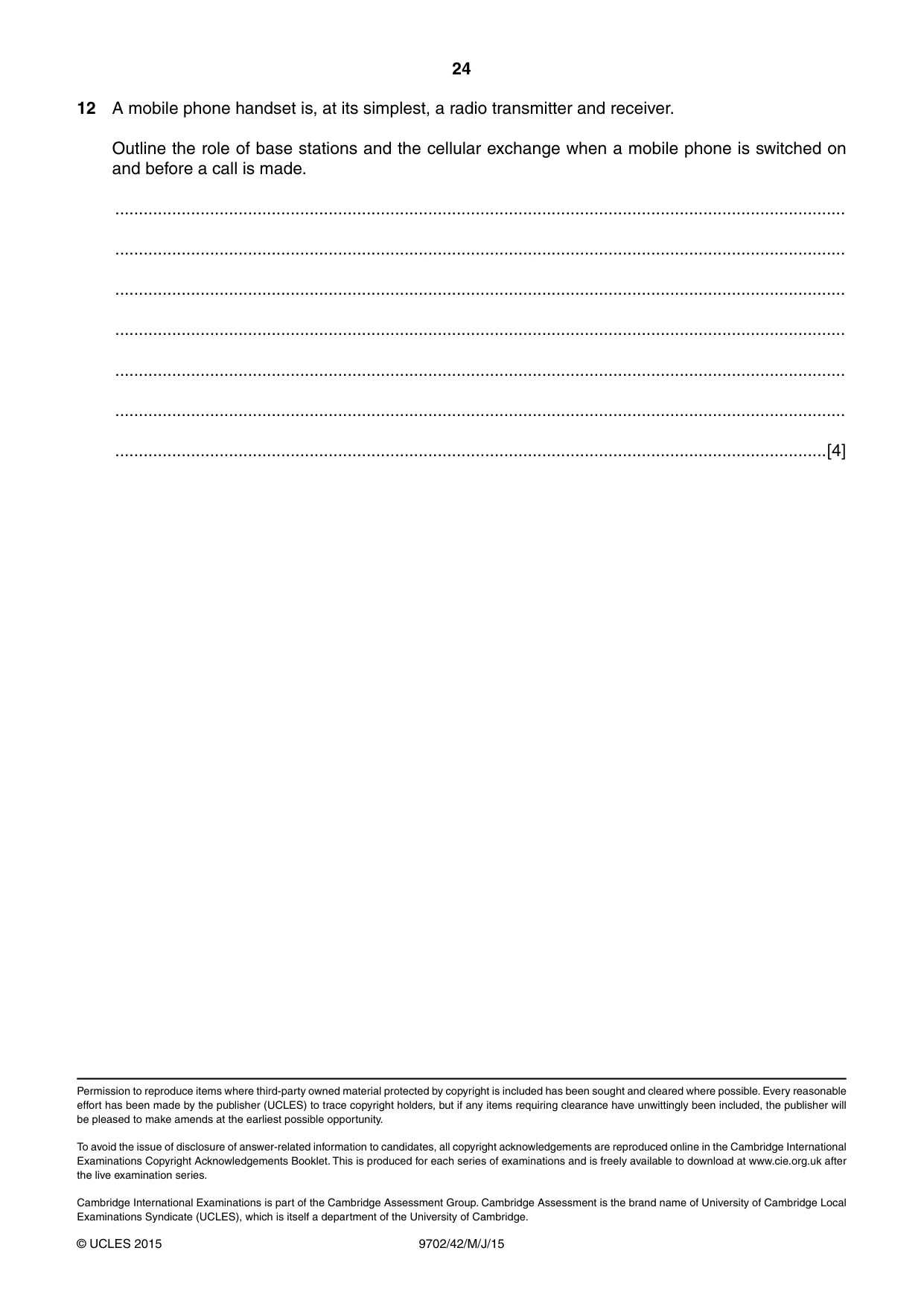
12 A mobile phone handset is, at its simplest, a radio transmitter and receiver. Outline the role of base stations and the cellular exchange when a mobile phone is switched on and before a call is made. .......................................................................................................................................................... .......................................................................................................................................................... .......................................................................................................................................................... .......................................................................................................................................................... .......................................................................................................................................................... .......................................................................................................................................................... ......................................................................................................................................................[4]
Mark scheme: 12 handset transmits (identification) signal to number of base stations B1 base stations transfers (signal) to cellular exchange B1 (idea of stations needed at least once in first two marking points) computer at cellular exchange selects base station with strongest signal B1 computer at cellular exchange selects a carrier frequency for mobile phone B1 [4] (idea of computer needed at least once in these two marking points)
What was in this paper
The subtopics covered by these 12 questions, and how many questions each got. Open one in a new tab to see every Cambridge question on it.
2Electromagnetic induction1Electromagnetic spectrum1Energy and momentum of a photon1Gravitational force between point masses1Kinetic theory of gases1Physical quantities1Potential dividers1Production and use of ultrasound1Simple harmonic oscillations1Specific heat capacity and specific latent heat1What you needed in this session
Cambridge’s own grade thresholds for 2015 May/June, Paper 4 · Variant 2. A higher threshold means an easier paper — the bar moves with how the cohort did.