Cambridge A Level Physics 9702 — 2011 May/June Paper 4 · Variant 1
9702/41/M/J/11 · 12 questions · 100 marks · ≈113 min
The question paper and its mark scheme, free to read here and free to download. This is Cambridge’s own paper, exactly as it was sat.
Question paper24 pages
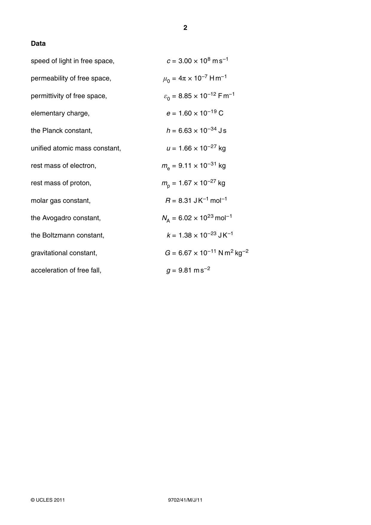
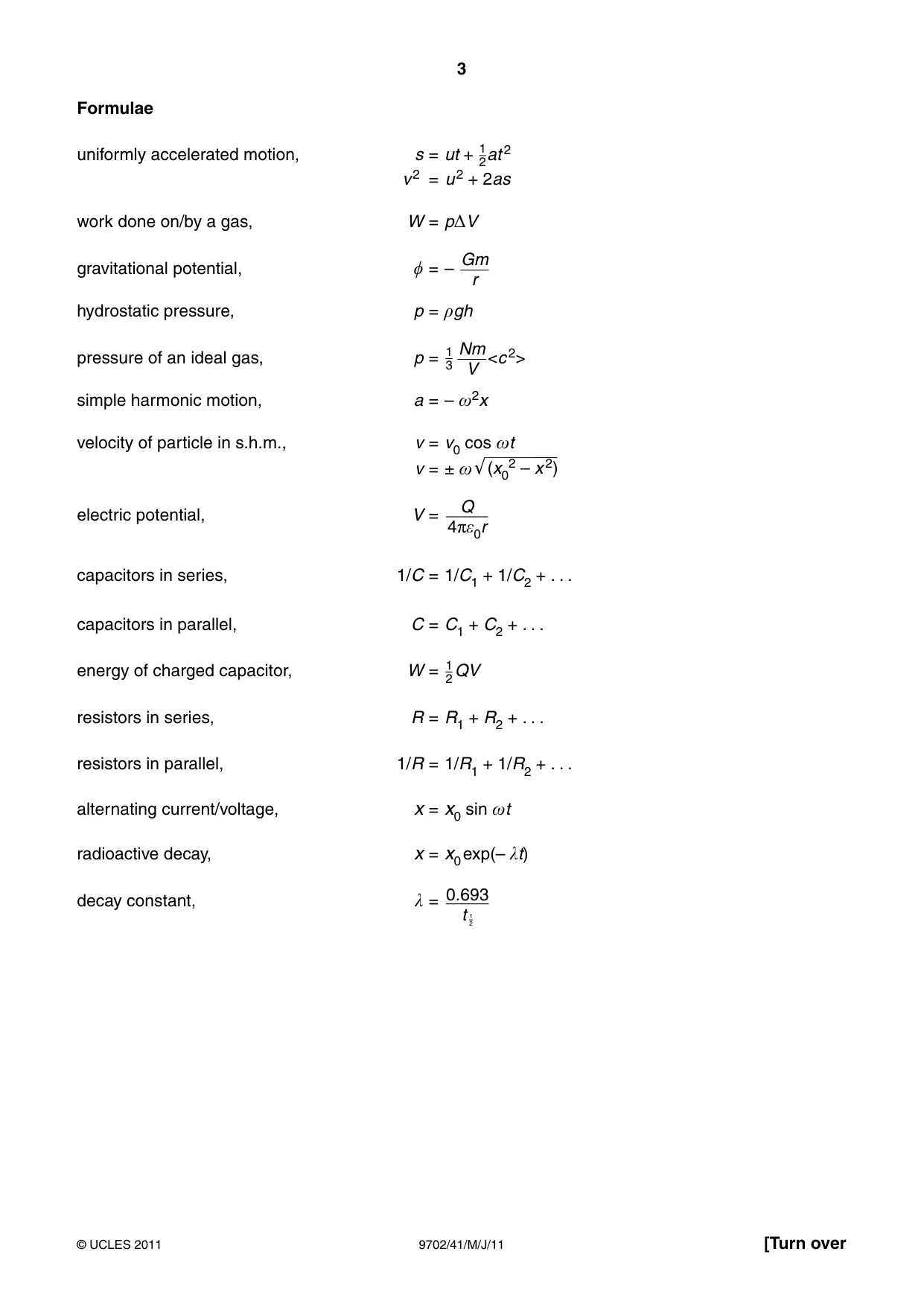
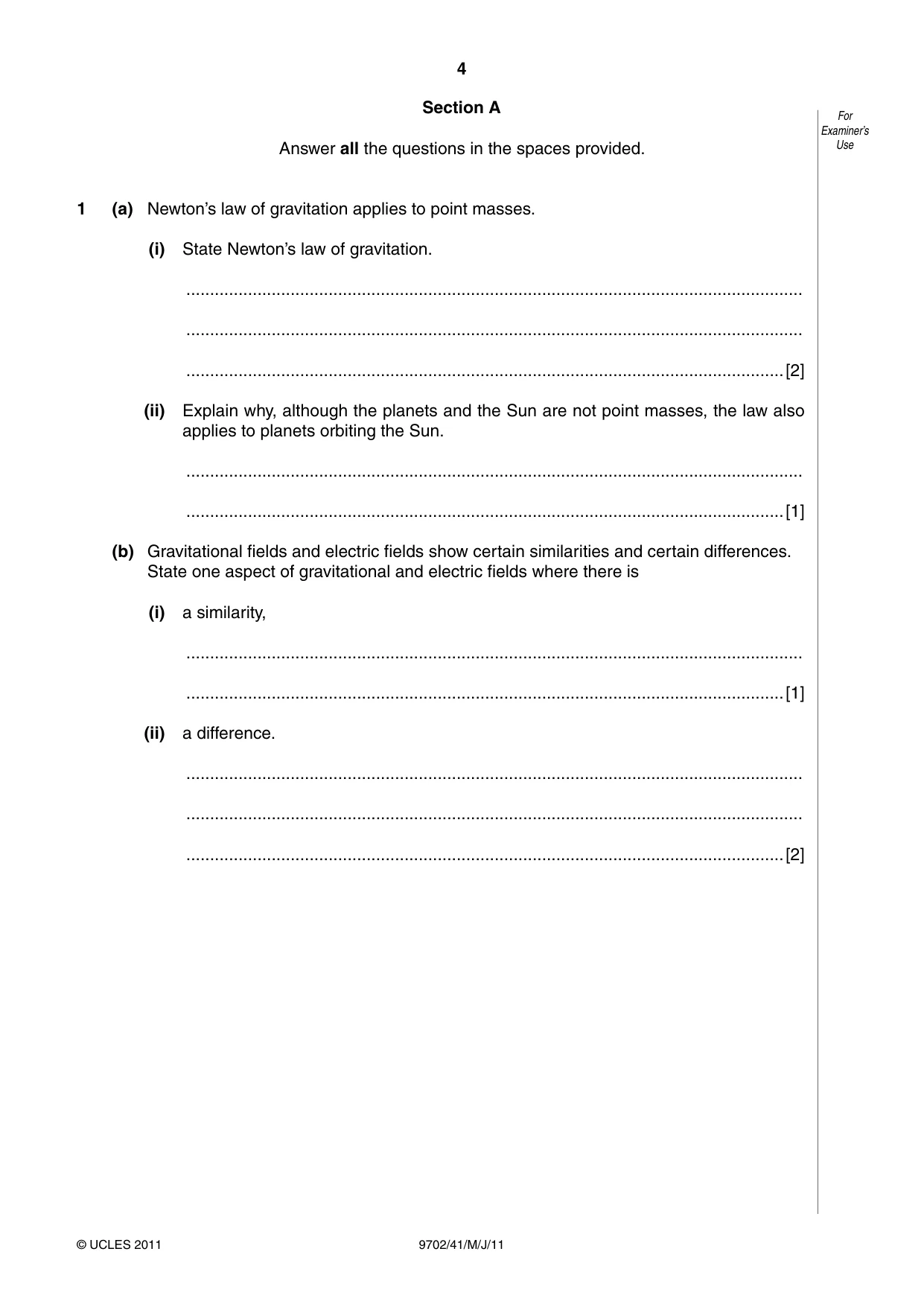


Mark scheme5 pages
Answers below. Sit the paper first if you are practising.
Questions as text
Q1 · Newton’s law of gravitation applies to point masses
1 (a) Newton’s law of gravitation applies to point masses. (i) State Newton’s law of gravitation. .................................................................................................................................. .................................................................................................................................. ..............................................................................................................................[2] (ii) Explain why, although the planets and the Sun are not point masses, the law also applies to planets orbiting the Sun. .................................................................................................................................. ..............................................................................................................................[1] (b) Gravitational fields and electric fields show certain similarities and certain differences. State one aspect of gravitational and electric fields where there is (i) a similarity, .................................................................................................................................. ..............................................................................................................................[1] (ii) a difference. .................................................................................................................................. .................................................................................................................................. ..............................................................................................................................[2]
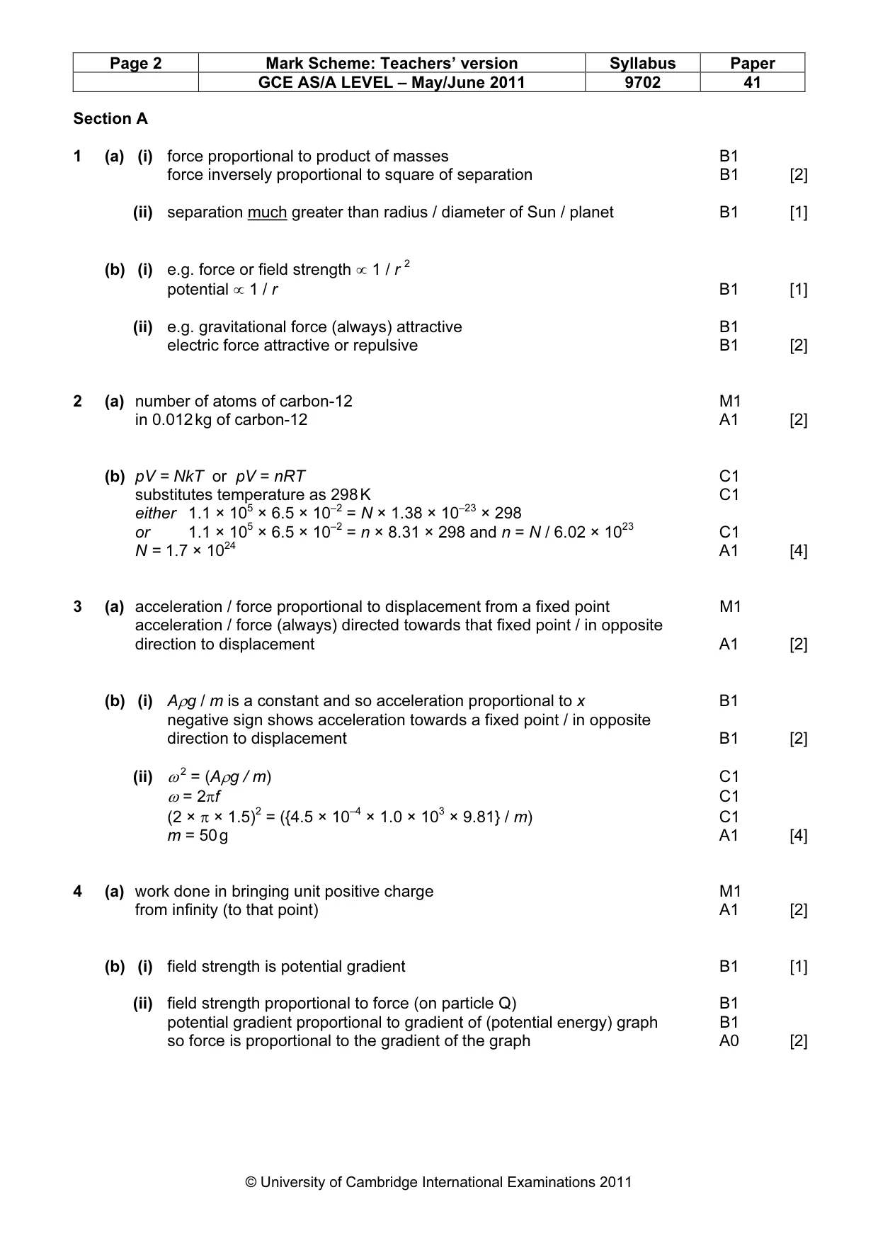
Mark scheme: 1 (a) (i) force proportional to product of masses B1 force inversely proportional to square of separation B1 [2] (ii) separation much greater than radius / diameter of Sun / planet B1 [1] (b) (i) e.g. force or field strength ∝ 1 / r 2 potential ∝ 1 / r B1 [1] (ii) e.g. gravitational force (always) attractive B1 electric force attractive or repulsive B1 [2]
Q2 · State what is meant by the Avogadro constant NA
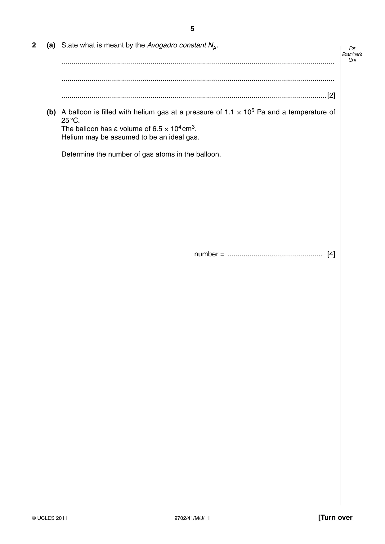
2 (a) State what is meant by the Avogadro constant NA. For Examiner’s .......................................................................................................................................... Use .......................................................................................................................................... ......................................................................................................................................[2] (b) A balloon is filled with helium gas at a pressure of 1.1 × 10⁵ Pa and a temperature of 25 °C. The balloon has a volume of 6.5 × 104 cm3. Helium may be assumed to be an ideal gas. Determine the number of gas atoms in the balloon. number = ................................................ [4]
Mark scheme: 2 (a) number of atoms of carbon-12 M1 in 0.012 kg of carbon-12 A1 [2] (b) pV = NkT or pV = nRT C1 substitutes temperature as 298 K C1 either 1.1 × 105 × 6.5 × 10–2 = N × 1.38 × 10–23 × 298 or 1.1 × 105 × 6.5 × 10–2 = n × 8.31 × 298 and n = N / 6.02 × 10²³ C1 N = 1.7 × 1024 A1 [4]
Q3 · Define simple harmonic motion
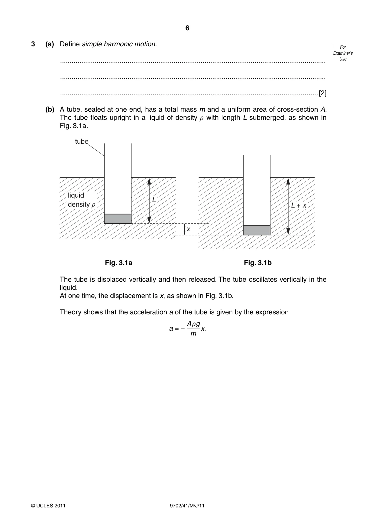
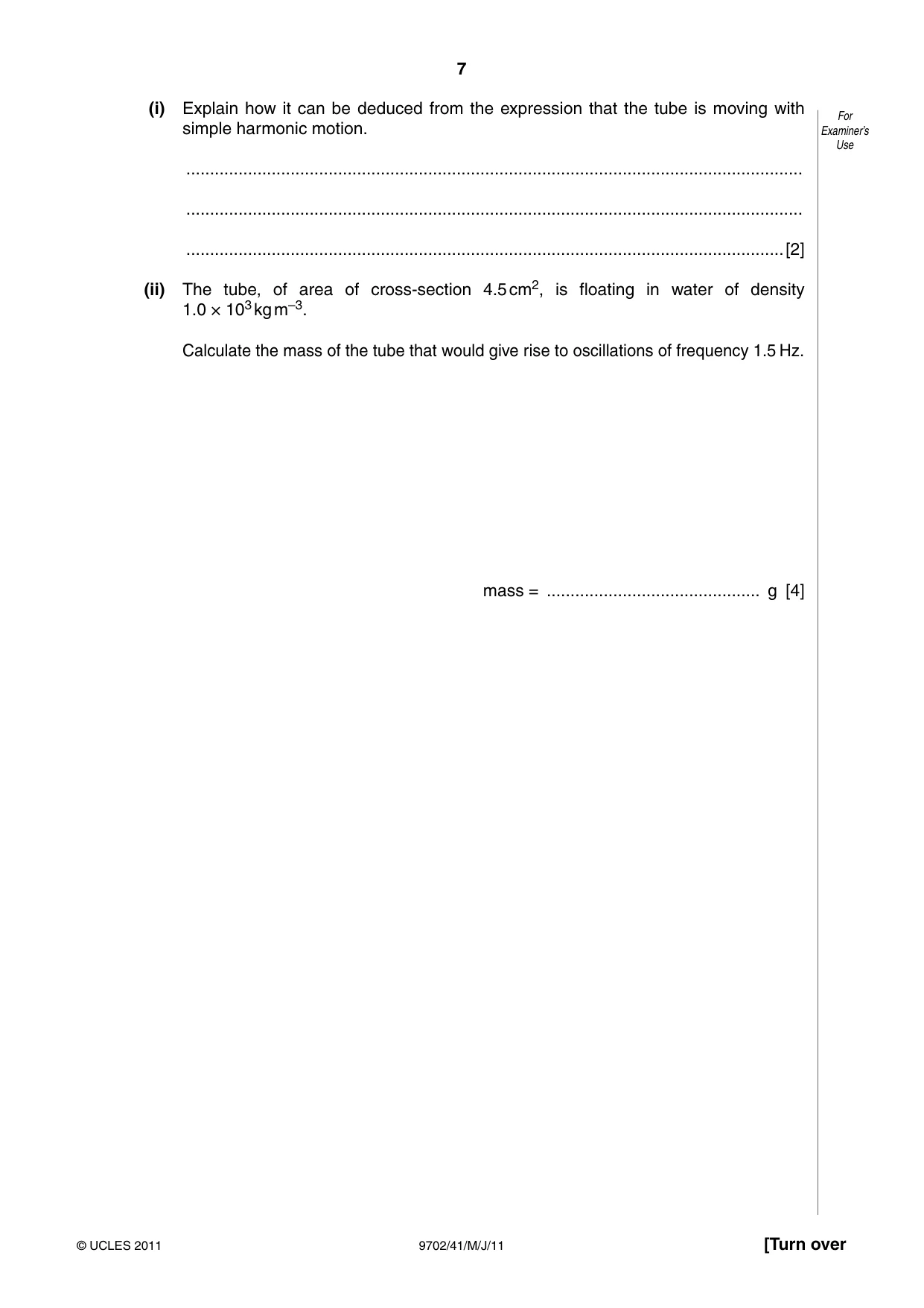
3 (a) Define simple harmonic motion. For Examiner’s .......................................................................................................................................... Use .......................................................................................................................................... ......................................................................................................................................[2] (b) A tube, sealed at one end, has a total mass m and a uniform area of cross-section A. The tube floats upright in a liquid of density ρ with length L submerged, as shown in Fig. 3.1a. tube liquid LL density ρ LL +++ xx x Fig. 3.1a Fig. 3.1b The tube is displaced vertically and then released. The tube oscillates vertically in the liquid. At one time, the displacement is x, as shown in Fig. 3.1b. Theory shows that the acceleration a of the tube is given by the expression A ρg a = – x. m (i) Explain how it can be deduced from the expression that the tube is moving with For simple harmonic motion. Examiner’s Use .................................................................................................................................. .................................................................................................................................. ..............................................................................................................................[2] (ii) The tube, of area of cross-section 4.5 cm2, is floating in water of density 1.0 × 10³ kg m–3. Calculate the mass of the tube that would give rise to oscillations of frequency 1.5 Hz. mass = ............................................. g [4]
Mark scheme: 3 (a) acceleration / force proportional to displacement from a fixed point M1 acceleration / force (always) directed towards that fixed point / in opposite direction to displacement A1 [2] (b) (i) Aρg / m is a constant and so acceleration proportional to x B1 negative sign shows acceleration towards a fixed point / in opposite direction to displacement B1 [2] (ii) ω 2 = (Aρg / m) C1 ω = 2πf C1 (2 × π × 1.5)2 = ({4.5 × 10–4 × 1.0 × 103 × 9.81} / m) C1 m = 50 g A1 [4]
Q4 · Define electric potential at a point
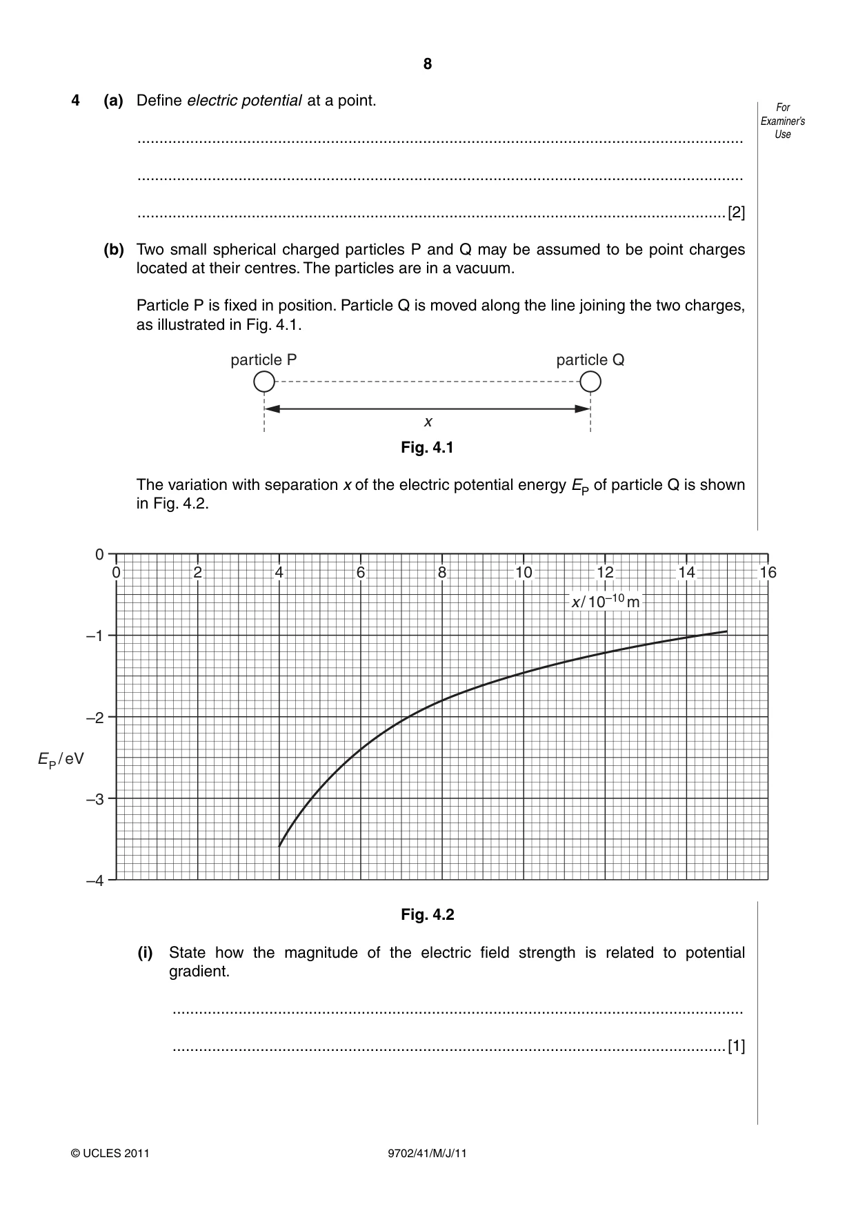
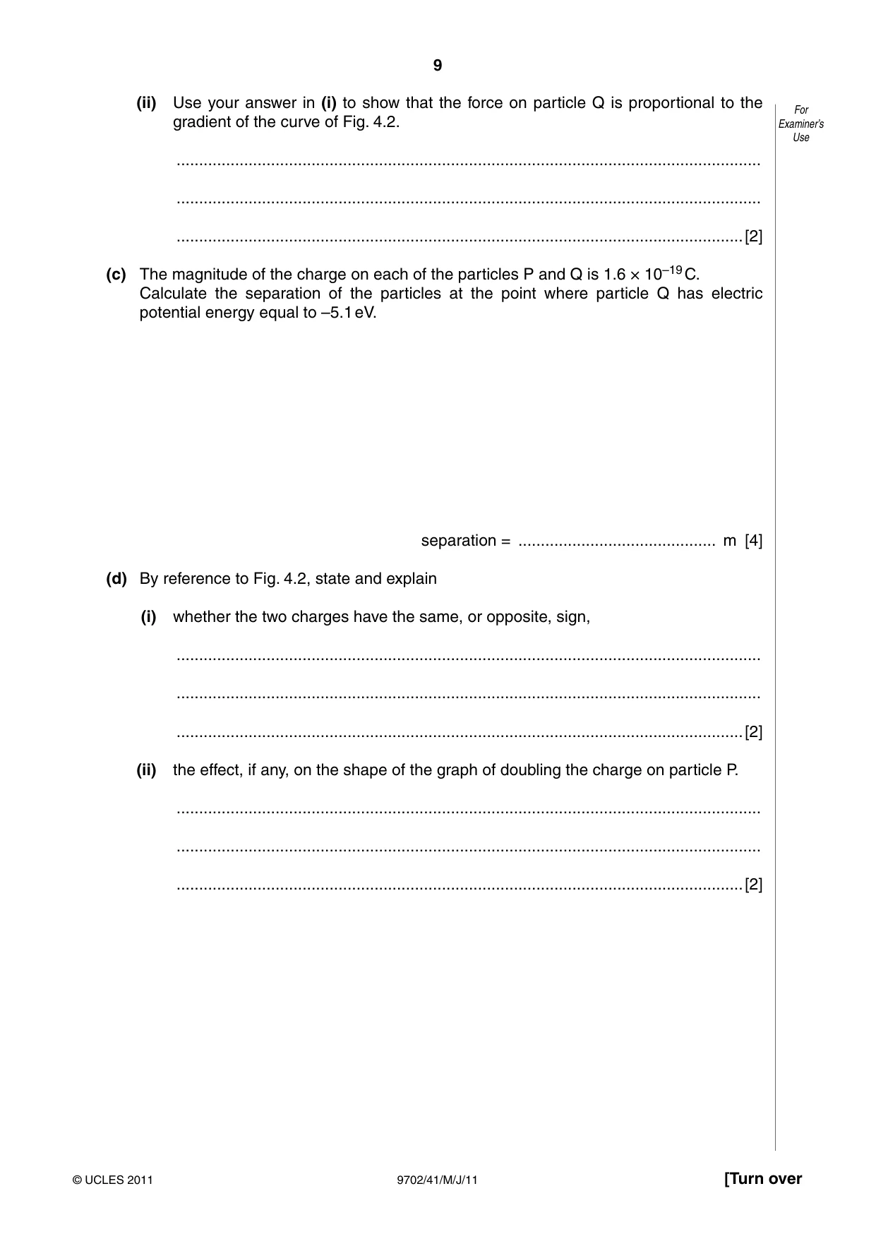
4 (a) Define electric potential at a point. For Examiner’s .......................................................................................................................................... Use .......................................................................................................................................... ......................................................................................................................................[2] (b) Two small spherical charged particles P and Q may be assumed to be point charges located at their centres. The particles are in a vacuum. Particle P is fixed in position. Particle Q is moved along the line joining the two charges, as illustrated in Fig. 4.1. particle P particle Q x Fig. 4.1 The variation with separation x of the electric potential energy EP of particle Q is shown in Fig. 4.2. 0 0 2 4 6 8 10 12 14 16 x / 10–10 m –1 –2 E / eV P –3 –4 Fig. 4.2 (i) State how the magnitude of the electric field strength is related to potential gradient. .................................................................................................................................. ..............................................................................................................................[1] (ii) Use your answer in (i) to show that the force on particle Q is proportional to the For gradient of the curve of Fig. 4.2. Examiner’s Use .................................................................................................................................. .................................................................................................................................. ..............................................................................................................................[2] (c) The magnitude of the charge on each of the particles P and Q is 1.6 × 10⁻¹⁹ C. Calculate the separation of the particles at the point where particle Q has electric potential energy equal to –5.1 eV. separation = ............................................ m [4] (d) By reference to Fig. 4.2, state and explain (i) whether the two charges have the same, or opposite, sign, .................................................................................................................................. .................................................................................................................................. ..............................................................................................................................[2] (ii) the effect, if any, on the shape of the graph of doubling the charge on particle P. .................................................................................................................................. .................................................................................................................................. ..............................................................................................................................[2]
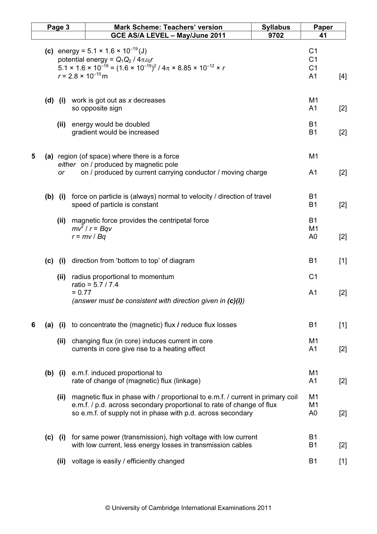
Mark scheme: 4 (a) work done in bringing unit positive charge M1 from infinity (to that point) A1 [2] (b) (i) field strength is potential gradient B1 [1] (ii) field strength proportional to force (on particle Q) B1 potential gradient proportional to gradient of (potential energy) graph B1 so force is proportional to the gradient of the graph A0 [2] GCE AS/A LEVEL – May/June 2011 9702 41 (c) energy = 5.1 × 1.6 × 10–19 (J) C1 potential energy = Q1Q2 / 4πε0r C1 5.1 × 1.6 × 10–19 = (1.6 × 10⁻¹⁹)2 / 4π × 8.85 × 10–12 × r C1 r = 2.8 × 10⁻¹⁰ m A1 [4] (d) (i) work is got out as x decreases M1 so opposite sign A1 [2] (ii) energy would be doubled B1 gradient would be increased B1 [2]
Q5 · State what is meant by a magnetic field
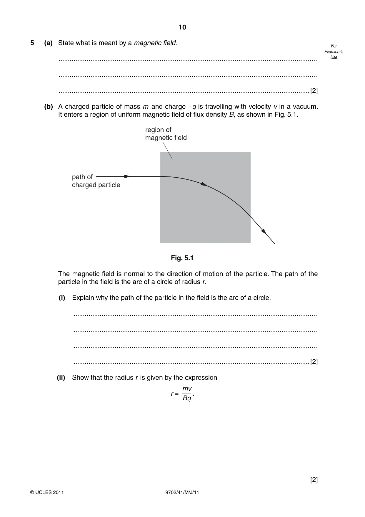
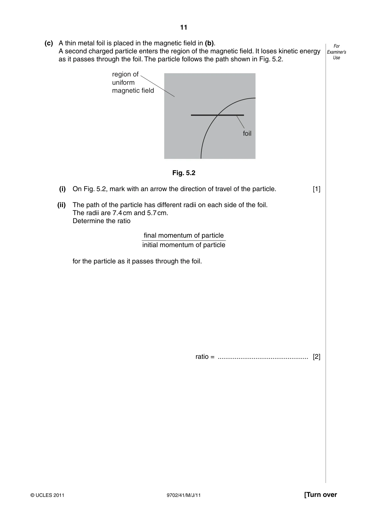
5 (a) State what is meant by a magnetic field. For Examiner’s .......................................................................................................................................... Use .......................................................................................................................................... ......................................................................................................................................[2] (b) A charged particle of mass m and charge +q is travelling with velocity v in a vacuum. It enters a region of uniform magnetic field of flux density B, as shown in Fig. 5.1. region of magnetic field path of charged particle Fig. 5.1 The magnetic field is normal to the direction of motion of the particle. The path of the particle in the field is the arc of a circle of radius r. (i) Explain why the path of the particle in the field is the arc of a circle. .................................................................................................................................. .................................................................................................................................. .................................................................................................................................. ..............................................................................................................................[2] (ii) Show that the radius r is given by the expression mv r = . Bq [2] (c) A thin metal foil is placed in the magnetic field in (b). For A second charged particle enters the region of the magnetic field. It loses kinetic energy Examiner’s as it passes through the foil. The particle follows the path shown in Fig. 5.2. Use region of uniform magnetic field foil Fig. 5.2 (i) On Fig. 5.2, mark with an arrow the direction of travel of the particle. [1] (ii) The path of the particle has different radii on each side of the foil. The radii are 7.4 cm and 5.7 cm. Determine the ratio final momentum of particle initial momentum of particle for the particle as it passes through the foil. ratio = ................................................ [2]
Mark scheme: 5 (a) region (of space) where there is a force M1 either on / produced by magnetic pole or on / produced by current carrying conductor / moving charge A1 [2] (b) (i) force on particle is (always) normal to velocity / direction of travel B1 speed of particle is constant B1 [2] (ii) magnetic force provides the centripetal force B1 mv2 / r = Bqv M1 r = mv / Bq A0 [2] (c) (i) direction from ‘bottom to top’ of diagram B1 [1] (ii) radius proportional to momentum C1 ratio = 5.7 / 7.4 = 0.77 A1 [2] (answer must be consistent with direction given in (c)(i))
Q6 · A transformer is illustrated in Fig
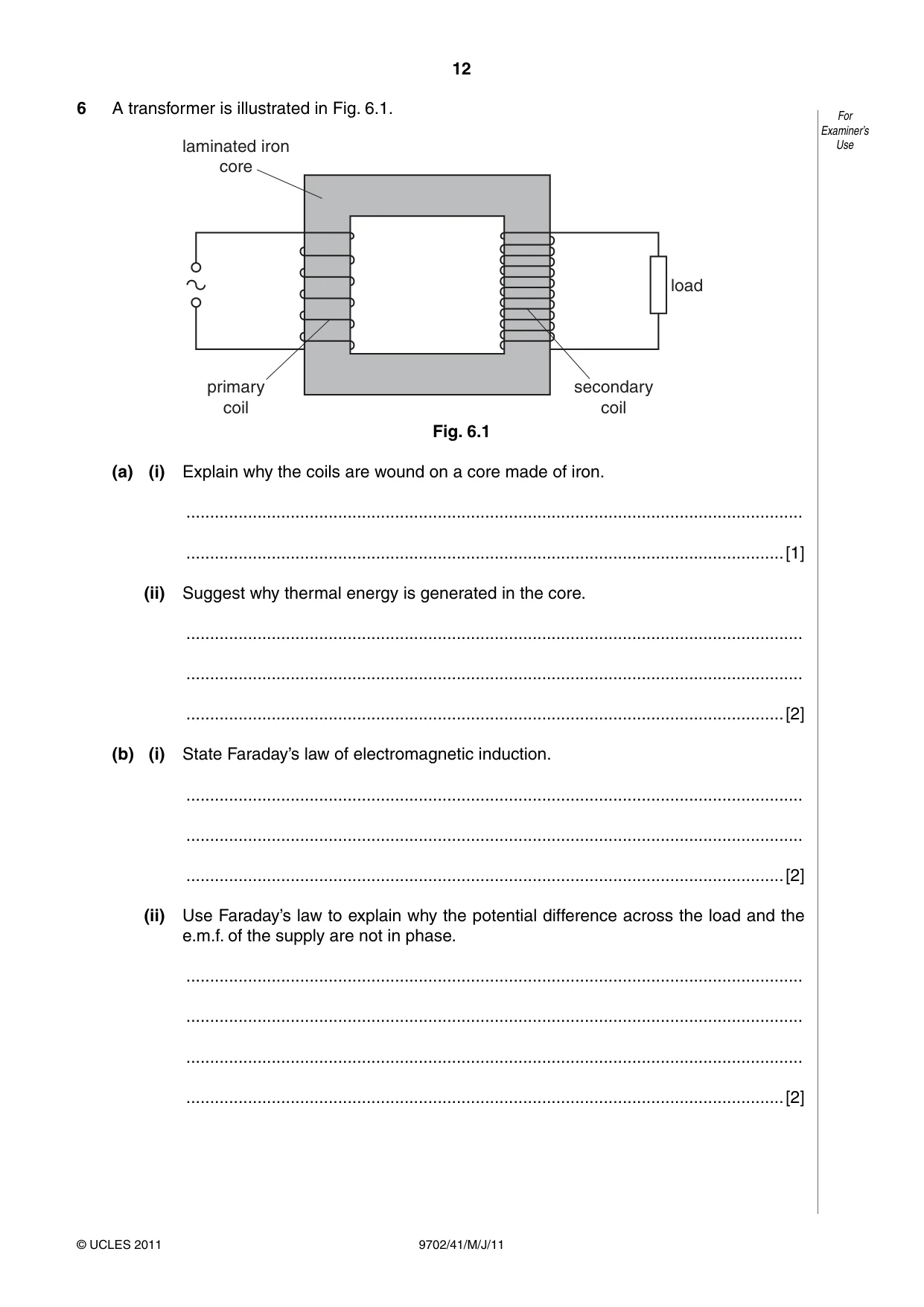
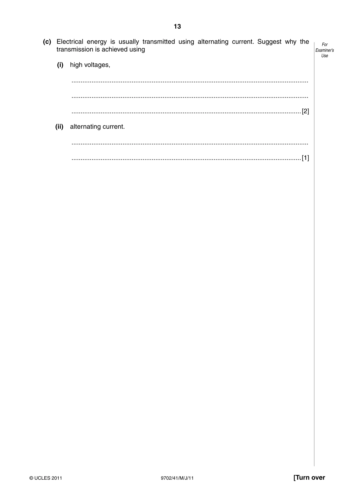
6 A transformer is illustrated in Fig. 6.1. For Examiner’s laminated iron Use core load primary secondary coil coil Fig. 6.1 (a) (i) Explain why the coils are wound on a core made of iron. .................................................................................................................................. ..............................................................................................................................[1] (ii) Suggest why thermal energy is generated in the core. .................................................................................................................................. .................................................................................................................................. ..............................................................................................................................[2] (b) (i) State Faraday’s law of electromagnetic induction. .................................................................................................................................. .................................................................................................................................. ..............................................................................................................................[2] (ii) Use Faraday’s law to explain why the potential difference across the load and the e.m.f. of the supply are not in phase. .................................................................................................................................. .................................................................................................................................. .................................................................................................................................. ..............................................................................................................................[2] (c) Electrical energy is usually transmitted using alternating current. Suggest why the For transmission is achieved using Examiner’s Use (i) high voltages, .................................................................................................................................. .................................................................................................................................. ..............................................................................................................................[2] (ii) alternating current. .................................................................................................................................. ..............................................................................................................................[1]
Mark scheme: 6 (a) (i) to concentrate the (magnetic) flux / reduce flux losses B1 [1] (ii) changing flux (in core) induces current in core M1 currents in core give rise to a heating effect A1 [2] (b) (i) e.m.f. induced proportional to M1 rate of change of (magnetic) flux (linkage) A1 [2] (ii) magnetic flux in phase with / proportional to e.m.f. / current in primary coil M1 e.m.f. / p.d. across secondary proportional to rate of change of flux M1 so e.m.f. of supply not in phase with p.d. across secondary A0 [2] (c) (i) for same power (transmission), high voltage with low current B1 with low current, less energy losses in transmission cables B1 [2] (ii) voltage is easily / efficiently changed B1 [1] GCE AS/A LEVEL – May/June 2011 9702 41
Q7 · Experiments are conducted to investigate the photoelectric effect
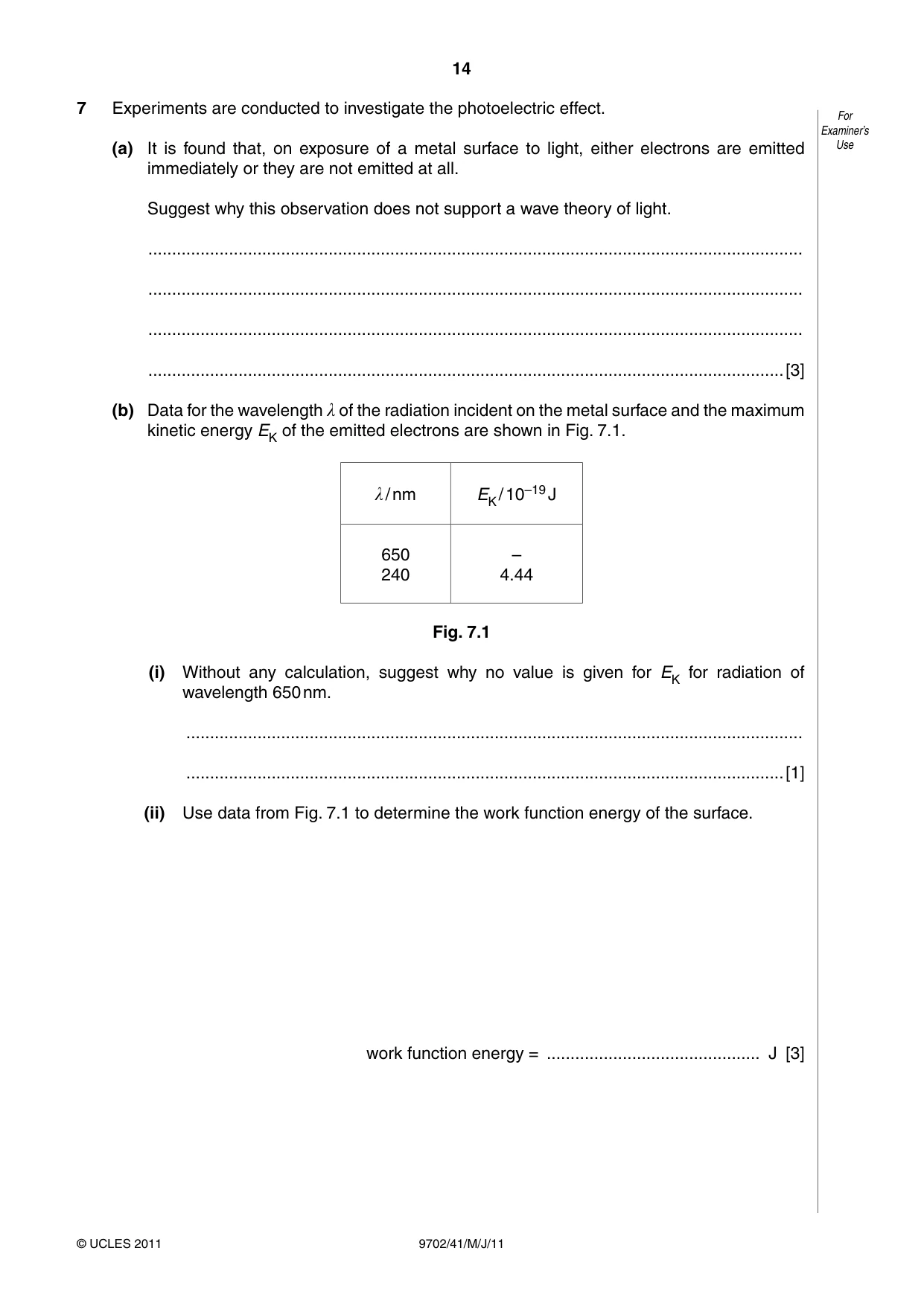
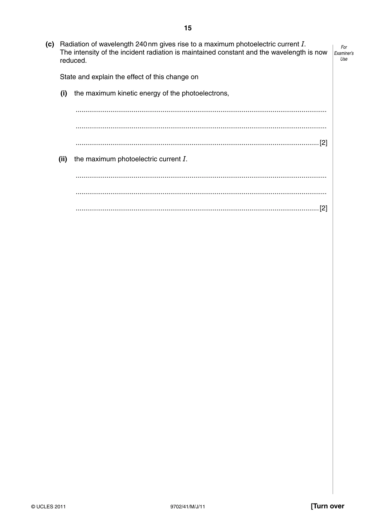
7 Experiments are conducted to investigate the photoelectric effect. For Examiner’s (a) It is found that, on exposure of a metal surface to light, either electrons are emitted Use immediately or they are not emitted at all. Suggest why this observation does not support a wave theory of light. .......................................................................................................................................... .......................................................................................................................................... .......................................................................................................................................... ......................................................................................................................................[3] (b) Data for the wavelength λ of the radiation incident on the metal surface and the maximum kinetic energy EK of the emitted electrons are shown in Fig. 7.1. λ / nm EK / 10–19 J 650 – 240 4.44 Fig. 7.1 (i) Without any calculation, suggest why no value is given for EK for radiation of wavelength 650 nm. .................................................................................................................................. ..............................................................................................................................[1] (ii) Use data from Fig. 7.1 to determine the work function energy of the surface. work function energy = ............................................. J [3] (c) Radiation of wavelength 240 nm gives rise to a maximum photoelectric current I. For The intensity of the incident radiation is maintained constant and the wavelength is now Examiner’s reduced. Use State and explain the effect of this change on (i) the maximum kinetic energy of the photoelectrons, .................................................................................................................................. .................................................................................................................................. ..............................................................................................................................[2] (ii) the maximum photoelectric current I. .................................................................................................................................. .................................................................................................................................. ..............................................................................................................................[2]
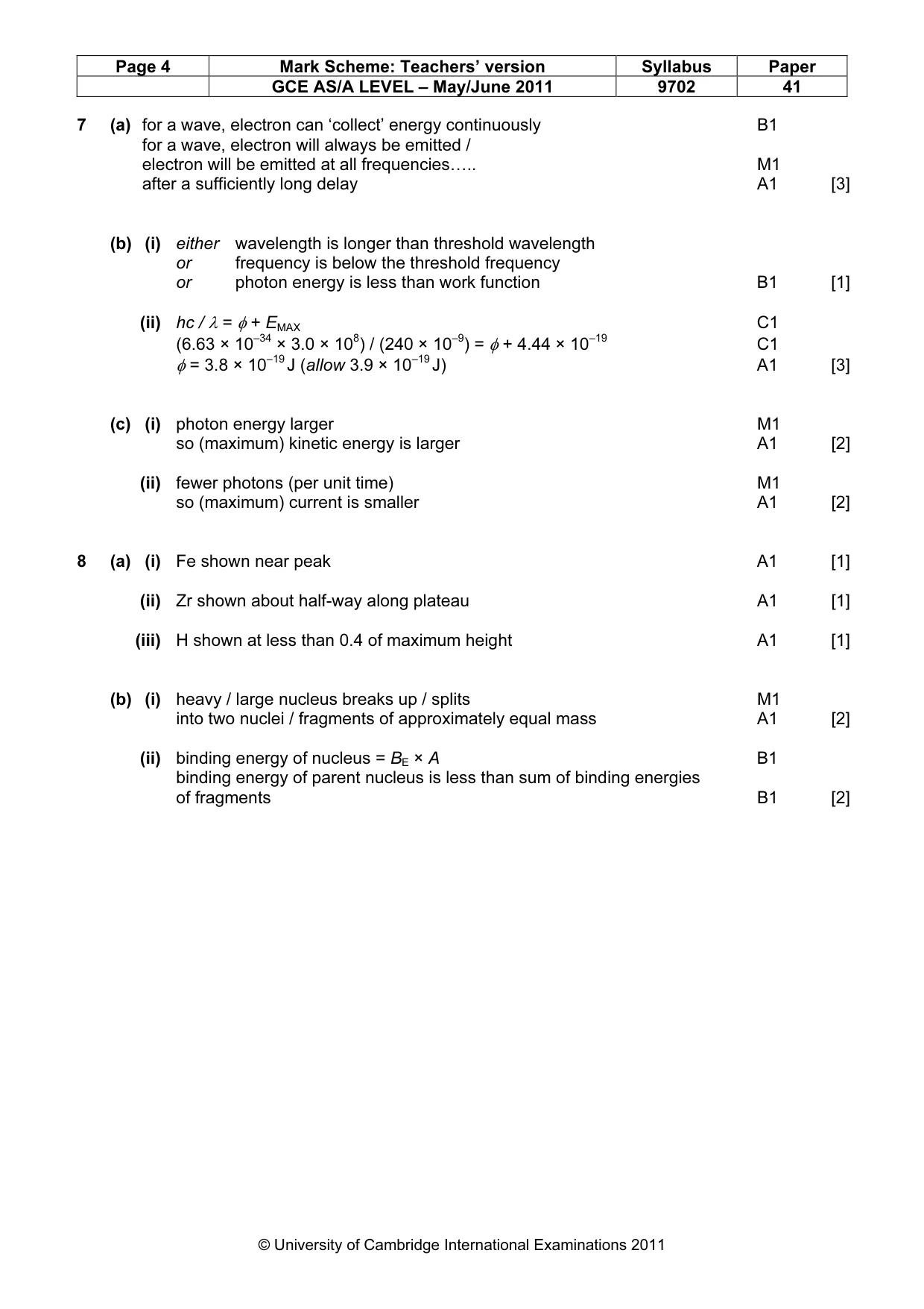
Mark scheme: 7 (a) for a wave, electron can ‘collect’ energy continuously B1 for a wave, electron will always be emitted / electron will be emitted at all frequencies….. M1 after a sufficiently long delay A1 [3] (b) (i) either wavelength is longer than threshold wavelength or frequency is below the threshold frequency or photon energy is less than work function B1 [1] (ii) hc / λ = φ + EMAX C1 (6.63 × 10–34 × 3.0 × 108) / (240 × 10–9) = φ + 4.44 × 10⁻¹⁹ C1 φ = 3.8 × 10⁻¹⁹ J (allow 3.9 × 10⁻¹⁹ J) A1 [3] (c) (i) photon energy larger M1 so (maximum) kinetic energy is larger A1 [2] (ii) fewer photons (per unit time) M1 so (maximum) current is smaller A1 [2]
Q8 · The variation with nucleon number A of the binding energy per nucleon BE of nuclei is For…
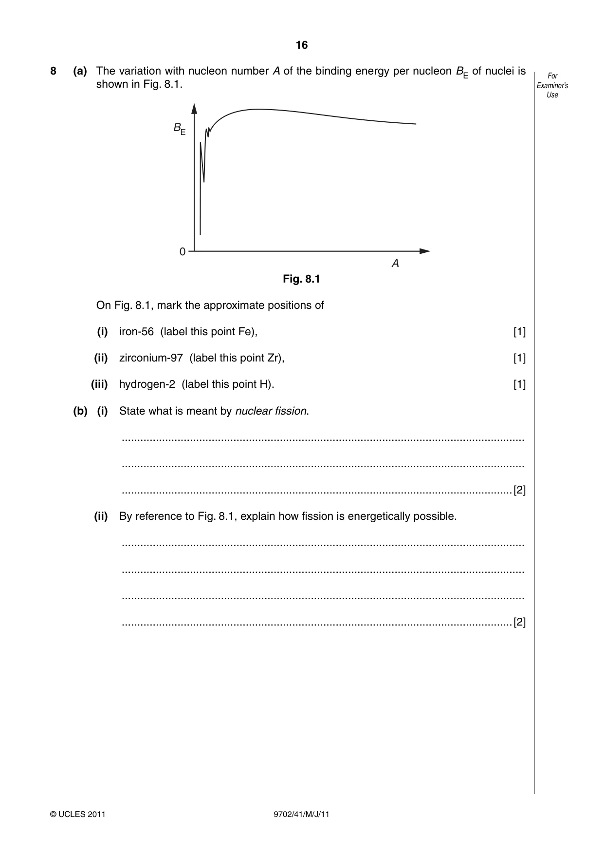
8 (a) The variation with nucleon number A of the binding energy per nucleon BE of nuclei is For shown in Fig. 8.1. Examiner’s Use BE 0 A Fig. 8.1 On Fig. 8.1, mark the approximate positions of (i) iron-56 (label this point Fe), [1] (ii) zirconium-97 (label this point Zr), [1] (iii) hydrogen-2 (label this point H). [1] (b) (i) State what is meant by nuclear fission. .................................................................................................................................. .................................................................................................................................. ..............................................................................................................................[2] (ii) By reference to Fig. 8.1, explain how fission is energetically possible. .................................................................................................................................. .................................................................................................................................. .................................................................................................................................. ..............................................................................................................................[2]
Mark scheme: 8 (a) (i) Fe shown near peak A1 [1] (ii) Zr shown about half-way along plateau A1 [1] (iii) H shown at less than 0.4 of maximum height A1 [1] (b) (i) heavy / large nucleus breaks up / splits M1 into two nuclei / fragments of approximately equal mass A1 [2] (ii) binding energy of nucleus = BE × A B1 binding energy of parent nucleus is less than sum of binding energies of fragments B1 [2] GCE AS/A LEVEL – May/June 2011 9702 41 Section B
Q9 · An operational amplifier (op-amp) may be used as a comparator
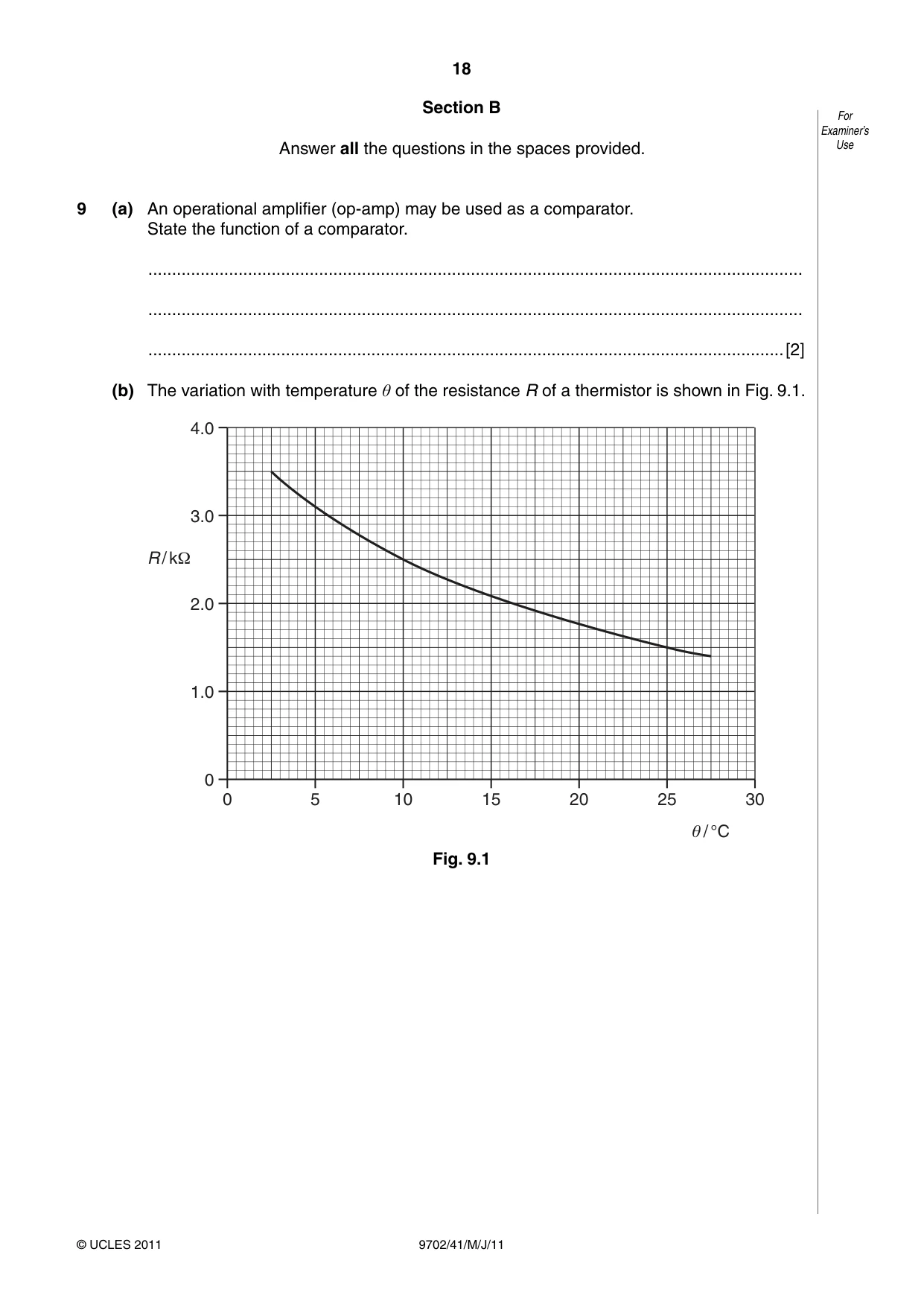
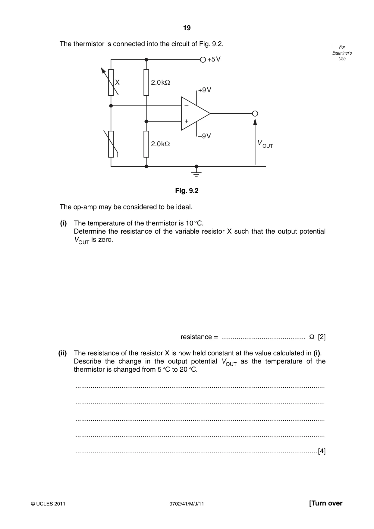
9 (a) An operational amplifier (op-amp) may be used as a comparator. State the function of a comparator. .......................................................................................................................................... .......................................................................................................................................... ......................................................................................................................................[2] (b) The variation with temperature θ of the resistance R of a thermistor is shown in Fig. 9.1. 4.0 3.0 R / kΩ 2.0 1.0 0 0 5 10 15 20 25 30 θ / °C Fig. 9.1 The thermistor is connected into the circuit of Fig. 9.2. For Examiner’s +5V Use X 2.0kΩ +9V – + –9V 2.0kΩ V OUT Fig. 9.2 The op-amp may be considered to be ideal. (i) The temperature of the thermistor is 10 °C. Determine the resistance of the variable resistor X such that the output potential VOUT is zero. resistance = ............................................ Ω [2] (ii) The resistance of the resistor X is now held constant at the value calculated in (i). Describe the change in the output potential VOUT as the temperature of the thermistor is changed from 5 °C to 20 °C. .................................................................................................................................. .................................................................................................................................. .................................................................................................................................. .................................................................................................................................. ..............................................................................................................................[4]
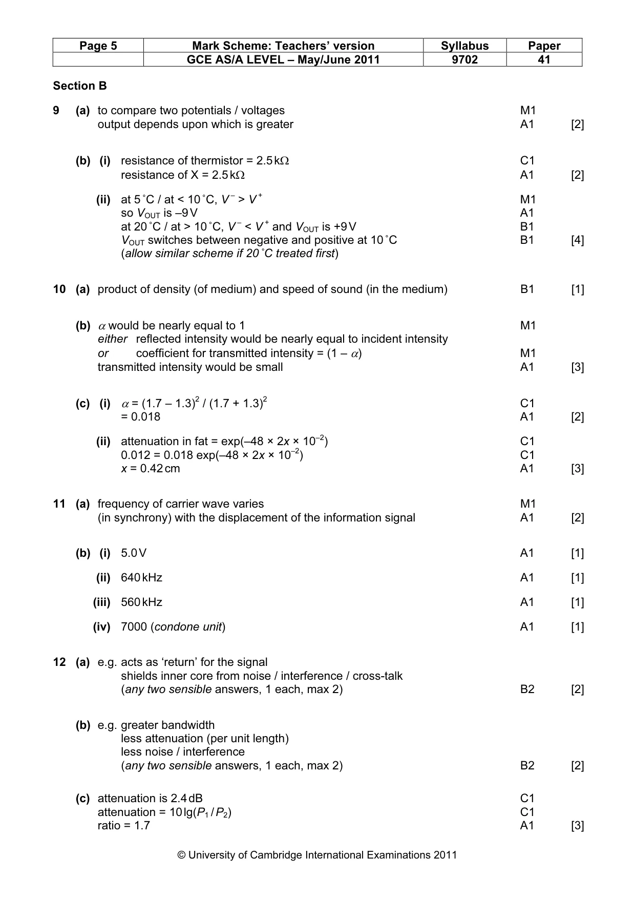
Mark scheme: 9 (a) to compare two potentials / voltages M1 output depends upon which is greater A1 [2] (b) (i) resistance of thermistor = 2.5 kΩ C1 resistance of X = 2.5 kΩ A1 [2] (ii) at 5 ˚C / at < 10 ˚C, V – > V + M1 so VOUT is –9 V A1 at 20 ˚C / at > 10 ˚C, V – < V + and VOUT is +9 V B1 VOUT switches between negative and positive at 10 ˚C B1 [4] (allow similar scheme if 20 ˚C treated first)
Q10 · State what is meant by the acoustic impedance Z of a medium
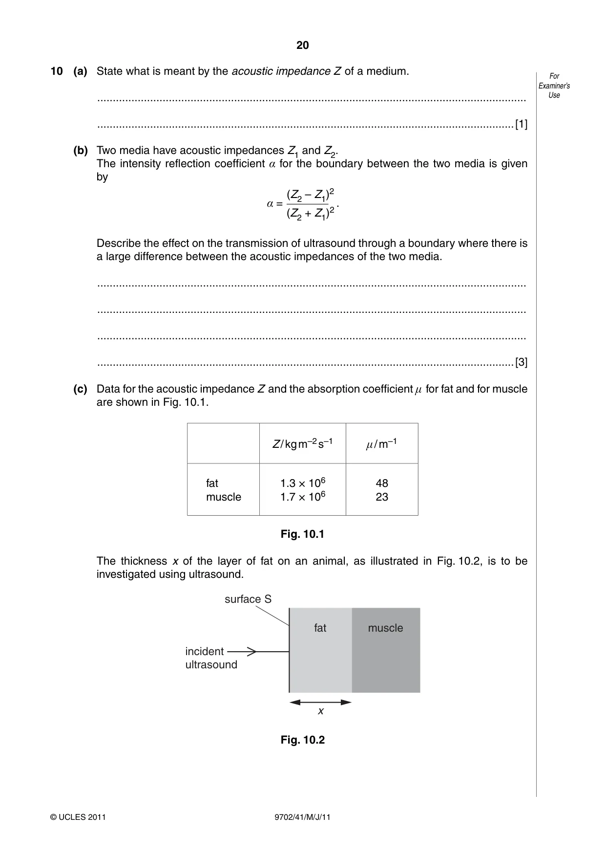
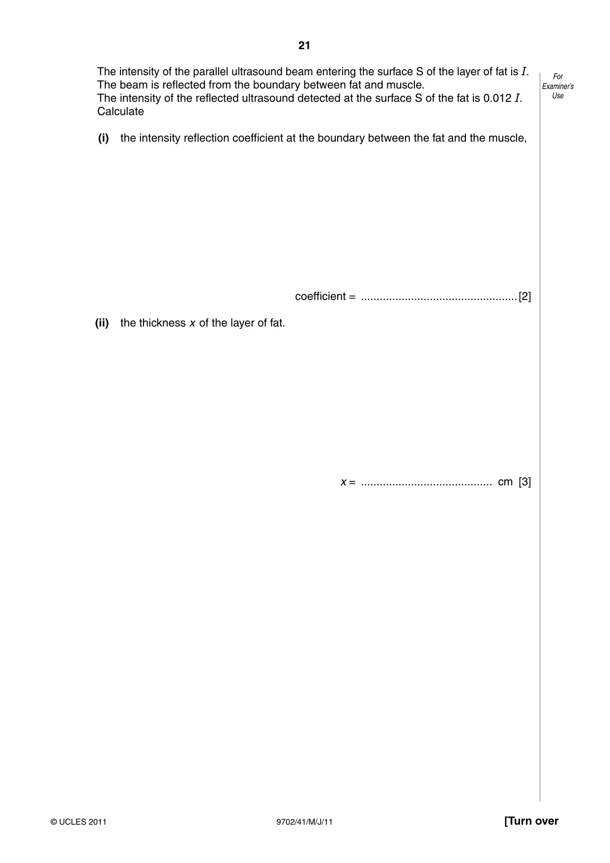
10 (a) State what is meant by the acoustic impedance Z of a medium. For Examiner’s .......................................................................................................................................... Use ......................................................................................................................................[1] (b) Two media have acoustic impedances Z1 and Z2. The intensity reflection coefficient α for the boundary between the two media is given by (Z2 – Z1)2 α = . (Z2 + Z1)2 Describe the effect on the transmission of ultrasound through a boundary where there is a large difference between the acoustic impedances of the two media. .......................................................................................................................................... .......................................................................................................................................... .......................................................................................................................................... ......................................................................................................................................[3] (c) Data for the acoustic impedance Z and the absorption coefficient μ for fat and for muscle are shown in Fig. 10.1. Z / kg m–2 s–1 μ / m–1 fat 1.3 × 10⁶ 48 muscle 1.7 × 10⁶ 23 Fig. 10.1 The thickness x of the layer of fat on an animal, as illustrated in Fig. 10.2, is to be investigated using ultrasound. surface S fat muscle incident ultrasound x Fig. 10.2 The intensity of the parallel ultrasound beam entering the surface S of the layer of fat is I. For The beam is reflected from the boundary between fat and muscle. Examiner’s The intensity of the reflected ultrasound detected at the surface S of the fat is 0.012 I. Use Calculate (i) the intensity reflection coefficient at the boundary between the fat and the muscle, coefficient = ..................................................[2] (ii) the thickness x of the layer of fat. x = .......................................... cm [3]
Mark scheme: 10 (a) product of density (of medium) and speed of sound (in the medium) B1 [1] (b) α would be nearly equal to 1 M1 either reflected intensity would be nearly equal to incident intensity or coefficient for transmitted intensity = (1 – α) M1 transmitted intensity would be small A1 [3] (c) (i) α = (1.7 – 1.3)2 / (1.7 + 1.3)2 C1 = 0.018 A1 [2] (ii) attenuation in fat = exp(–48 × 2x × 10–2) C1 0.012 = 0.018 exp(–48 × 2x × 10–2) C1 x = 0.42 cm A1 [3]
Q11 · Describe what is meant by frequency modulation (FM )
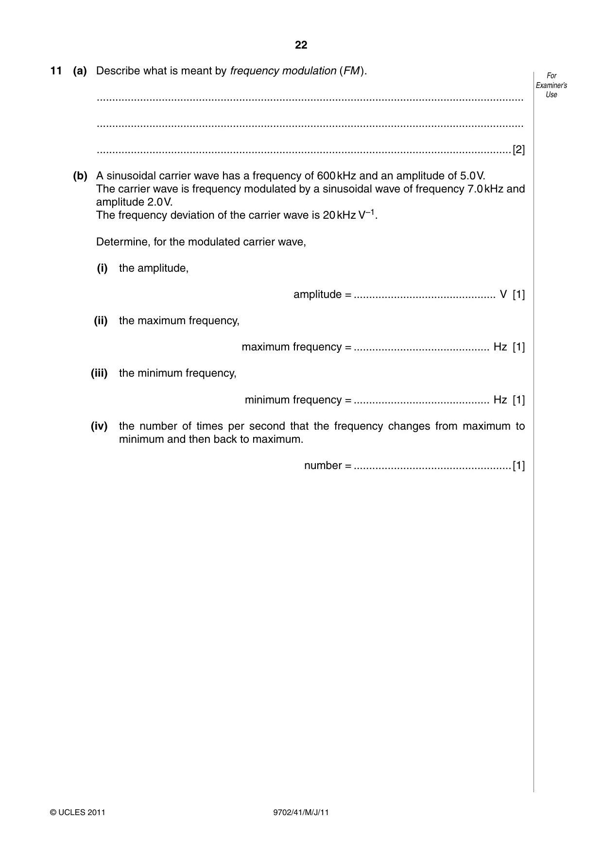
11 (a) Describe what is meant by frequency modulation (FM ). For Examiner’s .......................................................................................................................................... Use .......................................................................................................................................... ......................................................................................................................................[2] (b) A sinusoidal carrier wave has a frequency of 600 kHz and an amplitude of 5.0 V. The carrier wave is frequency modulated by a sinusoidal wave of frequency 7.0 kHz and amplitude 2.0 V. The frequency deviation of the carrier wave is 20 kHz V–1. Determine, for the modulated carrier wave, (i) the amplitude, amplitude = .............................................. V [1] (ii) the maximum frequency, maximum frequency = ............................................ Hz [1] (iii) the minimum frequency, minimum frequency = ............................................ Hz [1] (iv) the number of times per second that the frequency changes from maximum to minimum and then back to maximum. number = ...................................................[1]
Mark scheme: 11 (a) frequency of carrier wave varies M1 (in synchrony) with the displacement of the information signal A1 [2] (b) (i) 5.0 V A1 [1] (ii) 640 kHz A1 [1] (iii) 560 kHz A1 [1] (iv) 7000 (condone unit) A1 [1]
Q12 · Many television receivers are connected to an aerial using a coaxial cable
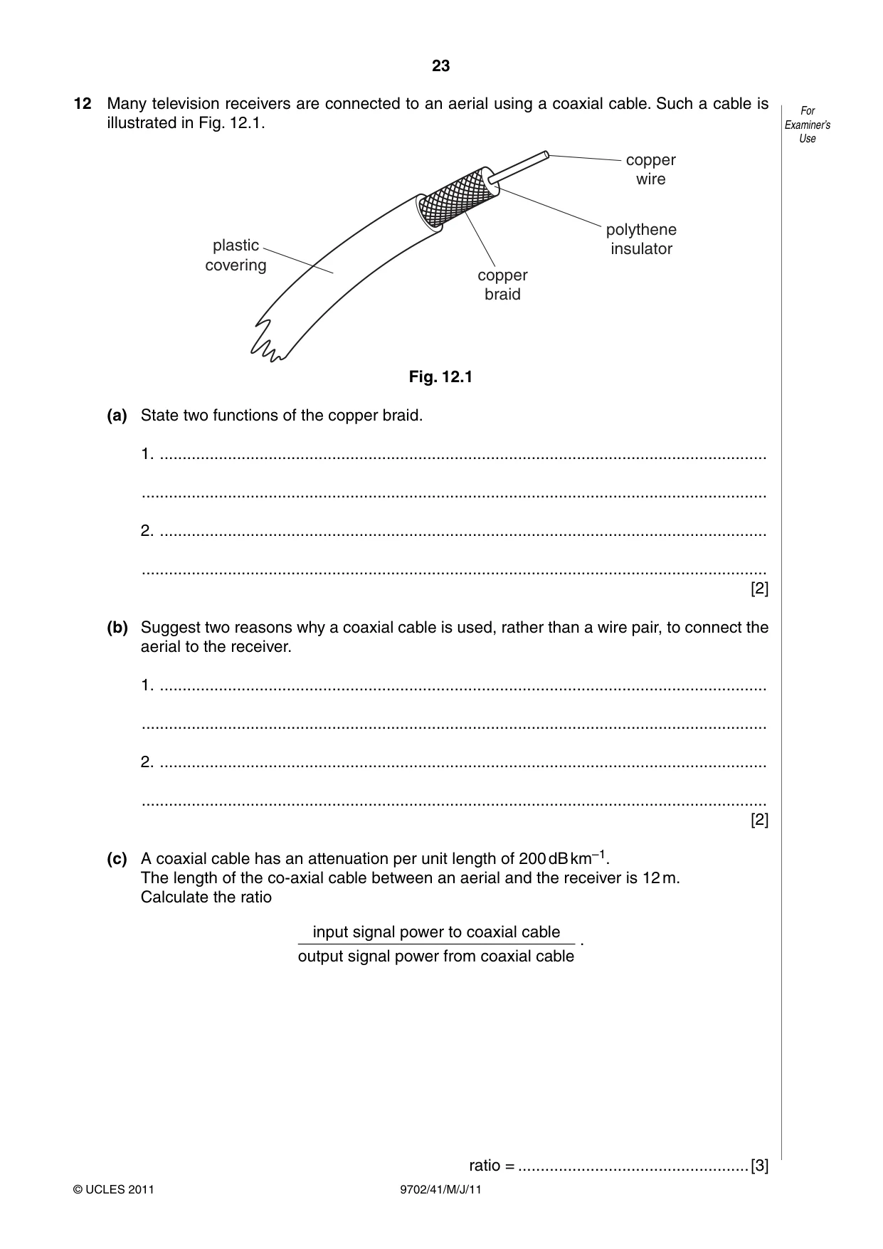
12 Many television receivers are connected to an aerial using a coaxial cable. Such a cable is For illustrated in Fig. 12.1. Examiner’s Use copper wire polythene plastic insulator covering copper braid Fig. 12.1 (a) State two functions of the copper braid. 1. ...................................................................................................................................... .......................................................................................................................................... 2. ...................................................................................................................................... .......................................................................................................................................... [2] (b) Suggest two reasons why a coaxial cable is used, rather than a wire pair, to connect the aerial to the receiver. 1. ...................................................................................................................................... .......................................................................................................................................... 2. ...................................................................................................................................... .......................................................................................................................................... [2] (c) A coaxial cable has an attenuation per unit length of 200 dB km–1. The length of the co-axial cable between an aerial and the receiver is 12 m. Calculate the ratio input signal power to coaxial cable . output signal power from coaxial cable
Mark scheme: 12 (a) e.g. acts as ‘return’ for the signal shields inner core from noise / interference / cross-talk (any two sensible answers, 1 each, max 2) B2 [2] (b) e.g. greater bandwidth less attenuation (per unit length) less noise / interference (any two sensible answers, 1 each, max 2) B2 [2] (c) attenuation is 2.4 dB C1 attenuation = 10 lg(P1 / P2) C1 ratio = 1.7 A1 [3]
What was in this paper
The subtopics covered by these 12 questions, and how many questions each got. Open one in a new tab to see every Cambridge question on it.
1Electric fields and field lines1Electromagnetic induction1Electromagnetic spectrum1Equation of state1Force on a moving charge1Gravitational force between point masses1Photoelectric effect1Practical circuits1Progressive waves1Radioactive decay1Simple harmonic oscillations1What you needed in this session
Cambridge’s own grade thresholds for 2011 May/June, Paper 4 · Variant 1. A higher threshold means an easier paper — the bar moves with how the cohort did.