Cambridge A Level Physics 9702 — 2013 May/June Paper 4 · Variant 1
9702/41/M/J/13 · 12 questions · 100 marks · ≈113 min
The question paper and its mark scheme, free to read here and free to download. This is Cambridge’s own paper, exactly as it was sat.
Question paper24 pages



Mark scheme6 pages
Answers below. Sit the paper first if you are practising.
Questions as text
Q1 · State what is meant by a gravitational field
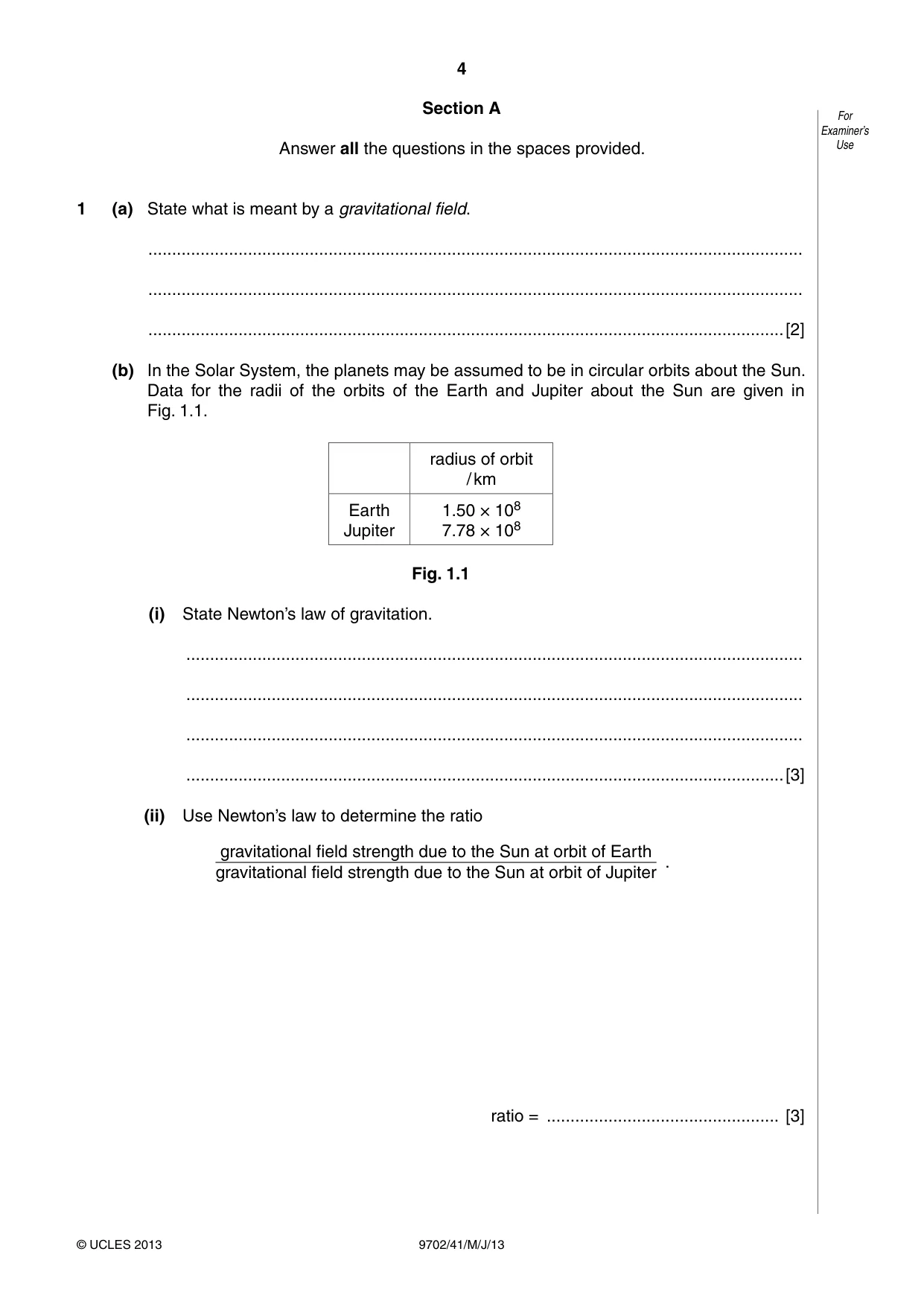
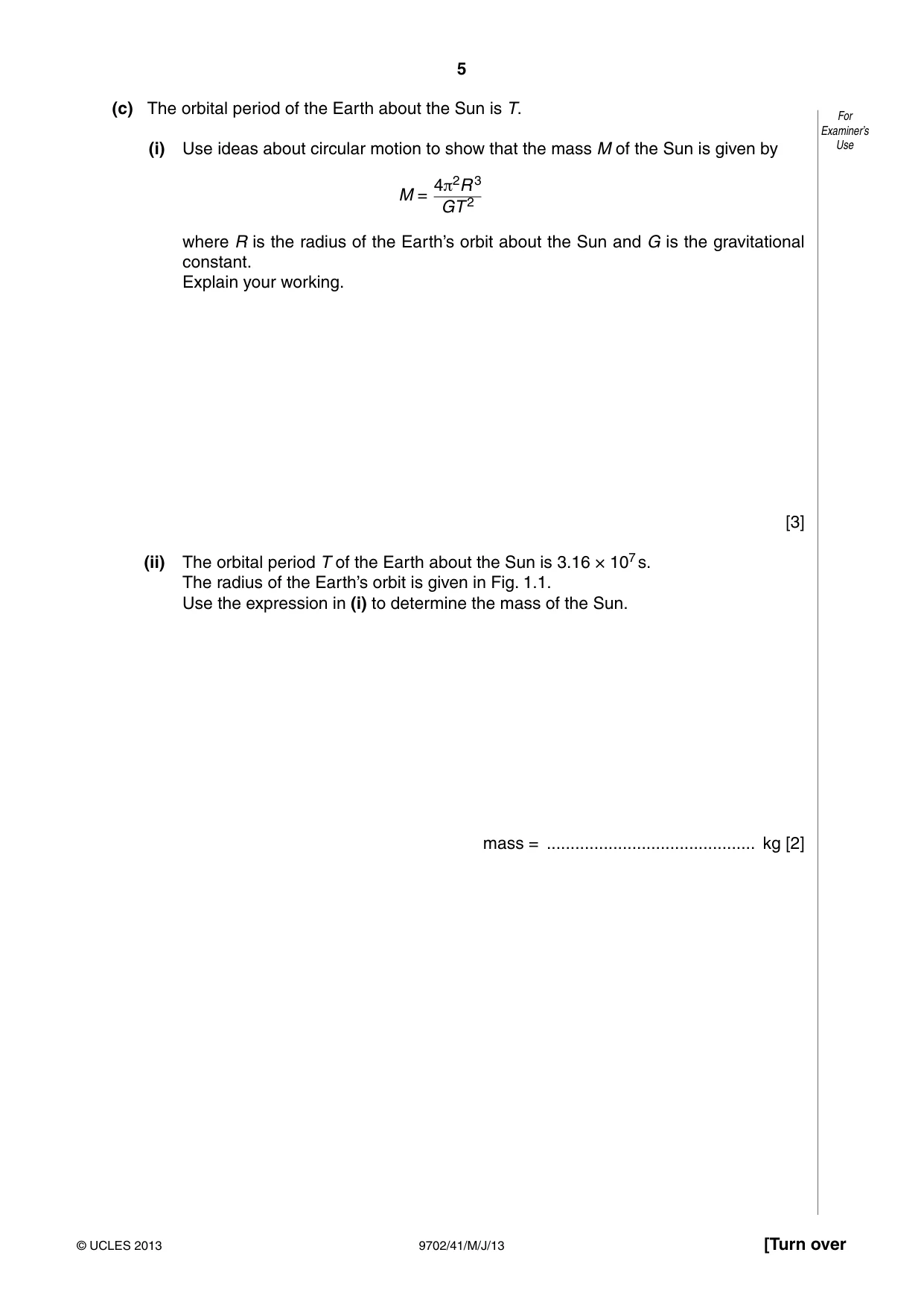
1 (a) State what is meant by a gravitational field. .......................................................................................................................................... .......................................................................................................................................... ......................................................................................................................................[2] (b) In the Solar System, the planets may be assumed to be in circular orbits about the Sun. Data for the radii of the orbits of the Earth and Jupiter about the Sun are given in Fig. 1.1. radius of orbit / km Earth 1.50 × 10⁸ Jupiter 7.78 × 10⁸ Fig. 1.1 (i) State Newton’s law of gravitation. .................................................................................................................................. .................................................................................................................................. .................................................................................................................................. ..............................................................................................................................[3] (ii) Use Newton’s law to determine the ratio gravitational field strength due to the Sun at orbit of Earth . gravitational field strength due to the Sun at orbit of Jupiter ratio = ................................................. [3] (c) The orbital period of the Earth about the Sun is T. For Examiner’s (i) Use ideas about circular motion to show that the mass M of the Sun is given by Use 4π2R 3 M = GT 2 where R is the radius of the Earth’s orbit about the Sun and G is the gravitational constant. Explain your working. [3] (ii) The orbital period T of the Earth about the Sun is 3.16 × 10⁷ s. The radius of the Earth’s orbit is given in Fig. 1.1. Use the expression in (i) to determine the mass of the Sun. mass = ............................................ kg [2]
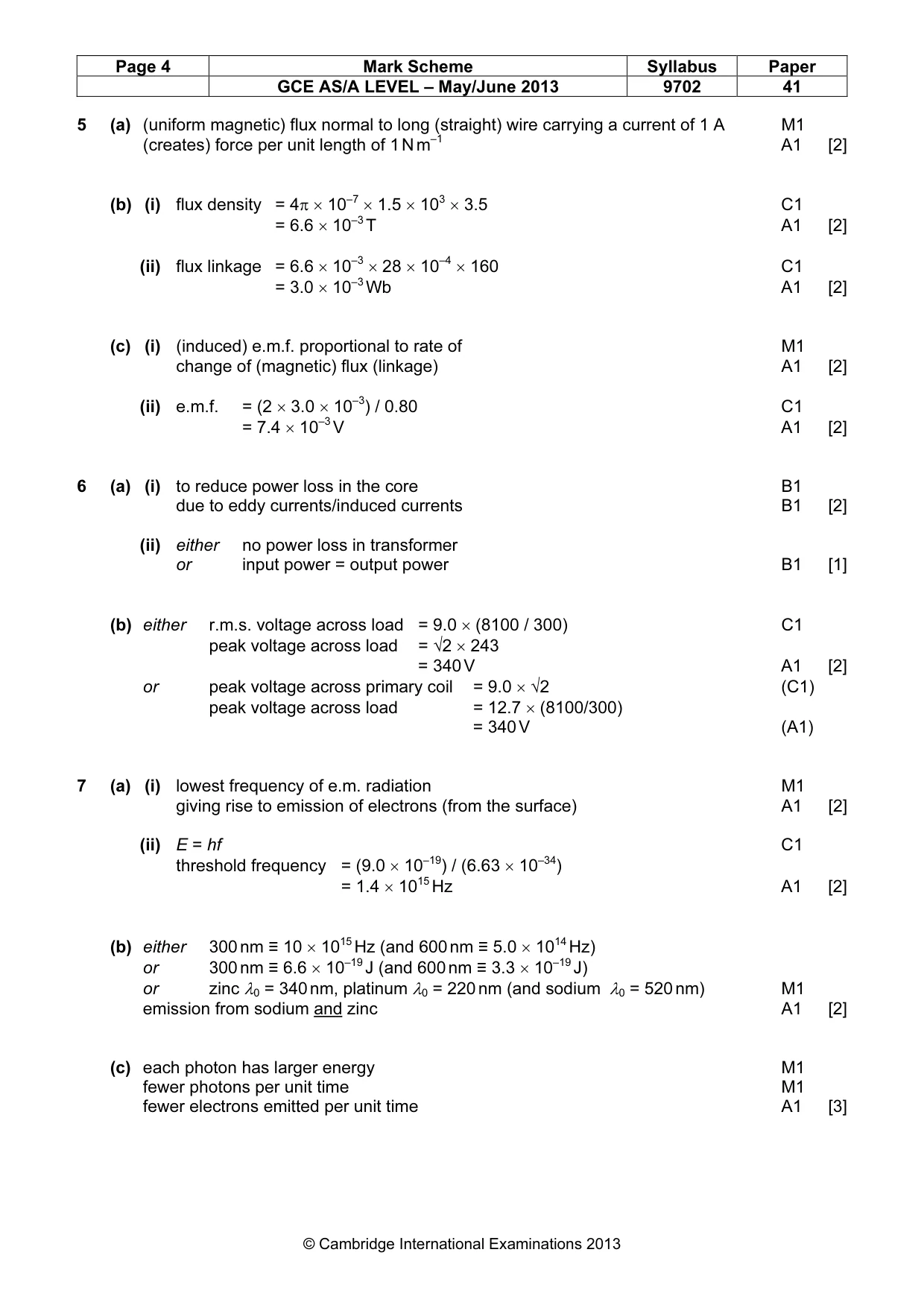
Mark scheme: 1 (a) region of space area / volume B1 where a mass experiences a force B1 [2] (b) (i) force proportional to product of two masses M1 force inversely proportional to the square of their separation M1 either reference to point masses or separation >> ‘size’ of masses A1 [3] (ii) field strength = GM / x2 or field strength ∝ 1 / x2 C1 ratio = (7.78 × 10⁸)2 / (1.5 × 10⁸)2 C1 = 27 A1 [3] (c) (i) either centripetal force = mRω2 and ω = 2π / T or centripetal force = mv2 / R and v = 2πR /T B1 gravitational force provides the centripetal force B1 either GMm / R2 = mRω2 or GMm / R2 = mv2 / R M1 M = 4π2R3 / GT2 A0 [3] (allow working to be given in terms of acceleration) (ii) M = {4π2 × (1.5 × 1011)3} / {6.67 × 10–11 × (3.16 × 107)2} C1 = 2.0 × 1030 kg A1 [2]
Q2 · State what is meant by an ideal gas
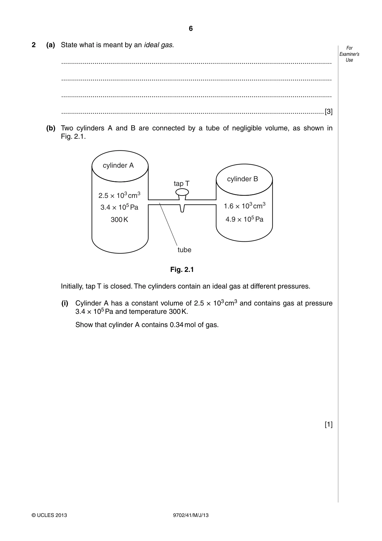
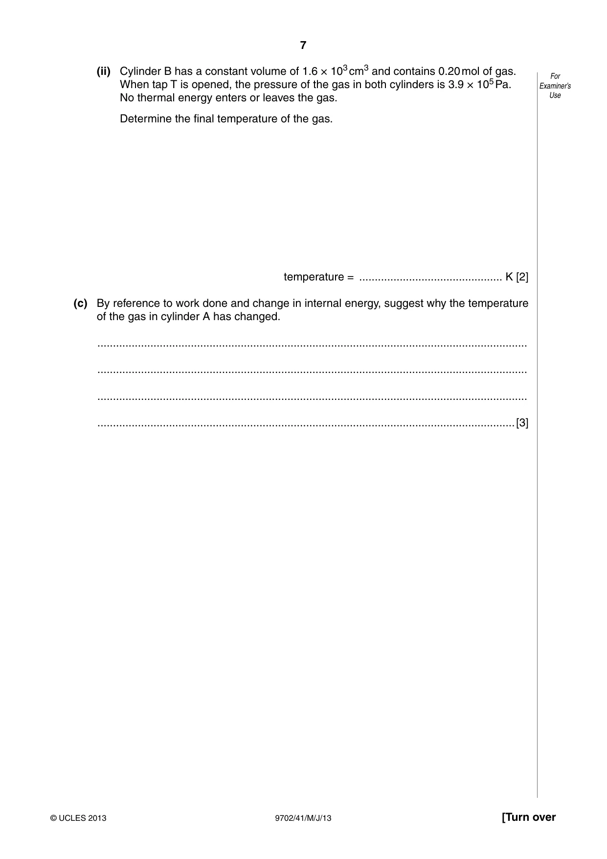
2 (a) State what is meant by an ideal gas. For Examiner’s .......................................................................................................................................... Use .......................................................................................................................................... .......................................................................................................................................... ......................................................................................................................................[3] (b) Two cylinders A and B are connected by a tube of negligible volume, as shown in Fig. 2.1. cylinder A cylinder B tap T 2.5 × 103 cm3 3.4 × 10⁵ Pa 1.6 × 103 cm3 300 K 4.9 × 10⁵ Pa tube Fig. 2.1 Initially, tap T is closed. The cylinders contain an ideal gas at different pressures. (i) Cylinder A has a constant volume of 2.5 × 103 cm3 and contains gas at pressure 3.4 × 10⁵ Pa and temperature 300 K. Show that cylinder A contains 0.34 mol of gas. [1] (ii) Cylinder B has a constant volume of 1.6 × 103 cm3 and contains 0.20 mol of gas. For When tap T is opened, the pressure of the gas in both cylinders is 3.9 × 10⁵ Pa. Examiner’s No thermal energy enters or leaves the gas. Use Determine the final temperature of the gas. temperature = .............................................. K [2] (c) By reference to work done and change in internal energy, suggest why the temperature of the gas in cylinder A has changed. .......................................................................................................................................... .......................................................................................................................................... .......................................................................................................................................... ......................................................................................................................................[3]
Mark scheme: 2 (a) obeys the equation pV = constant × T or pV = nRT M1 p, V and T explained A1 at all values of p, V and T/fixed mass/n is constant A1 [3] (b) (i) 3.4 × 105 × 2.5 × 103 × 10–6 = n × 8.31 × 300 M1 n = 0.34 mol A0 [1] (ii) for total mass/amount of gas 3.9 × 105 × (2.5 + 1.6) × 103 × 10–6 = (0.34 + 0.20) × 8.31 × T C1 T = 360 K A1 [2] (c) when tap opened gas passed (from cylinder B) to cylinder A B1 work done on gas in cylinder A (and no heating) M1 so internal energy and hence temperature increase A1 [3] GCE AS/A LEVEL – May/June 2013 9702 41
Q3 · A ball is held between two fixed points A and B by means of two stretched springs, as…
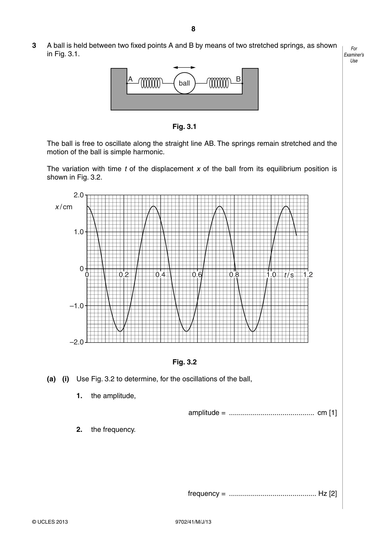
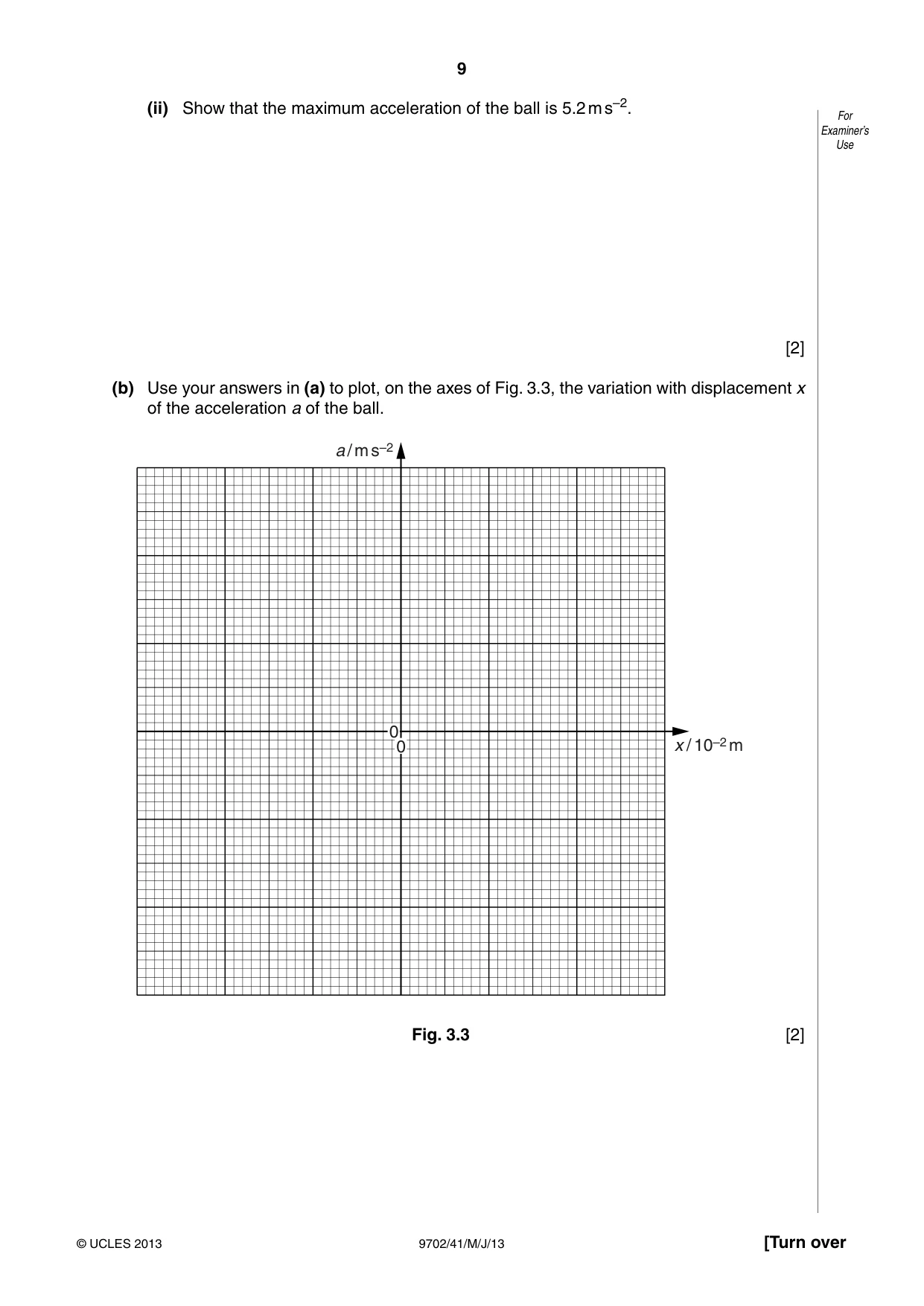
3 A ball is held between two fixed points A and B by means of two stretched springs, as shown For in Fig. 3.1. Examiner’s Use A B ball Fig. 3.1 The ball is free to oscillate along the straight line AB. The springs remain stretched and the motion of the ball is simple harmonic. The variation with time t of the displacement x of the ball from its equilibrium position is shown in Fig. 3.2. 2.0 x / cm 1.0 0 0 0.2 0.4 0.6 0.8 1.0 t / s 1.2 –1.0 –2.0 Fig. 3.2 (a) (i) Use Fig. 3.2 to determine, for the oscillations of the ball, 1. the amplitude, amplitude = ........................................... cm [1] 2. the frequency. frequency = ............................................ Hz [2] (ii) Show that the maximum acceleration of the ball is 5.2 m s–2. For Examiner’s Use [2] (b) Use your answers in (a) to plot, on the axes of Fig. 3.3, the variation with displacement x of the acceleration a of the ball. a / m s–2 0 0 x / 10–2 m Fig. 3.3 [2] (c) Calculate the displacement of the ball at which its kinetic energy is equal to one half of For the maximum kinetic energy. Examiner’s Use displacement = ........................................... cm [3]
Mark scheme: 3 (a) (i) 1. amplitude = 1.7 cm A1 [1] 2. period = 0.36 cm C1 frequency = 1/0.36 frequency = 2.8 Hz A1 [2] (ii) a = (–)ω2x and ω = 2π/T C1 acceleration = (2π/0.36)2 × 1.7 × 10–2 M1 = 5.2 m s–2 A0 [2] (b) graph: straight line, through origin, with negative gradient M1 from (–1.7 × 10⁻², 5.2) to (1.7 × 10⁻², –5.2) A1 [2] (if scale not reasonable, do not allow second mark) (c) either kinetic energy = ½mω2(x02 – x2) or potential energy = ½mω2x2 and potential energy = kinetic energy B1 ½mω2(x0 – x2) = ½ × ½mω2x02 or ½mω2x2 = ½ × ½mω2x02 C1 x02 = 2x2 x = x0 / √2 = 1.7 / √2 = 1.2 cm A1 [3]
Q4 · Define electric potential at a point
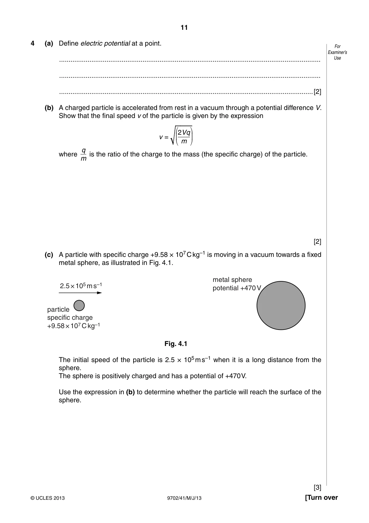
4 (a) Define electric potential at a point. For Examiner’s .......................................................................................................................................... Use .......................................................................................................................................... ......................................................................................................................................[2] (b) A charged particle is accelerated from rest in a vacuum through a potential difference V. Show that the final speed v of the particle is given by the expression ⎛ ⎞ 2Vq v = ⎜ ⎟ ⎝ m ⎠ q where is the ratio of the charge to the mass (the specific charge) of the particle. m [2] (c) A particle with specific charge +9.58 × 10⁷ C kg–1 is moving in a vacuum towards a fixed metal sphere, as illustrated in Fig. 4.1. metal sphere 2.5 × 10⁵ m s–1 potential +470 V particle specific charge +9.58 × 10⁷ C kg–1 Fig. 4.1 The initial speed of the particle is 2.5 × 10⁵ m s–1 when it is a long distance from the sphere. The sphere is positively charged and has a potential of +470 V. Use the expression in (b) to determine whether the particle will reach the surface of the sphere. [3]
Mark scheme: 4 (a) work done moving unit positive charge M1 from infinity (to the point) A1 [2] (b) (gain in) kinetic energy = change in potential energy B1 ½mv2 = qV leading to v = (2Vq/m)½ B1 [2] (c) either (2.5 × 10⁵)2 = 2 × V × 9.58 × 10⁷ C1 V = 330 V M1 this is less than 470 V and so ‘no’ A1 [3] or v = (2 × 470 × 9.58 × 107) (C1) v = 3.0 × 10⁵ m s–1 (M1) this is greater than 2.5 × 10⁵ m s–1 and so ‘no’ (A1) or (2.5 × 10⁵)2 = 2 × 470 × (q/m) (C1) (q/m) = 6.6 × 10⁷ C kg–1 (M1) this is less than 9.58 × 10⁷ C kg–1 and so ‘no’ (A1) GCE AS/A LEVEL – May/June 2013 9702 41
Question 5
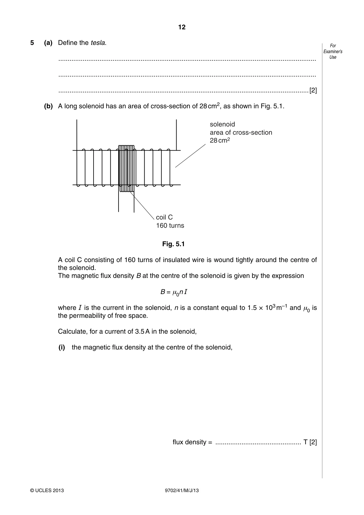
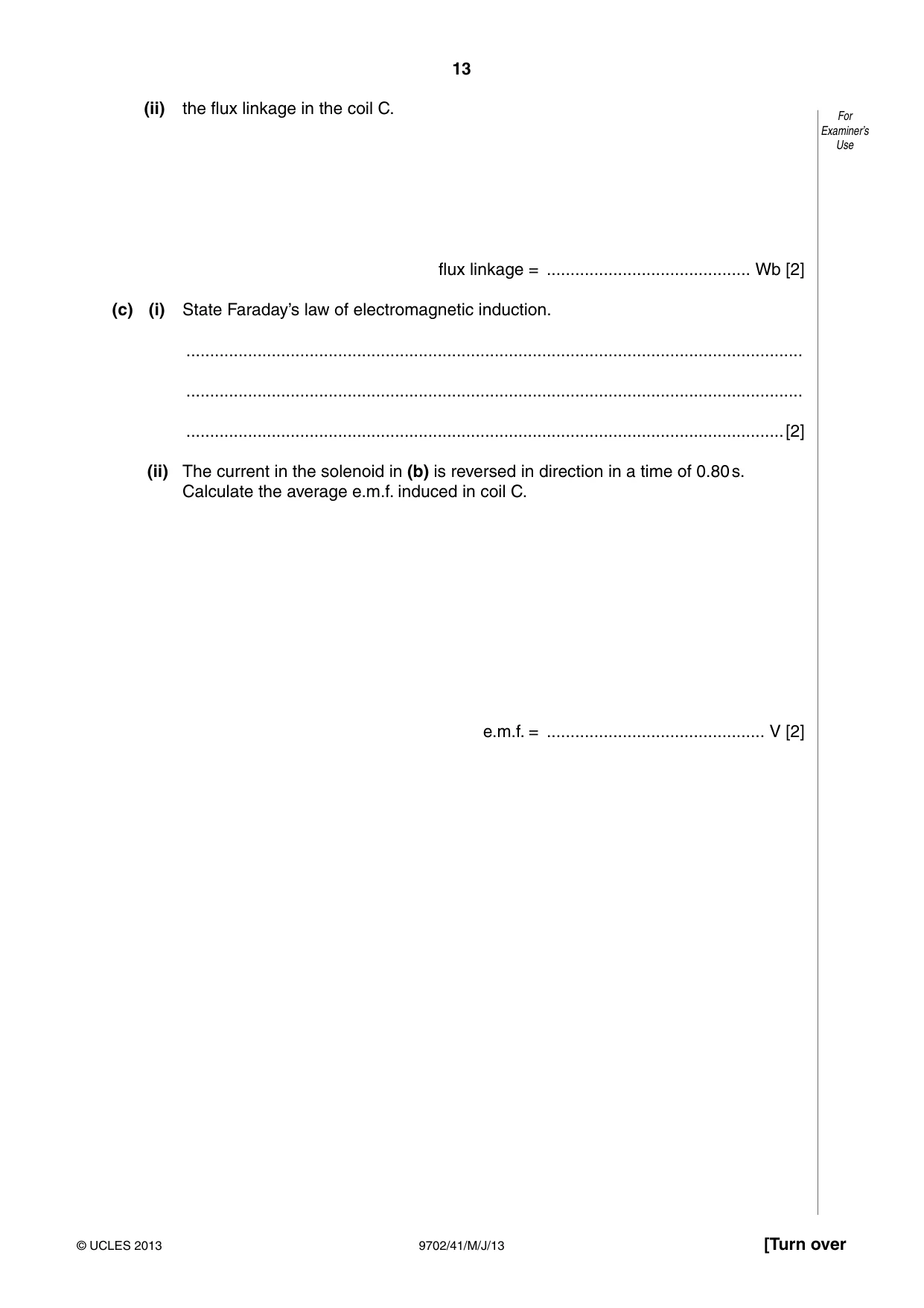
5 (a) Define the tesla. For Examiner’s .......................................................................................................................................... Use .......................................................................................................................................... ......................................................................................................................................[2] (b) A long solenoid has an area of cross-section of 28 cm2, as shown in Fig. 5.1. solenoid area of cross-section 28 cm2 coil C 160 turns Fig. 5.1 A coil C consisting of 160 turns of insulated wire is wound tightly around the centre of the solenoid. The magnetic flux density B at the centre of the solenoid is given by the expression B = μ0n I where I is the current in the solenoid, n is a constant equal to 1.5 × 10³ m–1 and is μ0 the permeability of free space. Calculate, for a current of 3.5 A in the solenoid, (i) the magnetic flux density at the centre of the solenoid, flux density = .............................................. T [2] (ii) the flux linkage in the coil C. For Examiner’s Use flux linkage = ........................................... Wb [2] (c) (i) State Faraday’s law of electromagnetic induction. .................................................................................................................................. .................................................................................................................................. ..............................................................................................................................[2] (ii) The current in the solenoid in (b) is reversed in direction in a time of 0.80 s. Calculate the average e.m.f. induced in coil C. e.m.f. = .............................................. V [2]
Mark scheme: 5 (a) (uniform magnetic) flux normal to long (straight) wire carrying a current of 1 A M1 (creates) force per unit length of 1 N m–1 A1 [2] (b) (i) flux density = 4π × 10–7 × 1.5 × 103 × 3.5 C1 = 6.6 × 10⁻³ T A1 [2] (ii) flux linkage = 6.6 × 10–3 × 28 × 10–4 × 160 C1 = 3.0 × 10⁻³ Wb A1 [2] (c) (i) (induced) e.m.f. proportional to rate of M1 change of (magnetic) flux (linkage) A1 [2] (ii) e.m.f. = (2 × 3.0 × 10–3) / 0.80 C1 = 7.4 × 10⁻³ V A1 [2]
Q6 · A simple transformer is illustrated in Fig
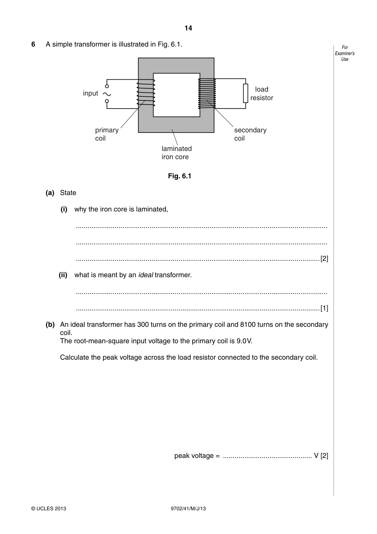
6 A simple transformer is illustrated in Fig. 6.1. For Examiner’s Use load input resistor primary secondary coil coil laminated iron core Fig. 6.1 (a) State (i) why the iron core is laminated, .................................................................................................................................. .................................................................................................................................. ..............................................................................................................................[2] (ii) what is meant by an ideal transformer. .................................................................................................................................. ..............................................................................................................................[1] (b) An ideal transformer has 300 turns on the primary coil and 8100 turns on the secondary coil. The root-mean-square input voltage to the primary coil is 9.0 V. Calculate the peak voltage across the load resistor connected to the secondary coil. peak voltage = .............................................. V [2]
Mark scheme: 6 (a) (i) to reduce power loss in the core B1 due to eddy currents/induced currents B1 [2] (ii) either no power loss in transformer or input power = output power B1 [1] (b) either r.m.s. voltage across load = 9.0 × (8100 / 300) C1 peak voltage across load = √2 × 243 = 340 V A1 [2] or peak voltage across primary coil = 9.0 × √2 (C1) peak voltage across load = 12.7 × (8100/300) = 340 V (A1)
Q7 · Some data for the work function energy Φ and the threshold frequency f0 of some metal For…
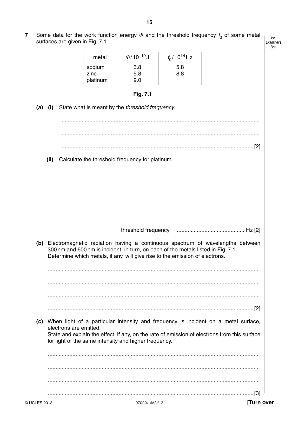
7 Some data for the work function energy Φ and the threshold frequency f0 of some metal For surfaces are given in Fig. 7.1. Examiner’s Use metal Φ / 10–19 J f0 / 1014 Hz sodium 3.8 5.8 zinc 5.8 8.8 platinum 9.0 Fig. 7.1 (a) (i) State what is meant by the threshold frequency. .................................................................................................................................. .................................................................................................................................. ..............................................................................................................................[2] (ii) Calculate the threshold frequency for platinum. threshold frequency = ............................................ Hz [2] (b) Electromagnetic radiation having a continuous spectrum of wavelengths between 300 nm and 600 nm is incident, in turn, on each of the metals listed in Fig. 7.1. Determine which metals, if any, will give rise to the emission of electrons. .......................................................................................................................................... .......................................................................................................................................... .......................................................................................................................................... ......................................................................................................................................[2] (c) When light of a particular intensity and frequency is incident on a metal surface, electrons are emitted. State and explain the effect, if any, on the rate of emission of electrons from this surface for light of the same intensity and higher frequency. .......................................................................................................................................... .......................................................................................................................................... .......................................................................................................................................... ......................................................................................................................................[3]
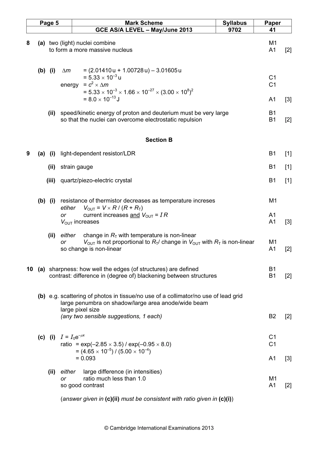
Mark scheme: 7 (a) (i) lowest frequency of e.m. radiation M1 giving rise to emission of electrons (from the surface) A1 [2] (ii) E = hf C1 threshold frequency = (9.0 × 10⁻¹⁹) / (6.63 × 10⁻³⁴) = 1.4 × 10¹⁵ Hz A1 [2] (b) either 300 nm ≡ 10 × 1015 Hz (and 600 nm ≡ 5.0 × 10¹⁴ Hz) or 300 nm ≡ 6.6 × 10⁻¹⁹ J (and 600 nm ≡ 3.3 × 10⁻¹⁹ J) or zinc λ0 = 340 nm, platinum λ0 = 220 nm (and sodium λ0 = 520 nm) M1 emission from sodium and zinc A1 [2] (c) each photon has larger energy M1 fewer photons per unit time M1 fewer electrons emitted per unit time A1 [3] GCE AS/A LEVEL – May/June 2013 9702 41
Q8 · State what is meant by a nuclear fusion reaction
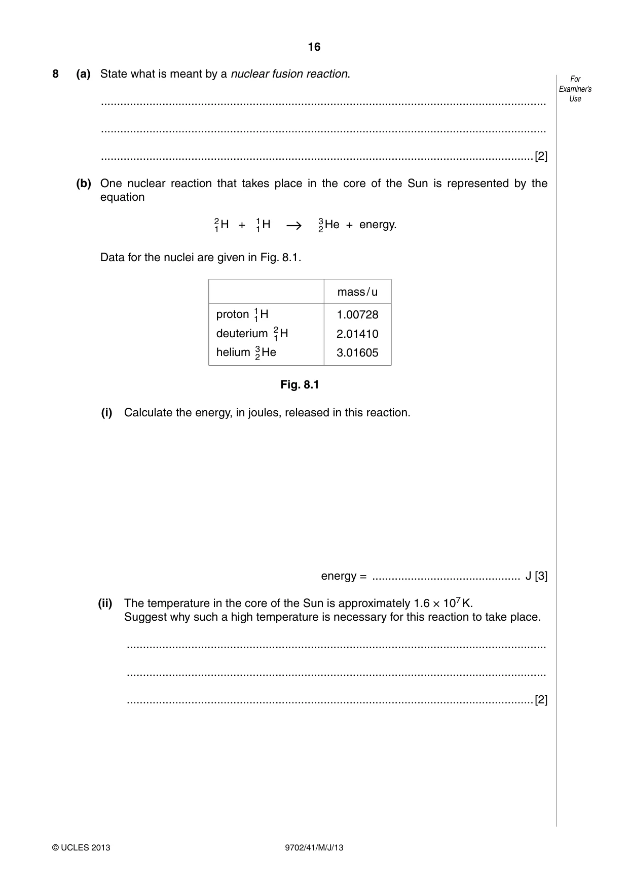
8 (a) State what is meant by a nuclear fusion reaction. For Examiner’s .......................................................................................................................................... Use .......................................................................................................................................... ......................................................................................................................................[2] (b) One nuclear reaction that takes place in the core of the Sun is represented by the equation 2 H + 1 H 3 He + energy. 1 1 2 Data for the nuclei are given in Fig. 8.1. mass / u proton 1 H 1.00728 1 deuterium 2 H 2.01410 1 helium 3 He 3.01605 2 Fig. 8.1 (i) Calculate the energy, in joules, released in this reaction. energy = .............................................. J [3] (ii) The temperature in the core of the Sun is approximately 1.6 × 10⁷ K. Suggest why such a high temperature is necessary for this reaction to take place. .................................................................................................................................. .................................................................................................................................. ..............................................................................................................................[2]
Mark scheme: 8 (a) two (light) nuclei combine M1 to form a more massive nucleus A1 [2] (b) (i) ∆m = (2.01410 u + 1.00728 u) – 3.01605 u = 5.33 × 10⁻³ u C1 energy = c2 × ∆m C1 = 5.33 × 10–3 × 1.66 × 10–27 × (3.00 × 108)2 = 8.0 × 10⁻¹³ J A1 [3] (ii) speed/kinetic energy of proton and deuterium must be very large B1 so that the nuclei can overcome electrostatic repulsion B1 [2] Section B
Q9 · Suggest electrical sensing devices, one in each case, that may be used to monitor changes…
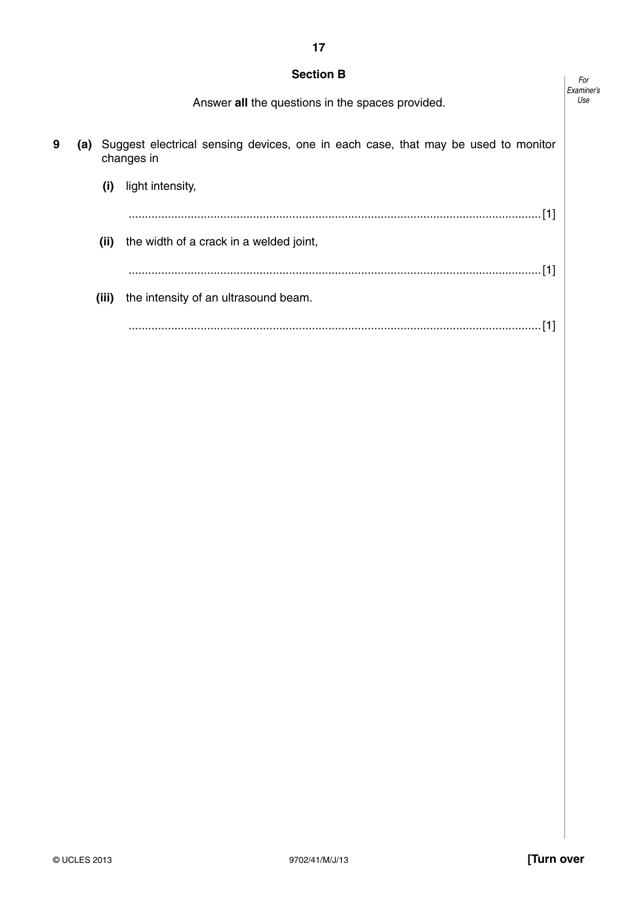
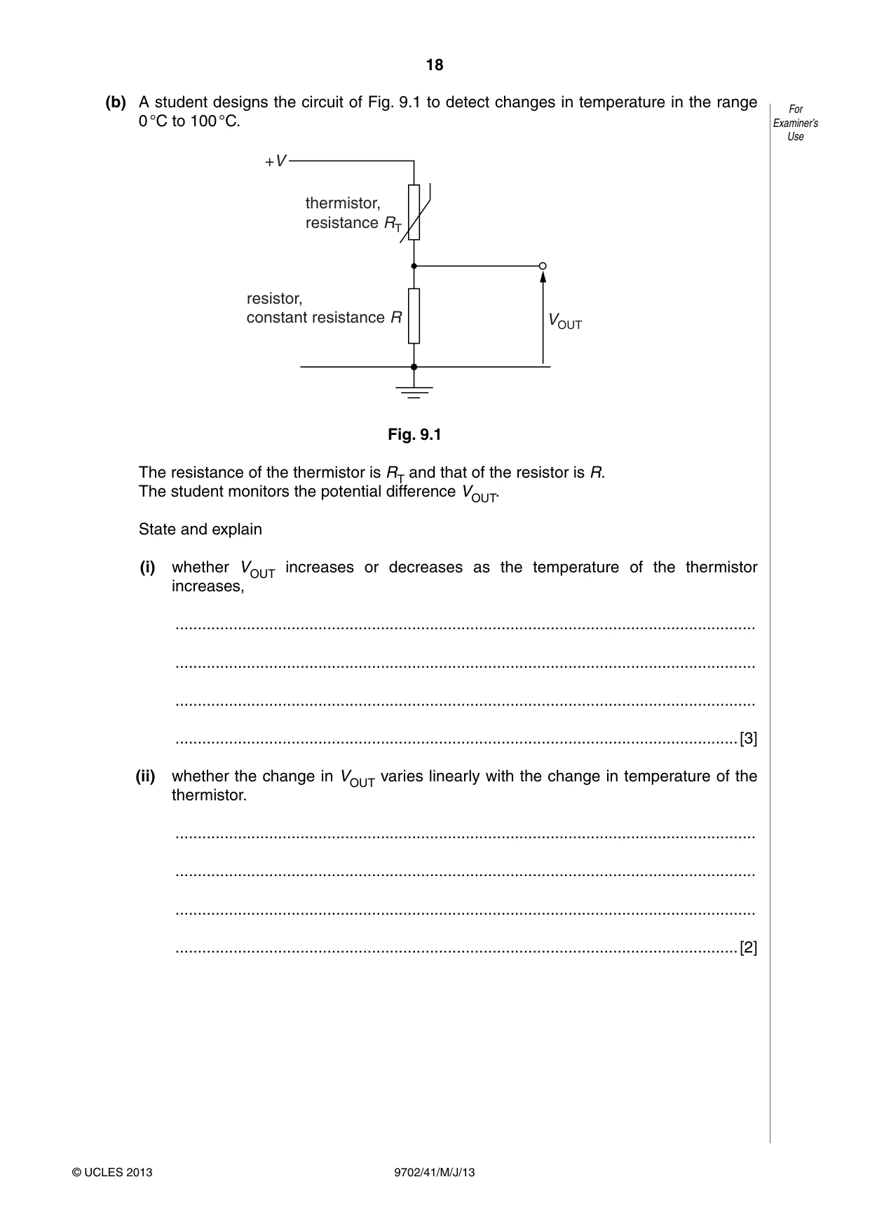
9 (a) Suggest electrical sensing devices, one in each case, that may be used to monitor changes in (i) light intensity, ..............................................................................................................................[1] (ii) the width of a crack in a welded joint, ..............................................................................................................................[1] (iii) the intensity of an ultrasound beam. ..............................................................................................................................[1] (b) A student designs the circuit of Fig. 9.1 to detect changes in temperature in the range For 0 °C to 100 °C. Examiner’s Use +V thermistor, resistance RT resistor, constant resistance R VOUT Fig. 9.1 The resistance of the thermistor is RT and that of the resistor is R. The student monitors the potential difference VOUT. State and explain (i) whether VOUT increases or decreases as the temperature of the thermistor increases, .................................................................................................................................. .................................................................................................................................. .................................................................................................................................. ..............................................................................................................................[3] (ii) whether the change in VOUT varies linearly with the change in temperature of the thermistor. .................................................................................................................................. .................................................................................................................................. .................................................................................................................................. ..............................................................................................................................[2]
Mark scheme: 9 (a) (i) light-dependent resistor/LDR B1 [1] (ii) strain gauge B1 [1] (iii) quartz/piezo-electric crystal B1 [1] (b) (i) resistance of thermistor decreases as temperature increses M1 etiher VOUT = V × R / (R + RT) or current increases and VOUT = I R A1 VOUT increases A1 [3] (ii) either change in RT with temperature is non-linear or VOUT is not proportional to RT/ change in VOUT with RT is non-linear M1 so change is non-linear A1 [2]
Q10 · Distinguish between sharpness and contrast in X-ray imaging
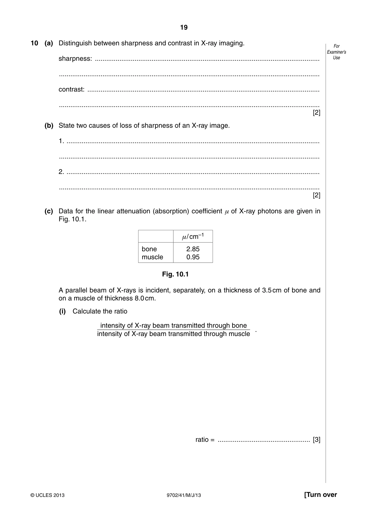
10 (a) Distinguish between sharpness and contrast in X-ray imaging. For Examiner’s sharpness: ....................................................................................................................... Use .......................................................................................................................................... contrast: ........................................................................................................................... .......................................................................................................................................... [2] (b) State two causes of loss of sharpness of an X-ray image. 1. ...................................................................................................................................... .......................................................................................................................................... 2. ...................................................................................................................................... .......................................................................................................................................... [2] (c) Data for the linear attenuation (absorption) coefficient μ of X-ray photons are given in Fig. 10.1. μ/ cm–1 bone 2.85 muscle 0.95 Fig. 10.1 A parallel beam of X-rays is incident, separately, on a thickness of 3.5 cm of bone and on a muscle of thickness 8.0 cm. (i) Calculate the ratio intensity of X-ray beam transmitted through bone . intensity of X-ray beam transmitted through muscle ratio = ................................................. [3] (ii) Use your answer in (i) to suggest whether an X-ray image of the bone and muscle For would show good or poor contrast. Examiner’s Use .................................................................................................................................. .................................................................................................................................. ..............................................................................................................................[2]
Mark scheme: 10 (a) sharpness: how well the edges (of structures) are defined B1 contrast: difference in (degree of) blackening between structures B1 [2] (b) e.g. scattering of photos in tissue/no use of a collimator/no use of lead grid large penumbra on shadow/large area anode/wide beam large pixel size (any two sensible suggestions, 1 each) B2 [2] (c) (i) I = I0e–µx C1 ratio = exp(–2.85 × 3.5) / exp(–0.95 × 8.0) C1 = (4.65 × 10⁻⁵) / (5.00 × 10⁻⁴) = 0.093 A1 [3] (ii) either large difference (in intensities) or ratio much less than 1.0 M1 so good contrast A1 [2] (answer given in (c)(ii) must be consistent with ratio given in (c)(i)) GCE AS/A LEVEL – May/June 2013 9702 41
Q11 · A radio station emits an amplitude-modulated wave for the transmission of music
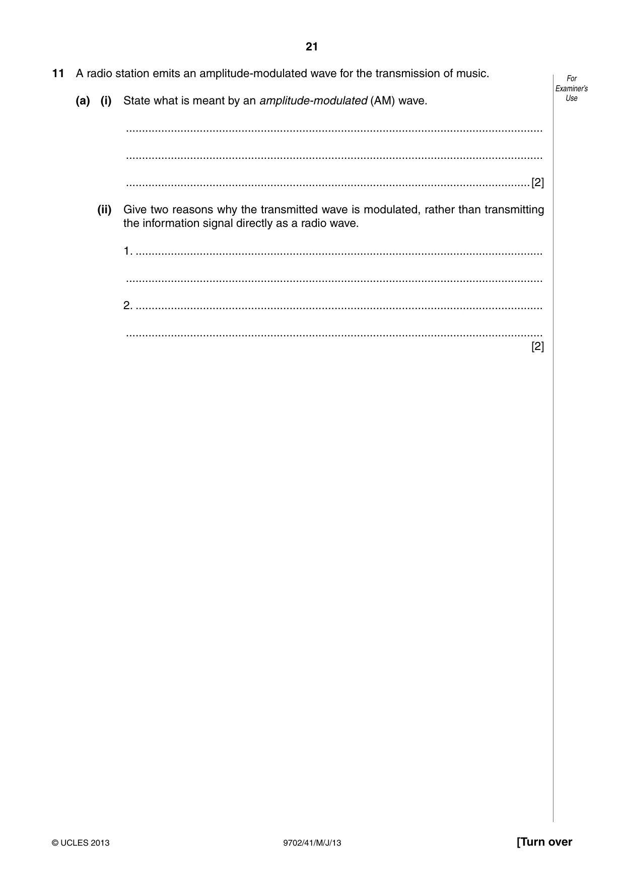
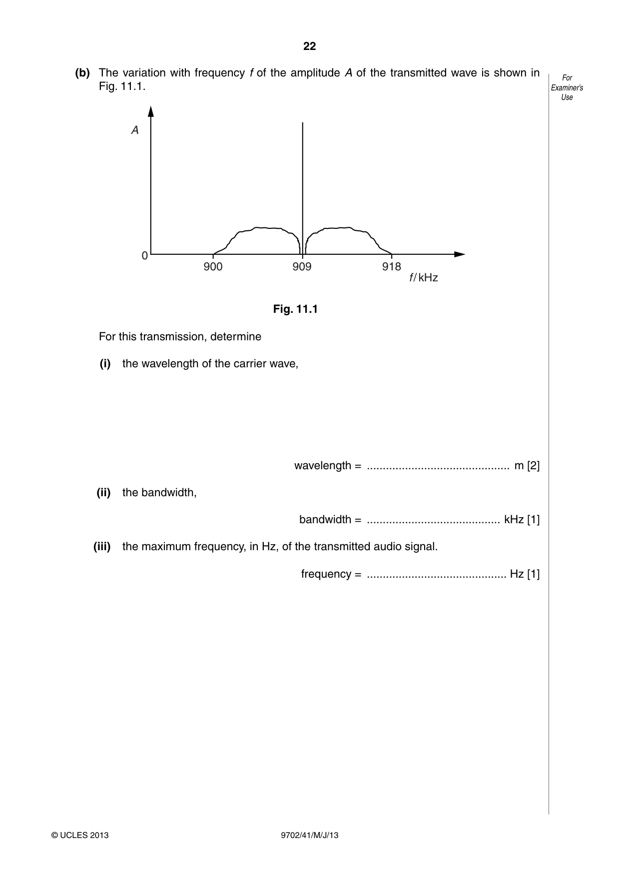
11 A radio station emits an amplitude-modulated wave for the transmission of music. For Examiner’s (a) (i) State what is meant by an amplitude-modulated (AM) wave. Use .................................................................................................................................. .................................................................................................................................. ..............................................................................................................................[2] (ii) Give two reasons why the transmitted wave is modulated, rather than transmitting the information signal directly as a radio wave. 1. ............................................................................................................................... .................................................................................................................................. 2. ............................................................................................................................... .................................................................................................................................. [2] (b) The variation with frequency f of the amplitude A of the transmitted wave is shown in For Fig. 11.1. Examiner’s Use A 0 900 909 918 f / kHz Fig. 11.1 For this transmission, determine (i) the wavelength of the carrier wave, wavelength = ............................................. m [2] (ii) the bandwidth, bandwidth = .......................................... kHz [1] (iii) the maximum frequency, in Hz, of the transmitted audio signal. frequency = ............................................ Hz [1]
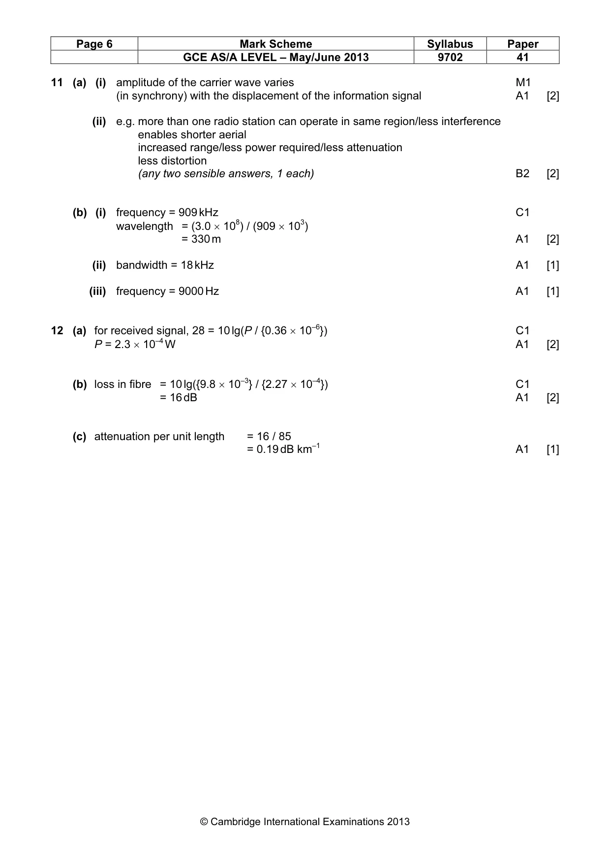
Mark scheme: 11 (a) (i) amplitude of the carrier wave varies M1 (in synchrony) with the displacement of the information signal A1 [2] (ii) e.g. more than one radio station can operate in same region/less interference enables shorter aerial increased range/less power required/less attenuation less distortion (any two sensible answers, 1 each) B2 [2] (b) (i) frequency = 909 kHz C1 wavelength = (3.0 × 10⁸) / (909 × 103) = 330 m A1 [2] (ii) bandwidth = 18 kHz A1 [1] (iii) frequency = 9000 Hz A1 [1]
Q12 · An optic fibre is used for the transmission of digital telephone signals
12 An optic fibre is used for the transmission of digital telephone signals. The power input to the For optic fibre is 9.8 mW. The effective noise level in the receiver circuit is 0.36 μW, as illustrated Examiner’s in Fig. 12.1. Use 85 km receiver input circuit, 9.8 mW circuit optic fibre noise 0.36 +W Fig. 12.1 The signal-to-noise ratio at the receiver must not fall below 28 dB. For this transmission without any repeater amplifiers, the maximum length of the optic fibre is 85 km. (a) Calculate the minimum input signal power to the receiver. power = ............................................. W [2] (b) Use your answer in (a) to calculate the attenuation in the fibre. attenuation = ............................................ dB [2] (c) Determine the attenuation per unit length of the fibre.
Mark scheme: 12 (a) for received signal, 28 = 10 lg(P / {0.36 × 10⁻⁶}) C1 P = 2.3 × 10⁻⁴ W A1 [2] (b) loss in fibre = 10 lg({9.8 × 10⁻³} / {2.27 × 10⁻⁴}) C1 = 16 dB A1 [2] (c) attenuation per unit length = 16 / 85 = 0.19 dB km–1 A1 [1]
What was in this paper
The subtopics covered by these 12 questions, and how many questions each got. Open one in a new tab to see every Cambridge question on it.
1Electromagnetic induction1Electromagnetic spectrum1Gravitational field of a point mass1Kinetic theory of gases1Magnetic fields due to currents1Mass defect and nuclear binding energy1Photoelectric effect1Physical quantities1Potential difference and power1Production and use of X-rays1Simple harmonic oscillations1What you needed in this session
Cambridge’s own grade thresholds for 2013 May/June, Paper 4 · Variant 1. A higher threshold means an easier paper — the bar moves with how the cohort did.