Cambridge A Level Physics 9702 — 2013 May/June Paper 4 · Variant 2
9702/42/M/J/13 · 12 questions · 100 marks · ≈113 min
The question paper and its mark scheme, free to read here and free to download. This is Cambridge’s own paper, exactly as it was sat.
Question paper24 pages
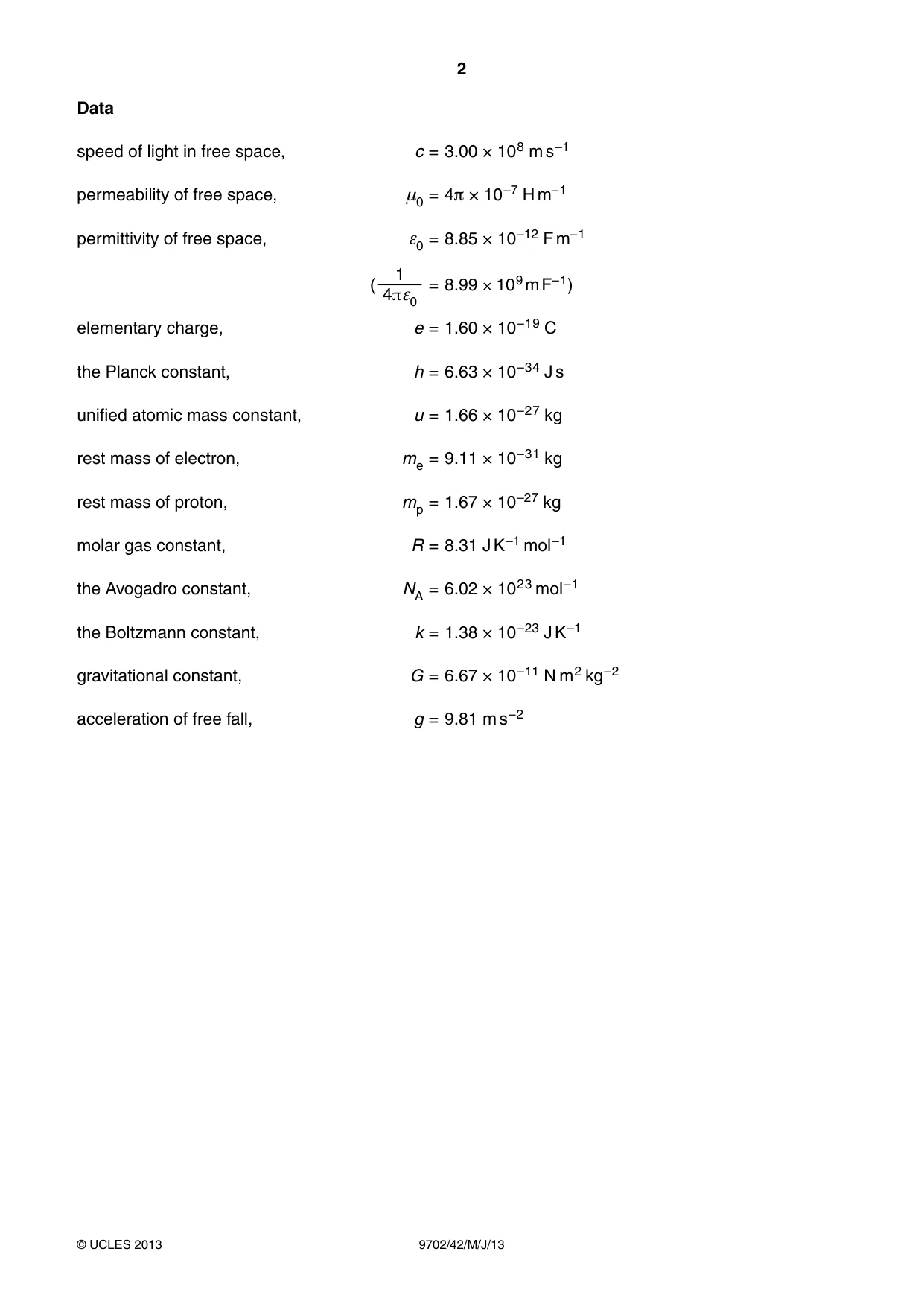
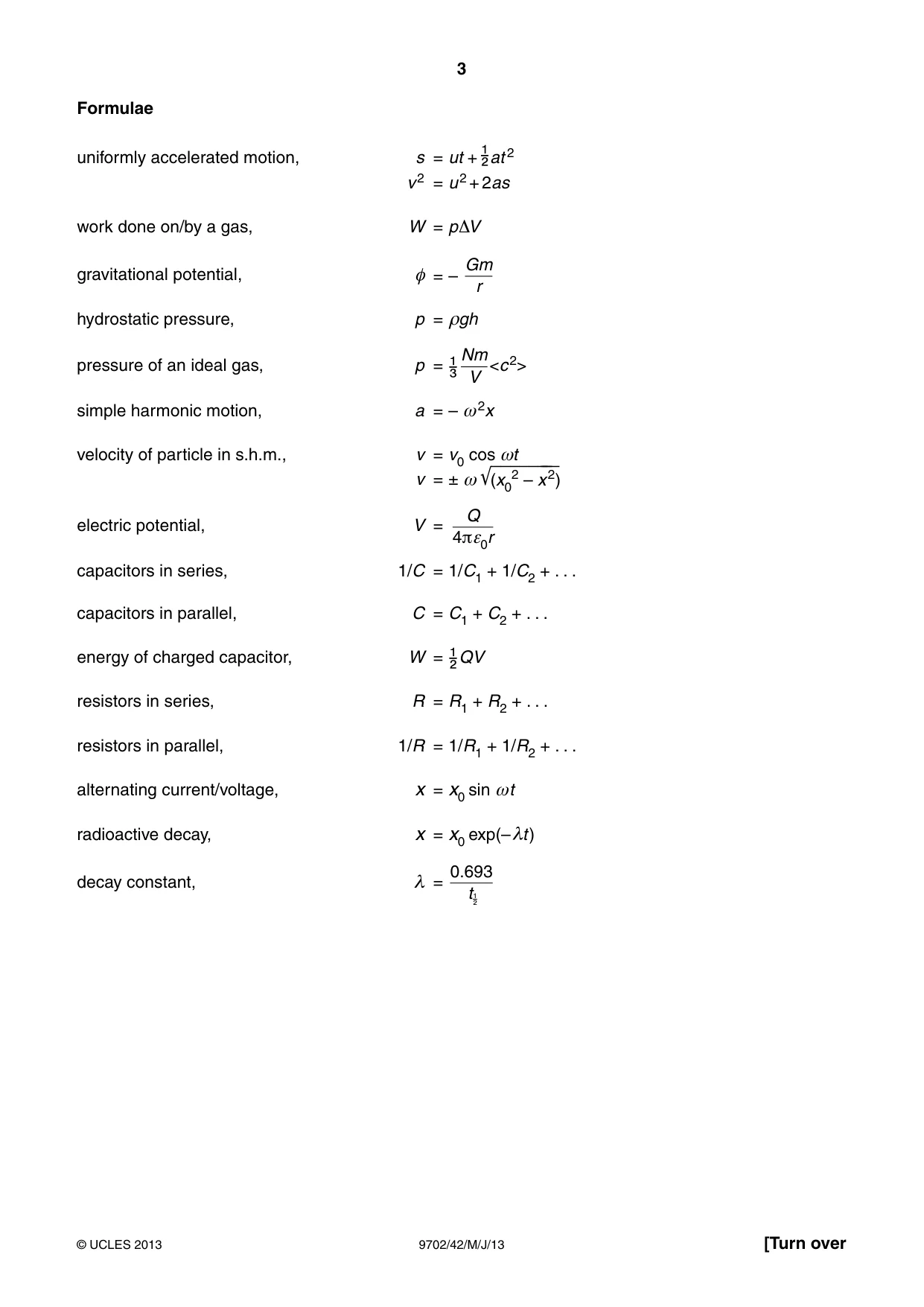

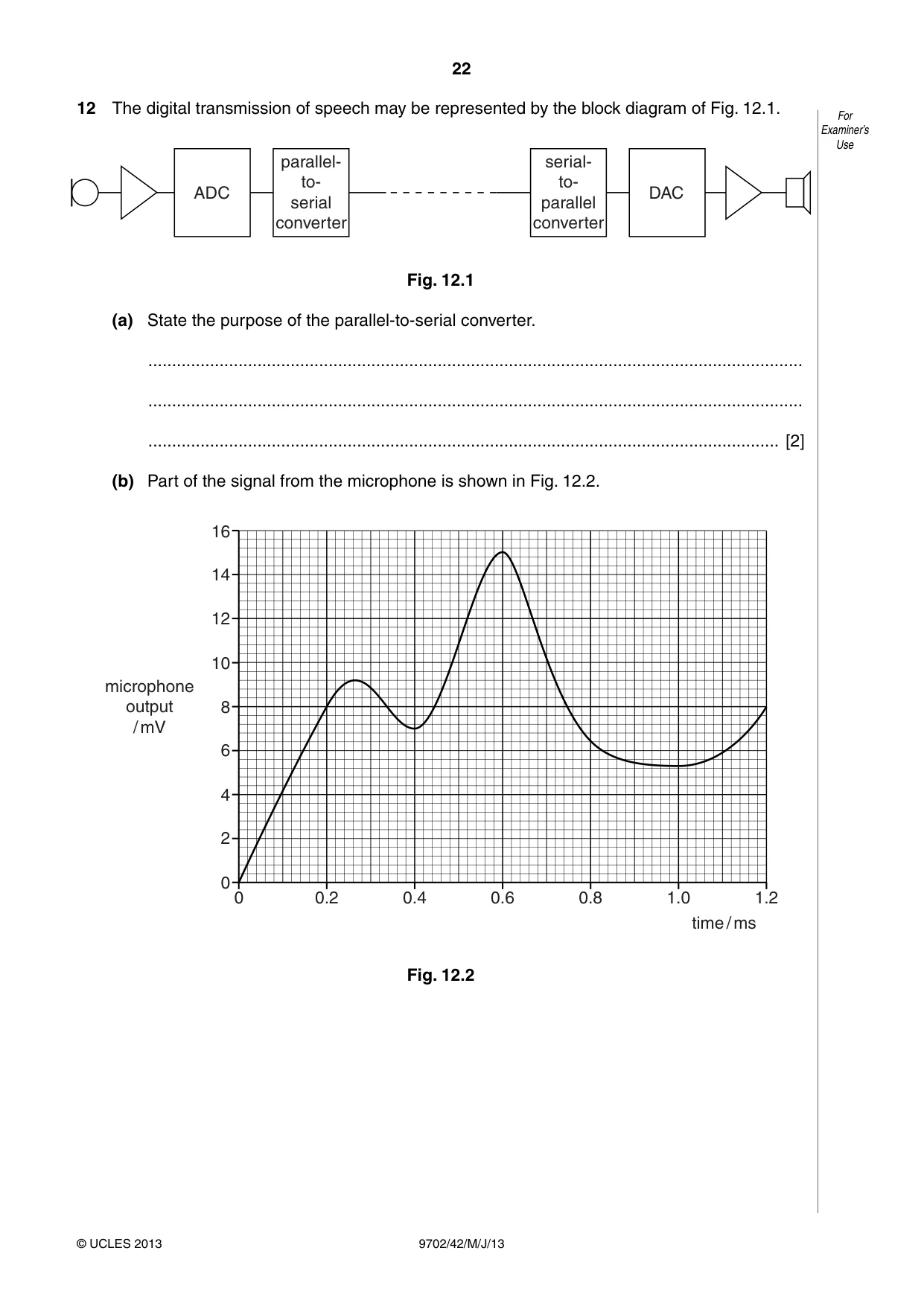
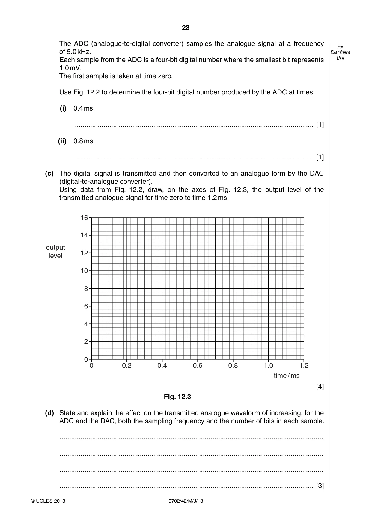

Mark scheme7 pages
Answers below. Sit the paper first if you are practising.
Questions as text
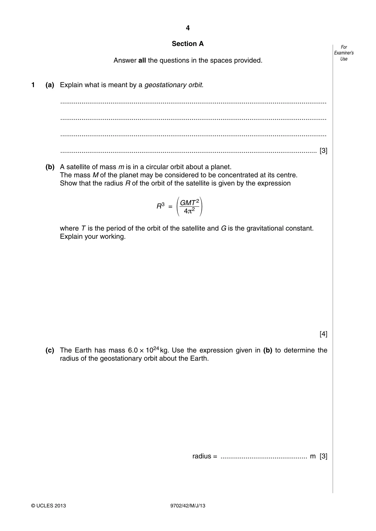
Q1 · Explain what is meant by a geostationary orbit
1 (a) Explain what is meant by a geostationary orbit. .......................................................................................................................................... .......................................................................................................................................... .......................................................................................................................................... ..................................................................................................................................... [3] (b) A satellite of mass m is in a circular orbit about a planet. The mass M of the planet may be considered to be concentrated at its centre. Show that the radius R of the orbit of the satellite is given by the expression GMT 2 R3 = 4π2 where T is the period of the orbit of the satellite and G is the gravitational constant. Explain your working. [4] (c) The Earth has mass 6.0 × 1024 kg. Use the expression given in (b) to determine the radius of the geostationary orbit about the Earth. radius = ............................................. m [3]
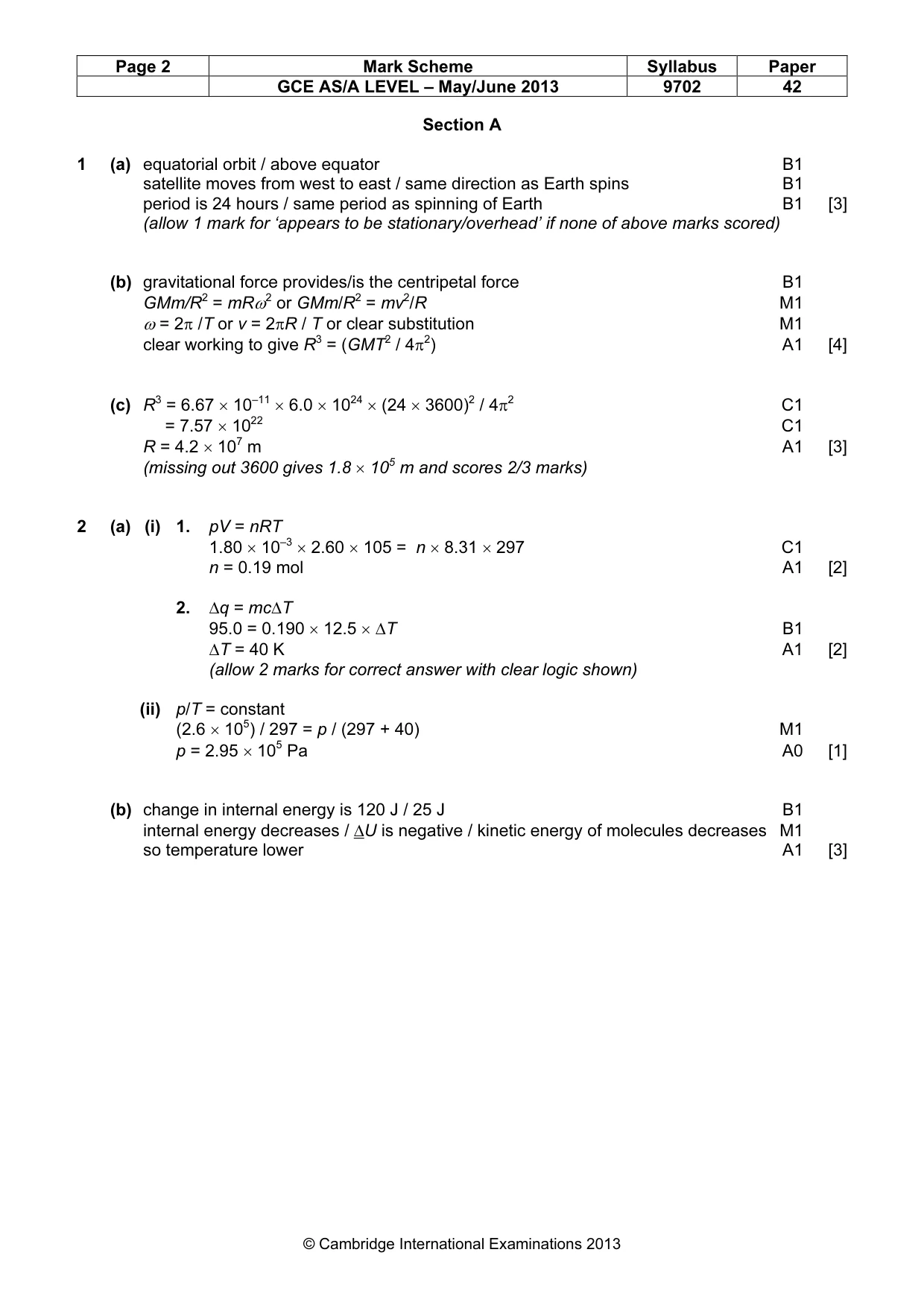
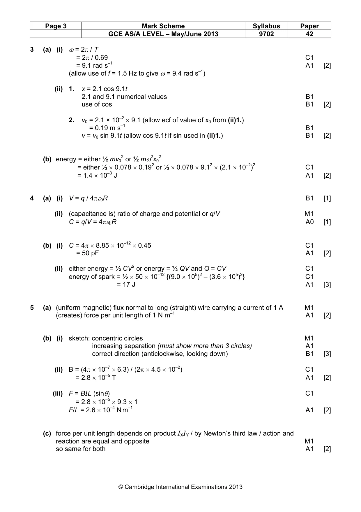
Mark scheme: 1 (a) equatorial orbit / above equator B1 satellite moves from west to east / same direction as Earth spins B1 period is 24 hours / same period as spinning of Earth B1 [3] (allow 1 mark for ‘appears to be stationary/overhead’ if none of above marks scored) (b) gravitational force provides/is the centripetal force B1 GMm/R2 = mRω2 or GMm/R2 = mv2/R M1 ω = 2π /T or v = 2πR / T or clear substitution M1 clear working to give R3 = (GMT2 / 4π2) A1 [4] (c) R3 = 6.67 × 10–11 × 6.0 × 1024 × (24 × 3600)2 / 4π2 C1 = 7.57 × 10²² C1 R = 4.2 × 10⁷ m A1 [3] (missing out 3600 gives 1.8 × 10⁵ m and scores 2/3 marks)
Q2 · The volume of an ideal gas in a cylinder is 1.80 × 10⁻³ m3 at a pressure of 2.60 × 10⁵ Pa…
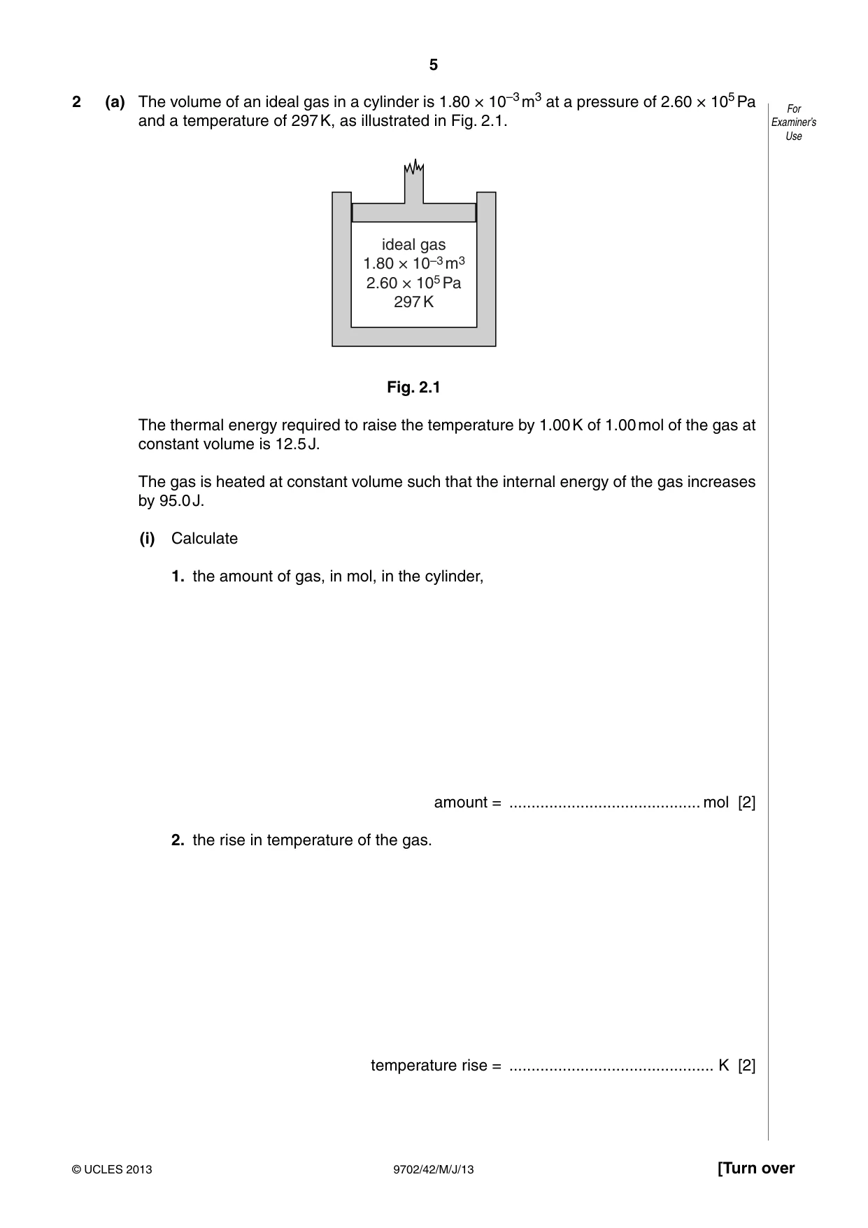
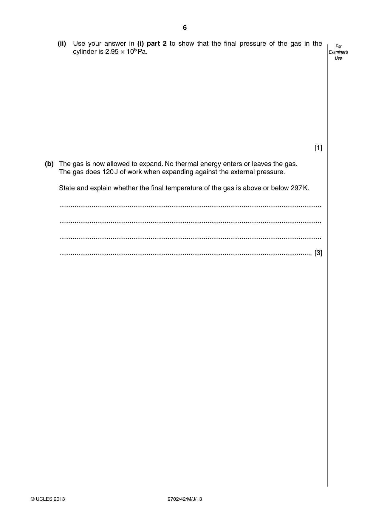
2 (a) The volume of an ideal gas in a cylinder is 1.80 × 10⁻³ m3 at a pressure of 2.60 × 10⁵ Pa For and a temperature of 297 K, as illustrated in Fig. 2.1. Examiner’s Use ideal gas 1.80 × 10⁻³ m3 2.60 × 10⁵ Pa 297 K Fig. 2.1 The thermal energy required to raise the temperature by 1.00 K of 1.00 mol of the gas at constant volume is 12.5 J. The gas is heated at constant volume such that the internal energy of the gas increases by 95.0 J. (i) Calculate 1. the amount of gas, in mol, in the cylinder, amount = ........................................... mol [2] 2. the rise in temperature of the gas. temperature rise = .............................................. K [2] (ii) Use your answer in (i) part 2 to show that the final pressure of the gas in the For cylinder is 2.95 × 10⁵ Pa. Examiner’s Use [1] (b) The gas is now allowed to expand. No thermal energy enters or leaves the gas. The gas does 120 J of work when expanding against the external pressure. State and explain whether the final temperature of the gas is above or below 297 K. .......................................................................................................................................... .......................................................................................................................................... .......................................................................................................................................... ..................................................................................................................................... [3]
Mark scheme: 2 (a) (i) 1. pV = nRT 1.80 × 10–3 × 2.60 × 105 = n × 8.31 × 297 C1 n = 0.19 mol A1 [2] 2. ∆q = mc∆T 95.0 = 0.190 × 12.5 × ∆T B1 ∆T = 40 K A1 [2] (allow 2 marks for correct answer with clear logic shown) (ii) p/T = constant (2.6 × 10⁵) / 297 = p / (297 + 40) M1 p = 2.95 × 10⁵ Pa A0 [1] (b) change in internal energy is 120 J / 25 J B1 internal energy decreases / ∆U is negative / kinetic energy of molecules decreases M1 so temperature lower A1 [3] GCE AS/A LEVEL – May/June 2013 9702 42
Q3 · A mass of 78 g is suspended from a fixed point by means of a spring, as illustrated in Fig
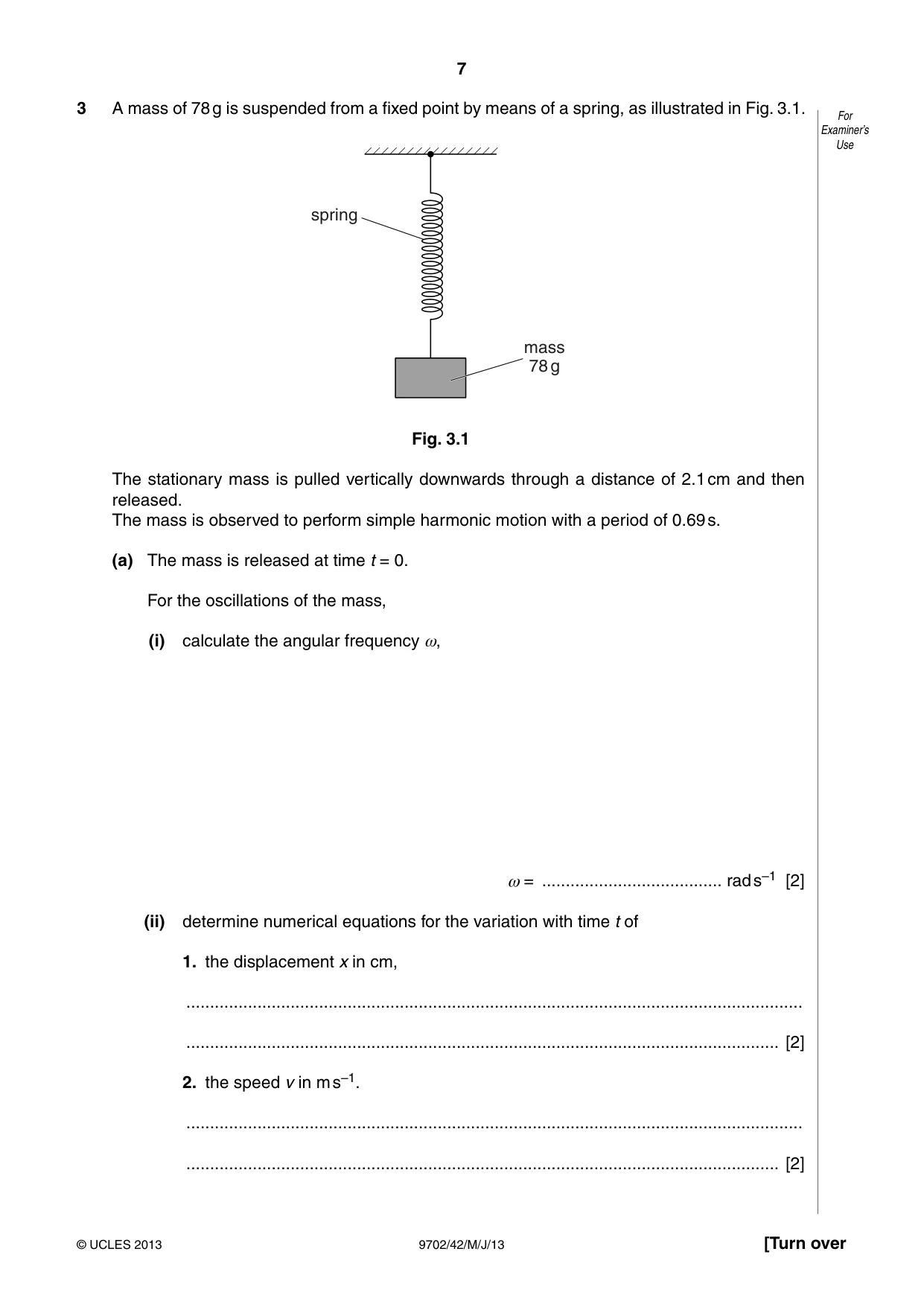
3 A mass of 78 g is suspended from a fixed point by means of a spring, as illustrated in Fig. 3.1. For Examiner’s Use spring mass 78 g Fig. 3.1 The stationary mass is pulled vertically downwards through a distance of 2.1 cm and then released. The mass is observed to perform simple harmonic motion with a period of 0.69 s. (a) The mass is released at time t = 0. For the oscillations of the mass, (i) calculate the angular frequency ω, ω = ...................................... rad s–1 [2] (ii) determine numerical equations for the variation with time t of 1. the displacement x in cm, .................................................................................................................................. ............................................................................................................................. [2] 2. the speed v in m s–1. .................................................................................................................................. ............................................................................................................................. [2] (b) Calculate the total energy of oscillation of the mass. For Examiner’s Use energy = ............................................... J [2]
Mark scheme: 3 (a) (i) ω = 2π / T = 2π / 0.69 C1 = 9.1 rad s–1 A1 [2] (allow use of f = 1.5 Hz to give ω = 9.4 rad s–1) (ii) 1. x = 2.1 cos 9.1t 2.1 and 9.1 numerical values B1 use of cos B1 [2] 2. v0 = 2.1 × 10–2 × 9.1 (allow ecf of value of x0 from (ii)1.) v0 = 0.19 m s–1 B1 v = v0 sin 9.1t (allow cos 9.1t if sin used in (ii)1.) B1 [2] (b) energy = either ½ mv02 or ½ mω2x02 = either ½ × 0.078 × 0.192 or ½ × 0.078 × 9.12 × (2.1 × 10–2)2 C1 = 1.4 × 10⁻³ J A1 [2]
Q4 · An insulated metal sphere of radius R is situated in a vacuum
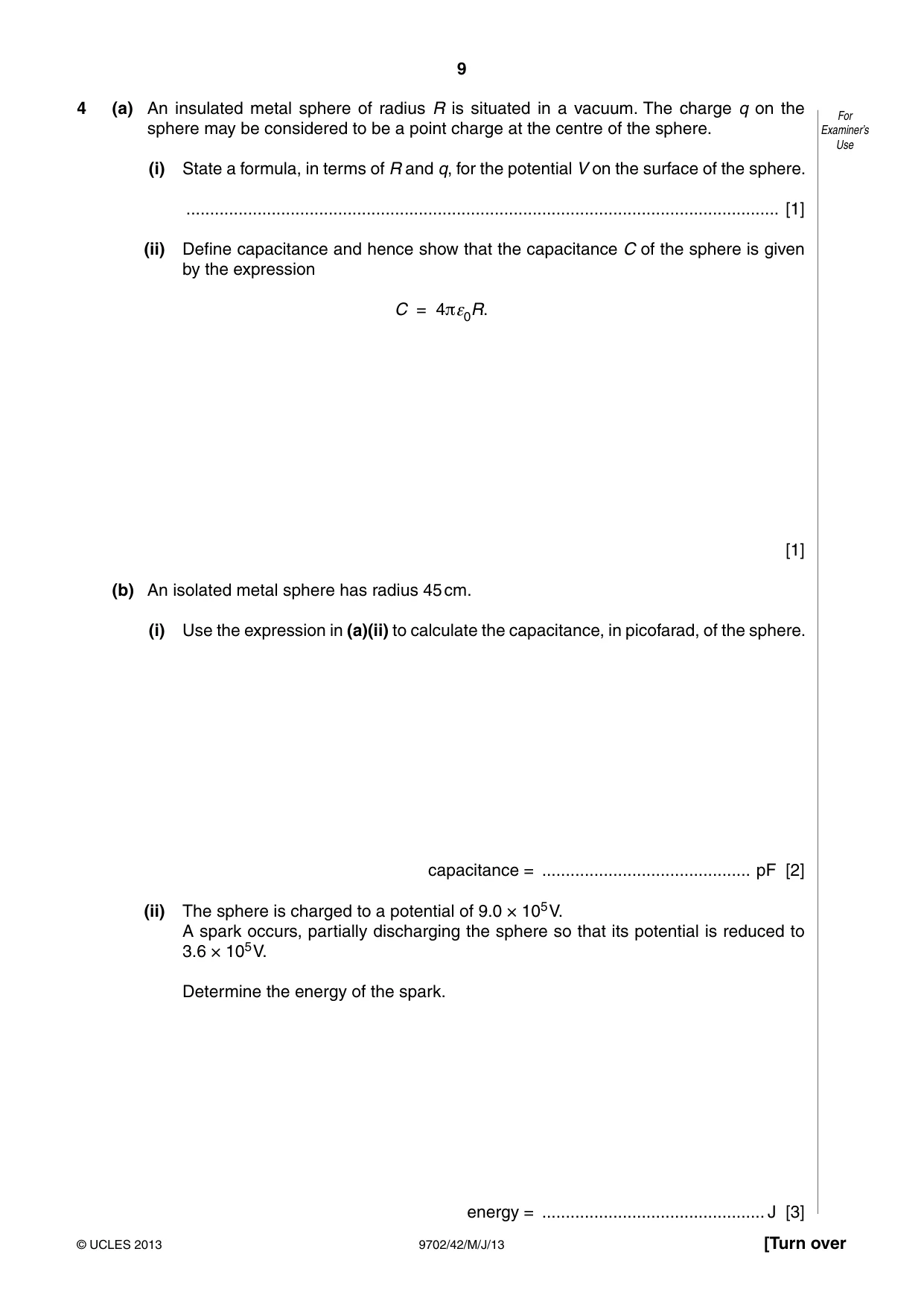
4 (a) An insulated metal sphere of radius R is situated in a vacuum. The charge q on the For sphere may be considered to be a point charge at the centre of the sphere. Examiner’s Use (i) State a formula, in terms of R and q, for the potential V on the surface of the sphere. ............................................................................................................................. [1] (ii) Define capacitance and hence show that the capacitance C of the sphere is given by the expression C = 4πε0R. [1] (b) An isolated metal sphere has radius 45 cm. (i) Use the expression in (a)(ii) to calculate the capacitance, in picofarad, of the sphere. capacitance = ............................................ pF [2] (ii) The sphere is charged to a potential of 9.0 × 10⁵ V. A spark occurs, partially discharging the sphere so that its potential is reduced to 3.6 × 10⁵ V. Determine the energy of the spark. energy = ............................................... J [3]
Mark scheme: 4 (a) (i) V = q / 4πε0R B1 [1] (ii) (capacitance is) ratio of charge and potential or q/V M1 C = q/V = 4πε0R A0 [1] (b) (i) C = 4π × 8.85 × 10–12 × 0.45 C1 = 50 pF A1 [2] (ii) either energy = ½ CV2 or energy = ½ QV and Q = CV C1 energy of spark = ½ × 50 × 10–12 {(9.0 × 10⁵)2 – (3.6 × 10⁵)2} C1 = 17 J A1 [3]
Question 5
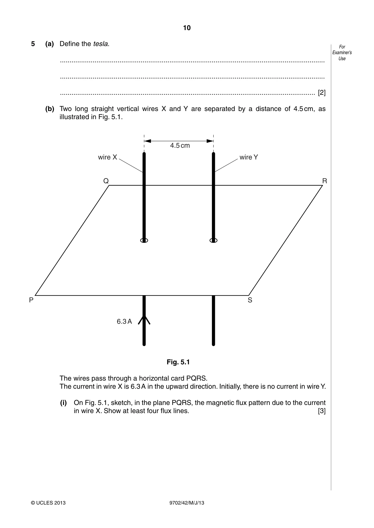
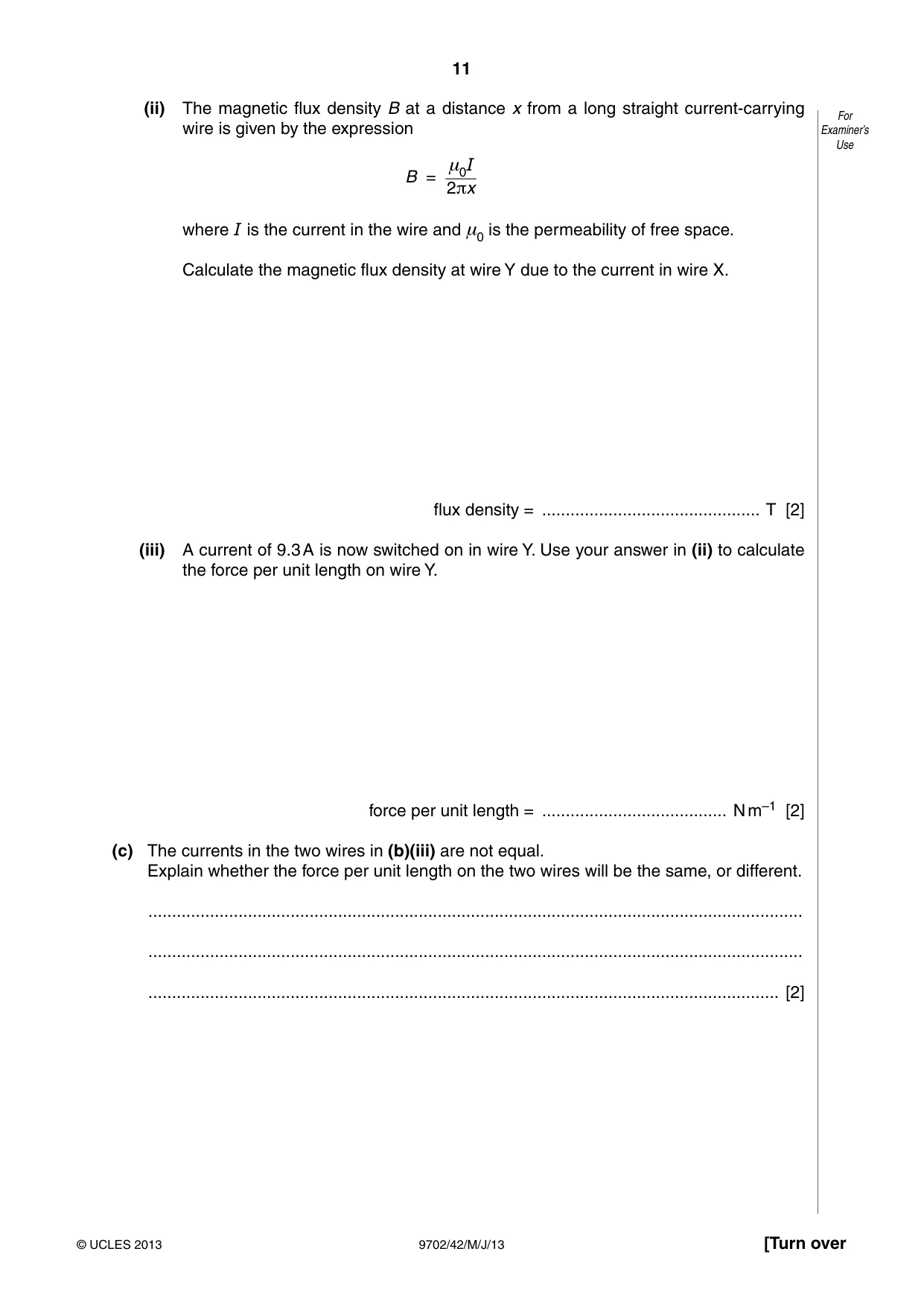
5 (a) Define the tesla. For Examiner’s .......................................................................................................................................... Use .......................................................................................................................................... ..................................................................................................................................... [2] (b) Two long straight vertical wires X and Y are separated by a distance of 4.5 cm, as illustrated in Fig. 5.1. 4.5 cm wire X wire Y Q R P S 6.3 A Fig. 5.1 The wires pass through a horizontal card PQRS. The current in wire X is 6.3 A in the upward direction. Initially, there is no current in wire Y. (i) On Fig. 5.1, sketch, in the plane PQRS, the magnetic flux pattern due to the current in wire X. Show at least four flux lines. [3] (ii) The magnetic flux density B at a distance x from a long straight current-carrying For wire is given by the expression Examiner’s Use μ0I B = 2πx where I is the current in the wire and μ0 is the permeability of free space. Calculate the magnetic flux density at wire Y due to the current in wire X. flux density = .............................................. T [2] (iii) A current of 9.3 A is now switched on in wire Y. Use your answer in (ii) to calculate the force per unit length on wire Y. force per unit length = ....................................... N m–1 [2] (c) The currents in the two wires in (b)(iii) are not equal. Explain whether the force per unit length on the two wires will be the same, or different. .......................................................................................................................................... .......................................................................................................................................... ..................................................................................................................................... [2]
Mark scheme: 5 (a) (uniform magnetic) flux normal to long (straight) wire carrying a current of 1 A M1 (creates) force per unit length of 1 N m–1 A1 [2] (b) (i) sketch: concentric circles M1 increasing separation (must show more than 3 circles) A1 correct direction (anticlockwise, looking down) B1 [3] (ii) B = (4π × 10–7 × 6.3) / (2π × 4.5 × 10–2) C1 = 2.8 × 10⁻⁵ T A1 [2] (iii) F = BIL (sinθ) C1 = 2.8 × 10–5 × 9.3 × 1 F/L = 2.6 × 10⁻⁴ N m–1 A1 [2] (c) force per unit length depends on product IXIY / by Newton’s third law / action and reaction are equal and opposite M1 so same for both A1 [2] GCE AS/A LEVEL – May/June 2013 9702 42
Q6 · State Faraday’s law of electromagnetic induction
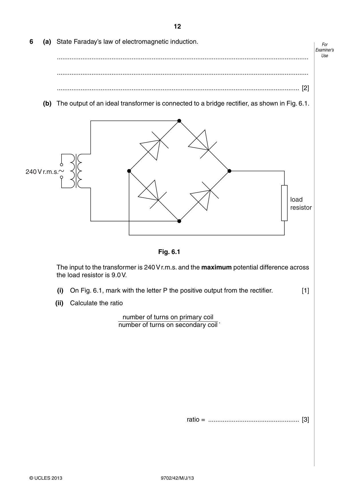
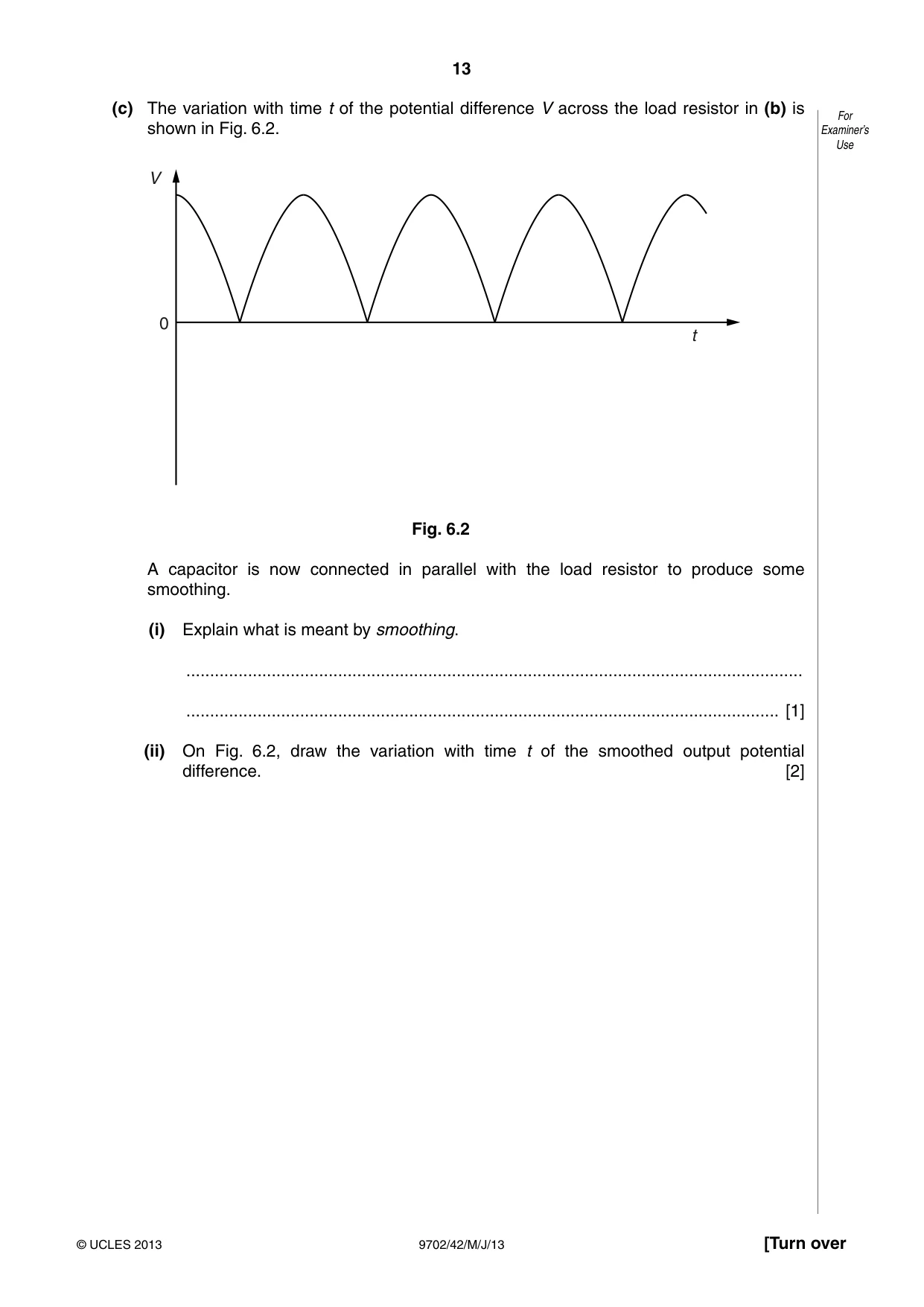
6 (a) State Faraday’s law of electromagnetic induction. For Examiner’s .......................................................................................................................................... Use .......................................................................................................................................... ..................................................................................................................................... [2] (b) The output of an ideal transformer is connected to a bridge rectifier, as shown in Fig. 6.1. 240 V r.m.s. load resistor Fig. 6.1 The input to the transformer is 240 V r.m.s. and the maximum potential difference across the load resistor is 9.0 V. (i) On Fig. 6.1, mark with the letter P the positive output from the rectifier. [1] (ii) Calculate the ratio number of turns on primary coil . number of turns on secondary coil ratio = .................................................. [3] (c) The variation with time t of the potential difference V across the load resistor in (b) is For shown in Fig. 6.2. Examiner’s Use V 0 t Fig. 6.2 A capacitor is now connected in parallel with the load resistor to produce some smoothing. (i) Explain what is meant by smoothing. .................................................................................................................................. ............................................................................................................................. [1] (ii) On Fig. 6.2, draw the variation with time t of the smoothed output potential difference. [2]
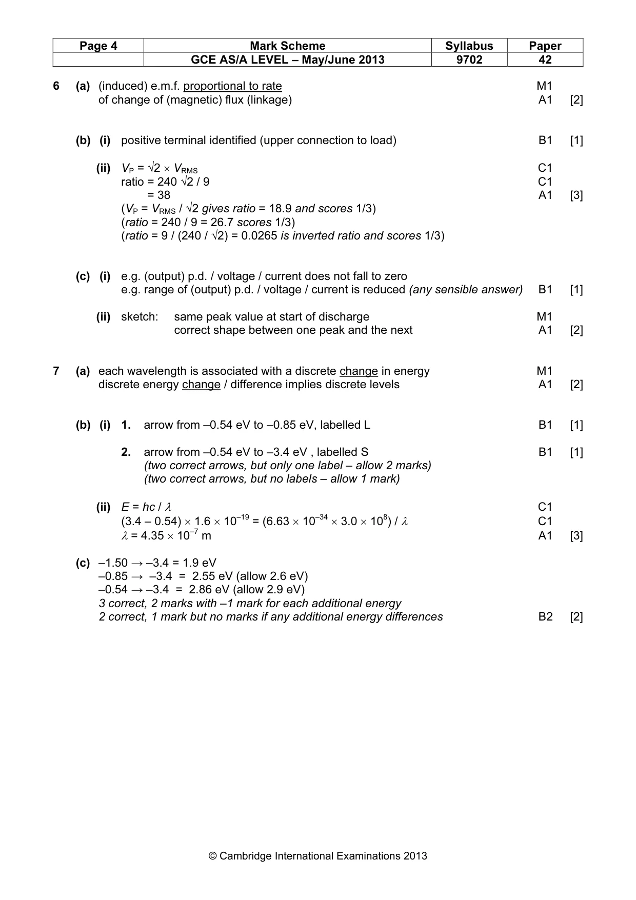
Mark scheme: 6 (a) (induced) e.m.f. proportional to rate M1 of change of (magnetic) flux (linkage) A1 [2] (b) (i) positive terminal identified (upper connection to load) B1 [1] (ii) VP = √2 × VRMS C1 ratio = 240 √2 / 9 C1 ratio = 38 A1 [3] (VP = VRMS / √2 gives ratio = 18.9 and scores 1/3) (ratio = 240 / 9 = 26.7 scores 1/3) (ratio = 9 / (240 / √2) = 0.0265 is inverted ratio and scores 1/3) (c) (i) e.g. (output) p.d. / voltage / current does not fall to zero e.g. range of (output) p.d. / voltage / current is reduced (any sensible answer) B1 [1] (ii) sketch: same peak value at start of discharge M1 correct shape between one peak and the next A1 [2]
Q7 · The emission spectrum of atomic hydrogen consists of a number of discrete wavelengths
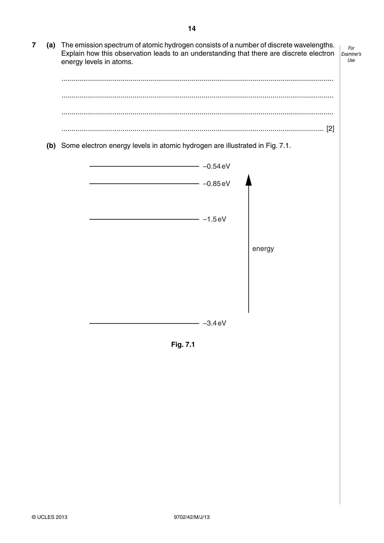
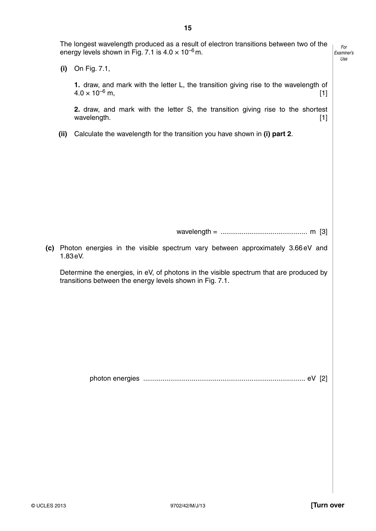
7 (a) The emission spectrum of atomic hydrogen consists of a number of discrete wavelengths. For Explain how this observation leads to an understanding that there are discrete electron Examiner’s energy levels in atoms. Use .......................................................................................................................................... .......................................................................................................................................... .......................................................................................................................................... ..................................................................................................................................... [2] (b) Some electron energy levels in atomic hydrogen are illustrated in Fig. 7.1. –0.54 eV –0.85 eV –1.5 eV energy –3.4 eV Fig. 7.1 The longest wavelength produced as a result of electron transitions between two of the For energy levels shown in Fig. 7.1 is 4.0 × 10⁻⁶ m. Examiner’s Use (i) On Fig. 7.1, 1. draw, and mark with the letter L, the transition giving rise to the wavelength of 4.0 × 10⁻⁶ m, [1] 2. draw, and mark with the letter S, the transition giving rise to the shortest wavelength. [1] (ii) Calculate the wavelength for the transition you have shown in (i) part 2. wavelength = ............................................. m [3] (c) Photon energies in the visible spectrum vary between approximately 3.66 eV and 1.83 eV. Determine the energies, in eV, of photons in the visible spectrum that are produced by transitions between the energy levels shown in Fig. 7.1. photon energies .................................................................................... eV [2]
Mark scheme: 7 (a) each wavelength is associated with a discrete change in energy M1 discrete energy change / difference implies discrete levels A1 [2] (b) (i) 1. arrow from –0.54 eV to –0.85 eV, labelled L B1 [1] 2. arrow from –0.54 eV to –3.4 eV , labelled S B1 [1] (two correct arrows, but only one label – allow 2 marks) (two correct arrows, but no labels – allow 1 mark) (ii) E = hc / λ C1 (3.4 – 0.54) × 1.6 × 10–19 = (6.63 × 10–34 × 3.0 × 108) / λ C1 λ = 4.35 × 10⁻⁷ m A1 [3] (c) –1.50 → –3.4 = 1.9 eV –0.85 → –3.4 = 2.55 eV (allow 2.6 eV) –0.54 → –3.4 = 2.86 eV (allow 2.9 eV) 3 correct, 2 marks with –1 mark for each additional energy 2 correct, 1 mark but no marks if any additional energy differences B2 [2] GCE AS/A LEVEL – May/June 2013 9702 42
Q8 · Explain why the mass of an α-particle is less than the total mass of two individual For…
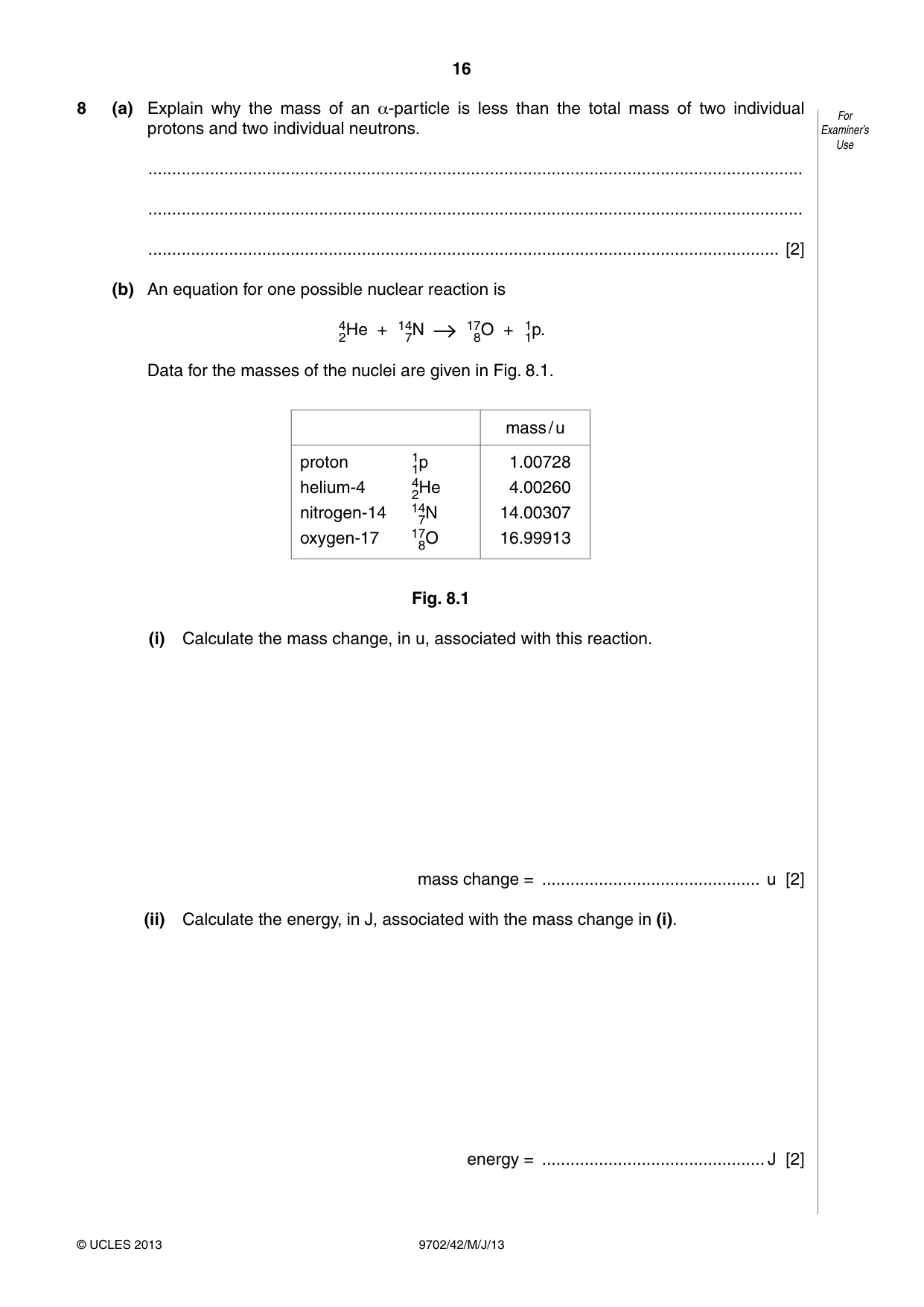
8 (a) Explain why the mass of an α-particle is less than the total mass of two individual For protons and two individual neutrons. Examiner’s Use .......................................................................................................................................... .......................................................................................................................................... ..................................................................................................................................... [2] (b) An equation for one possible nuclear reaction is 42He + 147N 178O + 11p. Data for the masses of the nuclei are given in Fig. 8.1. mass / u proton 11p 1.00728 helium-4 42He 4.00260 nitrogen-14 147N 14.00307 oxygen-17 178O 16.99913 Fig. 8.1 (i) Calculate the mass change, in u, associated with this reaction. mass change = .............................................. u [2] (ii) Calculate the energy, in J, associated with the mass change in (i). energy = ............................................... J [2] (iii) Suggest and explain why, for this reaction to occur, the helium-4 nucleus must have For a minimum speed. Examiner’s Use .................................................................................................................................. .................................................................................................................................. ............................................................................................................................. [2]
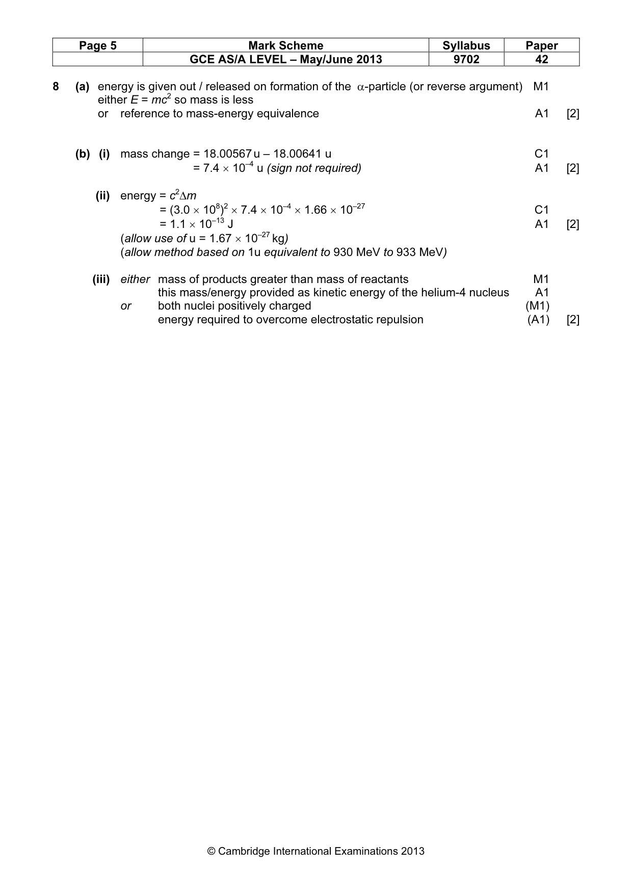
Mark scheme: 8 (a) energy is given out / released on formation of the α-particle (or reverse argument) M1 either E = mc2 so mass is less or reference to mass-energy equivalence A1 [2] (b) (i) mass change = 18.00567 u – 18.00641 u C1 = 7.4 × 10⁻⁴ u (sign not required) A1 [2] (ii) energy = c2∆m = (3.0 × 10⁸)2 × 7.4 × 10–4 × 1.66 × 10–27 C1 = 1.1 × 10⁻¹³ J A1 [2] (allow use of u = 1.67 × 10⁻²⁷ kg) (allow method based on 1u equivalent to 930 MeV to 933 MeV) (iii) either mass of products greater than mass of reactants M1 this mass/energy provided as kinetic energy of the helium-4 nucleus A1 or both nuclei positively charged (M1) energy required to overcome electrostatic repulsion (A1) [2] GCE AS/A LEVEL – May/June 2013 9702 42 Section B
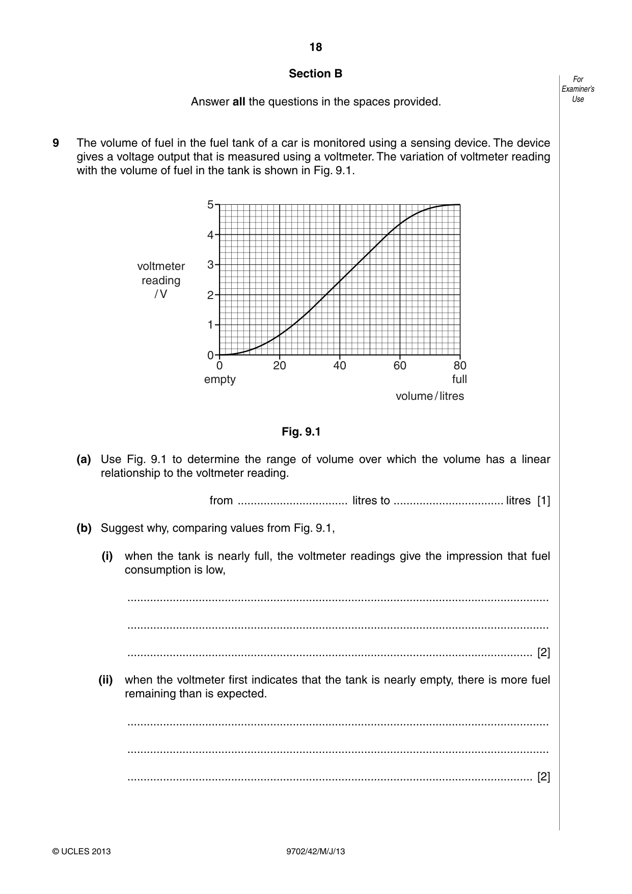
Q9 · The volume of fuel in the fuel tank of a car is monitored using a sensing device
9 The volume of fuel in the fuel tank of a car is monitored using a sensing device. The device gives a voltage output that is measured using a voltmeter. The variation of voltmeter reading with the volume of fuel in the tank is shown in Fig. 9.1. 5 4 voltmeter 3 reading / V 2 1 0 0 20 40 60 80 empty full volume / litres Fig. 9.1 (a) Use Fig. 9.1 to determine the range of volume over which the volume has a linear relationship to the voltmeter reading. from .................................. litres to .................................. litres [1] (b) Suggest why, comparing values from Fig. 9.1, (i) when the tank is nearly full, the voltmeter readings give the impression that fuel consumption is low, .................................................................................................................................. .................................................................................................................................. ............................................................................................................................. [2] (ii) when the voltmeter first indicates that the tank is nearly empty, there is more fuel remaining than is expected. .................................................................................................................................. .................................................................................................................................. ............................................................................................................................. [2]
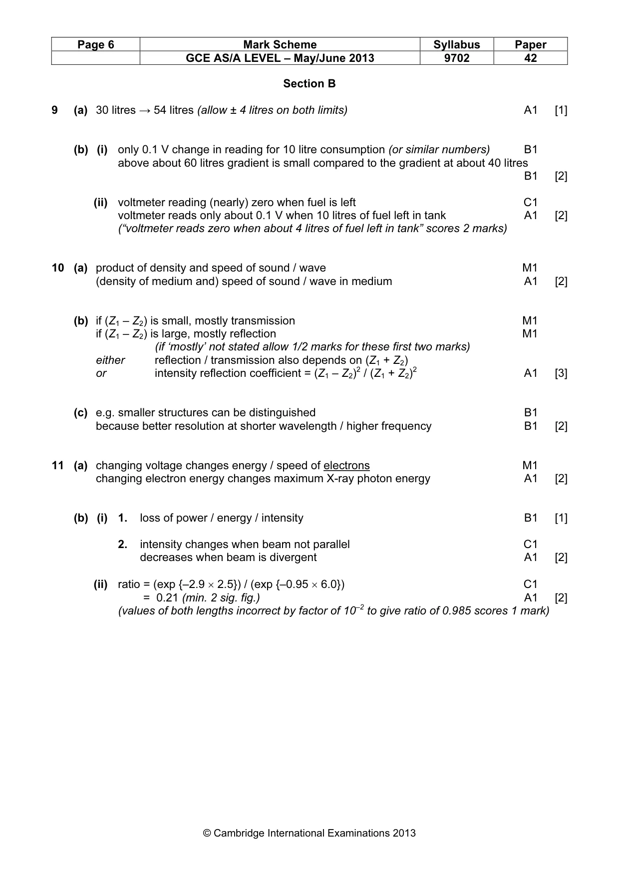
Mark scheme: 9 (a) 30 litres → 54 litres (allow ± 4 litres on both limits) A1 [1] (b) (i) only 0.1 V change in reading for 10 litre consumption (or similar numbers) B1 above about 60 litres gradient is small compared to the gradient at about 40 litres B1 [2] (ii) voltmeter reading (nearly) zero when fuel is left C1 voltmeter reads only about 0.1 V when 10 litres of fuel left in tank A1 [2] (“voltmeter reads zero when about 4 litres of fuel left in tank” scores 2 marks)
Q10 · By reference to ultrasound waves, state what is meant by acoustic impedance
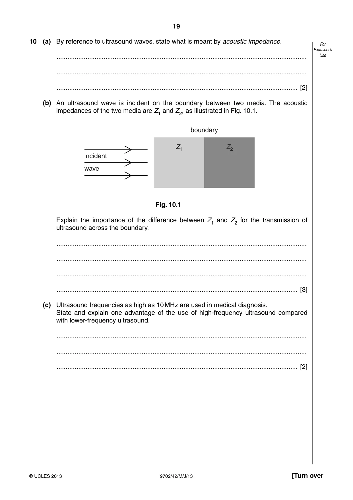
10 (a) By reference to ultrasound waves, state what is meant by acoustic impedance. For Examiner’s .......................................................................................................................................... Use .......................................................................................................................................... ..................................................................................................................................... [2] (b) An ultrasound wave is incident on the boundary between two media. The acoustic impedances of the two media are Z1 and Z2, as illustrated in Fig. 10.1. boundary Z1 Z2 incident wave Fig. 10.1 Explain the importance of the difference between Z1 and Z2 for the transmission of ultrasound across the boundary. .......................................................................................................................................... .......................................................................................................................................... .......................................................................................................................................... ..................................................................................................................................... [3] (c) Ultrasound frequencies as high as 10 MHz are used in medical diagnosis. State and explain one advantage of the use of high-frequency ultrasound compared with lower-frequency ultrasound. .......................................................................................................................................... .......................................................................................................................................... ..................................................................................................................................... [2]
Mark scheme: 10 (a) product of density and speed of sound / wave M1 (density of medium and) speed of sound / wave in medium A1 [2] (b) if (Z1 – Z2) is small, mostly transmission M1 if (Z1 – Z2) is large, mostly reflection M1 (if ‘mostly’ not stated allow 1/2 marks for these first two marks) either reflection / transmission also depends on (Z1 + Z2) or intensity reflection coefficient = (Z1 – Z2)2 / (Z1 + Z2)2 A1 [3] (c) e.g. smaller structures can be distinguished B1 because better resolution at shorter wavelength / higher frequency B1 [2]
Q11 · Explain how the hardness of an X-ray beam is controlled by the accelerating voltage in…
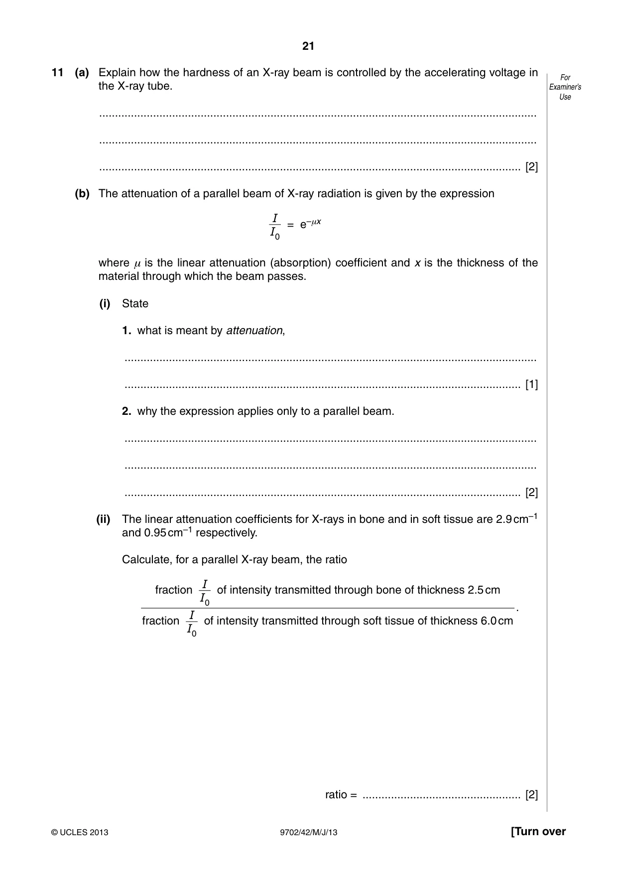
11 (a) Explain how the hardness of an X-ray beam is controlled by the accelerating voltage in For the X-ray tube. Examiner’s Use .......................................................................................................................................... .......................................................................................................................................... ..................................................................................................................................... [2] (b) The attenuation of a parallel beam of X-ray radiation is given by the expression I = e–μx I0 where μ is the linear attenuation (absorption) coefficient and x is the thickness of the material through which the beam passes. (i) State 1. what is meant by attenuation, .................................................................................................................................. ............................................................................................................................. [1] 2. why the expression applies only to a parallel beam. .................................................................................................................................. .................................................................................................................................. ............................................................................................................................. [2] (ii) The linear attenuation coefficients for X-rays in bone and in soft tissue are 2.9 cm–1 and 0.95 cm–1 respectively. Calculate, for a parallel X-ray beam, the ratio I fraction of intensity transmitted through bone of thickness 2.5 cm I0 . I fraction of intensity transmitted through soft tissue of thickness 6.0 cm I0 ratio = .................................................. [2]
Mark scheme: 11 (a) changing voltage changes energy / speed of electrons M1 changing electron energy changes maximum X-ray photon energy A1 [2] (b) (i) 1. loss of power / energy / intensity B1 [1] 2. intensity changes when beam not parallel C1 decreases when beam is divergent A1 [2] (ii) ratio = (exp {–2.9 × 2.5}) / (exp {–0.95 × 6.0}) C1 = 0.21 (min. 2 sig. fig.) A1 [2] (values of both lengths incorrect by factor of 10–2 to give ratio of 0.985 scores 1 mark) GCE AS/A LEVEL – May/June 2013 9702 42
Q12 · The digital transmission of speech may be represented by the block diagram of Fig
12 The digital transmission of speech may be represented by the block diagram of Fig. 12.1. For Examiner’s Use parallel- serial- to- to- ADC DAC serial parallel converter converter Fig. 12.1 (a) State the purpose of the parallel-to-serial converter. .......................................................................................................................................... .......................................................................................................................................... ..................................................................................................................................... [2] (b) Part of the signal from the microphone is shown in Fig. 12.2. 16 14 12 10 microphone output 8 / mV 6 4 2 0 0 0.2 0.4 0.6 0.8 1.0 1.2 time / ms Fig. 12.2 The ADC (analogue-to-digital converter) samples the analogue signal at a frequency For of 5.0 kHz. Examiner’s Each sample from the ADC is a four-bit digital number where the smallest bit represents Use 1.0 mV. The first sample is taken at time zero. Use Fig. 12.2 to determine the four-bit digital number produced by the ADC at times (i) 0.4 ms, ............................................................................................................................. [1] (ii) 0.8 ms. ............................................................................................................................. [1] (c) The digital signal is transmitted and then converted to an analogue form by the DAC (digital-to-analogue converter). Using data from Fig. 12.2, draw, on the axes of Fig. 12.3, the output level of the transmitted analogue signal for time zero to time 1.2 ms. 16 14 output 12 level 10 8 6 4 2 0 0 0.2 0.4 0.6 0.8 1.0 1.2 time / ms [4] Fig. 12.3 (d) State and explain the effect on the transmitted analogue waveform of increasing, for the ADC and the DAC, both the sampling frequency and the number of bits in each sample. .......................................................................................................................................... .......................................................................................................................................... .......................................................................................................................................... ..................................................................................................................................... [3]
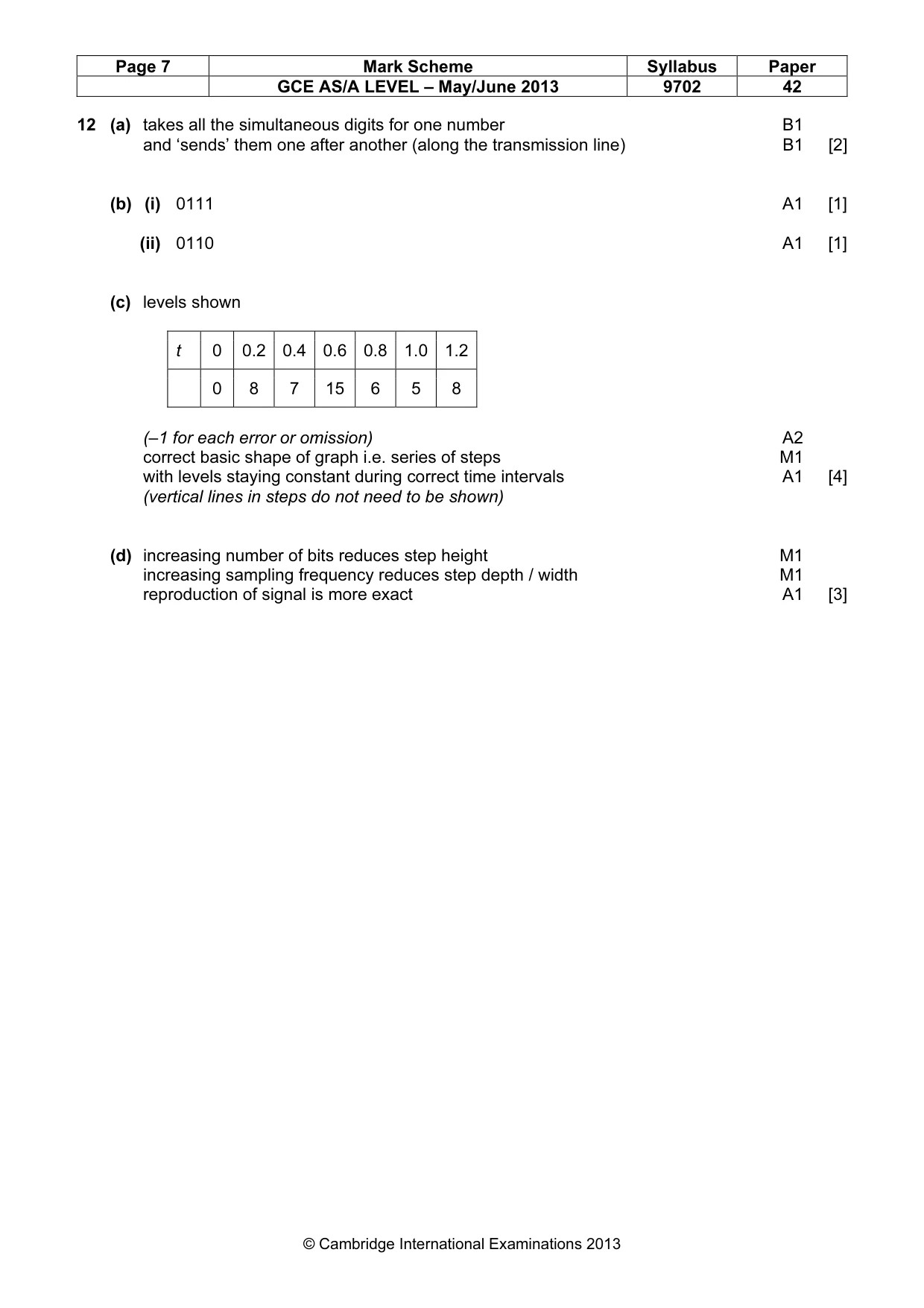
Mark scheme: 12 (a) takes all the simultaneous digits for one number B1 and ‘sends’ them one after another (along the transmission line) B1 [2] (b) (i) 0111 A1 [1] (ii) 0110 A1 [1] (c) levels shown t 0 0.2 0.4 0.6 0.8 1.0 1.2 0 8 7 15 6 5 8 (–1 for each error or omission) A2 correct basic shape of graph i.e. series of steps M1 with levels staying constant during correct time intervals A1 [4] (vertical lines in steps do not need to be shown) (d) increasing number of bits reduces step height M1 increasing sampling frequency reduces step depth / width M1 reproduction of signal is more exact A1 [3]
What was in this paper
The subtopics covered by these 12 questions, and how many questions each got. Open one in a new tab to see every Cambridge question on it.
1Characteristics of alternating currents1Electric current1Energy levels in atoms and line spectra1Equation of state1Gravitational force between point masses1Magnetic fields due to currents1Mass defect and nuclear binding energy1Production and use of ultrasound1Production and use of X-rays1Rectification and smoothing1Simple harmonic oscillations1What you needed in this session
Cambridge’s own grade thresholds for 2013 May/June, Paper 4 · Variant 2. A higher threshold means an easier paper — the bar moves with how the cohort did.