Cambridge A Level Physics 9702 — 2010 Oct/Nov Paper 4 · Variant 3
9702/43/O/N/10 · 12 questions · 100 marks · ≈113 min
The question paper and its mark scheme, free to read here and free to download. This is Cambridge’s own paper, exactly as it was sat.
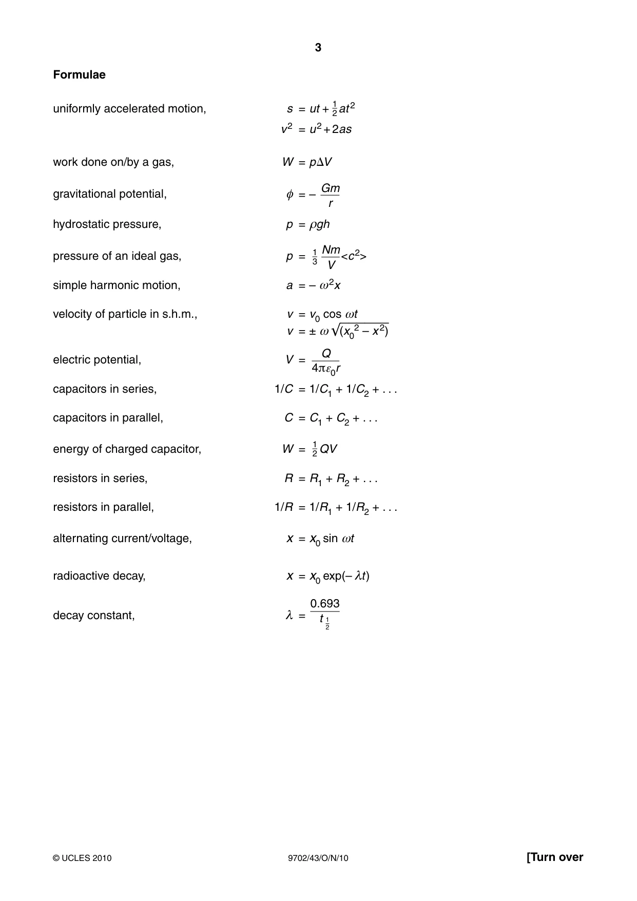
Question paper24 pages


Mark scheme6 pages
Answers below. Sit the paper first if you are practising.
Questions as text
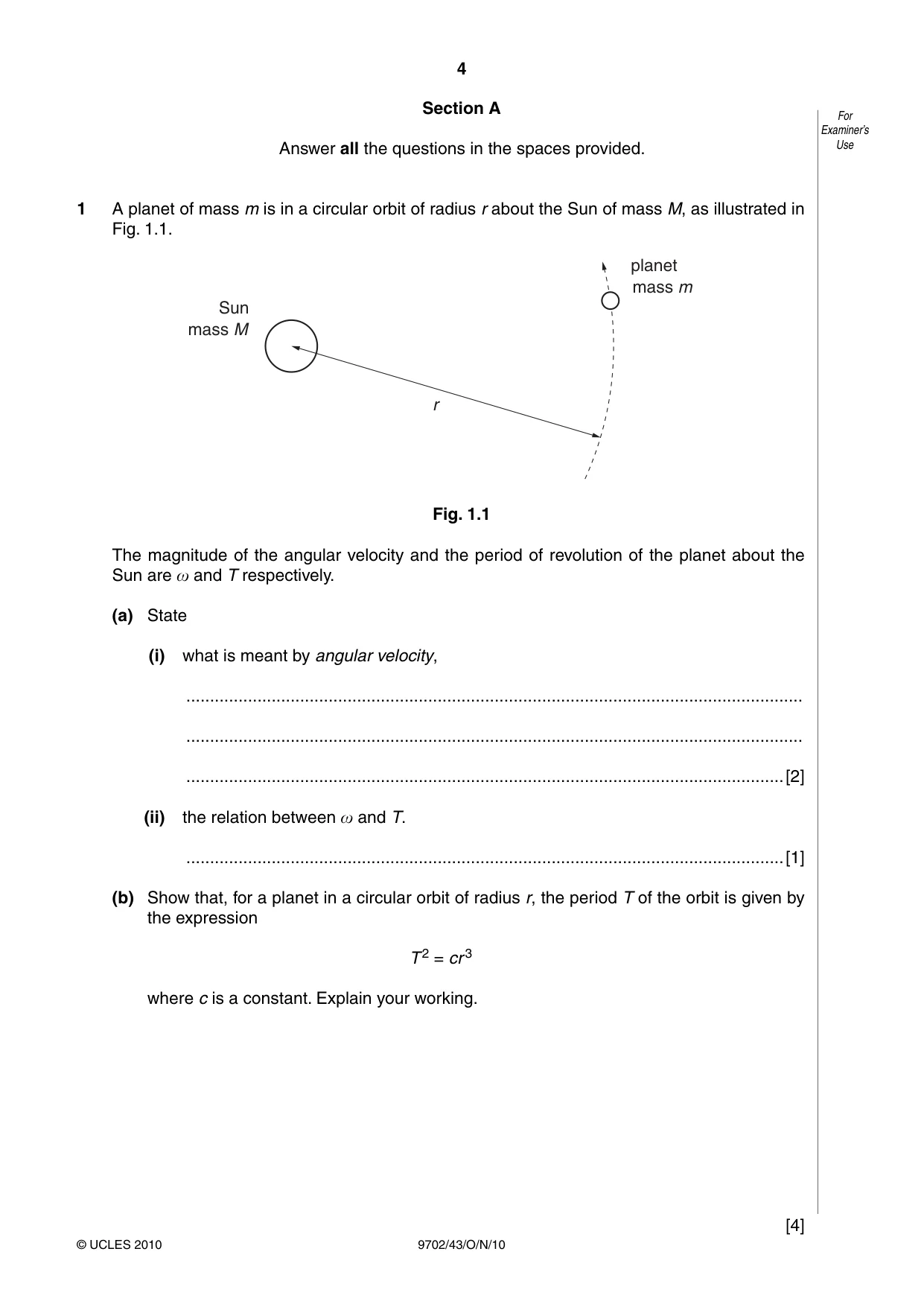
Q1 · A planet of mass m is in a circular orbit of radius r about the Sun of mass M, as…
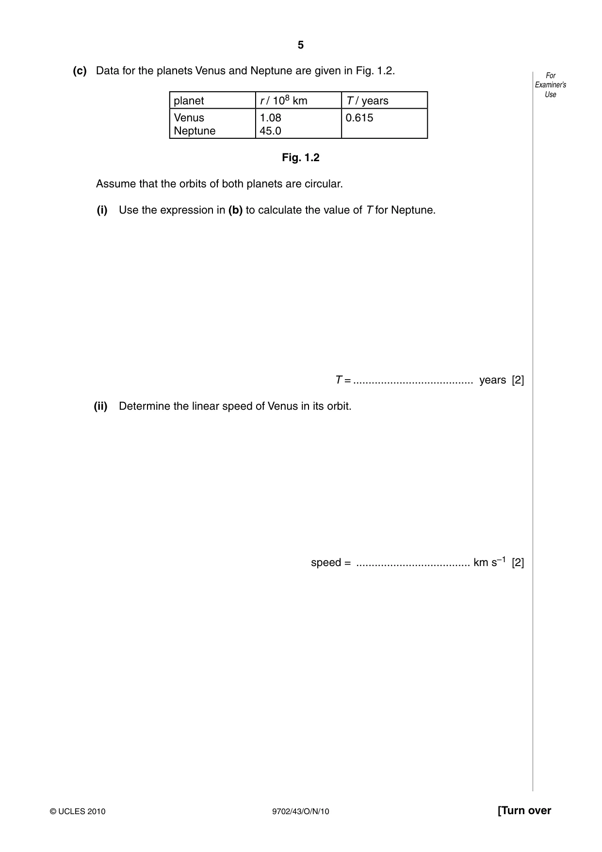
1 A planet of mass m is in a circular orbit of radius r about the Sun of mass M, as illustrated in Fig. 1.1. planet mass m Sun mass M r Fig. 1.1 The magnitude of the angular velocity and the period of revolution of the planet about the Sun are x and T respectively. (a) State (i) what is meant by angular velocity, .................................................................................................................................. .................................................................................................................................. ..............................................................................................................................[2] (ii) the relation between x and T. ..............................................................................................................................[1] (b) Show that, for a planet in a circular orbit of radius r, the period T of the orbit is given by the expression T 2 = cr 3 where c is a constant. Explain your working. [4] (c) Data for the planets Venus and Neptune are given in Fig. 1.2. For Examiner’s Use planet r / 108 km T / years Venus 1.08 0.615 Neptune 45.0 Fig. 1.2 Assume that the orbits of both planets are circular. (i) Use the expression in (b) to calculate the value of T for Neptune. T = ....................................... years [2] (ii) Determine the linear speed of Venus in its orbit. speed = ..................................... km s–1 [2]
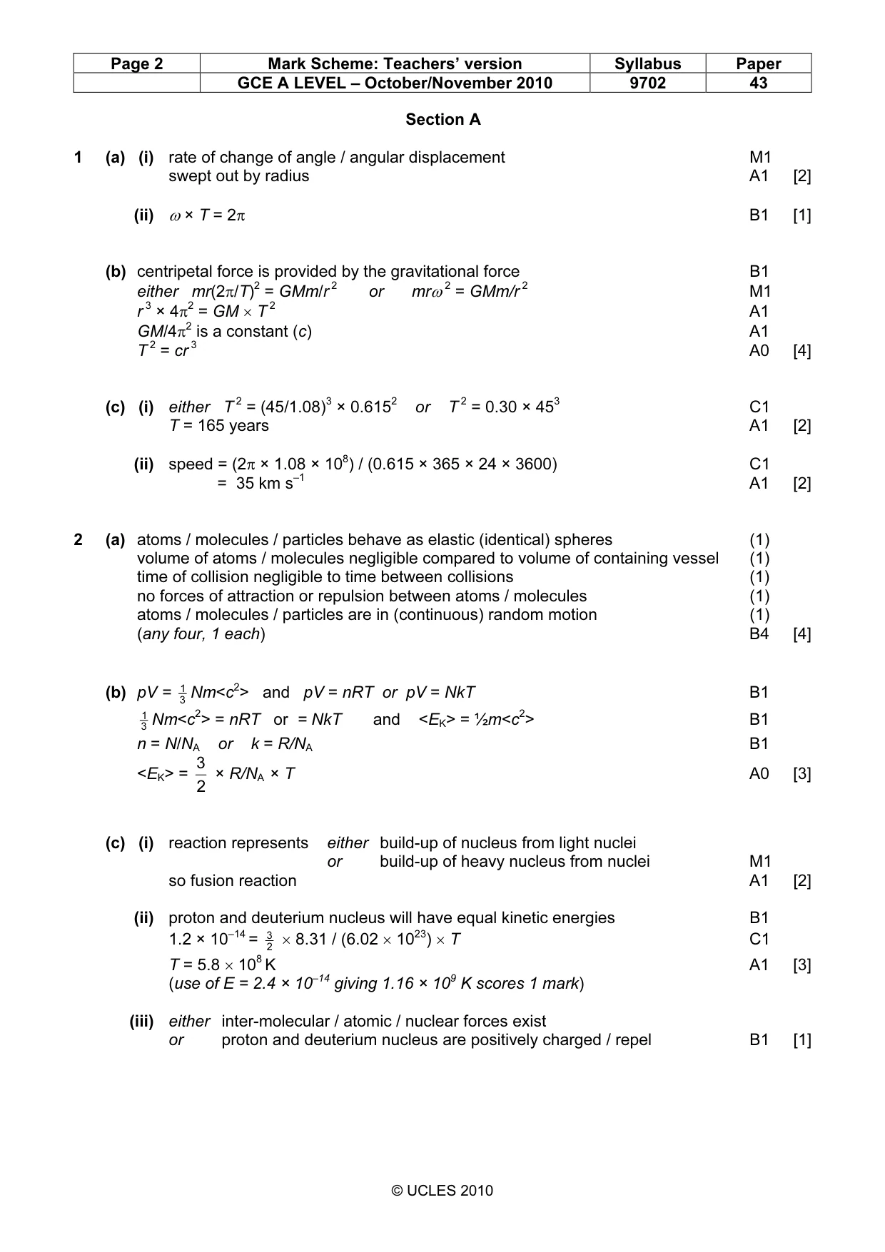
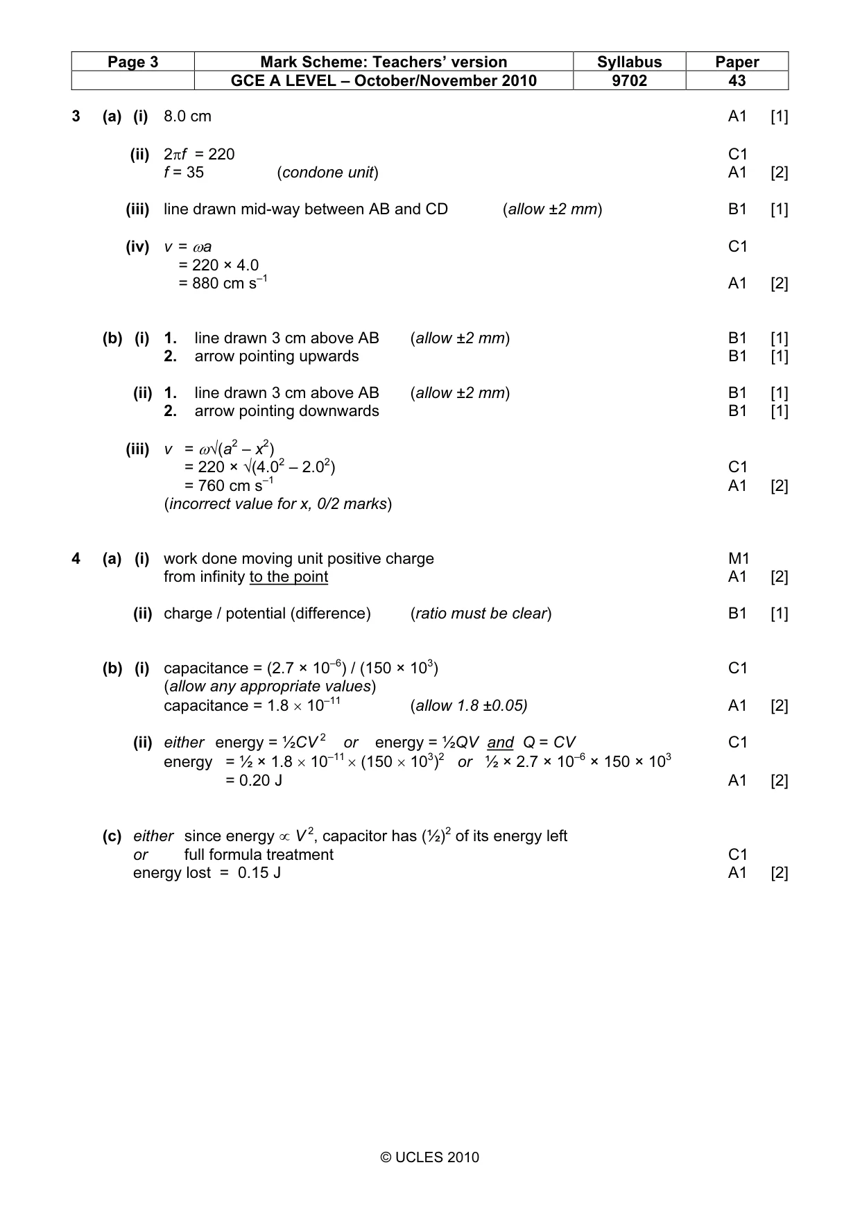
Mark scheme: 1 (a) (i) rate of change of angle / angular displacement M1 swept out by radius A1 [2] (ii) ω × T = 2π B1 [1] (b) centripetal force is provided by the gravitational force B1 either mr(2π/T)2 = GMm/r 2 or mrω 2 = GMm/r 2 M1 r 3 × 4π2 = GM × T 2 A1 GM/4π2 is a constant (c) A1 T 2 = cr 3 A0 [4] (c) (i) either T 2 = (45/1.08)3 × 0.6152 or T 2 = 0.30 × 453 C1 T = 165 years A1 [2] (ii) speed = (2π × 1.08 × 108) / (0.615 × 365 × 24 × 3600) C1 = 35 km s–1 A1 [2]
Q2 · State the basic assumptions of the kinetic theory of gases
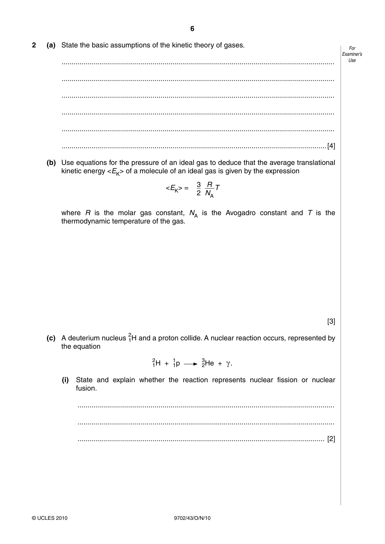
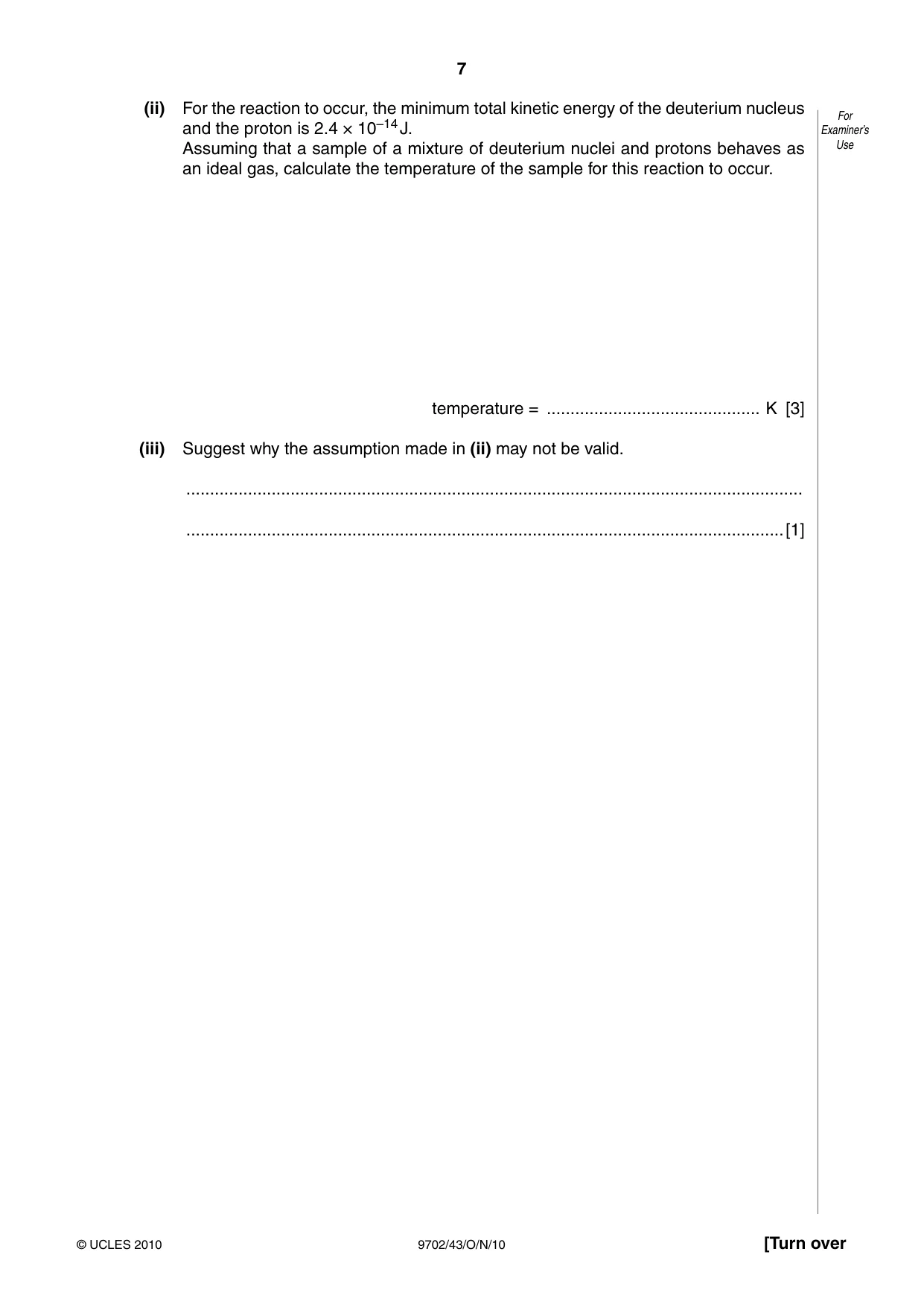
2 (a) State the basic assumptions of the kinetic theory of gases. For Examiner’s .......................................................................................................................................... Use .......................................................................................................................................... .......................................................................................................................................... .......................................................................................................................................... .......................................................................................................................................... ......................................................................................................................................[4] (b) Use equations for the pressure of an ideal gas to deduce that the average translational kinetic energy <EK> of a molecule of an ideal gas is given by the expression 3 R <EK> = T 2 NA where R is the molar gas constant, NA is the Avogadro constant and T is the thermodynamic temperature of the gas. [3] 2 (c) A deuterium nucleus 1H and a proton collide. A nuclear reaction occurs, represented by the equation 2 1 3 1H + 1p 2He + c. (i) State and explain whether the reaction represents nuclear fission or nuclear fusion. .................................................................................................................................. .................................................................................................................................. ............................................................................................................................. [2] (ii) For the reaction to occur, the minimum total kinetic energy of the deuterium nucleus For and the proton is 2.4 × 10⁻¹⁴ J. Examiner’s Assuming that a sample of a mixture of deuterium nuclei and protons behaves as Use an ideal gas, calculate the temperature of the sample for this reaction to occur. temperature = ............................................. K [3] (iii) Suggest why the assumption made in (ii) may not be valid. .................................................................................................................................. ..............................................................................................................................[1]
Mark scheme: 2 (a) atoms / molecules / particles behave as elastic (identical) spheres (1) volume of atoms / molecules negligible compared to volume of containing vessel (1) time of collision negligible to time between collisions (1) no forces of attraction or repulsion between atoms / molecules (1) atoms / molecules / particles are in (continuous) random motion (1) (any four, 1 each) B4 [4] (b) pV = 31 Nm<c2> and pV = nRT or pV = NkT B1 1 Nm<c2> = nRT or = NkT and <EK> = ½m<c2> B1 3 n = N/NA or k = R/NA B1 3 <EK> = × R/NA × T A0 [3] 2 (c) (i) reaction represents either build-up of nucleus from light nuclei or build-up of heavy nucleus from nuclei M1 so fusion reaction A1 [2] (ii) proton and deuterium nucleus will have equal kinetic energies B1 1.2 × 10–14 = 32 × 8.31 / (6.02 × 10²³) × T C1 T = 5.8 × 10⁸ K A1 [3] (use of E = 2.4 × 10⁻¹⁴ giving 1.16 × 10⁹ K scores 1 mark) (iii) either inter-molecular / atomic / nuclear forces exist or proton and deuterium nucleus are positively charged / repel B1 [1] GCE A LEVEL – October/November 2010 9702 43
Q3 · A cylinder and piston, used in a car engine, are illustrated in Fig
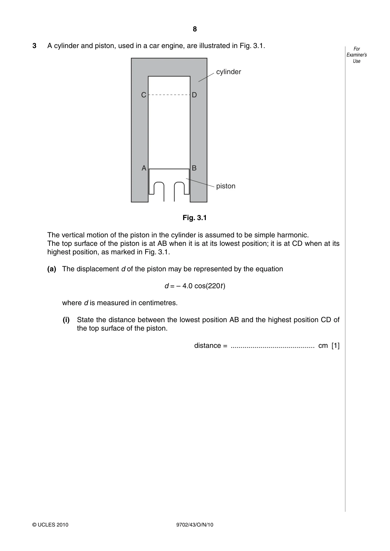
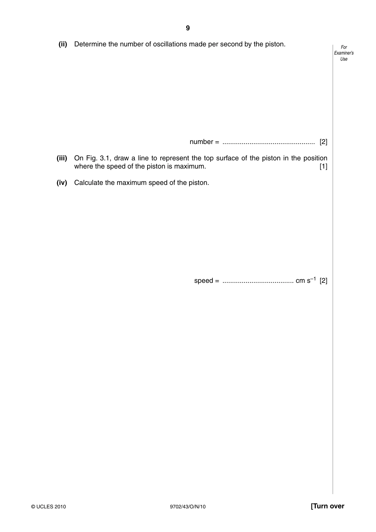
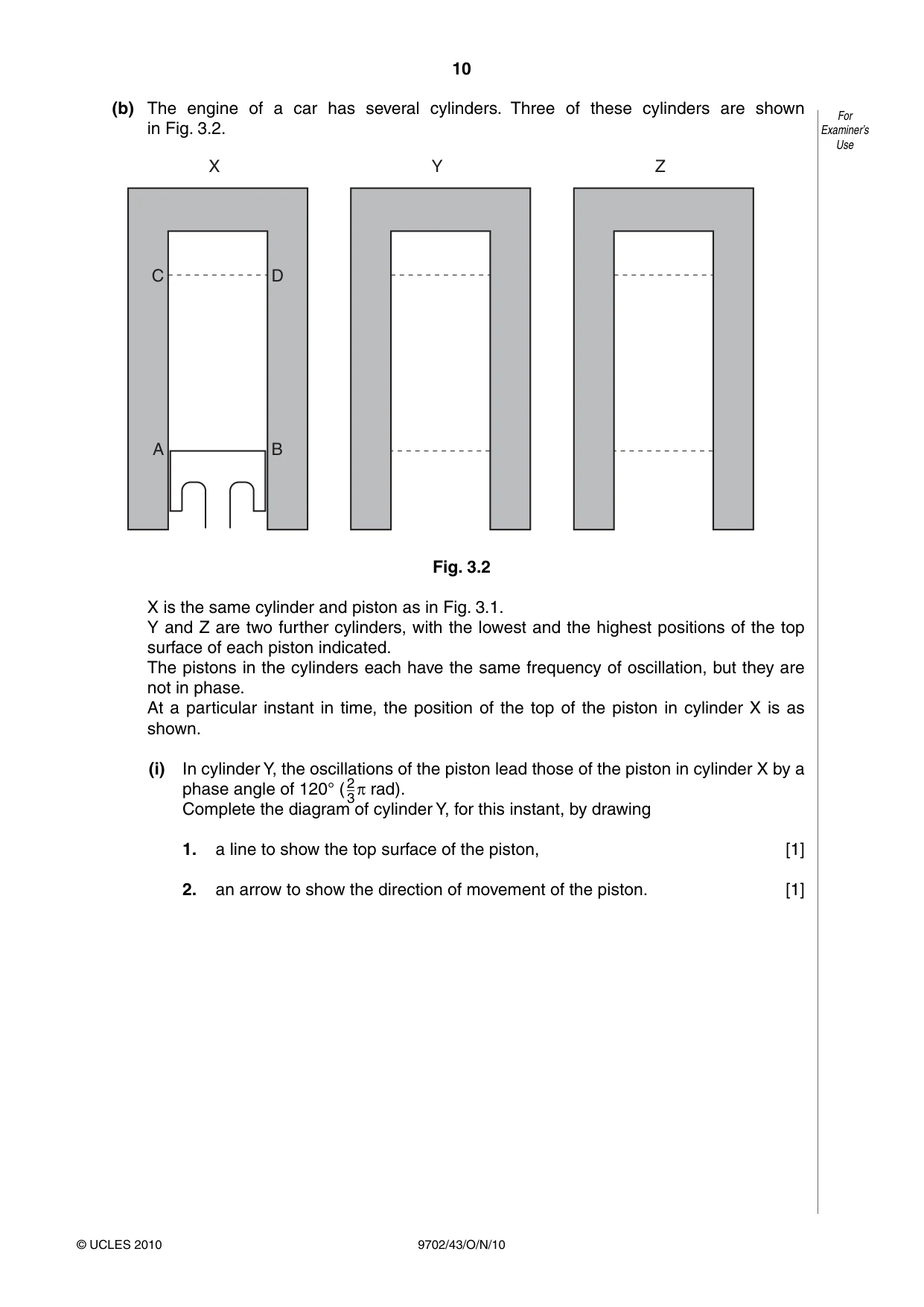
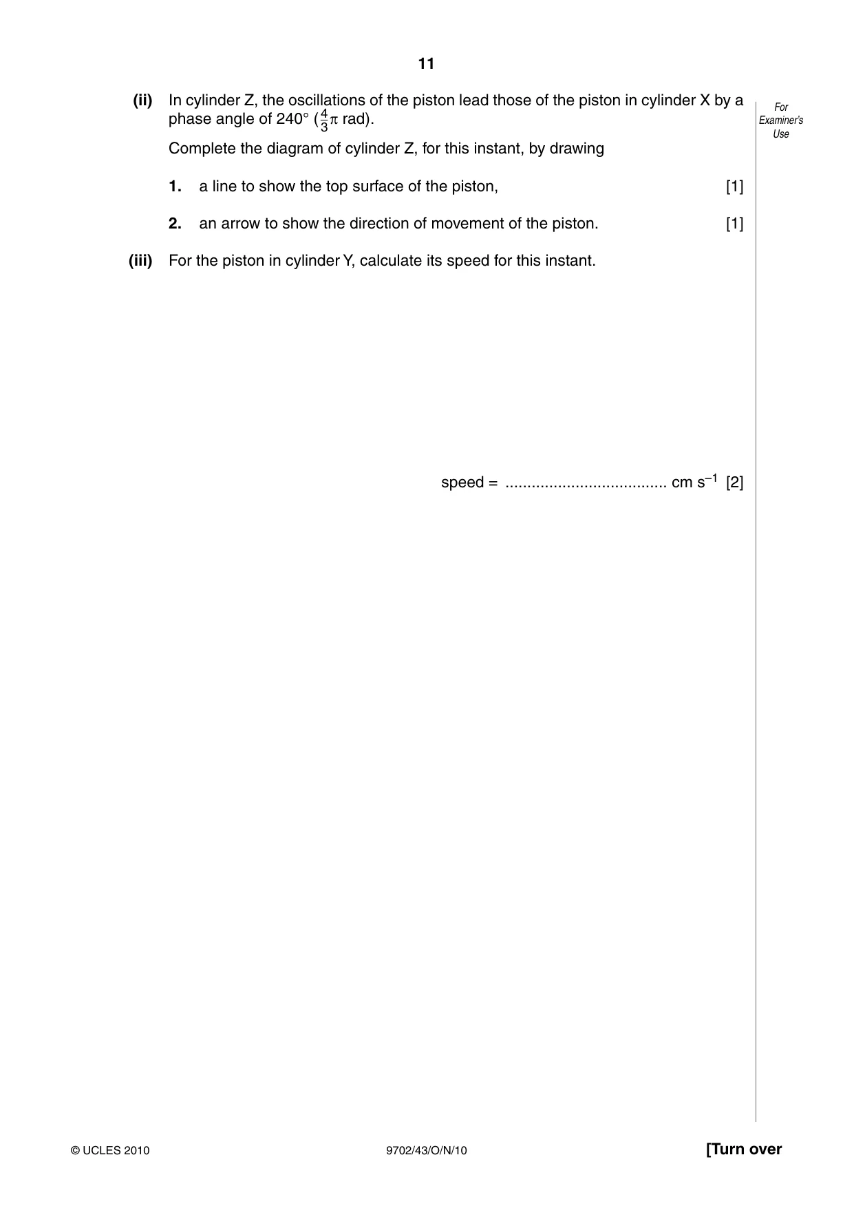
3 A cylinder and piston, used in a car engine, are illustrated in Fig. 3.1. For Examiner’s Use cylinder C D A B piston Fig. 3.1 The vertical motion of the piston in the cylinder is assumed to be simple harmonic. The top surface of the piston is at AB when it is at its lowest position; it is at CD when at its highest position, as marked in Fig. 3.1. (a) The displacement d of the piston may be represented by the equation d = – 4.0 cos(220t ) where d is measured in centimetres. (i) State the distance between the lowest position AB and the highest position CD of the top surface of the piston. distance = .......................................... cm [1] (ii) Determine the number of oscillations made per second by the piston. For Examiner’s Use number = ................................................ [2] (iii) On Fig. 3.1, draw a line to represent the top surface of the piston in the position where the speed of the piston is maximum. [1] (iv) Calculate the maximum speed of the piston. speed = ..................................... cm s–1 [2] (b) The engine of a car has several cylinders. Three of these cylinders are shown For in Fig. 3.2. Examiner’s Use X Y Z C D A B Fig. 3.2 X is the same cylinder and piston as in Fig. 3.1. Y and Z are two further cylinders, with the lowest and the highest positions of the top surface of each piston indicated. The pistons in the cylinders each have the same frequency of oscillation, but they are not in phase. At a particular instant in time, the position of the top of the piston in cylinder X is as shown. (i) In cylinder Y, the oscillations of the piston lead those of the piston in cylinder X by a phase angle of 120° (23p rad). Complete the diagram of cylinder Y, for this instant, by drawing 1. a line to show the top surface of the piston, [1] 2. an arrow to show the direction of movement of the piston. [1] (ii) In cylinder Z, the oscillations of the piston lead those of the piston in cylinder X by a For Examiner’s phase angle of 240° (43p rad). Use Complete the diagram of cylinder Z, for this instant, by drawing 1. a line to show the top surface of the piston, [1] 2. an arrow to show the direction of movement of the piston. [1] (iii) For the piston in cylinder Y, calculate its speed for this instant. speed = ..................................... cm s–1 [2]
Mark scheme: 3 (a) (i) 8.0 cm A1 [1] (ii) 2πf = 220 C1 f = 35 (condone unit) A1 [2] (iii) line drawn mid-way between AB and CD (allow ±2 mm) B1 [1] (iv) v = ωa C1 = 220 × 4.0 = 880 cm s–1 A1 [2] (b) (i) 1. line drawn 3 cm above AB (allow ±2 mm) B1 [1] 2. arrow pointing upwards B1 [1] (ii) 1. line drawn 3 cm above AB (allow ±2 mm) B1 [1] 2. arrow pointing downwards B1 [1] (iii) v = ω√(a2 – x2) = 220 × √(4.02 – 2.02) C1 = 760 cm s–1 A1 [2] (incorrect value for x, 0/2 marks)
Q4 · State what is meant by electric potential at a point
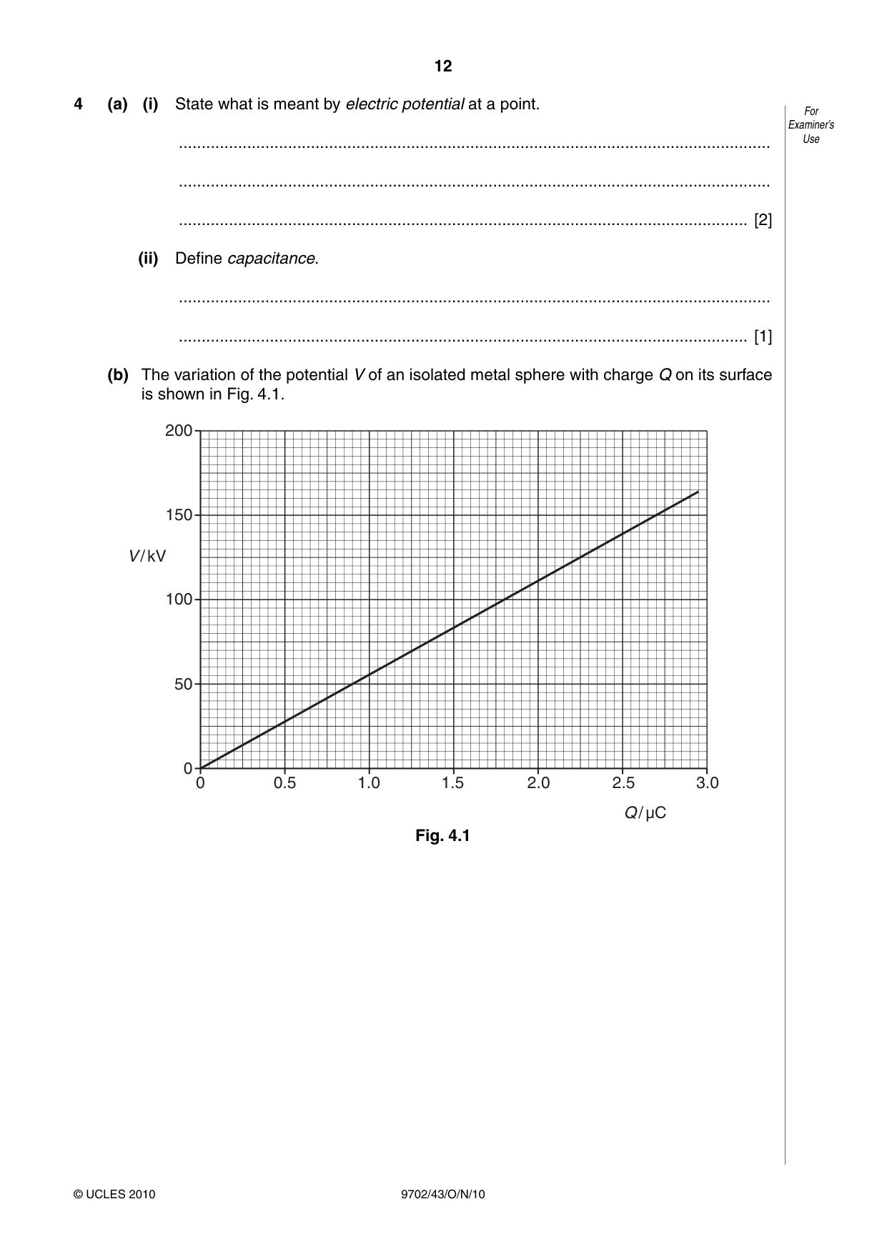
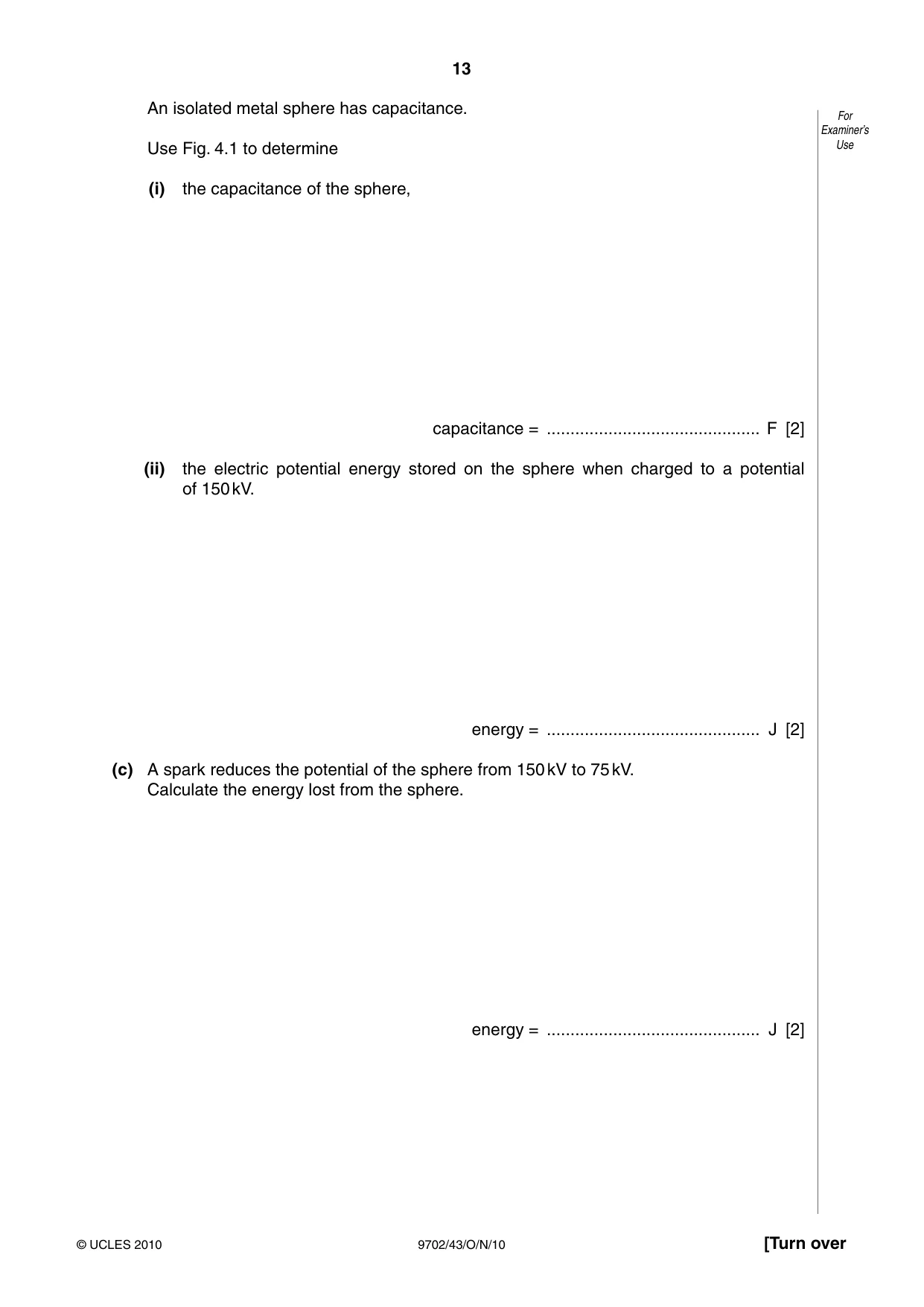
4 (a) (i) State what is meant by electric potential at a point. For Examiner’s .................................................................................................................................. Use .................................................................................................................................. ............................................................................................................................. [2] (ii) Define capacitance. .................................................................................................................................. ............................................................................................................................. [1] (b) The variation of the potential V of an isolated metal sphere with charge Q on its surface is shown in Fig. 4.1. 200 150 V / kV 100 50 0 0 0.5 1.0 1.5 2.0 2.5 3.0 Q / µC Fig. 4.1 An isolated metal sphere has capacitance. For Examiner’s Use Fig. 4.1 to determine Use (i) the capacitance of the sphere, capacitance = ............................................. F [2] (ii) the electric potential energy stored on the sphere when charged to a potential of 150 kV. energy = ............................................. J [2] (c) A spark reduces the potential of the sphere from 150 kV to 75 kV. Calculate the energy lost from the sphere. energy = ............................................. J [2]
Mark scheme: 4 (a) (i) work done moving unit positive charge M1 from infinity to the point A1 [2] (ii) charge / potential (difference) (ratio must be clear) B1 [1] (b) (i) capacitance = (2.7 × 10⁻⁶) / (150 × 103) C1 (allow any appropriate values) capacitance = 1.8 × 10⁻¹¹ (allow 1.8 ±0.05) A1 [2] (ii) either energy = ½CV 2 or energy = ½QV and Q = CV C1 energy = ½ × 1.8 × 10–11 × (150 × 103)2 or ½ × 2.7 × 10–6 × 150 × 103 = 0.20 J A1 [2] (c) either since energy ∝ V 2, capacitor has (½)2 of its energy left or full formula treatment C1 energy lost = 0.15 J A1 [2] GCE A LEVEL – October/November 2010 9702 43
Q5 · The poles of a horseshoe magnet measure 5.0 cm × 2.4 cm, as shown in Fig
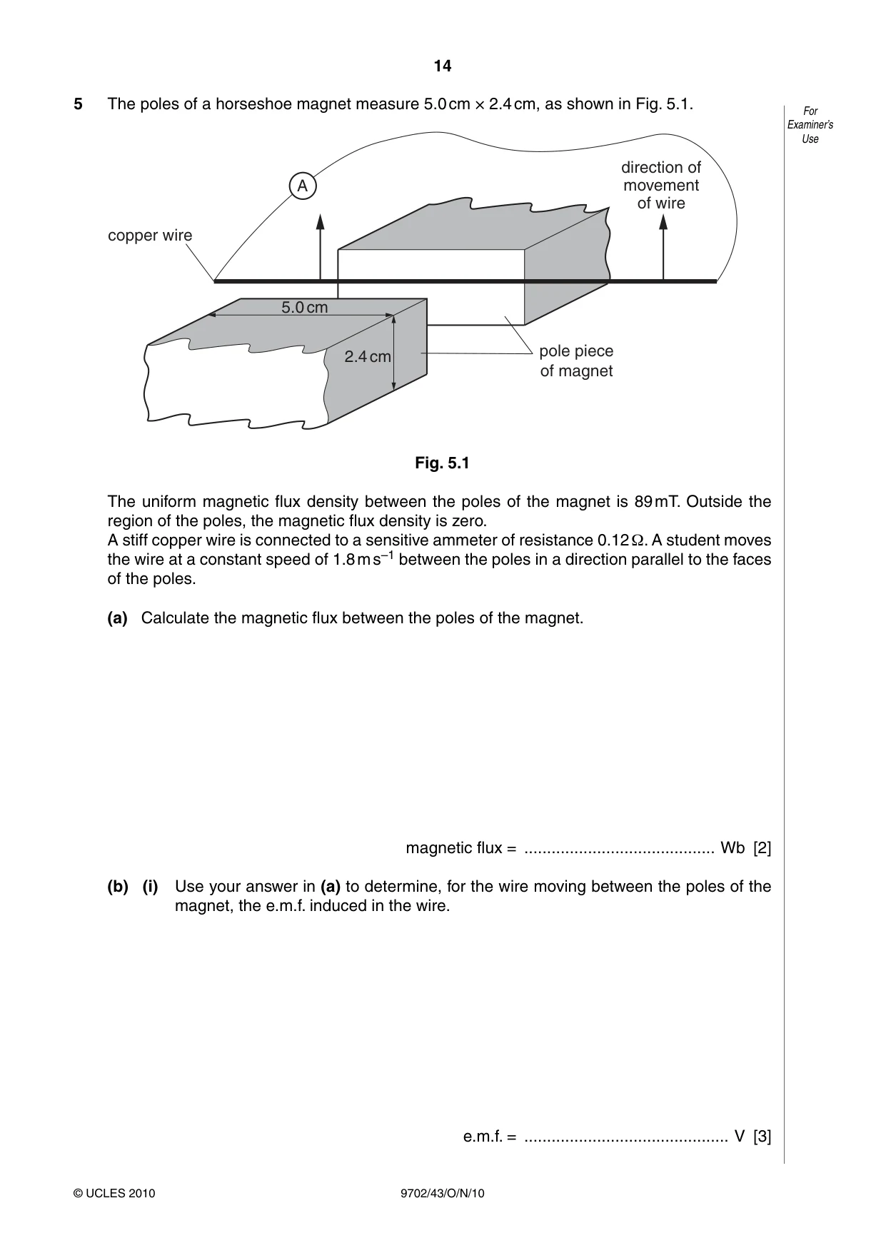
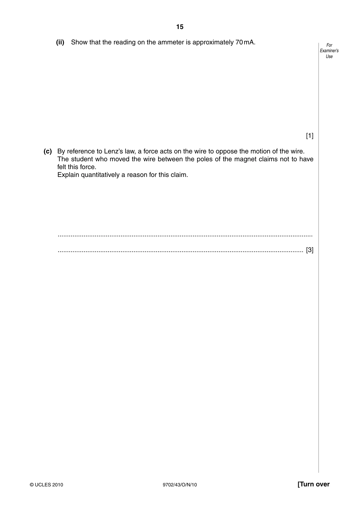
5 The poles of a horseshoe magnet measure 5.0 cm × 2.4 cm, as shown in Fig. 5.1. For Examiner’s Use direction of A movement of wire copper wire 5.0 cm pole piece 2.4 cm of magnet Fig. 5.1 The uniform magnetic flux density between the poles of the magnet is 89 mT. Outside the region of the poles, the magnetic flux density is zero. A stiff copper wire is connected to a sensitive ammeter of resistance 0.12 Ω. A student moves the wire at a constant speed of 1.8 m s–1 between the poles in a direction parallel to the faces of the poles. (a) Calculate the magnetic flux between the poles of the magnet. magnetic flux = .......................................... Wb [2] (b) (i) Use your answer in (a) to determine, for the wire moving between the poles of the magnet, the e.m.f. induced in the wire. e.m.f. = ............................................. V [3] (ii) Show that the reading on the ammeter is approximately 70 mA. For Examiner’s Use [1] (c) By reference to Lenz’s law, a force acts on the wire to oppose the motion of the wire. The student who moved the wire between the poles of the magnet claims not to have felt this force. Explain quantitatively a reason for this claim. .......................................................................................................................................... ..................................................................................................................................... [3]
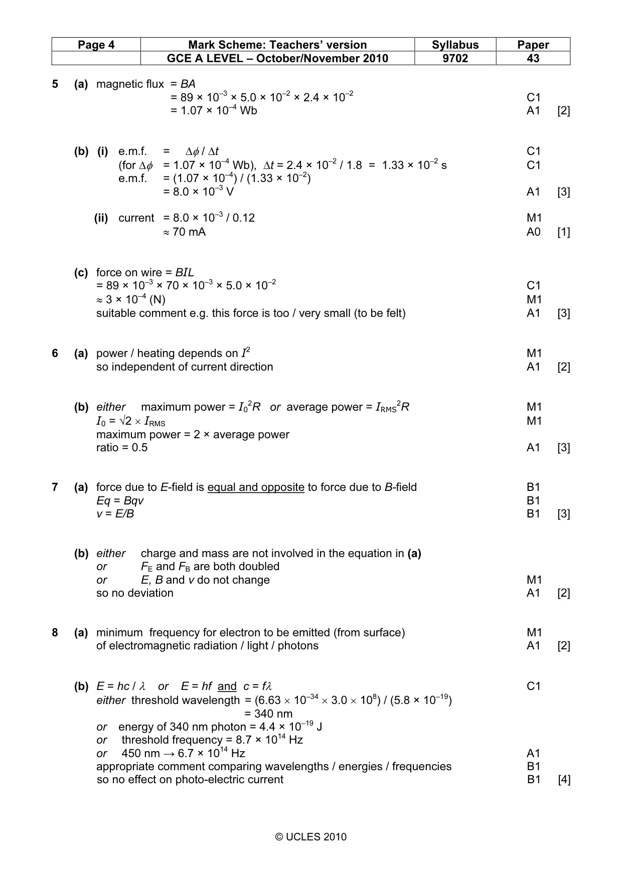
Mark scheme: 5 (a) magnetic flux = BA = 89 × 10–3 × 5.0 × 10–2 × 2.4 × 10–2 C1 = 1.07 × 10⁻⁴ Wb A1 [2] (b) (i) e.m.f. = ∆φ / ∆t C1 (for ∆φ = 1.07 × 10⁻⁴ Wb), ∆t = 2.4 × 10⁻² / 1.8 = 1.33 × 10⁻² s C1 e.m.f. = (1.07 × 10⁻⁴) / (1.33 × 10⁻²) = 8.0 × 10⁻³ V A1 [3] (ii) current = 8.0 × 10⁻³ / 0.12 M1 ≈ 70 mA A0 [1] (c) force on wire = BIL = 89 × 10–3 × 70 × 10–3 × 5.0 × 10–2 C1 ≈ 3 × 10⁻⁴ (N) M1 suitable comment e.g. this force is too / very small (to be felt) A1 [3] 2
Q6 · The variation with time t of the current I in a resistor is shown in Fig
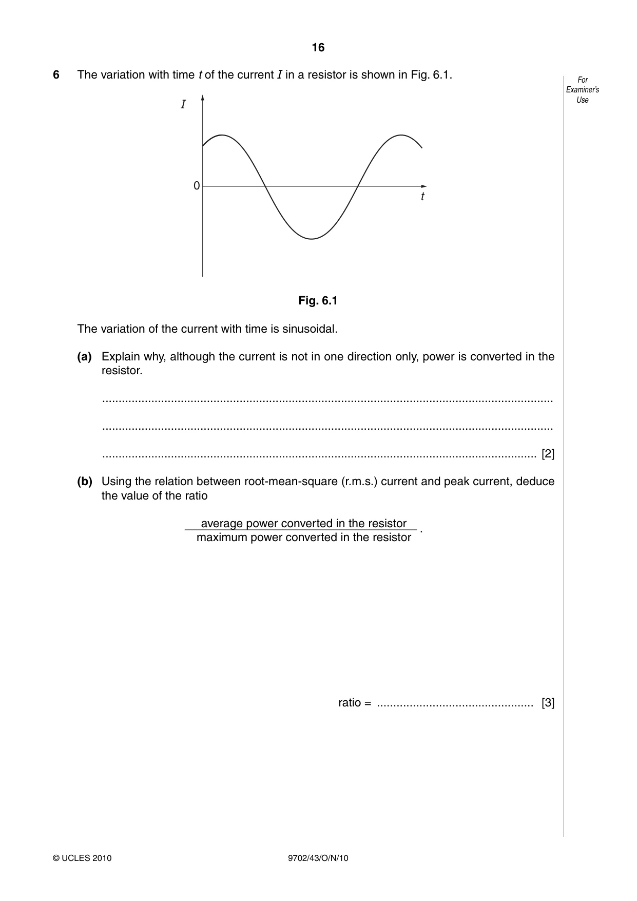
6 The variation with time t of the current I in a resistor is shown in Fig. 6.1. For Examiner’s I Use 0 t Fig. 6.1 The variation of the current with time is sinusoidal. (a) Explain why, although the current is not in one direction only, power is converted in the resistor. .......................................................................................................................................... .......................................................................................................................................... ..................................................................................................................................... [2] (b) Using the relation between root-mean-square (r.m.s.) current and peak current, deduce the value of the ratio average power converted in the resistore . maximum power converted in the resistor ratio = ................................................ [3]
Mark scheme: 6 (a) power / heating depends on I2 M1 so independent of current direction A1 [2] (b) either maximum power = I02R or average power = IRMS 2R M1 I0 = √2 × IRMS M1 maximum power = 2 × average power ratio = 0.5 A1 [3]
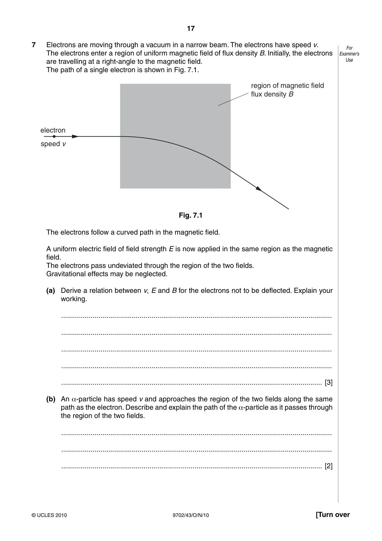
Q7 · Electrons are moving through a vacuum in a narrow beam
7 Electrons are moving through a vacuum in a narrow beam. The electrons have speed v. For The electrons enter a region of uniform magnetic field of flux density B. Initially, the electrons Examiner’s are travelling at a right-angle to the magnetic field. Use The path of a single electron is shown in Fig. 7.1. region of magnetic field flux density B electron speed v Fig. 7.1 The electrons follow a curved path in the magnetic field. A uniform electric field of field strength E is now applied in the same region as the magnetic field. The electrons pass undeviated through the region of the two fields. Gravitational effects may be neglected. (a) Derive a relation between v, E and B for the electrons not to be deflected. Explain your working. .......................................................................................................................................... .......................................................................................................................................... .......................................................................................................................................... .......................................................................................................................................... ..................................................................................................................................... [3] (b) An α-particle has speed v and approaches the region of the two fields along the same path as the electron. Describe and explain the path of the α-particle as it passes through the region of the two fields. .......................................................................................................................................... .......................................................................................................................................... ..................................................................................................................................... [2]
Mark scheme: 7 (a) force due to E-field is equal and opposite to force due to B-field B1 Eq = Bqv B1 v = E/B B1 [3] (b) either charge and mass are not involved in the equation in (a) or FE and FB are both doubled or E, B and v do not change M1 so no deviation A1 [2]
Q8 · By reference to the photoelectric effect, state what is meant by the threshold frequency
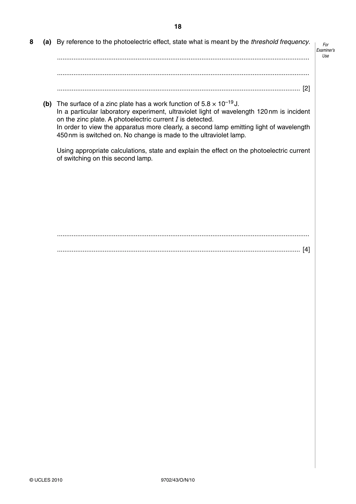
8 (a) By reference to the photoelectric effect, state what is meant by the threshold frequency. For Examiner’s .......................................................................................................................................... Use .......................................................................................................................................... ..................................................................................................................................... [2] (b) The surface of a zinc plate has a work function of 5.8 × 10⁻¹⁹ J. In a particular laboratory experiment, ultraviolet light of wavelength 120 nm is incident on the zinc plate. A photoelectric current I is detected. In order to view the apparatus more clearly, a second lamp emitting light of wavelength 450 nm is switched on. No change is made to the ultraviolet lamp. Using appropriate calculations, state and explain the effect on the photoelectric current of switching on this second lamp. .......................................................................................................................................... ..................................................................................................................................... [4]
Mark scheme: 8 (a) minimum frequency for electron to be emitted (from surface) M1 of electromagnetic radiation / light / photons A1 [2] (b) E = hc / λ or E = hf and c = fλ C1 either threshold wavelength = (6.63 × 10–34 × 3.0 × 108) / (5.8 × 10⁻¹⁹) = 340 nm or energy of 340 nm photon = 4.4 × 10⁻¹⁹ J or threshold frequency = 8.7 × 10¹⁴ Hz or 450 nm → 6.7 × 10¹⁴ Hz A1 appropriate comment comparing wavelengths / energies / frequencies B1 so no effect on photo-electric current B1 [4] GCE A LEVEL – October/November 2010 9702 43 Section B
Q9 · State, with reference to X-ray images, what is meant by sharpness
9 (a) (i) State, with reference to X-ray images, what is meant by sharpness. .................................................................................................................................. ..............................................................................................................................[1] (ii) Describe briefly two factors that affect the sharpness of an X-ray image. 1. ............................................................................................................................... .................................................................................................................................. 2. ............................................................................................................................... .................................................................................................................................. [3] (b) An X-ray image is taken of the skull of a patient. Another patient has a CT scan of his head. By reference to the formation of the image in each case, suggest why the exposure to radiation differs between the two imaging techniques. .......................................................................................................................................... .......................................................................................................................................... .......................................................................................................................................... .......................................................................................................................................... ......................................................................................................................................[4]
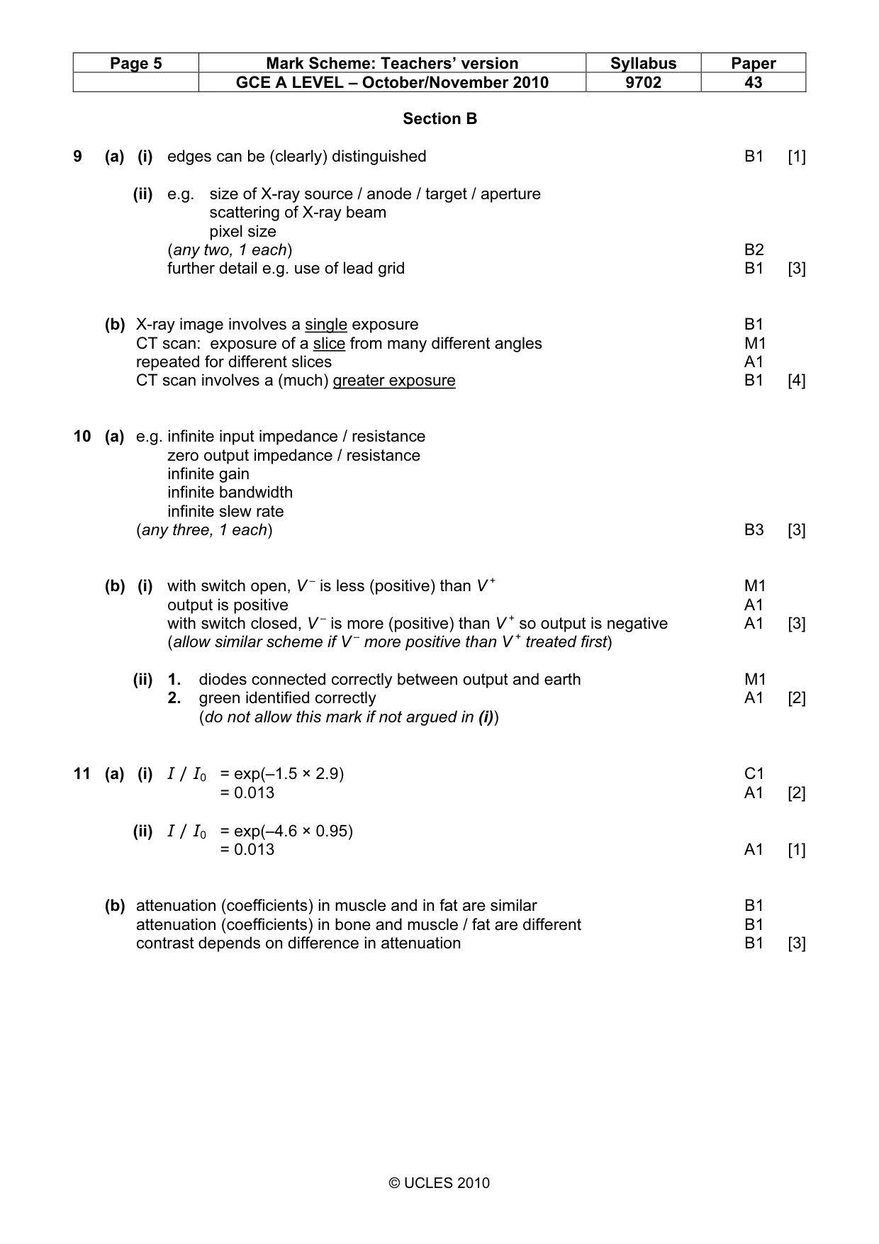
Mark scheme: 9 (a) (i) edges can be (clearly) distinguished B1 [1] (ii) e.g. size of X-ray source / anode / target / aperture scattering of X-ray beam pixel size (any two, 1 each) B2 further detail e.g. use of lead grid B1 [3] (b) X-ray image involves a single exposure B1 CT scan: exposure of a slice from many different angles M1 repeated for different slices A1 CT scan involves a (much) greater exposure B1 [4]
Q10 · State three properties of an ideal operational amplifier (op-amp)
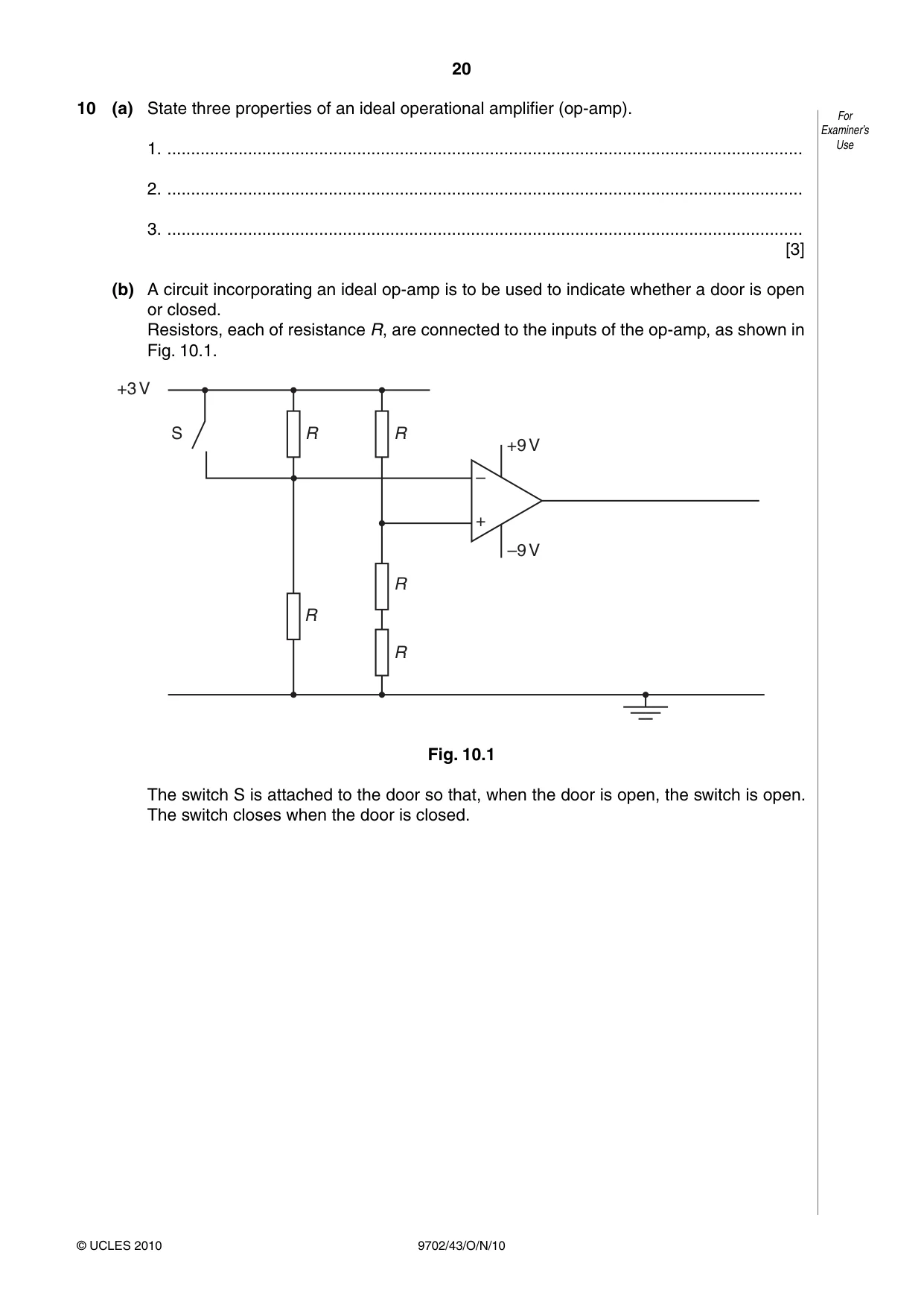
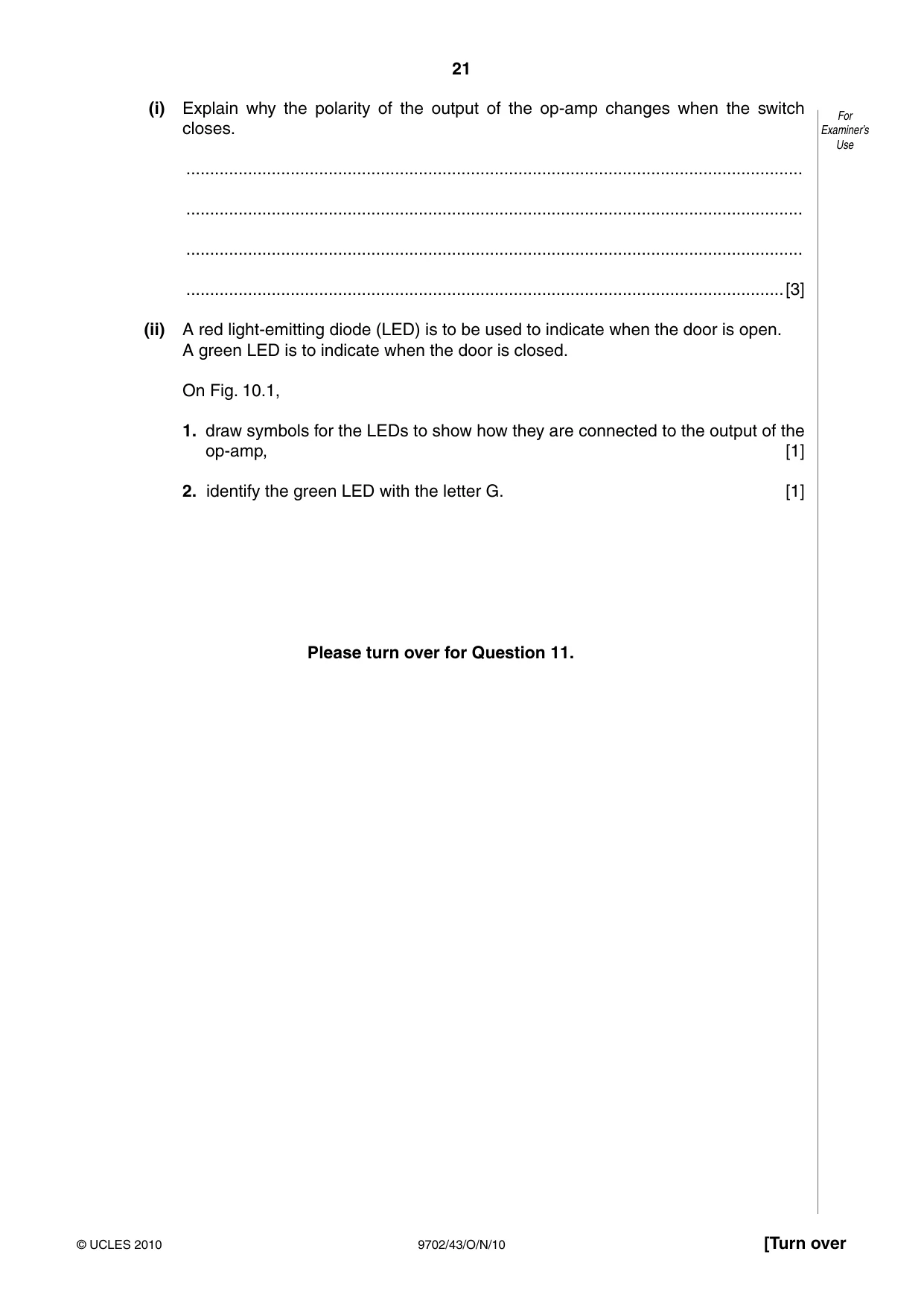
10 (a) State three properties of an ideal operational amplifier (op-amp). For Examiner’s 1. ...................................................................................................................................... Use 2. ...................................................................................................................................... 3. ...................................................................................................................................... [3] (b) A circuit incorporating an ideal op-amp is to be used to indicate whether a door is open or closed. Resistors, each of resistance R, are connected to the inputs of the op-amp, as shown in Fig. 10.1. +3 V S R R +9 V – + –9 V R R R Fig. 10.1 The switch S is attached to the door so that, when the door is open, the switch is open. The switch closes when the door is closed. (i) Explain why the polarity of the output of the op-amp changes when the switch For closes. Examiner’s Use .................................................................................................................................. .................................................................................................................................. .................................................................................................................................. ..............................................................................................................................[3] (ii) A red light-emitting diode (LED) is to be used to indicate when the door is open. A green LED is to indicate when the door is closed. On Fig. 10.1, 1. draw symbols for the LEDs to show how they are connected to the output of the op-amp, [1] 2. identify the green LED with the letter G. [1] Please turn over for Question 11.
Mark scheme: 10 (a) e.g. infinite input impedance / resistance zero output impedance / resistance infinite gain infinite bandwidth infinite slew rate (any three, 1 each) B3 [3] (b) (i) with switch open, V – is less (positive) than V + M1 output is positive A1 with switch closed, V – is more (positive) than V + so output is negative A1 [3] (allow similar scheme if V – more positive than V + treated first) (ii) 1. diodes connected correctly between output and earth M1 2. green identified correctly A1 [2] (do not allow this mark if not argued in (i))
Q11 · The linear attenuation (absorption) coefficient µ for X-ray radiation in bone, fat and…
11 The linear attenuation (absorption) coefficient µ for X-ray radiation in bone, fat and muscle is For given in Fig. 11.1. Examiner’s Use µ / cm–1 bone 2.9 fat 0.90 muscle 0.95 Fig. 11.1 (a) A parallel X-ray beam of intensity I0 is incident either on some bone or on some muscle. The emergent beam has intensity I. I Calculate the ratio for a thickness of I0 (i) 1.5 cm of bone, ratio = ................................................ [2] (ii) 4.6 cm of muscle. ratio = ................................................ [1] (b) Suggest why, on an X-ray plate, the contrast between bone and muscle is much greater than that between fat and muscle. .......................................................................................................................................... .......................................................................................................................................... .......................................................................................................................................... ......................................................................................................................................[3]
Mark scheme: 11 (a) (i) I / I0 = exp(–1.5 × 2.9) C1 = 0.013 A1 [2] (ii) I / I0 = exp(–4.6 × 0.95) = 0.013 A1 [1] (b) attenuation (coefficients) in muscle and in fat are similar B1 attenuation (coefficients) in bone and muscle / fat are different B1 contrast depends on difference in attenuation B1 [3] GCE A LEVEL – October/November 2010 9702 43
Q12 · Data may be transmitted as an analogue signal or as a digital signal
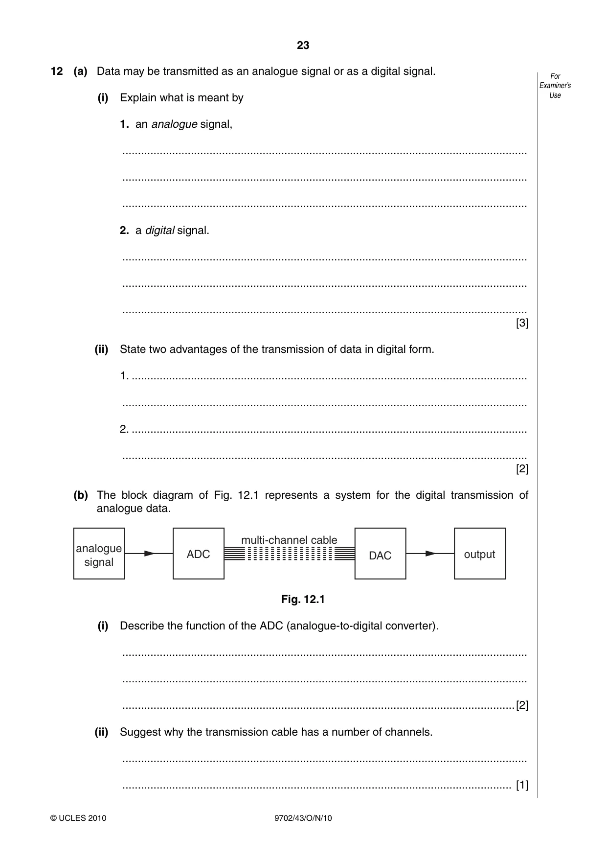
12 (a) Data may be transmitted as an analogue signal or as a digital signal. For Examiner’s (i) Explain what is meant by Use 1. an analogue signal, .................................................................................................................................. .................................................................................................................................. .................................................................................................................................. 2. a digital signal. .................................................................................................................................. .................................................................................................................................. .................................................................................................................................. [3] (ii) State two advantages of the transmission of data in digital form. 1. ............................................................................................................................... .................................................................................................................................. 2. ............................................................................................................................... .................................................................................................................................. [2] (b) The block diagram of Fig. 12.1 represents a system for the digital transmission of analogue data. multi-channel cable analogue ADC DAC output signal Fig. 12.1 (i) Describe the function of the ADC (analogue-to-digital converter). .................................................................................................................................. .................................................................................................................................. ..............................................................................................................................[2] (ii) Suggest why the transmission cable has a number of channels. .................................................................................................................................. ............................................................................................................................. [1]
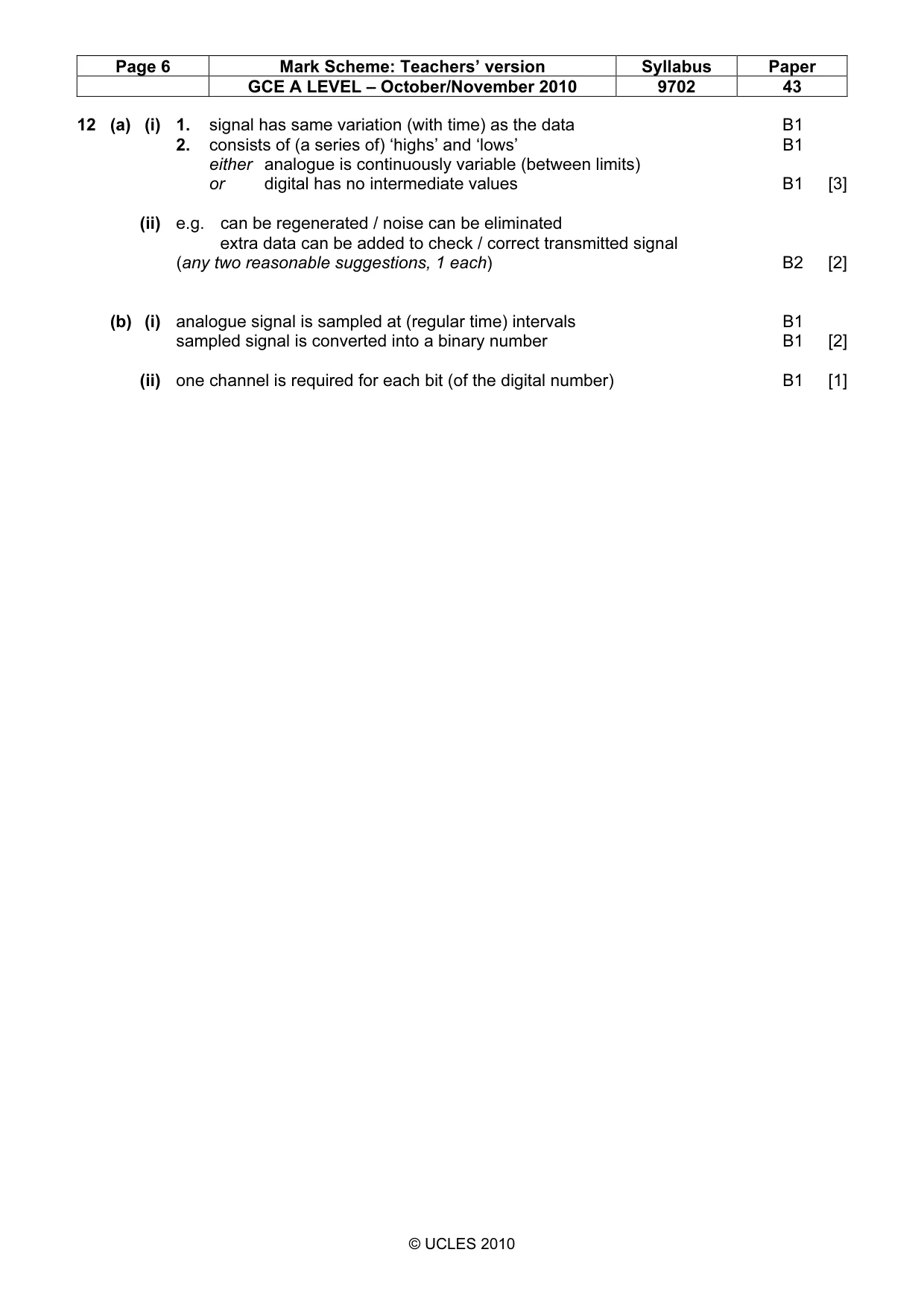
Mark scheme: 12 (a) (i) 1. signal has same variation (with time) as the data B1 2. consists of (a series of) ‘highs’ and ‘lows’ B1 either analogue is continuously variable (between limits) or digital has no intermediate values B1 [3] (ii) e.g. can be regenerated / noise can be eliminated extra data can be added to check / correct transmitted signal (any two reasonable suggestions, 1 each) B2 [2] (b) (i) analogue signal is sampled at (regular time) intervals B1 sampled signal is converted into a binary number B1 [2] (ii) one channel is required for each bit (of the digital number) B1 [1]
What was in this paper
The subtopics covered by these 12 questions, and how many questions each got. Open one in a new tab to see every Cambridge question on it.
What you needed in this session
Cambridge’s own grade thresholds for 2010 Oct/Nov, Paper 4 · Variant 3. A higher threshold means an easier paper — the bar moves with how the cohort did.