Cambridge A Level Physics 9702 — 2014 Oct/Nov Paper 4 · Variant 3
9702/43/O/N/14 · 13 questions · 100 marks · ≈113 min
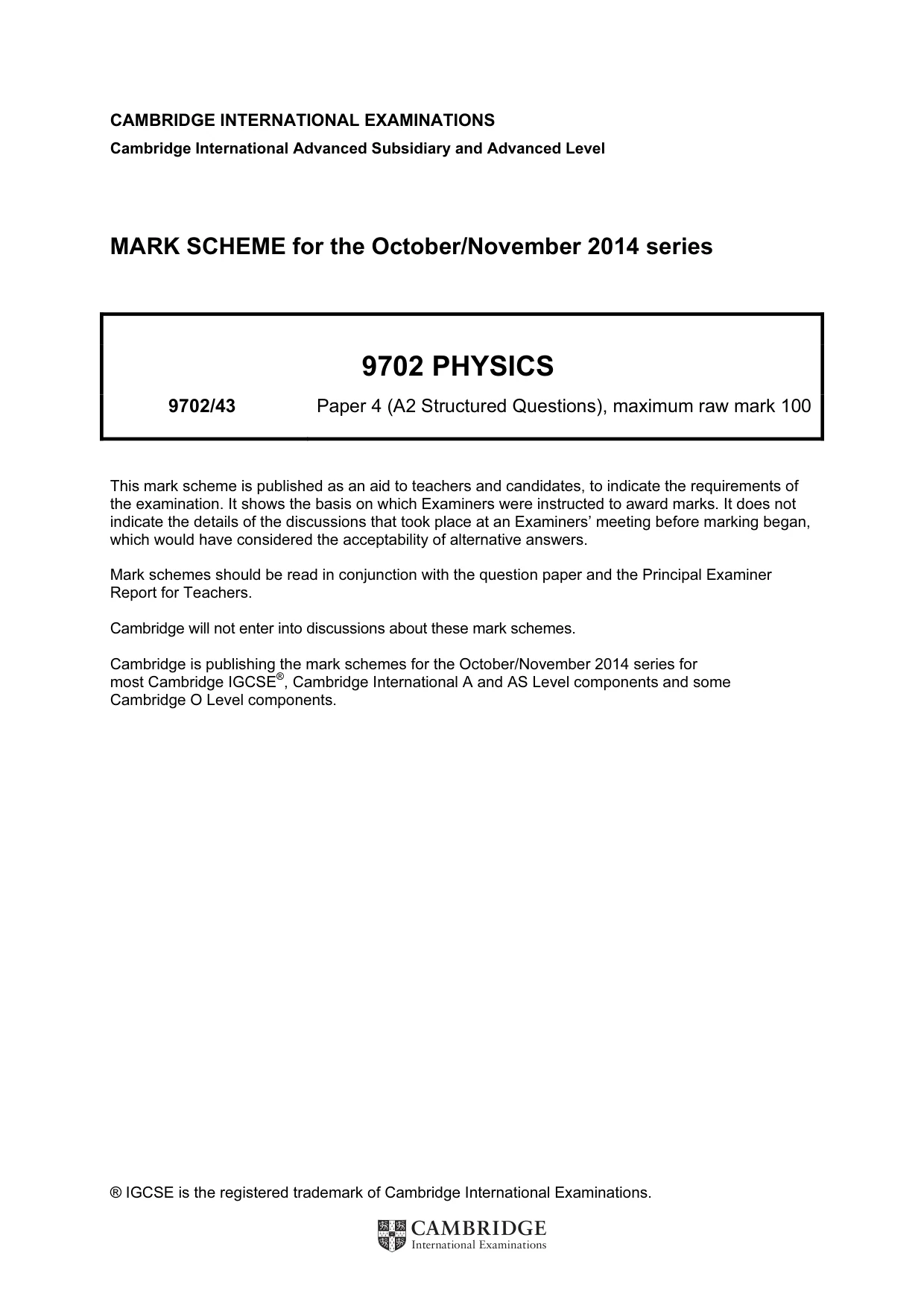
The question paper and its mark scheme, free to read here and free to download. This is Cambridge’s own paper, exactly as it was sat.
Question paper28 pages
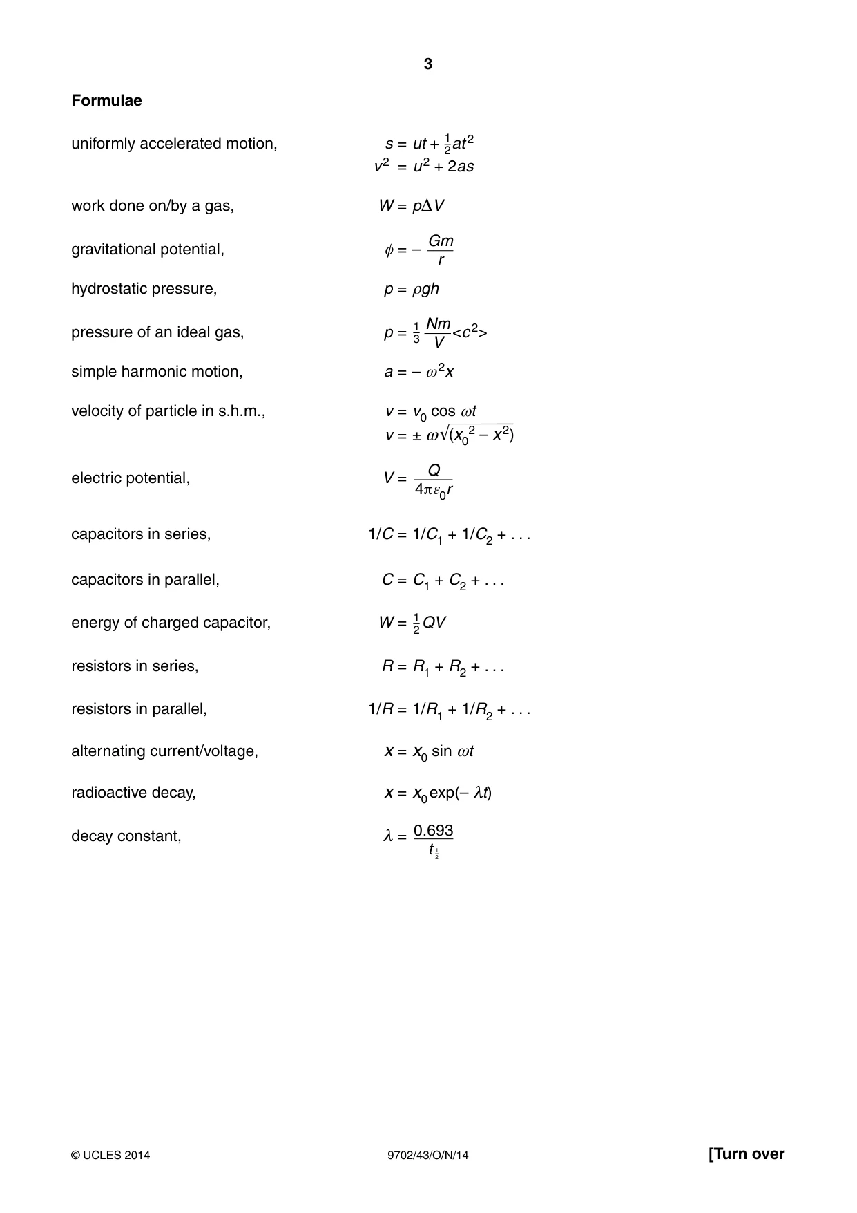




Mark scheme6 pages
Answers below. Sit the paper first if you are practising.
Questions as text
Q1 · A light spring is suspended from a fixed point
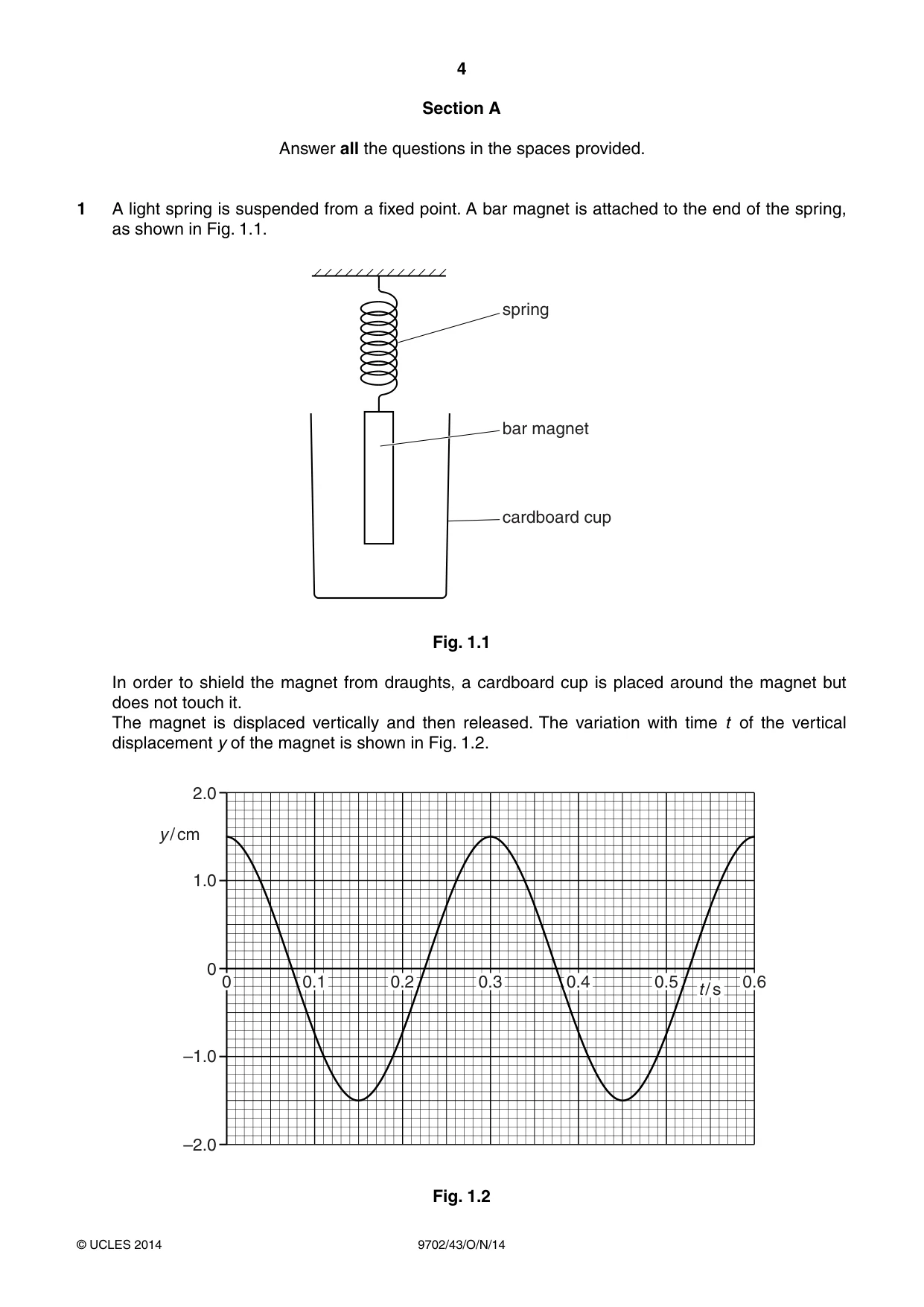
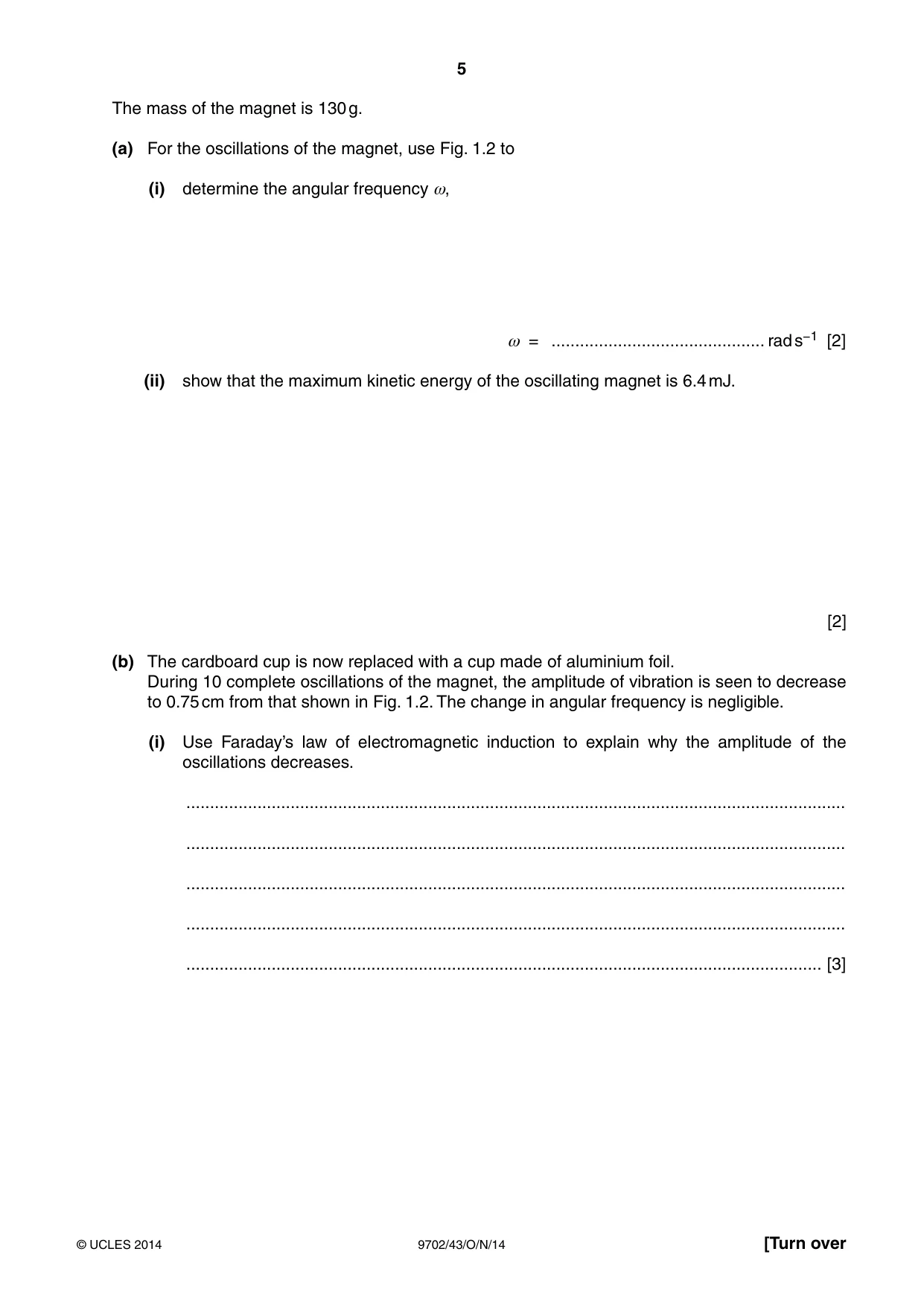
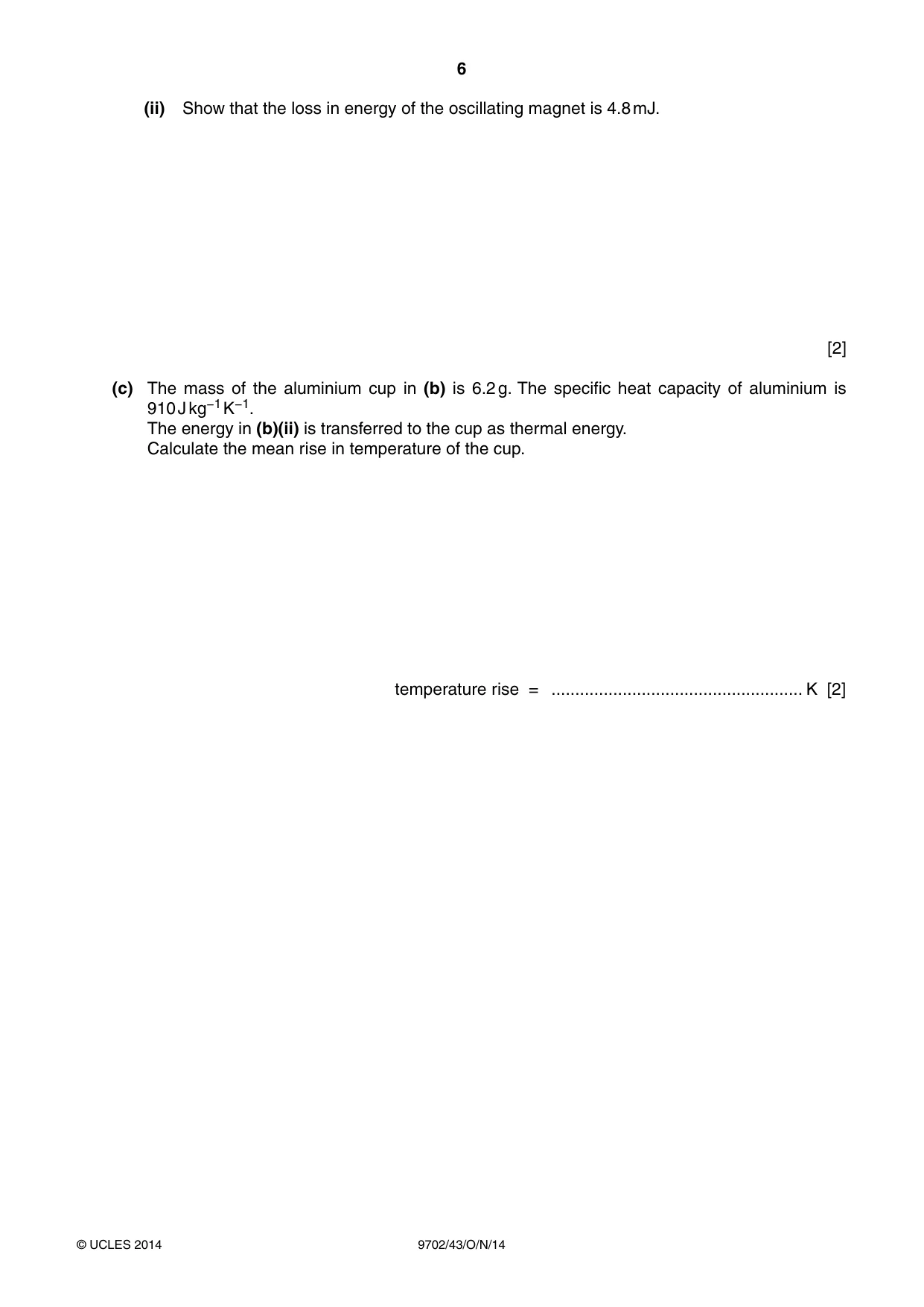
1 A light spring is suspended from a fixed point. A bar magnet is attached to the end of the spring, as shown in Fig. 1.1. spring bar magnet cardboard cup Fig. 1.1 In order to shield the magnet from draughts, a cardboard cup is placed around the magnet but does not touch it. The magnet is displaced vertically and then released. The variation with time t of the vertical displacement y of the magnet is shown in Fig. 1.2. 2.0 y / cm 1.0 0 0 0.1 0.2 0.3 0.4 0.5 0.6 t / s –1.0 –2.0 Fig. 1.2 The mass of the magnet is 130 g. (a) For the oscillations of the magnet, use Fig. 1.2 to (i) determine the angular frequency ω, ω = ............................................. rad s−1 [2] (ii) show that the maximum kinetic energy of the oscillating magnet is 6.4 mJ. [2] (b) The cardboard cup is now replaced with a cup made of aluminium foil. During 10 complete oscillations of the magnet, the amplitude of vibration is seen to decrease to 0.75 cm from that shown in Fig. 1.2. The change in angular frequency is negligible. (i) Use Faraday’s law of electromagnetic induction to explain why the amplitude of the oscillations decreases. ........................................................................................................................................... ........................................................................................................................................... ........................................................................................................................................... ........................................................................................................................................... ...................................................................................................................................... [3] (ii) Show that the loss in energy of the oscillating magnet is 4.8 mJ. [2] (c) The mass of the aluminium cup in (b) is 6.2 g. The specific heat capacity of aluminium is 910 J kg−1 K−1. The energy in (b)(ii) is transferred to the cup as thermal energy. Calculate the mean rise in temperature of the cup. temperature rise = ..................................................... K [2] Please turn over for Question 2.
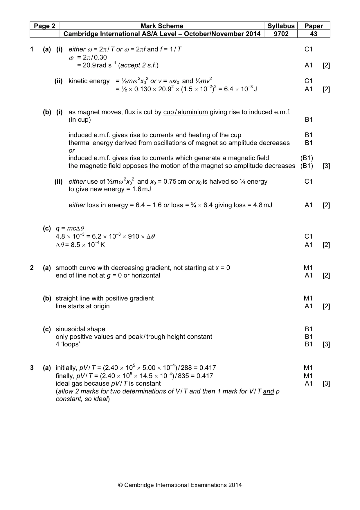
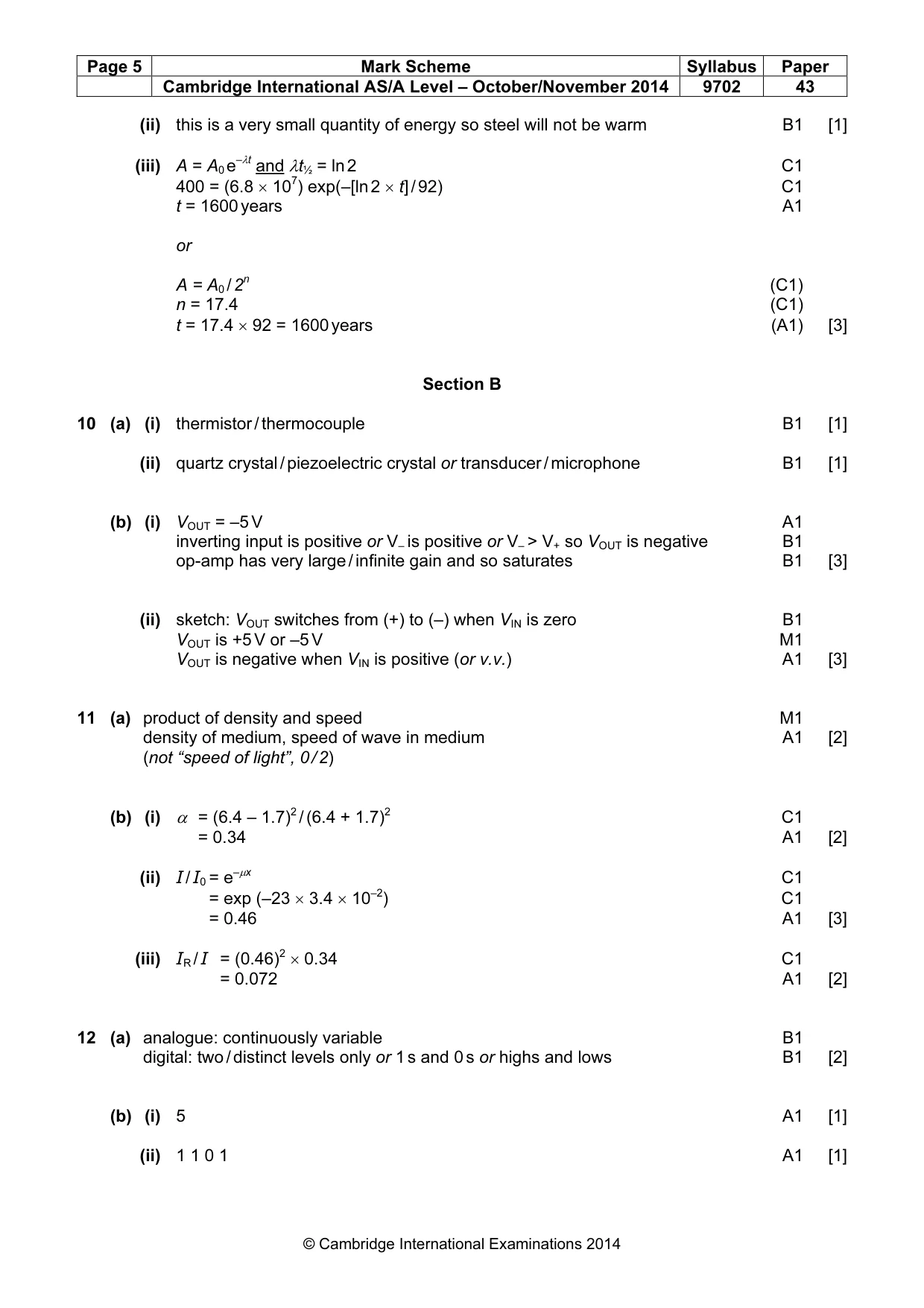
Mark scheme: 1 (a) (i) either ω = 2π / T or ω = 2πf and f = 1 / T C1 ω = 2π / 0.30 = 20.9 rad s–1 (accept 2 s.f.) A1 [2] (ii) kinetic energy = ½mω 2x02 or v = ωx0 and ½mv2 C1 = ½ × 0.130 × 20.92 × (1.5 × 10–2)2 = 6.4 × 10⁻³ J A1 [2] (b) (i) as magnet moves, flux is cut by cup / aluminium giving rise to induced e.m.f. (in cup) B1 induced e.m.f. gives rise to currents and heating of the cup B1 thermal energy derived from oscillations of magnet so amplitude decreases B1 or induced e.m.f. gives rise to currents which generate a magnetic field (B1) the magnetic field opposes the motion of the magnet so amplitude decreases (B1) [3] (ii) either use of ½mω 2x02 and x0 = 0.75 cm or x0 is halved so ¼ energy C1 to give new energy = 1.6 mJ either loss in energy = 6.4 – 1.6 or loss = ¾ × 6.4 giving loss = 4.8 mJ A1 [2] (c) q = mc∆θ 4.8 × 10–3 = 6.2 × 10–3 × 910 × ∆θ C1 ∆θ = 8.5 × 10⁻⁴ K A1 [2]
Q2 · On the axes of Fig
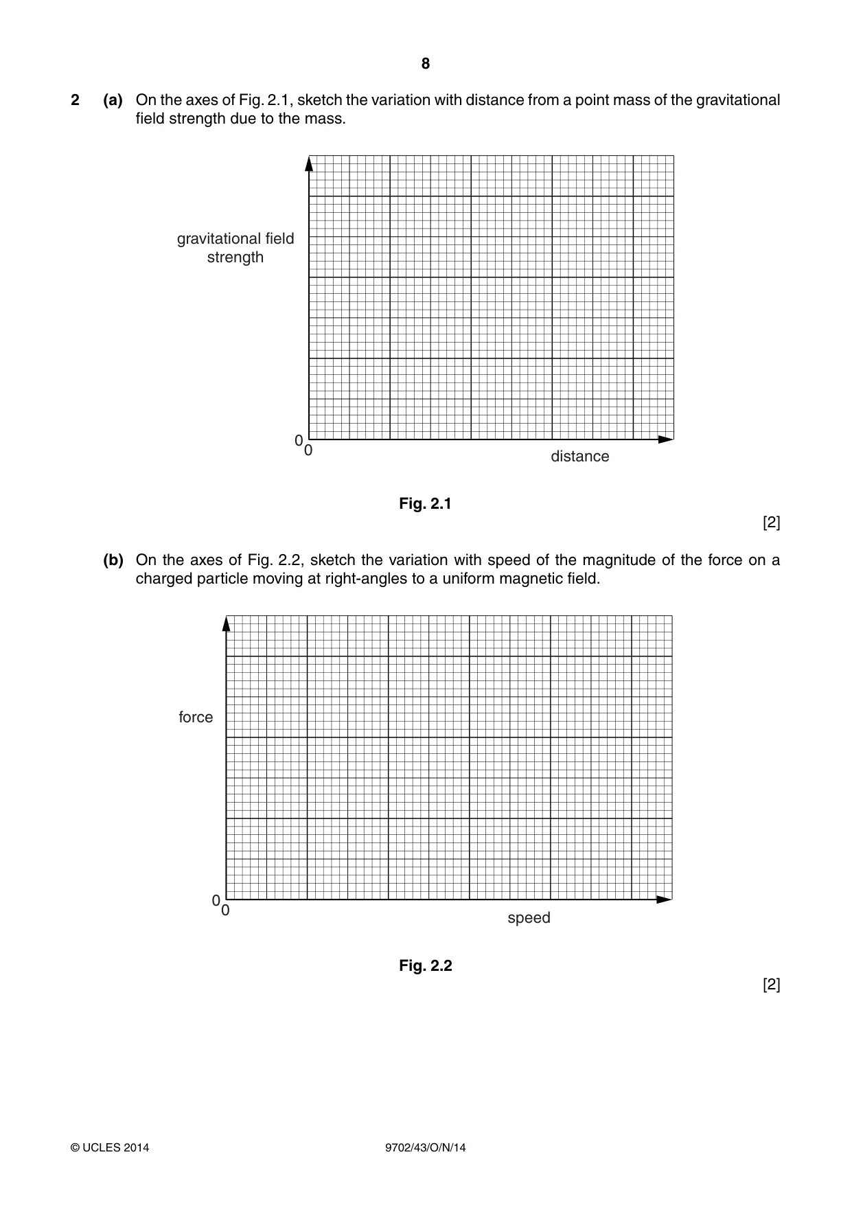
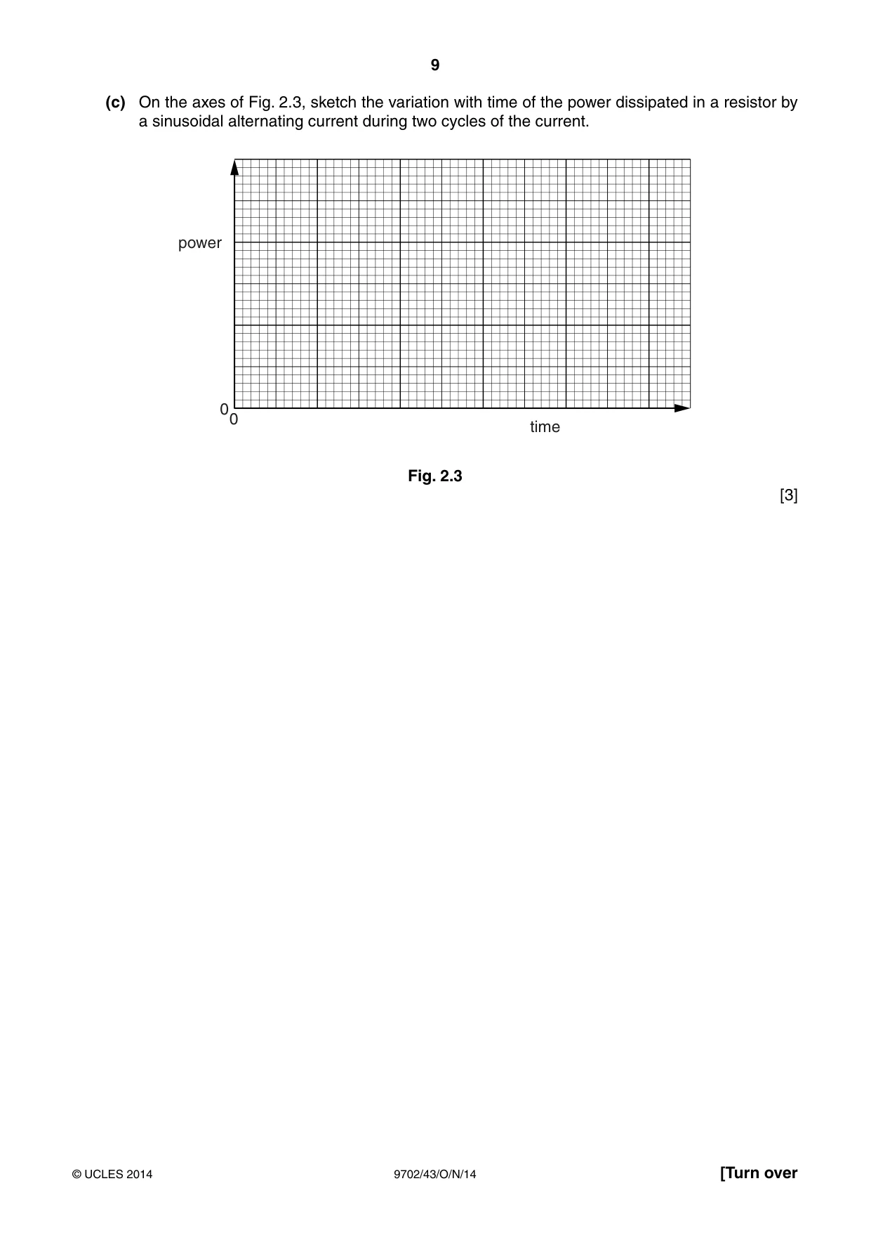
2 (a) On the axes of Fig. 2.1, sketch the variation with distance from a point mass of the gravitational field strength due to the mass. gravitational field strength 0 0 distance Fig. 2.1 [2] (b) On the axes of Fig. 2.2, sketch the variation with speed of the magnitude of the force on a charged particle moving at right-angles to a uniform magnetic field. force 0 0 speed Fig. 2.2 [2] (c) On the axes of Fig. 2.3, sketch the variation with time of the power dissipated in a resistor by a sinusoidal alternating current during two cycles of the current. power 0 0 time Fig. 2.3 [3]
Mark scheme: 2 (a) smooth curve with decreasing gradient, not starting at x = 0 M1 end of line not at g = 0 or horizontal A1 [2] (b) straight line with positive gradient M1 line starts at origin A1 [2] (c) sinusoidal shape B1 only positive values and peak / trough height constant B1 4 ‘loops’ B1 [3] 5 4
Q3 · A fixed mass of gas has an initial volume of 5.00 × 10⁻⁴ m3 at a pressure of 2.40 × 10⁵…
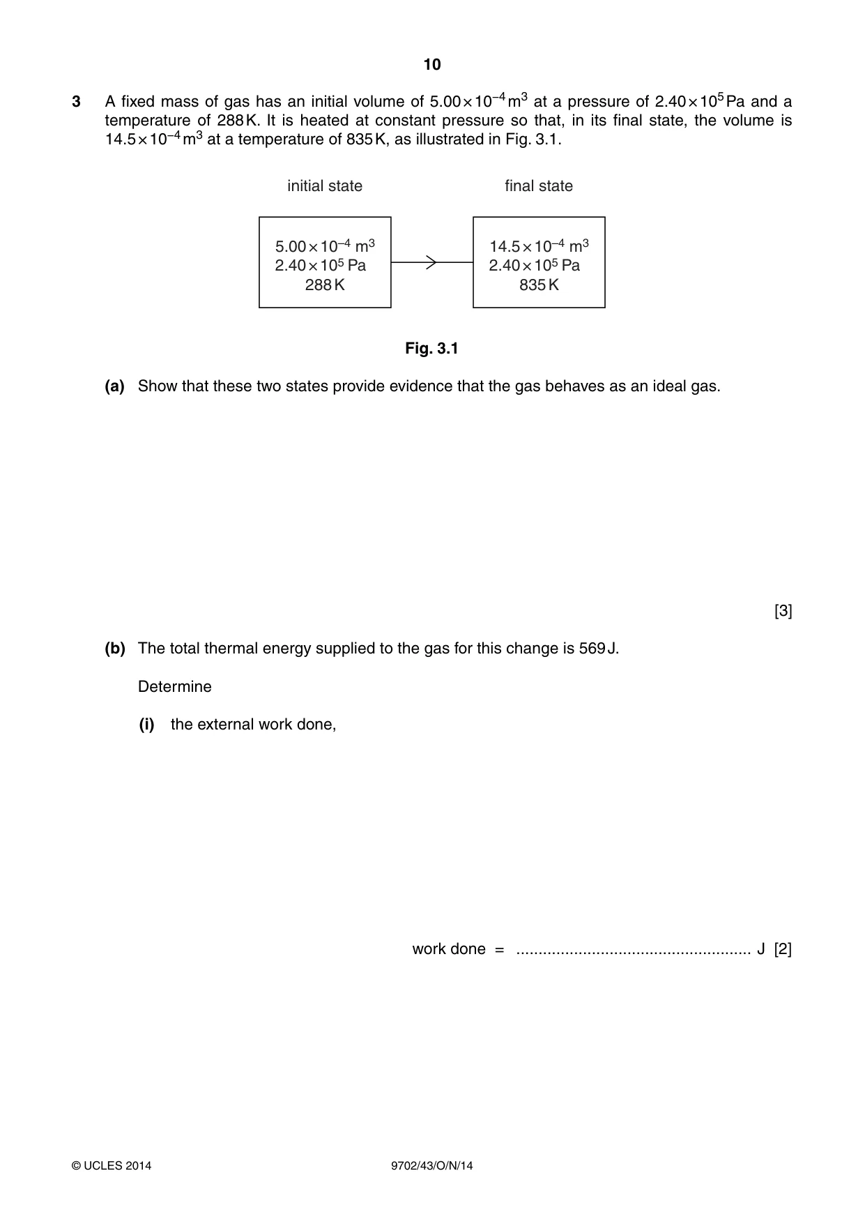
3 A fixed mass of gas has an initial volume of 5.00 × 10⁻⁴ m3 at a pressure of 2.40 × 10⁵ Pa and a temperature of 288 K. It is heated at constant pressure so that, in its final state, the volume is 14.5 × 10⁻⁴ m3 at a temperature of 835 K, as illustrated in Fig. 3.1. initial state final state 5.00 × 10⁻⁴ m3 14.5 × 10⁻⁴ m3 2.40 × 10⁵ Pa 2.40 × 10⁵ Pa 288 K 835 K Fig. 3.1 (a) Show that these two states provide evidence that the gas behaves as an ideal gas. [3] (b) The total thermal energy supplied to the gas for this change is 569 J. Determine (i) the external work done, work done = ..................................................... J [2] (ii) the change in internal energy of the gas. State whether the change is an increase or a decrease in internal energy. change in internal energy = ........................................................... J ........................................................................................................ [2]
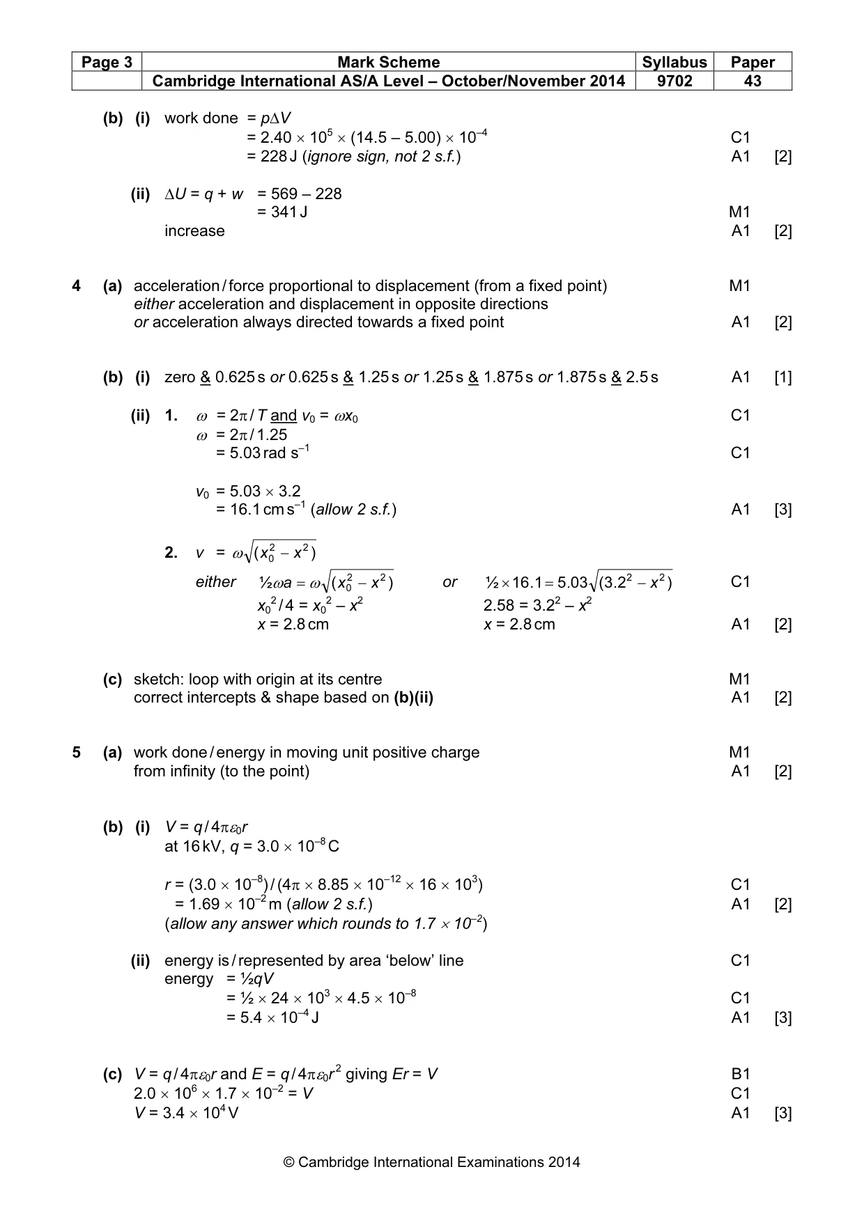
Mark scheme: 3 (a) initially, pV / T = (2.40 × 105 × 5.00 × 10–4) / 288 = 0.417 M1 finally, pV / T = (2.40 × 105 × 14.5 × 10–4) / 835 = 0.417 M1 ideal gas because pV / T is constant A1 [3] (allow 2 marks for two determinations of V / T and then 1 mark for V / T and p constant, so ideal) (b) (i) work done = p∆V = 2.40 × 105 × (14.5 – 5.00) × 10–4 C1 = 228 J (ignore sign, not 2 s.f.) A1 [2] (ii) ∆U = q + w = 569 – 228 = 341 J M1 increase A1 [2]
Q4 · State what is meant by simple harmonic motion
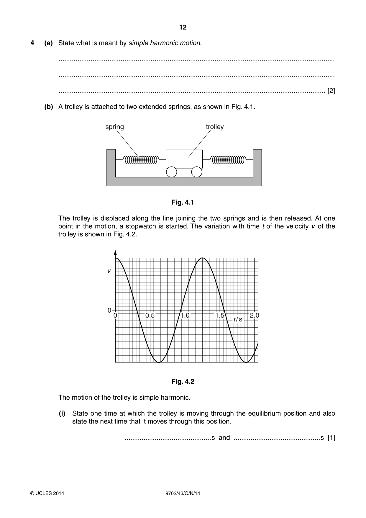
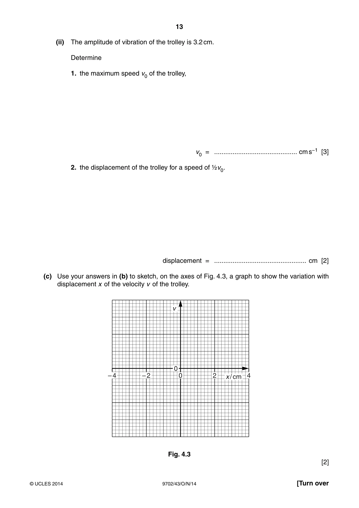
4 (a) State what is meant by simple harmonic motion. ................................................................................................................................................... ................................................................................................................................................... .............................................................................................................................................. [2] (b) A trolley is attached to two extended springs, as shown in Fig. 4.1. spring trolley Fig. 4.1 The trolley is displaced along the line joining the two springs and is then released. At one point in the motion, a stopwatch is started. The variation with time t of the velocity v of the trolley is shown in Fig. 4.2. v 0 0 0.5 1.0 1.5 2.0 tt // ss Fig. 4.2 The motion of the trolley is simple harmonic. (i) State one time at which the trolley is moving through the equilibrium position and also state the next time that it moves through this position. .............................................. s and .............................................. s [1] (ii) The amplitude of vibration of the trolley is 3.2 cm. Determine 1. the maximum speed v0 of the trolley, v0 = ............................................. cm s−1 [3] 2. the displacement of the trolley for a speed of ½v0. displacement = .................................................. cm [2] (c) Use your answers in (b) to sketch, on the axes of Fig. 4.3, a graph to show the variation with displacement x of the velocity v of the trolley. v 0 – 4 – 2 0 2 x / cm 4 Fig. 4.3 [2]
Mark scheme: 4 (a) acceleration / force proportional to displacement (from a fixed point) M1 either acceleration and displacement in opposite directions or acceleration always directed towards a fixed point A1 [2] (b) (i) zero & 0.625 s or 0.625 s & 1.25 s or 1.25 s & 1.875 s or 1.875 s & 2.5 s A1 [1] (ii) 1. ω = 2π / T and v0 = ωx0 C1 ω = 2π / 1.25 = 5.03 rad s–1 C1 v0 = 5.03 × 3.2 = 16.1 cm s–1 (allow 2 s.f.) A1 [3] 2. v = ω ( x 02 − x 2 ) either ½ω a = ω ( x 02 − x 2 ) or ½ × 16 . 1 = 5 . 03 ( 3 . 2 2 − x 2 ) C1 x02 / 4 = x02 – x2 2.58 = 3.22 – x2 x = 2.8 cm x = 2.8 cm A1 [2] (c) sketch: loop with origin at its centre M1 correct intercepts & shape based on (b)(ii) A1 [2]
Q5 · Define electric potential at a point
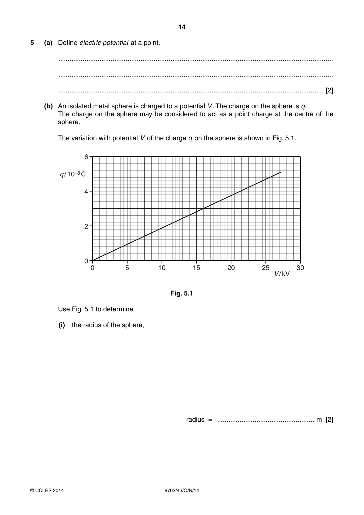
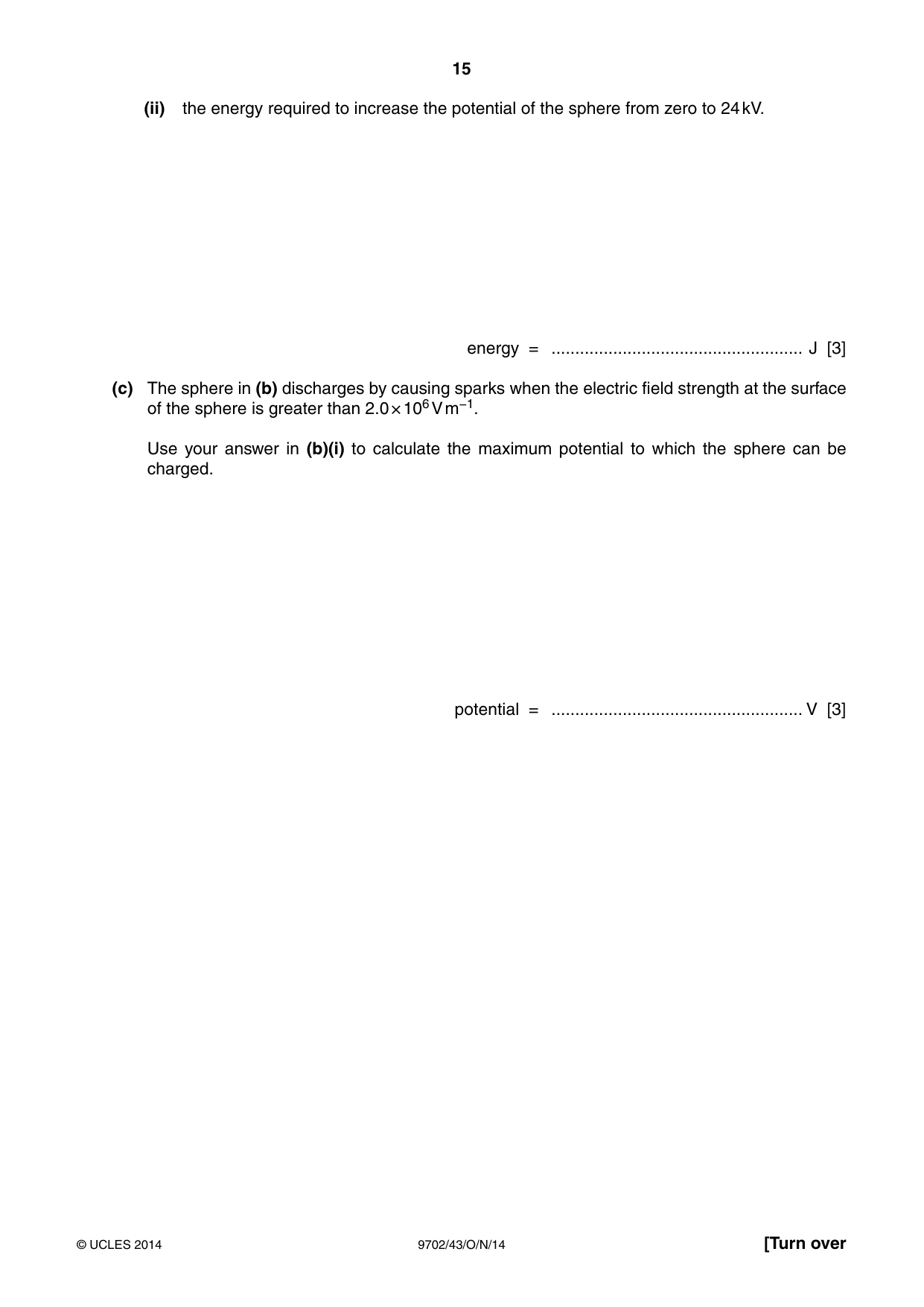
5 (a) Define electric potential at a point. ................................................................................................................................................... ................................................................................................................................................... .............................................................................................................................................. [2] (b) An isolated metal sphere is charged to a potential V . The charge on the sphere is q. The charge on the sphere may be considered to act as a point charge at the centre of the sphere. The variation with potential V of the charge q on the sphere is shown in Fig. 5.1. 6 q / 10–8 C 4 2 0 0 5 10 15 20 25 30 V / kV Fig. 5.1 Use Fig. 5.1 to determine (i) the radius of the sphere, radius = .................................................... m [2] (ii) the energy required to increase the potential of the sphere from zero to 24 kV. energy = ..................................................... J [3] (c) The sphere in (b) discharges by causing sparks when the electric field strength at the surface of the sphere is greater than 2.0 × 10⁶ V m−1. Use your answer in (b)(i) to calculate the maximum potential to which the sphere can be charged. potential = ..................................................... V [3]
Mark scheme: 5 (a) work done / energy in moving unit positive charge M1 from infinity (to the point) A1 [2] (b) (i) V = q / 4πε0r at 16 kV, q = 3.0 × 10⁻⁸ C r = (3.0 × 10⁻⁸) / (4π × 8.85 × 10–12 × 16 × 103) C1 = 1.69 × 10⁻² m (allow 2 s.f.) A1 [2] (allow any answer which rounds to 1.7 × 10⁻²) (ii) energy is / represented by area ‘below’ line C1 energy = ½qV = ½ × 24 × 103 × 4.5 × 10–8 C1 = 5.4 × 10⁻⁴ J A1 [3] (c) V = q / 4πε0r and E = q / 4πε0r 2 giving Er = V B1 2.0 × 106 × 1.7 × 10–2 = V C1 V = 3.4 × 10⁴ V A1 [3]
Q6 · Three capacitors, each of capacitance 48 μF, are connected as shown in Fig
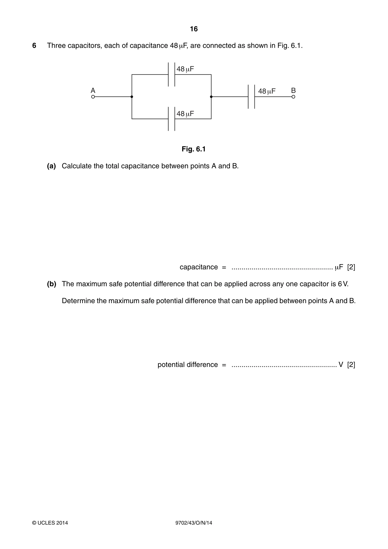
6 Three capacitors, each of capacitance 48 μF, are connected as shown in Fig. 6.1. 48 +F A 48 +F B 48 +F Fig. 6.1 (a) Calculate the total capacitance between points A and B. capacitance = ................................................... μF [2] (b) The maximum safe potential difference that can be applied across any one capacitor is 6 V. Determine the maximum safe potential difference that can be applied between points A and B. potential difference = ..................................................... V [2]
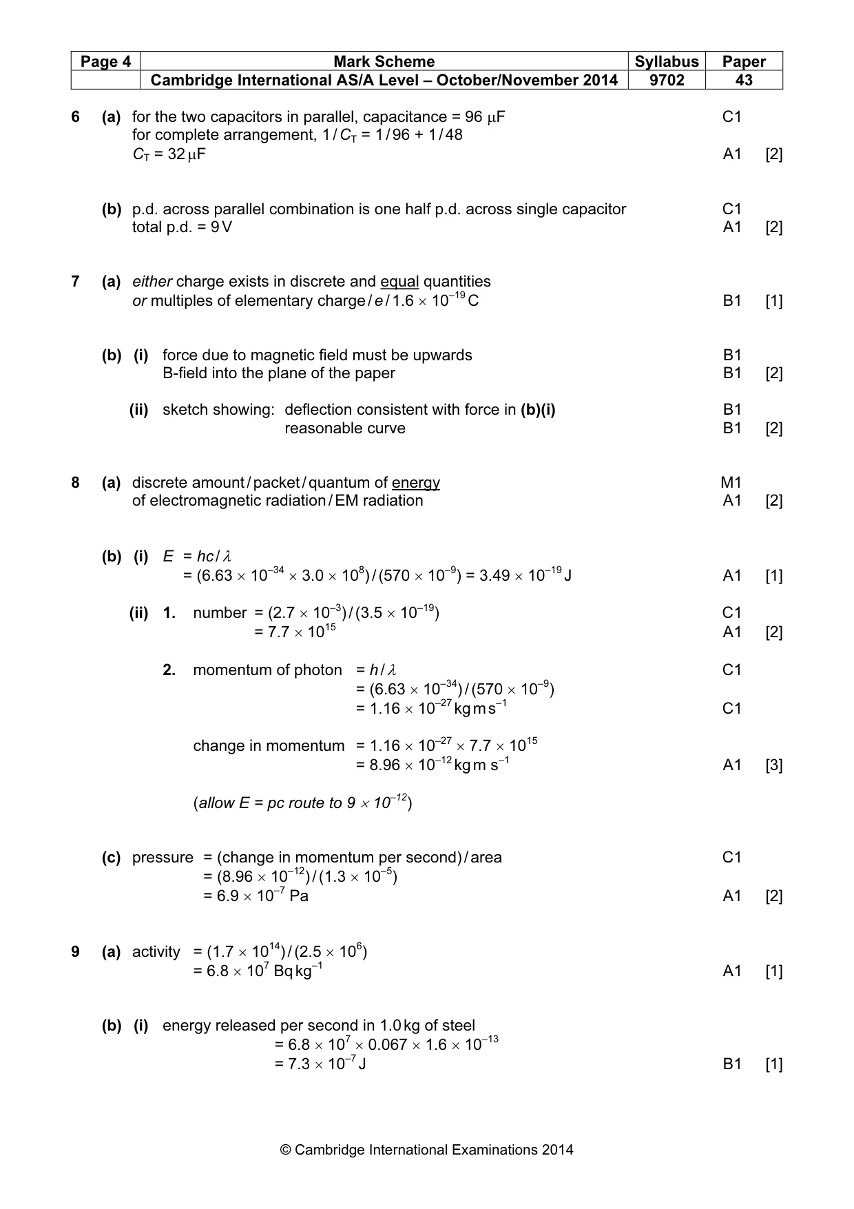
Mark scheme: 6 (a) for the two capacitors in parallel, capacitance = 96 µF C1 for complete arrangement, 1 / CT = 1 / 96 + 1 / 48 CT = 32 µF A1 [2] (b) p.d. across parallel combination is one half p.d. across single capacitor C1 total p.d. = 9 V A1 [2]
Q7 · State what is meant by quantisation of charge
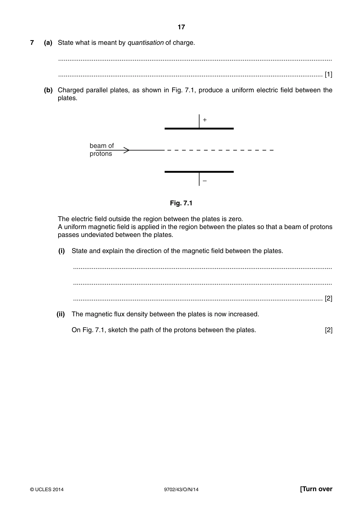
7 (a) State what is meant by quantisation of charge. ................................................................................................................................................... .............................................................................................................................................. [1] (b) Charged parallel plates, as shown in Fig. 7.1, produce a uniform electric field between the plates. + beam of protons – Fig. 7.1 The electric field outside the region between the plates is zero. A uniform magnetic field is applied in the region between the plates so that a beam of protons passes undeviated between the plates. (i) State and explain the direction of the magnetic field between the plates. ........................................................................................................................................... ........................................................................................................................................... ...................................................................................................................................... [2] (ii) The magnetic flux density between the plates is now increased. On Fig. 7.1, sketch the path of the protons between the plates. [2]
Mark scheme: 7 (a) either charge exists in discrete and equal quantities or multiples of elementary charge / e / 1.6 × 10⁻¹⁹ C B1 [1] (b) (i) force due to magnetic field must be upwards B1 B-field into the plane of the paper B1 [2] (ii) sketch showing: deflection consistent with force in (b)(i) B1 reasonable curve B1 [2]
Q8 · State what is meant by a photon
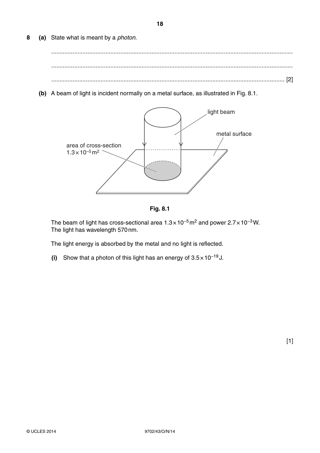
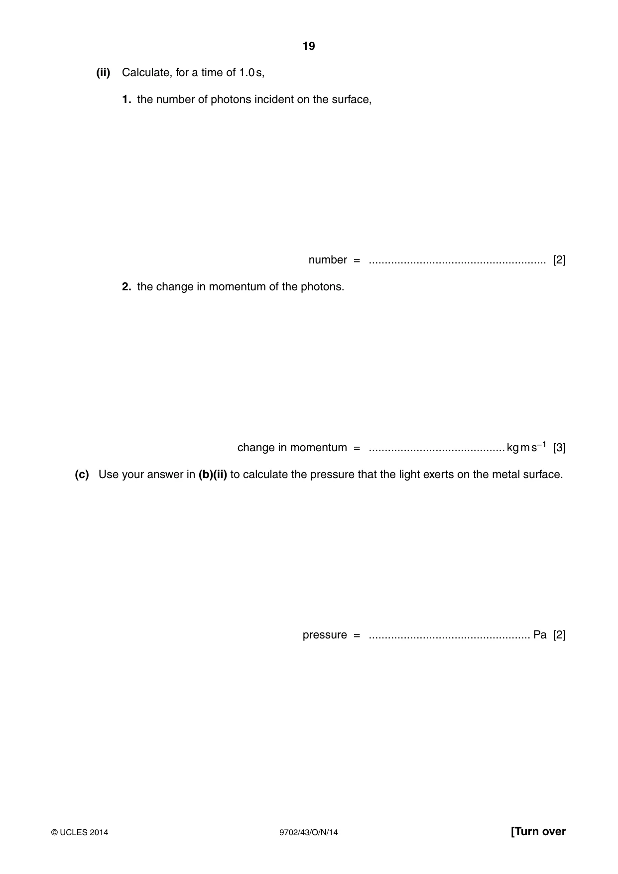
8 (a) State what is meant by a photon. ................................................................................................................................................... ................................................................................................................................................... .............................................................................................................................................. [2] (b) A beam of light is incident normally on a metal surface, as illustrated in Fig. 8.1. light beam metal surface area of cross-section 1.3 × 10⁻⁵ m2 Fig. 8.1 The beam of light has cross-sectional area 1.3 × 10⁻⁵ m2 and power 2.7 × 10⁻³ W. The light has wavelength 570 nm. The light energy is absorbed by the metal and no light is reflected. (i) Show that a photon of this light has an energy of 3.5 × 10⁻¹⁹ J. [1] (ii) Calculate, for a time of 1.0 s, 1. the number of photons incident on the surface, number = ........................................................ [2] 2. the change in momentum of the photons. change in momentum = ........................................... kg m s−1 [3] (c) Use your answer in (b)(ii) to calculate the pressure that the light exerts on the metal surface. pressure = ................................................... Pa [2]
Mark scheme: 8 (a) discrete amount / packet / quantum of energy M1 of electromagnetic radiation / EM radiation A1 [2] (b) (i) E = hc / λ = (6.63 × 10–34 × 3.0 × 108) / (570 × 10–9) = 3.49 × 10⁻¹⁹ J A1 [1] (ii) 1. number = (2.7 × 10⁻³) / (3.5 × 10⁻¹⁹) C1 = 7.7 × 10¹⁵ A1 [2] 2. momentum of photon = h / λ C1 = (6.63 × 10⁻³⁴) / (570 × 10–9) = 1.16 × 10⁻²⁷ kg m s–1 C1 change in momentum = 1.16 × 10–27 × 7.7 × 1015 = 8.96 × 10⁻¹² kg m s–1 A1 [3] (allow E = pc route to 9 × 10–12) (c) pressure = (change in momentum per second) / area C1 = (8.96 × 10⁻¹²) / (1.3 × 10⁻⁵) = 6.9 × 10⁻⁷ Pa A1 [2] 14 6
Q9 · During the de-commissioning of a nuclear reactor, a mass of 2.5 × 10⁶ kg of steel is…
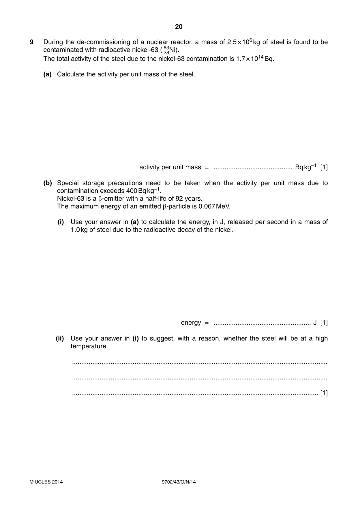
9 During the de-commissioning of a nuclear reactor, a mass of 2.5 × 10⁶ kg of steel is found to be contaminated with radioactive nickel-63 ( 6328Ni). The total activity of the steel due to the nickel-63 contamination is 1.7 × 10¹⁴ Bq. (a) Calculate the activity per unit mass of the steel. activity per unit mass = ........................................... Bq kg−1 [1] (b) Special storage precautions need to be taken when the activity per unit mass due to contamination exceeds 400 Bq kg−1. Nickel-63 is a β-emitter with a half-life of 92 years. The maximum energy of an emitted β-particle is 0.067 MeV. (i) Use your answer in (a) to calculate the energy, in J, released per second in a mass of 1.0 kg of steel due to the radioactive decay of the nickel. energy = ..................................................... J [1] (ii) Use your answer in (i) to suggest, with a reason, whether the steel will be at a high temperature. ........................................................................................................................................... ........................................................................................................................................... ...................................................................................................................................... [1] (iii) Use your answer in (a) to determine the time interval before special storage precautions for the steel are not required. time = .............................................. years [3]
Mark scheme: 9 (a) activity = (1.7 × 10¹⁴) / (2.5 × 10⁶) = 6.8 × 10⁷ Bq kg–1 A1 [1] (b) (i) energy released per second in 1.0 kg of steel = 6.8 × 107 × 0.067 × 1.6 × 10–13 = 7.3 × 10⁻⁷ J B1 [1] (ii) this is a very small quantity of energy so steel will not be warm B1 [1] (iii) A = A0 e–λt and λt½ = ln 2 C1 400 = (6.8 × 10⁷) exp(–[ln 2 × t] / 92) C1 t = 1600 years A1 or A = A0 / 2n (C1) n = 17.4 (C1) t = 17.4 × 92 = 1600 years (A1) [3] Section B
Q10 · An electronic sensor may be represented by the block diagram of Fig
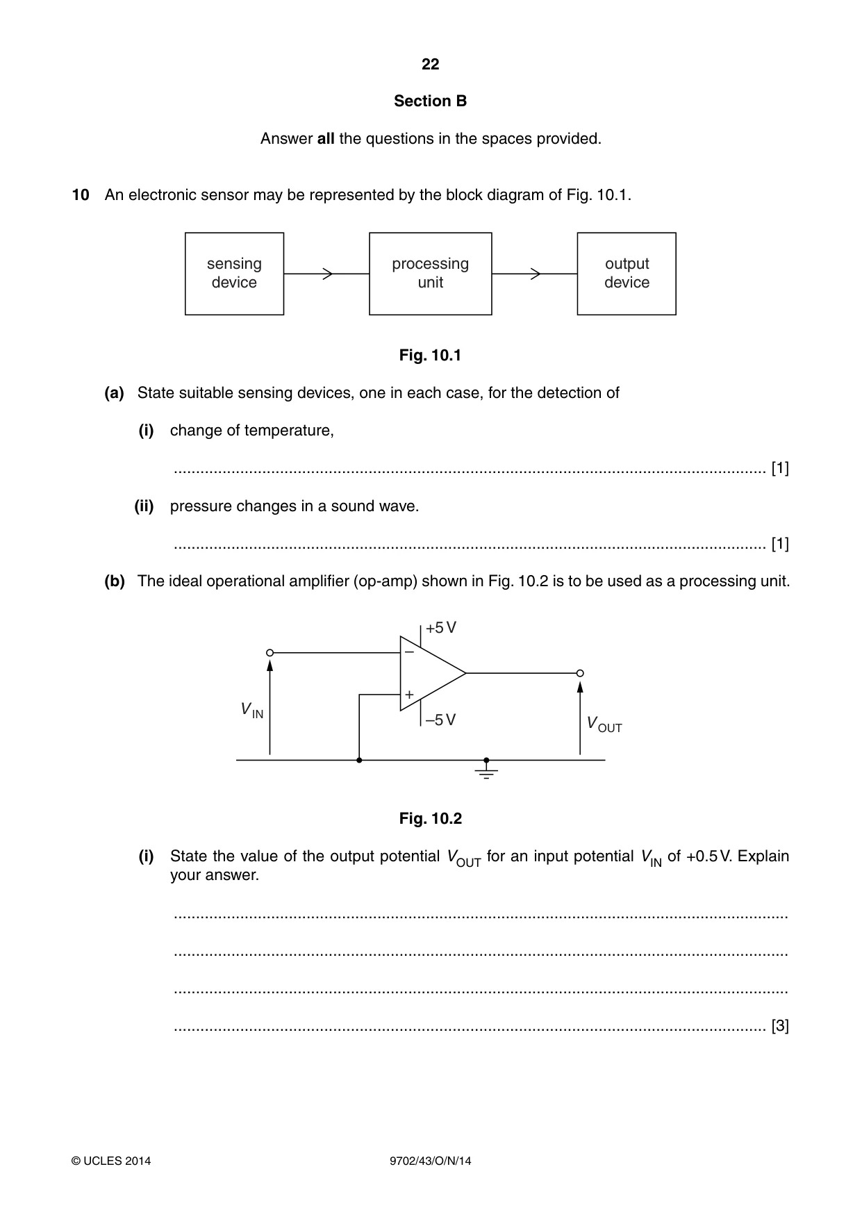
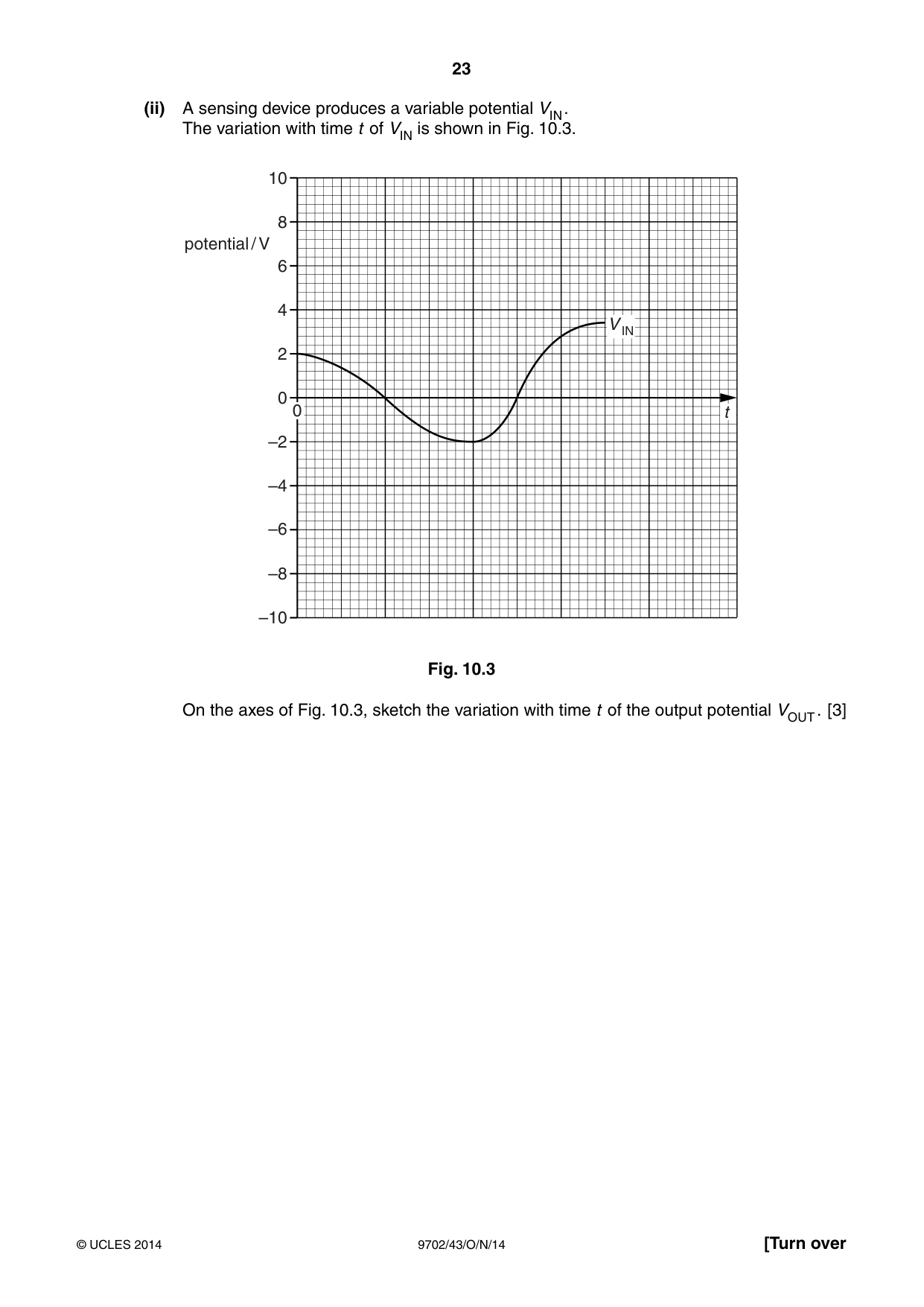
10 An electronic sensor may be represented by the block diagram of Fig. 10.1. sensing processing output device unit device Fig. 10.1 (a) State suitable sensing devices, one in each case, for the detection of (i) change of temperature, ...................................................................................................................................... [1] (ii) pressure changes in a sound wave. ...................................................................................................................................... [1] (b) The ideal operational amplifier (op-amp) shown in Fig. 10.2 is to be used as a processing unit. +5 V – + V IN –5 V V OUT Fig. 10.2 (i) State the value of the output potential VOUT for an input potential VIN of +0.5 V. Explain your answer. ........................................................................................................................................... ........................................................................................................................................... ........................................................................................................................................... ...................................................................................................................................... [3] (ii) A sensing device produces a variable potential VIN . The variation with time t of VIN is shown in Fig. 10.3. 10 8 potential / V 6 4 V IN 2 0 0 t –2 –4 –6 –8 –10 Fig. 10.3 On the axes of Fig. 10.3, sketch the variation with time t of the output potential VOUT . [3]
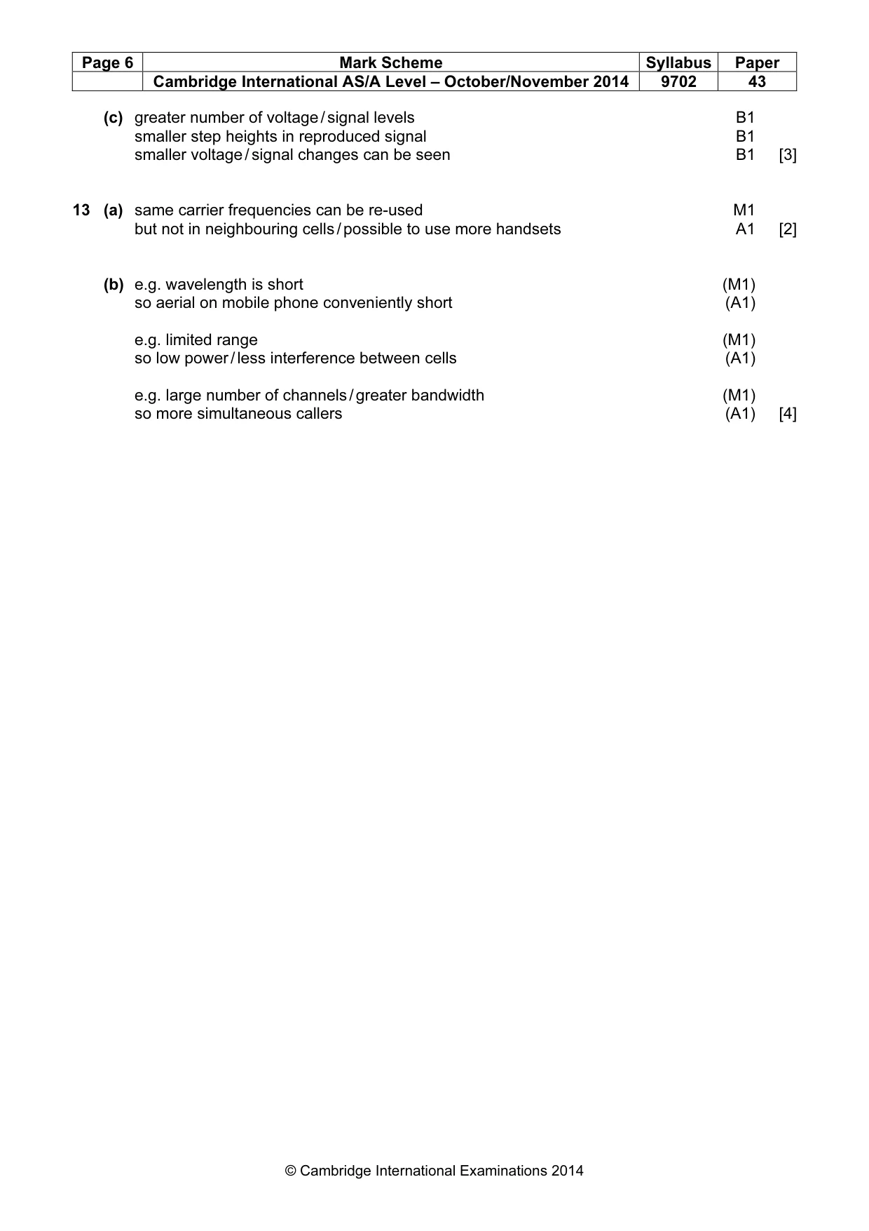
Mark scheme: 10 (a) (i) thermistor / thermocouple B1 [1] (ii) quartz crystal / piezoelectric crystal or transducer / microphone B1 [1] (b) (i) VOUT = –5 V A1 inverting input is positive or V– is positive or V– > V+ so VOUT is negative B1 op-amp has very large / infinite gain and so saturates B1 [3] (ii) sketch: VOUT switches from (+) to (–) when VIN is zero B1 VOUT is +5 V or –5 V M1 VOUT is negative when VIN is positive (or v.v.) A1 [3]
Q11 · By reference to ultrasound waves, state what is meant by the specific acoustic impedance…
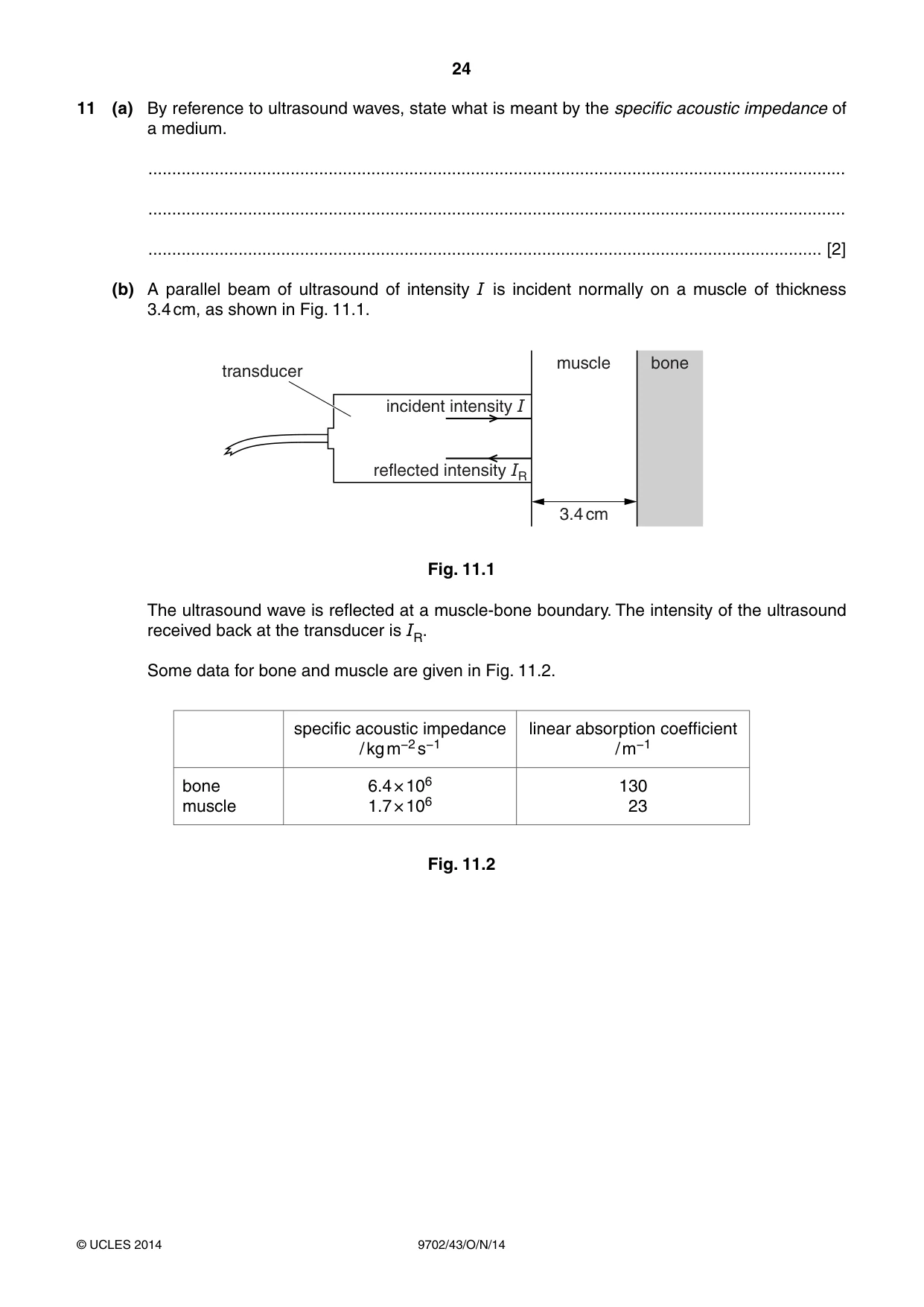
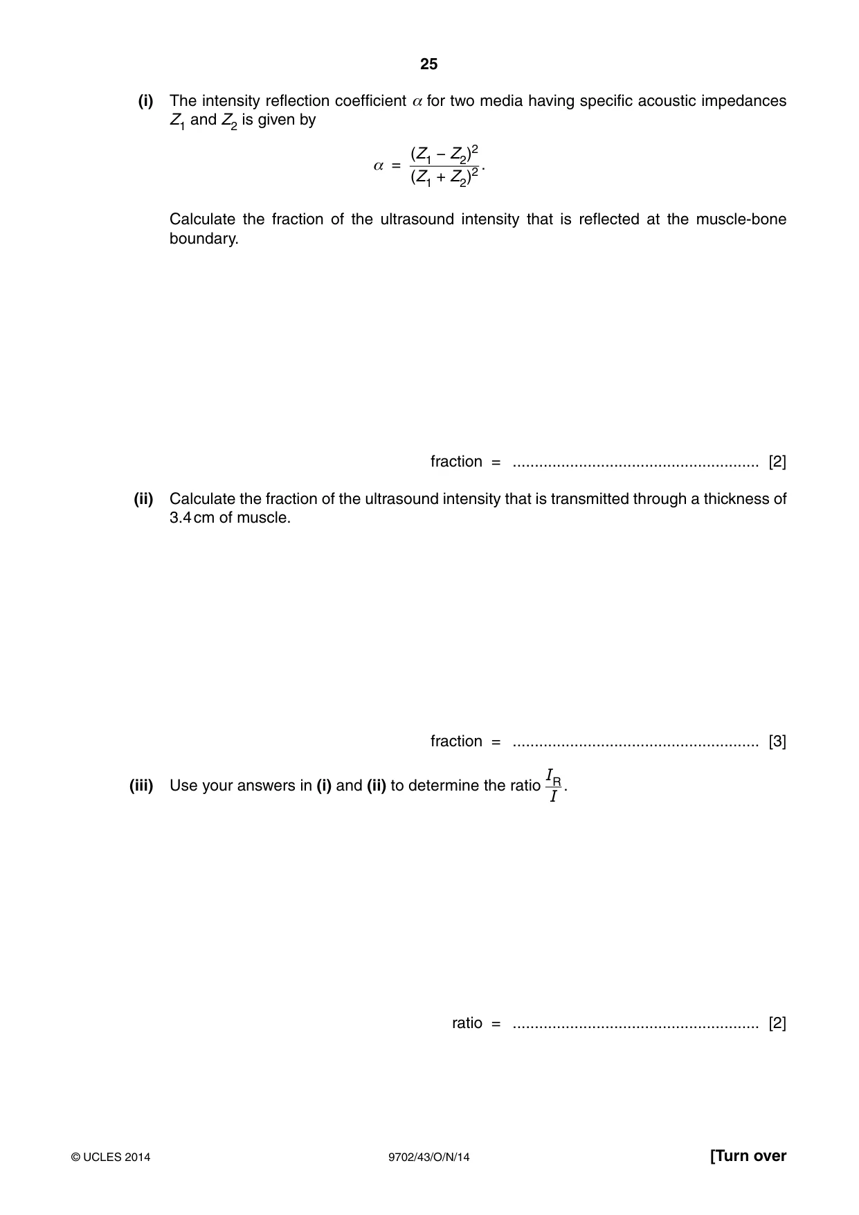
11 (a) By reference to ultrasound waves, state what is meant by the specific acoustic impedance of a medium. ................................................................................................................................................... ................................................................................................................................................... .............................................................................................................................................. [2] (b) A parallel beam of ultrasound of intensity I is incident normally on a muscle of thickness 3.4 cm, as shown in Fig. 11.1. muscle bone transducer incident intensity I reflected intensity IR 3.4 cm Fig. 11.1 The ultrasound wave is reflected at a muscle-bone boundary. The intensity of the ultrasound received back at the transducer is IR. Some data for bone and muscle are given in Fig. 11.2. specific acoustic impedance linear absorption coefficient / kg m−2 s−1 / m−1 bone 6.4 × 10⁶ 130 muscle 1.7 × 10⁶ 23 Fig. 11.2 (i) The intensity reflection coefficient α for two media having specific acoustic impedances Z1 and Z2 is given by (Z1 − Z2)2 α = . (Z1 + Z2)2 Calculate the fraction of the ultrasound intensity that is reflected at the muscle-bone boundary. fraction = ........................................................ [2] (ii) Calculate the fraction of the ultrasound intensity that is transmitted through a thickness of 3.4 cm of muscle. fraction = ........................................................ [3] IR(iii) Use your answers in (i) and (ii) to determine the ratio . I ratio = ........................................................ [2]
Mark scheme: 11 (a) product of density and speed M1 density of medium, speed of wave in medium A1 [2] (not “speed of light”, 0 / 2) (b) (i) α = (6.4 – 1.7)2 / (6.4 + 1.7)2 C1 = 0.34 A1 [2] (ii) I / I0 = e–µx C1 = exp (–23 × 3.4 × 10–2) C1 = 0.46 A1 [3] (iii) IR / I = (0.46)2 × 0.34 C1 = 0.072 A1 [2]
Q12 · Distinguish between an analogue signal and a digital signal
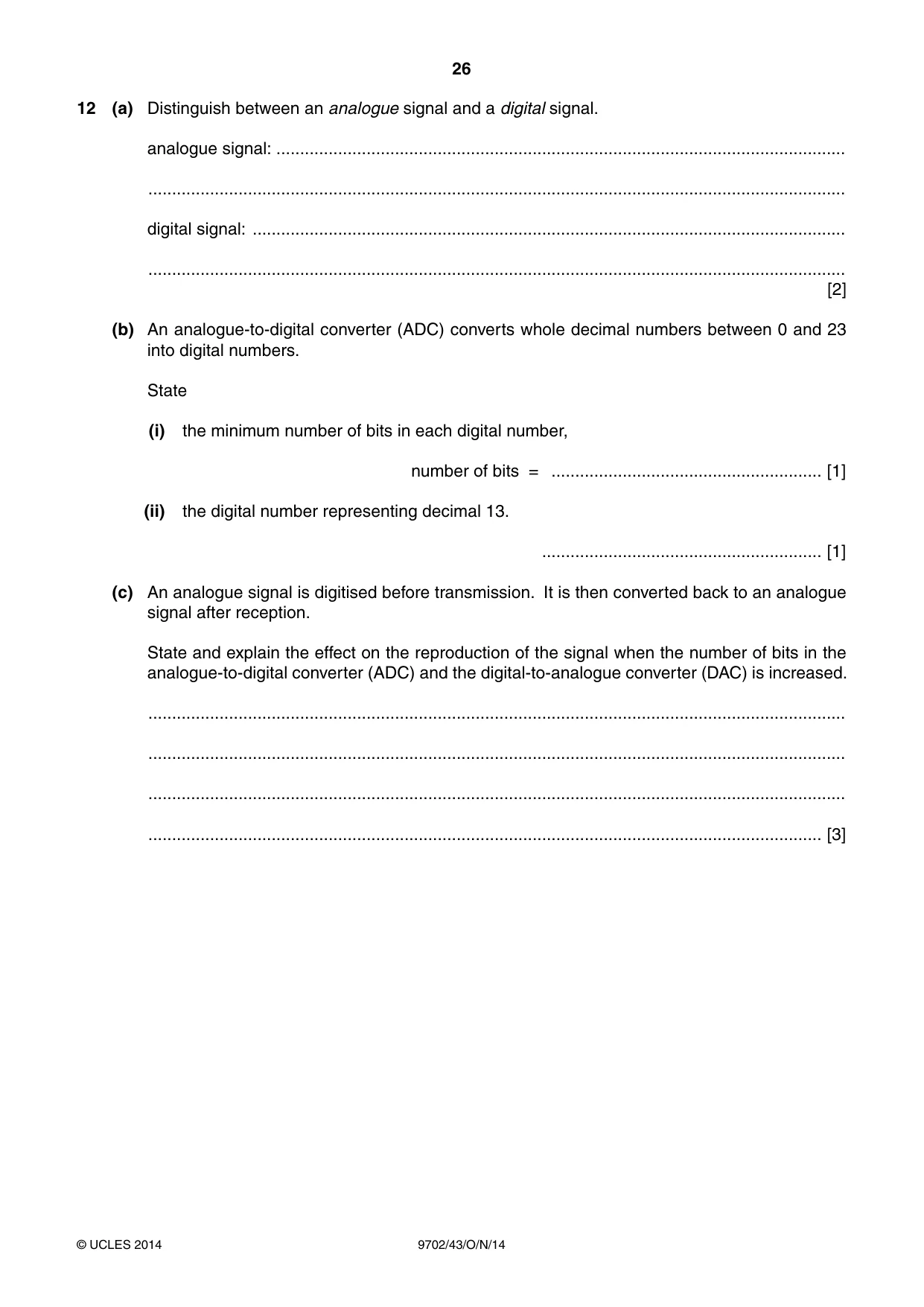
12 (a) Distinguish between an analogue signal and a digital signal. analogue signal: ........................................................................................................................ ................................................................................................................................................... digital signal: ............................................................................................................................. ................................................................................................................................................... [2] (b) An analogue-to-digital converter (ADC) converts whole decimal numbers between 0 and 23 into digital numbers. State (i) the minimum number of bits in each digital number, number of bits = ......................................................... [1] (ii) the digital number representing decimal 13. ........................................................... [1] (c) An analogue signal is digitised before transmission. It is then converted back to an analogue signal after reception. State and explain the effect on the reproduction of the signal when the number of bits in the analogue-to-digital converter (ADC) and the digital-to-analogue converter (DAC) is increased. ................................................................................................................................................... ................................................................................................................................................... ................................................................................................................................................... .............................................................................................................................................. [3]
Mark scheme: 12 (a) analogue: continuously variable B1 digital: two / distinct levels only or 1 s and 0 s or highs and lows B1 [2] (b) (i) 5 A1 [1] (ii) 1 1 0 1 A1 [1] (c) greater number of voltage / signal levels B1 smaller step heights in reproduced signal B1 smaller voltage / signal changes can be seen B1 [3]
Q13 · In a mobile phone system, the country is divided into a number of cells, each with its…
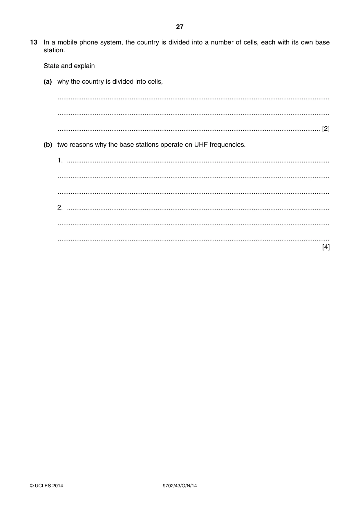
13 In a mobile phone system, the country is divided into a number of cells, each with its own base station. State and explain (a) why the country is divided into cells, ................................................................................................................................................... ................................................................................................................................................... .............................................................................................................................................. [2] (b) two reasons why the base stations operate on UHF frequencies. 1. .............................................................................................................................................. ................................................................................................................................................... ................................................................................................................................................... 2. .............................................................................................................................................. ................................................................................................................................................... ................................................................................................................................................... [4]
Mark scheme: 13 (a) same carrier frequencies can be re-used M1 but not in neighbouring cells / possible to use more handsets A1 [2] (b) e.g. wavelength is short (M1) so aerial on mobile phone conveniently short (A1) e.g. limited range (M1) so low power / less interference between cells (A1) e.g. large number of channels / greater bandwidth (M1) so more simultaneous callers (A1) [4]
What was in this paper
The subtopics covered by these 13 questions, and how many questions each got. Open one in a new tab to see every Cambridge question on it.
3Electromagnetic spectrum1Energy and momentum of a photon1Energy in simple harmonic motion1Force on a moving charge1Potential difference and power1Practical circuits1Production and use of ultrasound1Radioactive decay1Simple harmonic oscillations1The first law of thermodynamics1What you needed in this session
Cambridge’s own grade thresholds for 2014 Oct/Nov, Paper 4 · Variant 3. A higher threshold means an easier paper — the bar moves with how the cohort did.