Cambridge A Level Physics 9702 — 2010 May/June Paper 4 · Variant 3
9702/43/M/J/10 · 12 questions · 100 marks · ≈113 min
The question paper and its mark scheme, free to read here and free to download. This is Cambridge’s own paper, exactly as it was sat.
Question paper20 pages
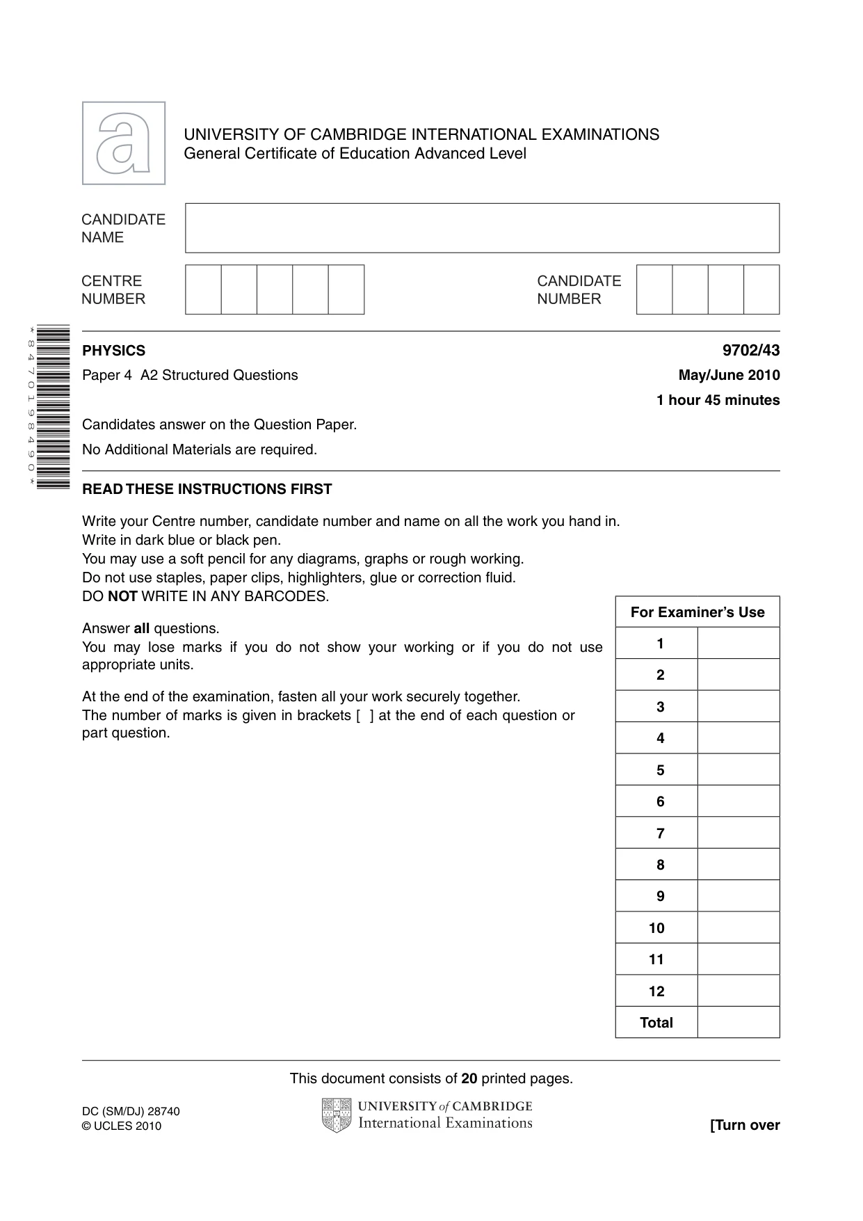

Mark scheme6 pages
Answers below. Sit the paper first if you are practising.
Questions as text
Q1 · Define gravitational potential at a point
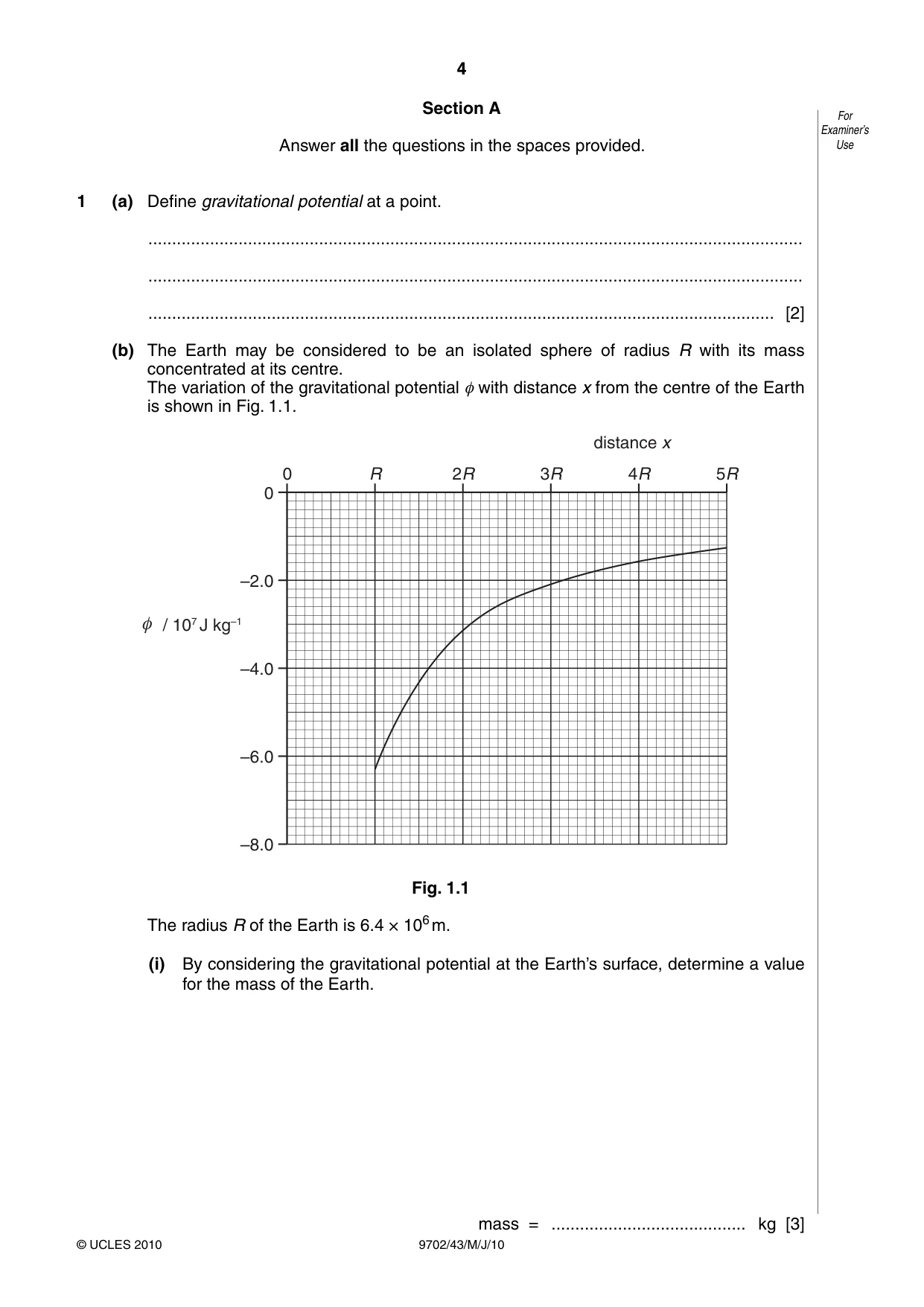
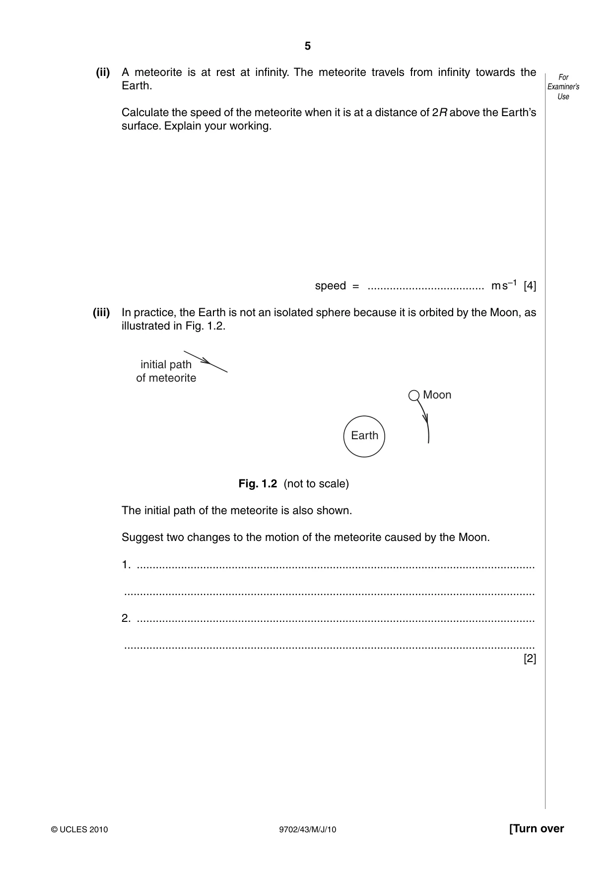
1 (a) Define gravitational potential at a point. .......................................................................................................................................... .......................................................................................................................................... .................................................................................................................................... [2] (b) The Earth may be considered to be an isolated sphere of radius R with its mass concentrated at its centre. The variation of the gravitational potential φ with distance x from the centre of the Earth is shown in Fig. 1.1. distance x 0 R 2R 3R 4R 5R 0 –2.0 / 107 J kg–1 –4.0 –6.0 –8.0 Fig. 1.1 The radius R of the Earth is 6.4 × 10⁶ m. (i) By considering the gravitational potential at the Earth’s surface, determine a value for the mass of the Earth. mass = ......................................... kg [3] (ii) A meteorite is at rest at infinity. The meteorite travels from infinity towards the For Earth. Examiner’s Use Calculate the speed of the meteorite when it is at a distance of 2R above the Earth’s surface. Explain your working. speed = ..................................... m s–1 [4] (iii) In practice, the Earth is not an isolated sphere because it is orbited by the Moon, as illustrated in Fig. 1.2. initial path of meteorite Moon Earth Fig. 1.2 (not to scale) The initial path of the meteorite is also shown. Suggest two changes to the motion of the meteorite caused by the Moon. 1. .............................................................................................................................. .................................................................................................................................. 2. .............................................................................................................................. .................................................................................................................................. [2]
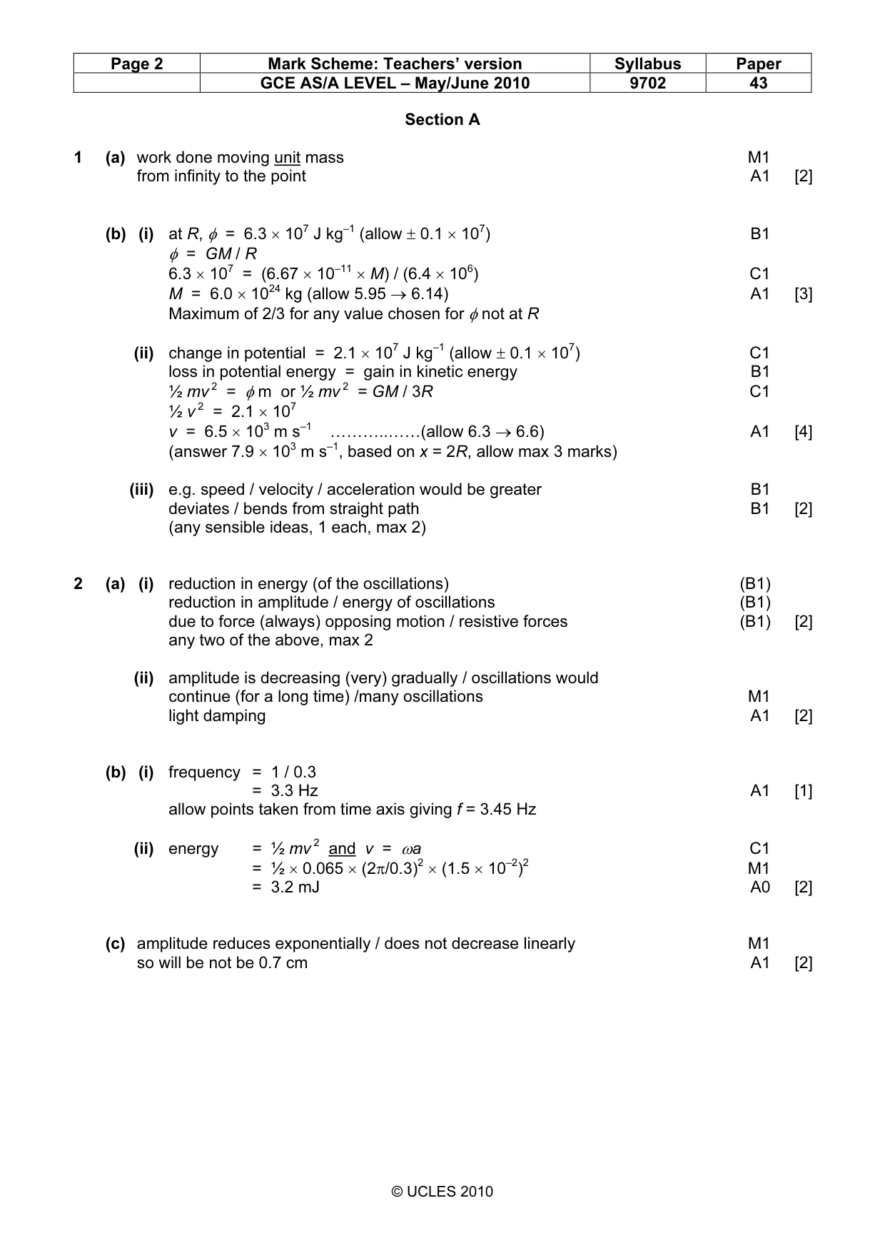
Mark scheme: 1 (a) work done moving unit mass M1 from infinity to the point A1 [2] (b) (i) at R, φ = 6.3 × 10⁷ J kg–1 (allow ± 0.1 × 10⁷) B1 φ = GM / R 6.3 × 107 = (6.67 × 10⁻¹¹ × M) / (6.4 × 10⁶) C1 M = 6.0 × 1024 kg (allow 5.95 → 6.14) A1 [3] Maximum of 2/3 for any value chosen for φ not at R (ii) change in potential = 2.1 × 10⁷ J kg–1 (allow ± 0.1 × 10⁷) C1 loss in potential energy = gain in kinetic energy B1 ½ mv 2 = φ m or ½ mv 2 = GM / 3R C1 ½ v 2 = 2.1 × 10⁷ v = 6.5 × 10³ m s–1 ………..……(allow 6.3 → 6.6) A1 [4] (answer 7.9 × 10³ m s–1, based on x = 2R, allow max 3 marks) (iii) e.g. speed / velocity / acceleration would be greater B1 deviates / bends from straight path B1 [2] (any sensible ideas, 1 each, max 2)
Q2 · A long strip of springy steel is clamped at one end so that the strip is vertical
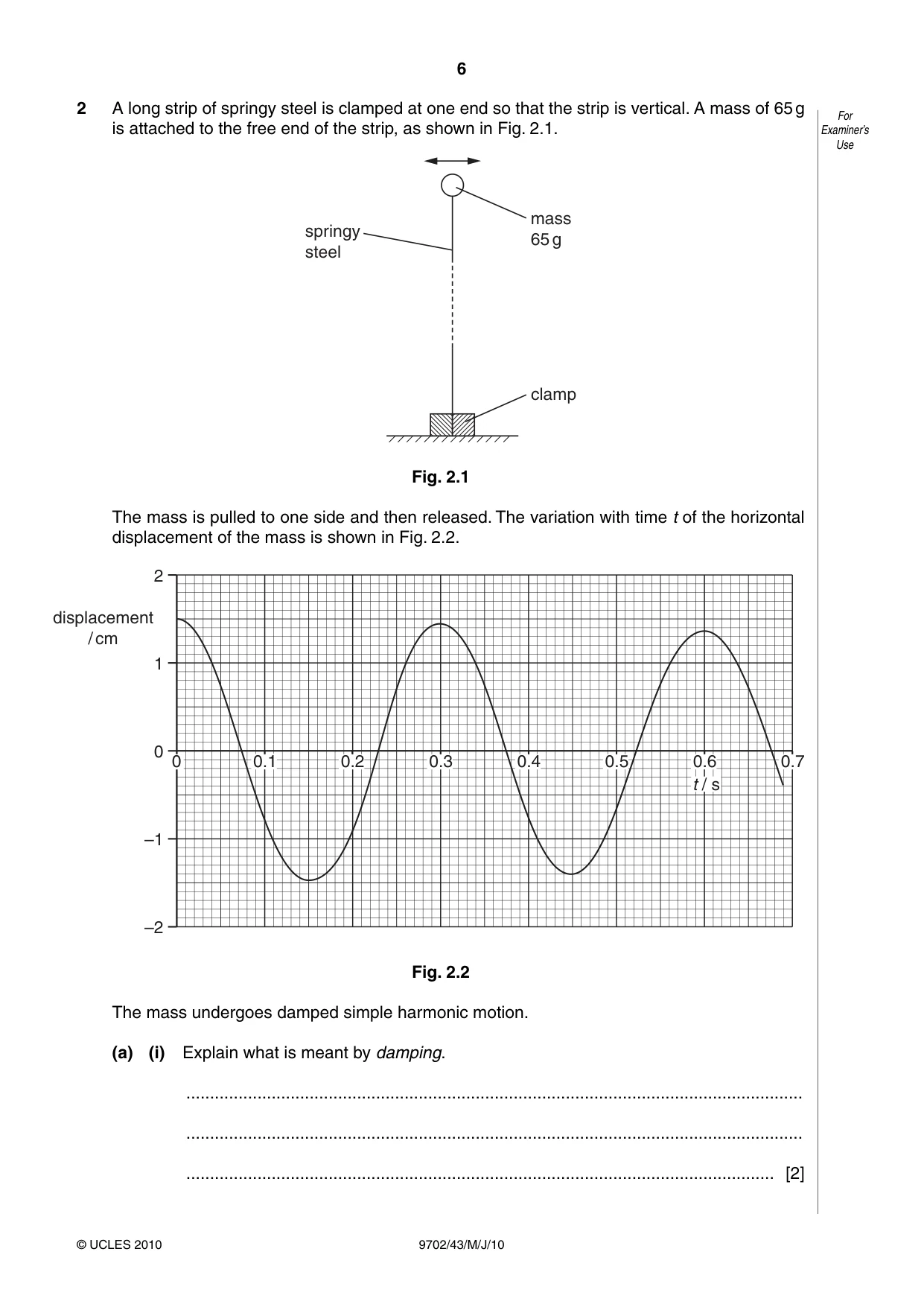
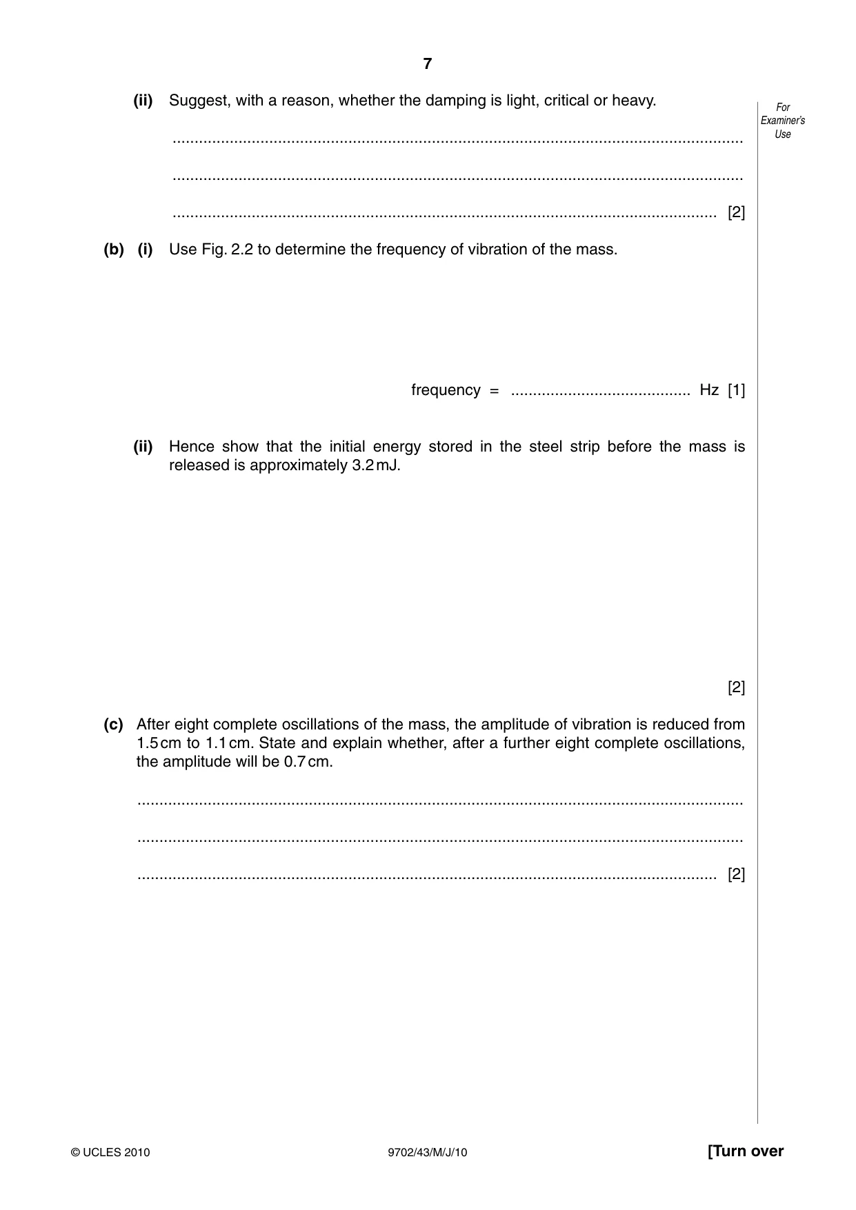
2 A long strip of springy steel is clamped at one end so that the strip is vertical. A mass of 65 g For is attached to the free end of the strip, as shown in Fig. 2.1. Examiner’s Use mass springy 65 g steel clamp Fig. 2.1 The mass is pulled to one side and then released. The variation with time t of the horizontal displacement of the mass is shown in Fig. 2.2. 2 displacement / cm 1 0 0 0.10.10.1 0.2 0.3 0.4 0.5 0.6 0.7 t / s –1 –2 Fig. 2.2 The mass undergoes damped simple harmonic motion. (a) (i) Explain what is meant by damping. .................................................................................................................................. .................................................................................................................................. ............................................................................................................................ [2] (ii) Suggest, with a reason, whether the damping is light, critical or heavy. For Examiner’s .................................................................................................................................. Use .................................................................................................................................. ............................................................................................................................ [2] (b) (i) Use Fig. 2.2 to determine the frequency of vibration of the mass. frequency = ......................................... Hz [1] (ii) Hence show that the initial energy stored in the steel strip before the mass is released is approximately 3.2 mJ. [2] (c) After eight complete oscillations of the mass, the amplitude of vibration is reduced from 1.5 cm to 1.1 cm. State and explain whether, after a further eight complete oscillations, the amplitude will be 0.7 cm. .......................................................................................................................................... .......................................................................................................................................... .................................................................................................................................... [2]
Mark scheme: 2 (a) (i) reduction in energy (of the oscillations) (B1) reduction in amplitude / energy of oscillations (B1) due to force (always) opposing motion / resistive forces (B1) [2] any two of the above, max 2 (ii) amplitude is decreasing (very) gradually / oscillations would continue (for a long time) /many oscillations M1 light damping A1 [2] (b) (i) frequency = 1 / 0.3 = 3.3 Hz A1 [1] allow points taken from time axis giving f = 3.45 Hz (ii) energy = ½ mv 2 and v = ωa C1 = ½ × 0.065 × (2π/0.3)2 × (1.5 × 10–2)2 M1 = 3.2 mJ A0 [2] (c) amplitude reduces exponentially / does not decrease linearly M1 so will be not be 0.7 cm A1 [2] GCE AS/A LEVEL – May/June 2010 9702 43
Q3 · The resistance of a thermistor at 0 °C is 3840 Ω
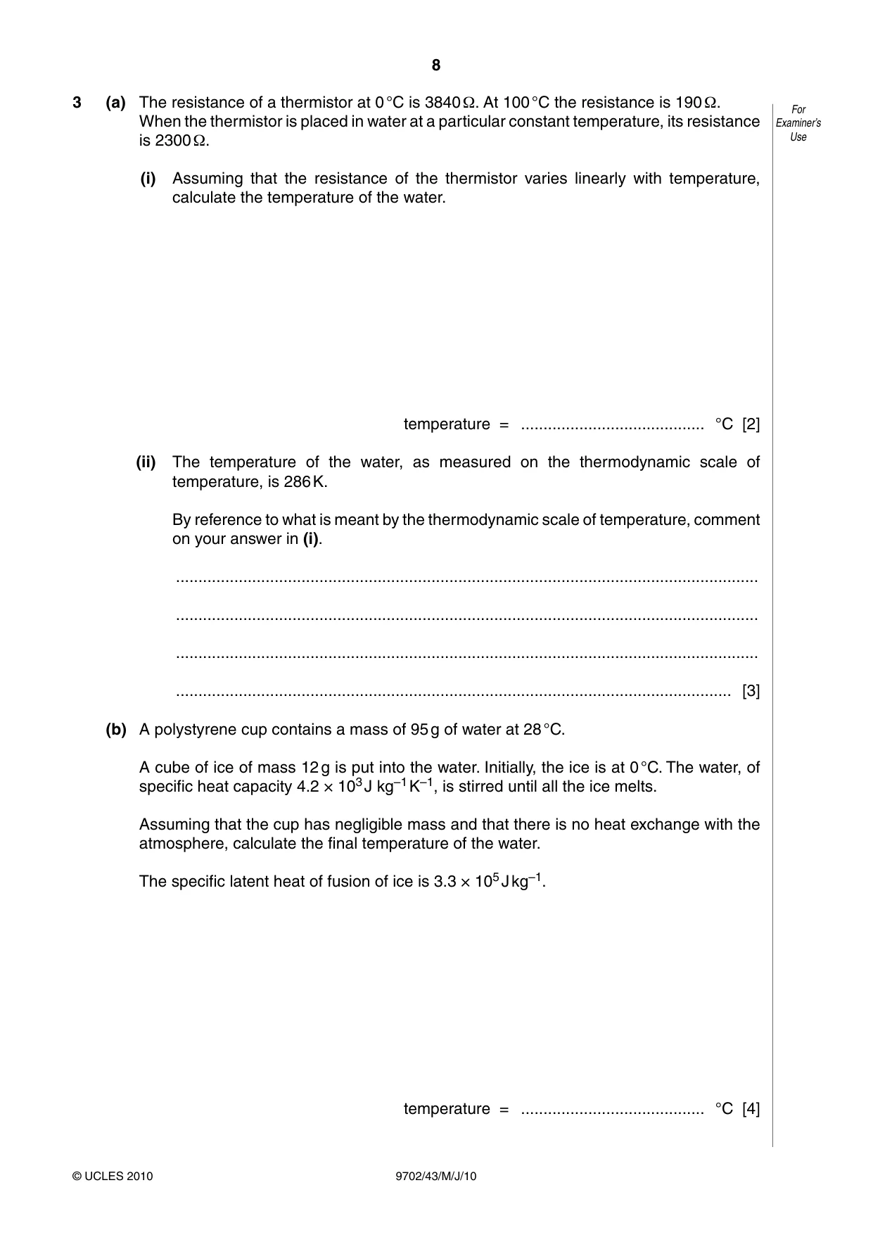
3 (a) The resistance of a thermistor at 0 °C is 3840 Ω. At 100 °C the resistance is 190 Ω. For When the thermistor is placed in water at a particular constant temperature, its resistance Examiner’s is 2300 Ω. Use (i) Assuming that the resistance of the thermistor varies linearly with temperature, calculate the temperature of the water. temperature = ......................................... °C [2] (ii) The temperature of the water, as measured on the thermodynamic scale of temperature, is 286 K. By reference to what is meant by the thermodynamic scale of temperature, comment on your answer in (i). .................................................................................................................................. .................................................................................................................................. .................................................................................................................................. ............................................................................................................................ [3] (b) A polystyrene cup contains a mass of 95 g of water at 28 °C. A cube of ice of mass 12 g is put into the water. Initially, the ice is at 0 °C. The water, of specific heat capacity 4.2 × 10³ J kg–1 K–1, is stirred until all the ice melts. Assuming that the cup has negligible mass and that there is no heat exchange with the atmosphere, calculate the final temperature of the water. The specific latent heat of fusion of ice is 3.3 × 10⁵ J kg–1. temperature = ......................................... °C [4]
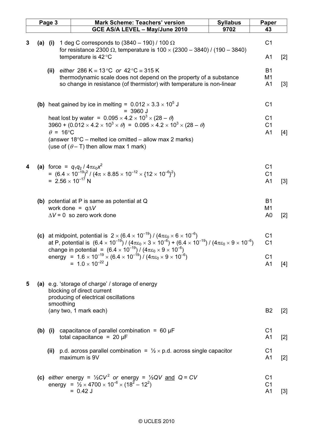
Mark scheme: 3 (a) (i) 1 deg C corresponds to (3840 – 190) / 100 Ω C1 for resistance 2300 Ω, temperature is 100 × (2300 – 3840) / (190 – 3840) temperature is 42 °C A1 [2] (ii) either 286 K ≡ 13 °C or 42 °C ≡ 315 K B1 thermodynamic scale does not depend on the property of a substance M1 so change in resistance (of thermistor) with temperature is non-linear A1 [3] (b) heat gained by ice in melting = 0.012 × 3.3 × 105 J C1 = 3960 J heat lost by water = 0.095 × 4.2 × 103 × (28 – θ) C1 3960 + (0.012 × 4.2 × 103 × θ) = 0.095 × 4.2 × 103 × (28 – θ) C1 θ = 16°C A1 [4] (answer 18°C – melted ice omitted – allow max 2 marks) (use of (θ – T) then allow max 1 mark) 2
Q4 · Two point charges A and B each have a charge of + 6.4 × 10⁻¹⁹ C
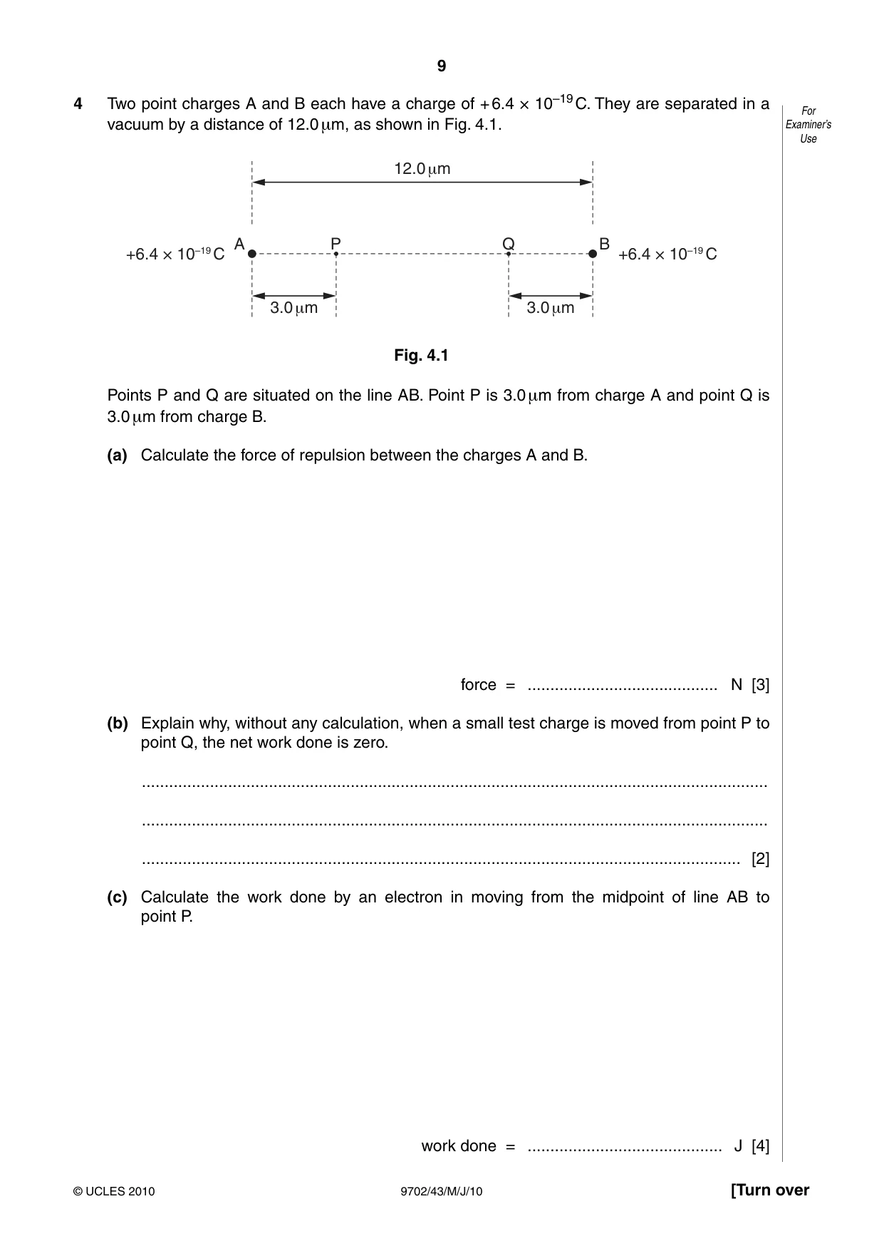
4 Two point charges A and B each have a charge of + 6.4 × 10⁻¹⁹ C. They are separated in a For vacuum by a distance of 12.0 μm, as shown in Fig. 4.1. Examiner’s Use 12.0 μm A P Q B +6.4 × 10⁻¹⁹ C +6.4 × 10⁻¹⁹ C 3.0 μm 3.0 μm Fig. 4.1 Points P and Q are situated on the line AB. Point P is 3.0 μm from charge A and point Q is 3.0 μm from charge B. (a) Calculate the force of repulsion between the charges A and B. force = .......................................... N [3] (b) Explain why, without any calculation, when a small test charge is moved from point P to point Q, the net work done is zero. .......................................................................................................................................... .......................................................................................................................................... .................................................................................................................................... [2] (c) Calculate the work done by an electron in moving from the midpoint of line AB to point P. work done = ........................................... J [4]
Mark scheme: 4 (a) force = q1q2 / 4πε0x2 C1 = (6.4 × 10⁻¹⁹)2 / (4π × 8.85 × 10–12 × {12 × 10–6}2) C1 = 2.56 × 10⁻¹⁷ N A1 [3] (b) potential at P is same as potential at Q B1 work done = q∆V M1 ∆V = 0 so zero work done A0 [2] (c) at midpoint, potential is 2 × (6.4 × 10–19) / (4πε0 × 6 × 10–6) C1 at P, potential is (6.4 × 10⁻¹⁹) / (4πε0 × 3 × 10–6) + (6.4 × 10⁻¹⁹) / (4πε0 × 9 × 10–6) C1 change in potential = (6.4 × 10⁻¹⁹) / (4πε0 × 9 × 10–6) energy = 1.6 × 10–19 × (6.4 × 10–19) / (4πε0 × 9 × 10–6) C1 = 1.0 × 10⁻²² J A1 [4]
Q5 · State two functions of capacitors in electrical circuits
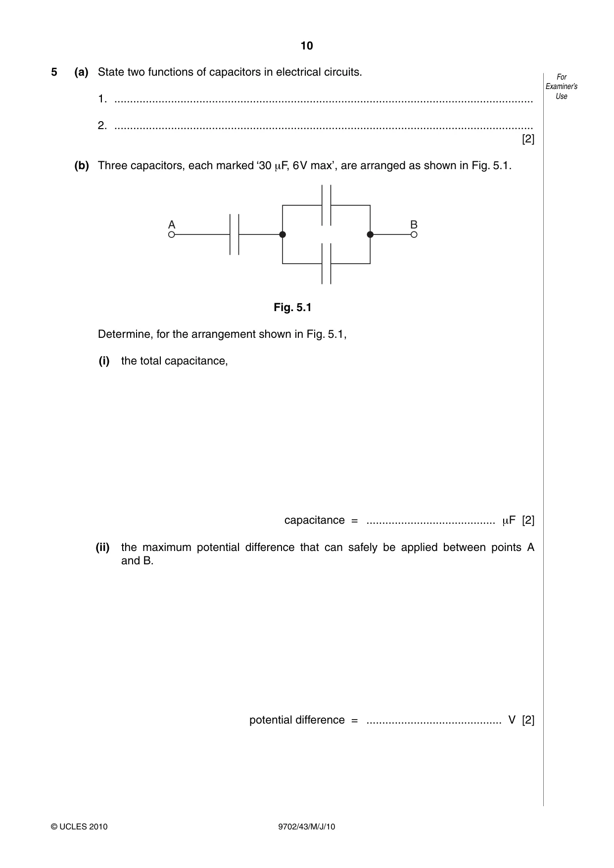
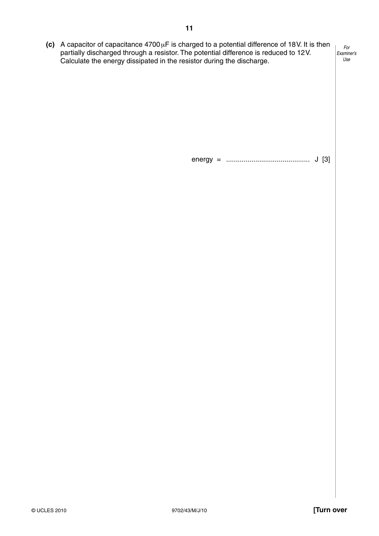
5 (a) State two functions of capacitors in electrical circuits. For Examiner’s 1. ..................................................................................................................................... Use 2. ..................................................................................................................................... [2] (b) Three capacitors, each marked ‘30 μF, 6 V max’, are arranged as shown in Fig. 5.1. A B Fig. 5.1 Determine, for the arrangement shown in Fig. 5.1, (i) the total capacitance, capacitance = ......................................... μF [2] (ii) the maximum potential difference that can safely be applied between points A and B. potential difference = ........................................... V [2] (c) A capacitor of capacitance 4700 μF is charged to a potential difference of 18 V. It is then For partially discharged through a resistor. The potential difference is reduced to 12 V. Examiner’s Calculate the energy dissipated in the resistor during the discharge. Use energy = ........................................... J [3]
Mark scheme: 5 (a) e.g. ‘storage of charge’ / storage of energy blocking of direct current producing of electrical oscillations smoothing (any two, 1 mark each) B2 [2] (b) (i) capacitance of parallel combination = 60 µF C1 total capacitance = 20 µF A1 [2] (ii) p.d. across parallel combination = ½ × p.d. across single capacitor C1 maximum is 9V A1 [2] (c) either energy = ½CV 2 or energy = ½QV and Q = CV C1 energy = ½ × 4700 × 10–6 × (182 – 122) C1 = 0.42 J A1 [3] GCE AS/A LEVEL – May/June 2010 9702 43
Q6 · A uniform magnetic field has constant flux density B
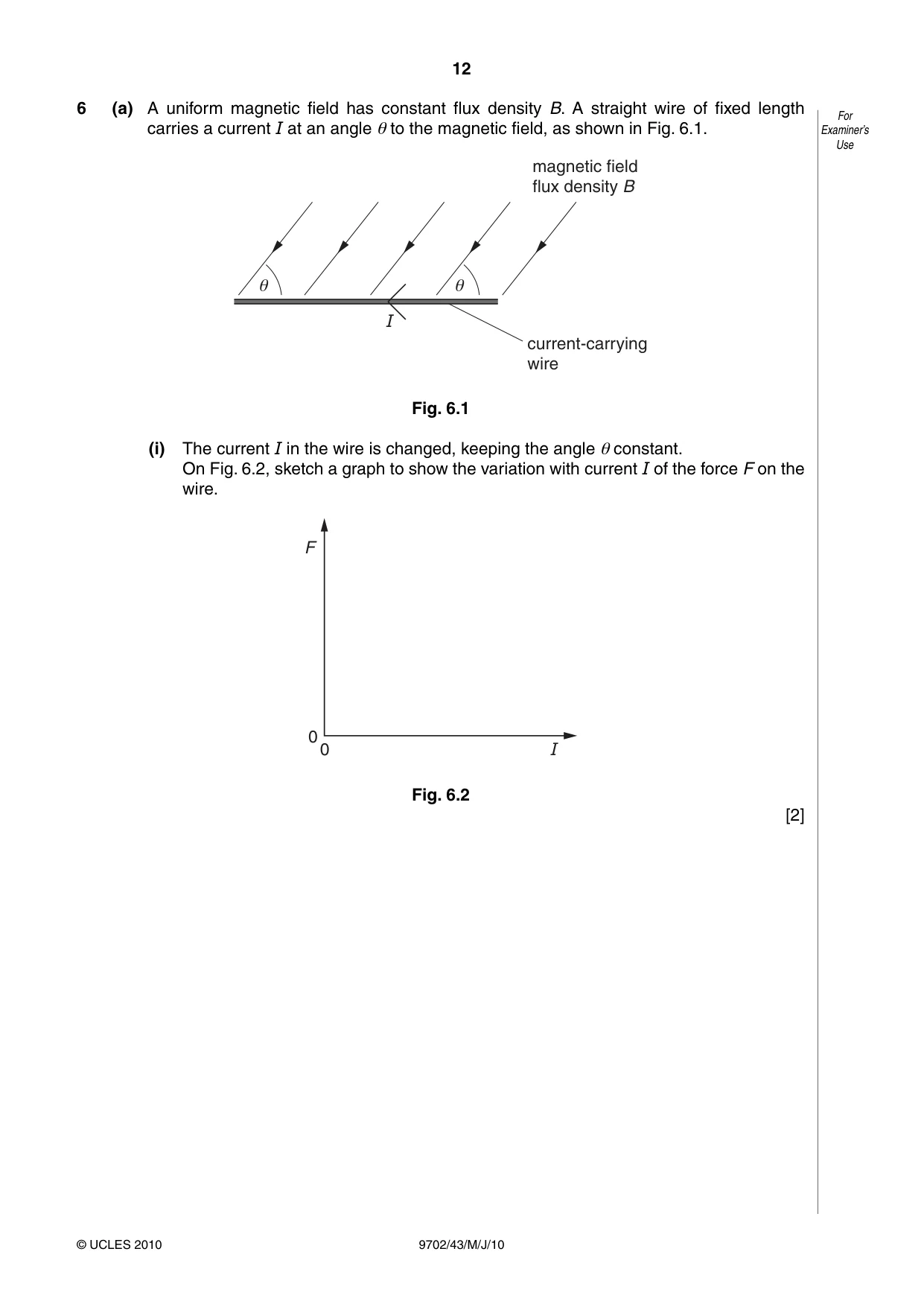
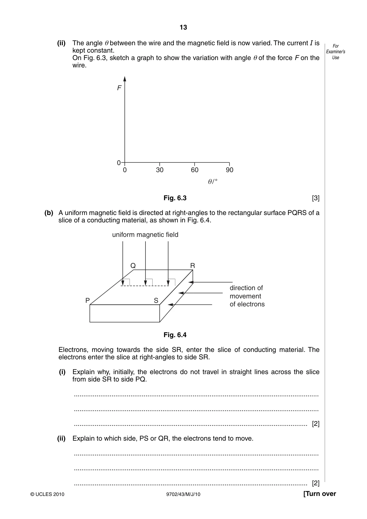
6 (a) A uniform magnetic field has constant flux density B. A straight wire of fixed length For carries a current I at an angle θ to the magnetic field, as shown in Fig. 6.1. Examiner’s Use magnetic field flux density B I current-carrying wire Fig. 6.1 (i) The current I in the wire is changed, keeping the angle θ constant. On Fig. 6.2, sketch a graph to show the variation with current I of the force F on the wire. F 0 0 I Fig. 6.2 [2] (ii) The angle θ between the wire and the magnetic field is now varied. The current I is For kept constant. Examiner’s On Fig. 6.3, sketch a graph to show the variation with angle θ of the force F on the Use wire. F 0 0 30 60 90 / ° Fig. 6.3 [3] (b) A uniform magnetic field is directed at right-angles to the rectangular surface PQRS of a slice of a conducting material, as shown in Fig. 6.4. uniform magnetic field Q R direction of movement P S of electrons Fig. 6.4 Electrons, moving towards the side SR, enter the slice of conducting material. The electrons enter the slice at right-angles to side SR. (i) Explain why, initially, the electrons do not travel in straight lines across the slice from side SR to side PQ. .................................................................................................................................. .................................................................................................................................. ............................................................................................................................ [2] (ii) Explain to which side, PS or QR, the electrons tend to move. .................................................................................................................................. .................................................................................................................................. ............................................................................................................................ [2]
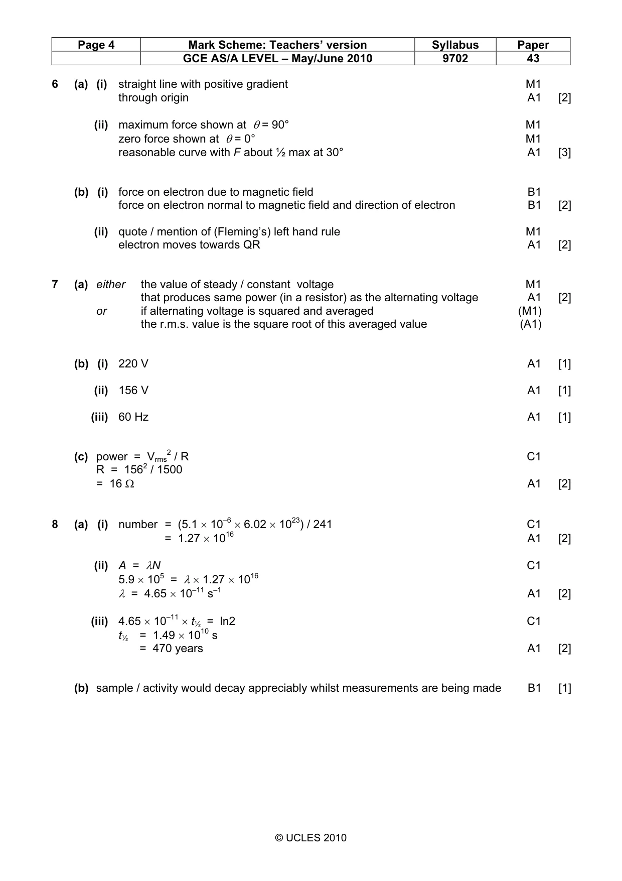
Mark scheme: 6 (a) (i) straight line with positive gradient M1 through origin A1 [2] (ii) maximum force shown at θ = 90° M1 zero force shown at θ = 0° M1 reasonable curve with F about ½ max at 30° A1 [3] (b) (i) force on electron due to magnetic field B1 force on electron normal to magnetic field and direction of electron B1 [2] (ii) quote / mention of (Fleming’s) left hand rule M1 electron moves towards QR A1 [2]
Q7 · Explain what is meant by the root-mean-square (r.m.s.) value of an alternating voltage
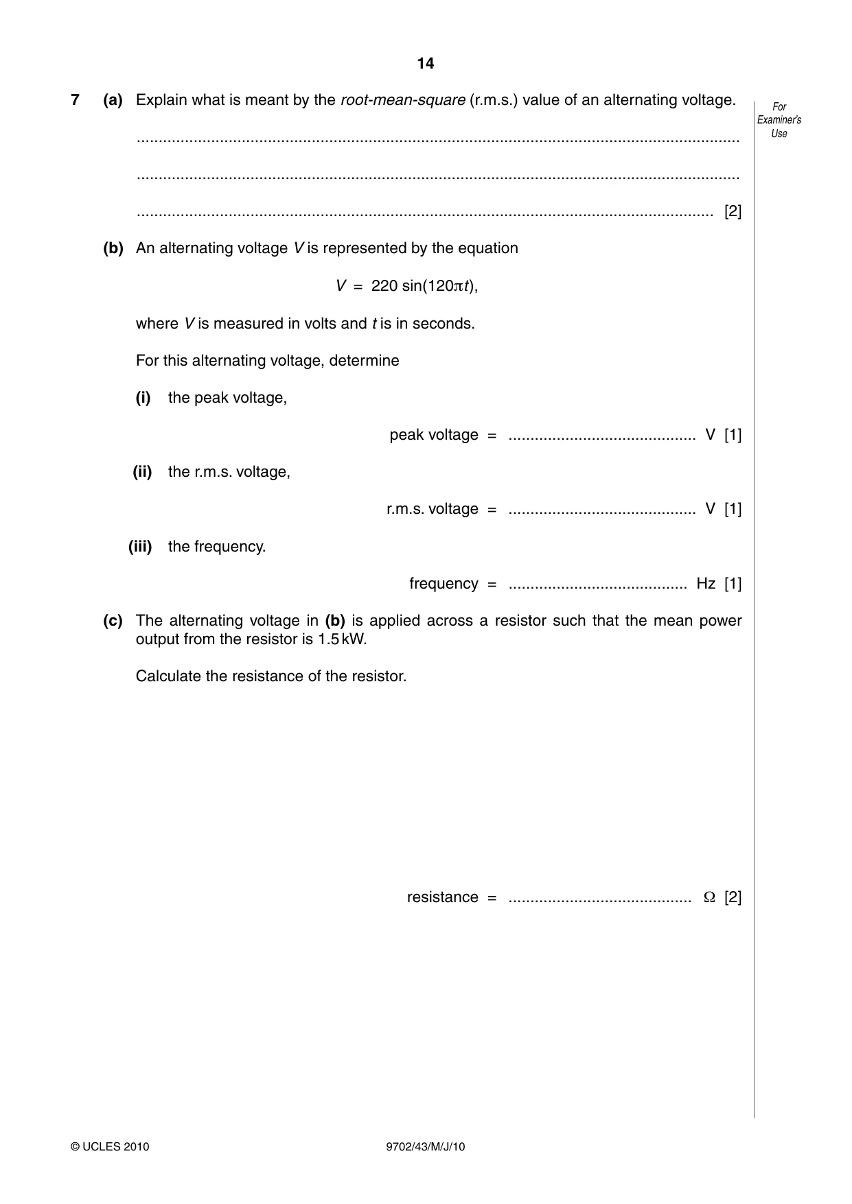
7 (a) Explain what is meant by the root-mean-square (r.m.s.) value of an alternating voltage. For Examiner’s .......................................................................................................................................... Use .......................................................................................................................................... .................................................................................................................................... [2] (b) An alternating voltage V is represented by the equation V = 220 sin(120πt), where V is measured in volts and t is in seconds. For this alternating voltage, determine (i) the peak voltage, peak voltage = ........................................... V [1] (ii) the r.m.s. voltage, r.m.s. voltage = ........................................... V [1] (iii) the frequency. frequency = ......................................... Hz [1] (c) The alternating voltage in (b) is applied across a resistor such that the mean power output from the resistor is 1.5 kW. Calculate the resistance of the resistor. resistance = .......................................... Ω [2]
Mark scheme: 7 (a) either the value of steady / constant voltage M1 that produces same power (in a resistor) as the alternating voltage A1 [2] or if alternating voltage is squared and averaged (M1) the r.m.s. value is the square root of this averaged value (A1) (b) (i) 220 V A1 [1] (ii) 156 V A1 [1] (iii) 60 Hz A1 [1] (c) power = Vrms2 / R C1 R = 1562 / 1500 = 16 Ω A1 [2] 6 23
Q8 · Americium-241 is an artificially produced radioactive element that emits α-particles
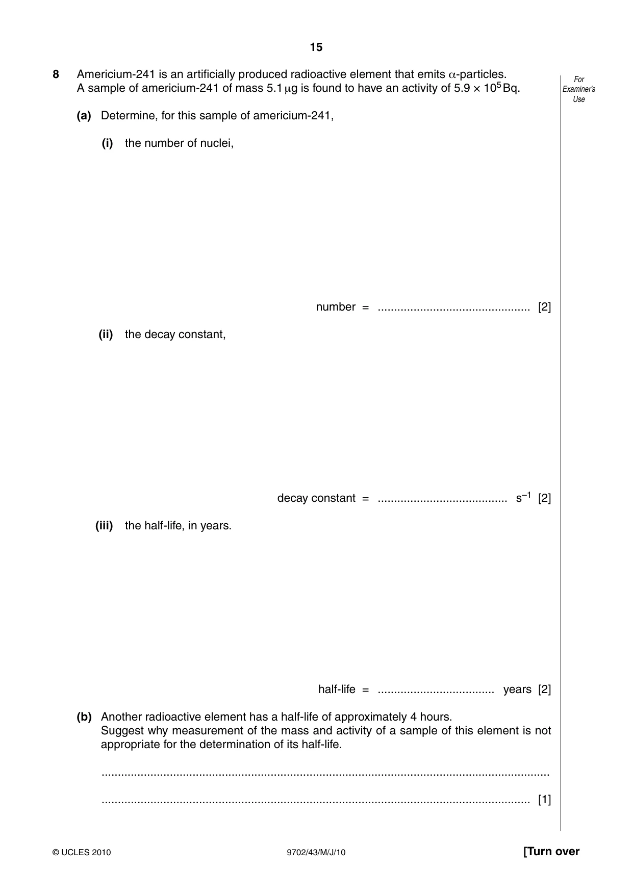
8 Americium-241 is an artificially produced radioactive element that emits α-particles. For A sample of americium-241 of mass 5.1 μg is found to have an activity of 5.9 × 10⁵ Bq. Examiner’s Use (a) Determine, for this sample of americium-241, (i) the number of nuclei, number = ............................................... [2] (ii) the decay constant, decay constant = ........................................ s–1 [2] (iii) the half-life, in years. half-life = .................................... years [2] (b) Another radioactive element has a half-life of approximately 4 hours. Suggest why measurement of the mass and activity of a sample of this element is not appropriate for the determination of its half-life. .......................................................................................................................................... .................................................................................................................................... [1]
Mark scheme: 8 (a) (i) number = (5.1 × 10–6 × 6.02 × 1023) / 241 C1 = 1.27 × 10¹⁶ A1 [2] (ii) A = λN C1 5.9 × 105 = λ × 1.27 × 10¹⁶ λ = 4.65 × 10⁻¹¹ s–1 A1 [2] (iii) 4.65 × 10⁻¹¹ × t½ = ln2 C1 t½ = 1.49 × 10¹⁰ s = 470 years A1 [2] (b) sample / activity would decay appreciably whilst measurements are being made B1 [1] GCE AS/A LEVEL – May/June 2010 9702 43 Section B
Q9 · Negative feedback may be used in amplifier circuits
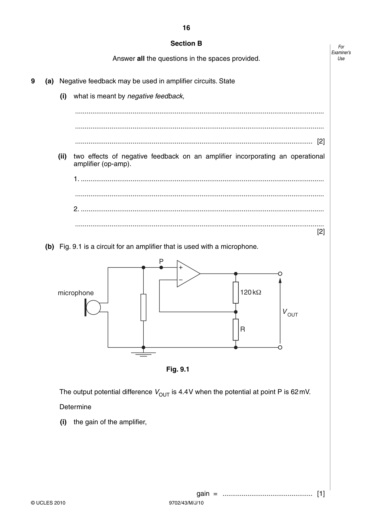
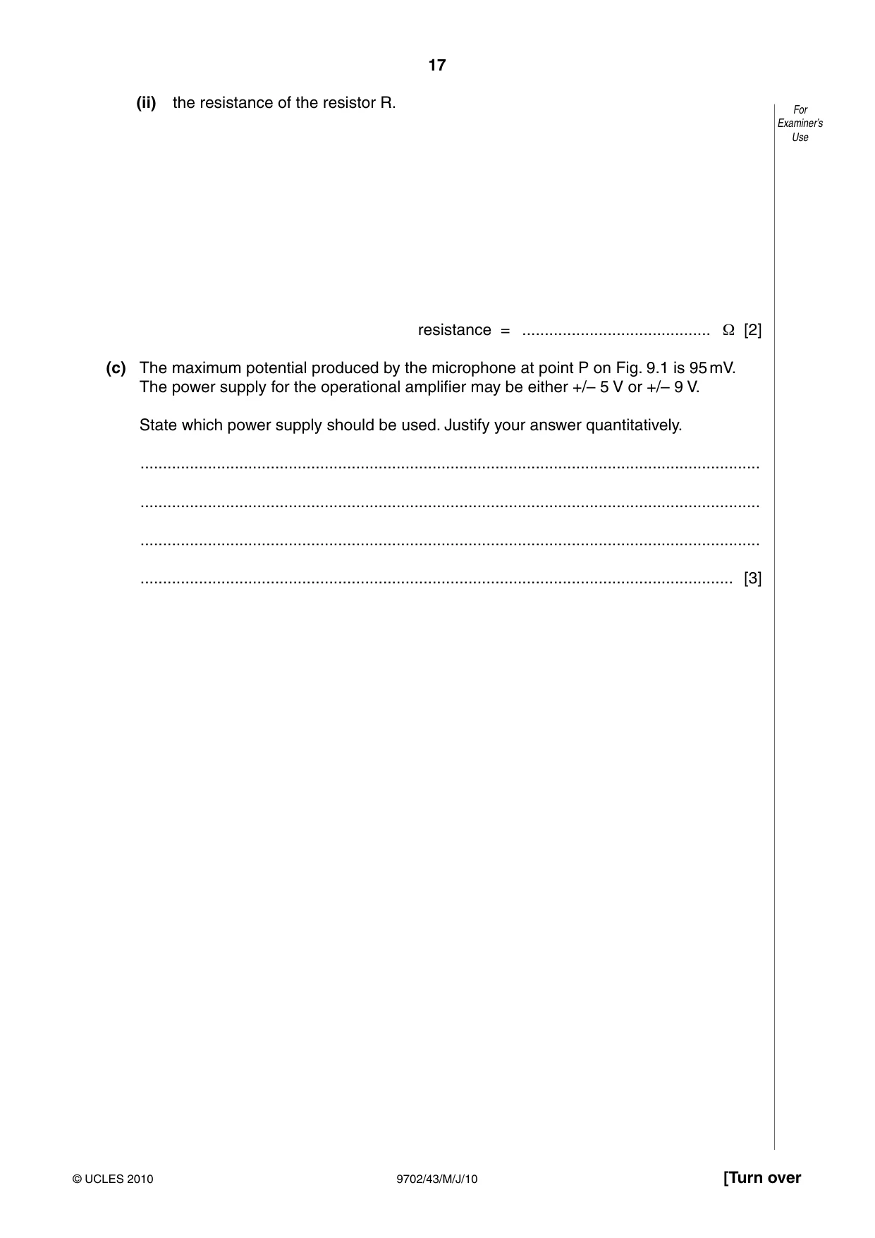
9 (a) Negative feedback may be used in amplifier circuits. State (i) what is meant by negative feedback, .................................................................................................................................. .................................................................................................................................. ............................................................................................................................ [2] (ii) two effects of negative feedback on an amplifier incorporating an operational amplifier (op-amp). 1. ............................................................................................................................... .................................................................................................................................. 2. ............................................................................................................................... .................................................................................................................................. [2] (b) Fig. 9.1 is a circuit for an amplifier that is used with a microphone. P microphone 120 kΩ V OUT R Fig. 9.1 The output potential difference VOUT is 4.4 V when the potential at point P is 62 mV. Determine (i) the gain of the amplifier, gain = ............................................... [1] (ii) the resistance of the resistor R. For Examiner’s Use resistance = .......................................... Ω [2] (c) The maximum potential produced by the microphone at point P on Fig. 9.1 is 95 mV. The power supply for the operational amplifier may be either +/– 5 V or +/– 9 V. State which power supply should be used. Justify your answer quantitatively. .......................................................................................................................................... .......................................................................................................................................... .......................................................................................................................................... .................................................................................................................................... [3]
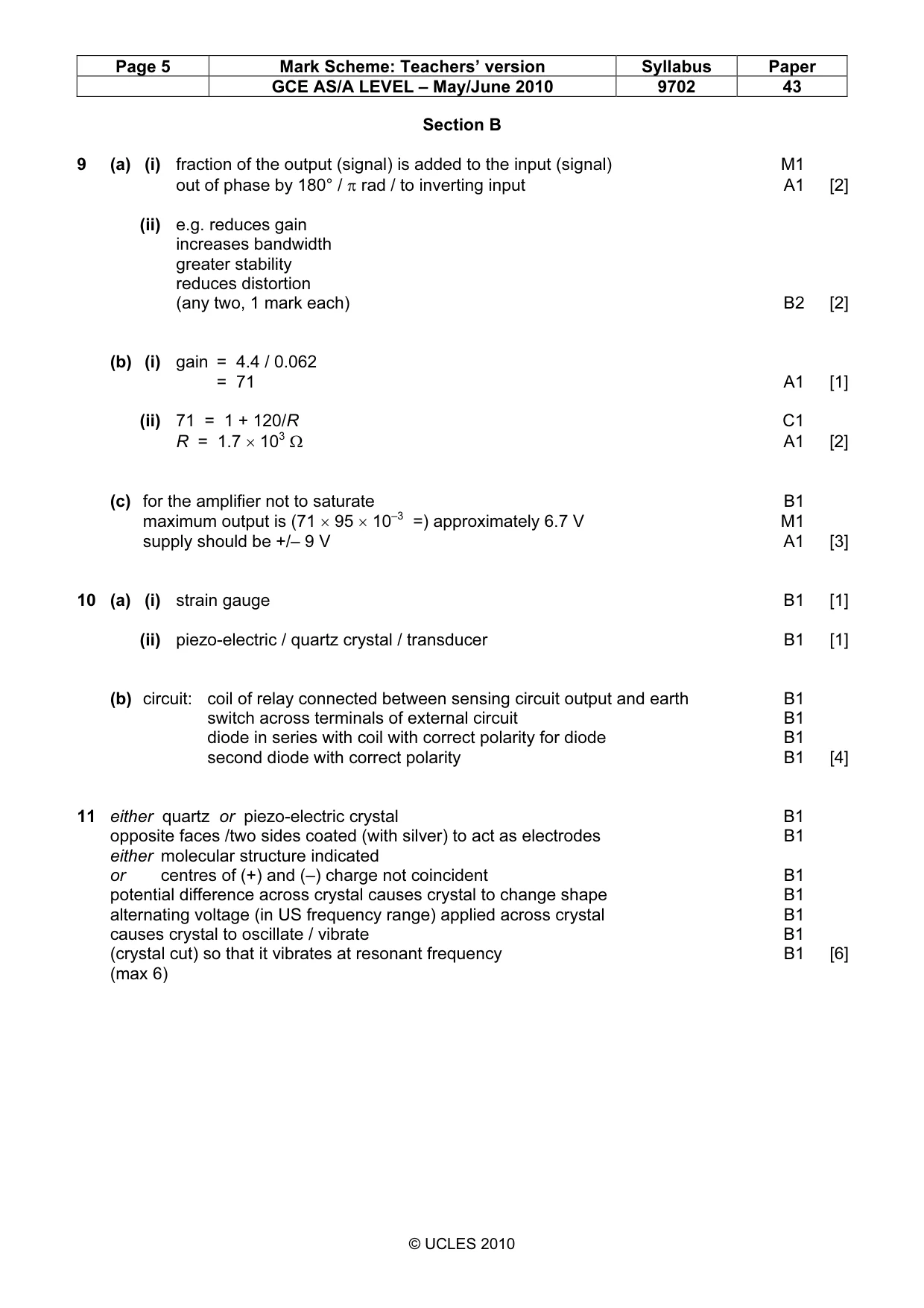
Mark scheme: 9 (a) (i) fraction of the output (signal) is added to the input (signal) M1 out of phase by 180° / π rad / to inverting input A1 [2] (ii) e.g. reduces gain increases bandwidth greater stability reduces distortion (any two, 1 mark each) B2 [2] (b) (i) gain = 4.4 / 0.062 = 71 A1 [1] (ii) 71 = 1 + 120/R C1 R = 1.7 × 10³ Ω A1 [2] (c) for the amplifier not to saturate B1 maximum output is (71 × 95 × 10–3 =) approximately 6.7 V M1 supply should be +/– 9 V A1 [3]
Q10 · State the name of an electrical sensing device that will respond to changes in For…
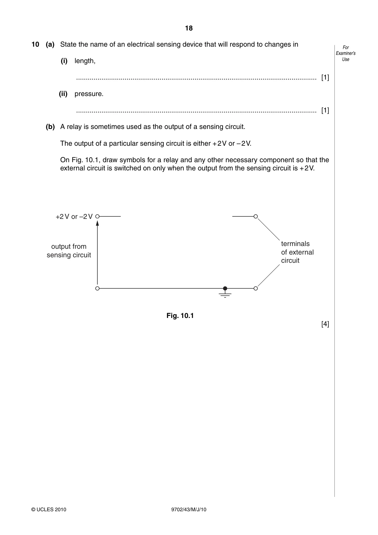
10 (a) State the name of an electrical sensing device that will respond to changes in For Examiner’s (i) length, Use ............................................................................................................................ [1] (ii) pressure. ............................................................................................................................ [1] (b) A relay is sometimes used as the output of a sensing circuit. The output of a particular sensing circuit is either + 2 V or – 2 V. On Fig. 10.1, draw symbols for a relay and any other necessary component so that the external circuit is switched on only when the output from the sensing circuit is + 2 V. +2 V or –2 V terminals output from of external sensing circuit circuit Fig. 10.1 [4]
Mark scheme: 10 (a) (i) strain gauge B1 [1] (ii) piezo-electric / quartz crystal / transducer B1 [1] (b) circuit: coil of relay connected between sensing circuit output and earth B1 switch across terminals of external circuit B1 diode in series with coil with correct polarity for diode B1 second diode with correct polarity B1 [4]
Q11 · Explain the main principles behind the generation of ultrasound to obtain diagnostic For…
11 Explain the main principles behind the generation of ultrasound to obtain diagnostic For information about internal body structures. Examiner’s Use ................................................................................................................................................. ................................................................................................................................................. ................................................................................................................................................. ................................................................................................................................................. ................................................................................................................................................. ................................................................................................................................................. ................................................................................................................................................. ................................................................................................................................................. ................................................................................................................................................. ................................................................................................................................................. ................................................................................................................................................. ................................................................................................................................................. ................................................................................................................................................. ........................................................................................................................................... [6]
Mark scheme: 11 either quartz or piezo-electric crystal B1 opposite faces /two sides coated (with silver) to act as electrodes B1 either molecular structure indicated or centres of (+) and (–) charge not coincident B1 potential difference across crystal causes crystal to change shape B1 alternating voltage (in US frequency range) applied across crystal B1 causes crystal to oscillate / vibrate B1 (crystal cut) so that it vibrates at resonant frequency B1 [6] (max 6) GCE AS/A LEVEL – May/June 2010 9702 43
Q12 · A telephone link between two towns is to be provided using an optic fibre
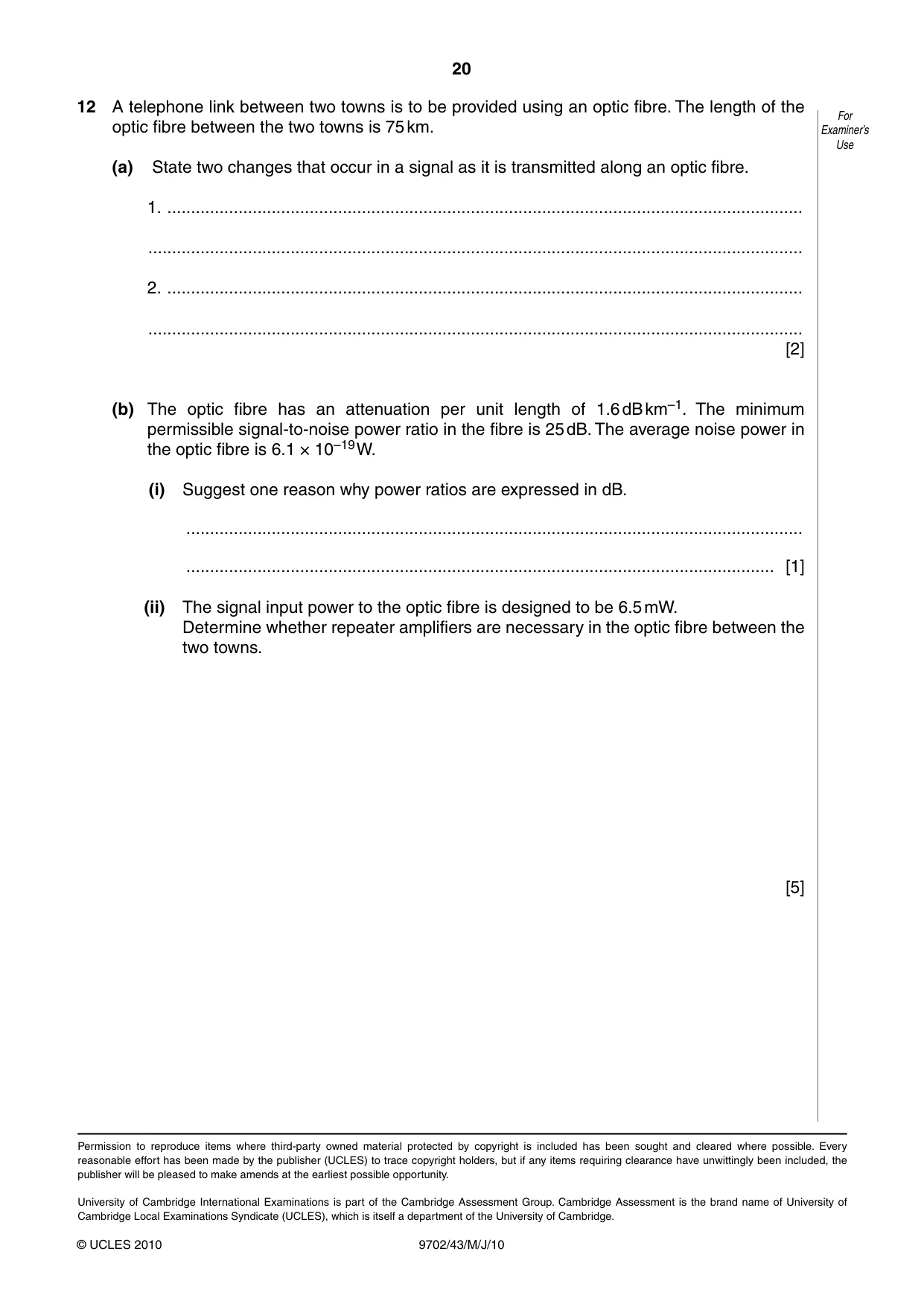
12 A telephone link between two towns is to be provided using an optic fibre. The length of the For optic fibre between the two towns is 75 km. Examiner’s Use (a) State two changes that occur in a signal as it is transmitted along an optic fibre. 1. ...................................................................................................................................... .......................................................................................................................................... 2. ...................................................................................................................................... .......................................................................................................................................... [2] (b) The optic fibre has an attenuation per unit length of 1.6 dB km–1. The minimum permissible signal-to-noise power ratio in the fibre is 25 dB. The average noise power in the optic fibre is 6.1 × 10⁻¹⁹ W. (i) Suggest one reason why power ratios are expressed in dB. .................................................................................................................................. ............................................................................................................................ [1] (ii) The signal input power to the optic fibre is designed to be 6.5 mW. Determine whether repeater amplifiers are necessary in the optic fibre between the two towns. [5]
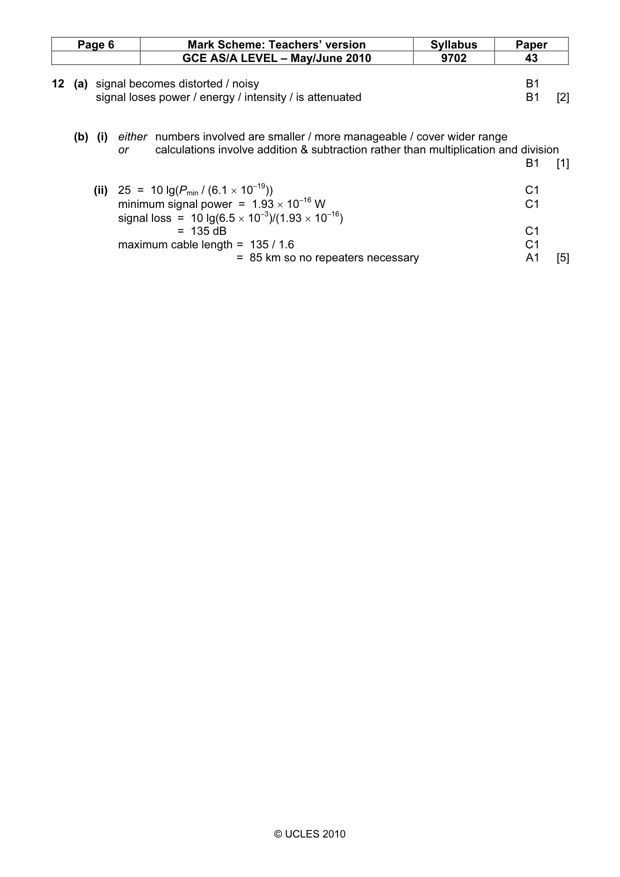
Mark scheme: 12 (a) signal becomes distorted / noisy B1 signal loses power / energy / intensity / is attenuated B1 [2] (b) (i) either numbers involved are smaller / more manageable / cover wider range or calculations involve addition & subtraction rather than multiplication and division B1 [1] (ii) 25 = 10 lg(Pmin / (6.1 × 10⁻¹⁹)) C1 minimum signal power = 1.93 × 10⁻¹⁶ W C1 signal loss = 10 lg(6.5 × 10⁻³)/(1.93 × 10–16) = 135 dB C1 maximum cable length = 135 / 1.6 C1 = 85 km so no repeaters necessary A1 [5]
What was in this paper
The subtopics covered by these 12 questions, and how many questions each got. Open one in a new tab to see every Cambridge question on it.
1Characteristics of alternating currents1Concept of a magnetic field1Electric potential1Gravitational potential1Physical quantities1Potential difference and power1Practical circuits1Production and use of ultrasound1Radioactive decay1Simple harmonic oscillations1Temperature scales1What you needed in this session
Cambridge’s own grade thresholds for 2010 May/June, Paper 4 · Variant 3. A higher threshold means an easier paper — the bar moves with how the cohort did.