Questions as text
Q1 · A uniform beam is clamped at one end 9702/42 Feb/March 2017
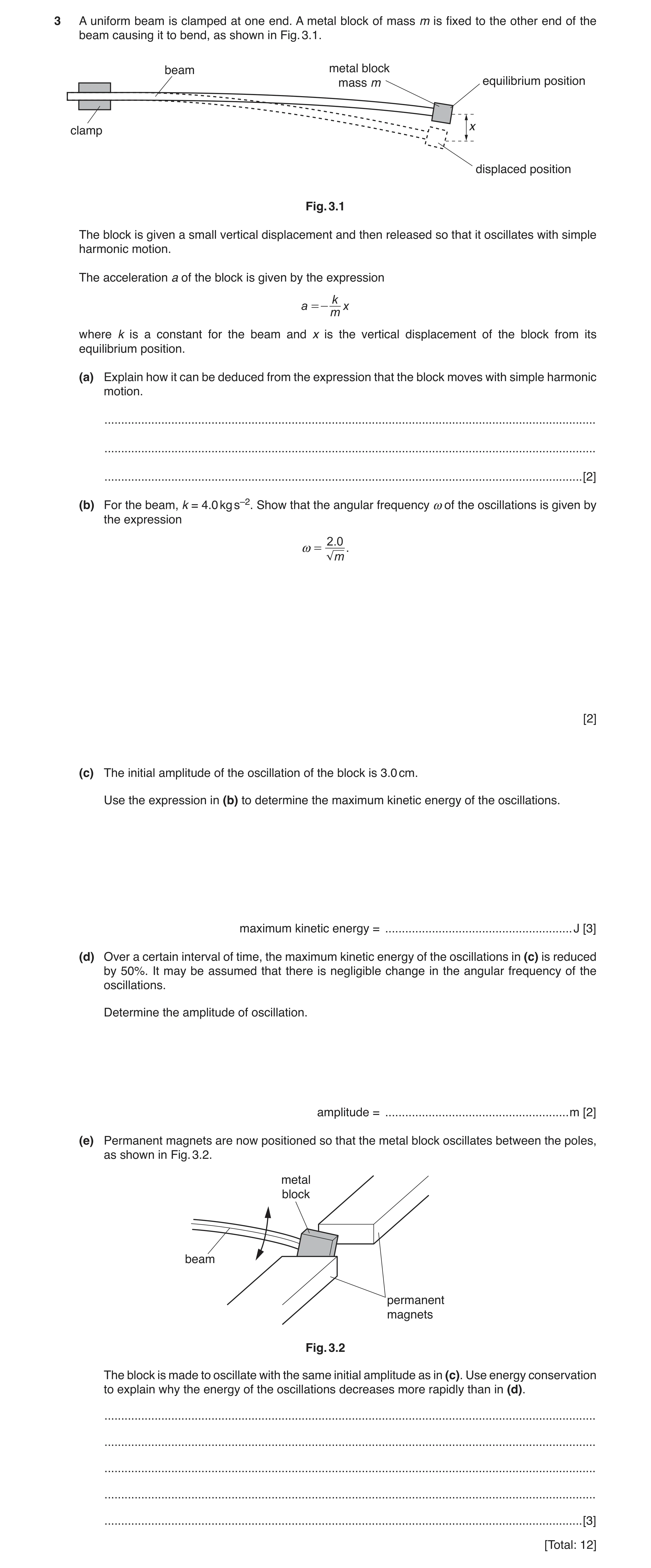
3 A uniform beam is clamped at one end. A metal block of mass m is fixed to the other end of the beam causing it to bend, as shown in Fig. 3.1. beam metal block mass m equilibrium position x clamp displaced position Fig. 3.1 The block is given a small vertical displacement and then released so that it oscillates with simple harmonic motion. The acceleration a of the block is given by the expression k a =- x m where k is a constant for the beam and x is the vertical displacement of the block from its equilibrium position. (a) Explain how it can be deduced from the expression that the block moves with simple harmonic motion. … … … [2] (b) For the beam, k = 4.0 kg s–2. Show that the angular frequency ω of the oscillations is given by the expression 2 .0 ω = . m [2] (c) The initial amplitude of the oscillation of the block is 3.0 cm. Use the expression in (b) to determine the maximum kinetic energy of the oscillations. maximum kinetic energy = … J [3] (d) Over a certain interval of time, the maximum kinetic energy of the oscillations in (c) is reduced by 50%. It may be assumed that there is negligible change in the angular frequency of the oscillations. Determine the amplitude of oscillation. amplitude = … m [2] (e) Permanent magnets are now positioned so that the metal block oscillates between the poles, as shown in Fig. 3.2. metal block beam permanent magnets Fig. 3.2 The block is made to oscillate with the same initial amplitude as in (c). Use energy conservation to explain why the energy of the oscillations decreases more rapidly than in (d). … … … … … [3] [Total: 12]
12 marks
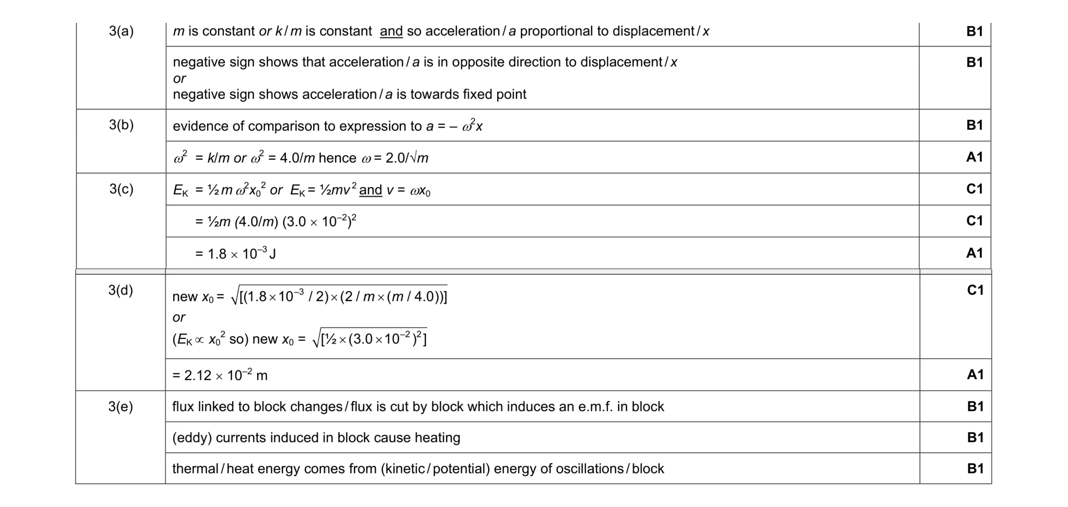
Mark scheme: 3(a) m is constant or k / m is constant and so acceleration / a proportional to displacement / x B1 negative sign shows that acceleration / a is in opposite direction to displacement / x or negative sign shows acceleration / a is towards fixed point B1 3(b) evidence of comparison to expression to a = – ω2x B1 ω2 = k/m or ω2 = 4.0/m hence ω = 2.0/√m A1 3(c) EK = ½ m ω2x0 2 or EK = ½mv 2 and v = ωx0 C1 = ½m (4.0/m) (3.0 × 10⁻²)2 C1 = 1.8 × 10⁻³ J A1 Question Answer Marks 3(d) new x0 = –3 [( ) ( 1.8 10 / 2 2 / ( / 4.0))] m m × × × or (EK ∝ x0 2 so) new x0 = –2 2 [½ 3.0 10 ( ) ] × × C1 = 2.12 × 10⁻² m A1 3(e) flux linked to block changes / flux is cut by block which induces an e.m.f. in block B1 (eddy) currents induced in block cause heating B1 thermal / heat energy comes from (kinetic / potential) energy of oscillations / block B1
This question in 9702/42 Feb/March 2017
Q2 · A bar magnet of mass 180 g is suspended from the free end of a spring, as illustrated in… 9702/41 May/June 2017
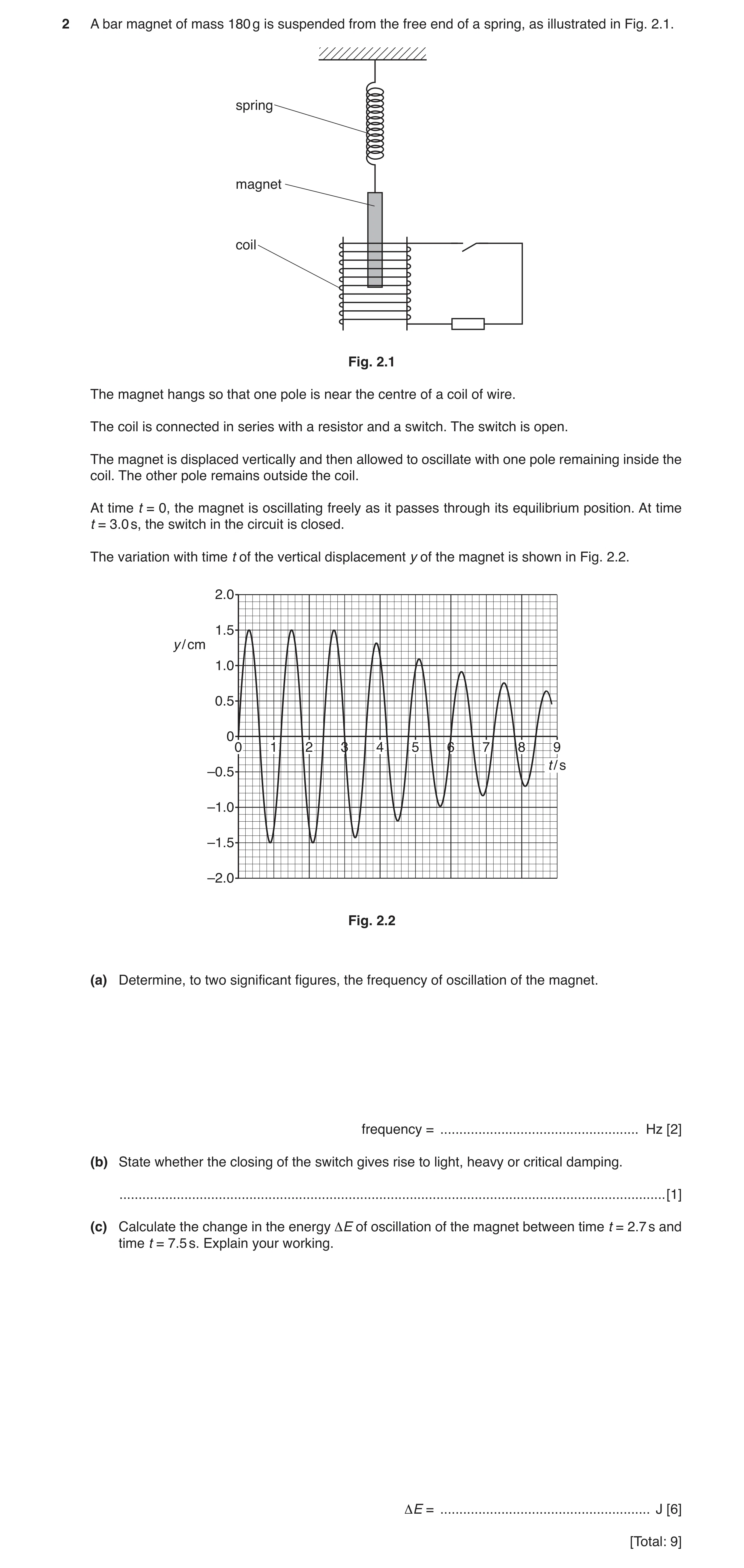
2 A bar magnet of mass 180 g is suspended from the free end of a spring, as illustrated in Fig. 2.1. spring magnet coil Fig. 2.1 The magnet hangs so that one pole is near the centre of a coil of wire. The coil is connected in series with a resistor and a switch. The switch is open. The magnet is displaced vertically and then allowed to oscillate with one pole remaining inside the coil. The other pole remains outside the coil. At time t = 0, the magnet is oscillating freely as it passes through its equilibrium position. At time t = 3.0 s, the switch in the circuit is closed. The variation with time t of the vertical displacement y of the magnet is shown in Fig. 2.2. 2.0 1.5 y / cm 1.0 0.5 0 0 1 2 3 4 5 6 7 8 9 t / s –0.5 –1.0 –1.5 –2.0 Fig. 2.2 (a) Determine, to two significant figures, the frequency of oscillation of the magnet. frequency = … Hz [2] (b) State whether the closing of the switch gives rise to light, heavy or critical damping. … [1] (c) Calculate the change in the energy ΔE of oscillation of the magnet between time t = 2.7 s and time t = 7.5 s. Explain your working. ΔE = … J [6] [Total: 9]
9 marks
Mark scheme: 2(a) e.g. period = 3 / 2.5 C1 frequency = 0.83 Hz A1 2(b) light (damping) B1 2(c) at 2.7 s, A0 = 1.5 (cm) B1 energy = ½ m × 4π2f 2A0 2 B1 = ½ × 0.18 × 4π2 × 0.832 × (1.5 × 10–2)2 = 5.51 × 10⁻⁴ (J) C1 at 7.5 s, A0 = 0.75 (cm) B1 energy = ¼ × 5.51 × 10⁻⁴ or energy = ½ × 0.18 × 4π2 × 0.832 × (0.75 × 10–2)2 C1 energy = 1.38 × 10⁻⁴ (J) change = (5.51 × 10⁻⁴ – 1.38 × 10⁻⁴) = 4.13 J A1
This question in 9702/41 May/June 2017
Q3 · A bar magnet of mass 250 g is suspended from the free end of a spring, as illustrated in… 9702/42 May/June 2017
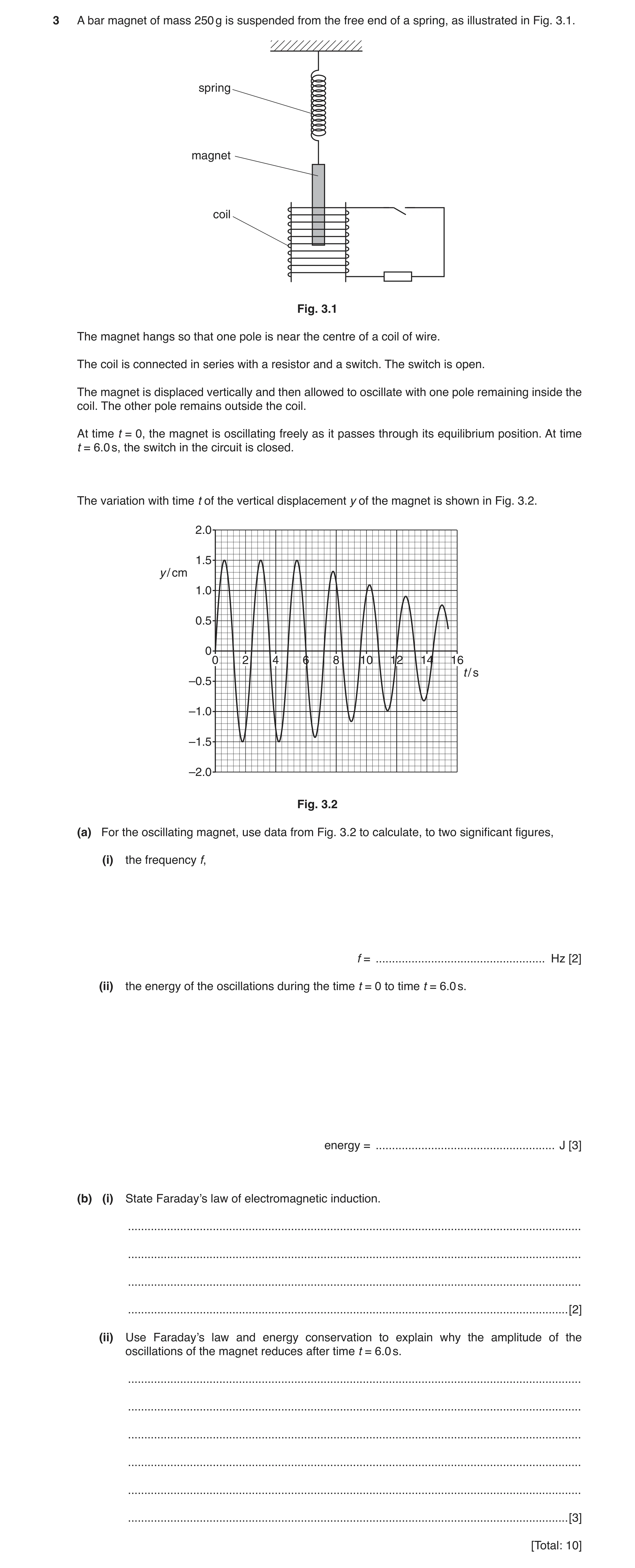
3 A bar magnet of mass 250 g is suspended from the free end of a spring, as illustrated in Fig. 3.1. spring magnet coil Fig. 3.1 The magnet hangs so that one pole is near the centre of a coil of wire. The coil is connected in series with a resistor and a switch. The switch is open. The magnet is displaced vertically and then allowed to oscillate with one pole remaining inside the coil. The other pole remains outside the coil. At time t = 0, the magnet is oscillating freely as it passes through its equilibrium position. At time t = 6.0 s, the switch in the circuit is closed. The variation with time t of the vertical displacement y of the magnet is shown in Fig. 3.2. 2.0 1.5 y / cm 1.0 0.5 0 0 2 4 6 8 10 12 14 16 t / s –0.5 –1.0 –1.5 –2.0 Fig. 3.2 (a) For the oscillating magnet, use data from Fig. 3.2 to calculate, to two significant figures, (i) the frequency f, f = … Hz [2] (ii) the energy of the oscillations during the time t = 0 to time t = 6.0 s. energy = … J [3] (b) (i) State Faraday’s law of electromagnetic induction. … … … … [2] (ii) Use Faraday’s law and energy conservation to explain why the amplitude of the oscillations of the magnet reduces after time t = 6.0 s. … … … … … … [3] [Total: 10]
10 marks
Mark scheme: 3(a)(i) e.g. period = 6 / 2.5 C1 frequency = 0.42 Hz A1 3(a)(ii) energy = ½ m × 4π2f 2y0 2 C1 = ½ × 0.25 × 4π2 × 0.422 × (1.5 × 10–2)2 C1 = 2.0 × 10⁻⁴ J A1 3(b)(i) (induced) e.m.f. proportional to rate of M1 change of magnetic flux (linkage) or cutting of magnetic flux A1 3(b)(ii) coil cuts flux/field (of moving magnet) inducing e.m.f. in coil B1 (induced) current in resistor causes heating (effect) M1 thermal energy/heat derived from energy of oscillations (of magnet) A1
This question in 9702/42 May/June 2017
Q4 · A bar magnet of mass 180 g is suspended from the free end of a spring, as illustrated in… 9702/43 May/June 2017
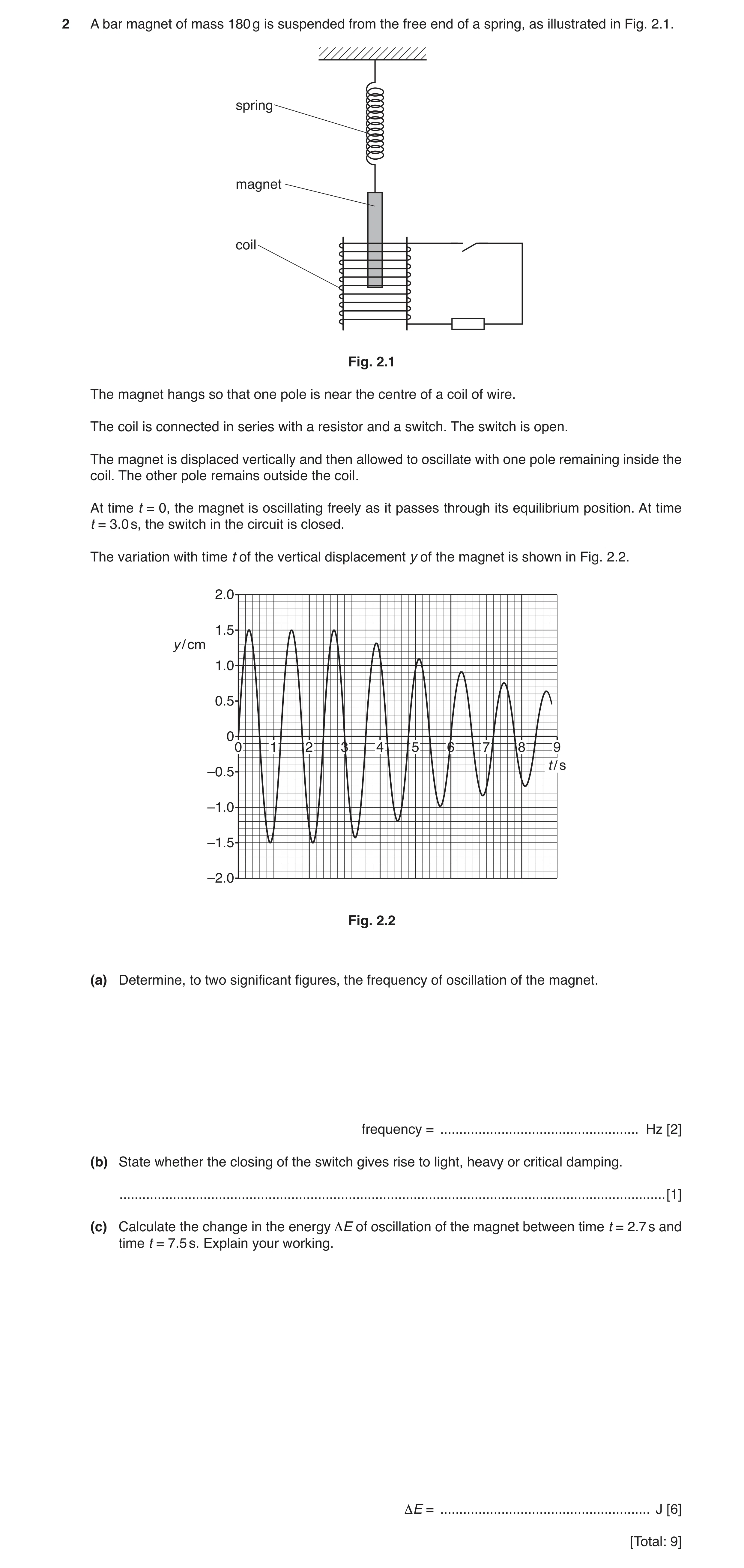
2 A bar magnet of mass 180 g is suspended from the free end of a spring, as illustrated in Fig. 2.1. spring magnet coil Fig. 2.1 The magnet hangs so that one pole is near the centre of a coil of wire. The coil is connected in series with a resistor and a switch. The switch is open. The magnet is displaced vertically and then allowed to oscillate with one pole remaining inside the coil. The other pole remains outside the coil. At time t = 0, the magnet is oscillating freely as it passes through its equilibrium position. At time t = 3.0 s, the switch in the circuit is closed. The variation with time t of the vertical displacement y of the magnet is shown in Fig. 2.2. 2.0 1.5 y / cm 1.0 0.5 0 0 1 2 3 4 5 6 7 8 9 t / s –0.5 –1.0 –1.5 –2.0 Fig. 2.2 (a) Determine, to two significant figures, the frequency of oscillation of the magnet. frequency = … Hz [2] (b) State whether the closing of the switch gives rise to light, heavy or critical damping. … [1] (c) Calculate the change in the energy ΔE of oscillation of the magnet between time t = 2.7 s and time t = 7.5 s. Explain your working. ΔE = … J [6] [Total: 9]
9 marks
Mark scheme: 2(a) e.g. period = 3 / 2.5 C1 frequency = 0.83 Hz A1 2(b) light (damping) B1 2(c) at 2.7 s, A0 = 1.5 (cm) B1 energy = ½ m × 4π2f 2A0 2 B1 = ½ × 0.18 × 4π2 × 0.832 × (1.5 × 10–2)2 = 5.51 × 10⁻⁴ (J) C1 at 7.5 s, A0 = 0.75 (cm) B1 energy = ¼ × 5.51 × 10⁻⁴ or energy = ½ × 0.18 × 4π2 × 0.832 × (0.75 × 10–2)2 C1 energy = 1.38 × 10⁻⁴ (J) change = (5.51 × 10⁻⁴ – 1.38 × 10⁻⁴) = 4.13 J A1
This question in 9702/43 May/June 2017
Q5 · A spring is hung vertically from a fixed point 9702/42 May/June 2019
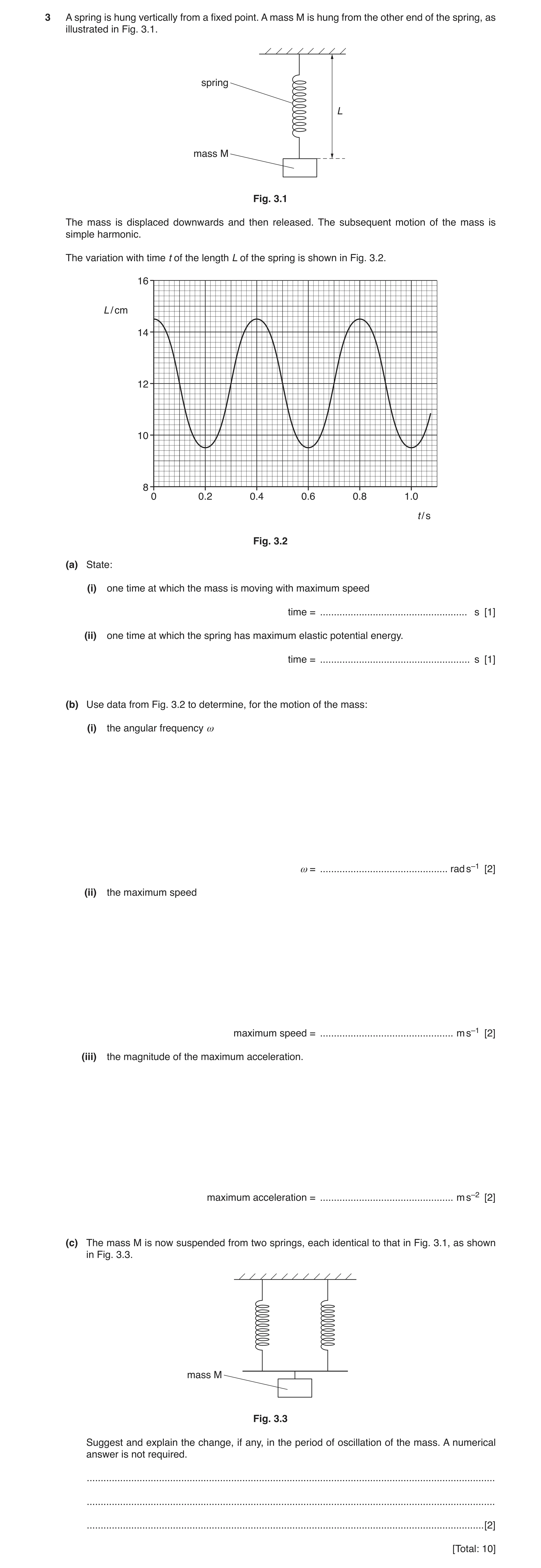
3 A spring is hung vertically from a fixed point. A mass M is hung from the other end of the spring, as illustrated in Fig. 3.1. spring L mass M Fig. 3.1 The mass is displaced downwards and then released. The subsequent motion of the mass is simple harmonic. The variation with time t of the length L of the spring is shown in Fig. 3.2. 16 L / cm 14 12 10 8 0 0.2 0.4 0.6 0.8 1.0 t / s Fig. 3.2 (a) State: (i) one time at which the mass is moving with maximum speed time = … s [1] (ii) one time at which the spring has maximum elastic potential energy. time = … s [1] (b) Use data from Fig. 3.2 to determine, for the motion of the mass: (i) the angular frequency ω ω = … rad s–1 [2] (ii) the maximum speed maximum speed = … m s–1 [2] (iii) the magnitude of the maximum acceleration. maximum acceleration = … m s–2 [2] (c) The mass M is now suspended from two springs, each identical to that in Fig. 3.1, as shown in Fig. 3.3. mass M Fig. 3.3 Suggest and explain the change, if any, in the period of oscillation of the mass. A numerical answer is not required. … … … [2] [Total: 10]
10 marks
Mark scheme: 3(a)(i) 0.10 s or 0.30 s or 0.50 s or 0.70 s or 0.90 s A1 3(a)(ii) 0 or 0.40 s or 0.80 s A1 3(b)(i) ω = 2π / T C1 = 2π / 0.40 = 16 rad s–1 A1 3(b)(ii) v0 = ωx0 C1 = 15.7 × 2.5 × 10–2 = 0.39 m s–1 A1 or tangent drawn at steepest part and working to show attempted calculation of gradient (C1) leading to v0 = 0.39 m s–1 (allow ± 0.15 m s–1) (A1) 3(b)(iii) a0 = ω 2x0 C1 a0 = (15.72 × 2.5 × 10–2) = 6.2 m s–2 A1 or a0 = ωv0 (C1) a0 = 15.7 × 0.39 = 6.2 m s–2 (A1) Question Answer Marks 3(c) period is shorter/lower B1 Any one from: • greater spring constant/stiffness • (restoring) force is greater (for any given extension) • acceleration is greater (for any given extension) • greater energy/maximum speed (for a given amplitude) B1
This question in 9702/42 May/June 2019
Q6 · A simple pendulum consists of a metal sphere suspended from a fixed point by means of a… 9702/42 Oct/Nov 2020
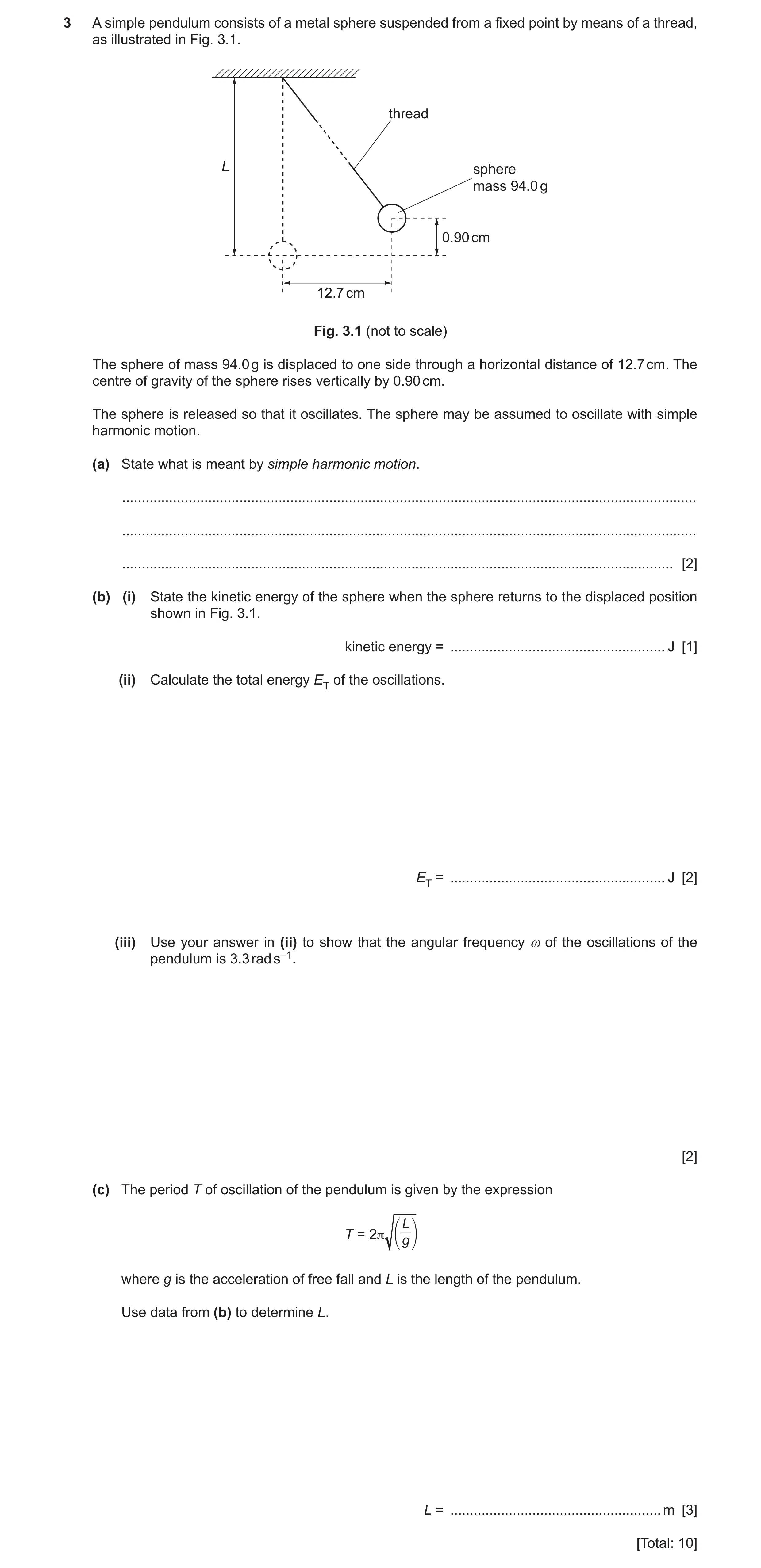
3 A simple pendulum consists of a metal sphere suspended from a fixed point by means of a thread, as illustrated in Fig. 3.1. thread L sphere mass 94.0 g 0.90 cm 12.7 cm Fig. 3.1 (not to scale) The sphere of mass 94.0 g is displaced to one side through a horizontal distance of 12.7 cm. The centre of gravity of the sphere rises vertically by 0.90 cm. The sphere is released so that it oscillates. The sphere may be assumed to oscillate with simple harmonic motion. (a) State what is meant by simple harmonic motion. … … … [2] (b) (i) State the kinetic energy of the sphere when the sphere returns to the displaced position shown in Fig. 3.1. kinetic energy = … J [1] (ii) Calculate the total energy ET of the oscillations. ET = … J [2] (iii) Use your answer in (ii) to show that the angular frequency ω of the oscillations of the pendulum is 3.3 rad s–1. [2] (c) The period T of oscillation of the pendulum is given by the expression L T = 2π g where g is the acceleration of free fall and L is the length of the pendulum. Use data from (b) to determine L. L = … m [3] [Total: 10]
10 marks
Mark scheme: 3(a) acceleration (directly) proportional to displacement B1 acceleration is in opposite direction to displacement or acceleration is (directed) towards a fixed point B1 3(b)(i) zero B1 3(b)(ii) ET is maximum potential energy = mgh ET = 94 × 10–3 × 9.81 × 0.90 × 10–2 C1 = 8.3 × 10⁻³ J A1 3(b)(iii) EMAX = ½ mv02 and v0 = ωx0 or EMAX = ½m(ωx0)2 C1 8.3 × 10–3 = ½ × 94 × 10–3 × ω2 × (12.7 × 10–2)2 …leading to ω = 3.3 rad s–1 A1 3(c) T = 2π / ω C1 2π / 3.3 = 2π × (L / 9.81)½ C1 L = 0.90 m A1
This question in 9702/42 Oct/Nov 2020
Q7 · A U-shaped tube contains some liquid 9702/42 May/June 2021
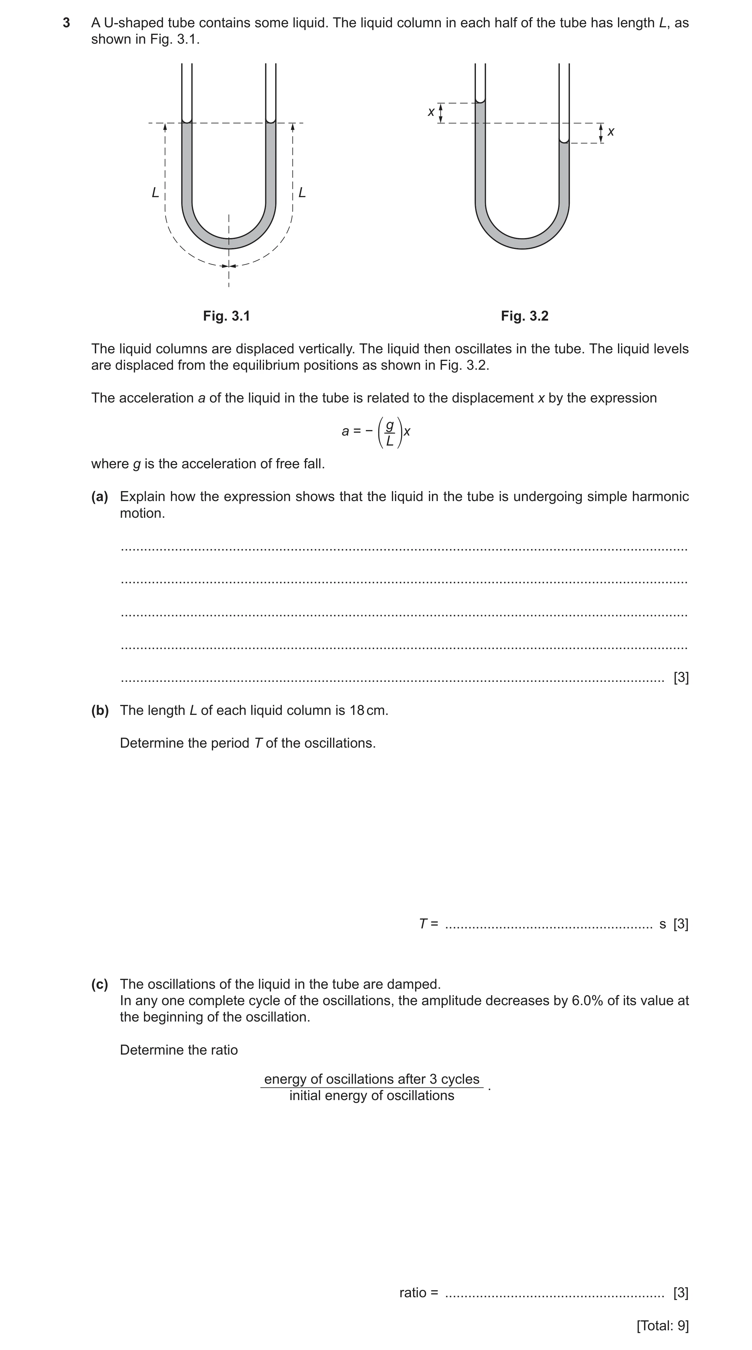
3 A U-shaped tube contains some liquid. The liquid column in each half of the tube has length L, as shown in Fig. 3.1. x x L L Fig. 3.1 Fig. 3.2 The liquid columns are displaced vertically. The liquid then oscillates in the tube. The liquid levels are displaced from the equilibrium positions as shown in Fig. 3.2. The acceleration a of the liquid in the tube is related to the displacement x by the expression ⎛ g ⎞ a = − x ⎝ L ⎠ where g is the acceleration of free fall. (a) Explain how the expression shows that the liquid in the tube is undergoing simple harmonic motion. … … … … … [3] (b) The length L of each liquid column is 18 cm. Determine the period T of the oscillations. T = … s [3] (c) The oscillations of the liquid in the tube are damped. In any one complete cycle of the oscillations, the amplitude decreases by 6.0% of its value at the beginning of the oscillation. Determine the ratio energy of oscillations after 3 cycles . initial energy of oscillations ratio = … [3] [Total: 9]
9 marks
Mark scheme: 3(a) acceleration in opposite direction to displacement shown by – sign B1 g / L is constant M1 (so) acceleration is (directly) proportional to displacement A1 3(b) ω2 = g / L C1 ω = 2π / T or ω = 2πf and f = 1 / T C1 (2π / T)2 = 9.81 / 0.18 T = 0.85 s A1 3(c) energy ∝ x02 C1 (after 3 cycles,) amplitude = (0.94)3x0 = 0.83x0 C1 ratio final energy / initial energy = 0.832 = 0.69 A1
This question in 9702/42 May/June 2021
Q8 · A trolley on a smooth surface is attached by springs to fixed blocks as shown in Fig 9702/42 Oct/Nov 2021
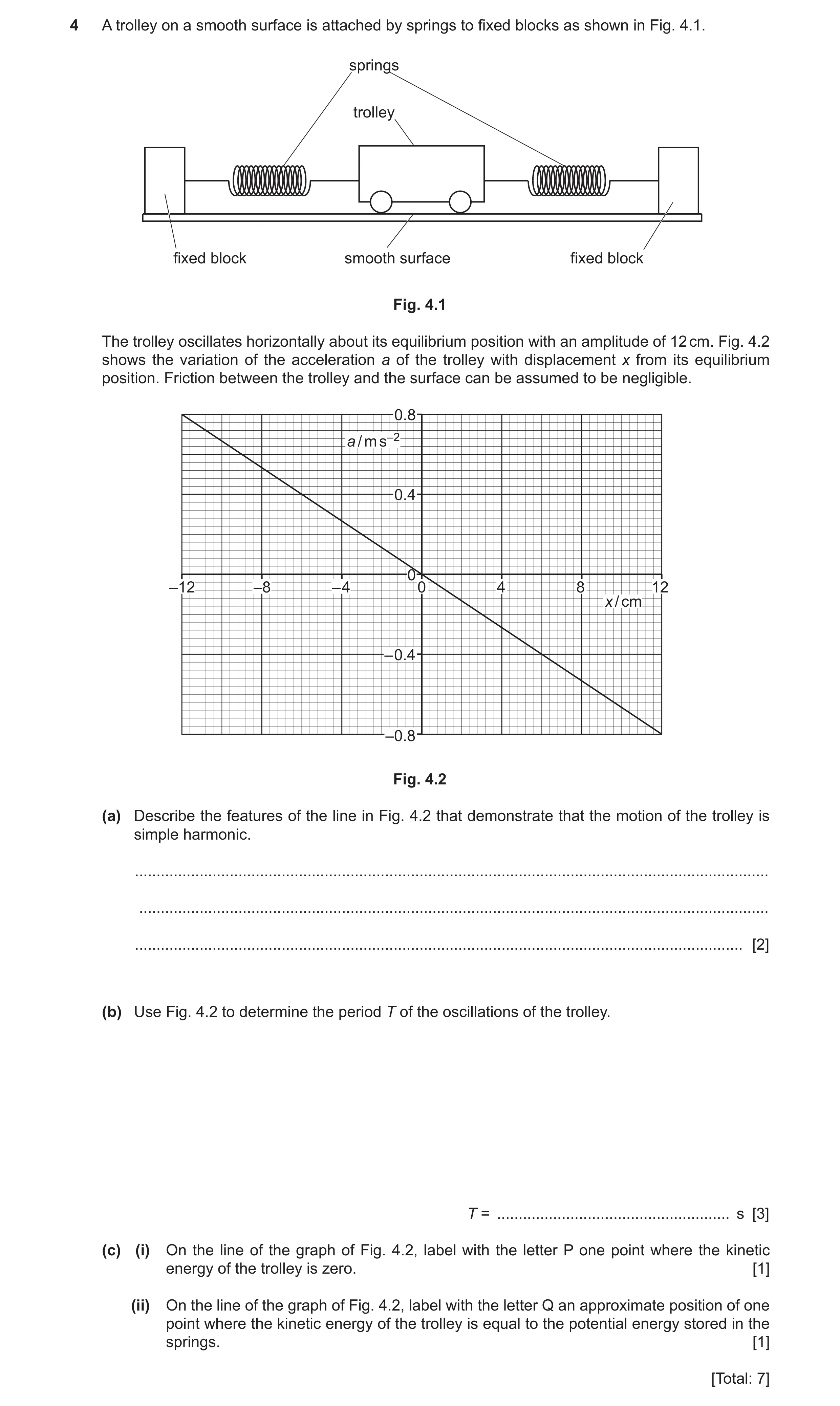
4 A trolley on a smooth surface is attached by springs to fixed blocks as shown in Fig. 4.1. springs trolley fixed block smooth surface fixed block Fig. 4.1 The trolley oscillates horizontally about its equilibrium position with an amplitude of 12 cm. Fig. 4.2 shows the variation of the acceleration a of the trolley with displacement x from its equilibrium position. Friction between the trolley and the surface can be assumed to be negligible. 0.8 a / m s–2 0.4 0 –12 –8 – 4 0 4 8 12 x / cm – 0.4 –0.8 Fig. 4.2 (a) Describe the features of the line in Fig. 4.2 that demonstrate that the motion of the trolley is simple harmonic. … … … [2] (b) Use Fig. 4.2 to determine the period T of the oscillations of the trolley. T = … s [3] (c) (i) On the line of the graph of Fig. 4.2, label with the letter P one point where the kinetic energy of the trolley is zero. [1] (ii) On the line of the graph of Fig. 4.2, label with the letter Q an approximate position of one point where the kinetic energy of the trolley is equal to the potential energy stored in the springs. [1] [Total: 7]
7 marks
Mark scheme: 4(a) straight line through the origin B1 negative gradient B1 4(b) a = (–)ω2x and T = 2π / ω C1 e.g. ω = √(0.80 / 0.12) (any correct pair of values of a and x) ( = 2.58 rad s–1) C1 T = 2π / 2.58 = 2.4 s A1 4(c)(i) Point labelled P at one end of the line B1 4(c)(ii) Point labelled Q at displacement with magnitude more than half but less than maximum B1
This question in 9702/42 Oct/Nov 2021
Q9 · A pendulum consists of a bob (small metal sphere) attached to the end of a piece of string 9702/41 May/June 2022
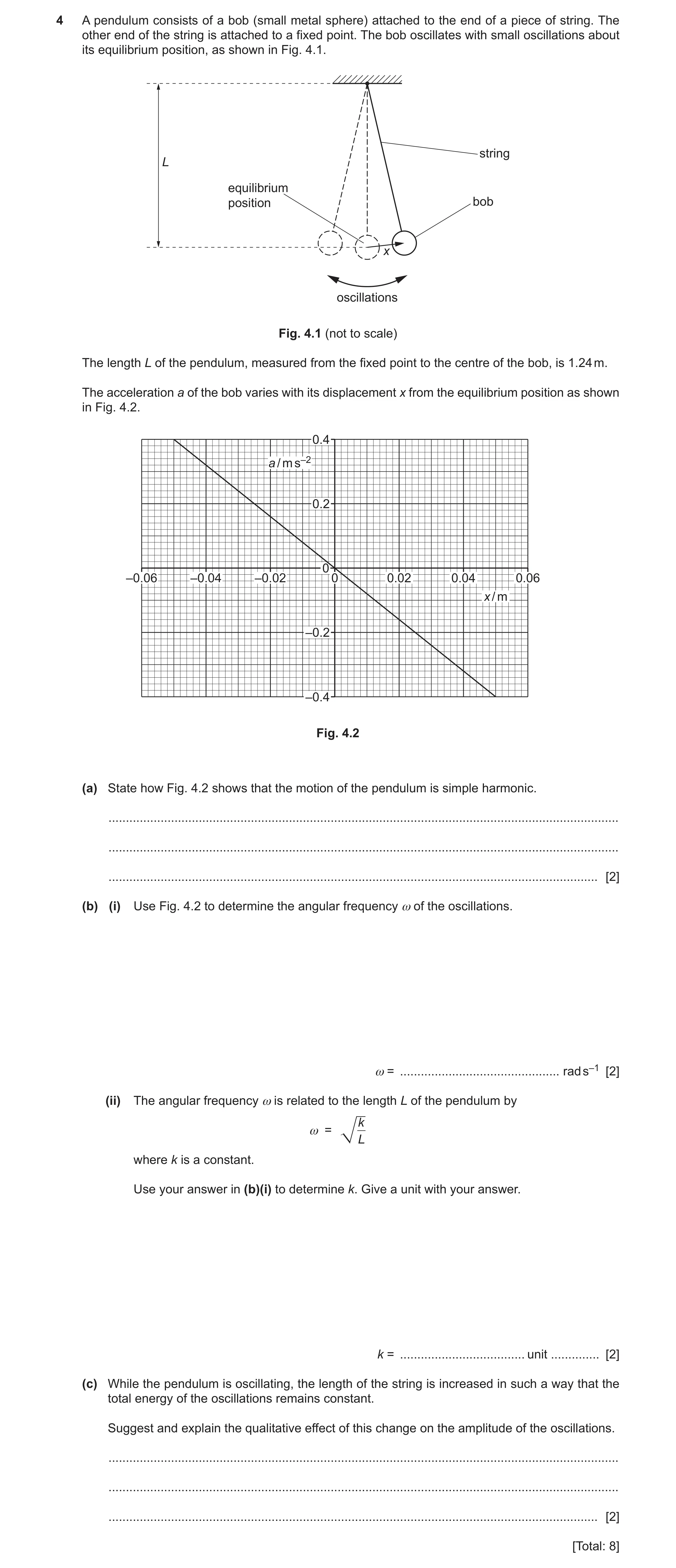
4 A pendulum consists of a bob (small metal sphere) attached to the end of a piece of string. The other end of the string is attached to a fixed point. The bob oscillates with small oscillations about its equilibrium position, as shown in Fig. 4.1. string L equilibrium position bob x oscillations Fig. 4.1 (not to scale) The length L of the pendulum, measured from the fixed point to the centre of the bob, is 1.24 m. The acceleration a of the bob varies with its displacement x from the equilibrium position as shown in Fig. 4.2. 0.4 a / m s–2 0.2 0 –0.06 –0.04 –0.02 0 0.02 0.04 0.06 x / m –0.2 –0.4 Fig. 4.2 (a) State how Fig. 4.2 shows that the motion of the pendulum is simple harmonic. … … … [2] (b) (i) Use Fig. 4.2 to determine the angular frequency ω of the oscillations. ω = … rad s–1 [2] (ii) The angular frequency ω is related to the length L of the pendulum by k ω = L where k is a constant. Use your answer in (b)(i) to determine k. Give a unit with your answer. k = … unit … [2] (c) While the pendulum is oscillating, the length of the string is increased in such a way that the total energy of the oscillations remains constant. Suggest and explain the qualitative effect of this change on the amplitude of the oscillations. … … … [2] [Total: 8]
8 marks
Mark scheme: 4(a) straight line through origin shows that a is proportional to x B1 negative gradient shows that a is in opposite direction to x B1 4(b)(i) a0 = 2x0 or a = – 2x or 2 = – gradient C1 = (0.40 / 0.050) = 2.8 rad s–1 A1 4(b)(ii) k = 2L = 2.82 1.24 C1 = 9.7 m s–2 A1 4(c) (increasing L causes) to decrease or energy (= ½ m2x02) = ½ mkx02 / L (and L increases) M1 so amplitude increases A1
This question in 9702/41 May/June 2022
Q10 · A pendulum consists of a bob (small metal sphere) attached to the end of a piece of string 9702/43 May/June 2022
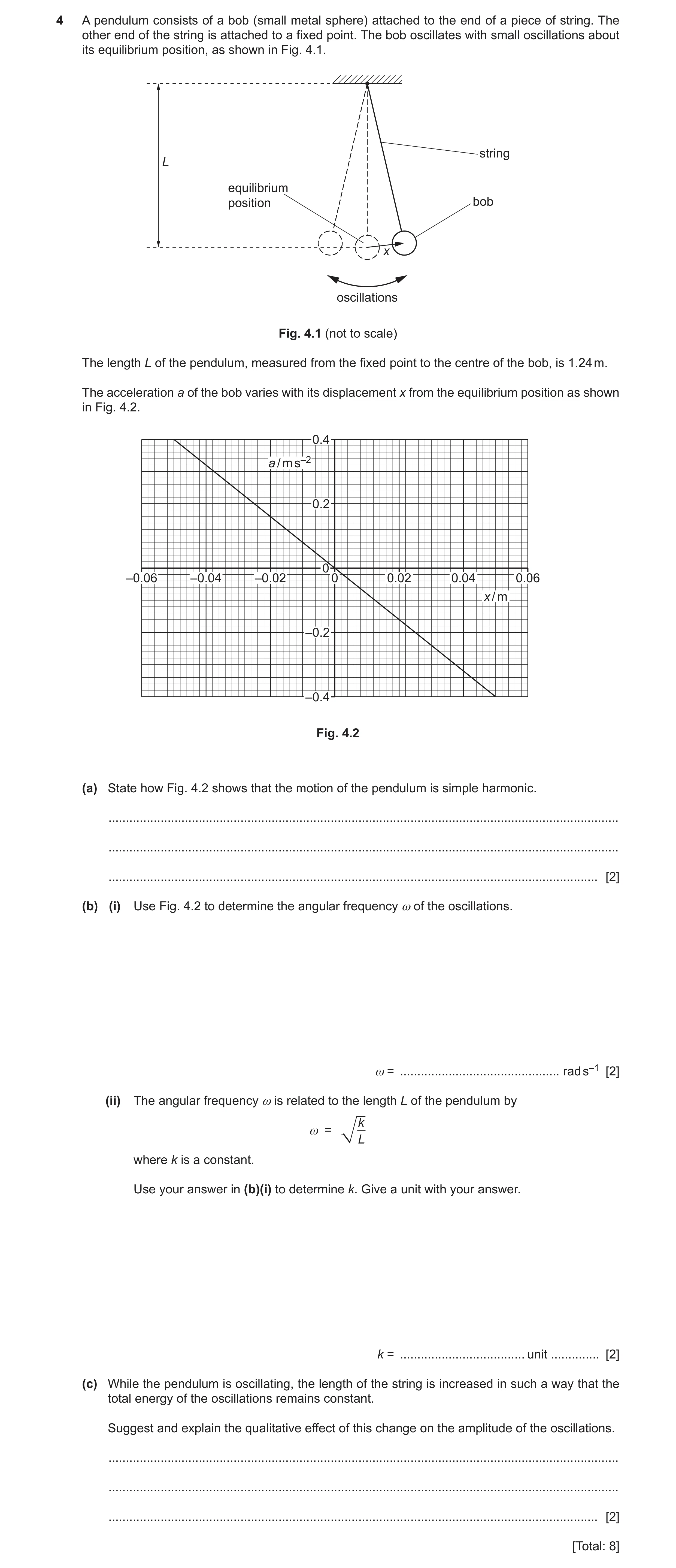
4 A pendulum consists of a bob (small metal sphere) attached to the end of a piece of string. The other end of the string is attached to a fixed point. The bob oscillates with small oscillations about its equilibrium position, as shown in Fig. 4.1. string L equilibrium position bob x oscillations Fig. 4.1 (not to scale) The length L of the pendulum, measured from the fixed point to the centre of the bob, is 1.24 m. The acceleration a of the bob varies with its displacement x from the equilibrium position as shown in Fig. 4.2. 0.4 a / m s–2 0.2 0 –0.06 –0.04 –0.02 0 0.02 0.04 0.06 x / m –0.2 –0.4 Fig. 4.2 (a) State how Fig. 4.2 shows that the motion of the pendulum is simple harmonic. … … … [2] (b) (i) Use Fig. 4.2 to determine the angular frequency ω of the oscillations. ω = … rad s–1 [2] (ii) The angular frequency ω is related to the length L of the pendulum by k ω = L where k is a constant. Use your answer in (b)(i) to determine k. Give a unit with your answer. k = … unit … [2] (c) While the pendulum is oscillating, the length of the string is increased in such a way that the total energy of the oscillations remains constant. Suggest and explain the qualitative effect of this change on the amplitude of the oscillations. … … … [2] [Total: 8]
8 marks
Mark scheme: 4(a) straight line through origin shows that a is proportional to x B1 negative gradient shows that a is in opposite direction to x B1 4(b)(i) a0 = 2x0 or a = – 2x or 2 = – gradient C1 = (0.40 / 0.050) = 2.8 rad s–1 A1 4(b)(ii) k = 2L = 2.82 1.24 C1 = 9.7 m s–2 A1 4(c) (increasing L causes) to decrease or energy (= ½ m2x02) = ½ mkx02 / L (and L increases) M1 so amplitude increases A1
This question in 9702/43 May/June 2022
Q11 · An object is suspended from a vertical spring as shown in Fig 9702/42 Feb/March 2023
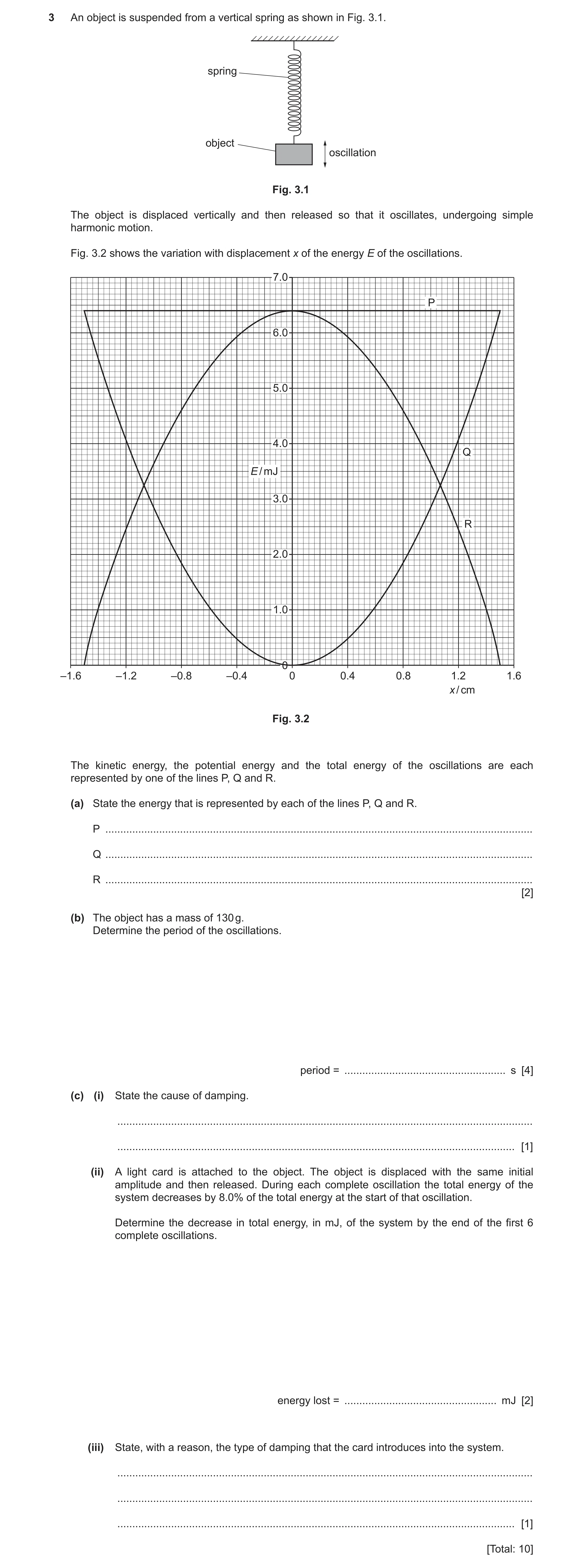
3 An object is suspended from a vertical spring as shown in Fig. 3.1. spring object oscillation Fig. 3.1 The object is displaced vertically and then released so that it oscillates, undergoing simple harmonic motion. Fig. 3.2 shows the variation with displacement x of the energy E of the oscillations. 7.0 P 6.0 5.0 4.0 Q E / mJ 3.0 R 2.0 1.0 0 –1.6 –1.2 –0.8 –0.4 0 0.4 0.8 1.2 1.6 x / cm Fig. 3.2 The kinetic energy, the potential energy and the total energy of the oscillations are each represented by one of the lines P, Q and R. (a) State the energy that is represented by each of the lines P, Q and R. P … Q … R … [2] (b) The object has a mass of 130 g. Determine the period of the oscillations. period = … s [4] (c) (i) State the cause of damping. … … [1] (ii) A light card is attached to the object. The object is displaced with the same initial amplitude and then released. During each complete oscillation the total energy of the system decreases by 8.0% of the total energy at the start of that oscillation. Determine the decrease in total energy, in mJ, of the system by the end of the first 6 complete oscillations. energy lost = … mJ [2] (iii) State, with a reason, the type of damping that the card introduces into the system. … … … [1] [Total: 10]
10 marks
Mark scheme: 3(a) P: total energy B2 Q: potential energy R: kinetic energy 3(b) E = ½m2x02 or E = ½mv02 and v0 = x0 C1 6.4 10 −3 = 1 0.130 2 0.0152 C1 2 (2 = 438) (= 20.9) T = 2 / C1 = 2 / 20.9 A1 = 0.30 s 3(c)(i) resistive forces B1 3(c)(ii) 0.926 C1 decrease in energy = 6.4 – (6.4 0.926) A1 = 2.5 mJ 3(c)(iii) light damping because the amplitude of oscillations gradually reduces B1 or light damping because the system still oscillates
This question in 9702/42 Feb/March 2023
Q12 · A small steel sphere is oscillating vertically on the end of a spring, as shown in Fig 9702/42 May/June 2023
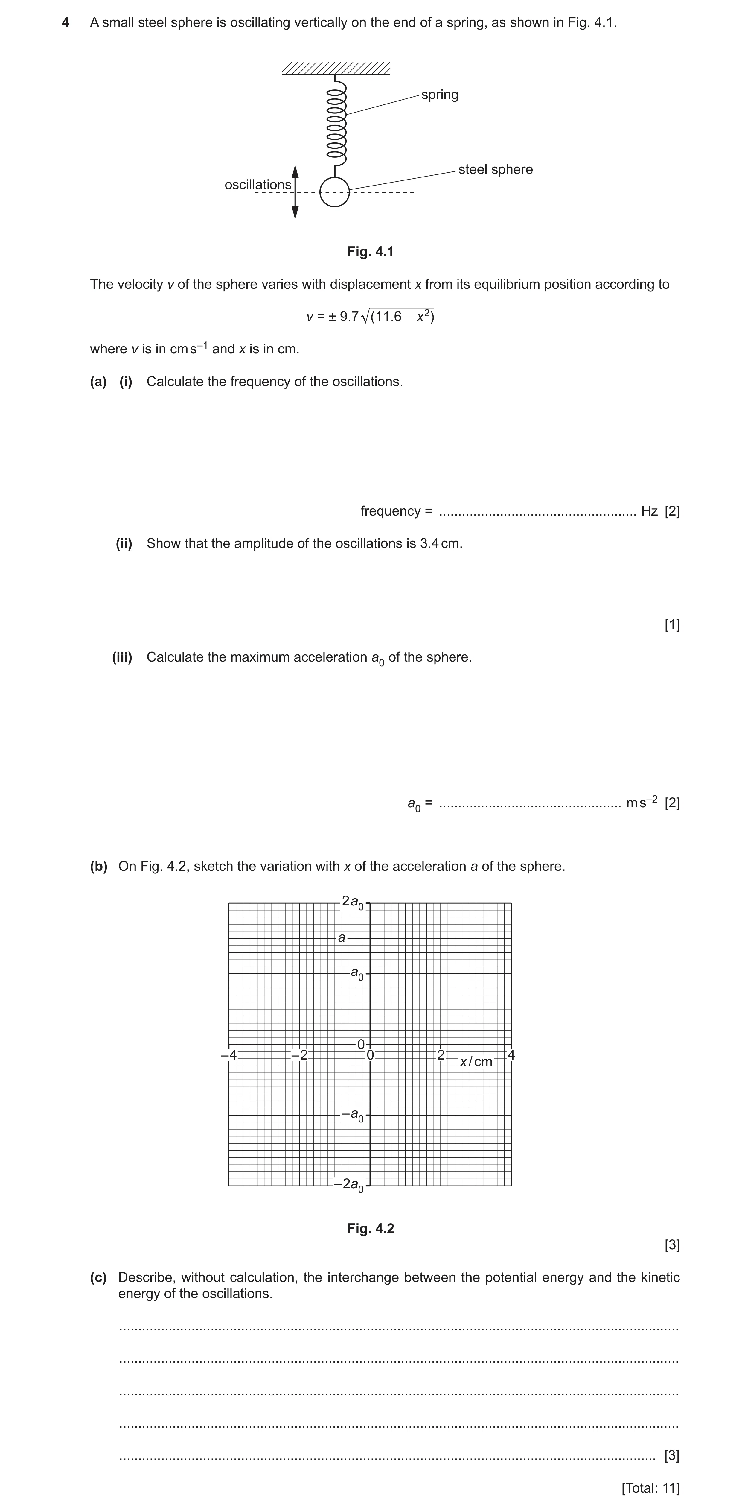
4 A small steel sphere is oscillating vertically on the end of a spring, as shown in Fig. 4.1. spring steel sphere oscillations Fig. 4.1 The velocity v of the sphere varies with displacement x from its equilibrium position according to v = ± 9.7 (11 .6 - x 2) where v is in cm s–1 and x is in cm. (a) (i) Calculate the frequency of the oscillations. frequency = … Hz [2] (ii) Show that the amplitude of the oscillations is 3.4 cm. [1] (iii) Calculate the maximum acceleration a0 of the sphere. a0 = … m s–2 [2] (b) On Fig. 4.2, sketch the variation with x of the acceleration a of the sphere. 2 a0 a a0 0 – 4 – 2 0 2 4 x / cm – a0 – 2a0 Fig. 4.2 [3] (c) Describe, without calculation, the interchange between the potential energy and the kinetic energy of the oscillations. … … … … … [3] [Total: 11]
11 marks
Mark scheme: 4(a)(i) C1 f = 9.7 / 2 = 1.5 Hz A1 4(a)(ii) amplitude = √(11.6) = 3.4 cm A1 4(a)(iii) a0 = 2x0 C1 = 9.72 3.4 10–2 = 3.2 m s–2 A1 4(b) sketch: straight line through the origin with negative gradient B1 line with negative gradient passing through (+3.4, –a0) and (–3.4, +a0) B1 line with ends at x = 3.4 cm and a = a0 B1 4(c) sum of potential energy and kinetic energy is constant B1 at maximum displacement, kinetic energy is zero or at maximum displacement, potential energy is maximum B1 at zero displacement, kinetic energy is maximum or at zero displacement, potential energy is minimum B1
This question in 9702/42 May/June 2023
Q13 · A pendulum consisting of a metal sphere suspended by a thin string 9702/42 Oct/Nov 2024
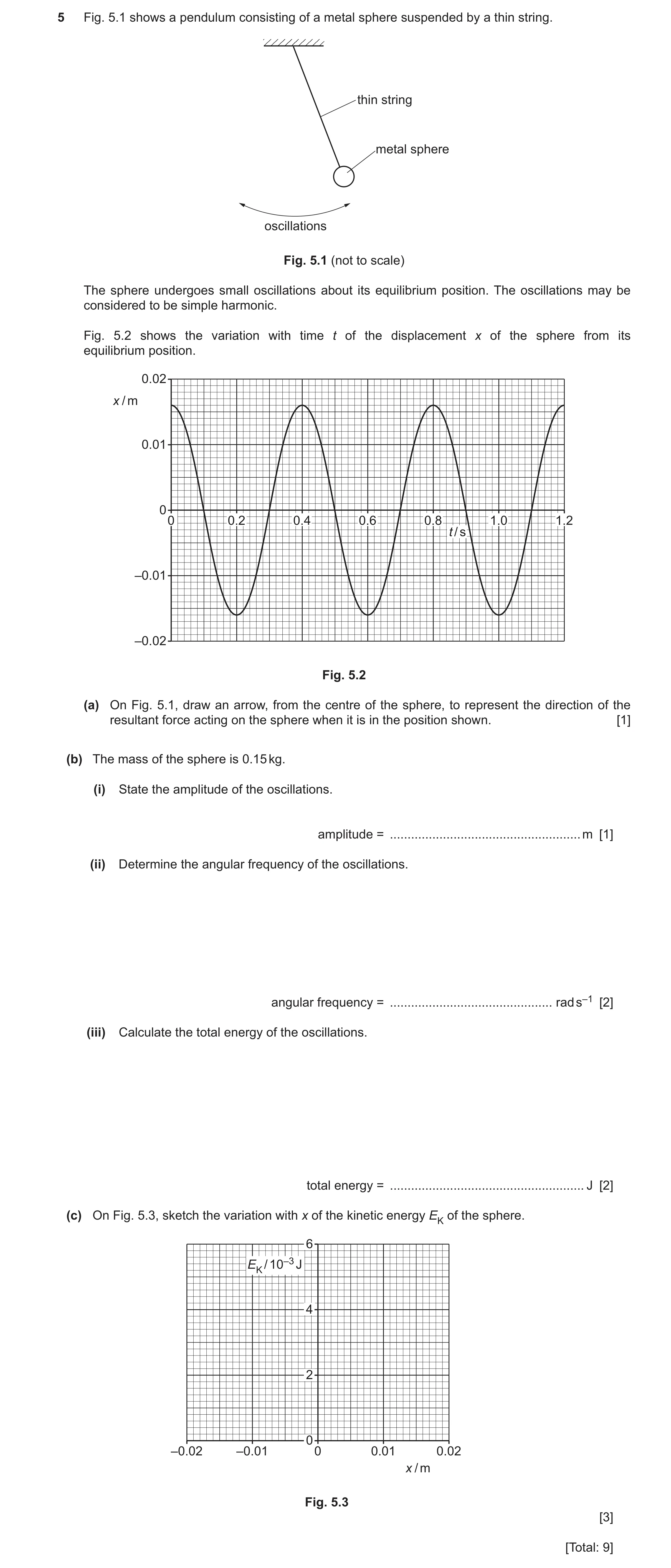
5 Fig. 5.1 shows a pendulum consisting of a metal sphere suspended by a thin string. thin string metal sphere oscillations Fig. 5.1 (not to scale) The sphere undergoes small oscillations about its equilibrium position. The oscillations may be considered to be simple harmonic. Fig. 5.2 shows the variation with time t of the displacement x of the sphere from its equilibrium position. 0.02 x / m 0.01 0 0 0.2 0.4 0.6 0.8 1.0 1.2 t / s –0.01 –0.02 Fig. 5.2 (a) On Fig. 5.1, draw an arrow, from the centre of the sphere, to represent the direction of the resultant force acting on the sphere when it is in the position shown. [1] (b) The mass of the sphere is 0.15 kg. (i) State the amplitude of the oscillations. amplitude = … m [1] (ii) Determine the angular frequency of the oscillations. angular frequency = … rad s–1 [2] (iii) Calculate the total energy of the oscillations. total energy = … J [2] (c) On Fig. 5.3, sketch the variation with x of the kinetic energy EK of the sphere. 6 EK / 10–3 J 4 2 0 –0.02 –0.01 0 0.01 0.02 x / m Fig. 5.3 [3] [Total: 9]
9 marks
Mark scheme: 5(a) arrow from sphere, perpendicular to string, pointing left and down B1 5(b)(i) amplitude = 0.016 m A1 5(b)(ii) angular frequency = 2 / T C1 = 2 / 0.40 A1 = 16 rad s–1 5(b)(iii) total energy = ½m2x02 C1 = ½ 0.15 15.72 0.0162 A1 = 4.7 10–3 J 5(c) dome-shaped curve starting and ending on the x-axis, with peak at x = 0 B1 maximum EK shown as 4.7 10–3 J B1 minimum x shown as –0.016 m and maximum x shown as +0.016 m at the ends of the line B1
This question in 9702/42 Oct/Nov 2024
Q14 · A small crystal is made to vibrate with simple harmonic motion 9702/42 Feb/March 2025
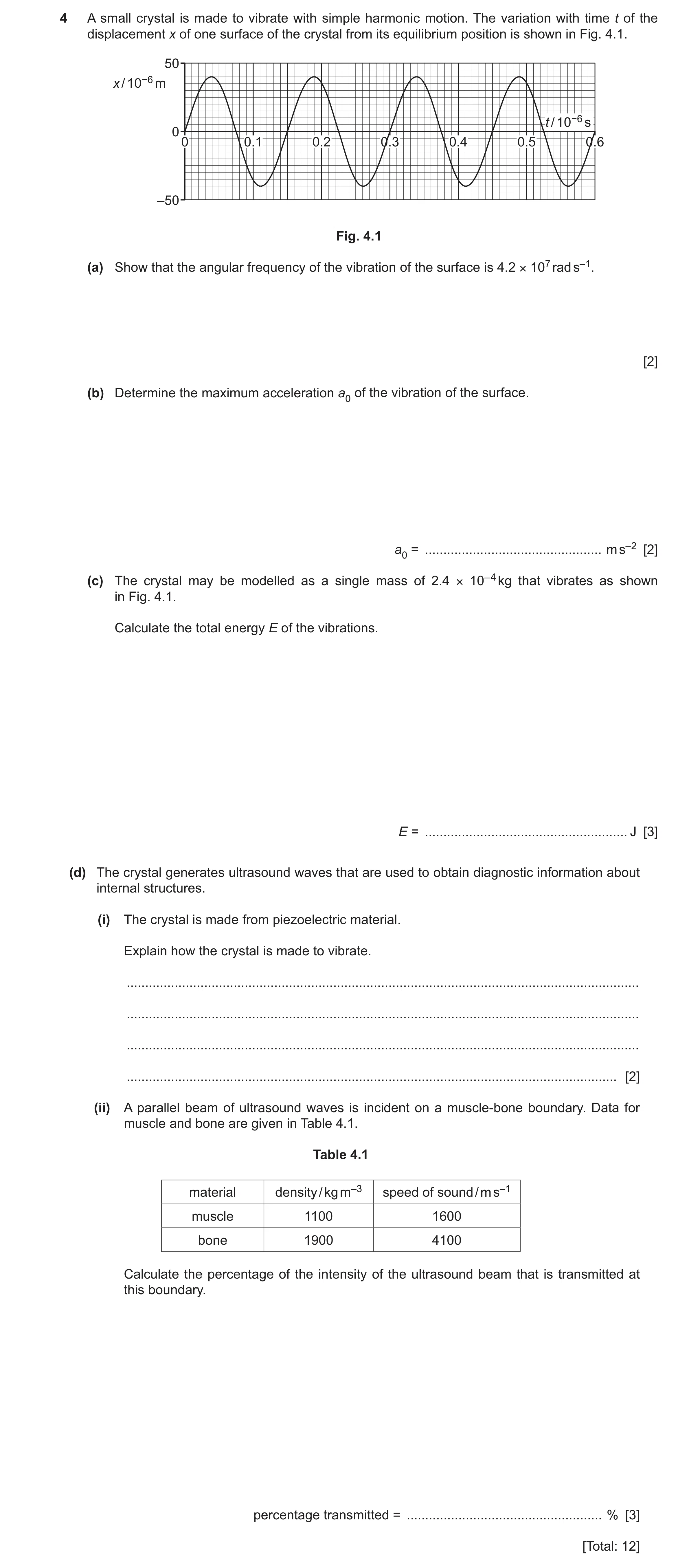
4 A small crystal is made to vibrate with simple harmonic motion. The variation with time t of the displacement x of one surface of the crystal from its equilibrium position is shown in Fig. 4.1. 50 x / 10−6 m t / 10−6 s 0 0 0.1 0.2 0.3 0.4 0.5 0.6 –50 Fig. 4.1 (a) Show that the angular frequency of the vibration of the surface is 4.2 × 10⁷ rad s–1. [2] (b) Determine the maximum acceleration a0 of the vibration of the surface. a0 = … m s–2 [2] (c) The crystal may be modelled as a single mass of 2.4 × 10– 4 kg that vibrates as shown in Fig. 4.1. Calculate the total energy E of the vibrations. E = … J [3] (d) The crystal generates ultrasound waves that are used to obtain diagnostic information about internal structures. (i) The crystal is made from piezoelectric material. Explain how the crystal is made to vibrate. … … … … [2] (ii) A parallel beam of ultrasound waves is incident on a muscle‑bone boundary. Data for muscle and bone are given in Table 4.1. Table 4.1 material density / kg m–3 speed of sound / m s–1 muscle 1100 1600 bone 1900 4100 Calculate the percentage of the intensity of the ultrasound beam that is transmitted at this boundary. percentage transmitted = … % [3] [Total: 12]
12 marks
Mark scheme: 4(a) = 2 / T C1 = 2 / (0.15 10–6) = 4.2 107 rad s–1 A1 4(b) a0 = 2x0 C1 = (4.2 107)2 40 10–6 A1 = 7.1 1010 m s–2 4(c) E = ½m2xo2 C1 = ½ 2.4 10–4 (4.2 107)2 (40 10–6)2 C1 = 340 J A1 4(d)(i) apply alternating p.d. (to / across crystal) B1 applying p.d. to / across crystal causes it to distort B1 4(d)(ii) Z = c C1 Zm = 1100 1600 (= 1.76 106) Zb = 1900 4100 (= 7.79 106) intensity reflection co-efficient= [(7.79 – 1.76) / (7.79 + 1.76)]2 C1 = 0.40 or 40% percentage transmitted = 60% A1
This question in 9702/42 Feb/March 2025
Q15 · A cuboidal block floats in a liquid with its base horizontal, as shown in Fig 9702/41 May/June 2025
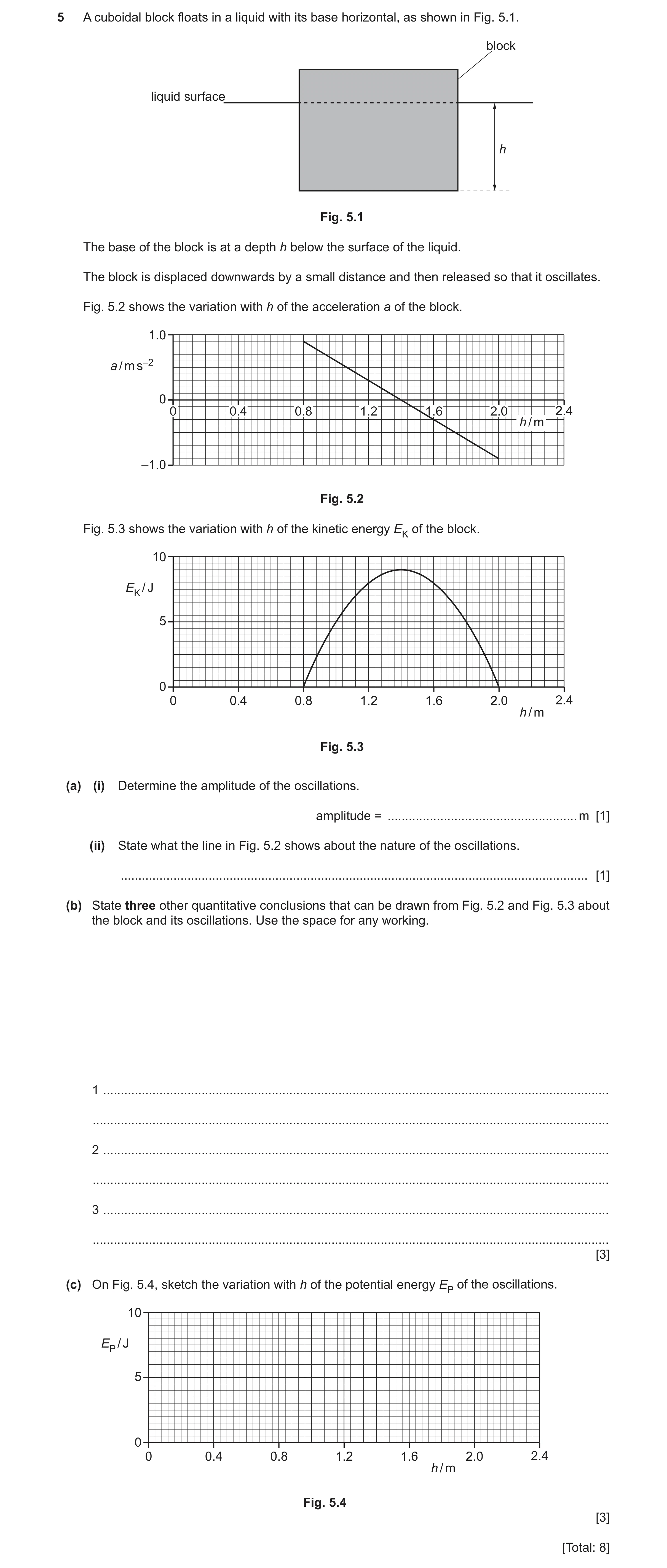
5 A cuboidal block floats in a liquid with its base horizontal, as shown in Fig. 5.1. block liquid surface h Fig. 5.1 The base of the block is at a depth h below the surface of the liquid. The block is displaced downwards by a small distance and then released so that it oscillates. Fig. 5.2 shows the variation with h of the acceleration a of the block. 1.0 a / m s–2 0 0 0.4 0.8 1.2 1.6 2.0 2.4 h / m –1.0 Fig. 5.2 Fig. 5.3 shows the variation with h of the kinetic energy EK of the block. 10 EK / J 5 0 0 0.4 0.8 1.2 1.6 2.0 2.4 h / m Fig. 5.3 (a) (i) Determine the amplitude of the oscillations. amplitude = … m [1] (ii) State what the line in Fig. 5.2 shows about the nature of the oscillations. … [1] (b) State three other quantitative conclusions that can be drawn from Fig. 5.2 and Fig. 5.3 about the block and its oscillations. Use the space for any working. 1 … … 2 … … 3 … … [3] (c) On Fig. 5.4, sketch the variation with h of the potential energy EP of the oscillations. 10 EP / J 5 0 0 0.4 0.8 1.2 1.6 2.0 2.4 h / m Fig. 5.4 [3] [Total: 8]
8 marks
Mark scheme: 5(a)(i) amplitude = 0.60 m A1 5(a)(ii) oscillations are simple harmonic B1 5(b) Any three points from: B3 • mean / equilibrium position is at h = 1.4 m • total energy of oscillations = 9.0 J • angular frequency of oscillations = 1.2 rad s–1 or period of oscillations = 5.1 s or frequency of oscillation = 0.19 Hz • maximum speed of block = 0.73 m s–1 • mass of block = 33 kg 5(c) U-shaped curve resting on h axis (with minimum at EP = 0) B1 curve from h = 0.8 m to h = 2.0 m, with minimum EP shown at h = 1.4 m B1 both end-points of curve shown at EP = 9.0 J B1
This question in 9702/41 May/June 2025
Q16 · A cuboidal block floats in a liquid with its base horizontal, as shown in Fig 9702/43 May/June 2025
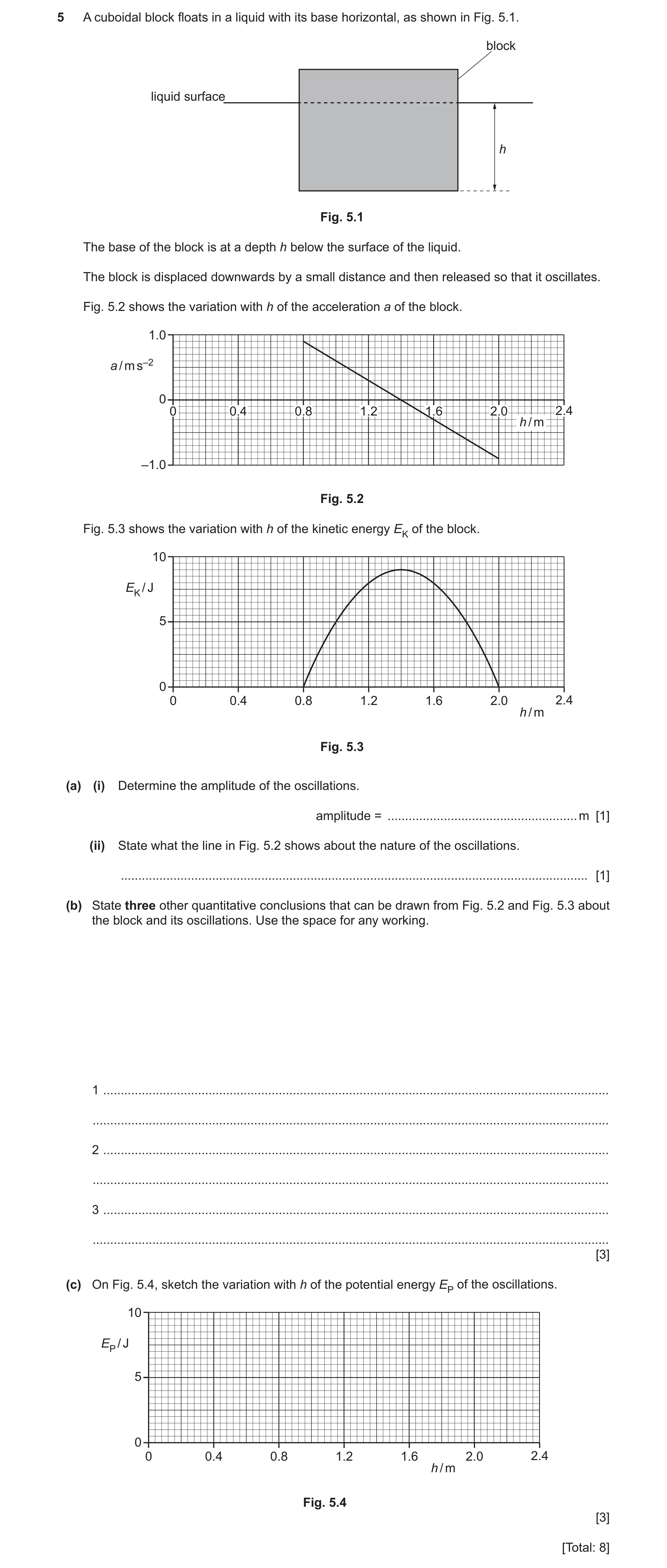
5 A cuboidal block floats in a liquid with its base horizontal, as shown in Fig. 5.1. block liquid surface h Fig. 5.1 The base of the block is at a depth h below the surface of the liquid. The block is displaced downwards by a small distance and then released so that it oscillates. Fig. 5.2 shows the variation with h of the acceleration a of the block. 1.0 a / m s–2 0 0 0.4 0.8 1.2 1.6 2.0 2.4 h / m –1.0 Fig. 5.2 Fig. 5.3 shows the variation with h of the kinetic energy EK of the block. 10 EK / J 5 0 0 0.4 0.8 1.2 1.6 2.0 2.4 h / m Fig. 5.3 (a) (i) Determine the amplitude of the oscillations. amplitude = … m [1] (ii) State what the line in Fig. 5.2 shows about the nature of the oscillations. … [1] (b) State three other quantitative conclusions that can be drawn from Fig. 5.2 and Fig. 5.3 about the block and its oscillations. Use the space for any working. 1 … … 2 … … 3 … … [3] (c) On Fig. 5.4, sketch the variation with h of the potential energy EP of the oscillations. 10 EP / J 5 0 0 0.4 0.8 1.2 1.6 2.0 2.4 h / m Fig. 5.4 [3] [Total: 8]
8 marks
Mark scheme: 5(a)(i) amplitude = 0.60 m A1 5(a)(ii) oscillations are simple harmonic B1 5(b) Any three points from: B3 • mean / equilibrium position is at h = 1.4 m • total energy of oscillations = 9.0 J • angular frequency of oscillations = 1.2 rad s–1 or period of oscillations = 5.1 s or frequency of oscillation = 0.19 Hz • maximum speed of block = 0.73 m s–1 • mass of block = 33 kg 5(c) U-shaped curve resting on h axis (with minimum at EP = 0) B1 curve from h = 0.8 m to h = 2.0 m, with minimum EP shown at h = 1.4 m B1 both end-points of curve shown at EP = 9.0 J B1
This question in 9702/43 May/June 2025
 12
12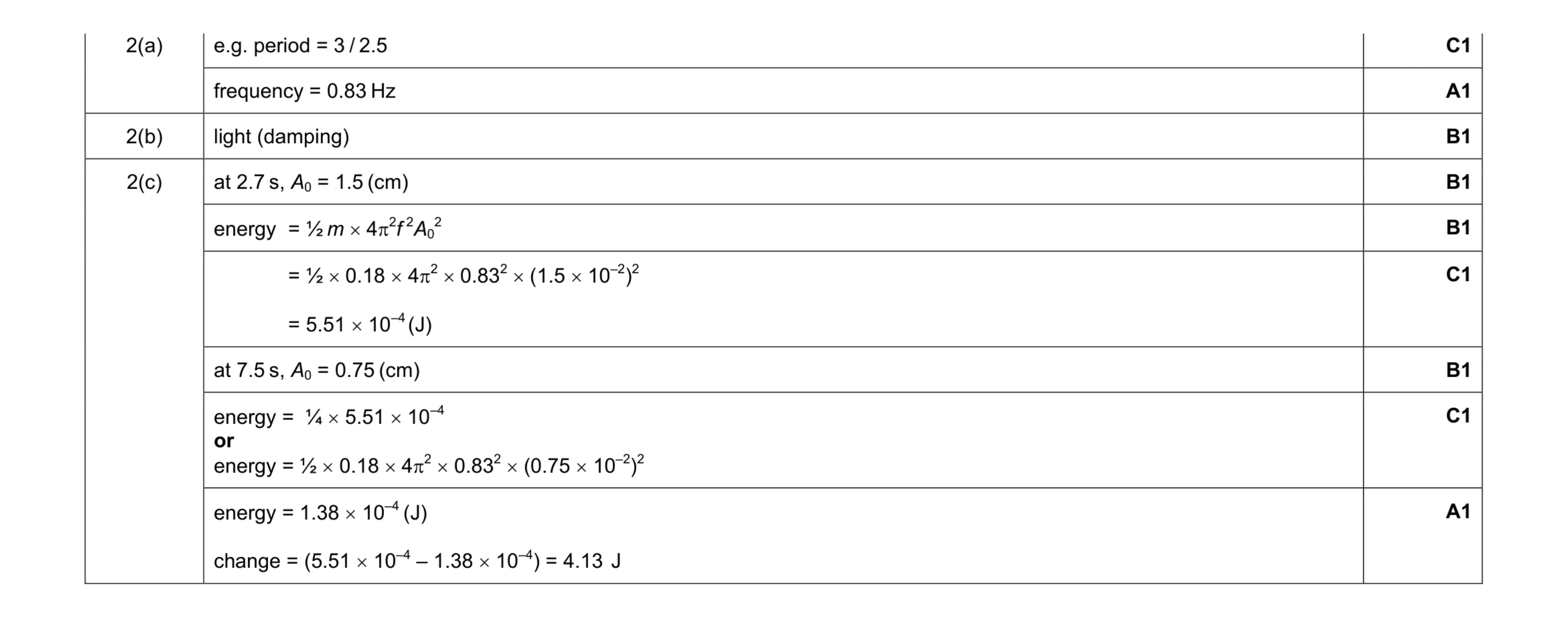 9
9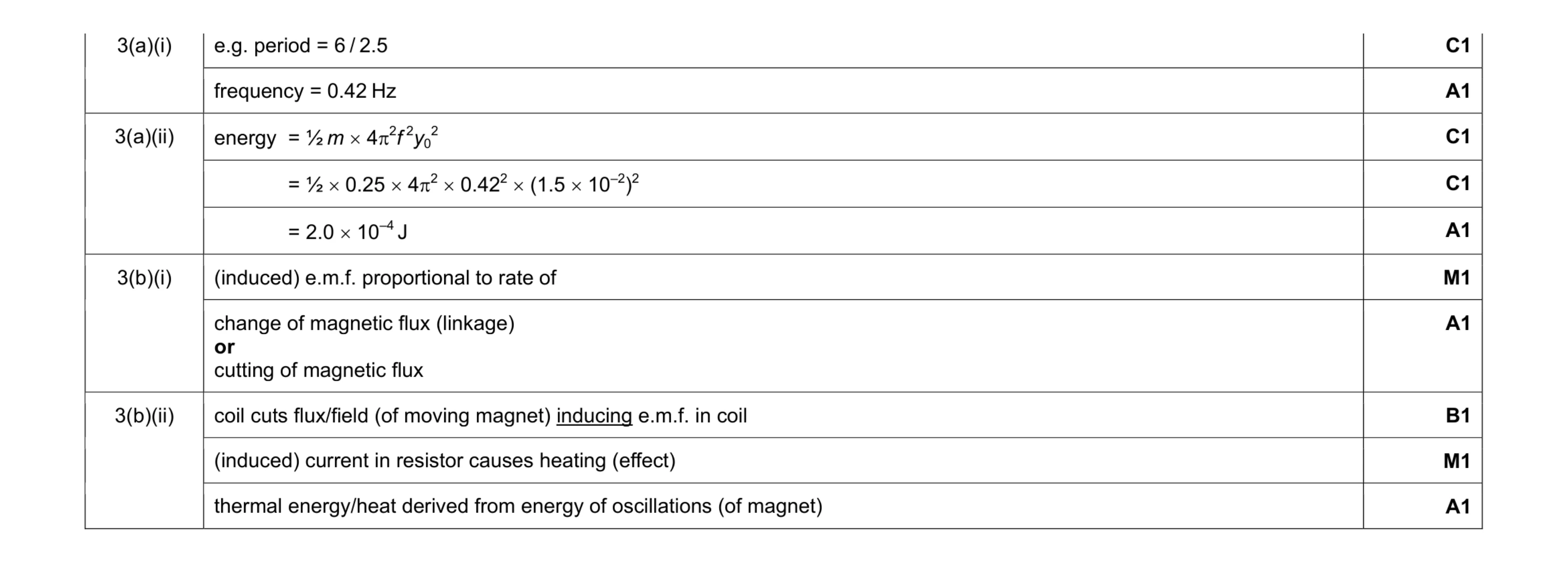 10
10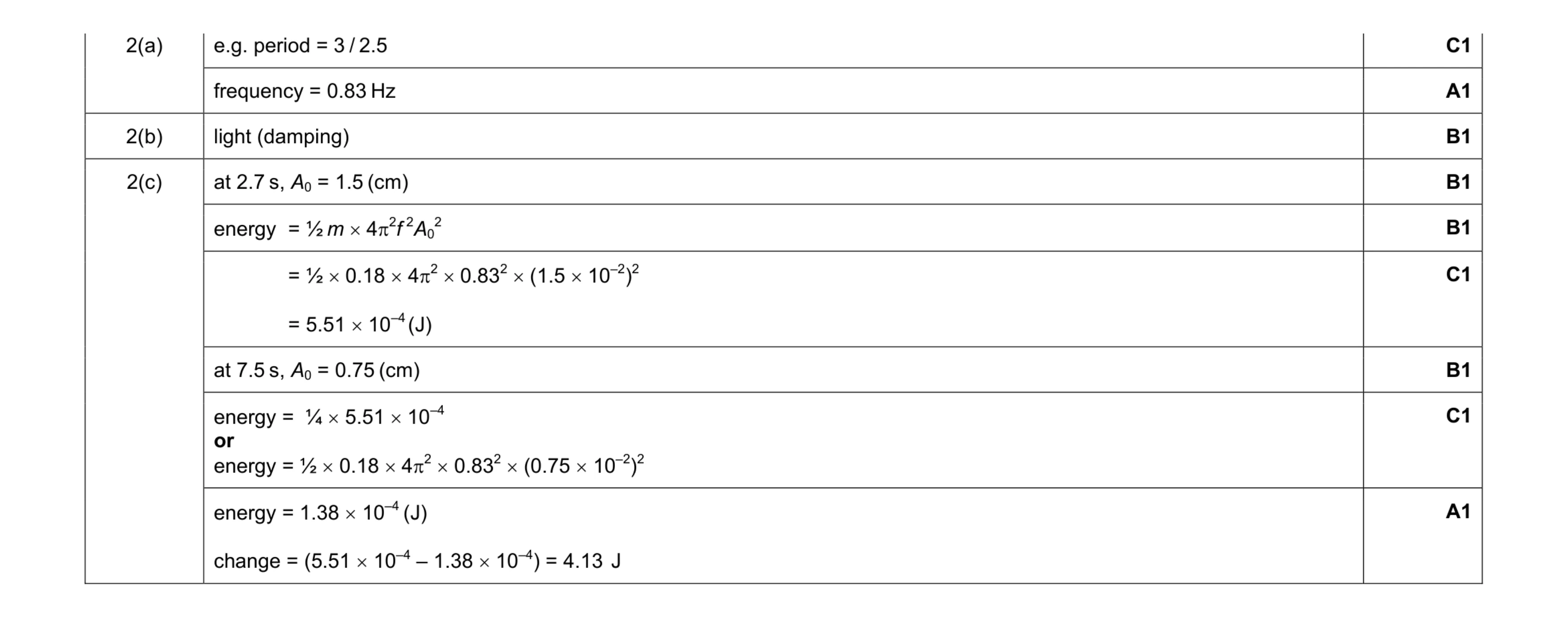 9
9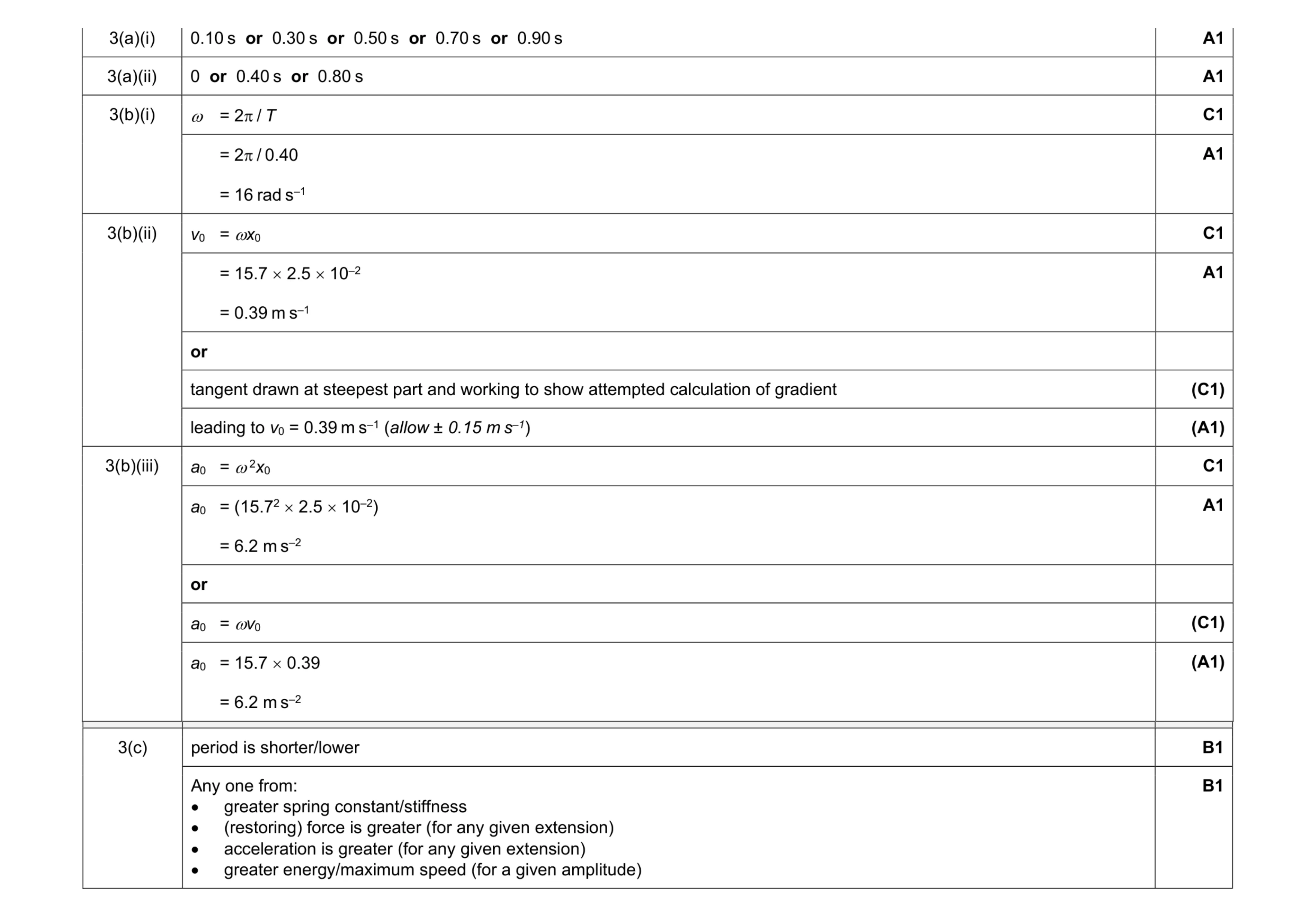 10
10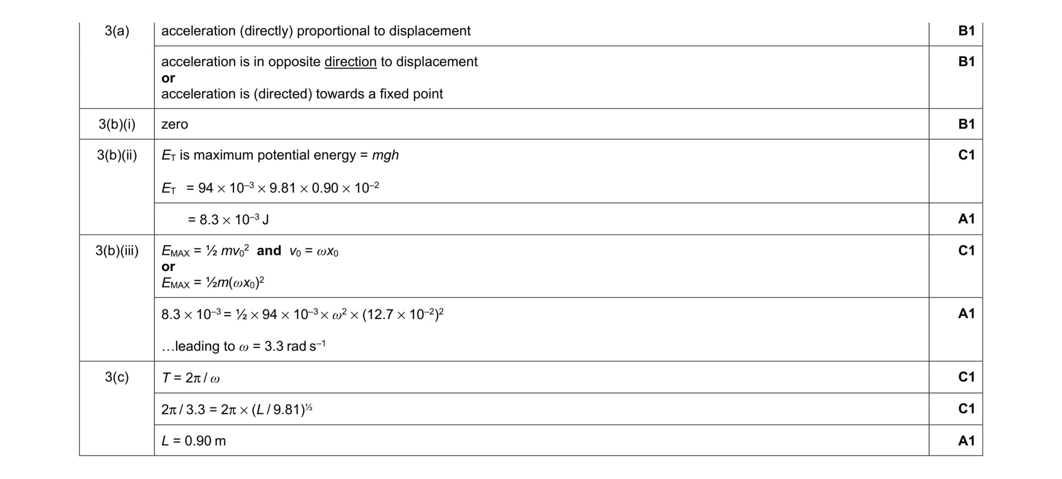 10
10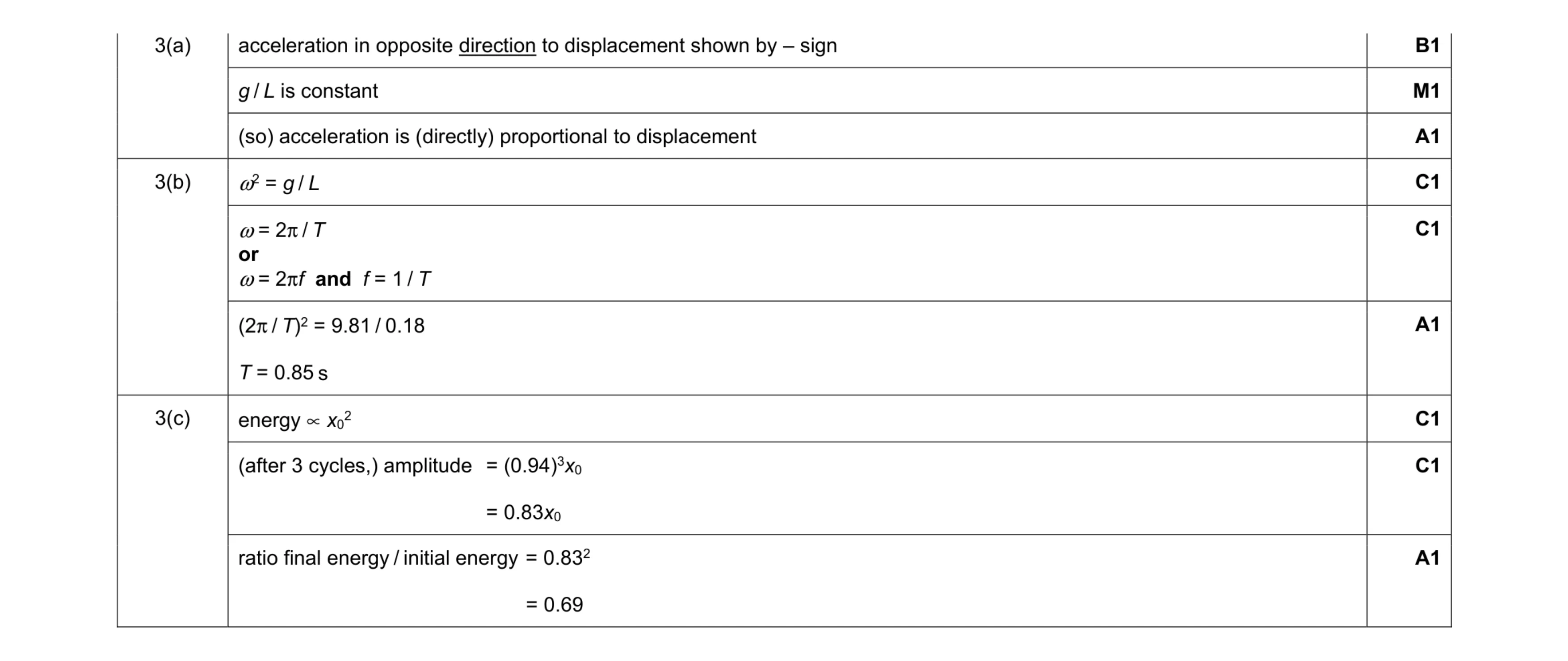 9
9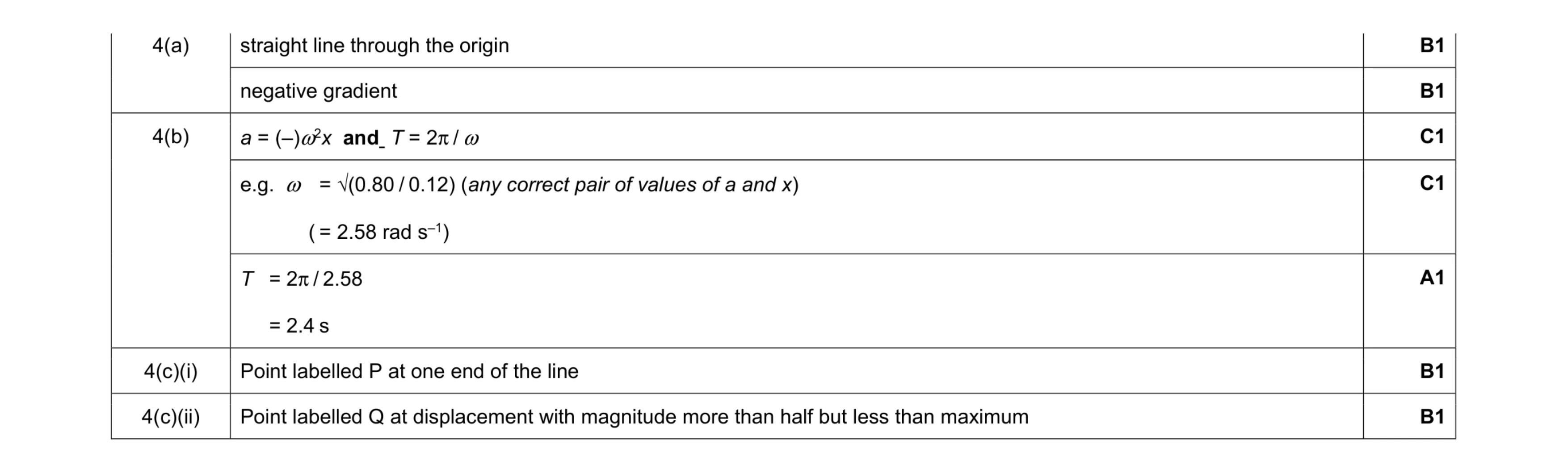 7
7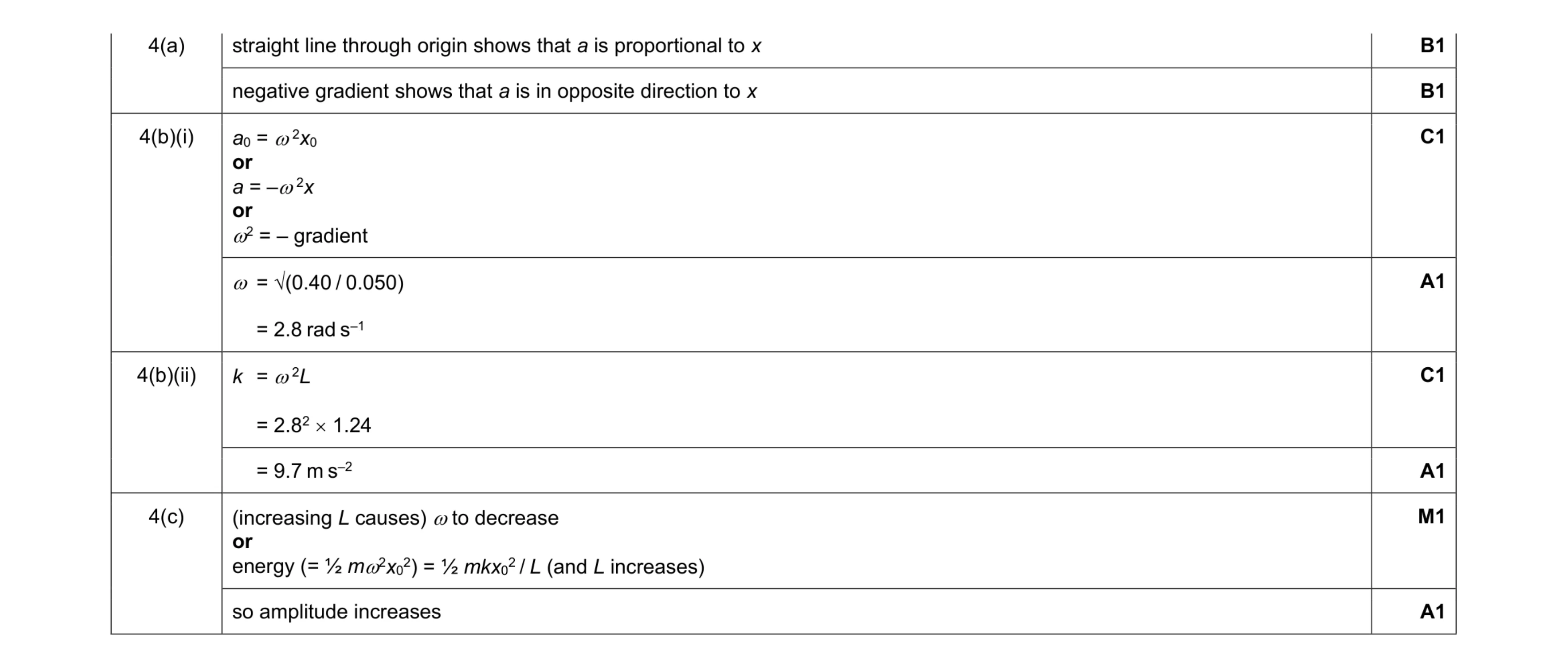 8
8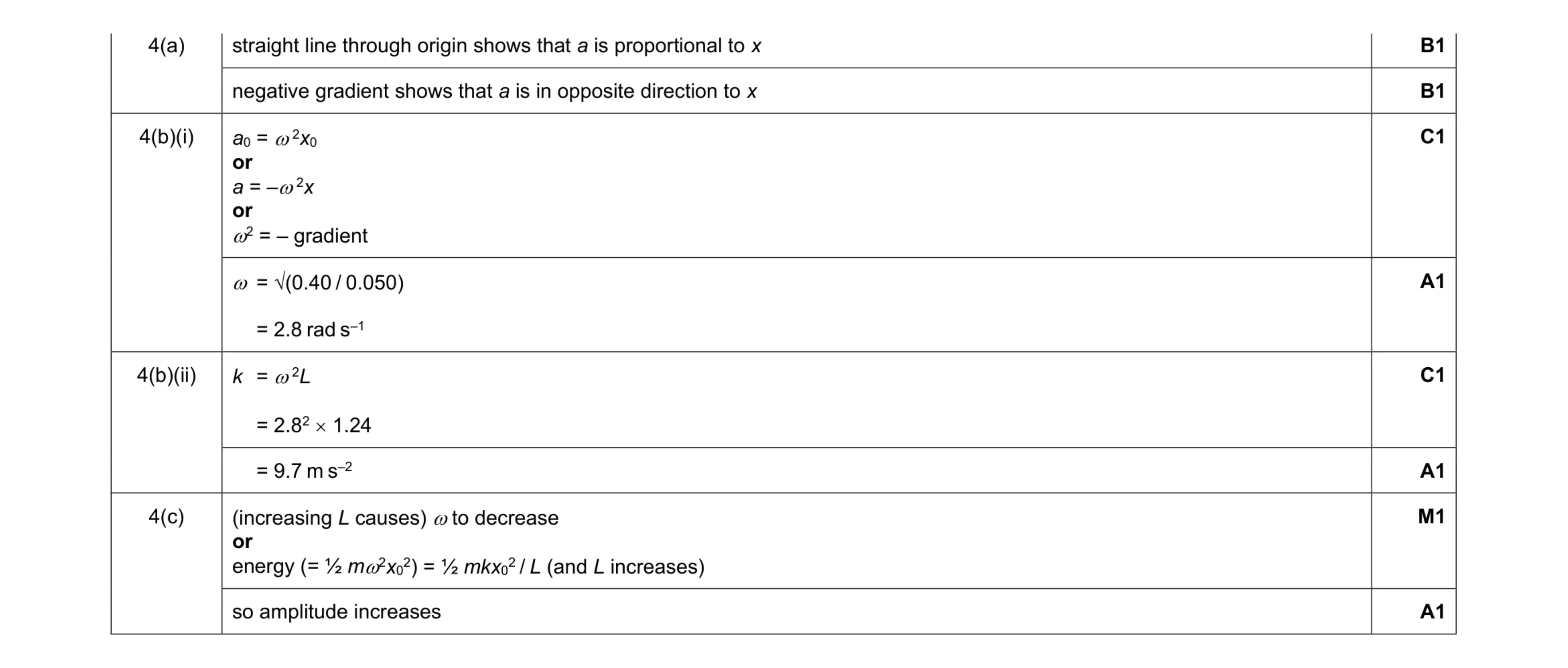 8
8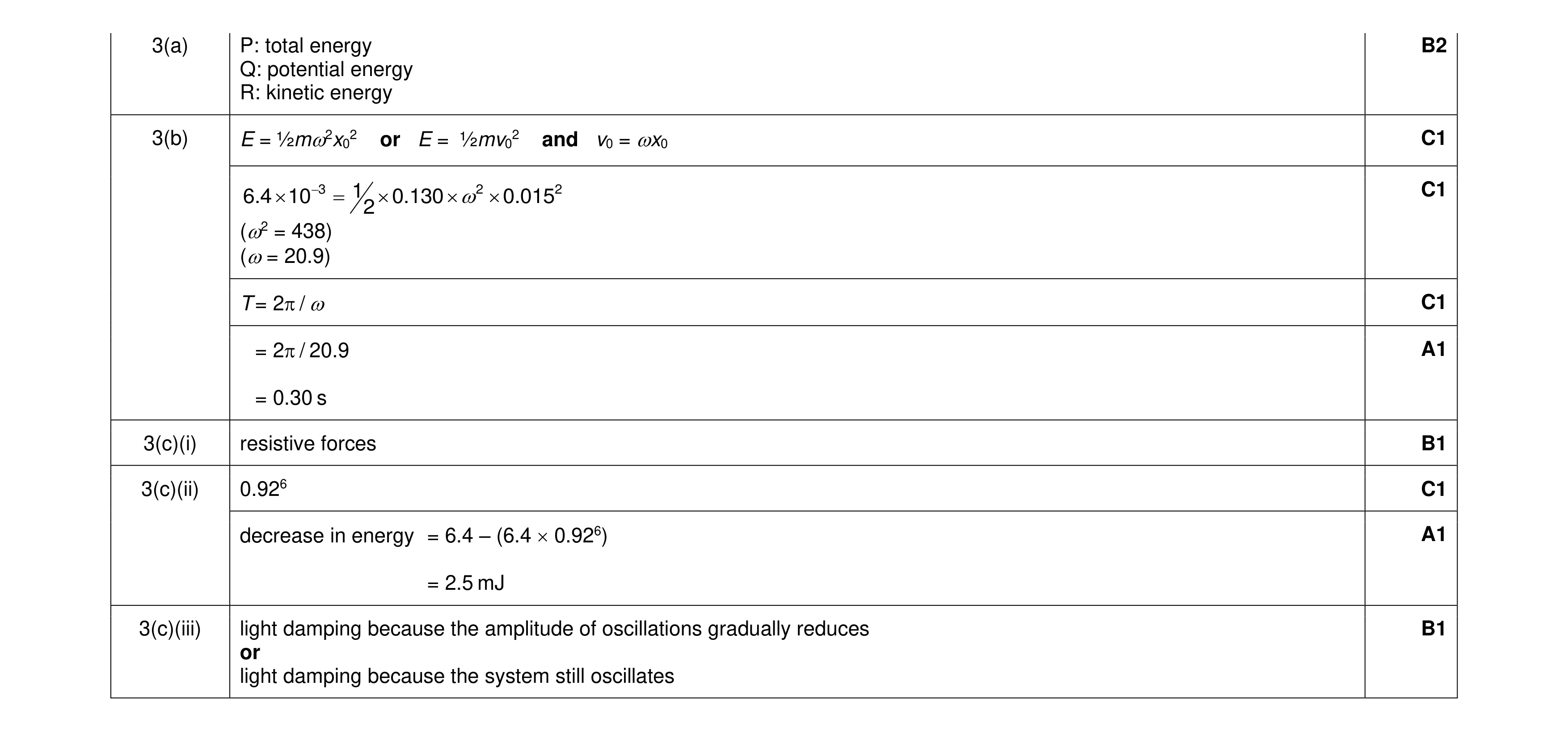 10
10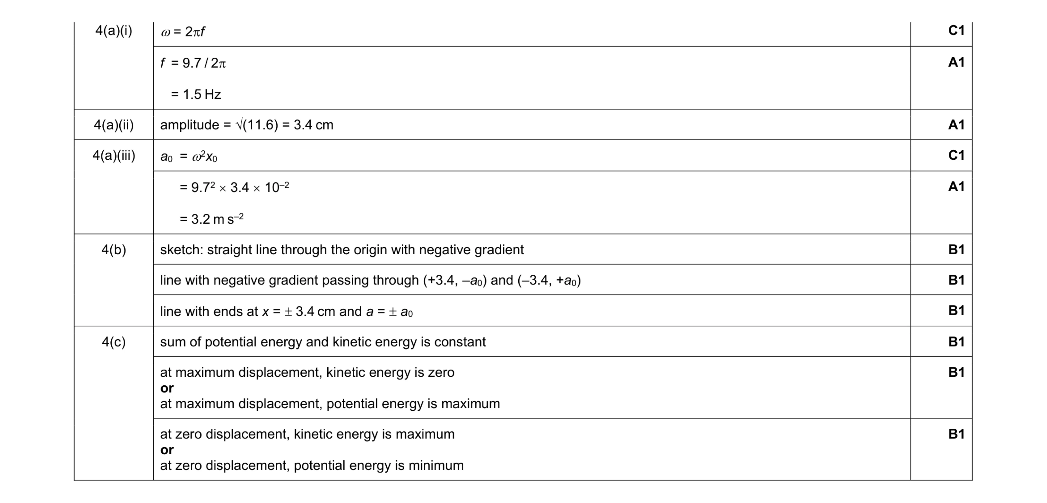 11
11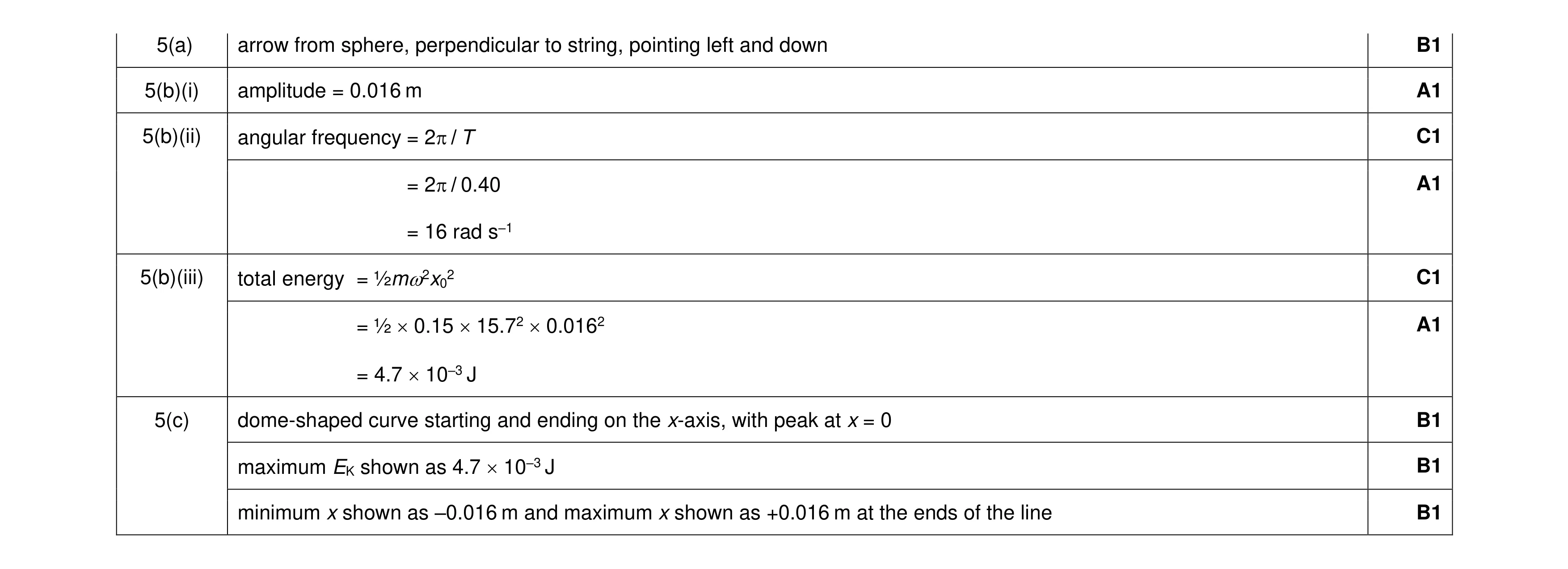 9
9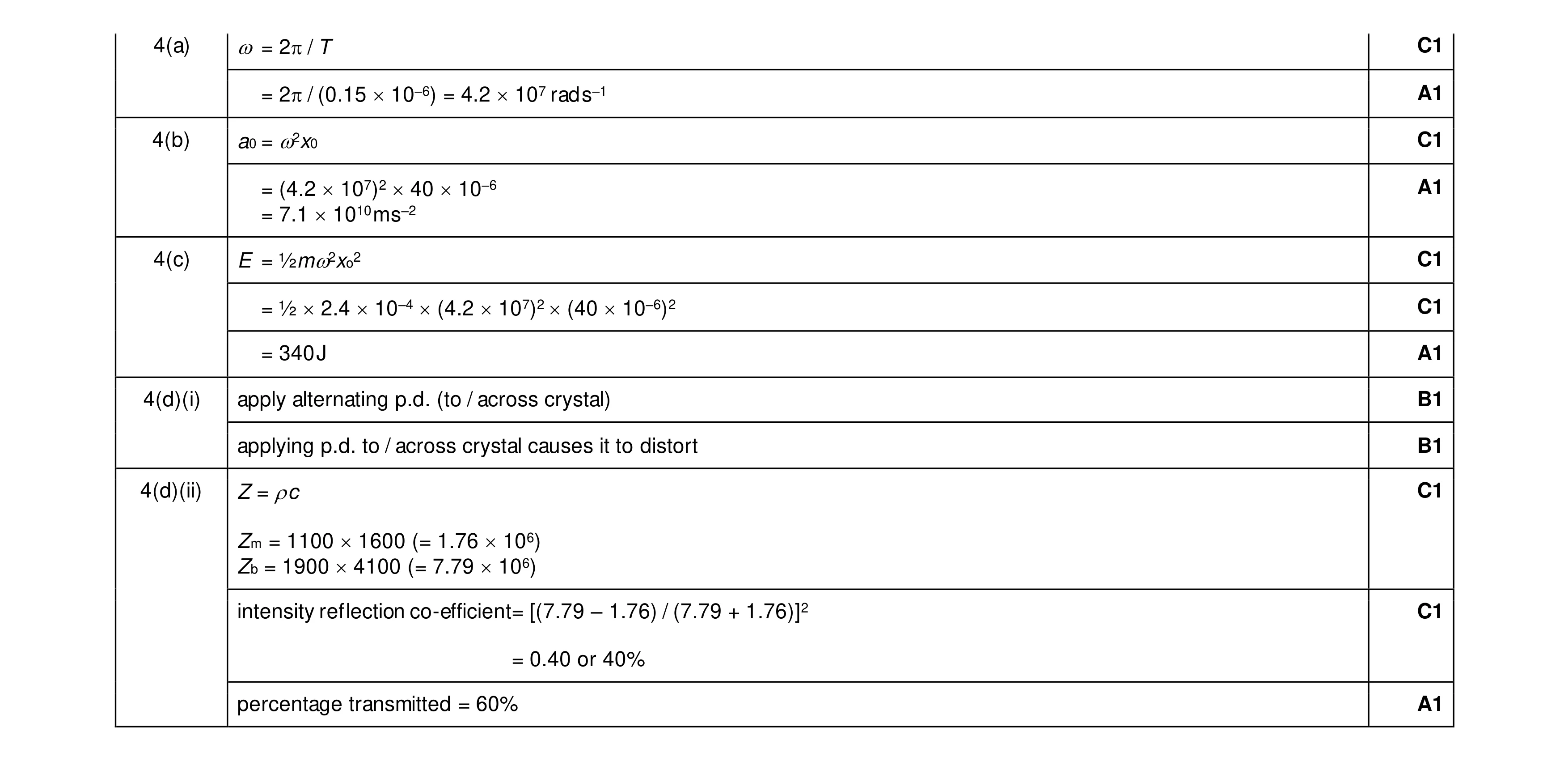 12
12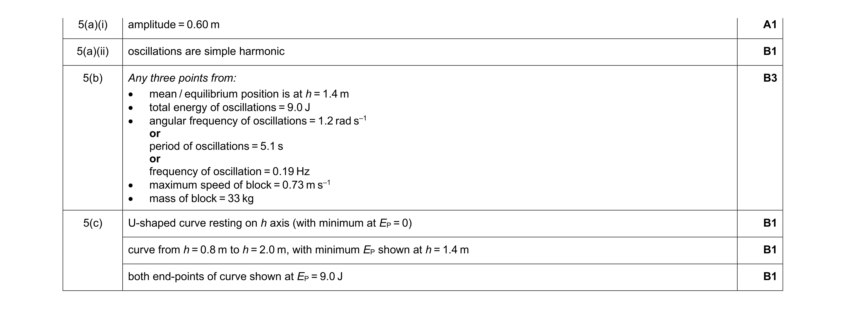 8
8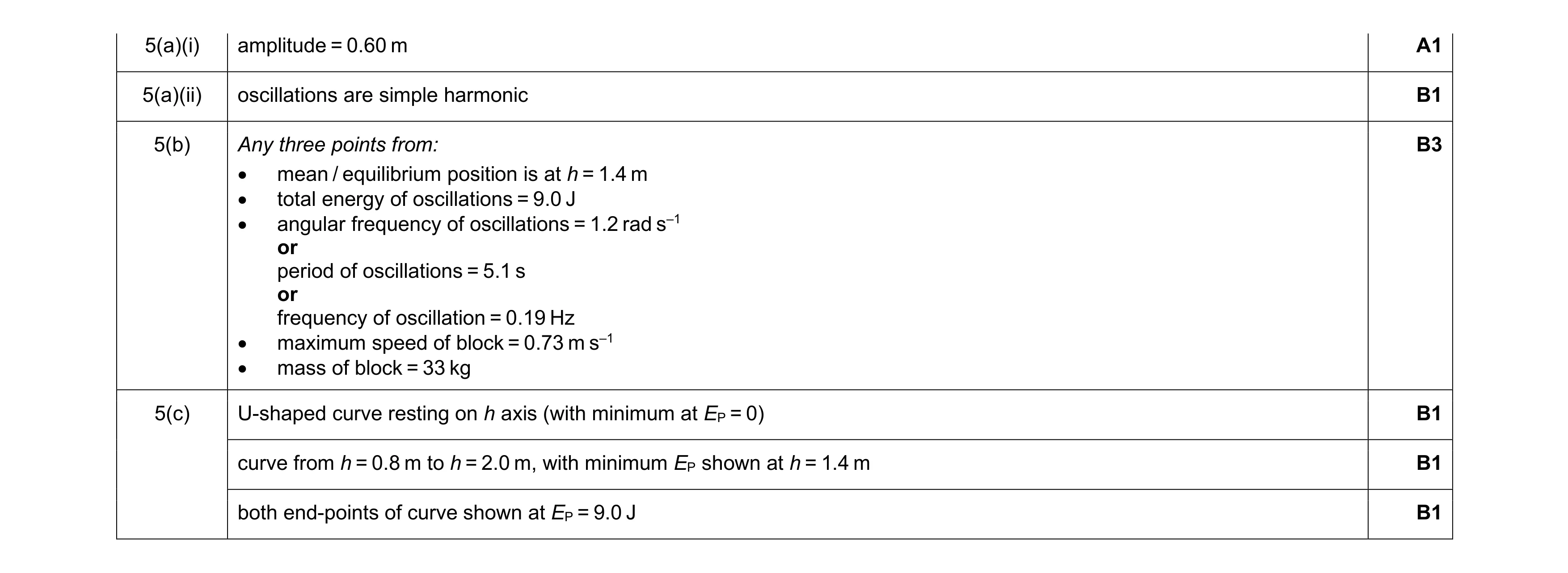 8
8