Cambridge IGCSE Physics 0625 — 2017 May/June Paper 4 · Variant 2
0625/42/M/J/17 · 10 questions · 80 marks · ≈90 min
The question paper and its mark scheme, free to read here and free to download. This is Cambridge’s own paper, exactly as it was sat.
Question paper20 pages
Mark scheme10 pages
Answers below. Sit the paper first if you are practising.
Questions as text
Q1 · Speed is a scalar quantity and velocity is a vector quantity
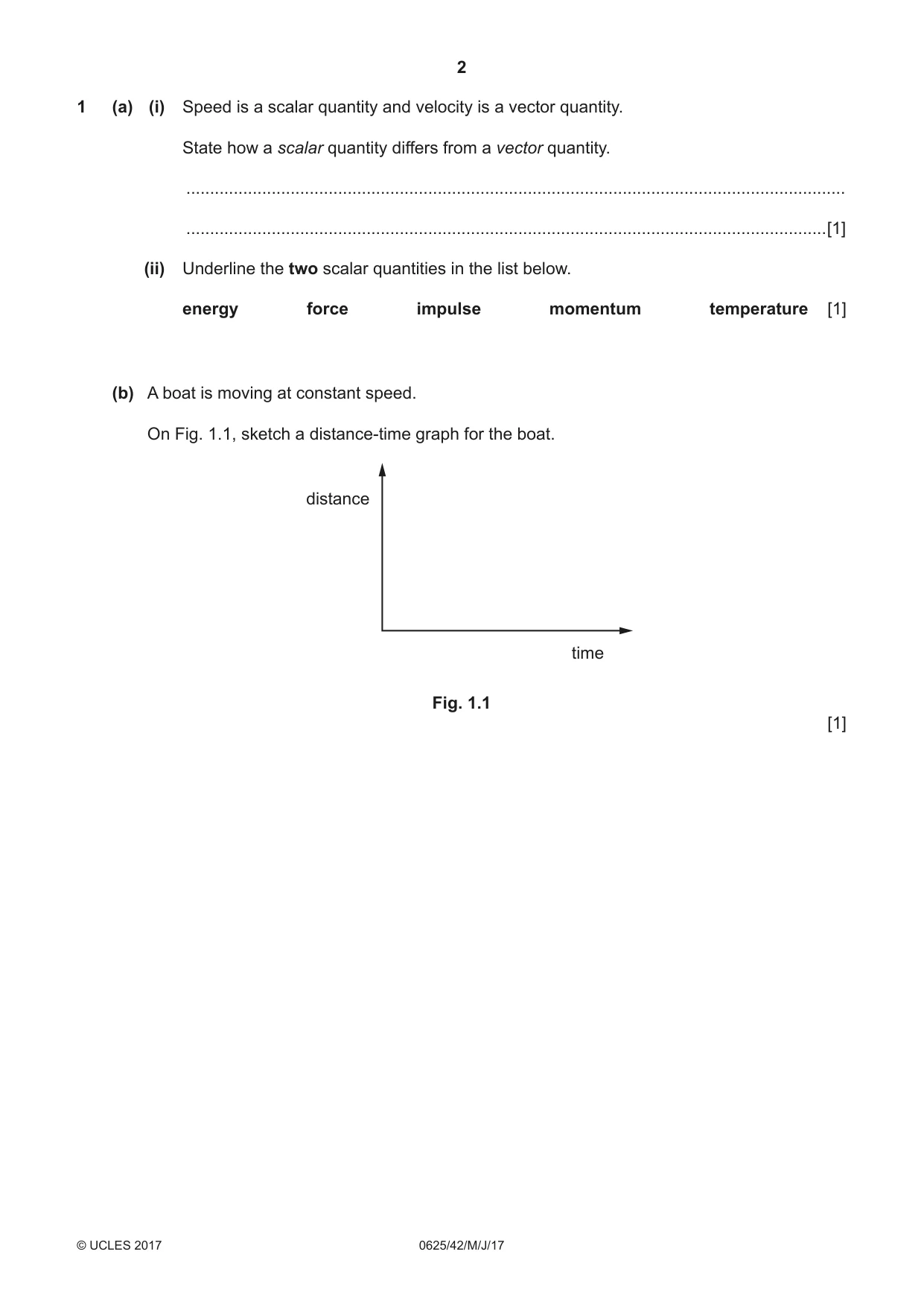
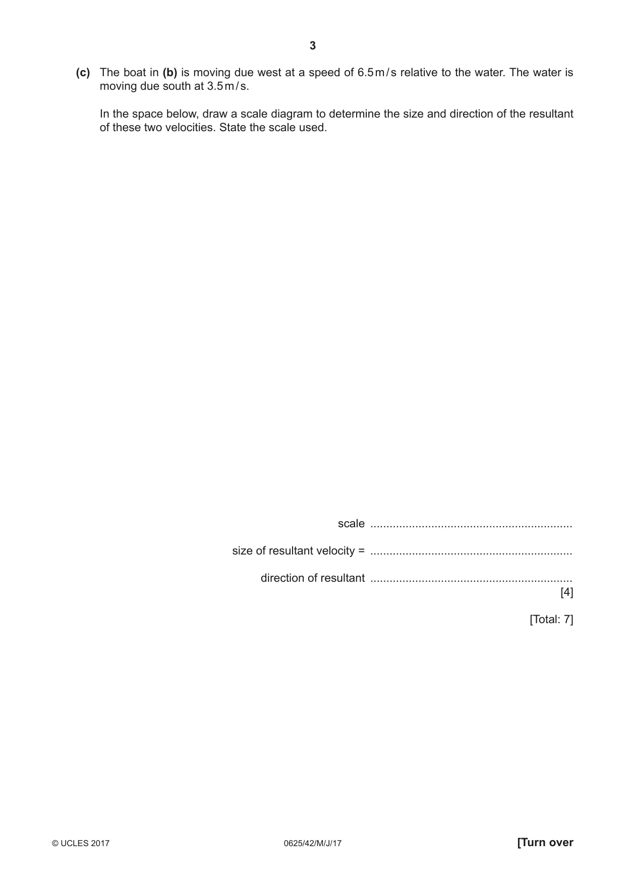
1 (a) (i) Speed is a scalar quantity and velocity is a vector quantity. State how a scalar quantity differs from a vector quantity. ........................................................................................................................................... .......................................................................................................................................[1] (ii) Underline the two scalar quantities in the list below. energy force impulse momentum temperature [1] (b) A boat is moving at constant speed. On Fig. 1.1, sketch a distance-time graph for the boat. distance time Fig. 1.1 [1] (c) The boat in (b) is moving due west at a speed of 6.5 m / s relative to the water. The water is moving due south at 3.5 m / s. In the space below, draw a scale diagram to determine the size and direction of the resultant of these two velocities. State the scale used. scale ............................................................... size of resultant velocity = ............................................................... direction of resultant ............................................................... [4] [Total: 7]
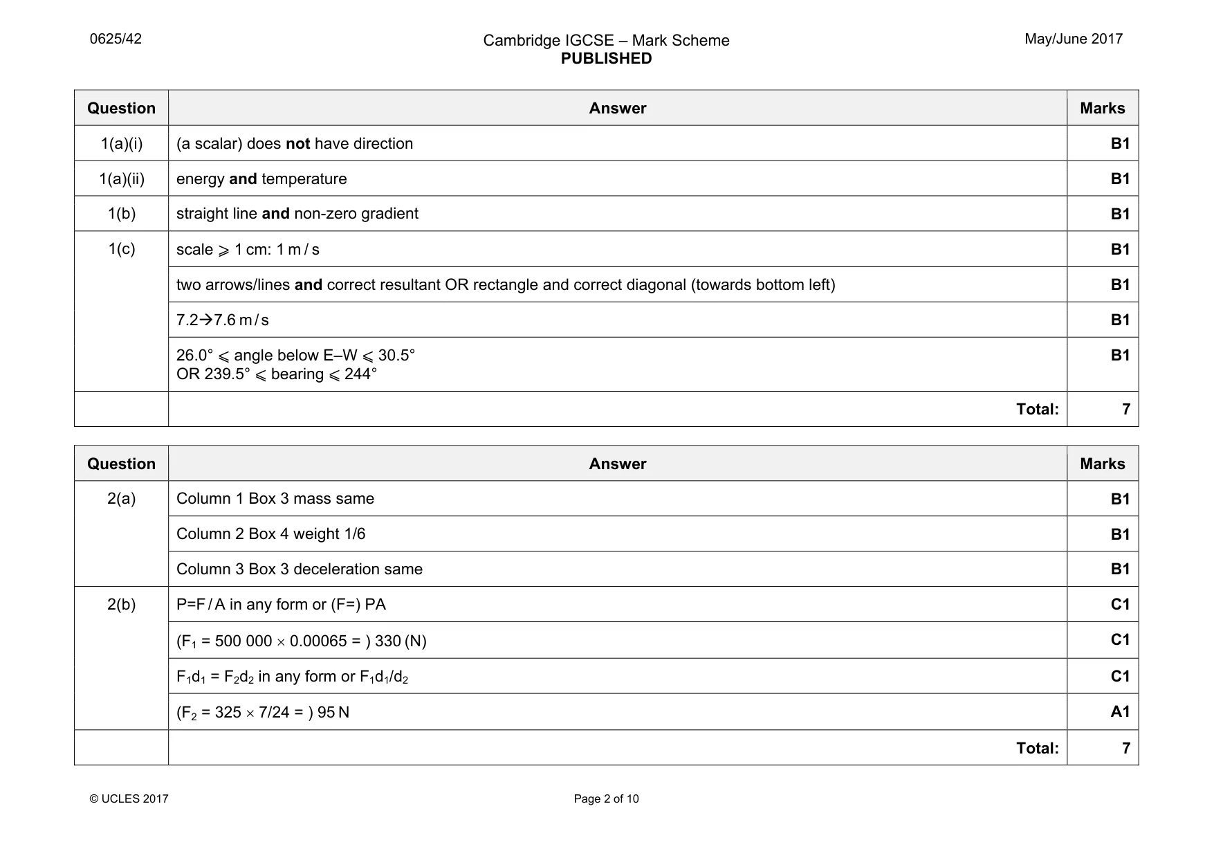
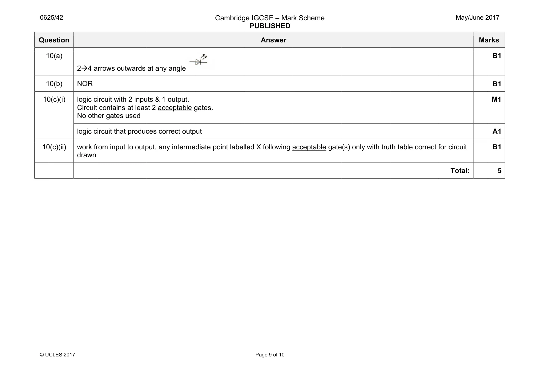
Mark scheme: 1(a)(i) (a scalar) does not have direction B1 1(a)(ii) energy and temperature B1 1(b) straight line and non-zero gradient B1 1(c) scale ⩾ 1 cm: 1 m / s B1 two arrows/lines and correct resultant OR rectangle and correct diagonal (towards bottom left) B1 7.2Æ7.6 m / s B1 26.0° ⩽ angle below E–W ⩽ 30.5° OR 239.5° ⩽ bearing ⩽ 244° B1 Total: 7
Q2 · A vehicle designed to be used on the Moon
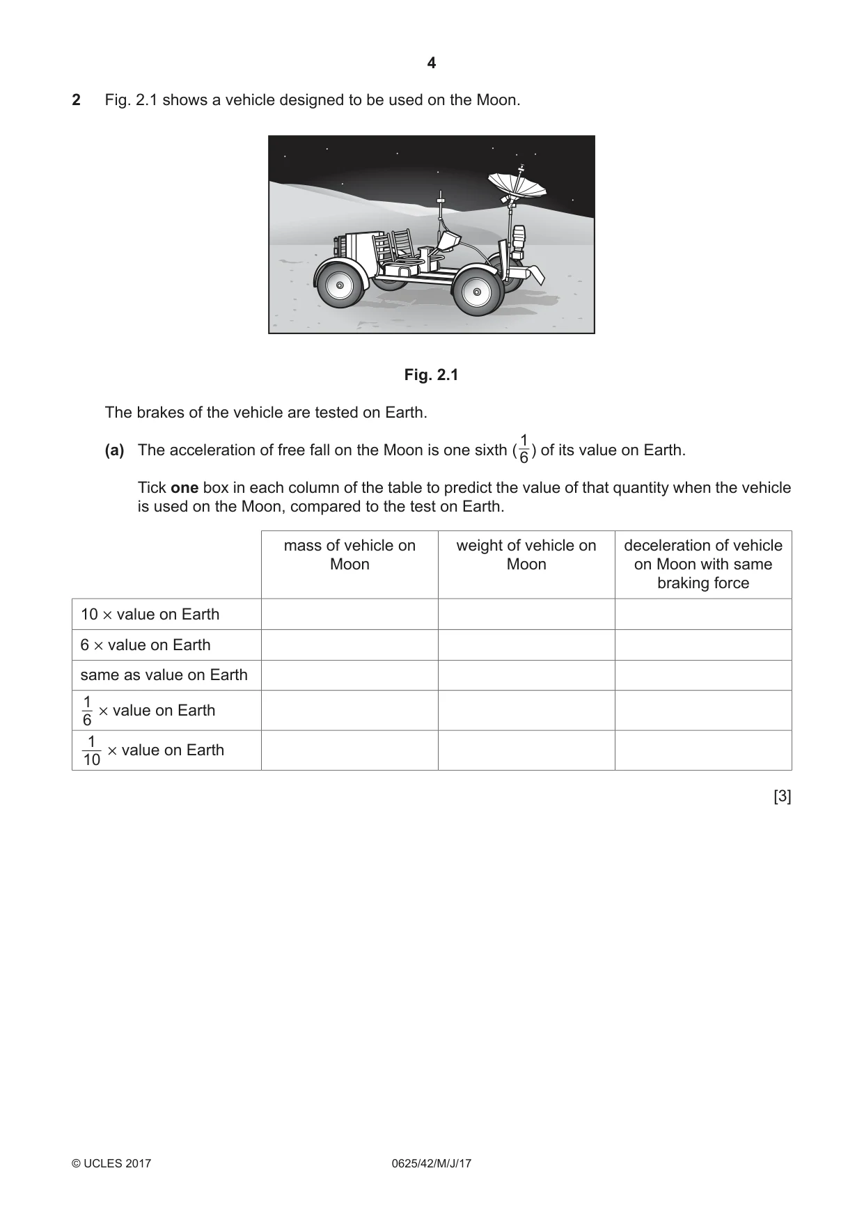
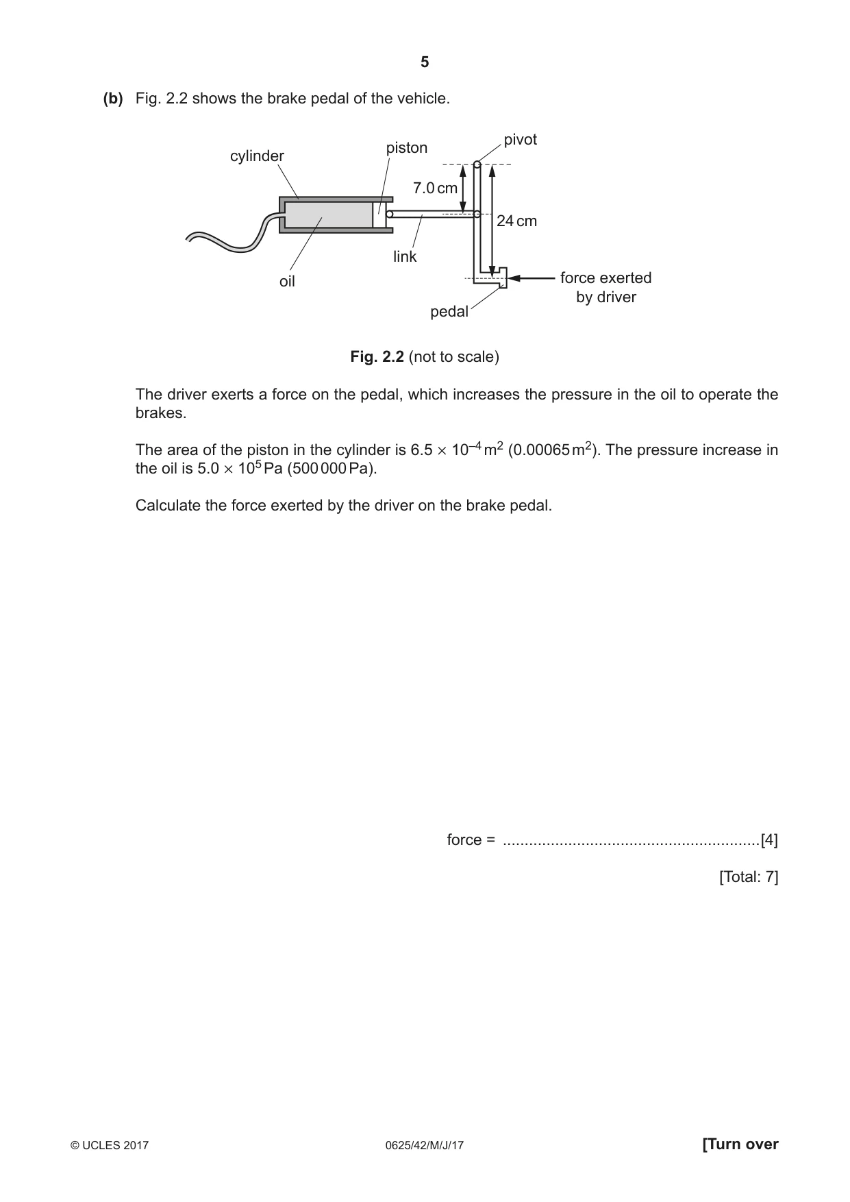
2 Fig. 2.1 shows a vehicle designed to be used on the Moon. Fig. 2.1 The brakes of the vehicle are tested on Earth. 1 (a) The acceleration of free fall on the Moon is one sixth ( ) of its value on Earth. 6 Tick one box in each column of the table to predict the value of that quantity when the vehicle is used on the Moon, compared to the test on Earth. mass of vehicle on weight of vehicle on deceleration of vehicle Moon Moon on Moon with same braking force 10 # value on Earth 6 # value on Earth same as value on Earth 1 # value on Earth 6 1 # value on Earth 10 [3] (b) Fig. 2.2 shows the brake pedal of the vehicle. pivot piston cylinder 7.0 cm 24 cm link oil force exerted by driver pedal Fig. 2.2 (not to scale) The driver exerts a force on the pedal, which increases the pressure in the oil to operate the brakes. The area of the piston in the cylinder is 6.5 # 10–4 m2 (0.00065 m2). The pressure increase in the oil is 5.0 # 105 Pa (500 000 Pa). Calculate the force exerted by the driver on the brake pedal. force = ...........................................................[4] [Total: 7]
Mark scheme: 2(a) Column 1 Box 3 mass same B1 Column 2 Box 4 weight 1/6 B1 Column 3 Box 3 deceleration same B1 2(b) P=F / A in any form or (F=) PA C1 (F1 = 500 000 × 0.00065 = ) 330 (N) C1 F1d1 = F2d2 in any form or F1d1/d2 C1 (F2 = 325 × 7/24 = ) 95 N A1 Total: 7
Q3 · Underline the pair of quantities which must be multiplied together to calculate impulse
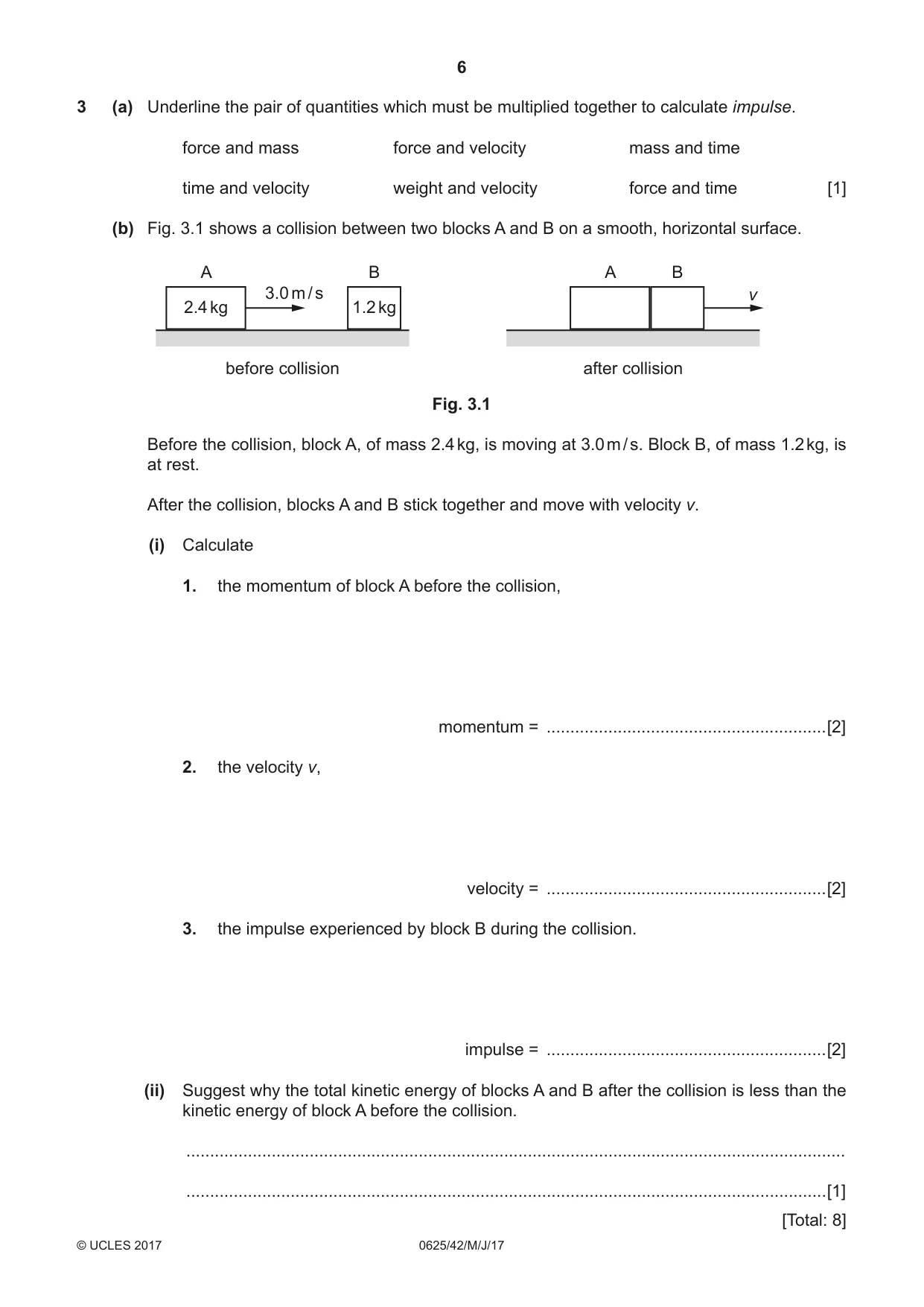
3 (a) Underline the pair of quantities which must be multiplied together to calculate impulse. force and mass force and velocity mass and time time and velocity weight and velocity force and time [1] (b) Fig. 3.1 shows a collision between two blocks A and B on a smooth, horizontal surface. A B A B 3.0 m / s v 2.4 kg 1.2 kg before collision after collision Fig. 3.1 Before the collision, block A, of mass 2.4 kg, is moving at 3.0 m / s. Block B, of mass 1.2 kg, is at rest. After the collision, blocks A and B stick together and move with velocity v. (i) Calculate 1. the momentum of block A before the collision, momentum = ...........................................................[2] 2. the velocity v, velocity = ...........................................................[2] 3. the impulse experienced by block B during the collision. impulse = ...........................................................[2] (ii) Suggest why the total kinetic energy of blocks A and B after the collision is less than the kinetic energy of block A before the collision. ........................................................................................................................................... .......................................................................................................................................[1] [Total: 8]
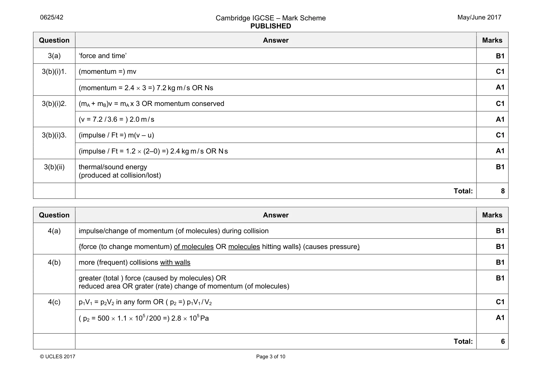
Mark scheme: 3(a) ‘force and time’ B1 3(b)(i)1. (momentum =) mv C1 (momentum = 2.4 × 3 =) 7.2 kg m / s OR Ns A1 3(b)(i)2. (mA + mB)v = mA x 3 OR momentum conserved C1 (v = 7.2 / 3.6 = ) 2.0 m / s A1 3(b)(i)3. (impulse / Ft =) m(v – u) C1 (impulse / Ft = 1.2 × (2–0) =) 2.4 kg m / s OR N s A1 3(b)(ii) thermal/sound energy (produced at collision/lost) B1 Total: 8
Q4 · A balloon contains a fixed mass of gas
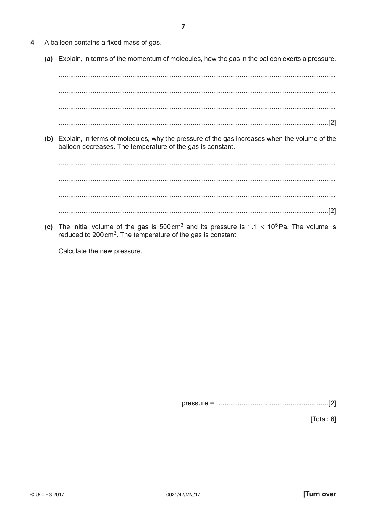
4 A balloon contains a fixed mass of gas. (a) Explain, in terms of the momentum of molecules, how the gas in the balloon exerts a pressure. ................................................................................................................................................... ................................................................................................................................................... ................................................................................................................................................... ...............................................................................................................................................[2] (b) Explain, in terms of molecules, why the pressure of the gas increases when the volume of the balloon decreases. The temperature of the gas is constant. ................................................................................................................................................... ................................................................................................................................................... ................................................................................................................................................... ...............................................................................................................................................[2] (c) The initial volume of the gas is 500 cm3 and its pressure is 1.1 # 105 Pa. The volume is reduced to 200 cm3. The temperature of the gas is constant. Calculate the new pressure. pressure = ...........................................................[2] [Total: 6]
Mark scheme: 4(a) impulse/change of momentum (of molecules) during collision B1 {force (to change momentum) of molecules OR molecules hitting walls} (causes pressure) B1 4(b) more (frequent) collisions with walls B1 greater (total ) force (caused by molecules) OR reduced area OR grater (rate) change of momentum (of molecules) B1 4(c) p1V1 = p2V2 in any form OR ( p2 =) p1V1 / V2 C1 ( p2 = 500 × 1.1 × 105 / 200 =) 2.8 × 10⁵Pa A1 Total: 6
Q5 · An electric kettle contains 600 g of water at 20 °C
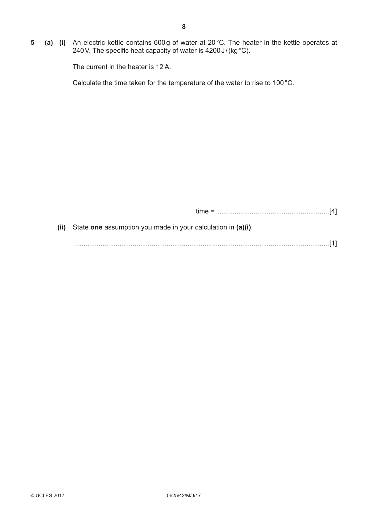
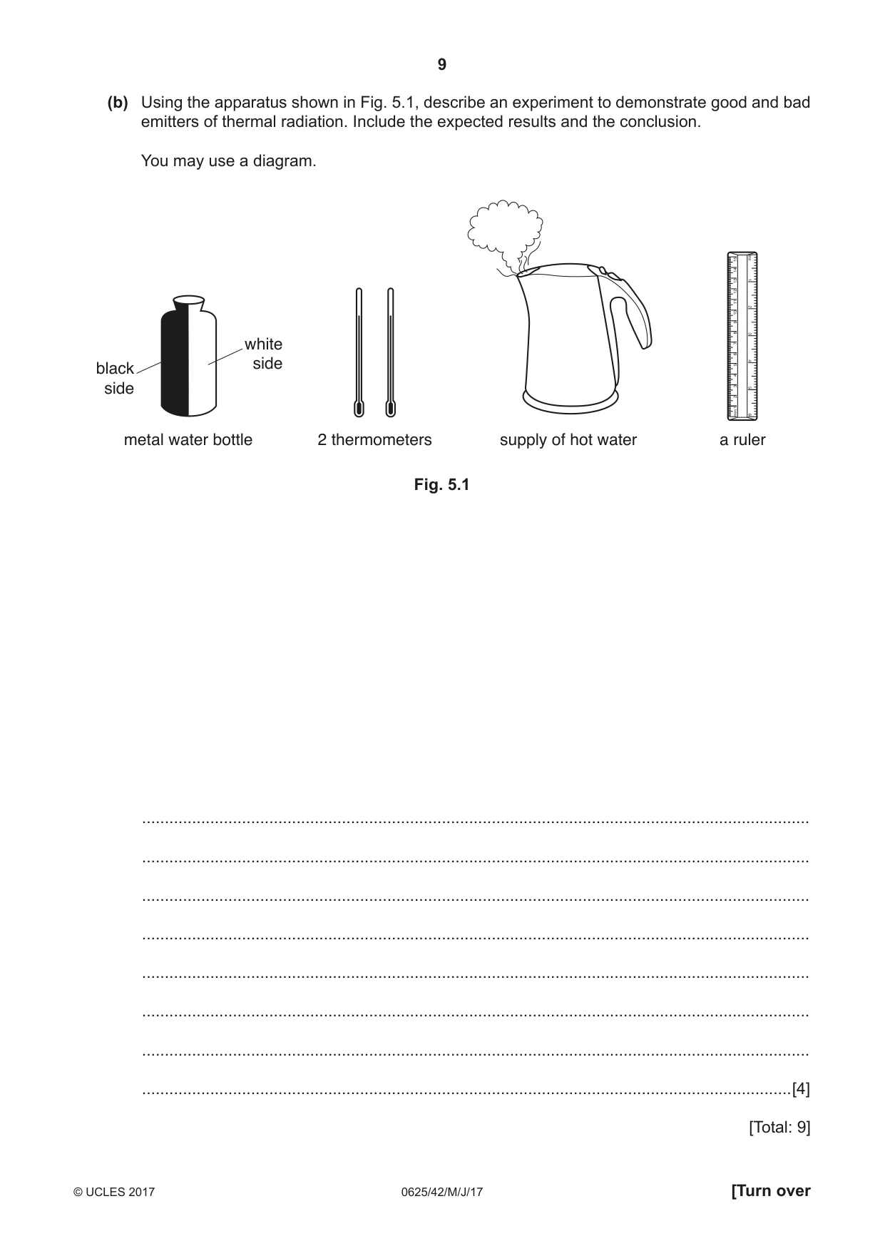
5 (a) (i) An electric kettle contains 600 g of water at 20 °C. The heater in the kettle operates at 240 V. The specific heat capacity of water is 4200 J / (kg °C). The current in the heater is 12 A. Calculate the time taken for the temperature of the water to rise to 100 °C. time = ...........................................................[4] (ii) State one assumption you made in your calculation in (a)(i). .......................................................................................................................................[1] (b) Using the apparatus shown in Fig. 5.1, describe an experiment to demonstrate good and bad emitters of thermal radiation. Include the expected results and the conclusion. You may use a diagram. white sideblack side metal water bottle 2 thermometers supply of hot water a ruler Fig. 5.1 ................................................................................................................................................... ................................................................................................................................................... ................................................................................................................................................... ................................................................................................................................................... ................................................................................................................................................... ................................................................................................................................................... ................................................................................................................................................... ...............................................................................................................................................[4] [Total: 9]
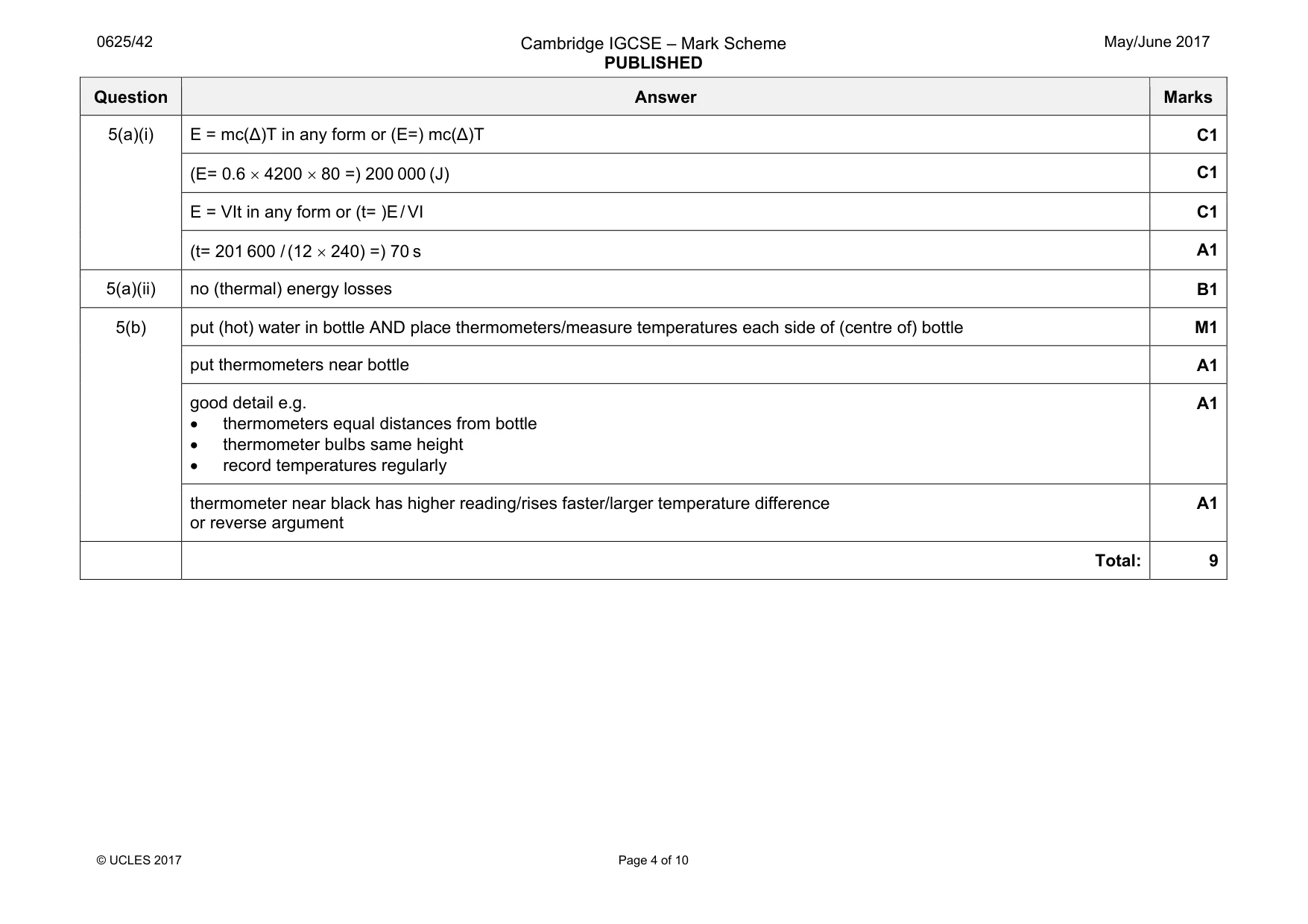
Mark scheme: 5(a)(i) E = mc(∆)T in any form or (E=) mc(∆)T C1 (E= 0.6 × 4200 × 80 =) 200 000 (J) C1 E = VIt in any form or (t= )E / VI C1 (t= 201 600 / (12 × 240) =) 70 s A1 5(a)(ii) no (thermal) energy losses B1 5(b) put (hot) water in bottle AND place thermometers/measure temperatures each side of (centre of) bottle M1 put thermometers near bottle A1 good detail e.g. • thermometers equal distances from bottle • thermometer bulbs same height • record temperatures regularly A1 thermometer near black has higher reading/rises faster/larger temperature difference or reverse argument A1 Total: 9
Q6 · The graph in Fig
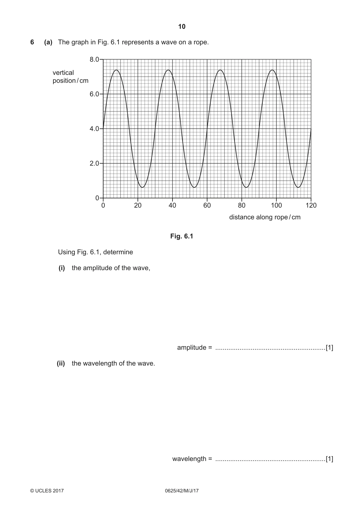
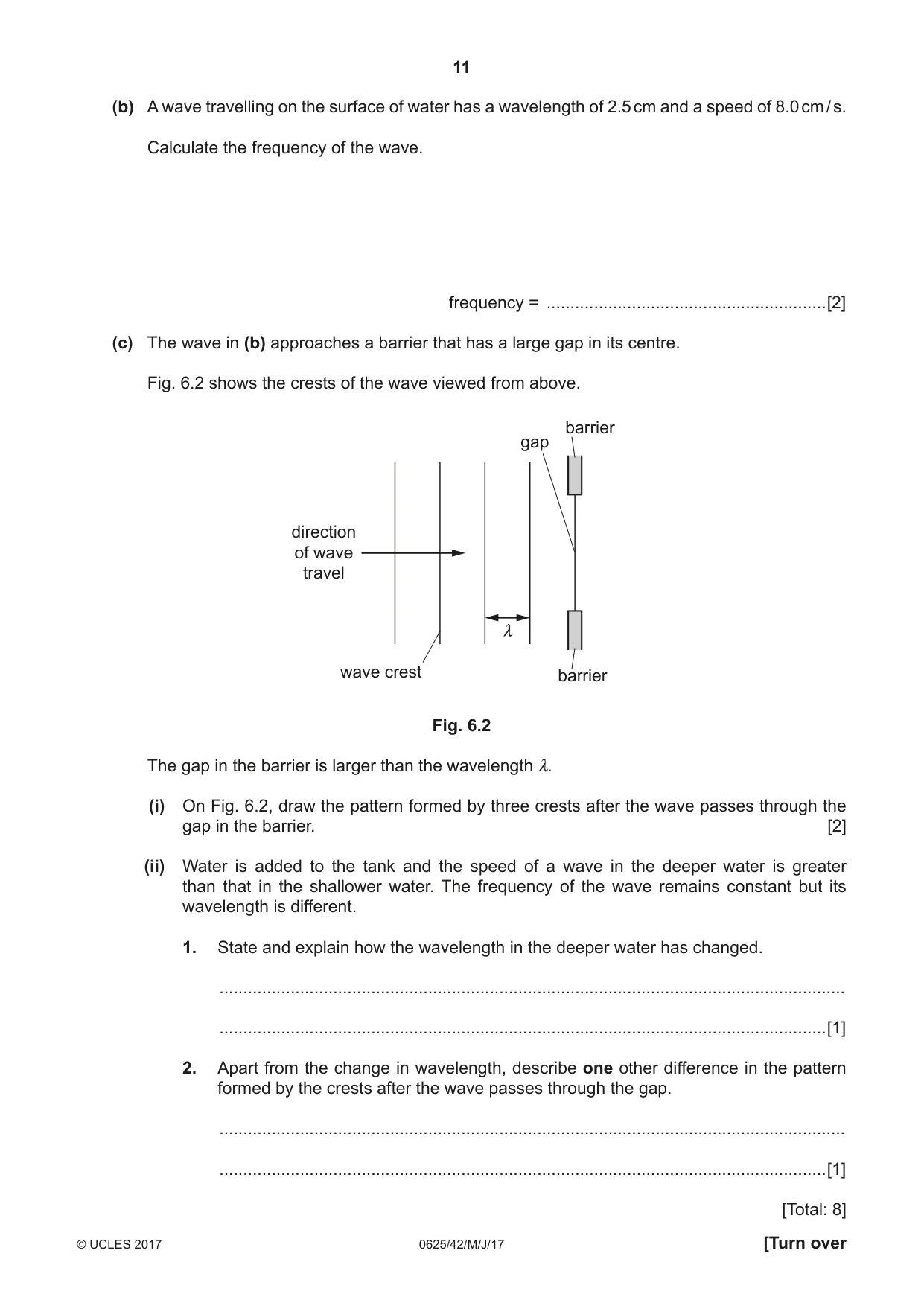
6 (a) The graph in Fig. 6.1 represents a wave on a rope. 8.0 vertical position / cm 6.0 4.0 2.0 0 0 20 40 60 80 100 120 distance along rope / cm Fig. 6.1 Using Fig. 6.1, determine (i) the amplitude of the wave, amplitude = ...........................................................[1] (ii) the wavelength of the wave. wavelength = ...........................................................[1] (b) A wave travelling on the surface of water has a wavelength of 2.5 cm and a speed of 8.0 cm / s. Calculate the frequency of the wave. frequency = ...........................................................[2] (c) The wave in (b) approaches a barrier that has a large gap in its centre. Fig. 6.2 shows the crests of the wave viewed from above. barrier gap direction of wave travel λ wave crest barrier Fig. 6.2 The gap in the barrier is larger than the wavelength λ. (i) On Fig. 6.2, draw the pattern formed by three crests after the wave passes through the gap in the barrier. [2] (ii) Water is added to the tank and the speed of a wave in the deeper water is greater than that in the shallower water. The frequency of the wave remains constant but its wavelength is different. 1. State and explain how the wavelength in the deeper water has changed. .................................................................................................................................... ................................................................................................................................[1] 2. Apart from the change in wavelength, describe one other difference in the pattern formed by the crests after the wave passes through the gap. .................................................................................................................................... ................................................................................................................................[1] [Total: 8]
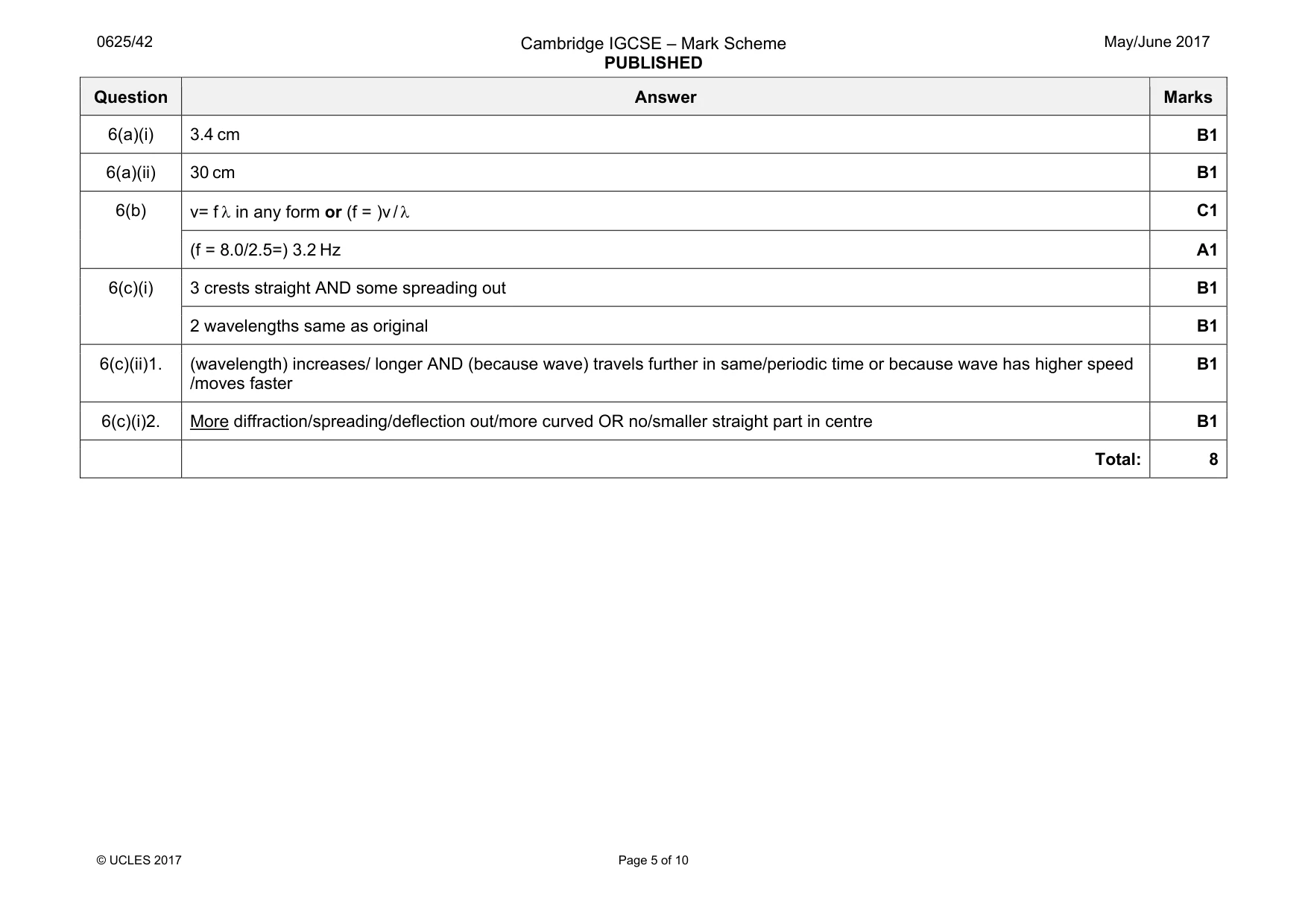
Mark scheme: 6(a)(i) 3.4 cm B1 6(a)(ii) 30 cm B1 6(b) v= f λ in any form or (f = )v / λ C1 (f = 8.0/2.5=) 3.2 Hz A1 6(c)(i) 3 crests straight AND some spreading out B1 2 wavelengths same as original B1 6(c)(ii)1. (wavelength) increases/ longer AND (because wave) travels further in same/periodic time or because wave has higher speed /moves faster B1 6(c)(i)2. More diffraction/spreading/deflection out/more curved OR no/smaller straight part in centre B1 Total: 8
Q7 · The speed of light in air is 3.0 # 108 m / s
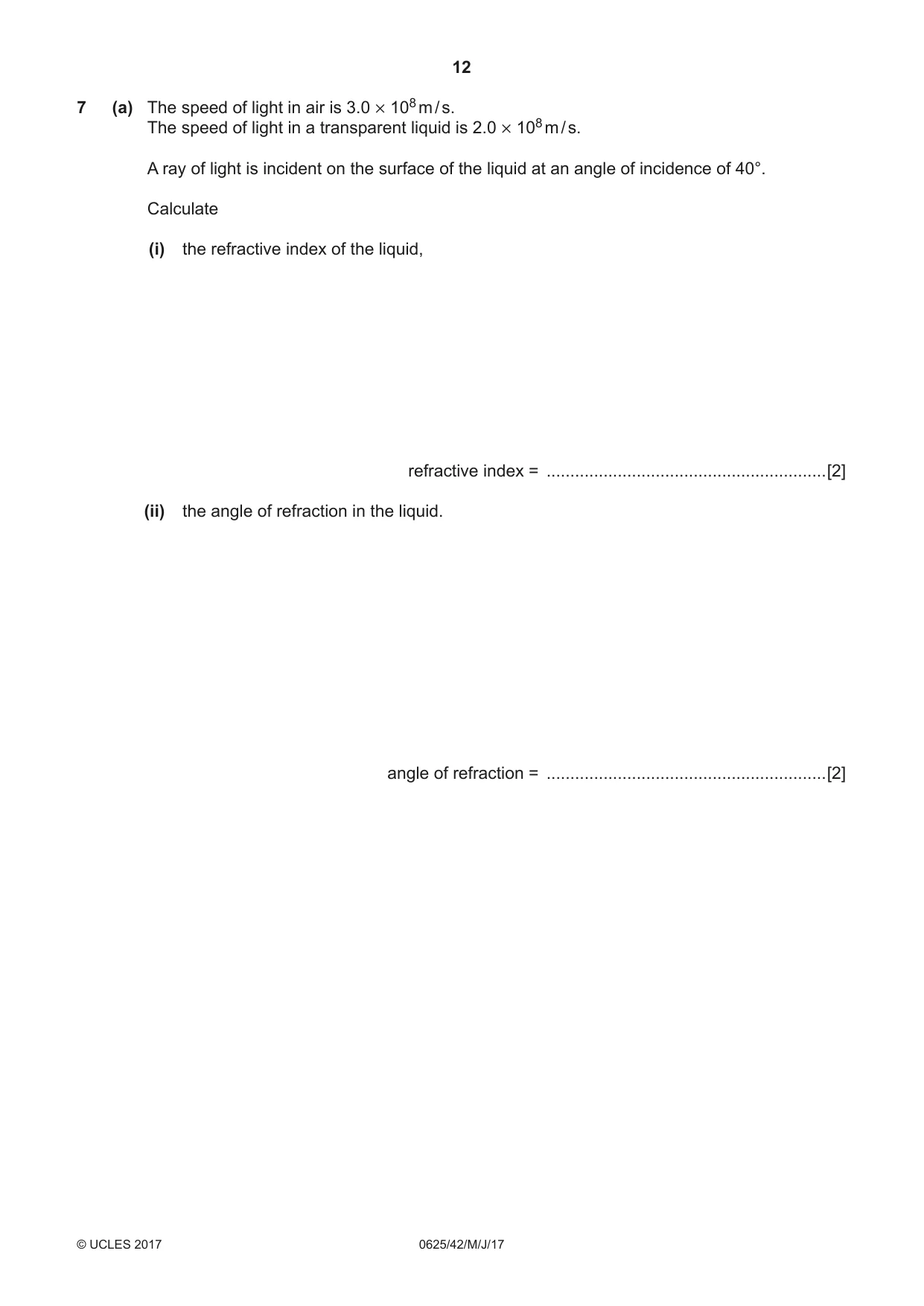
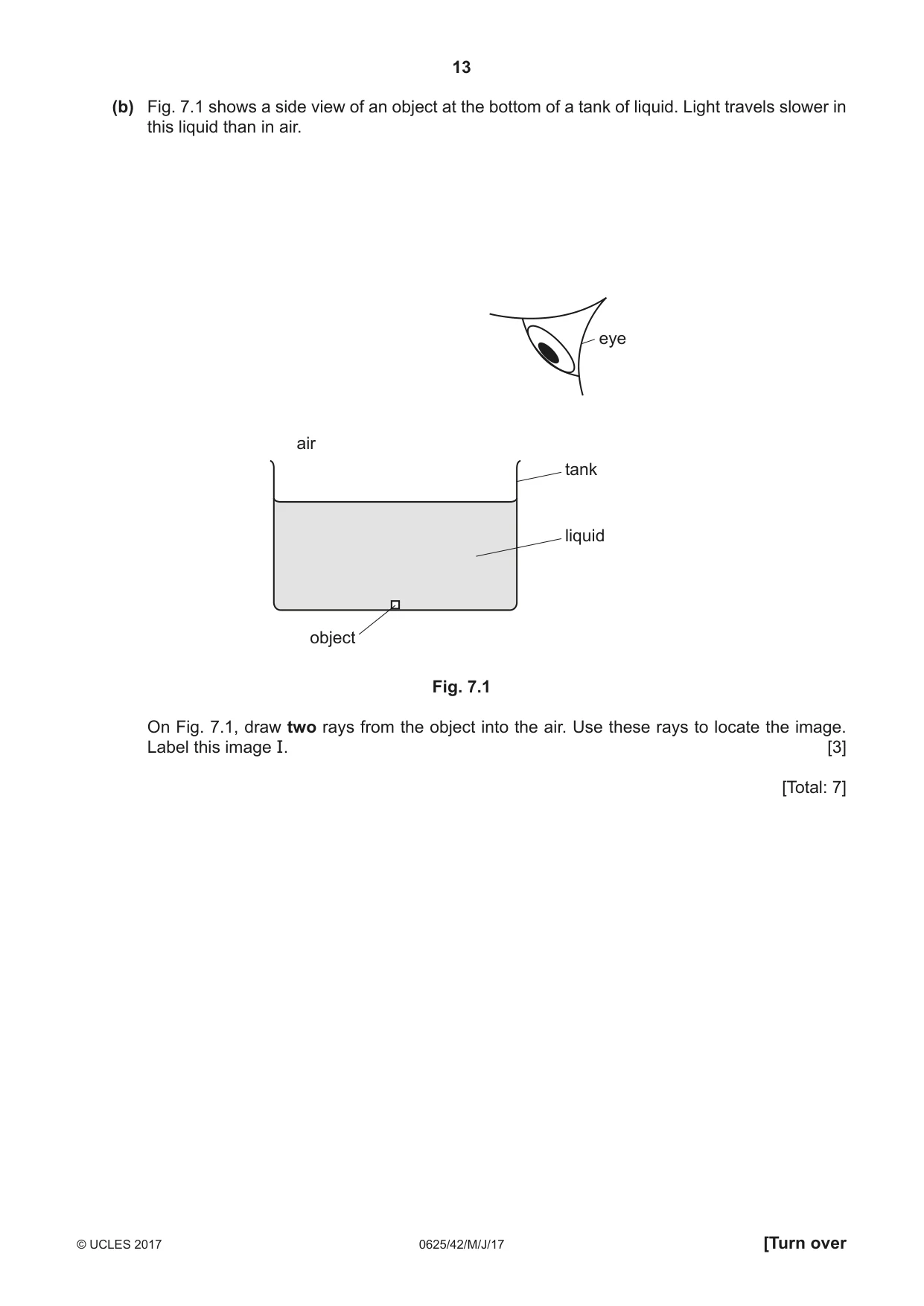
7 (a) The speed of light in air is 3.0 # 108 m / s. The speed of light in a transparent liquid is 2.0 # 108 m / s. A ray of light is incident on the surface of the liquid at an angle of incidence of 40°. Calculate (i) the refractive index of the liquid, refractive index = ...........................................................[2] (ii) the angle of refraction in the liquid. angle of refraction = ...........................................................[2] (b) Fig. 7.1 shows a side view of an object at the bottom of a tank of liquid. Light travels slower in this liquid than in air. eye air tank liquid object Fig. 7.1 On Fig. 7.1, draw two rays from the object into the air. Use these rays to locate the image. Label this image I. [3] [Total: 7]
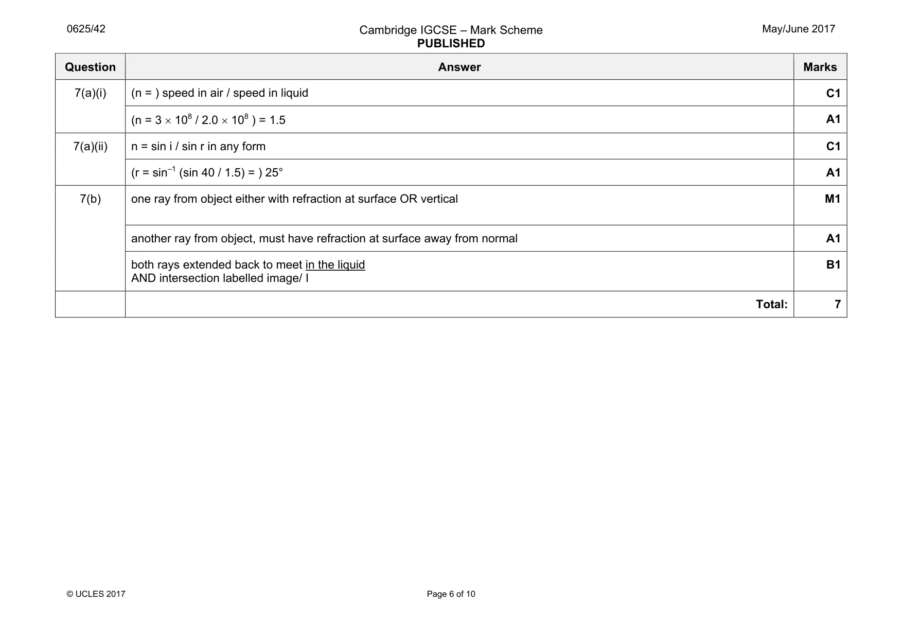
Mark scheme: 7(a)(i) (n = ) speed in air / speed in liquid C1 (n = 3 × 10⁸ / 2.0 × 10⁸ ) = 1.5 A1 7(a)(ii) n = sin i / sin r in any form C1 (r = sin–1 (sin 40 / 1.5) = ) 25° A1 7(b) one ray from object either with refraction at surface OR vertical M1 another ray from object, must have refraction at surface away from normal A1 both rays extended back to meet in the liquid AND intersection labelled image/ I B1 Total: 7
Q8 · A 12.0 V power supply connected in a circuit
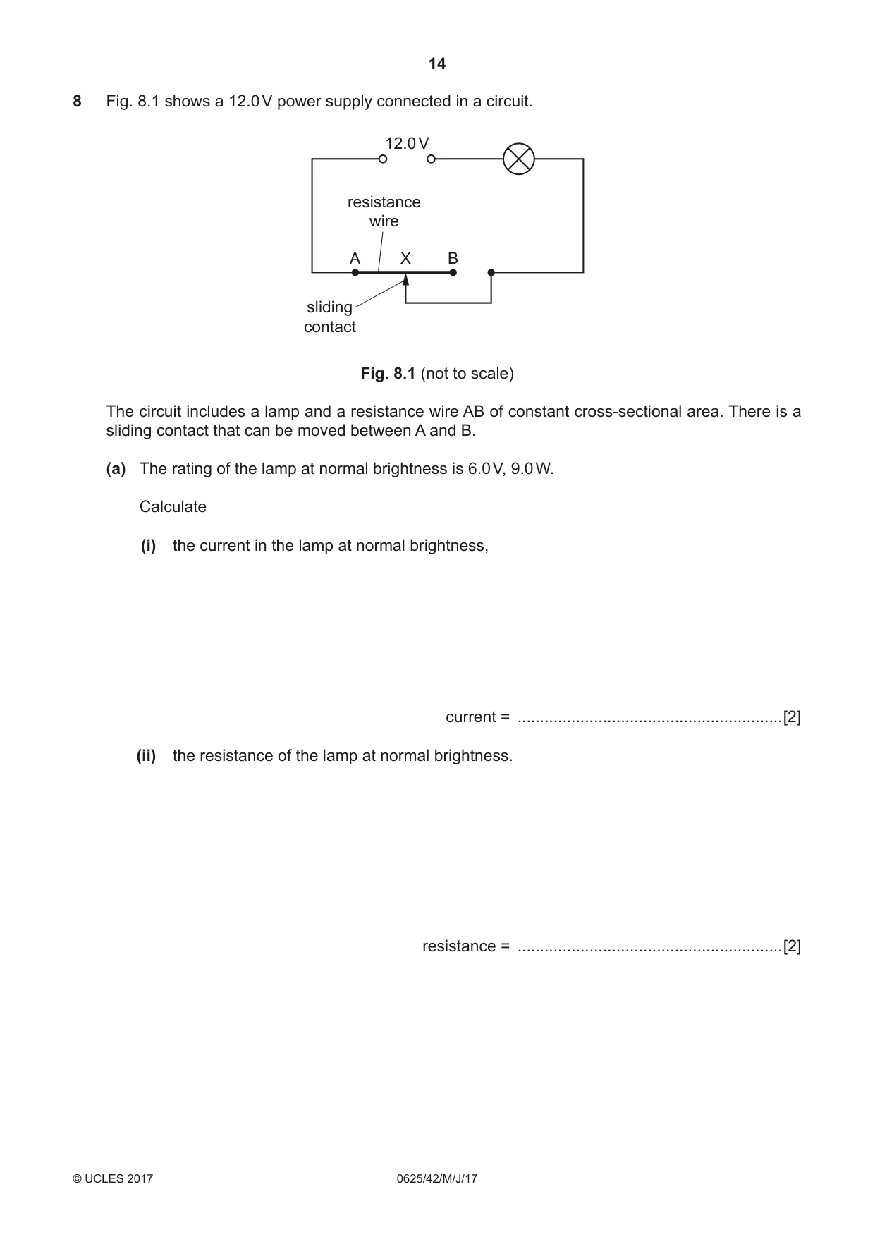
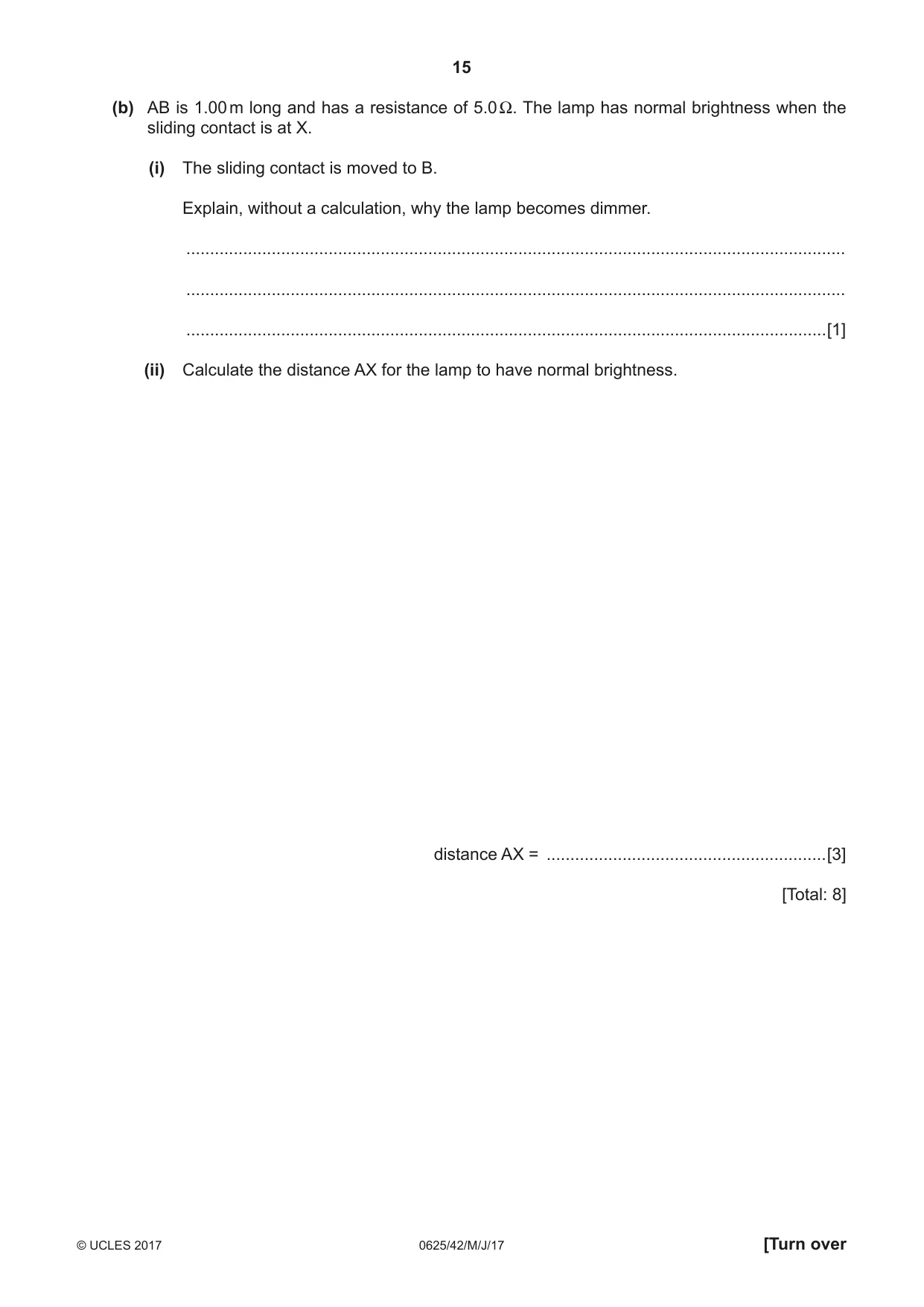
8 Fig. 8.1 shows a 12.0 V power supply connected in a circuit. 12.0 V resistance wire A X B sliding contact Fig. 8.1 (not to scale) The circuit includes a lamp and a resistance wire AB of constant cross-sectional area. There is a sliding contact that can be moved between A and B. (a) The rating of the lamp at normal brightness is 6.0 V, 9.0 W. Calculate (i) the current in the lamp at normal brightness, current = ...........................................................[2] (ii) the resistance of the lamp at normal brightness. resistance = ...........................................................[2] (b) AB is 1.00 m long and has a resistance of 5.0 Ω. The lamp has normal brightness when the sliding contact is at X. (i) The sliding contact is moved to B. Explain, without a calculation, why the lamp becomes dimmer. ........................................................................................................................................... ........................................................................................................................................... .......................................................................................................................................[1] (ii) Calculate the distance AX for the lamp to have normal brightness. distance AX = ...........................................................[3] [Total: 8]
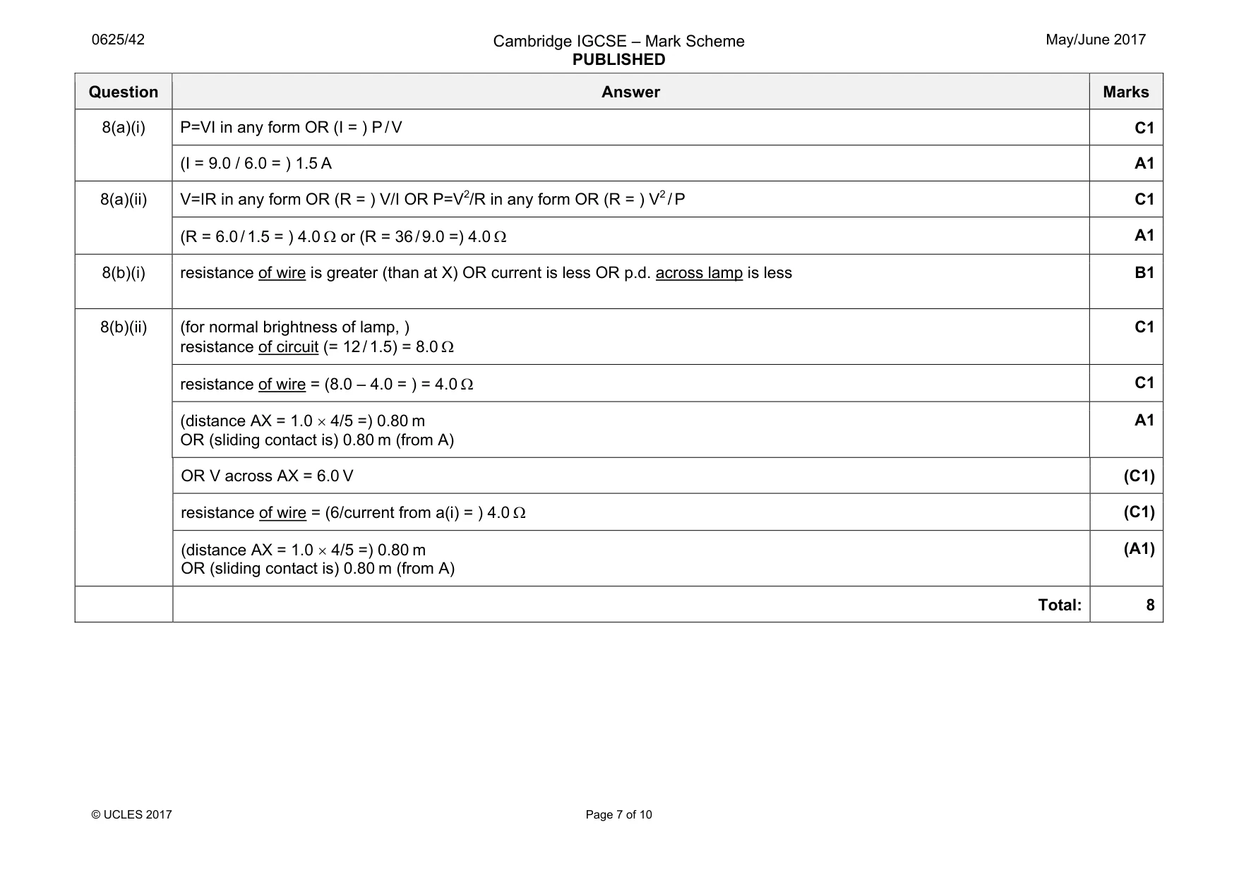
Mark scheme: 8(a)(i) P=VI in any form OR (I = ) P / V C1 (I = 9.0 / 6.0 = ) 1.5 A A1 8(a)(ii) V=IR in any form OR (R = ) V/I OR P=V2/R in any form OR (R = ) V2 / P C1 (R = 6.0 / 1.5 = ) 4.0 Ω or (R = 36 / 9.0 =) 4.0 Ω A1 8(b)(i) resistance of wire is greater (than at X) OR current is less OR p.d. across lamp is less B1 8(b)(ii) (for normal brightness of lamp, ) resistance of circuit (= 12 / 1.5) = 8.0 Ω C1 resistance of wire = (8.0 – 4.0 = ) = 4.0 Ω C1 (distance AX = 1.0 × 4/5 =) 0.80 m OR (sliding contact is) 0.80 m (from A) A1 OR V across AX = 6.0 V (C1) resistance of wire = (6/current from a(i) = ) 4.0 Ω (C1) (distance AX = 1.0 × 4/5 =) 0.80 m OR (sliding contact is) 0.80 m (from A) (A1) Total: 8
Q9 · A horizontal wire PQ placed in the gap between the N pole and the S pole of a magnet
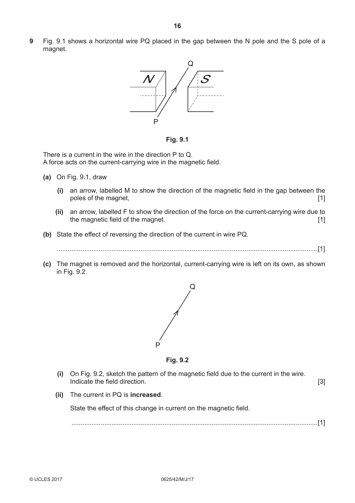
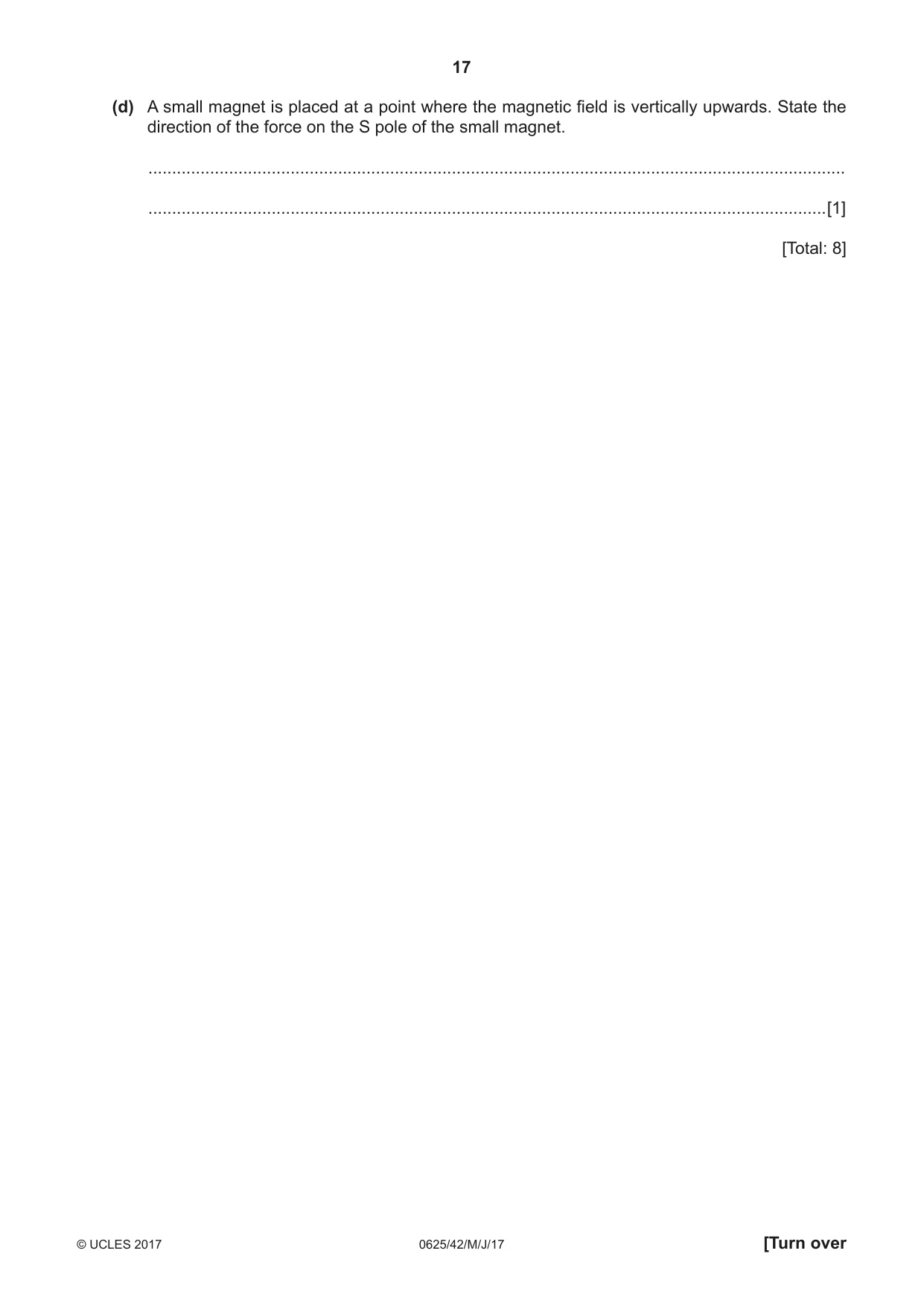
9 Fig. 9.1 shows a horizontal wire PQ placed in the gap between the N pole and the S pole of a magnet. Q N S P Fig. 9.1 There is a current in the wire in the direction P to Q. A force acts on the current-carrying wire in the magnetic field. (a) On Fig. 9.1, draw (i) an arrow, labelled M to show the direction of the magnetic field in the gap between the poles of the magnet, [1] (ii) an arrow, labelled F to show the direction of the force on the current-carrying wire due to the magnetic field of the magnet. [1] (b) State the effect of reversing the direction of the current in wire PQ. ...............................................................................................................................................[1] (c) The magnet is removed and the horizontal, current-carrying wire is left on its own, as shown in Fig. 9.2. Q P Fig. 9.2 (i) On Fig. 9.2, sketch the pattern of the magnetic field due to the current in the wire. Indicate the field direction. [3] (ii) The current in PQ is increased. State the effect of this change in current on the magnetic field. .......................................................................................................................................[1] (d) A small magnet is placed at a point where the magnetic field is vertically upwards. State the direction of the force on the S pole of the small magnet. ................................................................................................................................................... ...............................................................................................................................................[1] [Total: 8]
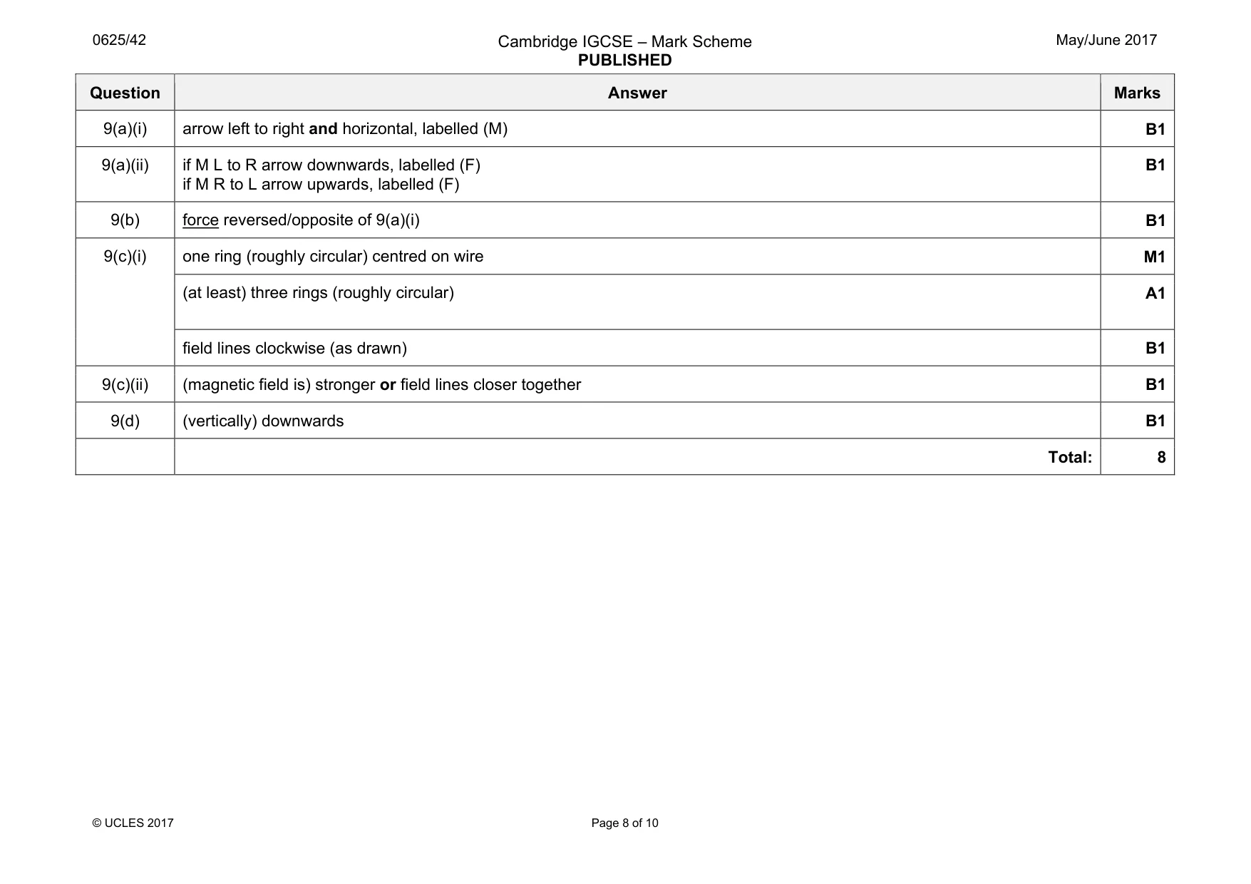
Mark scheme: 9(a)(i) arrow left to right and horizontal, labelled (M) B1 9(a)(ii) if M L to R arrow downwards, labelled (F) if M R to L arrow upwards, labelled (F) B1 9(b) force reversed/opposite of 9(a)(i) B1 9(c)(i) one ring (roughly circular) centred on wire M1 (at least) three rings (roughly circular) A1 field lines clockwise (as drawn) B1 9(c)(ii) (magnetic field is) stronger or field lines closer together B1 9(d) (vertically) downwards B1 Total: 8 Que estion Answer Ma arks
Q11 · The arrows in Fig
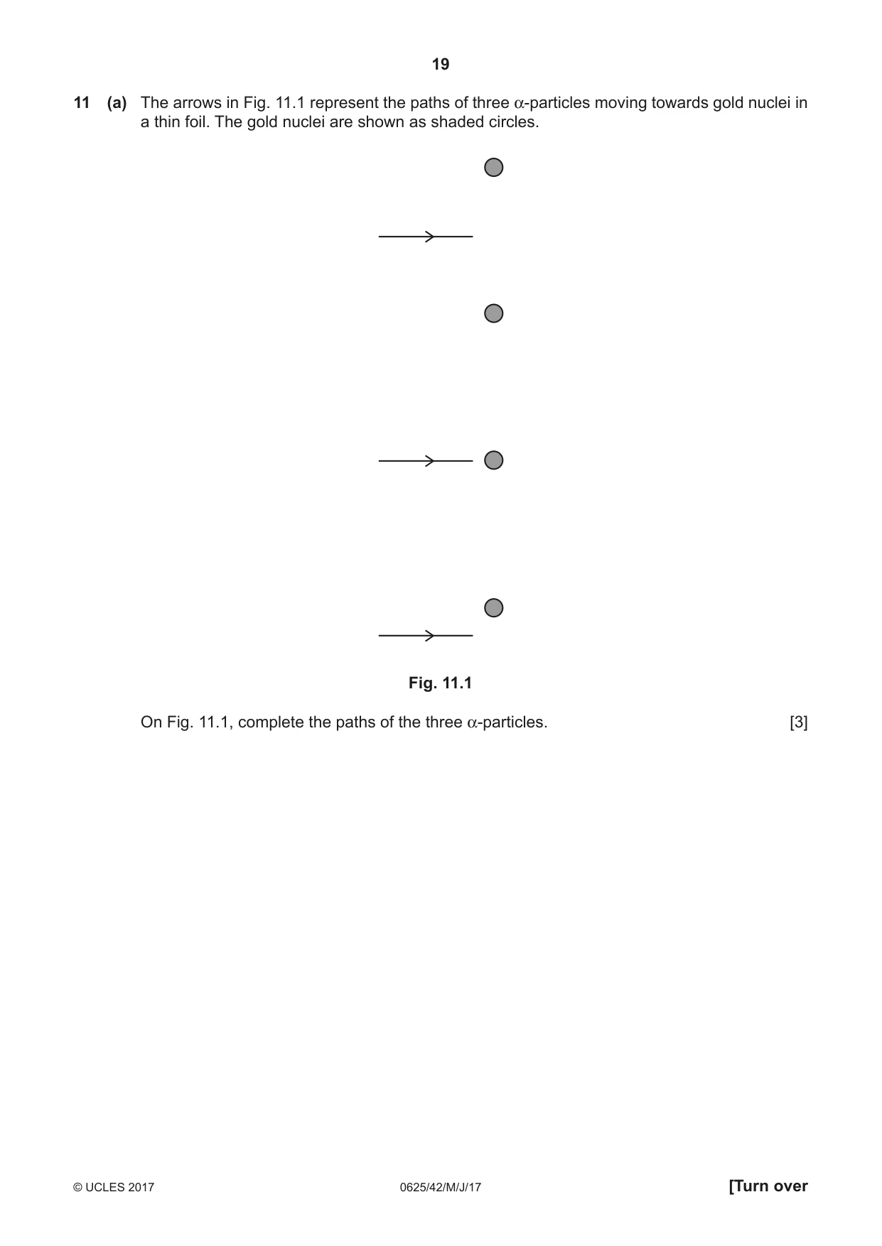
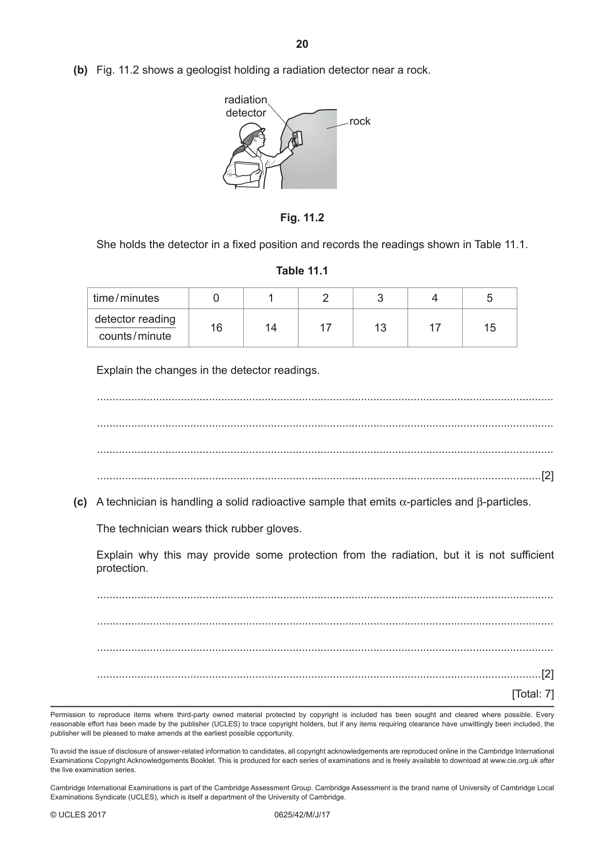
11 (a) The arrows in Fig. 11.1 represent the paths of three α-particles moving towards gold nuclei in a thin foil. The gold nuclei are shown as shaded circles. Fig. 11.1 On Fig. 11.1, complete the paths of the three α-particles. [3] (b) Fig. 11.2 shows a geologist holding a radiation detector near a rock. radiation detector rock Fig. 11.2 She holds the detector in a fixed position and records the readings shown in Table 11.1. Table 11.1 time / minutes 0 1 2 3 4 5 detector reading 16 14 17 13 17 15 counts / minute Explain the changes in the detector readings. ................................................................................................................................................... ................................................................................................................................................... ................................................................................................................................................... ...............................................................................................................................................[2] (c) A technician is handling a solid radioactive sample that emits α-particles and β-particles. The technician wears thick rubber gloves. Explain why this may provide some protection from the radiation, but it is not sufficient protection. ................................................................................................................................................... ................................................................................................................................................... ................................................................................................................................................... ...............................................................................................................................................[2] [Total: 7]
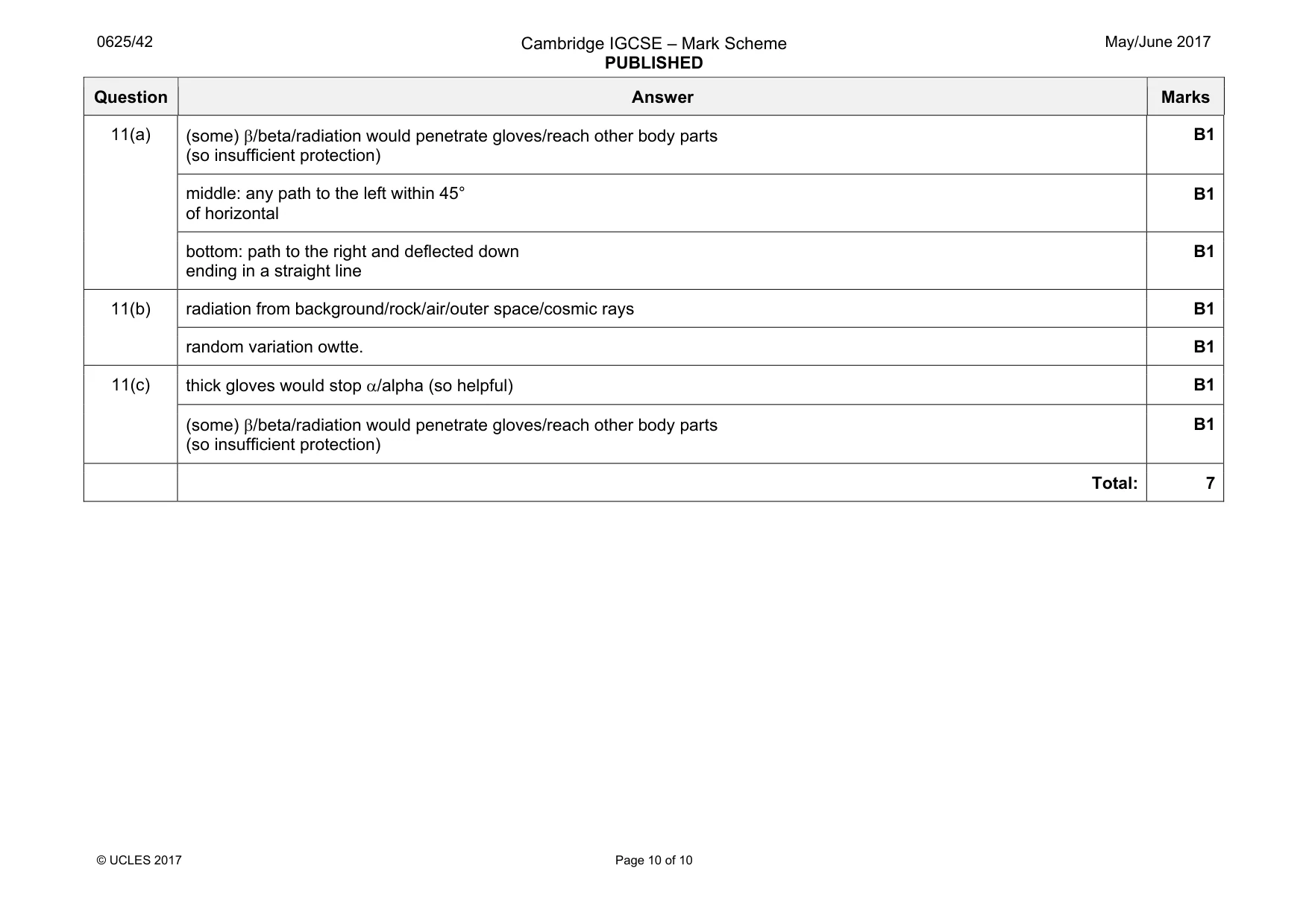
Mark scheme: 11(a) (so insufficient protection) B1 middle: any path to the left within 45° of horizontal B1 bottom: path to the right and deflected down ending in a straight line B1 11(b) radiation from background/rock/air/outer space/cosmic rays B1 random variation owtte. B1 11(c) thick gloves would stop α/alpha (so helpful) B1 (some) β/beta/radiation would penetrate gloves/reach other body parts (so insufficient protection) B1 Total: 7
What was in this paper
The subtopics covered by these 10 questions, and how many questions each got. Open one in a new tab to see every Cambridge question on it.
What you needed in this session
Cambridge’s own grade thresholds for 2017 May/June, Paper 4 · Variant 2. A higher threshold means an easier paper — the bar moves with how the cohort did.