Cambridge IGCSE Design and Technology 0445 — 2024 May/June Paper 3 · Variant 2
0445/32/M/J/24 · 13 questions · 50 marks · 60 min
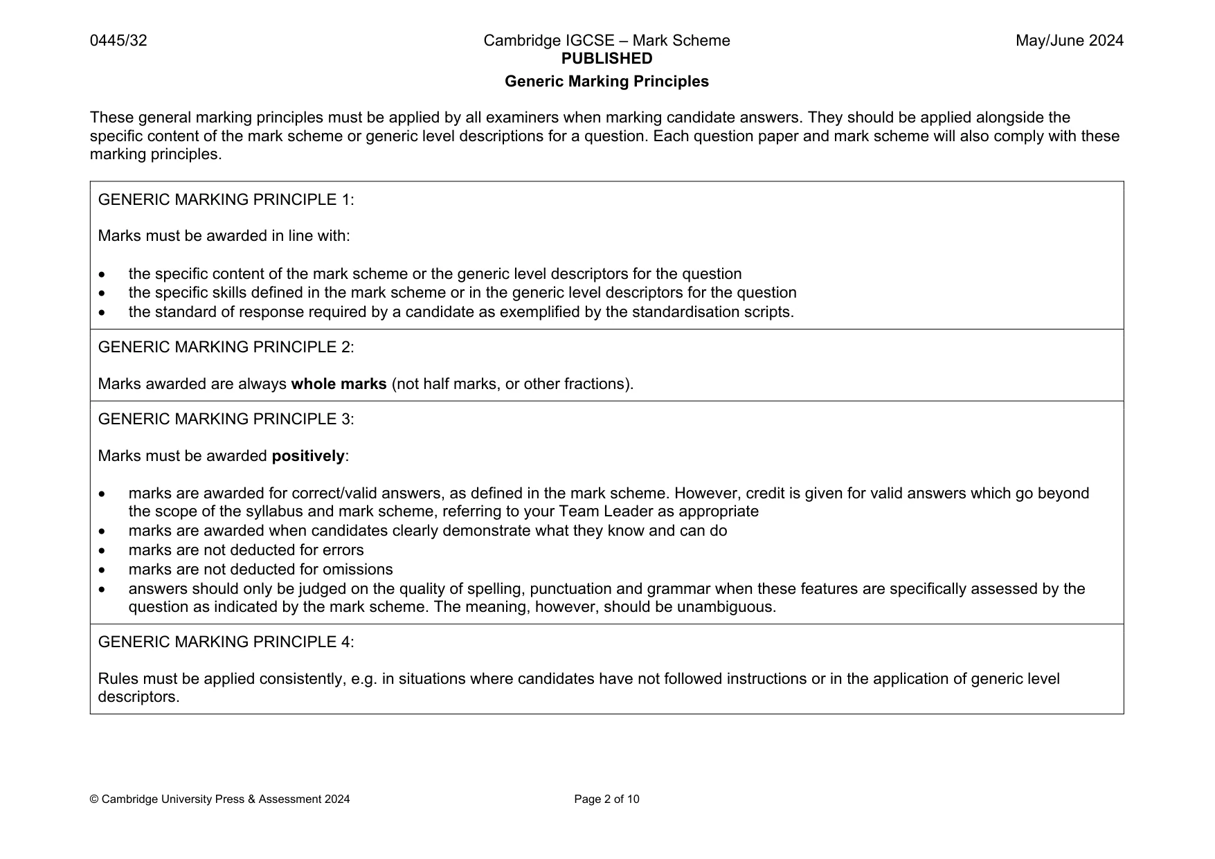
The question paper and its mark scheme, free to read here and free to download. This is Cambridge’s own paper, exactly as it was sat.
Question paper24 pages
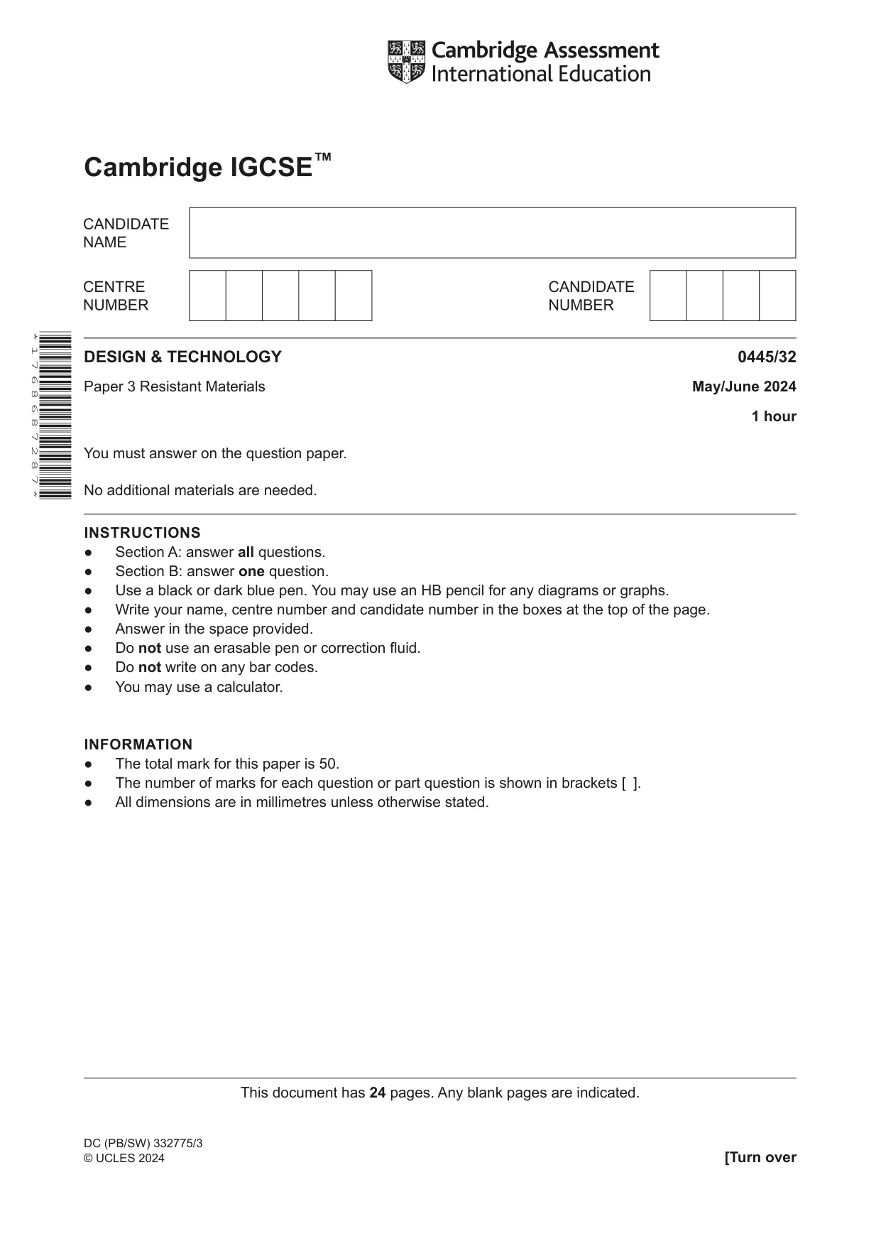

Mark scheme10 pages
Answers below. Sit the paper first if you are practising.
Questions as text
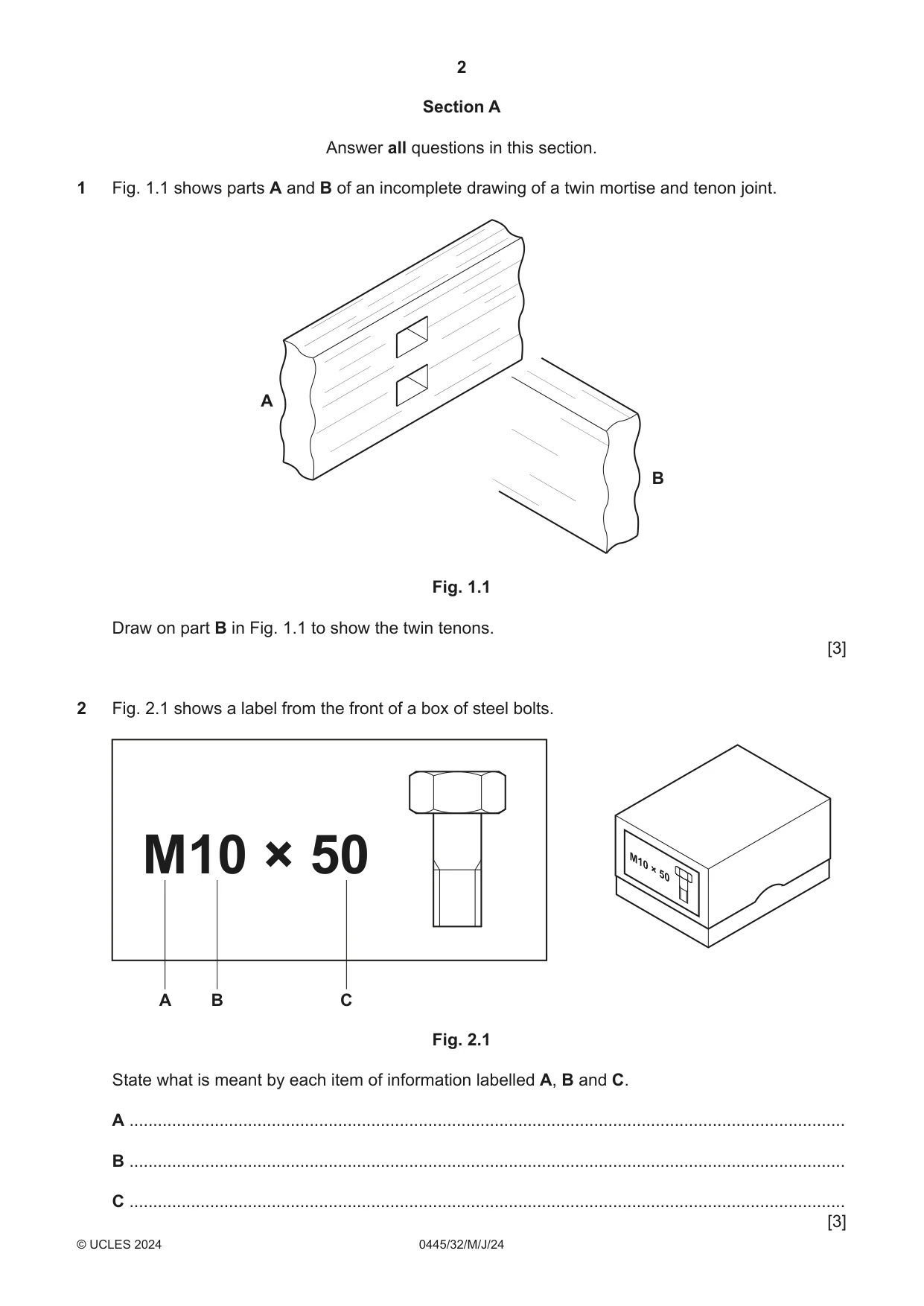
Q1 · Parts A and B of an incomplete drawing of a twin mortise and tenon joint
1 Fig. 1.1 shows parts A and B of an incomplete drawing of a twin mortise and tenon joint. A B Fig. 1.1 Draw on part B in Fig. 1.1 to show the twin tenons. [3]
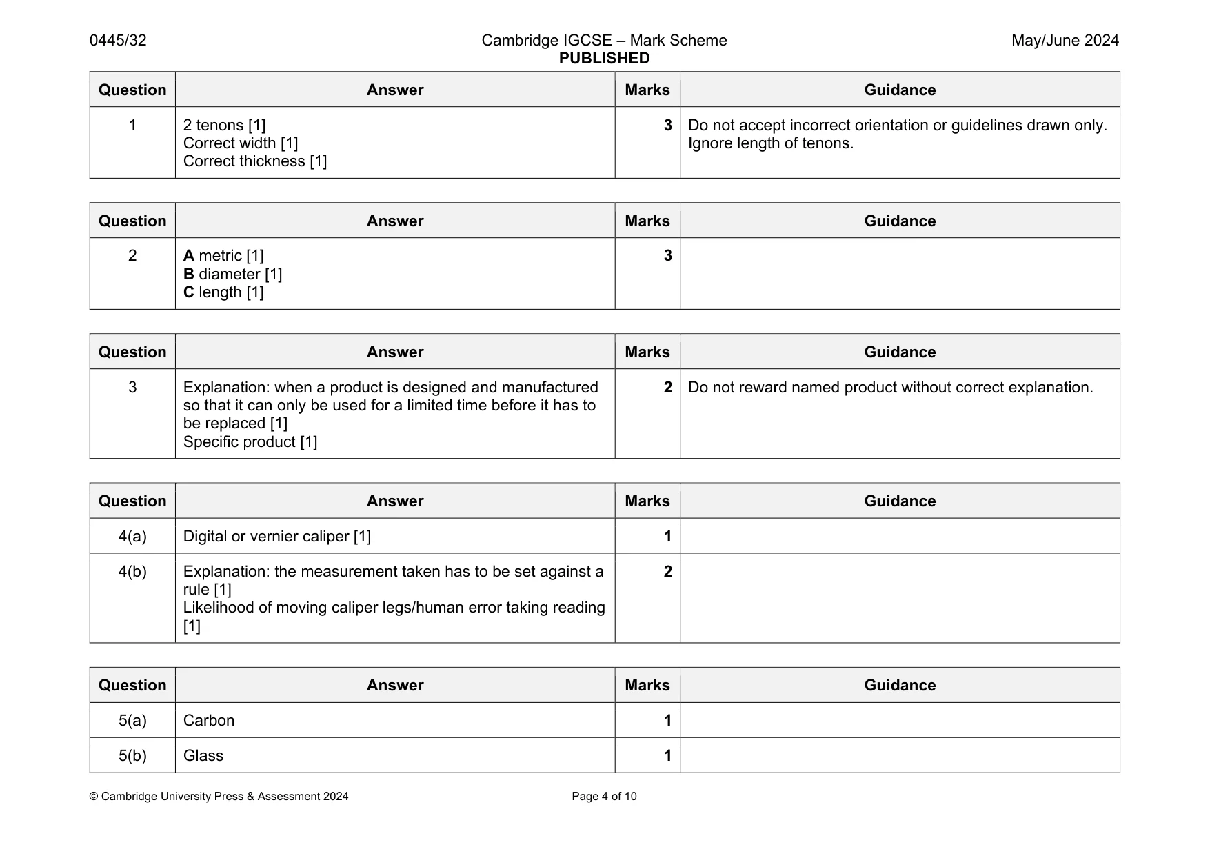
Mark scheme: 1 2 tenons [1] Correct width [1] Correct thickness [1] 3 Do not accept incorrect orientation or guidelines drawn only. Ignore length of tenons.
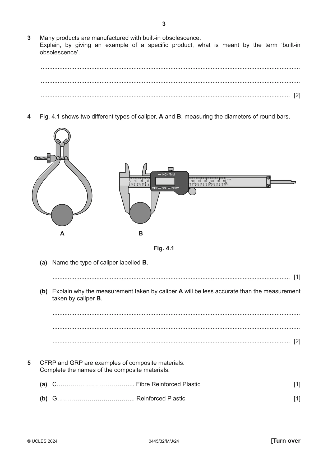
Q2 · A label from the front of a box of steel bolts
2 Fig. 2.1 shows a label from the front of a box of steel bolts. M10 × 50 A B C Fig. 2.1 State what is meant by each item of information labelled A, B and C. A ....................................................................................................................................................... B ....................................................................................................................................................... C ....................................................................................................................................................... [3]
Mark scheme: 2 A metric [1] B diameter [1] C length [1] 3
Q3 · Many products are manufactured with built-in obsolescence
3 Many products are manufactured with built-in obsolescence. Explain, by giving an example of a specific product, what is meant by the term ‘built-in obsolescence’. .......................................................................................................................................................... .......................................................................................................................................................... .................................................................................................................................................... [2]
Mark scheme: 3 Explanation: when a product is designed and manufactured so that it can only be used for a limited time before it has to be replaced [1] Specific product [1] 2 Do not reward named product without correct explanation.
Q4 · Two different types of caliper, A and B, measuring the diameters of round bars
4 Fig. 4.1 shows two different types of caliper, A and B, measuring the diameters of round bars. A B Fig. 4.1 (a) Name the type of caliper labelled B. ............................................................................................................................................. [1] (b) Explain why the measurement taken by caliper A will be less accurate than the measurement taken by caliper B. ................................................................................................................................................... ................................................................................................................................................... ............................................................................................................................................. [2]
Mark scheme: 4(a) Digital or vernier caliper [1] 1 4(b) Explanation: the measurement taken has to be set against a rule [1] Likelihood of moving caliper legs/human error taking reading [1] 2
Q5 · CFRP and GRP are examples of composite materials
5 CFRP and GRP are examples of composite materials. Complete the names of the composite materials. (a) C………………………………... Fibre Reinforced Plastic [1] (b) G………………………………... Reinforced Plastic [1]
Mark scheme: 5(a) Carbon 1 5(b) Glass 1
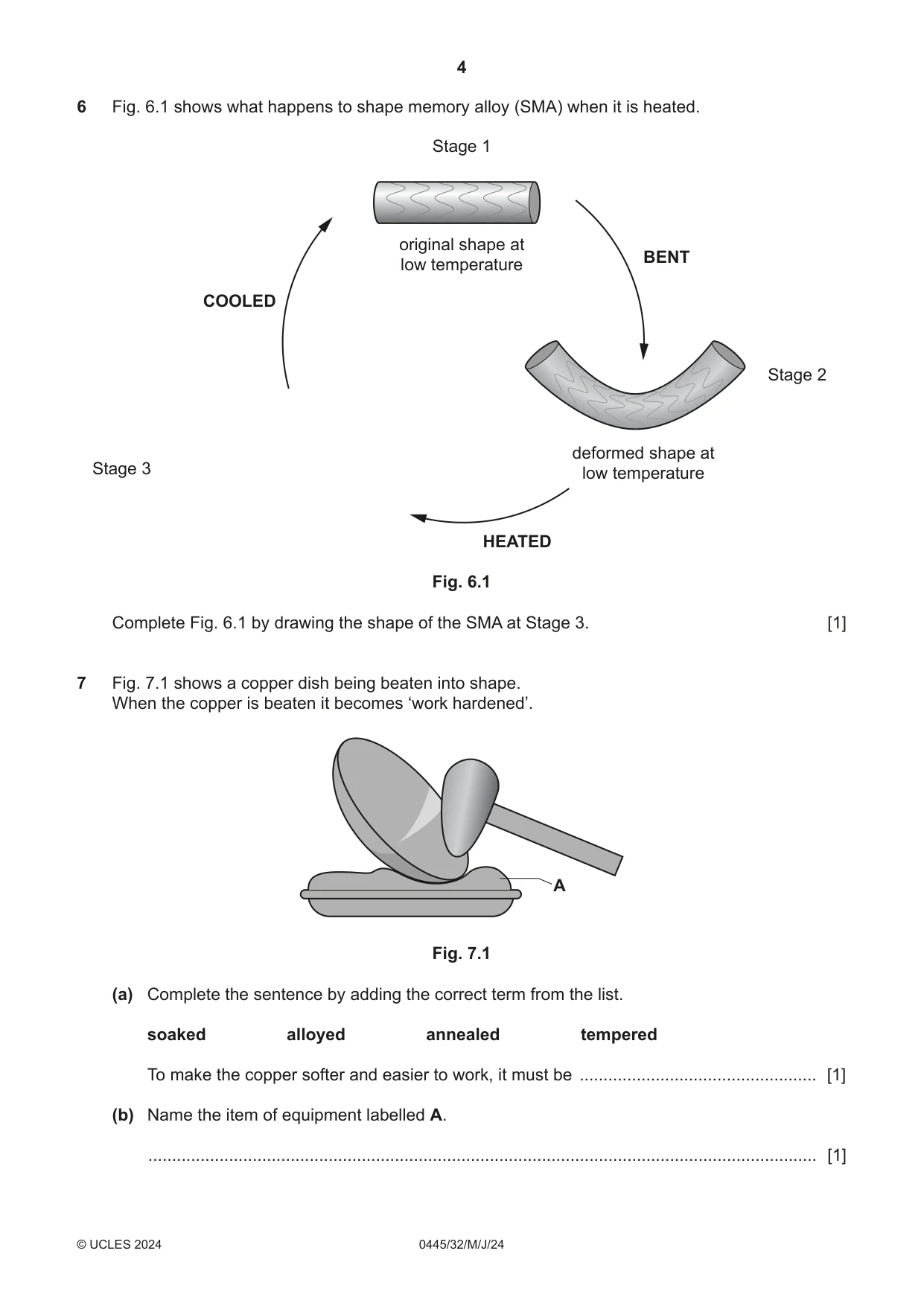
Q6 · What happens to shape memory alloy (SMA) when it is heated
6 Fig. 6.1 shows what happens to shape memory alloy (SMA) when it is heated. Stage 1 original shape at BENT low temperature COOLED Stage 2 deformed shape at Stage 3 low temperature HEATED Fig. 6.1 Complete Fig. 6.1 by drawing the shape of the SMA at Stage 3. [1]
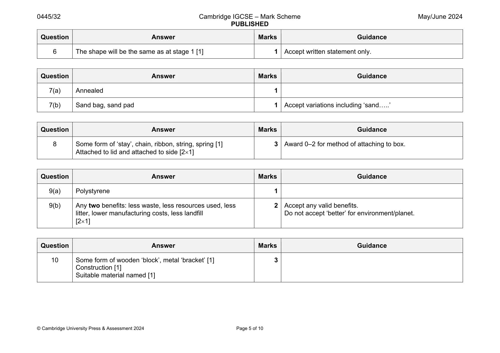
Mark scheme: 6 The shape will be the same as at stage 1 [1] 1 Accept written statement only.
Q7 · A copper dish being beaten into shape
7 Fig. 7.1 shows a copper dish being beaten into shape. When the copper is beaten it becomes ‘work hardened’. A Fig. 7.1 (a) Complete the sentence by adding the correct term from the list. soaked alloyed annealed tempered To make the copper softer and easier to work, it must be .................................................. [1] (b) Name the item of equipment labelled A. ............................................................................................................................................. [1]
Mark scheme: 7(a) Annealed 1 7(b) Sand bag, sand pad 1 Accept variations including ‘sand…..’
Q8 · A hardwood box with a hinged lid
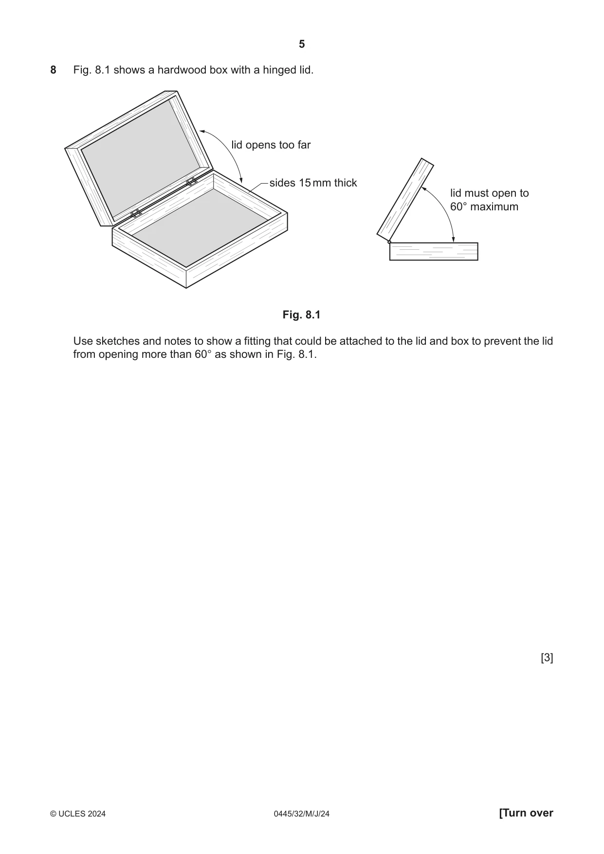
8 Fig. 8.1 shows a hardwood box with a hinged lid. lid opens too far sides 15 mm thick lid must open to 60° maximum Fig. 8.1 Use sketches and notes to show a fitting that could be attached to the lid and box to prevent the lid from opening more than 60° as shown in Fig. 8.1. [3]
Mark scheme: 8 Some form of ‘stay’, chain, ribbon, string, spring [1] Attached to lid and attached to side [21]
Q9 · A plastic vending cup and the symbol for the plastic from which the cup is made
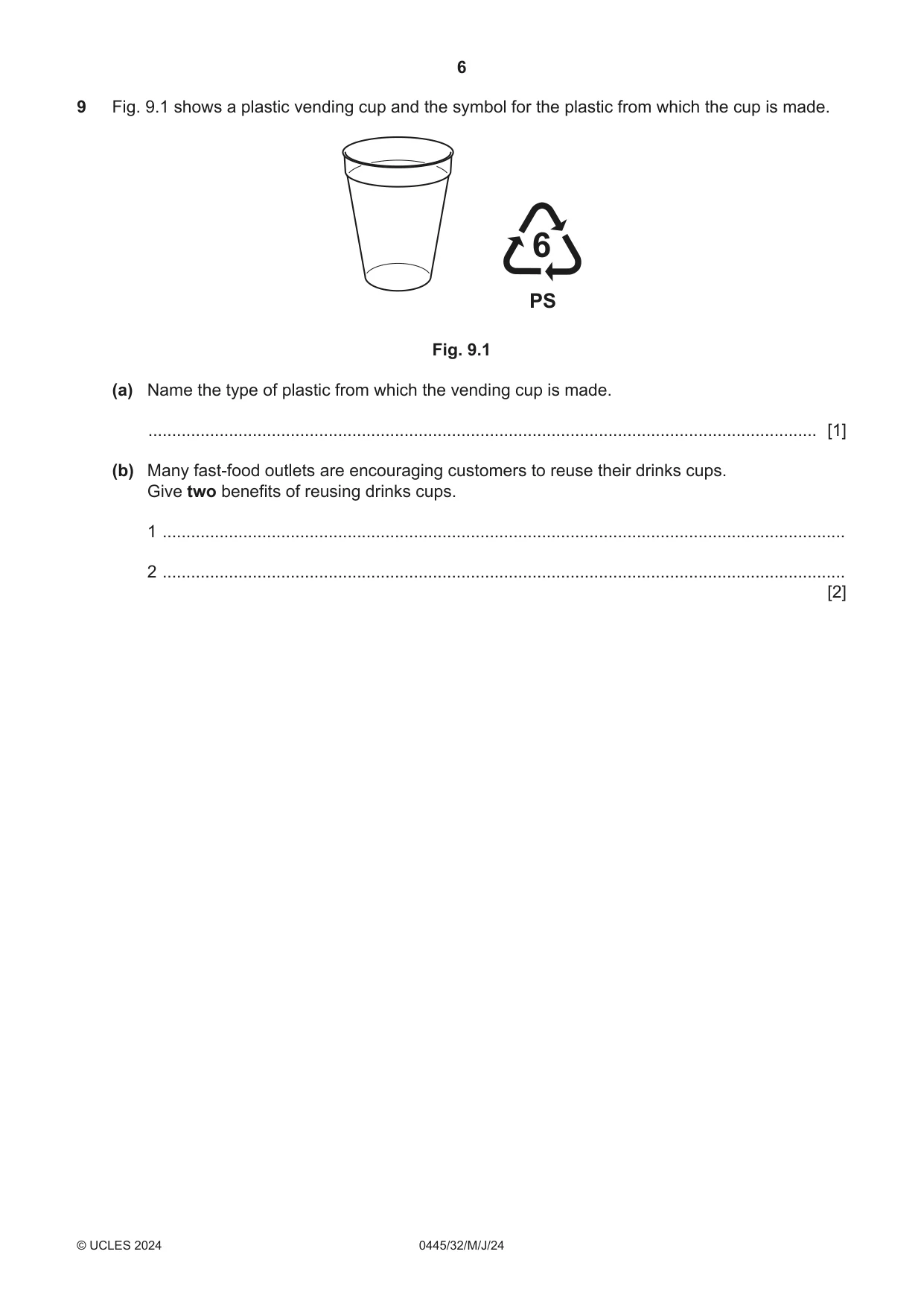
9 Fig. 9.1 shows a plastic vending cup and the symbol for the plastic from which the cup is made. PS Fig. 9.1 (a) Name the type of plastic from which the vending cup is made. ............................................................................................................................................. [1] (b) Many fast-food outlets are encouraging customers to reuse their drinks cups. Give two benefits of reusing drinks cups. 1 ................................................................................................................................................ 2 ................................................................................................................................................ [2]
Mark scheme: 9(a) Polystyrene 1 9(b) Any two benefits: less waste, less resources used, less litter, lower manufacturing costs, less landfill [21] 2 Accept any valid benefits. Do not accept ‘better’ for environment/planet.
Q10 · Part of an incomplete design for a towel rack
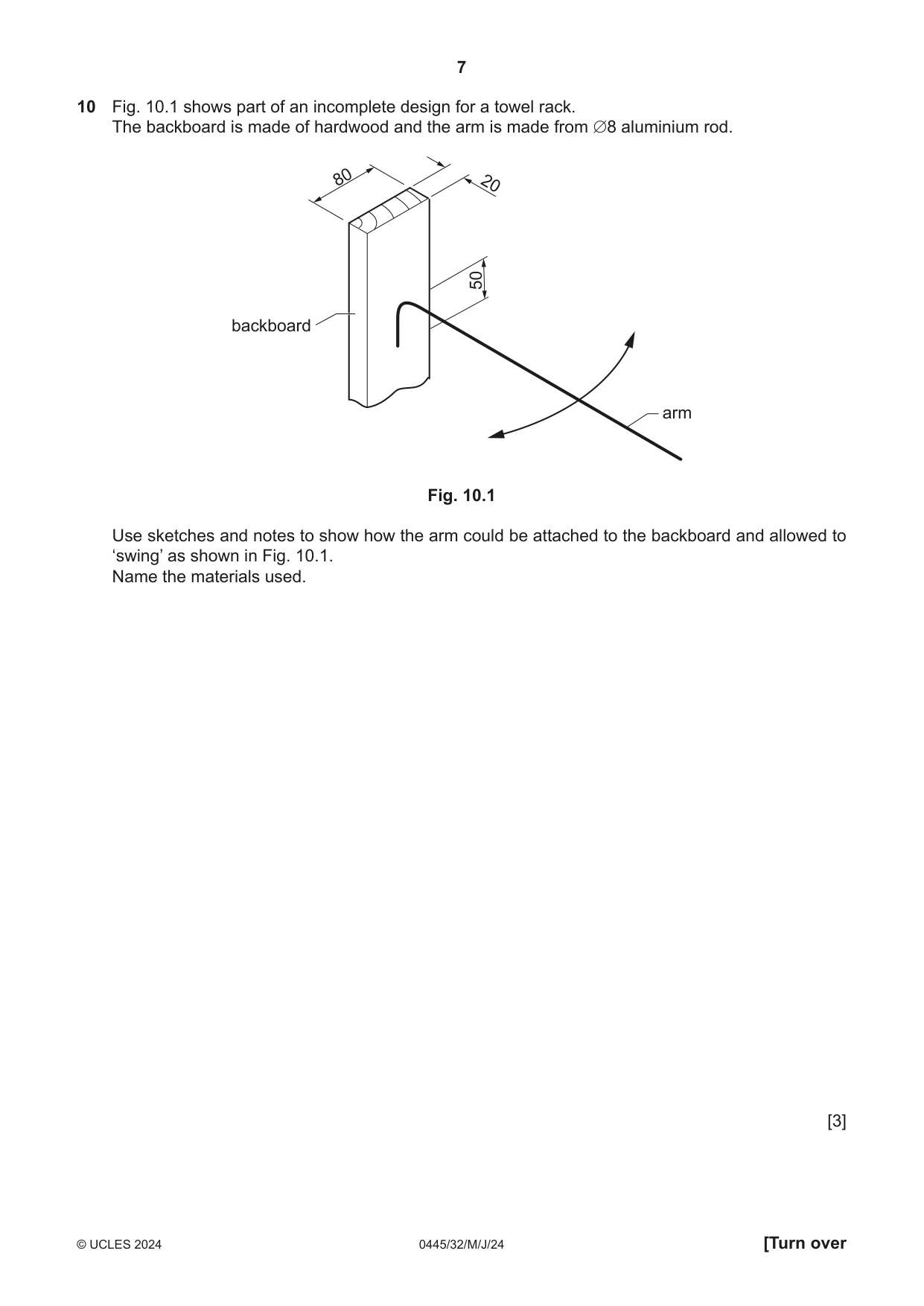
10 Fig. 10.1 shows part of an incomplete design for a towel rack. The backboard is made of hardwood and the arm is made from ∅8 aluminium rod. 80 20 50 backboard arm Fig. 10.1 Use sketches and notes to show how the arm could be attached to the backboard and allowed to ‘swing’ as shown in Fig. 10.1. Name the materials used. [3]
Mark scheme: 10 Some form of wooden ‘block’, metal ‘bracket’ [1] Construction [1] Suitable material named [1] 3
Q11 · A portable toolbox made of softwood
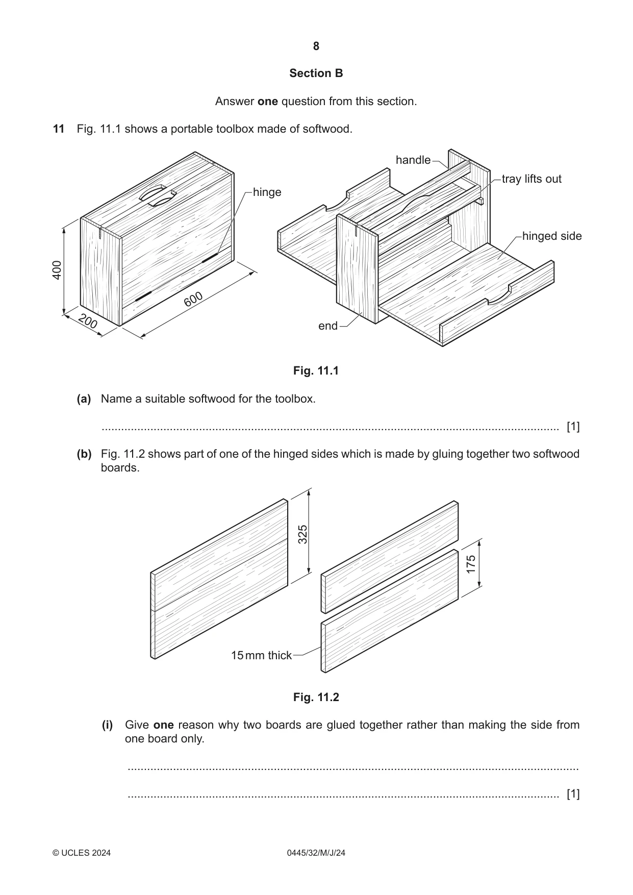
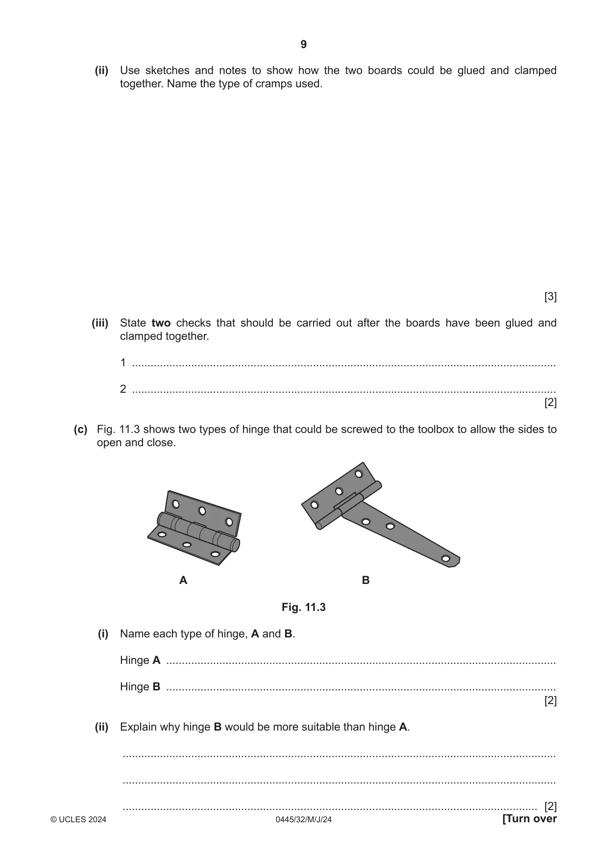
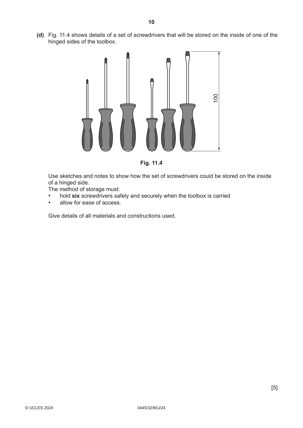
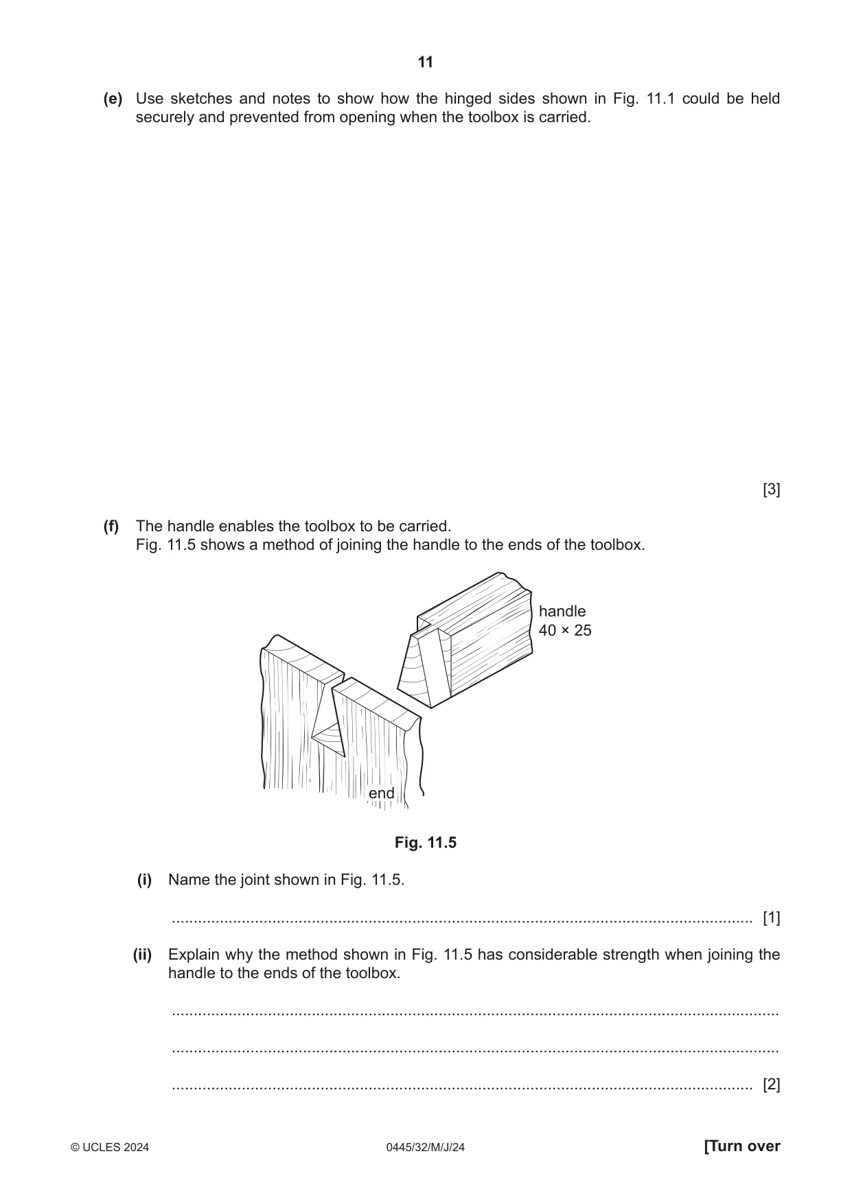
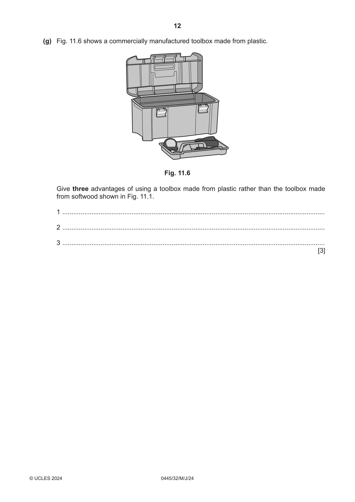
11 Fig. 11.1 shows a portable toolbox made of softwood. handle tray lifts out hinge hinged side 400 600 200 end Fig. 11.1 (a) Name a suitable softwood for the toolbox. ............................................................................................................................................. [1] (b) Fig. 11.2 shows part of one of the hinged sides which is made by gluing together two softwood boards. 325 175 15 mm thick Fig. 11.2 (i) Give one reason why two boards are glued together rather than making the side from one board only. ........................................................................................................................................... ..................................................................................................................................... [1] (ii) Use sketches and notes to show how the two boards could be glued and clamped together. Name the type of cramps used. [3] (iii) State two checks that should be carried out after the boards have been glued and clamped together. 1 ........................................................................................................................................ 2 ........................................................................................................................................ [2] (c) Fig. 11.3 shows two types of hinge that could be screwed to the toolbox to allow the sides to open and close. A B Fig. 11.3 (i) Name each type of hinge, A and B. Hinge A ............................................................................................................................. Hinge B ............................................................................................................................. [2] (ii) Explain why hinge B would be more suitable than hinge A. ........................................................................................................................................... ........................................................................................................................................... (d) Fig. 11.4 shows details of a set of screwdrivers that will be stored on the inside of one of the hinged sides of the toolbox. 100 Fig. 11.4 Use sketches and notes to show how the set of screwdrivers could be stored on the inside of a hinged side. The method of storage must: • hold six screwdrivers safely and securely when the toolbox is carried • allow for ease of access. Give details of all materials and constructions used. [5] (e) Use sketches and notes to show how the hinged sides shown in Fig. 11.1 could be held securely and prevented from opening when the toolbox is carried. [3] (f) The handle enables the toolbox to be carried. Fig. 11.5 shows a method of joining the handle to the ends of the toolbox. handle 40 × 25 end Fig. 11.5 (i) Name the joint shown in Fig. 11.5. ..................................................................................................................................... [1] (ii) Explain why the method shown in Fig. 11.5 has considerable strength when joining the handle to the ends of the toolbox. ........................................................................................................................................... ........................................................................................................................................... ..................................................................................................................................... [2] (g) Fig. 11.6 shows a commercially manufactured toolbox made from plastic. Fig. 11.6 Give three advantages of using a toolbox made from plastic rather than the toolbox made from softwood shown in Fig. 11.1. 1 ................................................................................................................................................ 2 ................................................................................................................................................ 3 ................................................................................................................................................ [3]
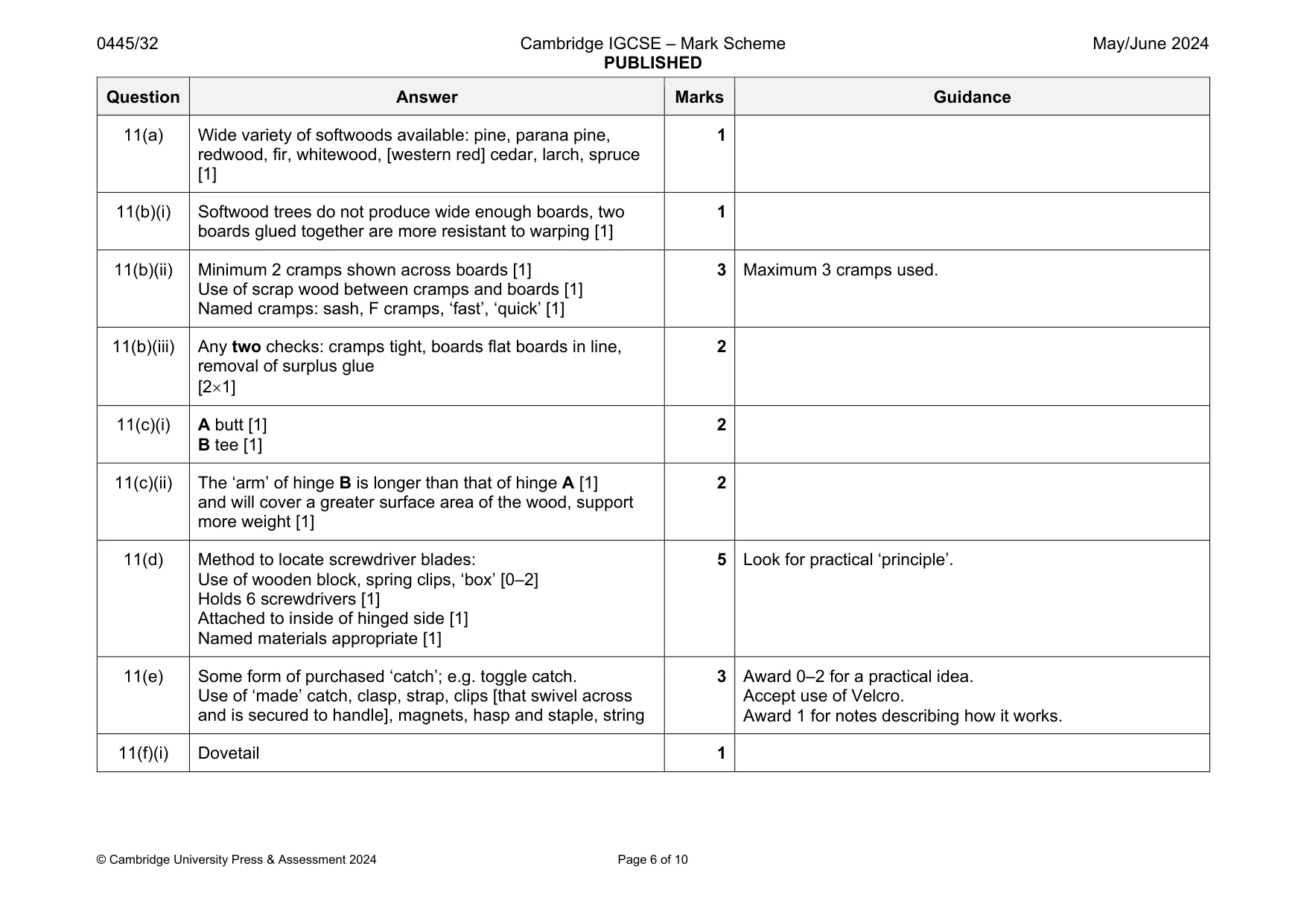
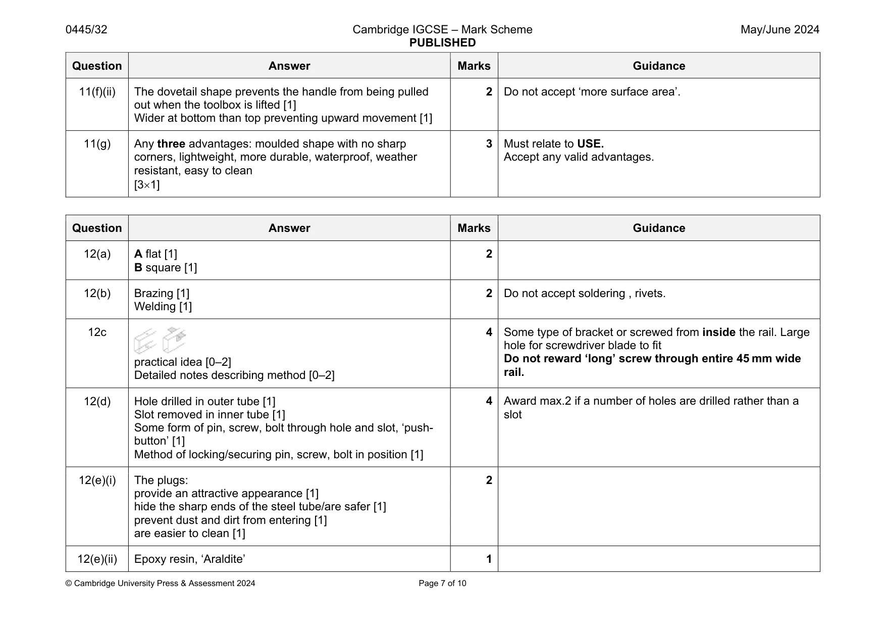
Mark scheme: 11(a) Wide variety of softwoods available: pine, parana pine, redwood, fir, whitewood, [western red] cedar, larch, spruce [1] 1 11(b)(i) Softwood trees do not produce wide enough boards, two boards glued together are more resistant to warping [1] 1 11(b)(ii) Minimum 2 cramps shown across boards [1] Use of scrap wood between cramps and boards [1] Named cramps: sash, F cramps, ‘fast’, ‘quick’ [1] 3 Maximum 3 cramps used. 11(b)(iii) Any two checks: cramps tight, boards flat boards in line, removal of surplus glue [21] 2 11(c)(i) A butt [1] B tee [1] 2 11(c)(ii) The ‘arm’ of hinge B is longer than that of hinge A [1] and will cover a greater surface area of the wood, support more weight [1] 2 11(d) Method to locate screwdriver blades: Use of wooden block, spring clips, ‘box’ [0–2] Holds 6 screwdrivers [1] Attached to inside of hinged side [1] Named materials appropriate [1] 5 Look for practical ‘principle’. 11(e) Some form of purchased ‘catch’; e.g. toggle catch. Use of ‘made’ catch, clasp, strap, clips [that swivel across and is secured to handle], magnets, hasp and staple, string 3 Award 0–2 for a practical idea. Accept use of Velcro. Award 1 for notes describing how it works. 11(f)(i) Dovetail 1 Question Answer Marks Guidance 11(f)(ii) The dovetail shape prevents the handle from being pulled out when the toolbox is lifted [1] Wider at bottom than top preventing upward movement [1] 2 Do not accept ‘more surface area’. 11(g) Any three advantages: moulded shape with no sharp corners, lightweight, more durable, waterproof, weather resistant, easy to clean [31] 3 Must relate to USE. Accept any valid advantages.
Q12 · An incomplete design for a desk that could be made in a school workshop
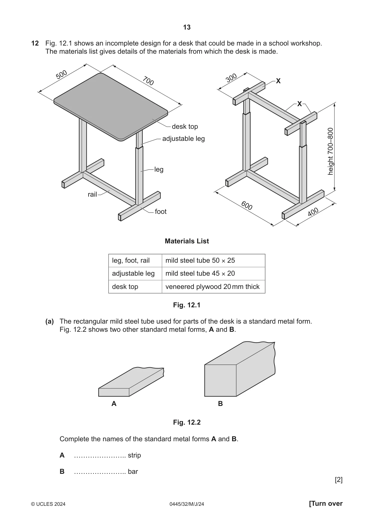
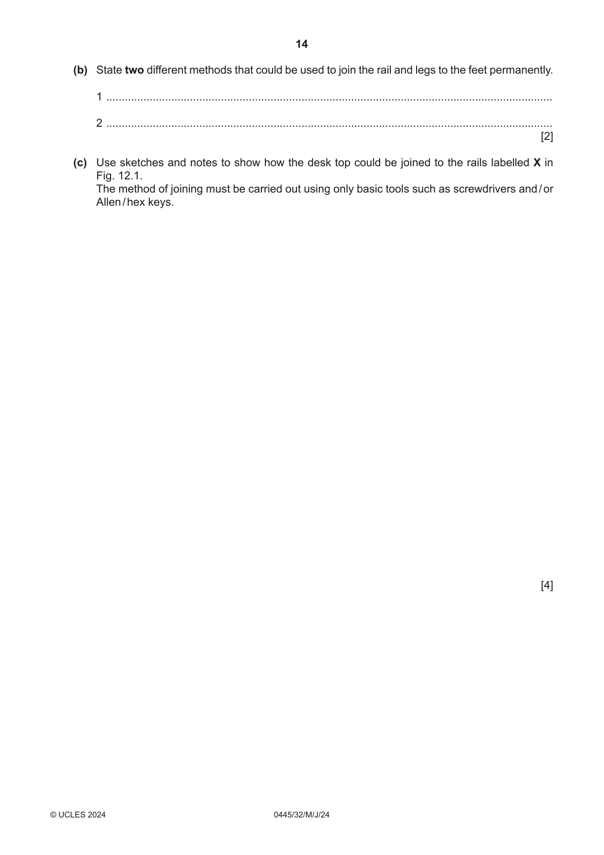
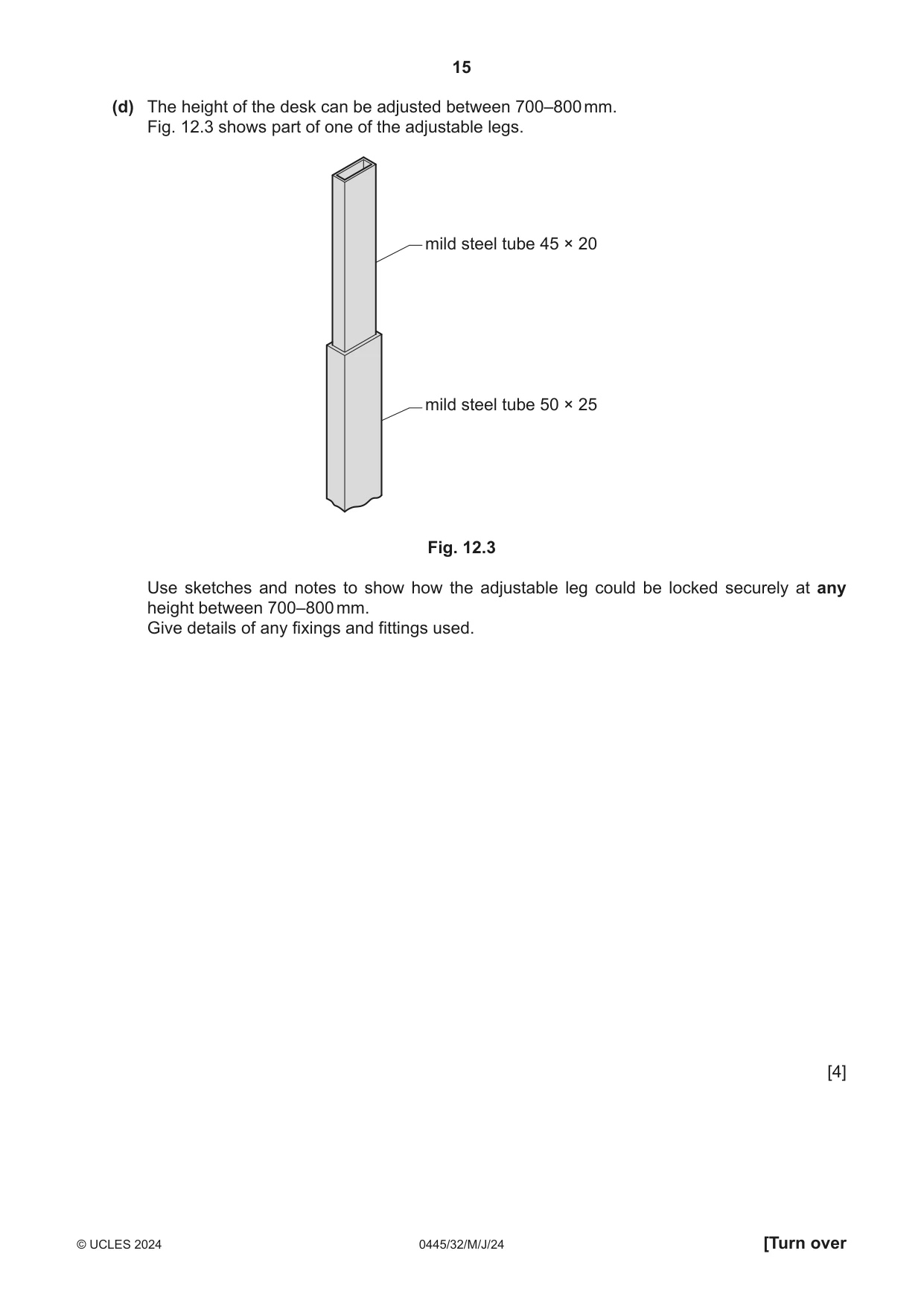
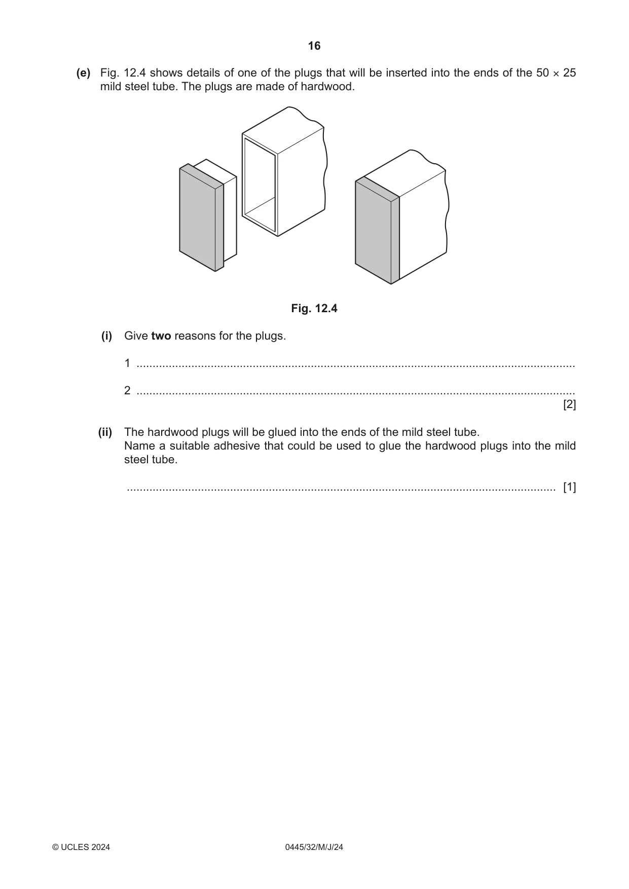
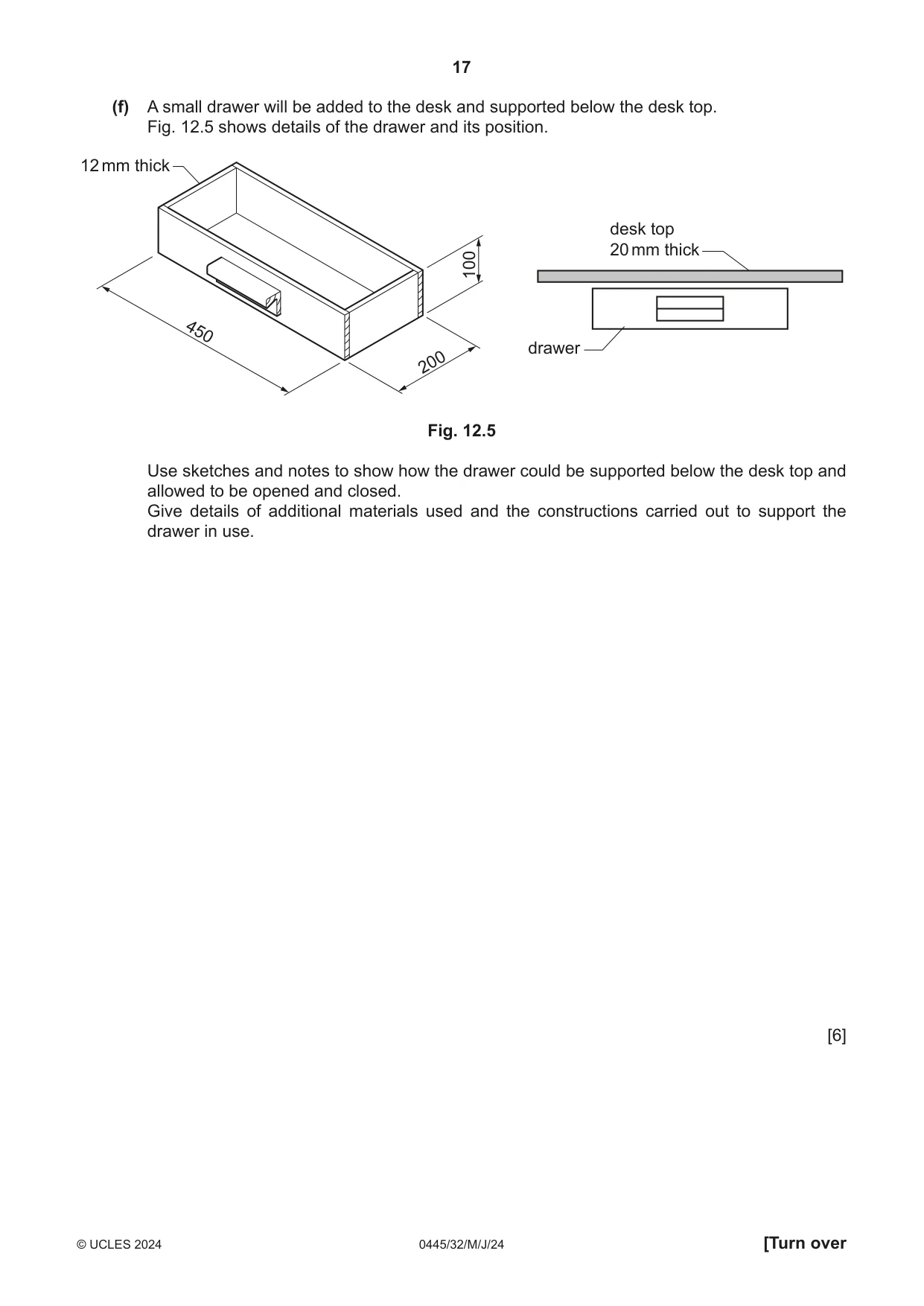
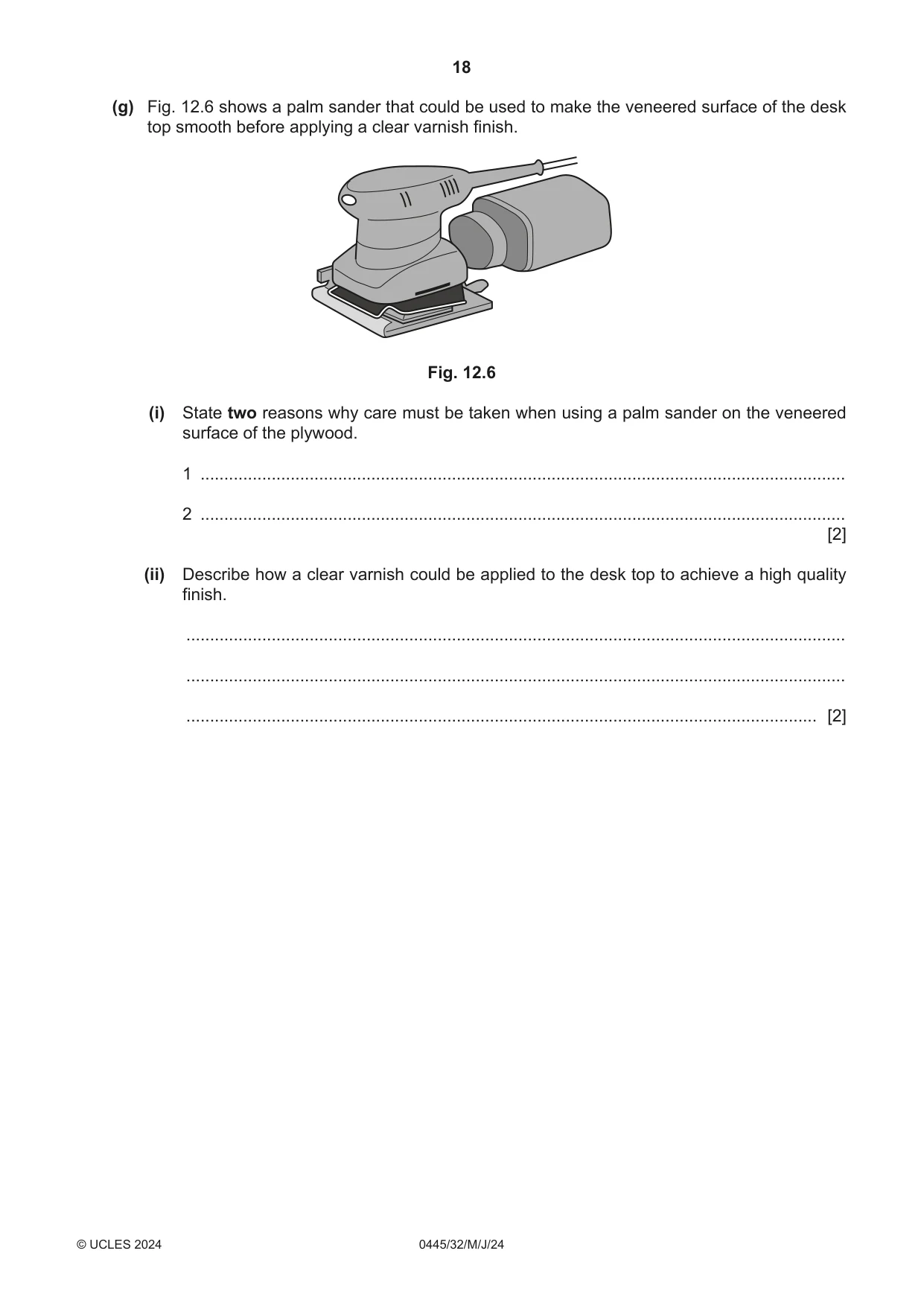
12 Fig. 12.1 shows an incomplete design for a desk that could be made in a school workshop. The materials list gives details of the materials from which the desk is made. 500 300 X 700 X desk top adjustable leg 700–800 leg height rail 600 foot 400 Materials List leg, foot, rail mild steel tube 50 × 25 adjustable leg mild steel tube 45 × 20 desk top veneered plywood 20 mm thick Fig. 12.1 (a) The rectangular mild steel tube used for parts of the desk is a standard metal form. Fig. 12.2 shows two other standard metal forms, A and B. A B Fig. 12.2 Complete the names of the standard metal forms A and B. A ………………….. strip B ………………….. bar [2] (b) State two different methods that could be used to join the rail and legs to the feet permanently. 1 ................................................................................................................................................ 2 ................................................................................................................................................ [2] (c) Use sketches and notes to show how the desk top could be joined to the rails labelled X in Fig. 12.1. The method of joining must be carried out using only basic tools such as screwdrivers and / or Allen / hex keys. [4] (d) The height of the desk can be adjusted between 700–800 mm. Fig. 12.3 shows part of one of the adjustable legs. mild steel tube 45 × 20 mild steel tube 50 × 25 Fig. 12.3 Use sketches and notes to show how the adjustable leg could be locked securely at any height between 700–800 mm. Give details of any fixings and fittings used. [4] (e) Fig. 12.4 shows details of one of the plugs that will be inserted into the ends of the 50 × 25 mild steel tube. The plugs are made of hardwood. Fig. 12.4 (i) Give two reasons for the plugs. 1 ........................................................................................................................................ 2 ........................................................................................................................................ [2] (ii) The hardwood plugs will be glued into the ends of the mild steel tube. Name a suitable adhesive that could be used to glue the hardwood plugs into the mild steel tube. ..................................................................................................................................... [1] (f) A small drawer will be added to the desk and supported below the desk top. Fig. 12.5 shows details of the drawer and its position. 12 mm thick desk top 20 mm thick 100 450 drawer 200 Fig. 12.5 Use sketches and notes to show how the drawer could be supported below the desk top and allowed to be opened and closed. Give details of additional materials used and the constructions carried out to support the drawer in use. [6] (g) Fig. 12.6 shows a palm sander that could be used to make the veneered surface of the desk top smooth before applying a clear varnish finish. Fig. 12.6 (i) State two reasons why care must be taken when using a palm sander on the veneered surface of the plywood. 1 ........................................................................................................................................ 2 ........................................................................................................................................ [2] (ii) Describe how a clear varnish could be applied to the desk top to achieve a high quality finish. ........................................................................................................................................... ........................................................................................................................................... ..................................................................................................................................... [2]
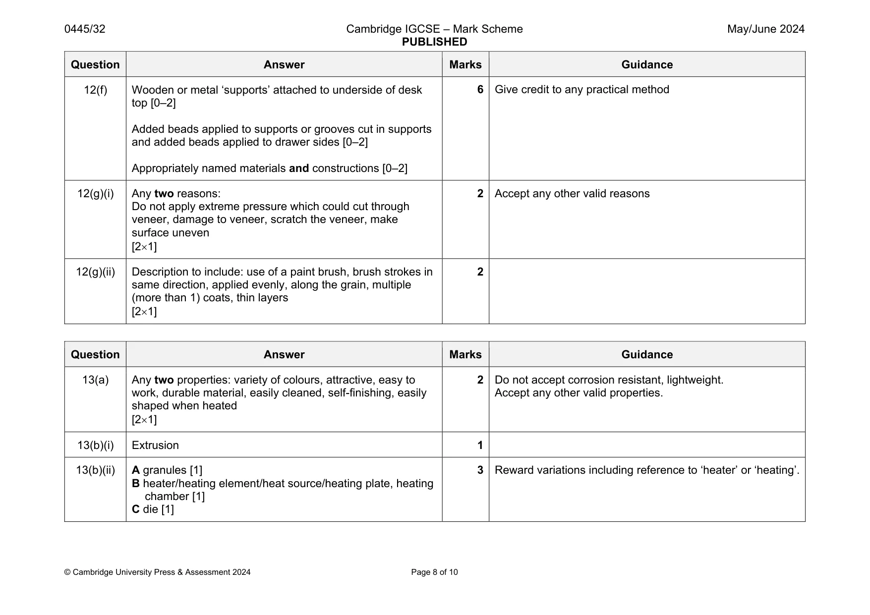
Mark scheme: 12(a) A flat [1] B square [1] 12(b) Brazing [1] Welding [1] 2 Do not accept soldering , rivets. 12c practical idea [0–2] Detailed notes describing method [0–2] 4 Some type of bracket or screwed from inside the rail. Large hole for screwdriver blade to fit Do not reward ‘long’ screw through entire 45 mm wide rail. 12(d) Hole drilled in outer tube [1] Slot removed in inner tube [1] Some form of pin, screw, bolt through hole and slot, ‘push- button’ [1] Method of locking/securing pin, screw, bolt in position [1] 4 Award max.2 if a number of holes are drilled rather than a slot 12(e)(i) The plugs: provide an attractive appearance [1] hide the sharp ends of the steel tube/are safer [1] prevent dust and dirt from entering [1] are easier to clean [1] 2 12(e)(ii) Epoxy resin, ‘Araldite’ 1 Question Answer Marks Guidance 12(f) Wooden or metal ‘supports’ attached to underside of desk top [0–2] Added beads applied to supports or grooves cut in supports and added beads applied to drawer sides [0–2] Appropriately named materials and constructions [0–2] 6 Give credit to any practical method 12(g)(i) Any two reasons: Do not apply extreme pressure which could cut through veneer, damage to veneer, scratch the veneer, make surface uneven [21] 2 Accept any other valid reasons 12(g)(ii) Description to include: use of a paint brush, brush strokes in same direction, applied evenly, along the grain, multiple (more than 1) coats, thin layers [21] 2
Q13 · Views of a desk tidy that will be batch produced in a school workshop
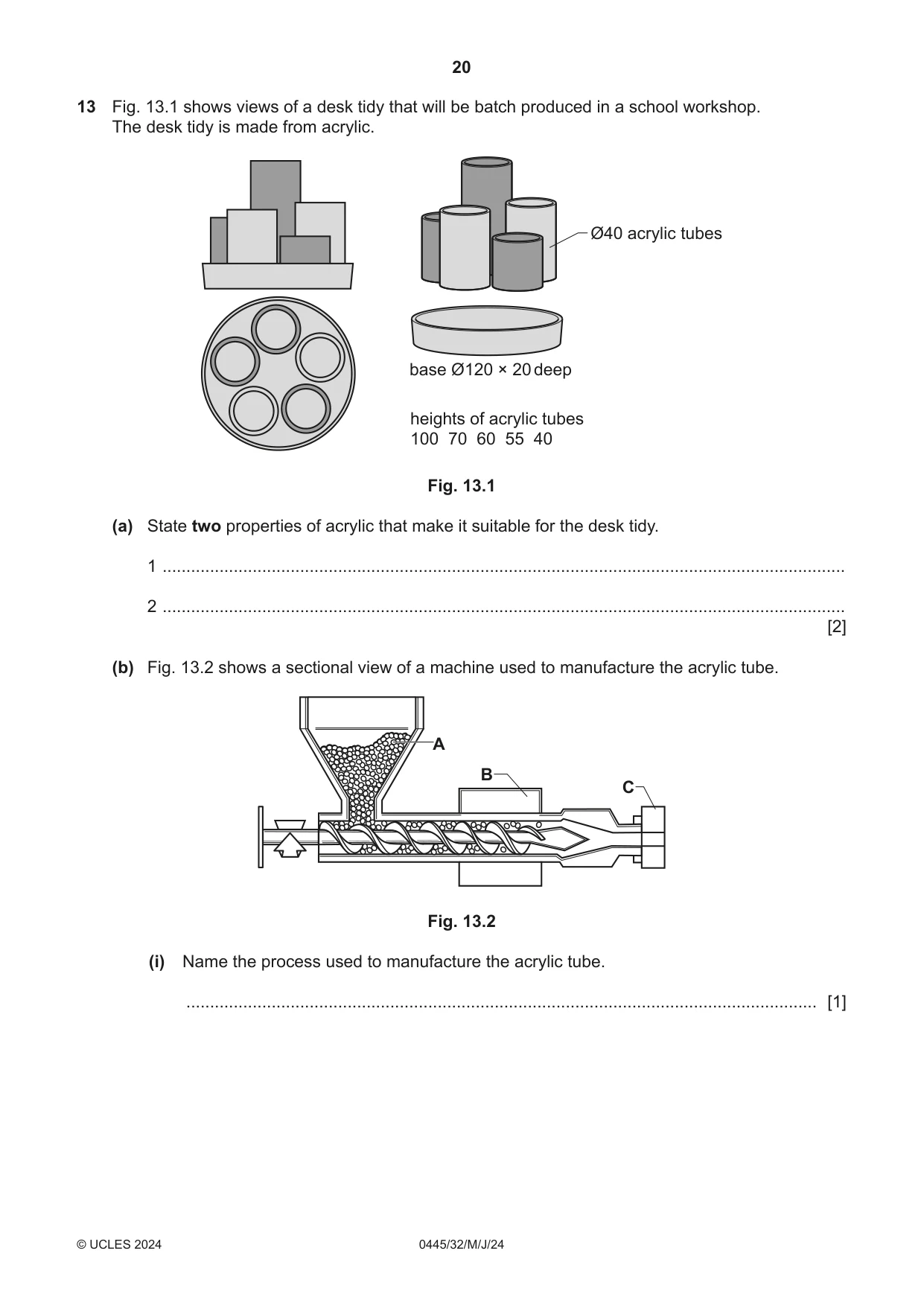
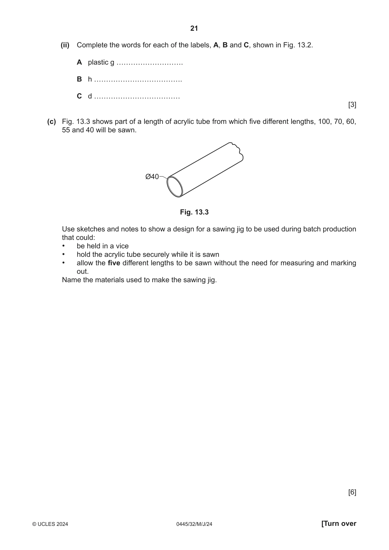
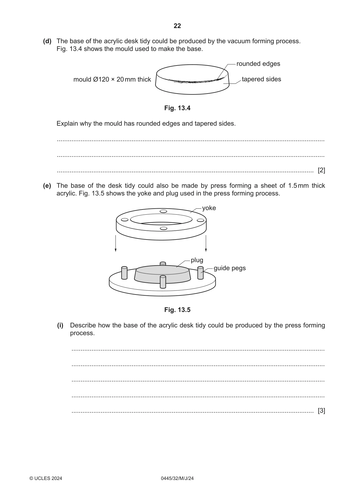
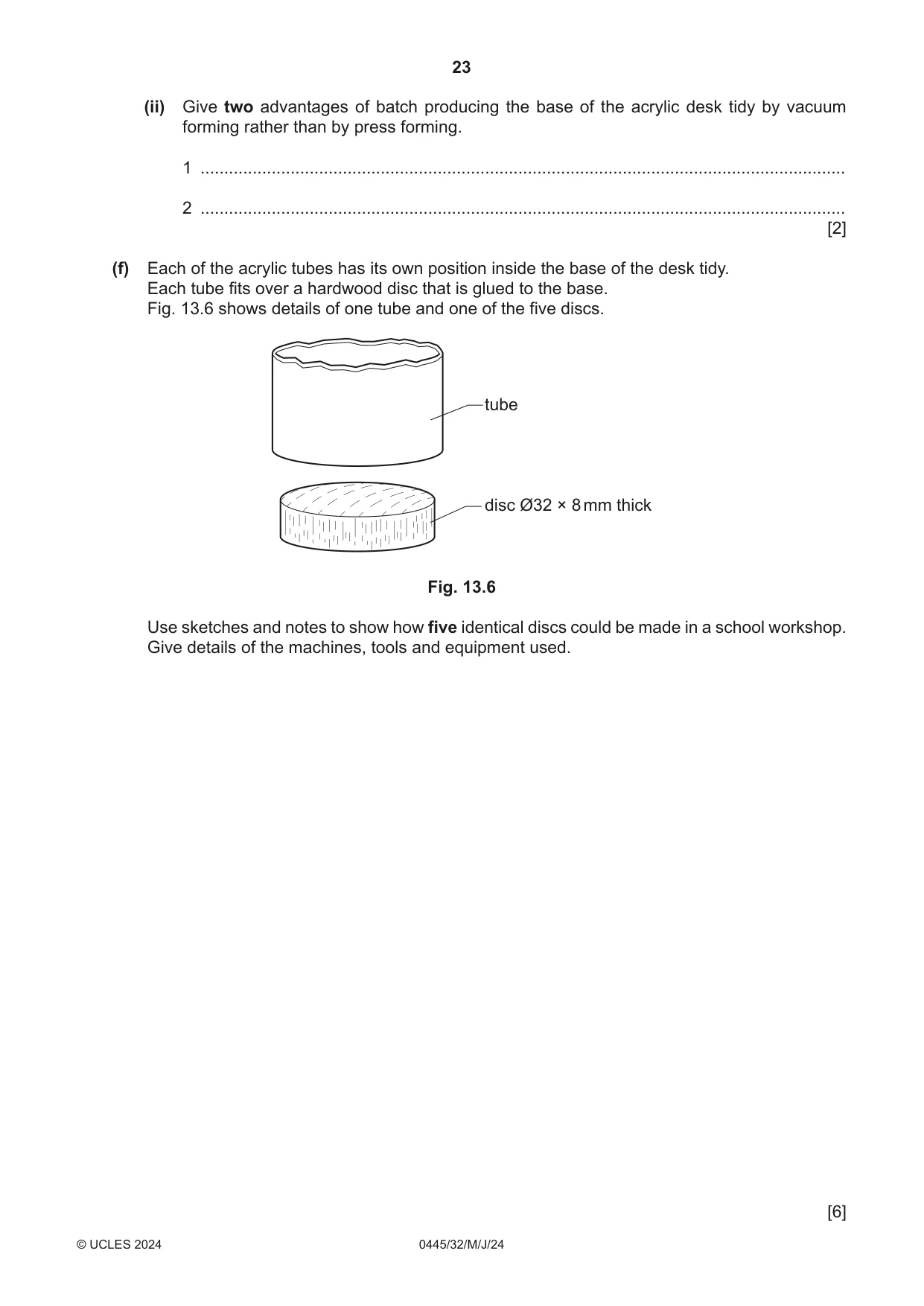
13 Fig. 13.1 shows views of a desk tidy that will be batch produced in a school workshop. The desk tidy is made from acrylic. Ø40 acrylic tubes base Ø120 × 20 deep heights of acrylic tubes 100 70 60 55 40 Fig. 13.1 (a) State two properties of acrylic that make it suitable for the desk tidy. 1 ................................................................................................................................................ 2 ................................................................................................................................................ [2] (b) Fig. 13.2 shows a sectional view of a machine used to manufacture the acrylic tube. A B C Fig. 13.2 (i) Name the process used to manufacture the acrylic tube. ..................................................................................................................................... [1] (ii) Complete the words for each of the labels, A, B and C, shown in Fig. 13.2. A plastic g ………………………. B h ………………………………. C d ……………………………… [3] (c) Fig. 13.3 shows part of a length of acrylic tube from which five different lengths, 100, 70, 60, 55 and 40 will be sawn. Ø40 Fig. 13.3 Use sketches and notes to show a design for a sawing jig to be used during batch production that could: • be held in a vice • hold the acrylic tube securely while it is sawn • allow the five different lengths to be sawn without the need for measuring and marking out. Name the materials used to make the sawing jig. [6] (d) The base of the acrylic desk tidy could be produced by the vacuum forming process. Fig. 13.4 shows the mould used to make the base. rounded edges mould Ø120 × 20 mm thick tapered sides Fig. 13.4 Explain why the mould has rounded edges and tapered sides. ................................................................................................................................................... ................................................................................................................................................... ............................................................................................................................................. [2] (e) The base of the desk tidy could also be made by press forming a sheet of 1.5 mm thick acrylic. Fig. 13.5 shows the yoke and plug used in the press forming process. yoke plug guide pegs Fig. 13.5 (i) Describe how the base of the acrylic desk tidy could be produced by the press forming process. ........................................................................................................................................... ........................................................................................................................................... ........................................................................................................................................... ........................................................................................................................................... ..................................................................................................................................... [3]
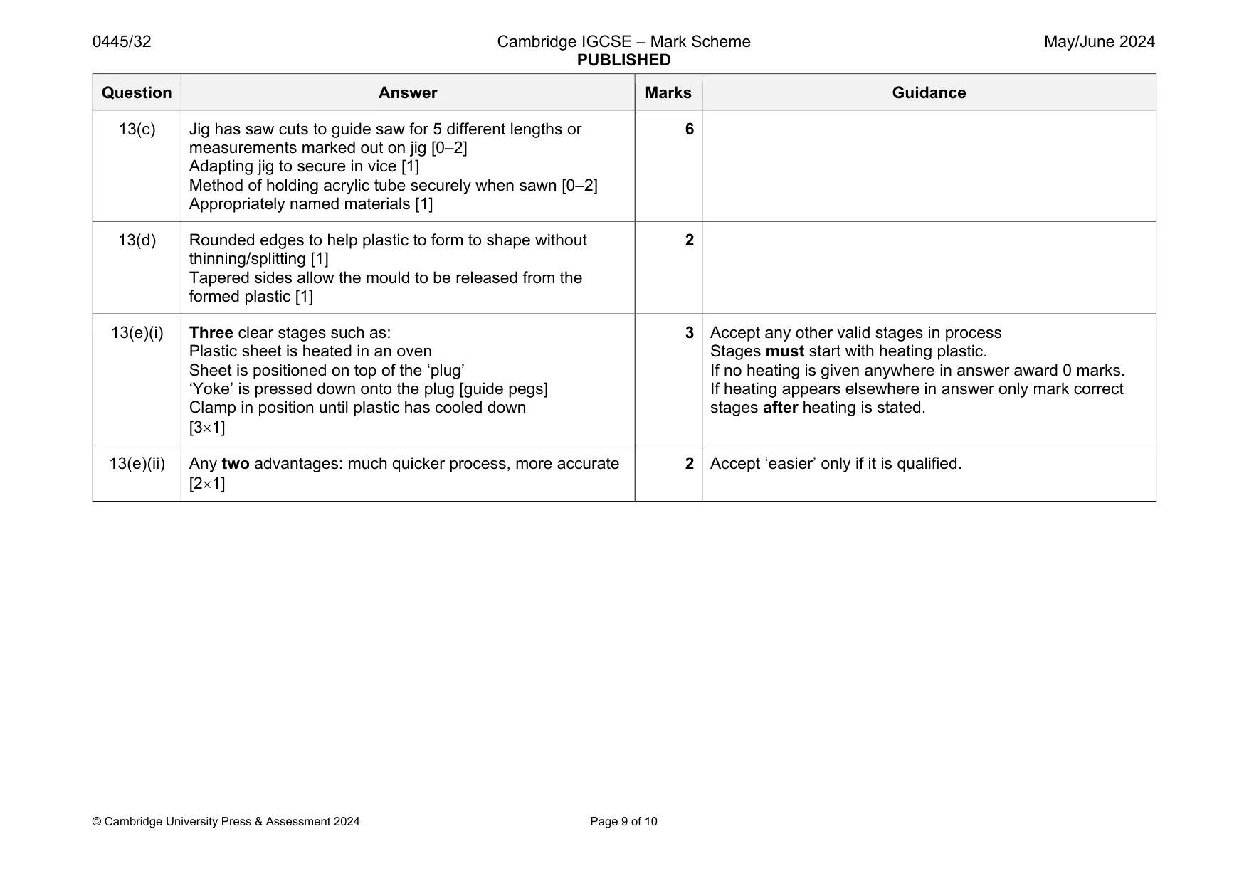
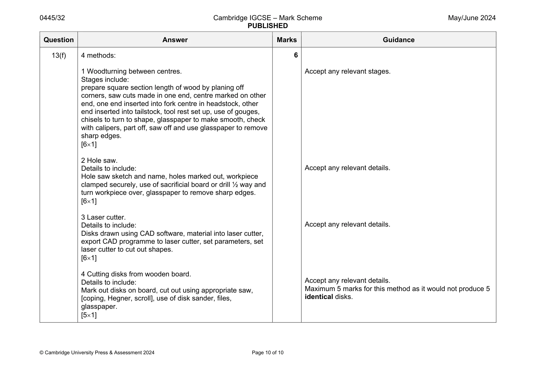
Mark scheme: 13(a) Any two properties: variety of colours, attractive, easy to work, durable material, easily cleaned, self-finishing, easily shaped when heated [21] 2 Do not accept corrosion resistant, lightweight. Accept any other valid properties. 13(b)(i) Extrusion 1 13(b)(ii) A granules [1] B heater/heating element/heat source/heating plate, heating chamber [1] C die [1] 3 Reward variations including reference to ‘heater’ or ‘heating’. Question Answer Marks Guidance 13(c) Jig has saw cuts to guide saw for 5 different lengths or measurements marked out on jig [0–2] Adapting jig to secure in vice [1] Method of holding acrylic tube securely when sawn [0–2] Appropriately named materials [1] 6 13(d) Rounded edges to help plastic to form to shape without thinning/splitting [1] Tapered sides allow the mould to be released from the formed plastic [1] 2 13(e)(i) Three clear stages such as: Plastic sheet is heated in an oven Sheet is positioned on top of the ‘plug’ ‘Yoke’ is pressed down onto the plug [guide pegs] Clamp in position until plastic has cooled down [31] 3 Accept any other valid stages in process Stages must start with heating plastic. If no heating is given anywhere in answer award 0 marks. If heating appears elsewhere in answer only mark correct stages after heating is stated. 13(e)(ii) Any two advantages: much quicker process, more accurate [21] 2 Accept ‘easier’ only if it is qualified. Question Answer Marks Guidance 13(f) 4 methods: 1 Woodturning between centres. Stages include: prepare square section length of wood by planing off corners, saw cuts made in one end, centre marked on other end, one end inserted into fork centre in headstock, other end inserted into tailstock, tool rest set up, use of gouges, chisels to turn to shape, glasspaper to make smooth, check with calipers, part off, saw off and use glasspaper to remove sharp edges. [61] 2 Hole saw. Details to include: Hole saw sketch and name, holes marked out, workpiece clamped securely, use of sacrificial board or drill ½ way and turn workpiece over, glasspaper to remove sharp edges. [61] 3 Laser cutter. Details to include: Disks drawn using CAD software, material into laser cutter, export CAD programme to laser cutter, set parameters, set laser cutter to cut out shapes. [61] 4 Cutting disks from wooden board. Details to include: Mark out disks on board, cut out using appropriate saw, [coping, Hegner, scroll], use of disk sander, files, glasspaper. [51] 6 Accept any relevant stages. Accept any relevant details. Accept any relevant details. Accept any relevant details. Maximum 5 marks for this method as it would not produce 5 identical disks.
What was in this paper
The subtopics covered by these 13 questions, and how many questions each got. Open one in a new tab to see every Cambridge question on it.
What you needed in this session
Cambridge’s own grade thresholds for 2024 May/June, Paper 3 · Variant 2. A higher threshold means an easier paper — the bar moves with how the cohort did.