Cambridge IGCSE Design and Technology 0445 — 2023 May/June Paper 3 · Variant 2
0445/32/M/J/23 · 13 questions · 50 marks · ≈56 min
The question paper and its mark scheme, free to read here and free to download. This is Cambridge’s own paper, exactly as it was sat.
Question paper20 pages
Mark scheme9 pages
Answers below. Sit the paper first if you are practising.
Questions as text
Q1 · A variety of television remote controls
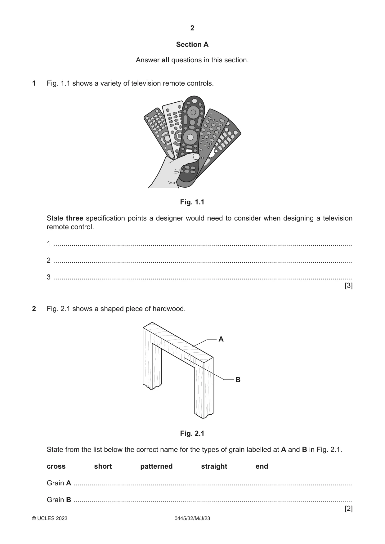
1 Fig. 1.1 shows a variety of television remote controls. Fig. 1.1 State three specification points a designer would need to consider when designing a television remote control. 1 ....................................................................................................................................................... 2 ....................................................................................................................................................... 3 ....................................................................................................................................................... [3]
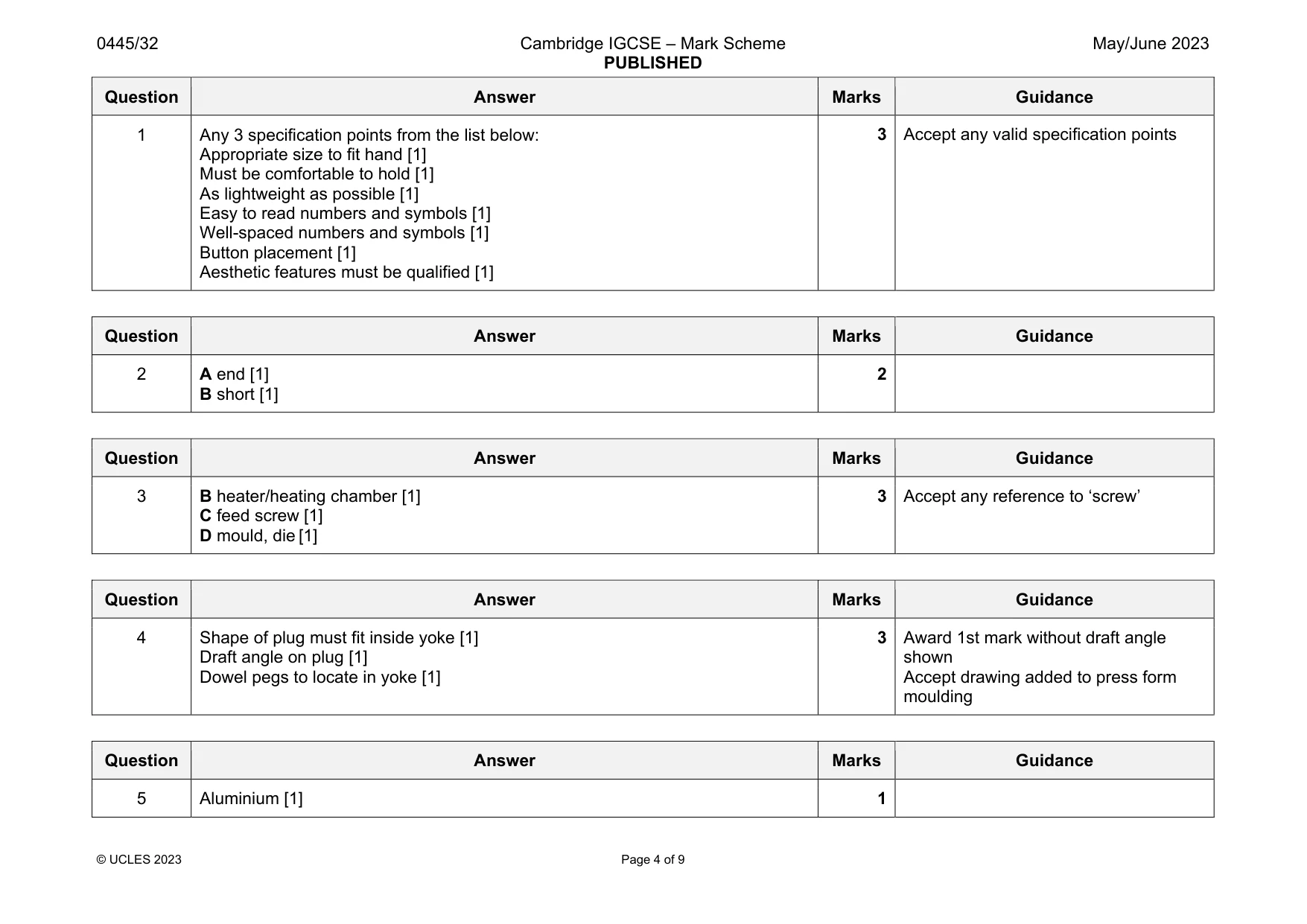
Mark scheme: 1 Any 3 specification points from the list below: Appropriate size to fit hand [1] Must be comfortable to hold [1] As lightweight as possible [1] Easy to read numbers and symbols [1] Well-spaced numbers and symbols [1] Button placement [1] Aesthetic features must be qualified [1]
Q2 · A shaped piece of hardwood
2 Fig. 2.1 shows a shaped piece of hardwood. A B Fig. 2.1 State from the list below the correct name for the types of grain labelled at A and B in Fig. 2.1. cross short patterned straight end Grain A ............................................................................................................................................. Grain B ............................................................................................................................................. [2]
Mark scheme: 2 A end [1] B short [1]
Q3 · A cross-sectional view of an injection moulding machine
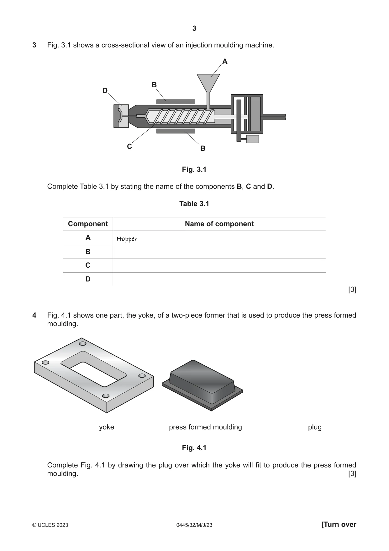
3 Fig. 3.1 shows a cross-sectional view of an injection moulding machine. A B D C B Fig. 3.1 Complete Table 3.1 by stating the name of the components B, C and D. Table 3.1 Component Name of component A Hopper B C D [3]
Mark scheme: 3 B heater/heating chamber [1] C feed screw [1] D mould, die [1] 3 Accept any reference to ‘screw’
Q4 · One part, the yoke, of a two-piece former that is used to produce the press formed…
4 Fig. 4.1 shows one part, the yoke, of a two-piece former that is used to produce the press formed moulding. yoke press formed moulding plug Fig. 4.1 Complete Fig. 4.1 by drawing the plug over which the yoke will fit to produce the press formed moulding. [3]
Mark scheme: 4 Shape of plug must fit inside yoke [1] Draft angle on plug [1] Dowel pegs to locate in yoke [1] 3 Award 1st mark without draft angle shown Accept drawing added to press form moulding
Q5 · Circle from the list below one metal that is a pure metal
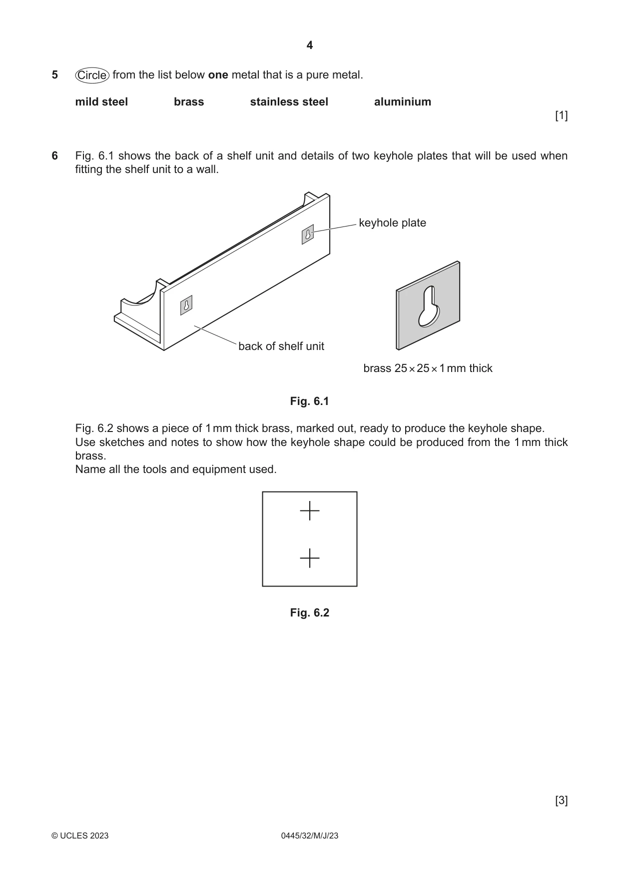
5 Circle from the list below one metal that is a pure metal. mild steel brass stainless steel aluminium [1]
Mark scheme: 5 Aluminium [1] 1
Q6 · The back of a shelf unit and details of two keyhole plates that will be used when fitting…
6 Fig. 6.1 shows the back of a shelf unit and details of two keyhole plates that will be used when fitting the shelf unit to a wall. keyhole plate back of shelf unit brass 25 × 25 × 1 mm thick Fig. 6.1 Fig. 6.2 shows a piece of 1 mm thick brass, marked out, ready to produce the keyhole shape. Use sketches and notes to show how the keyhole shape could be produced from the 1 mm thick brass. Name all the tools and equipment used. Fig. 6.2 [3]
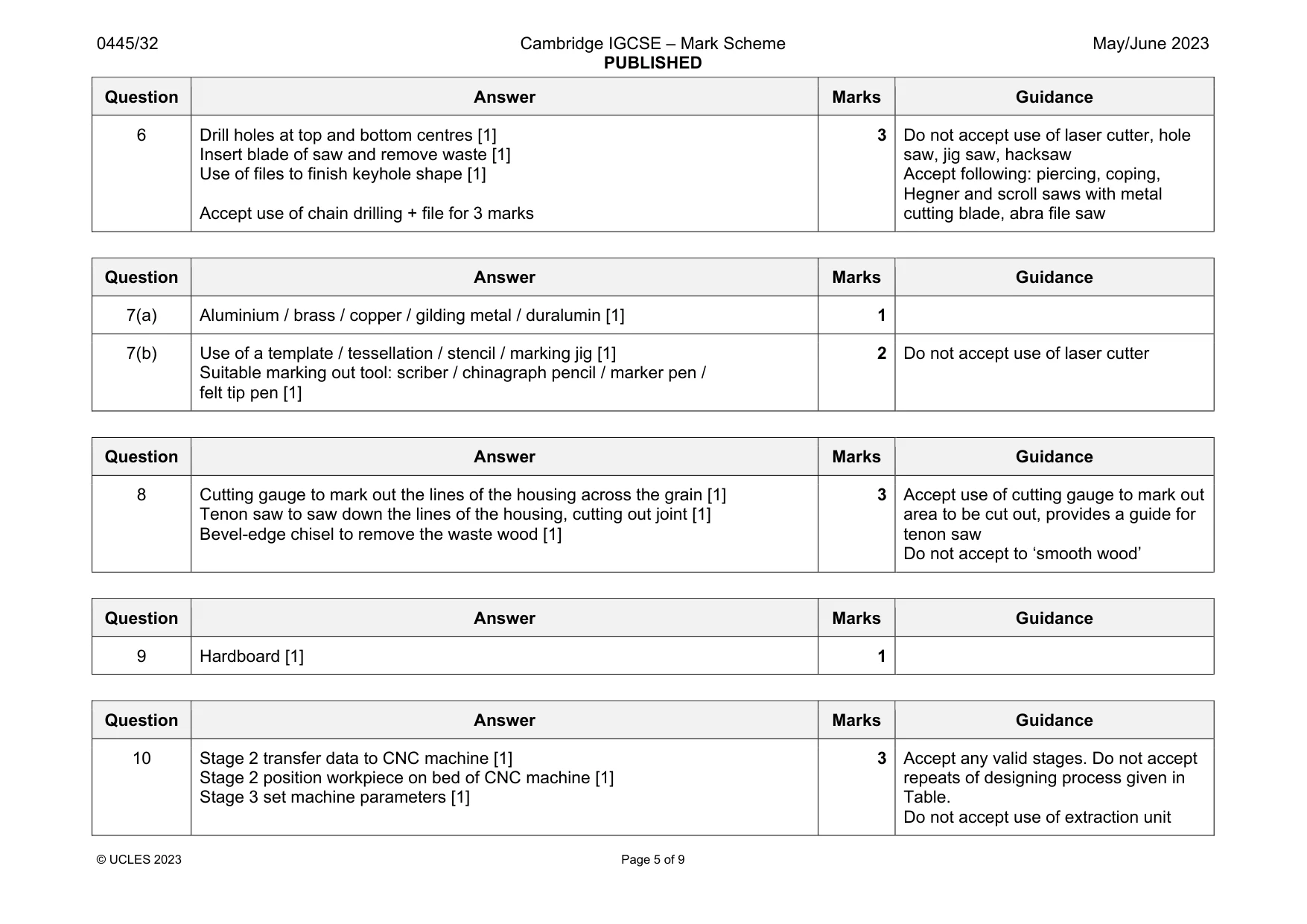
Mark scheme: 6 Drill holes at top and bottom centres [1] Insert blade of saw and remove waste [1] Use of files to finish keyhole shape [1] Accept use of chain drilling + file for 3 marks 3 Do not accept use of laser cutter, hole saw, jig saw, hacksaw Accept following: piercing, coping, Hegner and scroll saws with metal cutting blade, abra file saw
Q7 · A table number stand used in a cafe and a development (net) of the stand
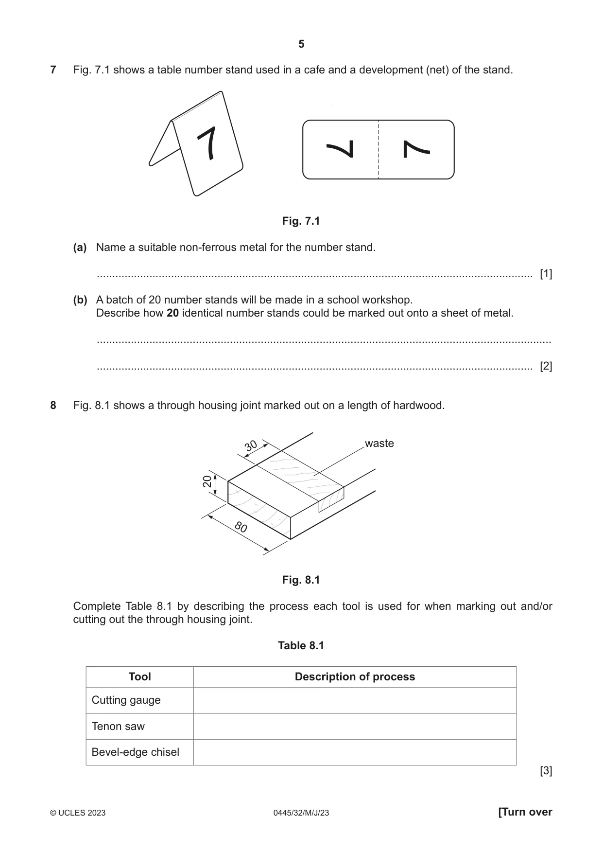
7 Fig. 7.1 shows a table number stand used in a cafe and a development (net) of the stand. 7 7 7 Fig. 7.1 (a) Name a suitable non-ferrous metal for the number stand. ............................................................................................................................................. [1] (b) A batch of 20 number stands will be made in a school workshop. Describe how 20 identical number stands could be marked out onto a sheet of metal. ................................................................................................................................................... ............................................................................................................................................. [2]
Mark scheme: 7(a) Aluminium / brass / copper / gilding metal / duralumin [1] 1 7(b) Use of a template / tessellation / stencil / marking jig [1] Suitable marking out tool: scriber / chinagraph pencil / marker pen / felt tip pen [1] 2 Do not accept use of laser cutter
Q8 · A through housing joint marked out on a length of hardwood
8 Fig. 8.1 shows a through housing joint marked out on a length of hardwood. 30 waste 20 80 Fig. 8.1 Complete Table 8.1 by describing the process each tool is used for when marking out and/or cutting out the through housing joint. Table 8.1 Tool Description of process Cutting gauge Tenon saw Bevel-edge chisel [3]
Mark scheme: 8 Cutting gauge to mark out the lines of the housing across the grain [1] Tenon saw to saw down the lines of the housing, cutting out joint [1] Bevel-edge chisel to remove the waste wood [1] 3 Accept use of cutting gauge to mark out area to be cut out, provides a guide for tenon saw Do not accept to ‘smooth wood’
Q9 · Circle from the list below one material that is biodegradable
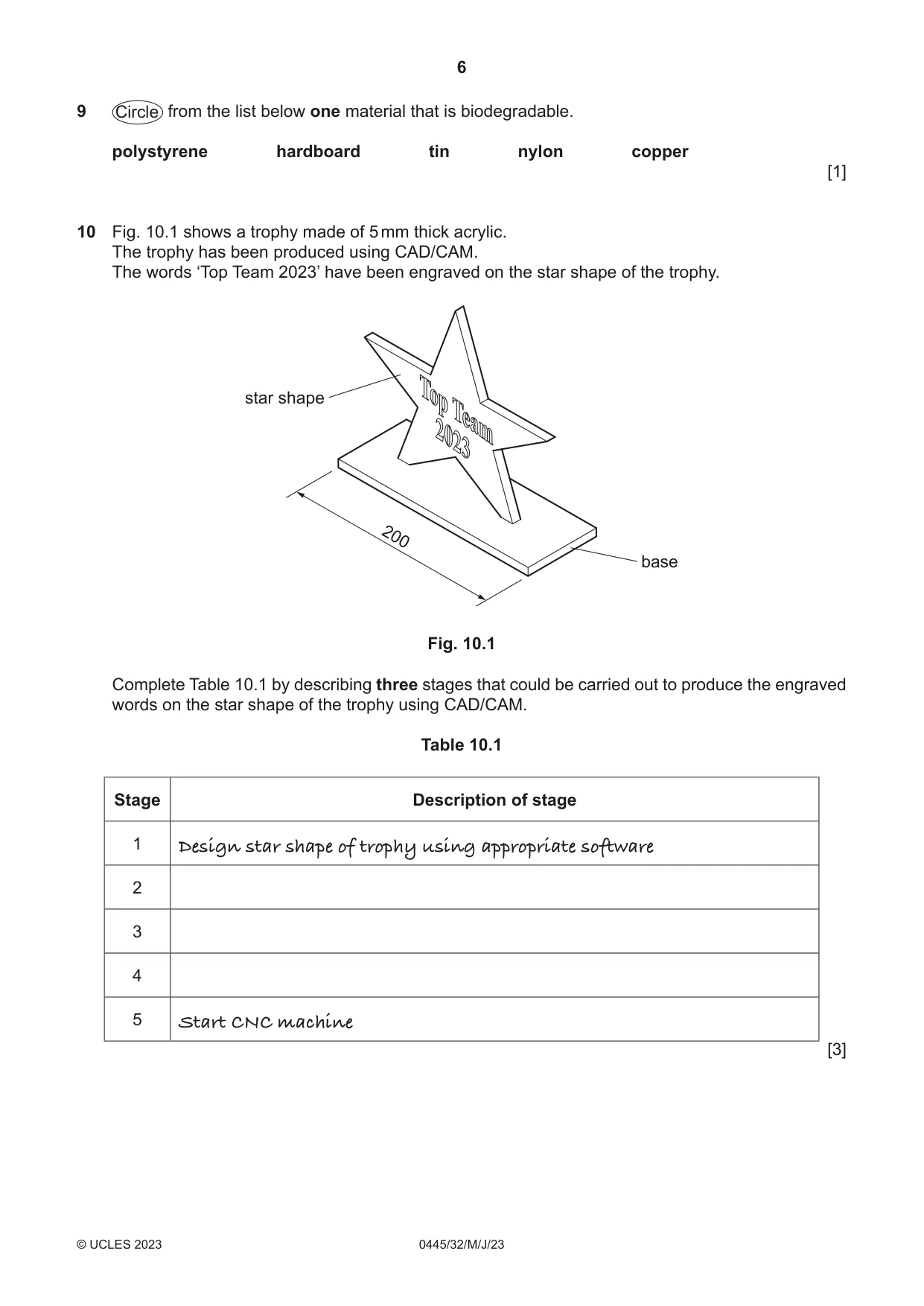
9 Circle from the list below one material that is biodegradable. polystyrene hardboard tin nylon copper [1]
Mark scheme: 9 Hardboard [1] 1
Q10 · A trophy made of 5 mm thick acrylic
10 Fig. 10.1 shows a trophy made of 5 mm thick acrylic. The trophy has been produced using CAD/CAM. The words ‘Top Team 2023’ have been engraved on the star shape of the trophy. star shape 200 base Fig. 10.1 Complete Table 10.1 by describing three stages that could be carried out to produce the engraved words on the star shape of the trophy using CAD/CAM. Table 10.1 Stage Description of stage 1 Design star shape of trophy using appropriate software 2 3 4 5 Start CNC machine [3]
Mark scheme: 10 Stage 2 transfer data to CNC machine [1] Stage 2 position workpiece on bed of CNC machine [1] Stage 3 set machine parameters [1] 3 Accept any valid stages. Do not accept repeats of designing process given in Table. Do not accept use of extraction unit
Q11 · An incomplete design for a guitar stand
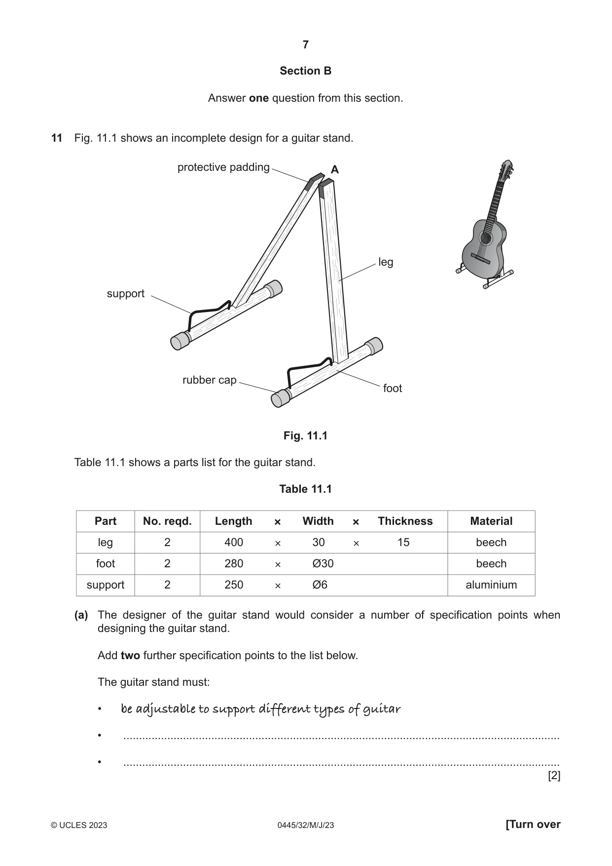
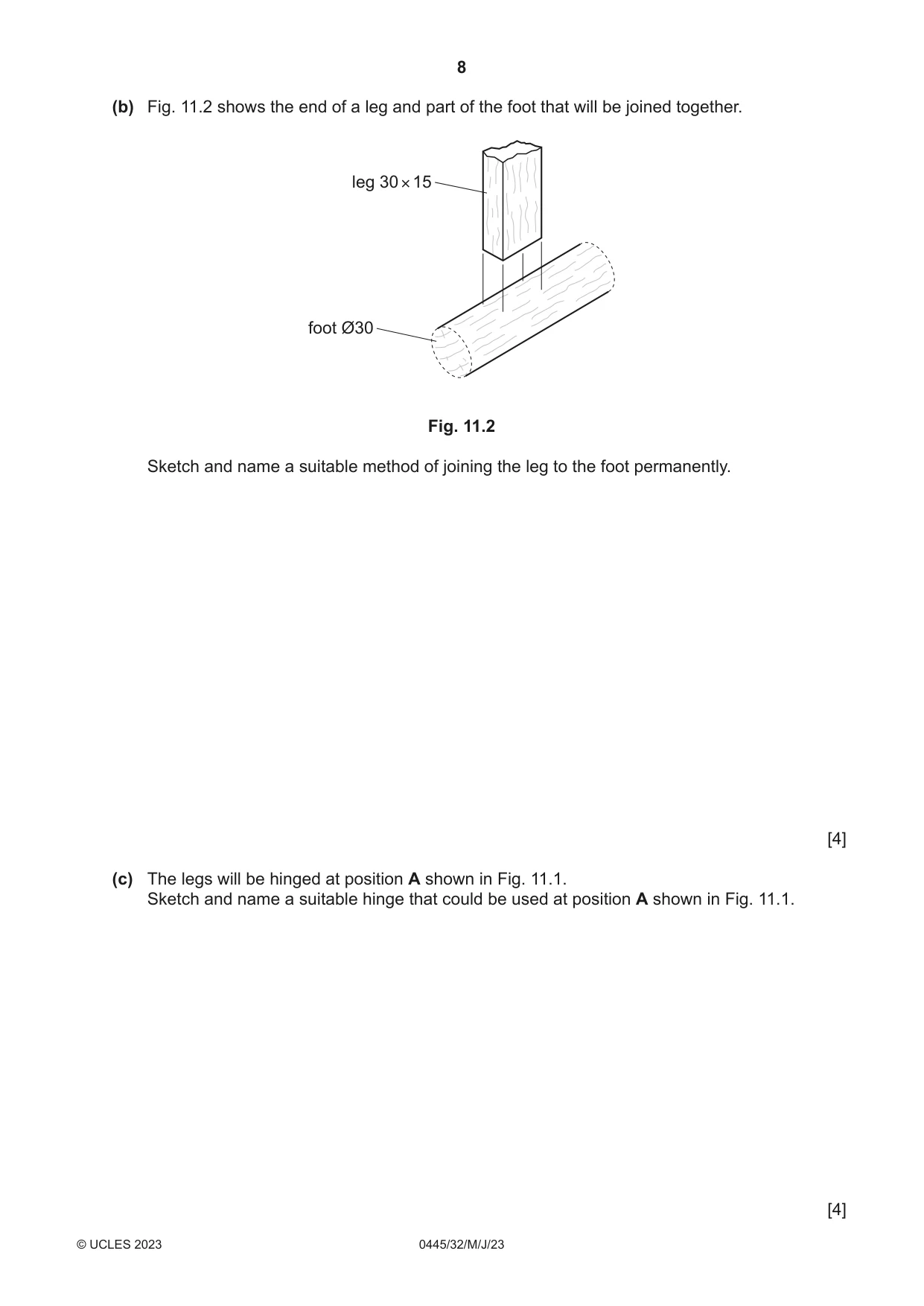
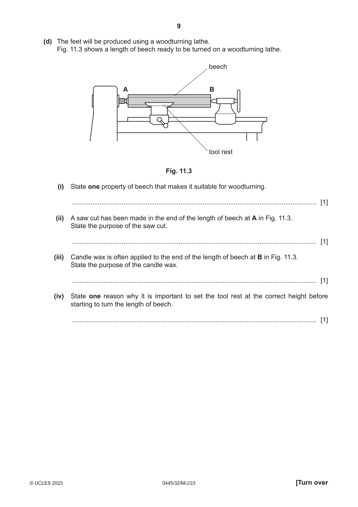
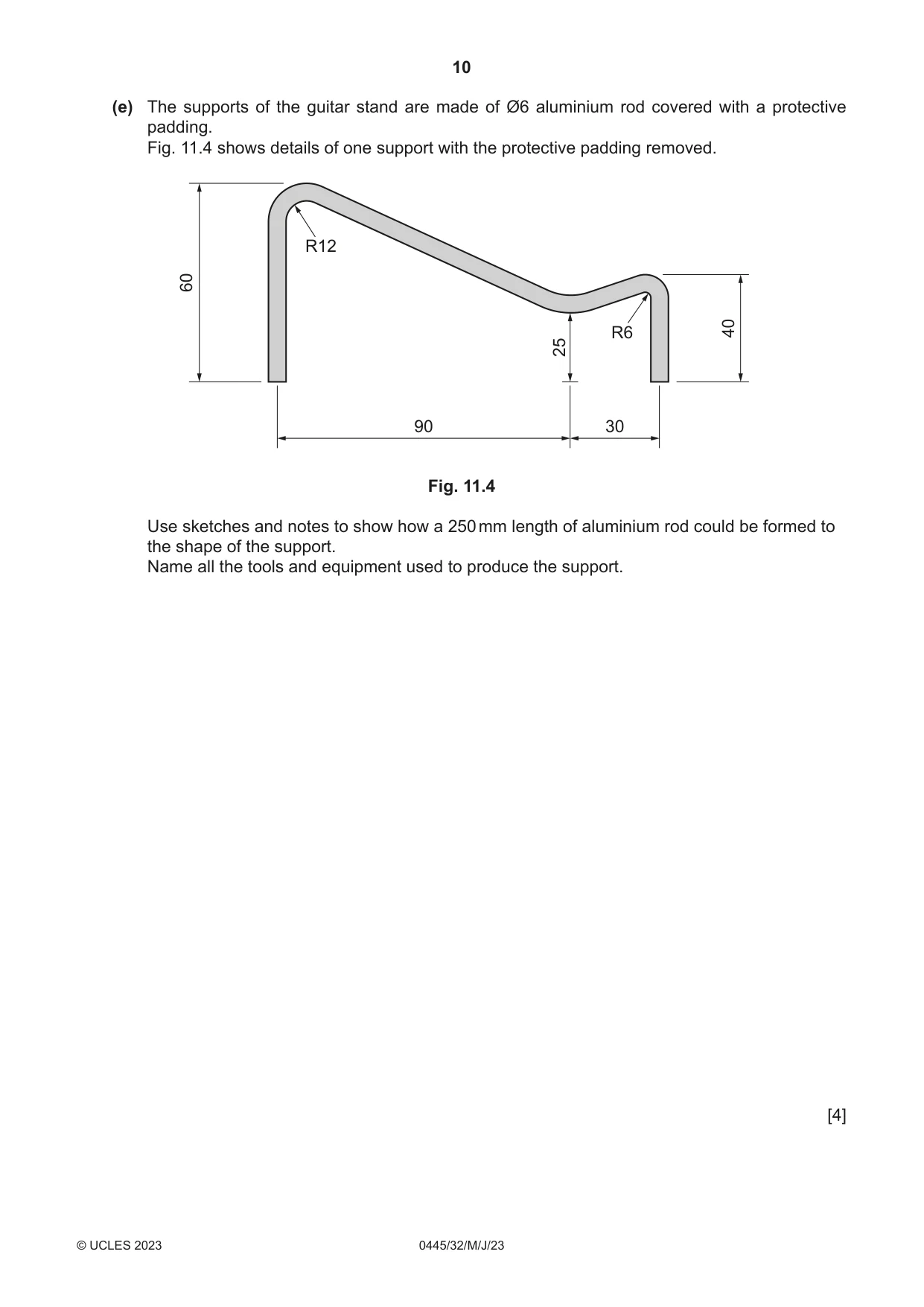
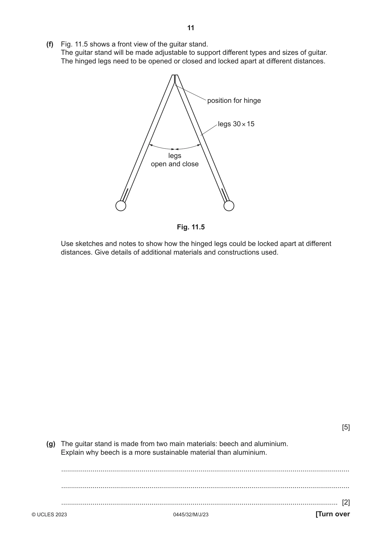
11 Fig. 11.1 shows an incomplete design for a guitar stand. protective padding A leg support rubber cap foot Fig. 11.1 Table 11.1 shows a parts list for the guitar stand. Table 11.1 Part No. reqd. Length × Width × Thickness Material leg 2 400 × 30 × 15 beech foot 2 280 × Ø30 beech support 2 250 × Ø6 aluminium (a) The designer of the guitar stand would consider a number of specification points when designing the guitar stand. Add two further specification points to the list below. The guitar stand must: • be adjustable to support different types of guitar • ........................................................................................................................................... • ........................................................................................................................................... [2] (b) Fig. 11.2 shows the end of a leg and part of the foot that will be joined together. leg 30 × 15 foot Ø30 Fig. 11.2 Sketch and name a suitable method of joining the leg to the foot permanently. [4] (c) The legs will be hinged at position A shown in Fig. 11.1. Sketch and name a suitable hinge that could be used at position A shown in Fig. 11.1. [4] (d) The feet will be produced using a woodturning lathe. Fig. 11.3 shows a length of beech ready to be turned on a woodturning lathe. beech A B tool rest Fig. 11.3 (i) State one property of beech that makes it suitable for woodturning. ..................................................................................................................................... [1] (ii) A saw cut has been made in the end of the length of beech at A in Fig. 11.3. State the purpose of the saw cut. ..................................................................................................................................... [1] (iii) Candle wax is often applied to the end of the length of beech at B in Fig. 11.3. State the purpose of the candle wax. ..................................................................................................................................... [1] (iv) State one reason why it is important to set the tool rest at the correct height before starting to turn the length of beech. ..................................................................................................................................... [1] (e) The supports of the guitar stand are made of Ø6 aluminium rod covered with a protective padding. Fig. 11.4 shows details of one support with the protective padding removed. R12 60 R6 40 25 90 30 Fig. 11.4 Use sketches and notes to show how a 250 mm length of aluminium rod could be formed to the shape of the support. Name all the tools and equipment used to produce the support. [4] (f) Fig. 11.5 shows a front view of the guitar stand. The guitar stand will be made adjustable to support different types and sizes of guitar. The hinged legs need to be opened or closed and locked apart at different distances. position for hinge legs 30 × 15 legs open and close Fig. 11.5 Use sketches and notes to show how the hinged legs could be locked apart at different distances. Give details of additional materials and constructions used. [5] (g) The guitar stand is made from two main materials: beech and aluminium. Explain why beech is a more sustainable material than aluminium. ................................................................................................................................................... ................................................................................................................................................... ............................................................................................................................................. [2]
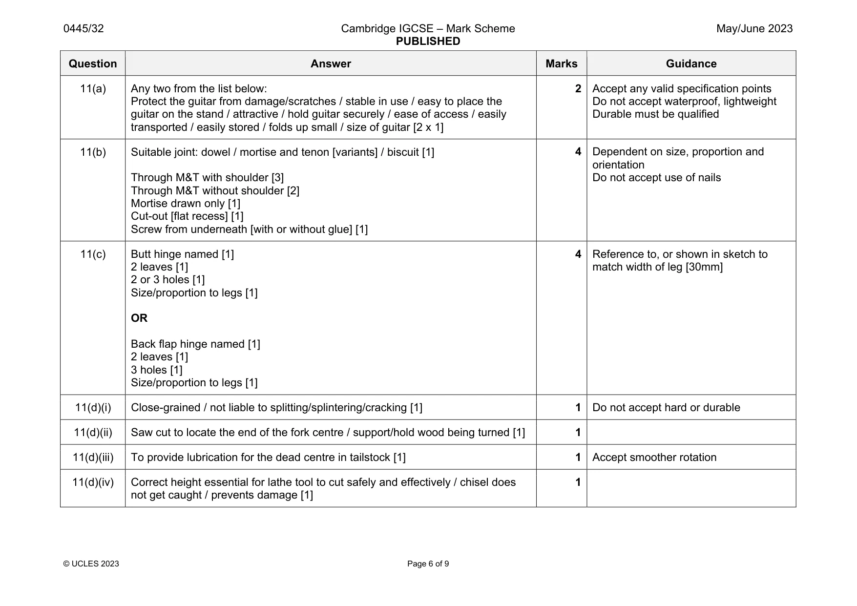
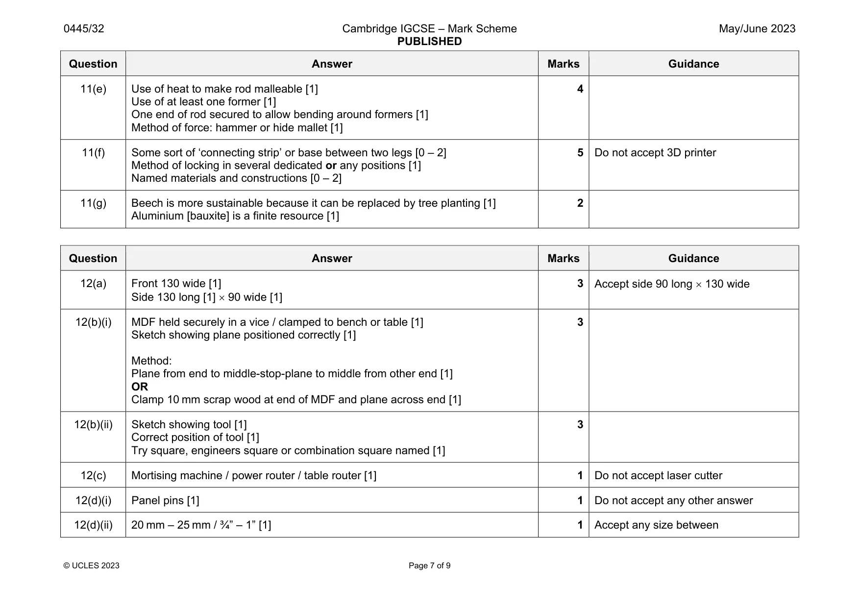
Mark scheme: 11(a) Any two from the list below: Protect the guitar from damage/scratches / stable in use / easy to place the guitar on the stand / attractive / hold guitar securely / ease of access / easily transported / easily stored / folds up small / size of guitar [2 x 1] 2 Accept any valid specification points Do not accept waterproof, lightweight Durable must be qualified 11(b) Suitable joint: dowel / mortise and tenon [variants] / biscuit [1] Through M&T with shoulder [3] Through M&T without shoulder [2] Mortise drawn only [1] Cut-out [flat recess] [1] Screw from underneath [with or without glue] [1] 4 Dependent on size, proportion and orientation Do not accept use of nails 11(c) Butt hinge named [1] 2 leaves [1] 2 or 3 holes [1] Size/proportion to legs [1] OR Back flap hinge named [1] 2 leaves [1] 3 holes [1] Size/proportion to legs [1] 4 Reference to, or shown in sketch to match width of leg [30mm] 11(d)(i) Close-grained / not liable to splitting/splintering/cracking [1] 1 Do not accept hard or durable 11(d)(ii) Saw cut to locate the end of the fork centre / support/hold wood being turned [1] 1 11(d)(iii) To provide lubrication for the dead centre in tailstock [1] 1 Accept smoother rotation 11(d)(iv) Correct height essential for lathe tool to cut safely and effectively / chisel does not get caught / prevents damage [1] 1 Question Answer Marks Guidance 11(e) Use of heat to make rod malleable [1] Use of at least one former [1] One end of rod secured to allow bending around formers [1] Method of force: hammer or hide mallet [1] 4 11(f) Some sort of ‘connecting strip’ or base between two legs [0 – 2] Method of locking in several dedicated or any positions [1] Named materials and constructions [0 – 2] 5 Do not accept 3D printer 11(g) Beech is more sustainable because it can be replaced by tree planting [1] Aluminium [bauxite] is a finite resource [1] 2
Q12 · Views of an incomplete design for a coin box used by children
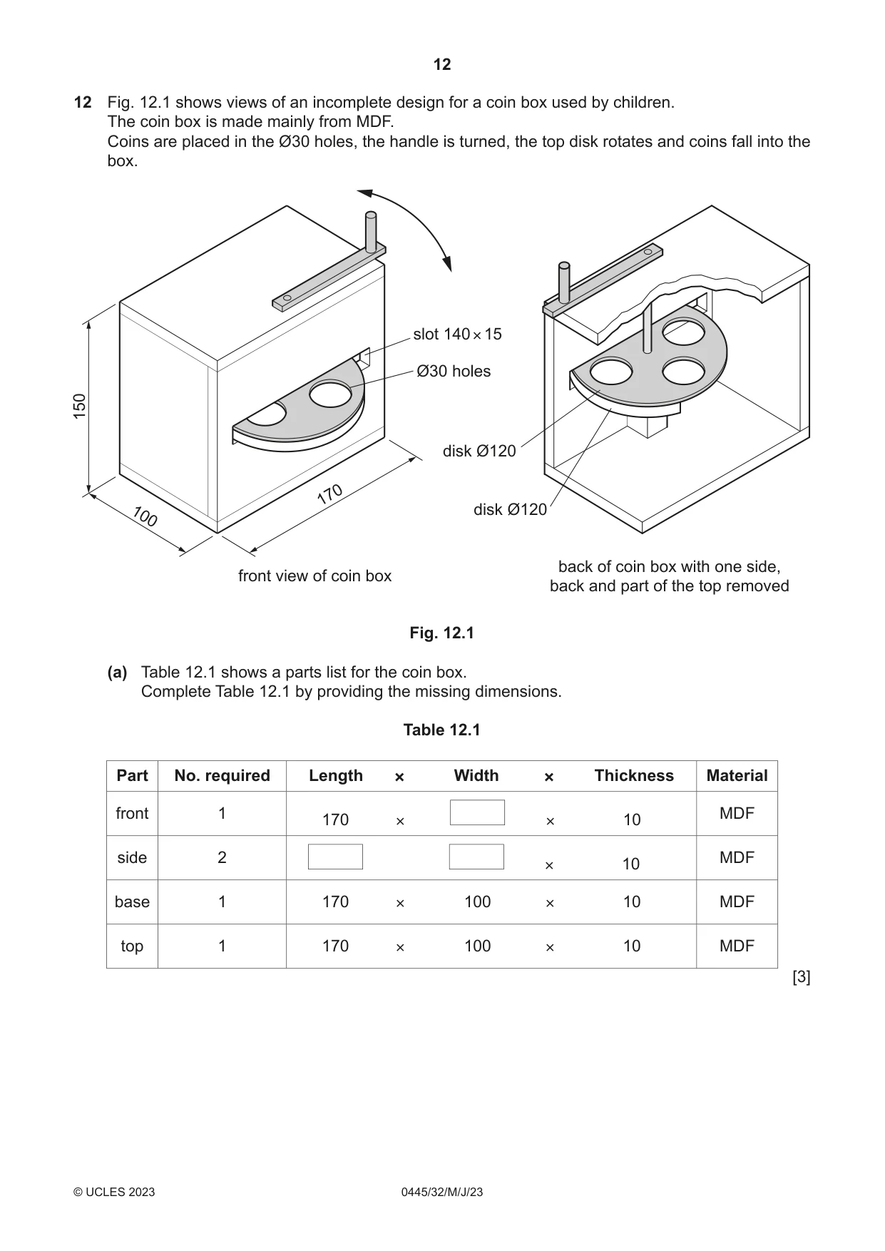
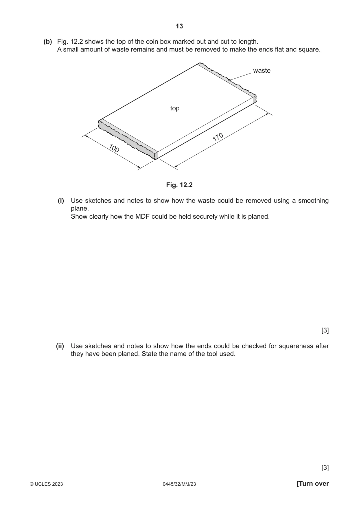
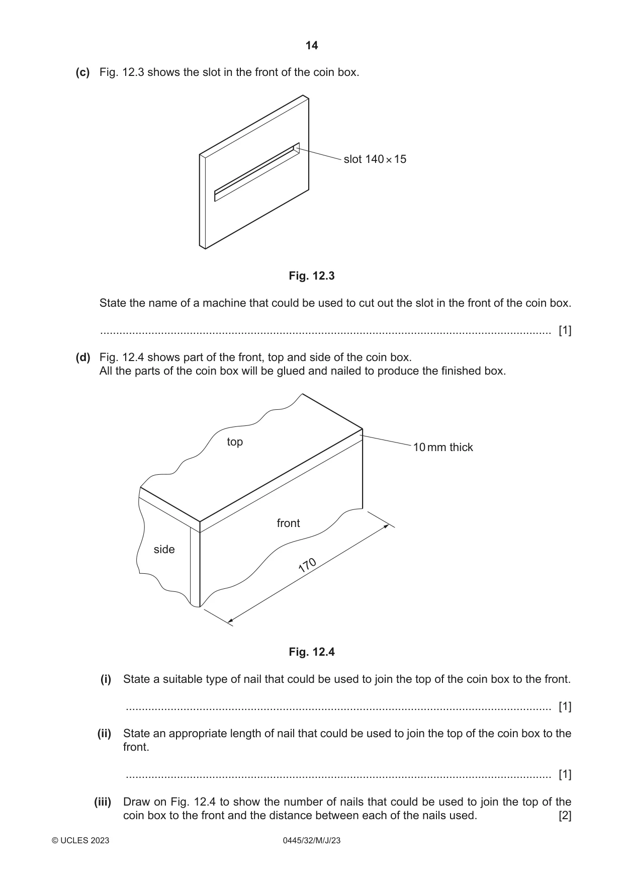
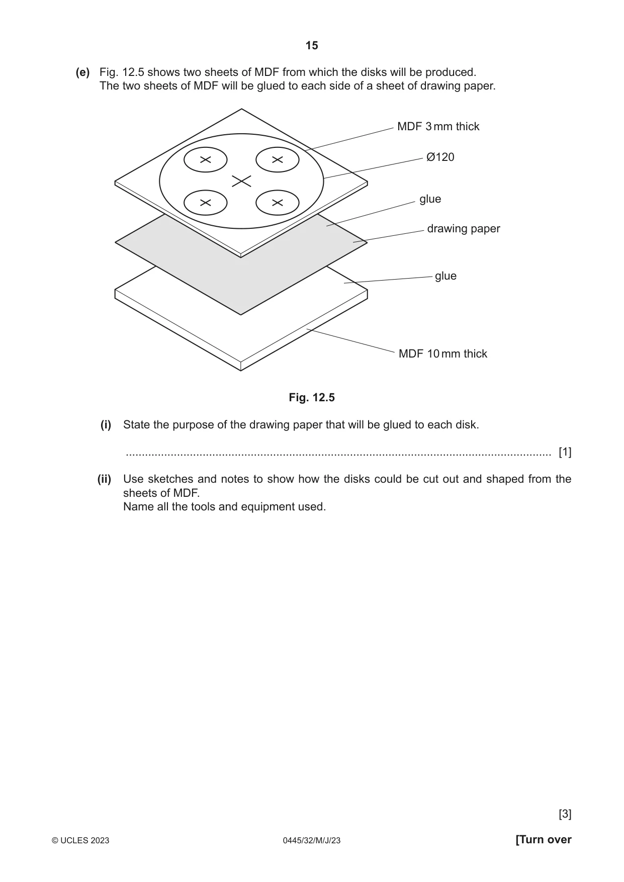
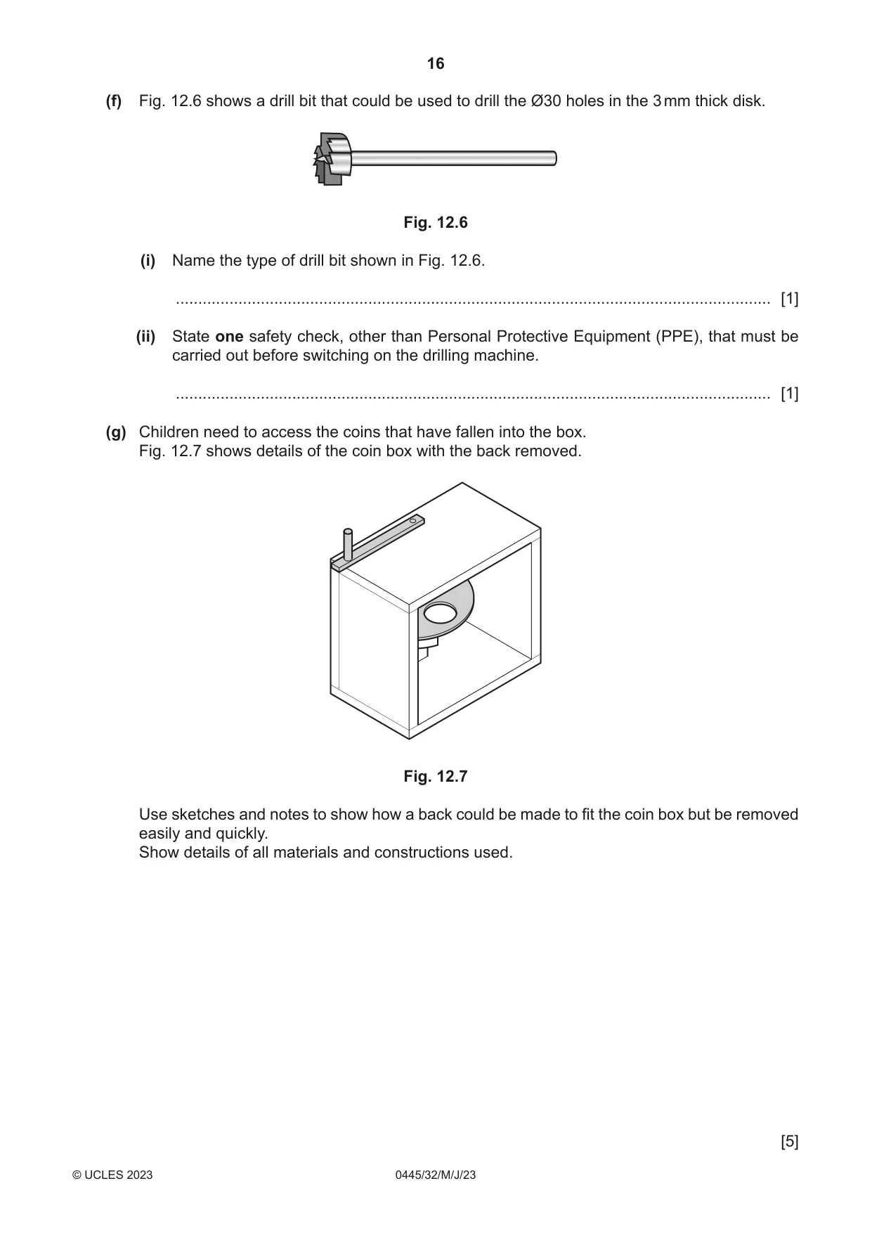
12 Fig. 12.1 shows views of an incomplete design for a coin box used by children. The coin box is made mainly from MDF. Coins are placed in the Ø30 holes, the handle is turned, the top disk rotates and coins fall into the box. slot 140 × 15 Ø30 holes 150 disk Ø120 170 100 disk Ø120 back of coin box with one side, front view of coin box back and part of the top removed Fig. 12.1 (a) Table 12.1 shows a parts list for the coin box. Complete Table 12.1 by providing the missing dimensions. Table 12.1 Part No. required Length × Width × Thickness Material front 1 MDF 170 × × 10 side 2 MDF × 10 base 1 170 × 100 × 10 MDF top 1 170 × 100 × 10 MDF [3] (b) Fig. 12.2 shows the top of the coin box marked out and cut to length. A small amount of waste remains and must be removed to make the ends flat and square. waste top 170 100 Fig. 12.2 (i) Use sketches and notes to show how the waste could be removed using a smoothing plane. Show clearly how the MDF could be held securely while it is planed. [3] (ii) Use sketches and notes to show how the ends could be checked for squareness after they have been planed. State the name of the tool used. [3] (c) Fig. 12.3 shows the slot in the front of the coin box. slot 140 × 15 Fig. 12.3 State the name of a machine that could be used to cut out the slot in the front of the coin box. ............................................................................................................................................. [1] (d) Fig. 12.4 shows part of the front, top and side of the coin box. All the parts of the coin box will be glued and nailed to produce the finished box. top 10 mm thick front side 170 Fig. 12.4 (i) State a suitable type of nail that could be used to join the top of the coin box to the front. ..................................................................................................................................... [1] (ii) State an appropriate length of nail that could be used to join the top of the coin box to the front. ..................................................................................................................................... [1] (iii) Draw on Fig. 12.4 to show the number of nails that could be used to join the top of the coin box to the front and the distance between each of the nails used. [2] (e) Fig. 12.5 shows two sheets of MDF from which the disks will be produced. The two sheets of MDF will be glued to each side of a sheet of drawing paper. MDF 3 mm thick Ø120 glue drawing paper glue MDF 10 mm thick Fig. 12.5 (i) State the purpose of the drawing paper that will be glued to each disk. ..................................................................................................................................... [1] (ii) Use sketches and notes to show how the disks could be cut out and shaped from the sheets of MDF. Name all the tools and equipment used. [3] (f) Fig. 12.6 shows a drill bit that could be used to drill the Ø30 holes in the 3 mm thick disk. Fig. 12.6 (i) Name the type of drill bit shown in Fig. 12.6. ..................................................................................................................................... [1] (ii) State one safety check, other than Personal Protective Equipment (PPE), that must be carried out before switching on the drilling machine. ..................................................................................................................................... [1] (g) Children need to access the coins that have fallen into the box. Fig. 12.7 shows details of the coin box with the back removed. Fig. 12.7 Use sketches and notes to show how a back could be made to fit the coin box but be removed easily and quickly. Show details of all materials and constructions used. [5]
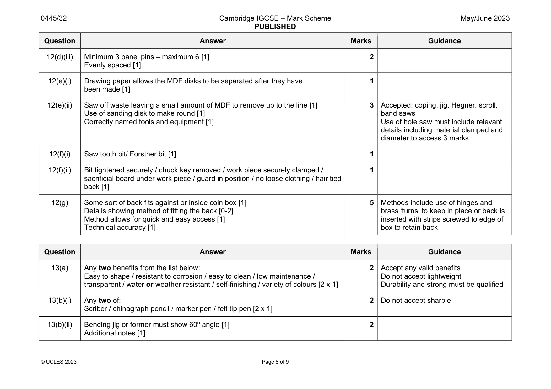
Mark scheme: 12(a) Front 130 wide [1] Side 130 long [1] 90 wide [1] 12(b)(i) MDF held securely in a vice / clamped to bench or table [1] Sketch showing plane positioned correctly [1] Method: Plane from end to middle-stop-plane to middle from other end [1] OR Clamp 10 mm scrap wood at end of MDF and plane across end [1] 3 12(b)(ii) Sketch showing tool [1] Correct position of tool [1] Try square, engineers square or combination square named [1] 3 12(c) Mortising machine / power router / table router [1] 1 Do not accept laser cutter 12(d)(i) Panel pins [1] 1 Do not accept any other answer 12(d)(ii) 20 mm – 25 mm / ¾” – 1” [1] 1 Accept any size between Question Answer Marks Guidance 12(d)(iii) Minimum 3 panel pins – maximum 6 [1] Evenly spaced [1] 2 12(e)(i) Drawing paper allows the MDF disks to be separated after they have been made [1] 1 12(e)(ii) Saw off waste leaving a small amount of MDF to remove up to the line [1] Use of sanding disk to make round [1] Correctly named tools and equipment [1] 3 Accepted: coping, jig, Hegner, scroll, band saws Use of hole saw must include relevant details including material clamped and diameter to access 3 marks 12(f)(i) Saw tooth bit/ Forstner bit [1] 1 12(f)(ii) Bit tightened securely / chuck key removed / work piece securely clamped / sacrificial board under work piece / guard in position / no loose clothing / hair tied back [1] 1 12(g) Some sort of back fits against or inside coin box [1] Details showing method of fitting the back [0-2] Method allows for quick and easy access [1] Technical accuracy [1] 5 Methods include use of hinges and brass ‘turns’ to keep in place or back is inserted with strips screwed to edge of box to retain back
Q13 · A bird feeder made of 5 mm thick clear acrylic
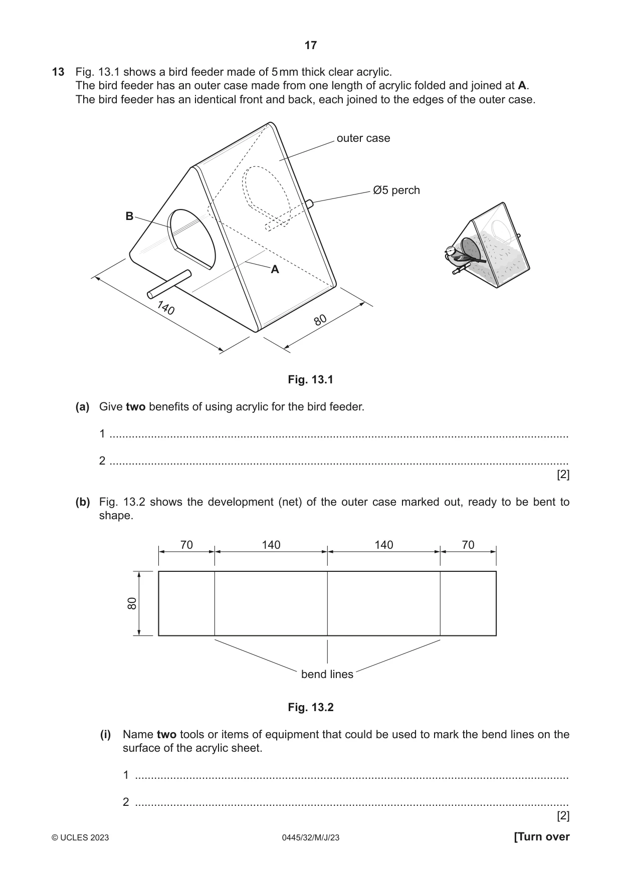
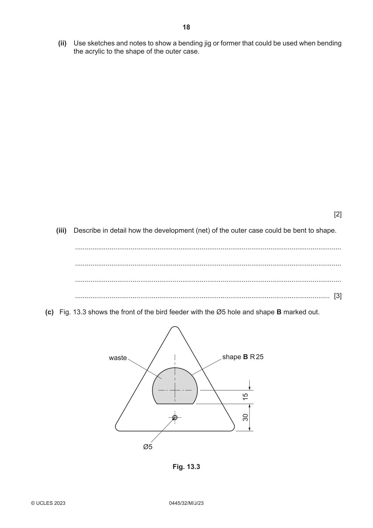
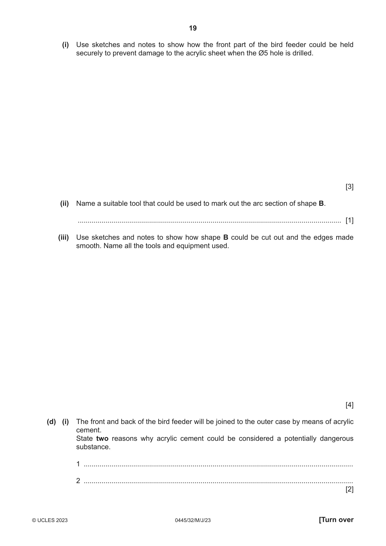
13 Fig. 13.1 shows a bird feeder made of 5 mm thick clear acrylic. The bird feeder has an outer case made from one length of acrylic folded and joined at A. The bird feeder has an identical front and back, each joined to the edges of the outer case. outer case Ø5 perch B A 140 80 Fig. 13.1 (a) Give two benefits of using acrylic for the bird feeder. 1 ................................................................................................................................................ 2 ................................................................................................................................................ [2] (b) Fig. 13.2 shows the development (net) of the outer case marked out, ready to be bent to shape. 70 140 140 70 80 bend lines Fig. 13.2 (i) Name two tools or items of equipment that could be used to mark the bend lines on the surface of the acrylic sheet. 1 ........................................................................................................................................ 2 ........................................................................................................................................ [2] (ii) Use sketches and notes to show a bending jig or former that could be used when bending the acrylic to the shape of the outer case. [2] (iii) Describe in detail how the development (net) of the outer case could be bent to shape. ........................................................................................................................................... ........................................................................................................................................... ........................................................................................................................................... ..................................................................................................................................... [3] (c) Fig. 13.3 shows the front of the bird feeder with the Ø5 hole and shape B marked out. waste shape B R 25 15 30 Ø5 Fig. 13.3 (i) Use sketches and notes to show how the front part of the bird feeder could be held securely to prevent damage to the acrylic sheet when the Ø5 hole is drilled. [3] (ii) Name a suitable tool that could be used to mark out the arc section of shape B. ..................................................................................................................................... [1] (iii) Use sketches and notes to show how shape B could be cut out and the edges made smooth. Name all the tools and equipment used. [4] (d) (i) The front and back of the bird feeder will be joined to the outer case by means of acrylic cement. State two reasons why acrylic cement could be considered a potentially dangerous substance. 1 ........................................................................................................................................ 2 ........................................................................................................................................ [2]
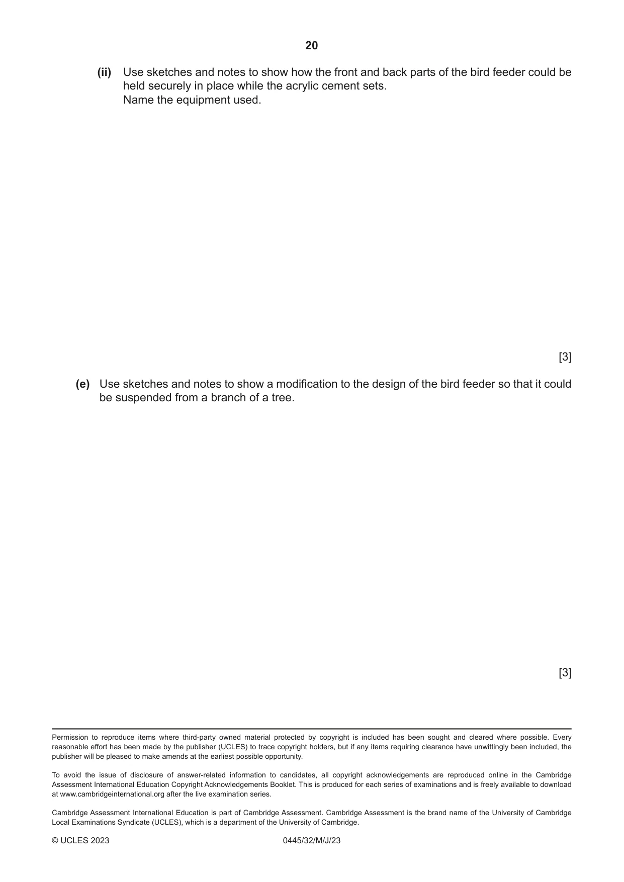
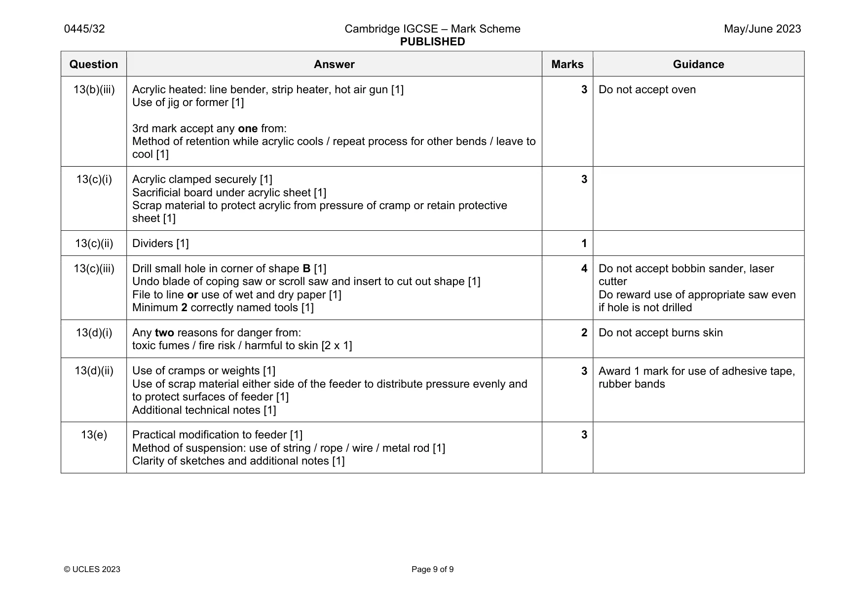
Mark scheme: 13(a) Any two benefits from the list below: Easy to shape / resistant to corrosion / easy to clean / low maintenance / transparent / water or weather resistant / self-finishing / variety of colours [2 x 1] 2 Accept any valid benefits Do not accept lightweight Durability and strong must be qualified 13(b)(i) Any two of: Scriber / chinagraph pencil / marker pen / felt tip pen [2 x 1] 2 Do not accept sharpie 13(b)(ii) Bending jig or former must show 60º angle [1] Additional notes [1] 2 Question Answer Marks Guidance 13(b)(iii) Acrylic heated: line bender, strip heater, hot air gun [1] Use of jig or former [1] 3rd mark accept any one from: Method of retention while acrylic cools / repeat process for other bends / leave to cool [1] 3 Do not accept oven 13(c)(i) Acrylic clamped securely [1] Sacrificial board under acrylic sheet [1] Scrap material to protect acrylic from pressure of cramp or retain protective sheet [1] 3 13(c)(ii) Dividers [1] 1 13(c)(iii) Drill small hole in corner of shape B [1] Undo blade of coping saw or scroll saw and insert to cut out shape [1] File to line or use of wet and dry paper [1] Minimum 2 correctly named tools [1] 4 Do not accept bobbin sander, laser cutter Do reward use of appropriate saw even if hole is not drilled 13(d)(i) Any two reasons for danger from: toxic fumes / fire risk / harmful to skin [2 x 1] 2 Do not accept burns skin 13(d)(ii) Use of cramps or weights [1] Use of scrap material either side of the feeder to distribute pressure evenly and to protect surfaces of feeder [1] Additional technical notes [1] 3 Award 1 mark for use of adhesive tape, rubber bands 13(e) Practical modification to feeder [1] Method of suspension: use of string / rope / wire / metal rod [1] Clarity of sketches and additional notes [1] 3
What was in this paper
The subtopics covered by these 13 questions, and how many questions each got. Open one in a new tab to see every Cambridge question on it.
What you needed in this session
Cambridge’s own grade thresholds for 2023 May/June, Paper 3 · Variant 2. A higher threshold means an easier paper — the bar moves with how the cohort did.