Cambridge IGCSE Design and Technology 0445 — 2024 Oct/Nov Paper 3 · Variant 2
0445/32/O/N/24 · 13 questions · 50 marks · 60 min
The question paper and its mark scheme, free to read here and free to download. This is Cambridge’s own paper, exactly as it was sat.
Question paper24 pages
Mark scheme9 pages
Answers below. Sit the paper first if you are practising.
Questions as text
Q1 · Carbon fibre reinforced plastic (CFRP) is used to build many different aircraft parts
1 Carbon fibre reinforced plastic (CFRP) is used to build many different aircraft parts. State two benefits of using carbon fibre reinforced plastic (CFRP) to build aircraft parts. 1 ....................................................................................................................................................... 2 ....................................................................................................................................................... [2]
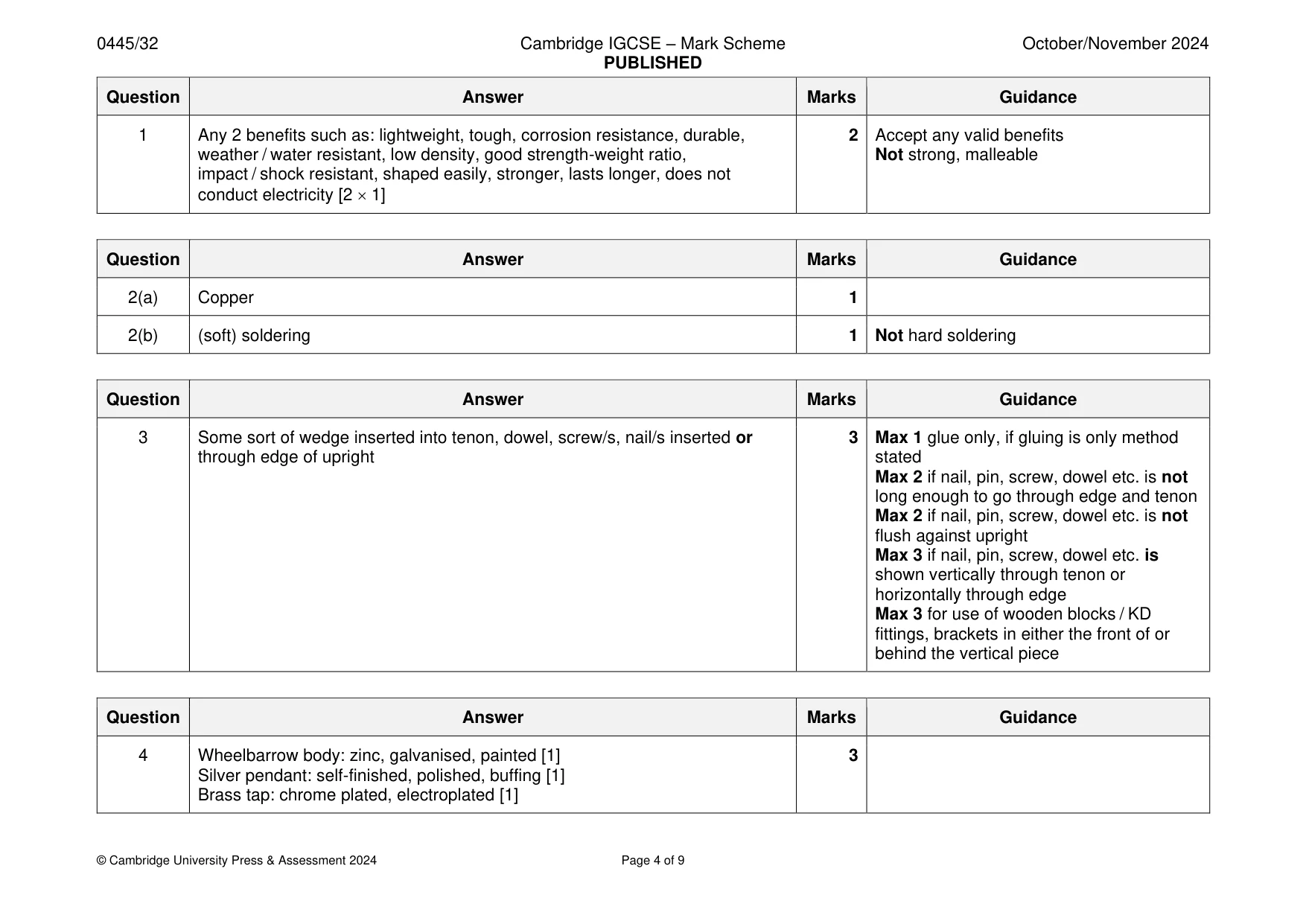
Mark scheme: Question Answer Marks Guidance 1 Any 2 benefits such as: lightweight, tough, corrosion resistance, durable, 2 Accept any valid benefits weather / water resistant, low density, good strength-weight ratio, Not strong, malleable impact / shock resistant, shaped easily, stronger, lasts longer, does not conduct electricity [2 1]
Q2 · Pipes used for plumbing being joined together
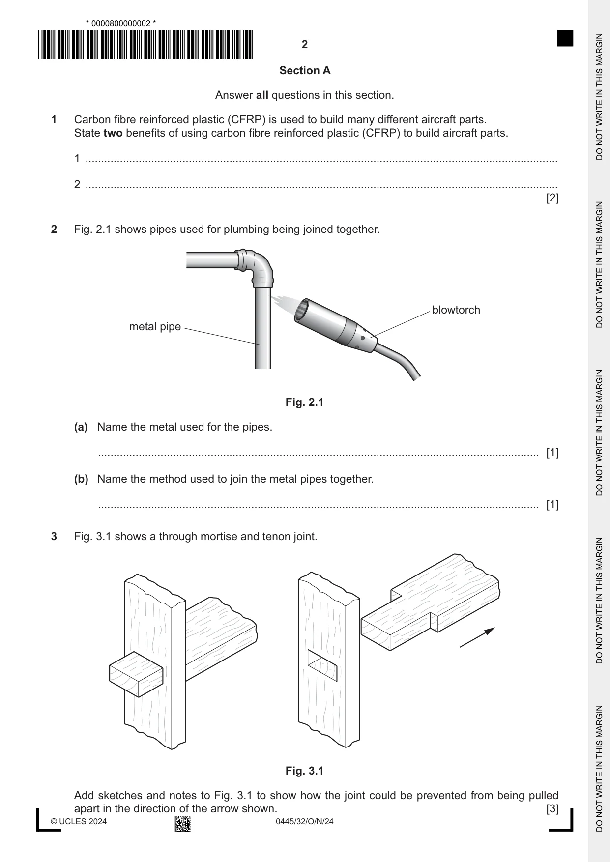
2 Fig. 2.1 shows pipes used for plumbing being joined together. blowtorch metal pipe Fig. 2.1 (a) Name the metal used for the pipes. ............................................................................................................................................. [1] (b) Name the method used to join the metal pipes together. ............................................................................................................................................. [1]
Mark scheme: 2(a) Copper 1 2(b) (soft) soldering 1 Not hard soldering
Q3 · A through mortise and tenon joint
3 Fig. 3.1 shows a through mortise and tenon joint. Fig. 3.1 Add sketches and notes to Fig. 3.1 to show how the joint could be prevented from being pulled apart in the directio the arrow shown. [3]
Mark scheme: 3 Some sort of wedge inserted into tenon, dowel, screw/s, nail/s inserted or 3 Max 1 glue only, if gluing is only method through edge of upright stated Max 2 if nail, pin, screw, dowel etc. is not long enough to go through edge and tenon Max 2 if nail, pin, screw, dowel etc. is not flush against upright Max 3 if nail, pin, screw, dowel etc. is shown vertically through tenon or horizontally through edge Max 3 for use of wooden blocks / KD fittings, brackets in either the front of or behind the vertical piece
Q4 · Three products made of different materials
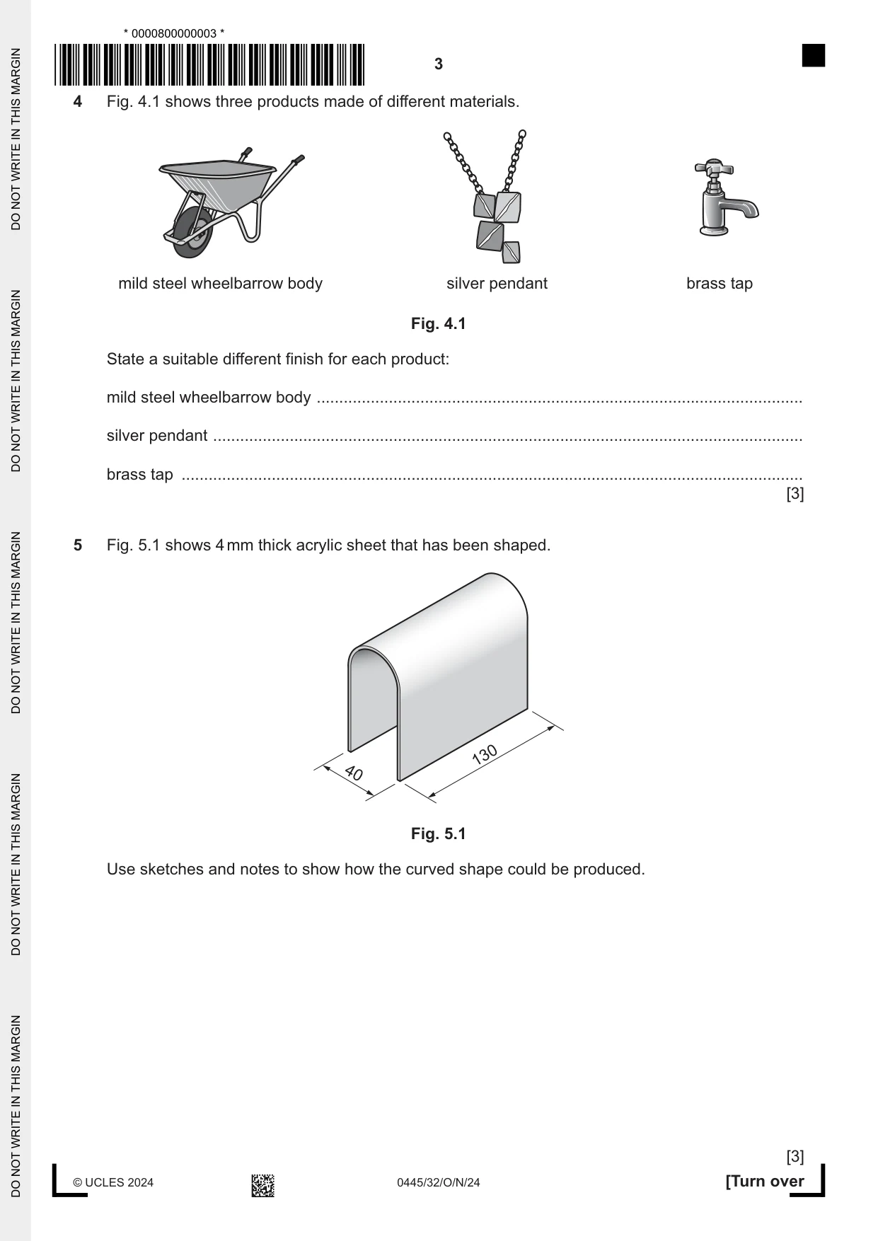
4 Fig. 4.1 shows three products made of different materials. mild steel wheelbarrow body silver pendant brass tap Fig. 4.1 State a suitable different finish for each product: mild steel wheelbarrow body ............................................................................................................ silver pendant ................................................................................................................................... brass tap .......................................................................................................................................... [3]
Mark scheme: 4 Wheelbarrow body: zinc, galvanised, painted [1] 3 Silver pendant: self-finished, polished, buffing [1] Brass tap: chrome plated, electroplated [1]
Q5 · 4 mm thick acrylic sheet that has been shaped
5 Fig. 5.1 shows 4 mm thick acrylic sheet that has been shaped. 130 40 Fig. 5.1 Use sketches and notes to show how the curved shape could be produced. [3]
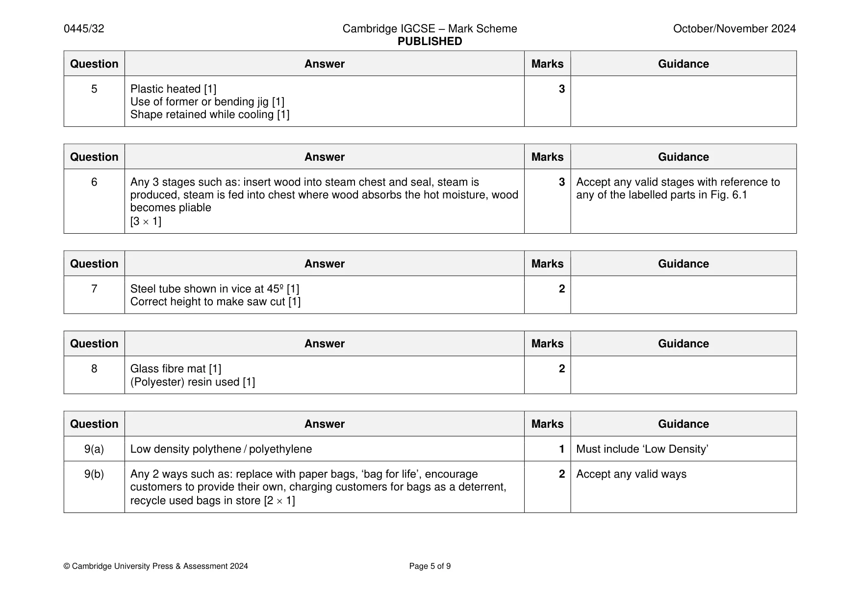
Mark scheme: 5 Plastic heated [1] 3 Use of former or bending jig [1] Shape retained while cooling [1]
Q6 · Details of a steam chest that would be used to steam bend wood
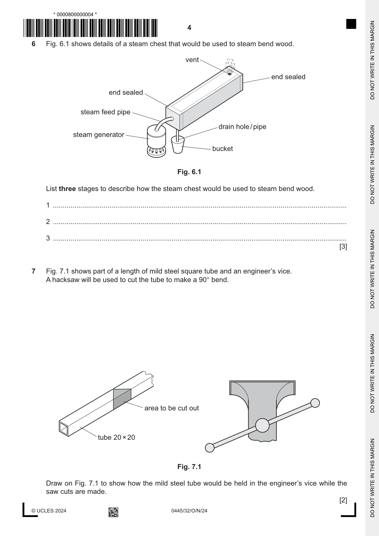
6 Fig. 6.1 shows details of a steam chest that would be used to steam bend wood. vent end sealed end sealed steam feed pipe drain hole / pipe steam generator bucket Fig. 6.1 List three stages to describe how the steam chest would be used to steam bend wood. 1 ....................................................................................................................................................... 2 ....................................................................................................................................................... 3 ....................................................................................................................................................... [3]
Mark scheme: 6 Any 3 stages such as: insert wood into steam chest and seal, steam is 3 Accept any valid stages with reference to produced, steam is fed into chest where wood absorbs the hot moisture, wood any of the labelled parts in Fig. 6.1 becomes pliable [3 1]
Q7 · Part of a length of mild steel square tube and an engineer’s vice
7 Fig. 7.1 shows part of a length of mild steel square tube and an engineer’s vice. A hacksaw will be used to cut the tube to make a 90° bend. area to be cut out tube 20 × 20 Fig. 7.1 Draw on Fig. 7.1 to show how the mild steel tube would be held in the engineer’s vice while the saw cuts are made. [2]
Mark scheme: 7 Steel tube shown in vice at 45º [1] 2 Correct height to make saw cut [1]
Q8 · A body shell for a car made from glass reinforced plastic (GRP)
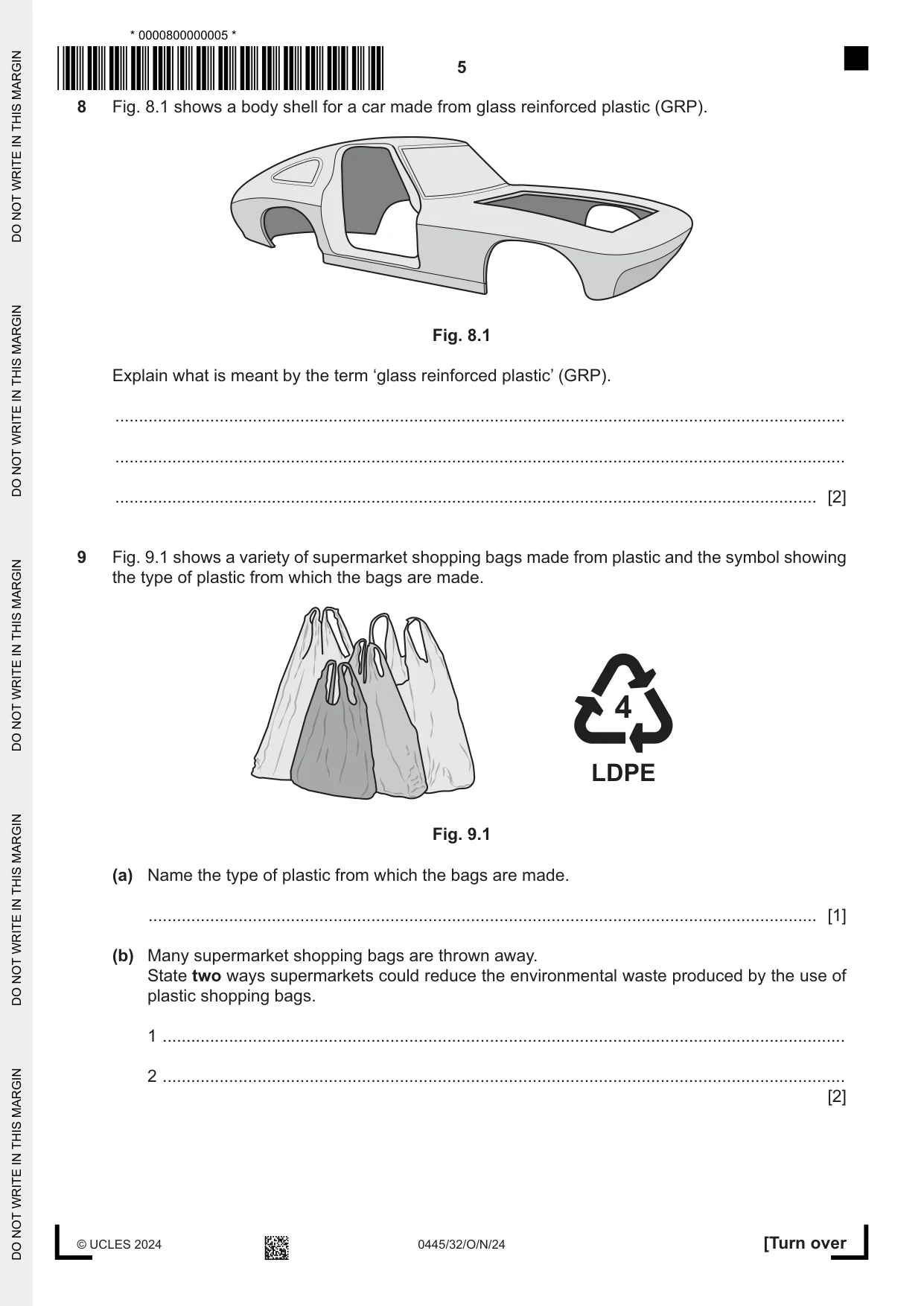
8 Fig. 8.1 shows a body shell for a car made from glass reinforced plastic (GRP). Fig. 8.1 Explain what is meant by the term ‘glass reinforced plastic’ (GRP). .......................................................................................................................................................... .......................................................................................................................................................... .................................................................................................................................................... [2]
Mark scheme: 8 Glass fibre mat [1] 2 (Polyester) resin used [1]
Q9 · A variety of supermarket shopping bags made from plastic and the symbol showing the type…
9 Fig. 9.1 shows a variety of supermarket shopping bags made from plastic and the symbol showing the type of plastic from which the bags are made. 4 LDPE Fig. 9.1 (a) Name the type of plastic from which the bags are made. ............................................................................................................................................. [1] (b) Many supermarket shopping bags are thrown away. State two ways supermarkets could reduce the environmental waste produced by the use of plastic shopping bags. 1 ................................................................................................................................................ 2 ................................................................................................................................................ [2]
Mark scheme: 9(a) Low density polythene / polyethylene 1 Must include ‘Low Density’ 9(b) Any 2 ways such as: replace with paper bags, ‘bag for life’, encourage 2 Accept any valid ways customers to provide their own, charging customers for bags as a deterrent, recycle used bags in store [2 1]
Q10 · Two hardwood stools, A and B
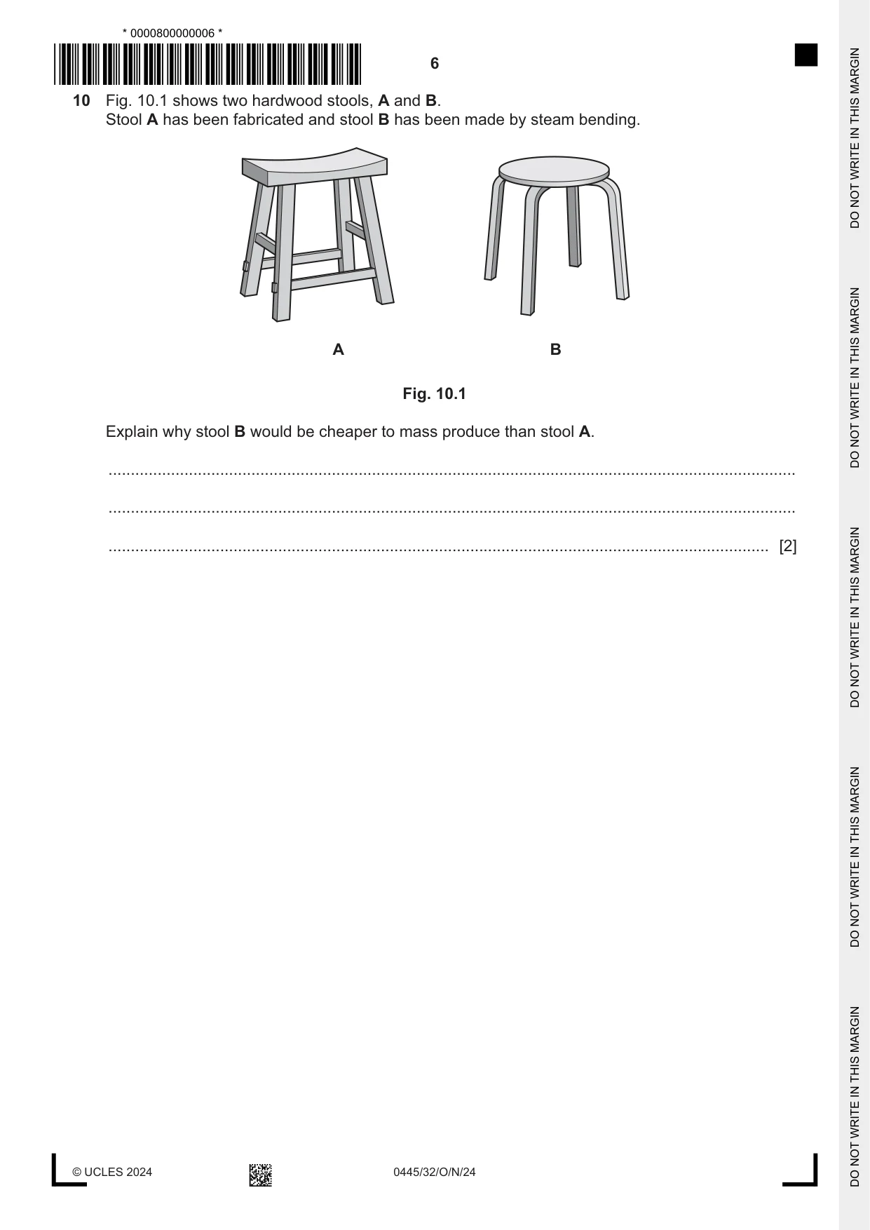
10 Fig. 10.1 shows two hardwood stools, A and B. Stool A has been fabricated and stool B has been made by steam bending. A B Fig. 10.1 Explain why stool B would be cheaper to mass produce than stool A. .......................................................................................................................................................... .......................................................................................................................................................... .................................................................................................................................................... [2]
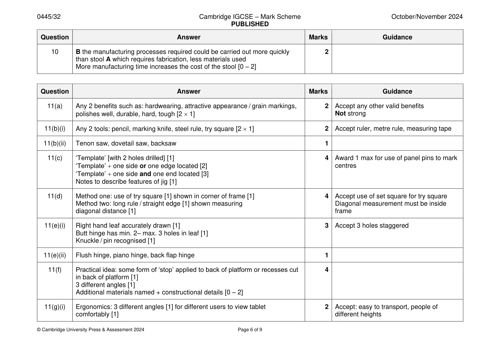
Mark scheme: 10 B the manufacturing processes required could be carried out more quickly 2 than stool A which requires fabrication, less materials used More manufacturing time increases the cost of the stool [0 – 2]
Q11 · An incomplete design for a tablet stand made of hardwood
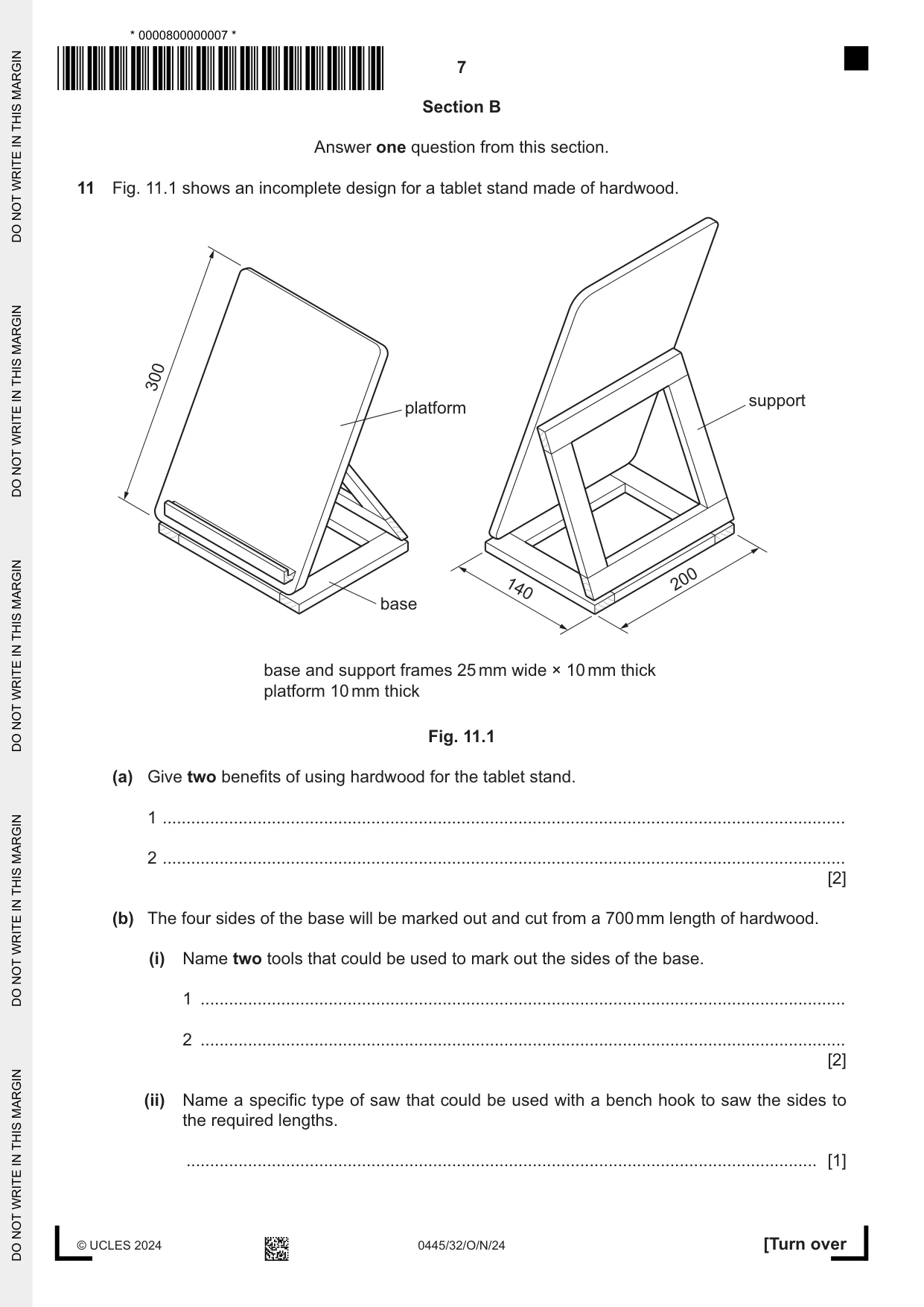
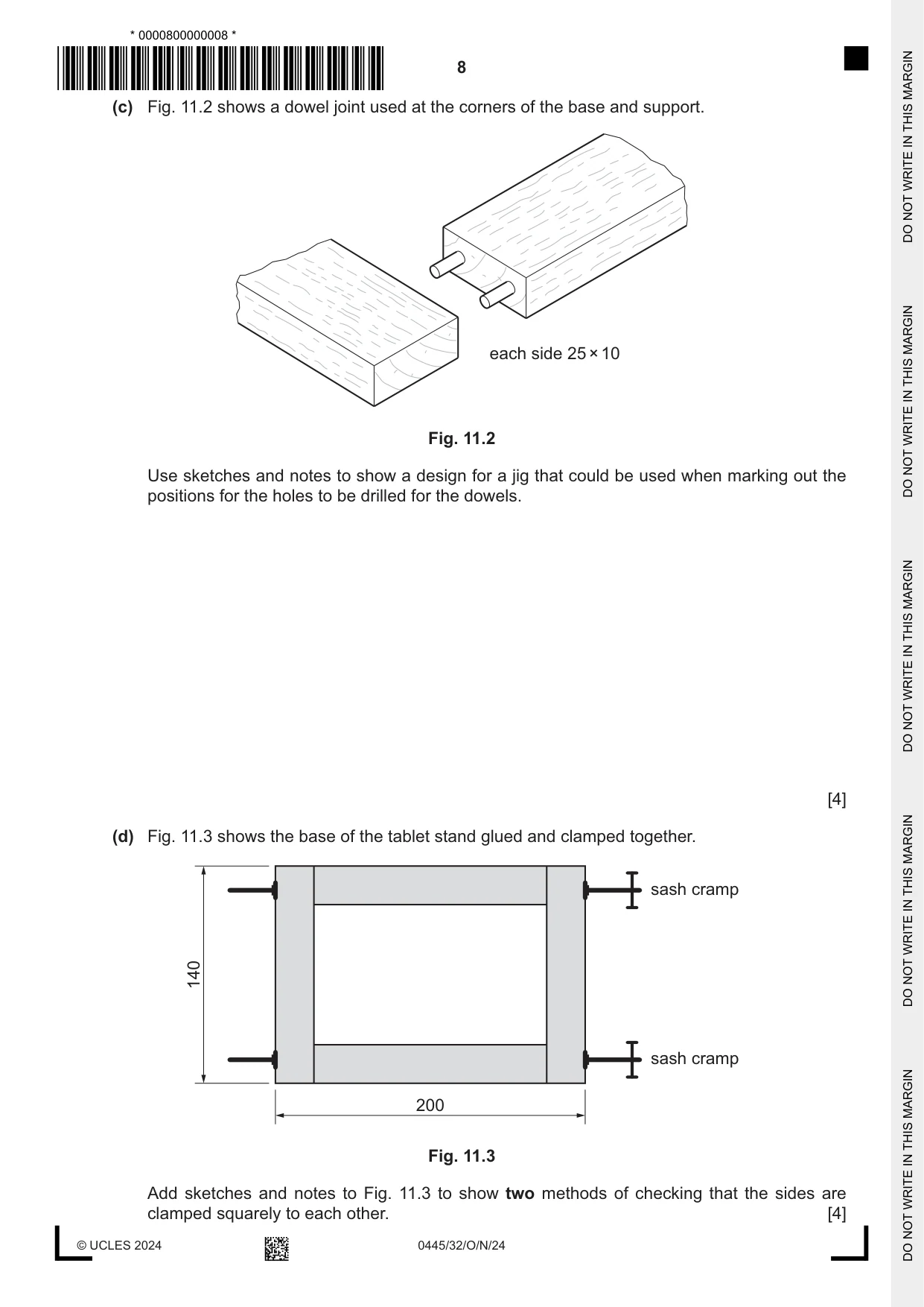
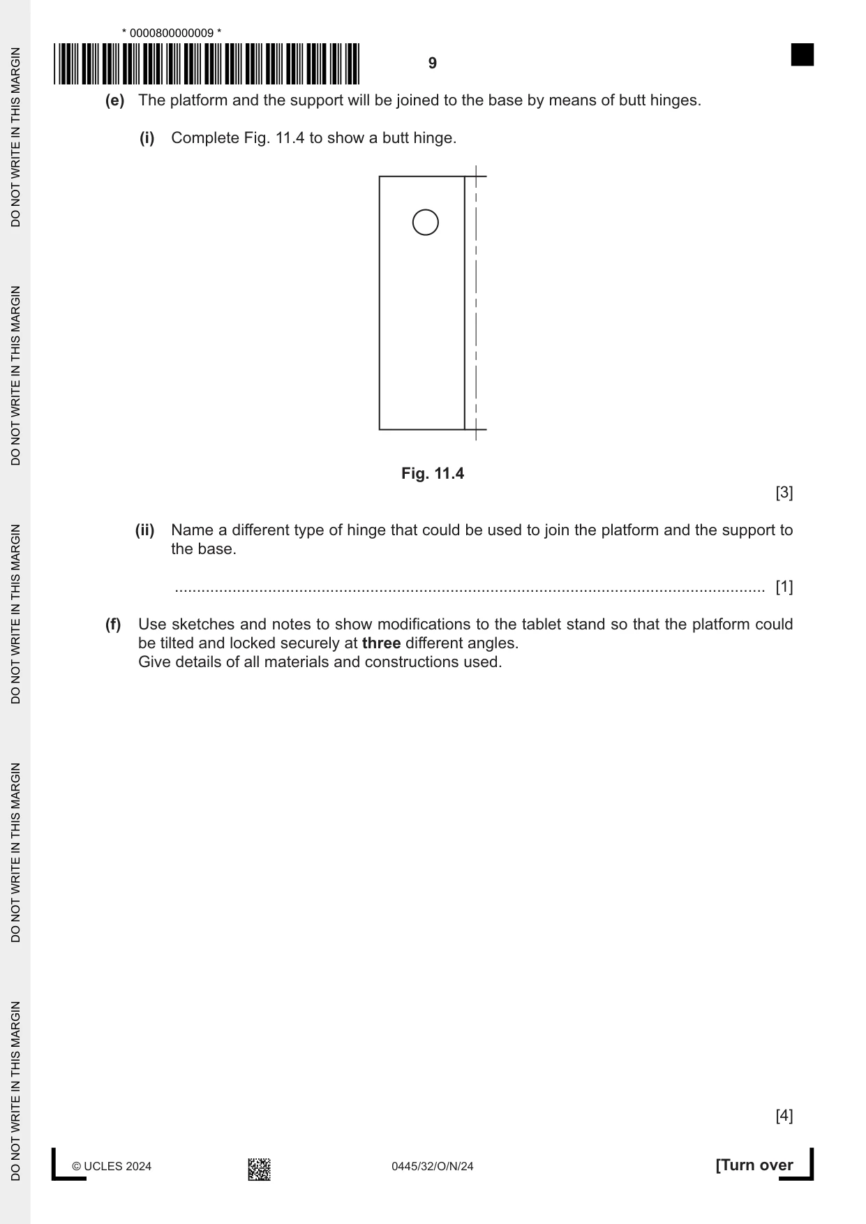
11 Fig. 11.1 shows an incomplete design for a tablet stand made of hardwood. 300 support platform 200 140 base base and support frames 25 mm wide × 10 mm thick platform 10 mm thick Fig. 11.1 (a) Give two benefits of using hardwood for the tablet stand. 1 ................................................................................................................................................ 2 ................................................................................................................................................ [2] (b) The four sides of the base will be marked out and cut from a 700 mm length of hardwood. (i) Name two tools that could be used to mark out the sides of the base. 1 ........................................................................................................................................ 2 ........................................................................................................................................ [2] (ii) Name a specific type of saw that could be used with a bench hook to saw the sides to the required lengths. ..................................................................................................................................... [1] (c) Fig. 11.2 shows a dowel joint used at the corners of the base and support. each side 25 × 10 Fig. 11.2 Use sketches and notes to show a design for a jig that could be used when marking out the positions for the holes to be drilled for the dowels. [4] (d) Fig. 11.3 shows the base of the tablet stand glued and clamped together. sash cramp 140 sash cramp 200 Fig. 11.3 Add sketches and notes to Fig. 11.3 to show two methods of checking that the sides are clamped squarely to each other. [4] (e) The platform and the support will be joined to the base by means of butt hinges. (i) Complete Fig. 11.4 to show a butt hinge. Fig. 11.4 [3] (ii) Name a different type of hinge that could be used to join the platform and the support to the base. ..................................................................................................................................... [1] (f) Use sketches and notes to show modifications to the tablet stand so that the platform could be tilted and locked securely at three different angles. Give details of all materials and constructions used. [4] (g) Describe one way in which the designer has considered each of the following when designing the tablet stand. (i) ergonomics ........................................................................................................................................... ..................................................................................................................................... [2] (ii) sustainability of materials used ........................................................................................................................................... ..................................................................................................................................... [2]
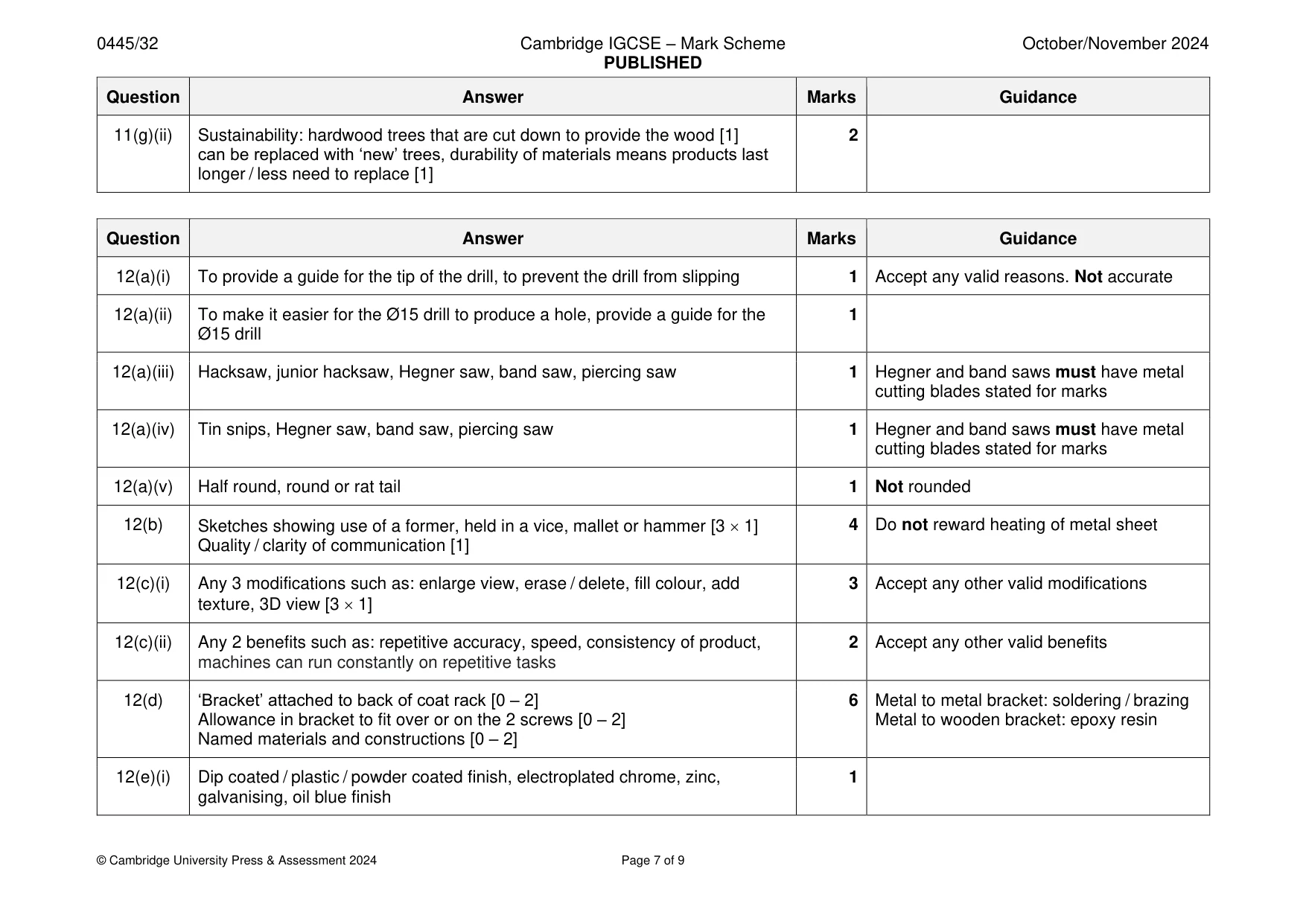
Mark scheme: 11(a) Any 2 benefits such as: hardwearing, attractive appearance / grain markings, 2 Accept any other valid benefits polishes well, durable, hard, tough [2 1] Not strong 11(b)(i) Any 2 tools: pencil, marking knife, steel rule, try square [2 1] 2 Accept ruler, metre rule, measuring tape 11(b)(ii) Tenon saw, dovetail saw, backsaw 1 11(c) ‘Template’ [with 2 holes drilled] [1] 4 Award 1 max for use of panel pins to mark ‘Template’ + one side or one edge located [2] centres ‘Template’ + one side and one end located [3] Notes to describe features of jig [1] 11(d) Method one: use of try square [1] shown in corner of frame [1] 4 Accept use of set square for try square Method two: long rule / straight edge [1] shown measuring Diagonal measurement must be inside diagonal distance [1] frame 11(e)(i) Right hand leaf accurately drawn [1] 3 Accept 3 holes staggered Butt hinge has min. 2– max. 3 holes in leaf [1] Knuckle / pin recognised [1] 11(e)(ii) Flush hinge, piano hinge, back flap hinge 1 11(f) Practical idea: some form of ‘stop’ applied to back of platform or recesses cut 4 in back of platform [1] 3 different angles [1] Additional materials named + constructional details [0 – 2] 11(g)(i) Ergonomics: 3 different angles [1] for different users to view tablet 2 Accept: easy to transport, people of comfortably [1] different heights 11(g)(ii) Sustainability: hardwood trees that are cut down to provide the wood [1] 2 can be replaced with ‘new’ trees, durability of materials means products last longer / less need to replace [1]
Q12 · An incomplete design for a coat hook used by children
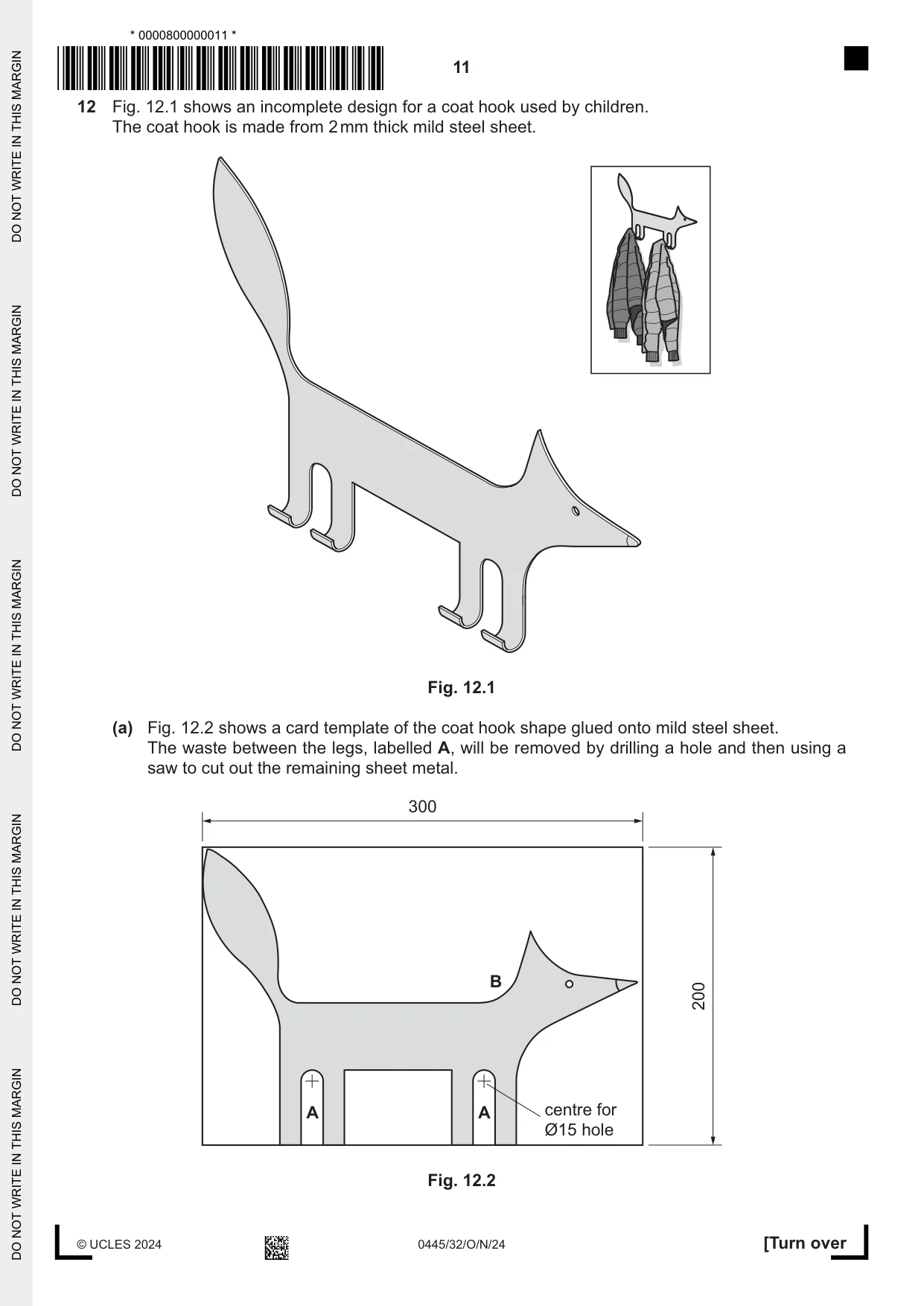
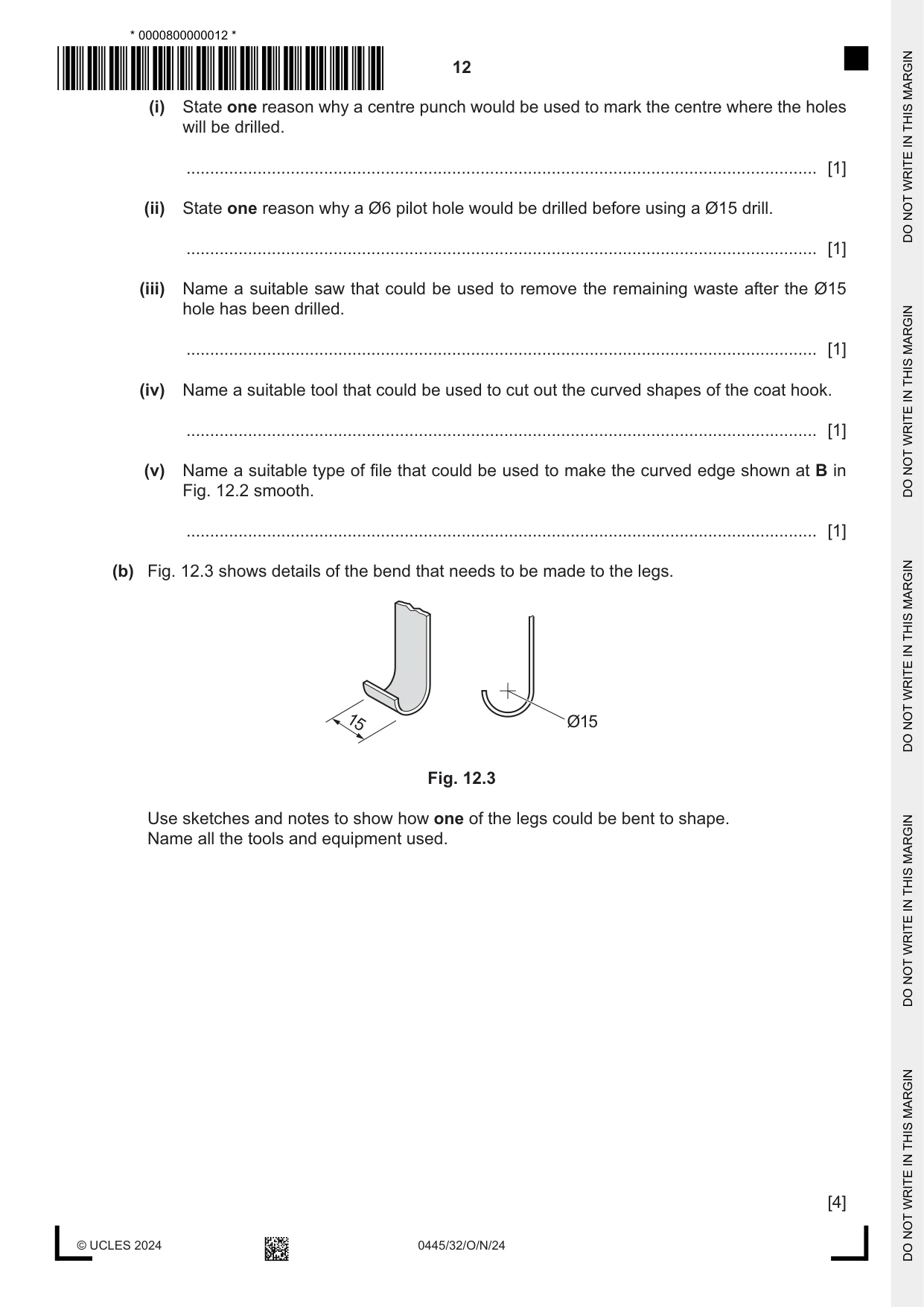
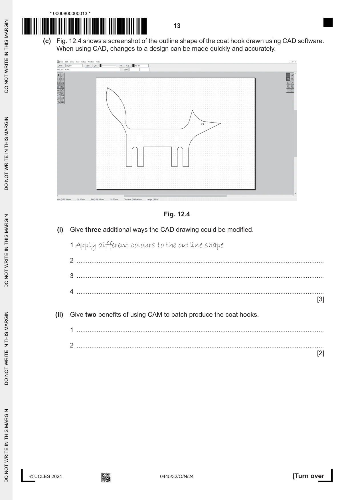
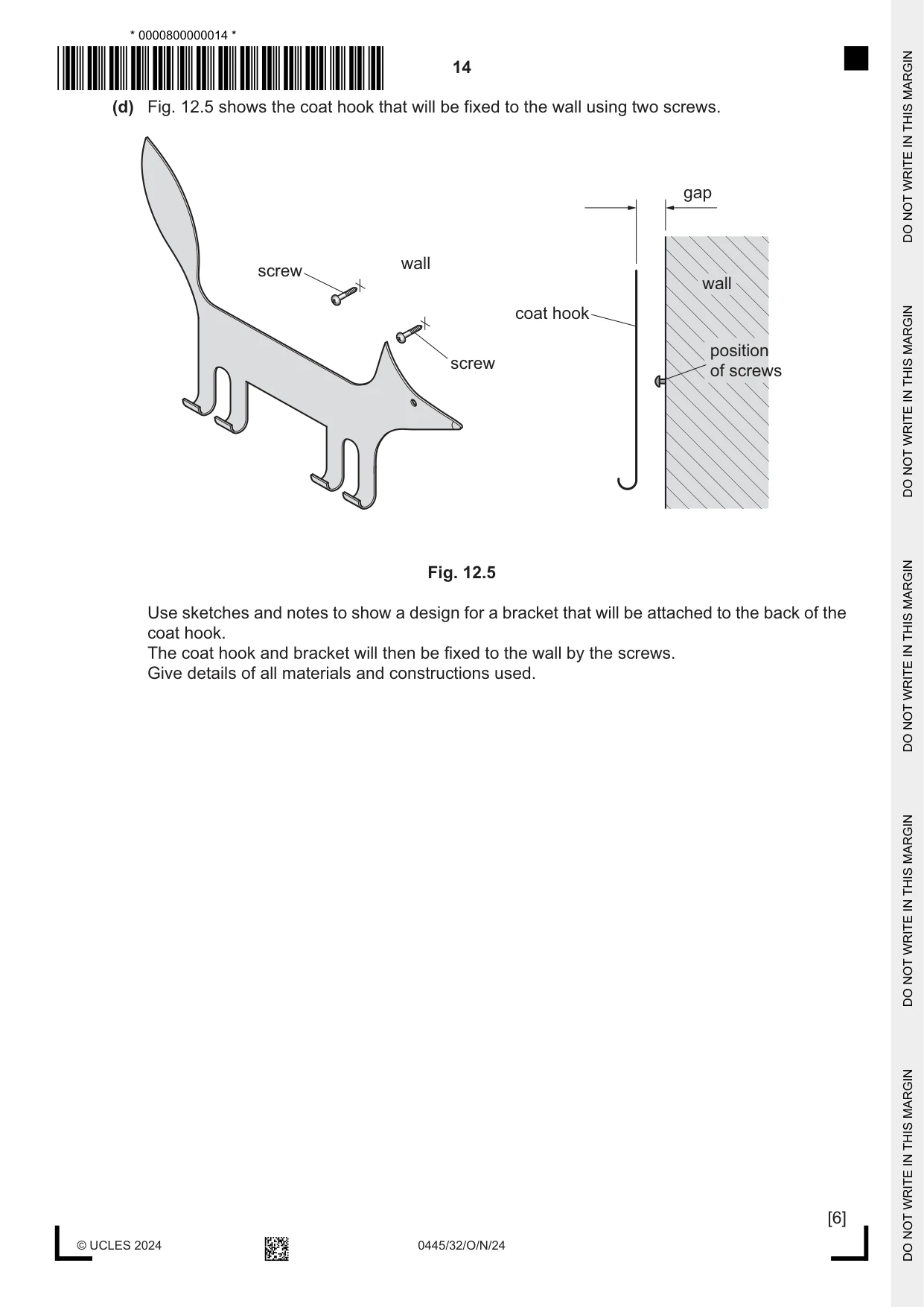
12 Fig. 12.1 shows an incomplete design for a coat hook used by children. The coat hook is made from 2 mm thick mild steel sheet. Fig. 12.1 (a) Fig. 12.2 shows a card template of the coat hook shape glued onto mild steel sheet. The waste between the legs, labelled A, will be removed by drilling a hole and then using a saw to cut out the remaining sheet metal. 300 B 200 A A centre for Ø15 hole Fig. 12.2 (i) State one reason why a centre punch would be used to mark the centre where the holes will be drilled. ..................................................................................................................................... [1] (ii) State one reason why a Ø6 pilot hole would be drilled before using a Ø15 drill. ..................................................................................................................................... [1] (iii) Name a suitable saw that could be used to remove the remaining waste after the Ø15 hole has been drilled. ..................................................................................................................................... [1] (iv) Name a suitable tool that could be used to cut out the curved shapes of the coat hook. ..................................................................................................................................... [1] (v) Name a suitable type of file that could be used to make the curved edge shown at B in Fig. 12.2 smooth. ..................................................................................................................................... [1] (b) Fig. 12.3 shows details of the bend that needs to be made to the legs. 15 Ø15 Fig. 12.3 Use sketches and notes to show how one of the legs could be bent to shape. Name all the tools and equipment used. [4] (c) Fig. 12.4 shows a screenshot of the outline shape of the coat hook drawn using CAD software. When using CAD, changes to a design can be made quickly and accurately. Fig. 12.4 (i) Give three additional ways the CAD drawing could be modified. 1 Apply different colours to the outline shape 2 ........................................................................................................................................ 3 ........................................................................................................................................ 4 ........................................................................................................................................ [3] (ii) Give two benefits of using CAM to batch produce the coat hooks. 1 ........................................................................................................................................ 2 ........................................................................................................................................ [2] (d) Fig. 12.5 shows the coat hook that will be fixed to the wall using two screws. gap wall screw wall coat hook position screw of screws Fig. 12.5 Use sketches and notes to show a design for a bracket that will be attached to the back of the coat hook. The coat hook and bracket will then be fixed to the wall by the screws. Give details of all materials and constructions used. [6] (e) Paint could be applied to the coat hook to improve the appearance of the mild steel sheet. (i) Name a suitable finish, other than paint, that could be applied to the mild steel sheet. ..................................................................................................................................... [1] (ii) Describe how the surfaces of the mild steel sheet could be prepared to take an applied finish. ........................................................................................................................................... ........................................................................................................................................... ..................................................................................................................................... [2] (f) The coat hook could be made from aluminium sheet. Give two advantages of using aluminium rather than mild steel for the coat hook. 1 ................................................................................................................................................ 2 ................................................................................................................................................ [2]
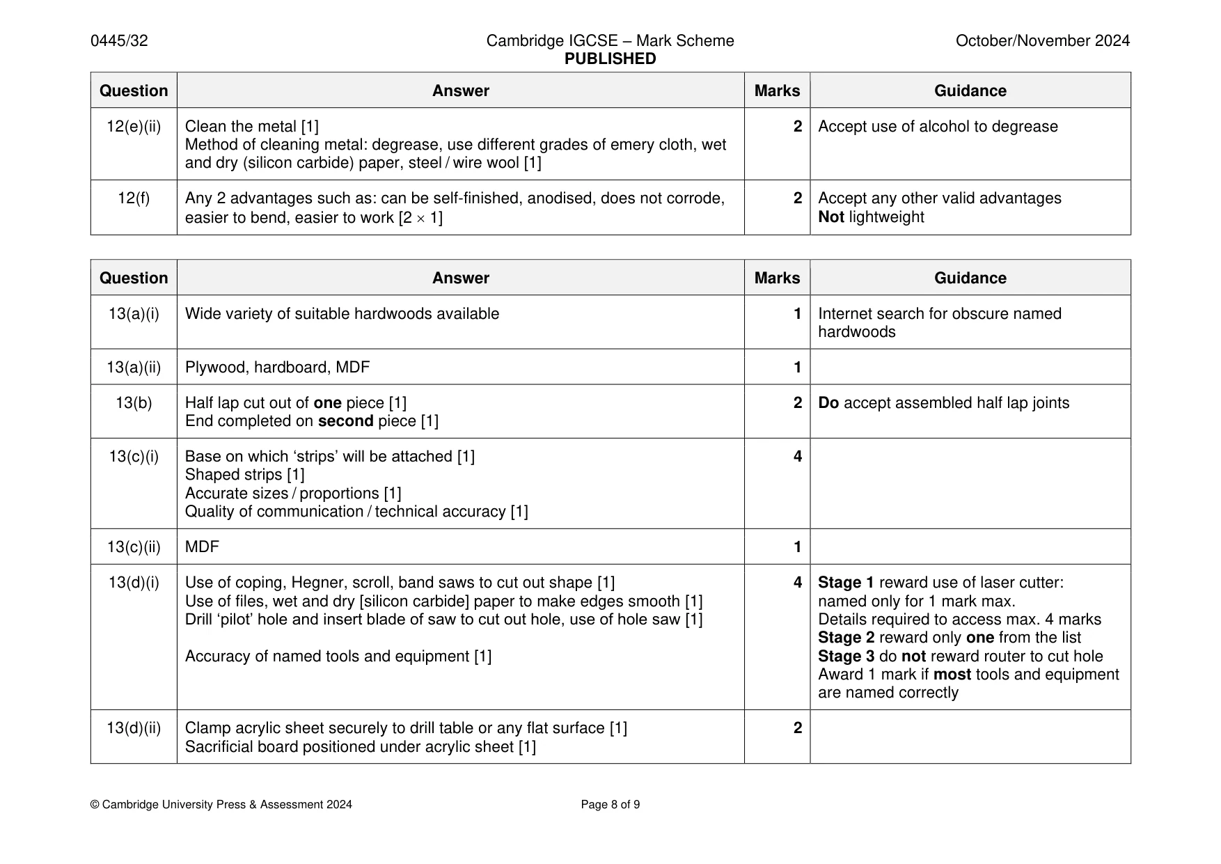
Mark scheme: 12(a)(i) To provide a guide for the tip of the drill, to prevent the drill from slipping 1 Accept any valid reasons. Not accurate 12(a)(ii) To make it easier for the Ø15 drill to produce a hole, provide a guide for the 1 Ø15 drill 12(a)(iii) Hacksaw, junior hacksaw, Hegner saw, band saw, piercing saw 1 Hegner and band saws must have metal cutting blades stated for marks 12(a)(iv) Tin snips, Hegner saw, band saw, piercing saw 1 Hegner and band saws must have metal cutting blades stated for marks 12(a)(v) Half round, round or rat tail 1 Not rounded 12(b) Sketches showing use of a former, held in a vice, mallet or hammer [3 1] 4 Do not reward heating of metal sheet Quality / clarity of communication [1] 12(c)(i) Any 3 modifications such as: enlarge view, erase / delete, fill colour, add 3 Accept any other valid modifications texture, 3D view [3 1] 12(c)(ii) Any 2 benefits such as: repetitive accuracy, speed, consistency of product, 2 Accept any other valid benefits machines can run constantly on repetitive tasks 12(d) ‘Bracket’ attached to back of coat rack [0 – 2] 6 Metal to metal bracket: soldering / brazing Allowance in bracket to fit over or on the 2 screws [0 – 2] Metal to wooden bracket: epoxy resin Named materials and constructions [0 – 2] 12(e)(i) Dip coated / plastic / powder coated finish, electroplated chrome, zinc, 1 galvanising, oil blue finish 12(e)(ii) Clean the metal [1] 2 Accept use of alcohol to degrease Method of cleaning metal: degrease, use different grades of emery cloth, wet and dry (silicon carbide) paper, steel / wire wool [1] 12(f) Any 2 advantages such as: can be self-finished, anodised, does not corrode, 2 Accept any other valid advantages easier to bend, easier to work [2 1] Not lightweight
Q13 · An incomplete design for a case to store and carry a selection of artist’s materials and…
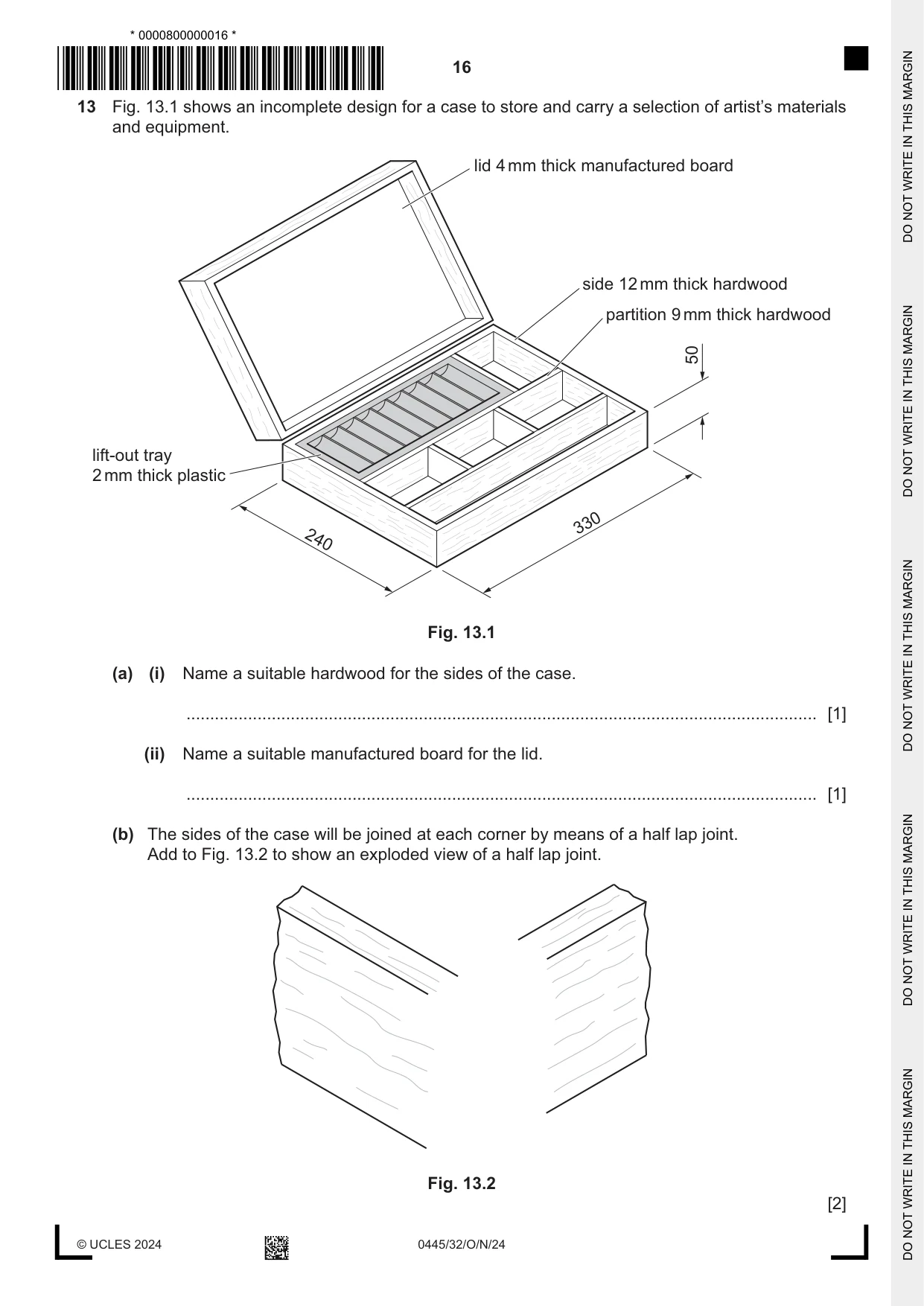
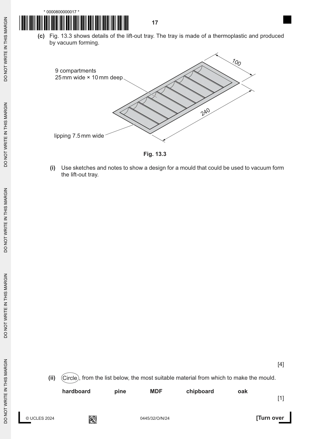
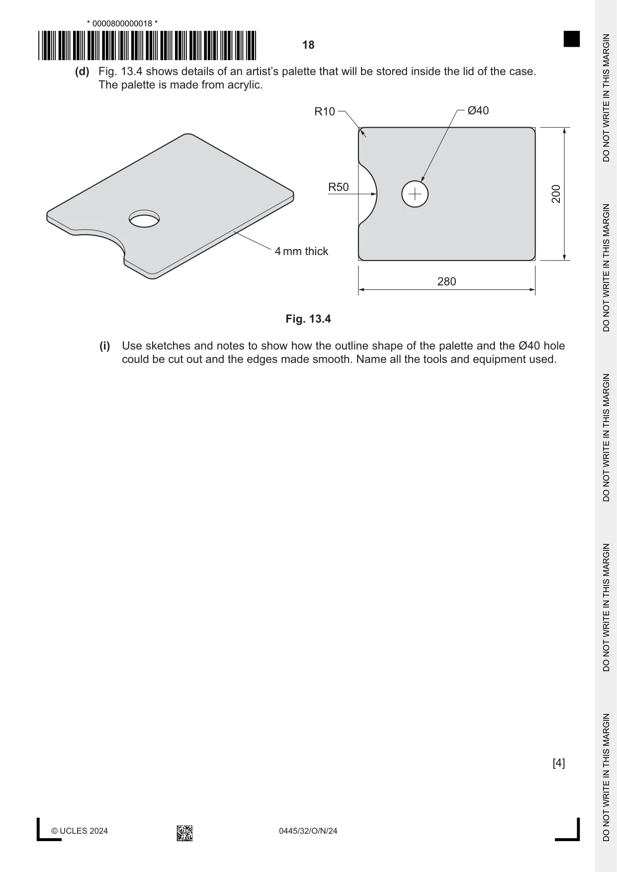
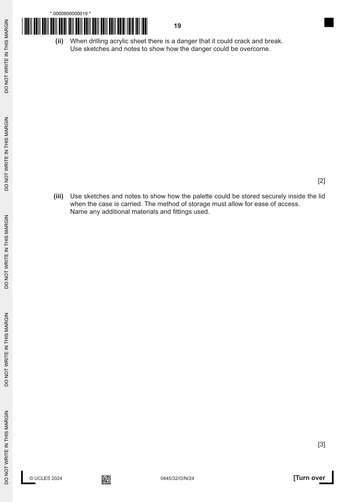
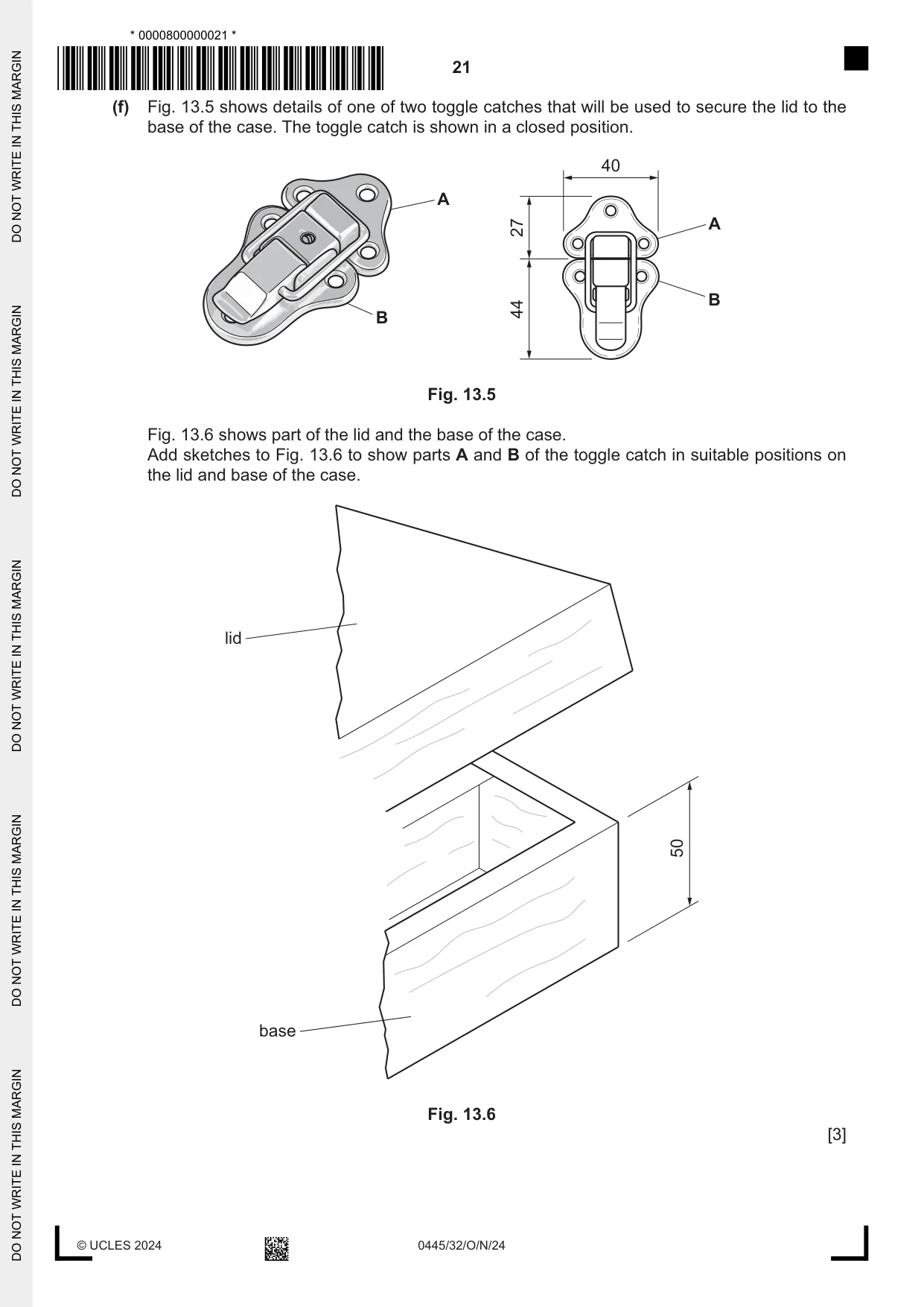
13 Fig. 13.1 shows an incomplete design for a case to store and carry a selection of artist’s materials and equipment. lid 4 mm thick manufactured board side 12 mm thick hardwood partition 9 mm thick hardwood 50 lift-out tray 2 mm thick plastic 330 240 Fig. 13.1 (a) (i) Name a suitable hardwood for the sides of the case. ..................................................................................................................................... [1] (ii) Name a suitable manufactured board for the lid. ..................................................................................................................................... [1] (b) The sides of the case will be joined at each corner by means of a half lap joint. Add to Fig. 13.2 to show an exploded view of a half lap joint. Fig. 13.2 [2] (c) Fig. 13.3 shows details of the lift-out tray. The tray is made of a thermoplastic and produced by vacuum forming. 100 9 compartments 25 mm wide × 10 mm deep 240 lipping 7.5 mm wide Fig. 13.3 (i) Use sketches and notes to show a design for a mould that could be used to vacuum form the lift-out tray. [4] (ii) Circle , from the list below, the most suitable material from which to make the mould. hardboard pine MDF chipboard oak [1] (d) Fig. 13.4 shows details of an artist’s palette that will be stored inside the lid of the case. The palette is made from acrylic. R10 Ø40 R50 200 4 mm thick 280 Fig. 13.4 (i) Use sketches and notes to show how the outline shape of the palette and the Ø40 hole could be cut out and the edges made smooth. Name all the tools and equipment used. [4]
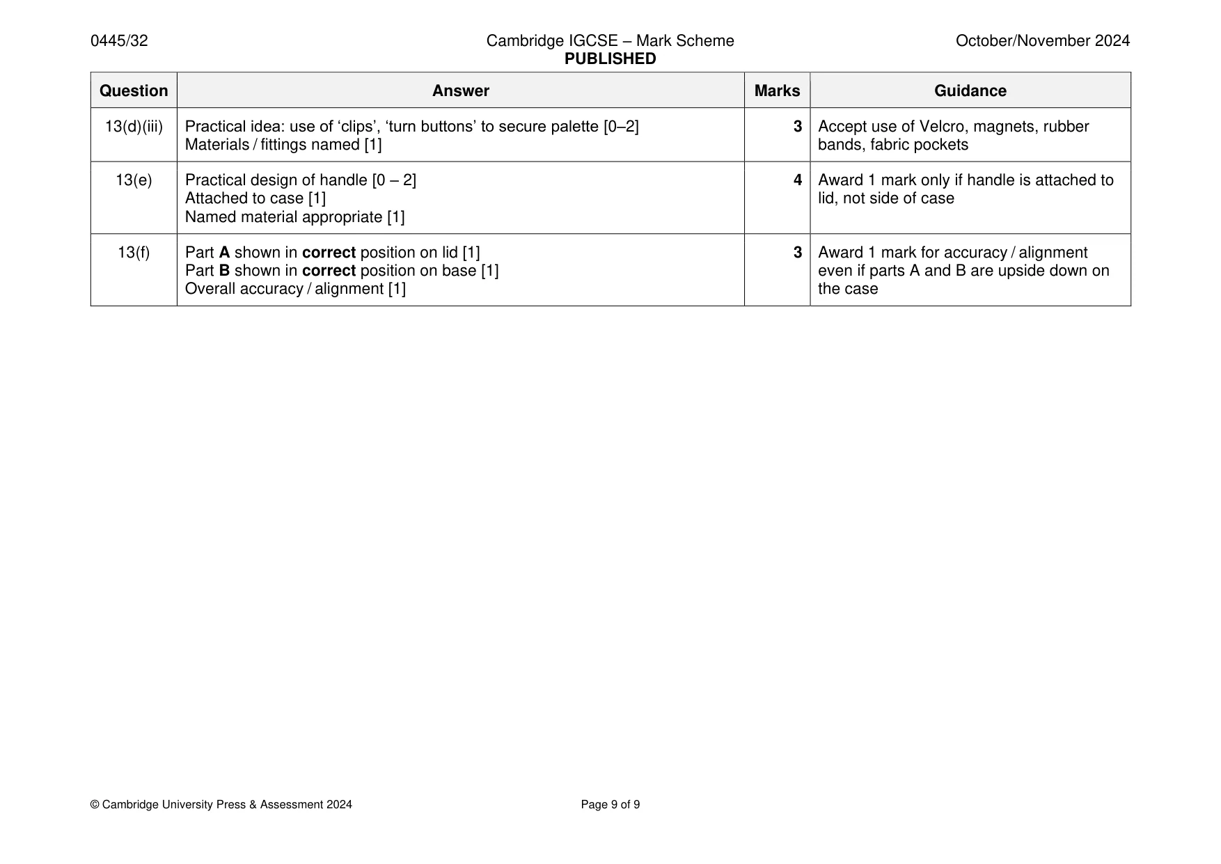
Mark scheme: 13(a)(i) Wide variety of suitable hardwoods available 1 Internet search for obscure named hardwoods 13(a)(ii) Plywood, hardboard, MDF 1 13(b) Half lap cut out of one piece [1] 2 Do accept assembled half lap joints End completed on second piece [1] 13(c)(i) Base on which ‘strips’ will be attached [1] 4 Shaped strips [1] Accurate sizes / proportions [1] Quality of communication / technical accuracy [1] 13(c)(ii) MDF 1 13(d)(i) Use of coping, Hegner, scroll, band saws to cut out shape [1] 4 Stage 1 reward use of laser cutter: Use of files, wet and dry [silicon carbide] paper to make edges smooth [1] named only for 1 mark max. Drill ‘pilot’ hole and insert blade of saw to cut out hole, use of hole saw [1] Details required to access max. 4 marks Stage 2 reward only one from the list Accuracy of named tools and equipment [1] Stage 3 do not reward router to cut hole Award 1 mark if most tools and equipment are named correctly 13(d)(ii) Clamp acrylic sheet securely to drill table or any flat surface [1] 2 Sacrificial board positioned under acrylic sheet [1] 13(d)(iii) Practical idea: use of ‘clips’, ‘turn buttons’ to secure palette [0–2] 3 Accept use of Velcro, magnets, rubber Materials / fittings named [1] bands, fabric pockets 13(e) Practical design of handle [0 – 2] 4 Award 1 mark only if handle is attached to Attached to case [1] lid, not side of case Named material appropriate [1] 13(f) Part A shown in correct position on lid [1] 3 Award 1 mark for accuracy / alignment Part B shown in correct position on base [1] even if parts A and B are upside down on Overall accuracy / alignment [1] the case
What was in this paper
The subtopics covered by these 13 questions, and how many questions each got. Open one in a new tab to see every Cambridge question on it.
What you needed in this session
Cambridge’s own grade thresholds for 2024 Oct/Nov, Paper 3 · Variant 2. A higher threshold means an easier paper — the bar moves with how the cohort did.