Cambridge IGCSE Design and Technology 0445 — 2024 May/June Paper 3 · Variant 3
0445/33/M/J/24 · 13 questions · 50 marks · 60 min
The question paper and its mark scheme, free to read here and free to download. This is Cambridge’s own paper, exactly as it was sat.
Question paper24 pages
Mark scheme9 pages
Answers below. Sit the paper first if you are practising.
Questions as text
Question 1
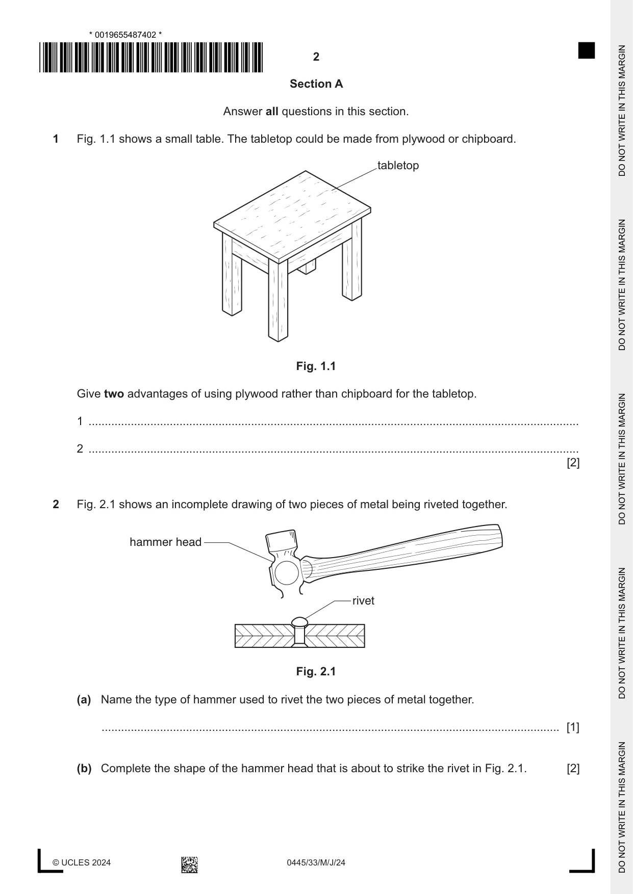
1 Fig. 1.1 shows a small table. The tabletop could be made from plywood or chipboard. tabletop Fig. 1.1 Give two advantages of using plywood rather than chipboard for the tabletop. 1 ....................................................................................................................................................... 2 ....................................................................................................................................................... [2]
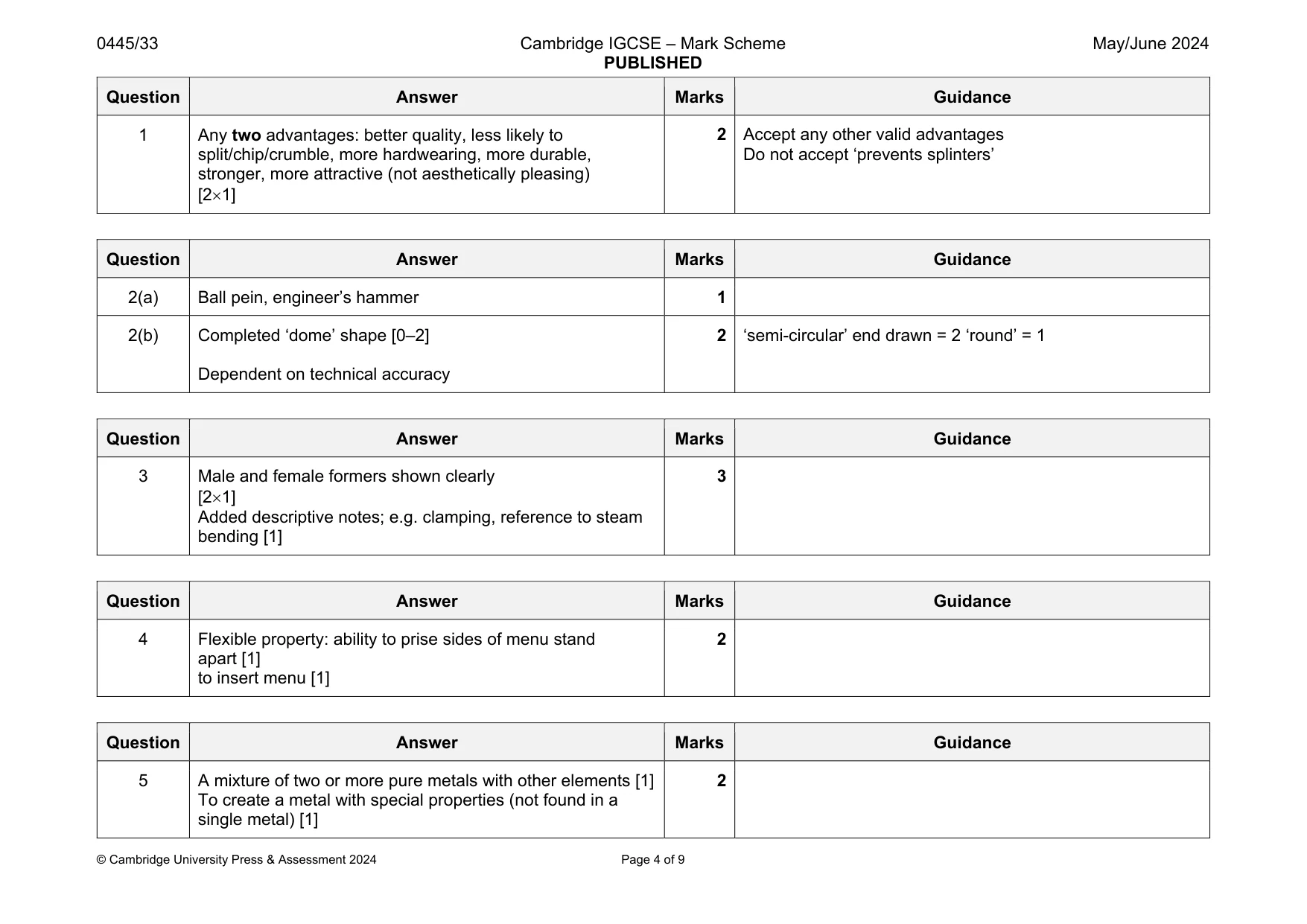
Mark scheme: 1 Any two advantages: better quality, less likely to split/chip/crumble, more hardwearing, more durable, stronger, more attractive (not aesthetically pleasing) [21] Do not accept ‘prevents splinters’
Q2 · An incomplete drawing of two pieces of metal being riveted together
2 Fig. 2.1 shows an incomplete drawing of two pieces of metal being riveted together. hammer head rivet Fig. 2.1 (a) Name the type of hammer used to rivet the two pieces of metal together. ............................................................................................................................................. [1] (b) Complete the shape of the hammer head that is about to strike the rivet in Fig. 2.1. [2]
Mark scheme: 2(a) Ball pein, engineer’s hammer 1 2(b) Completed ‘dome’ shape [0–2] Dependent on technical accuracy 2 ‘semi-circular’ end drawn = 2 ‘round’ = 1
Q3 · Details of a length of 8 mm thick hardwood that has been bent to shape
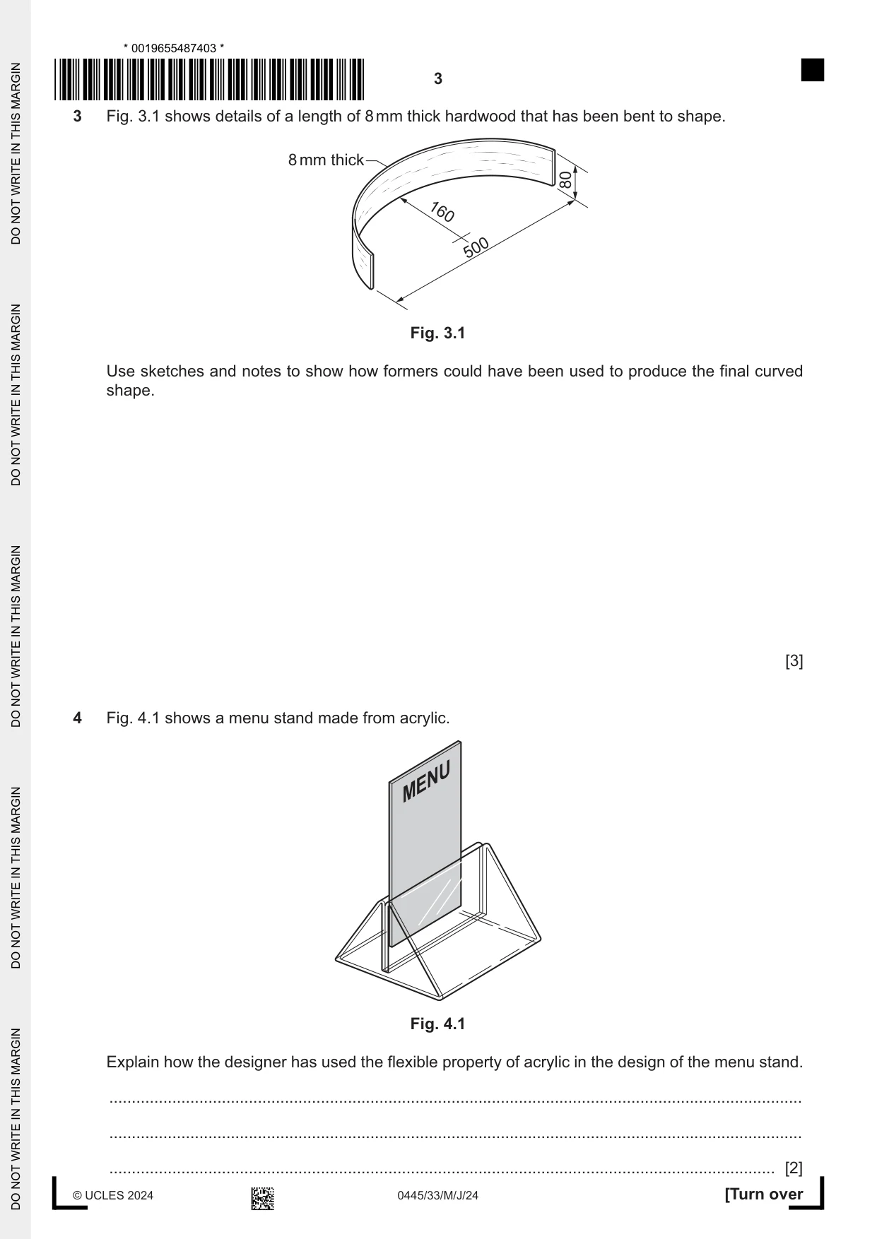
3 Fig. 3.1 shows details of a length of 8 mm thick hardwood that has been bent to shape. 8 mm thick 80 160 500 Fig. 3.1 Use sketches and notes to show how formers could have been used to produce the final curved shape. [3]
Mark scheme: 3 Male and female formers shown clearly [21] Added descriptive notes; e.g. clamping, reference to steam bending [1] 3
Q4 · A menu stand made from acrylic
4 Fig. 4.1 shows a menu stand made from acrylic. MENU Fig. 4.1 Explain how the designer has used the flexible property of acrylic in the design of the menu stand. .......................................................................................................................................................... .......................................................................................................................................................... .................................................................................................................................................... [2]
Mark scheme: 4 Flexible property: ability to prise sides of menu stand apart [1] to insert menu [1] 2
Q5 · Explain the term ‘alloy’
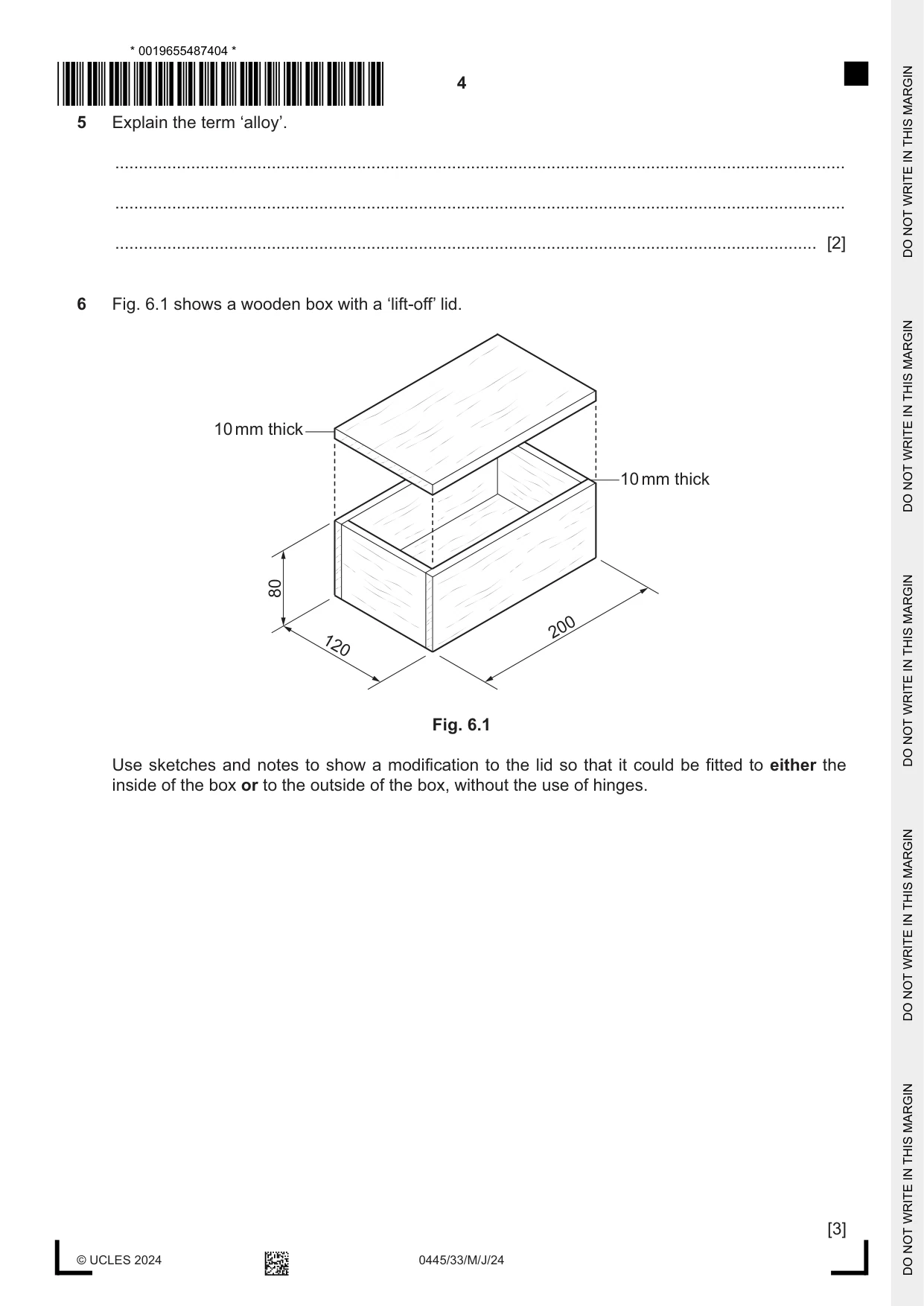
5 Explain the term ‘alloy’. .......................................................................................................................................................... .......................................................................................................................................................... .................................................................................................................................................... [2]
Mark scheme: 5 A mixture of two or more pure metals with other elements [1] To create a metal with special properties (not found in a single metal) [1]
Q6 · A wooden box with a ‘lift-off’ lid
6 Fig. 6.1 shows a wooden box with a ‘lift-off’ lid. 10 mm thick 10 mm thick 80 200 120 Fig. 6.1 Use sketches and notes to show a modification to the lid so that it could be fitted to either the inside of the box or to the outside of the box, without the use of hinges. [3]
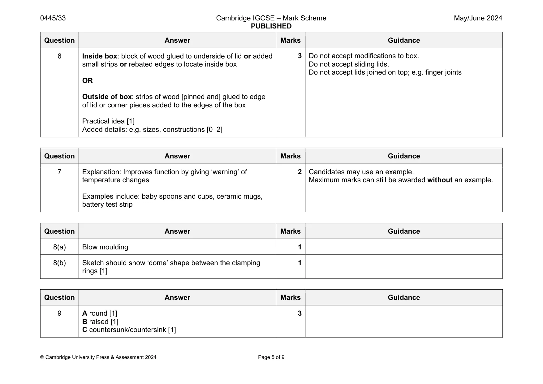
Mark scheme: 6 Inside box: block of wood glued to underside of lid or added small strips or rebated edges to locate inside box OR Outside of box: strips of wood [pinned and] glued to edge of lid or corner pieces added to the edges of the box Practical idea [1] Added details: e.g. sizes, constructions [0–2] Do not accept sliding lids. Do not accept lids joined on top; e.g. finger joints
Q7 · Thermochromic materials change colour at specific temperatures
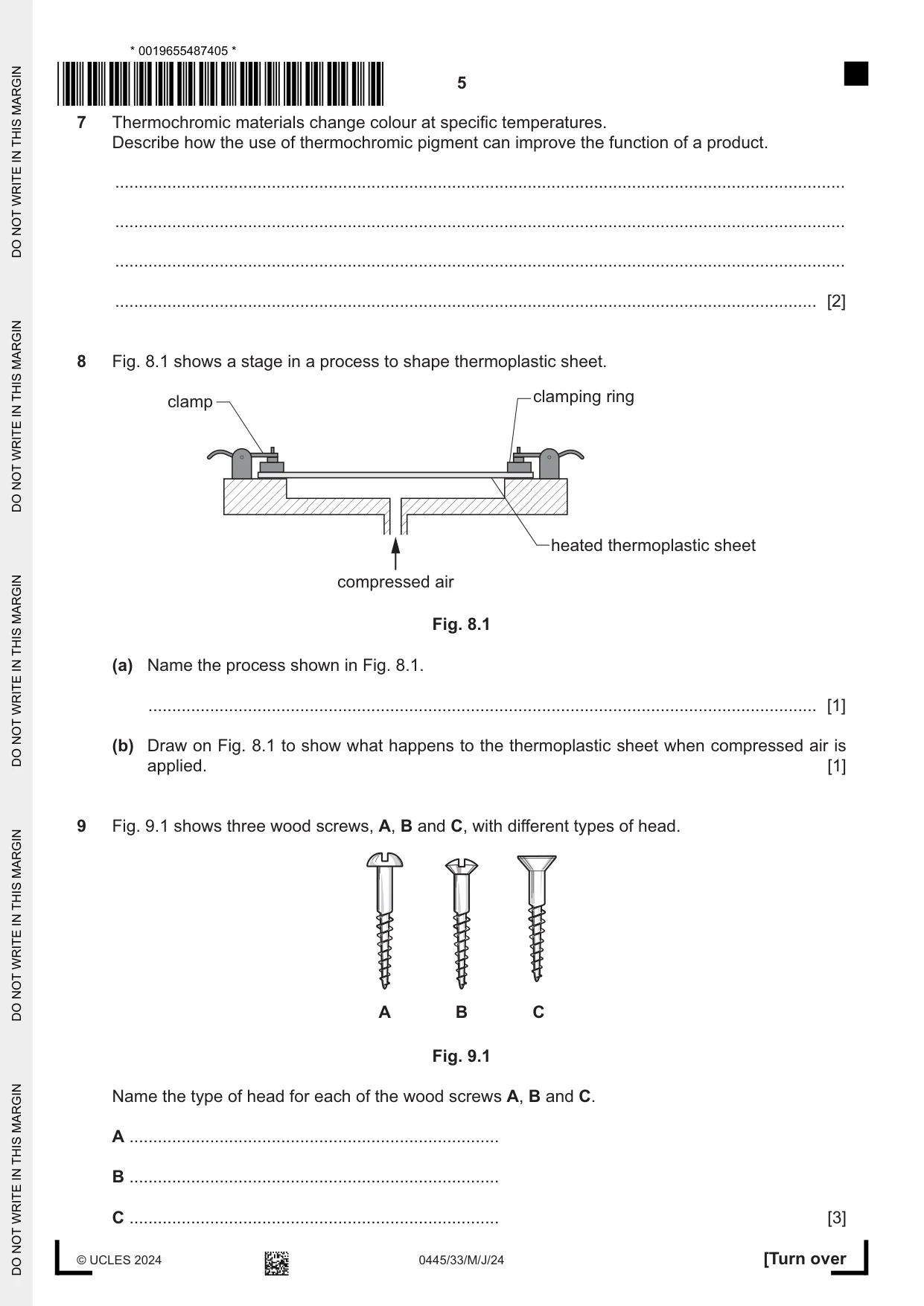
7 Thermochromic materials change colour at specific temperatures. Describe how the use of thermochromic pigment can improve the function of a product. .......................................................................................................................................................... .......................................................................................................................................................... .......................................................................................................................................................... .................................................................................................................................................... [2]
Mark scheme: 7 Explanation: Improves function by giving ‘warning’ of temperature changes Examples include: baby spoons and cups, ceramic mugs, battery test strip Maximum marks can still be awarded without an example.
Q8 · A stage in a process to shape thermoplastic sheet
8 Fig. 8.1 shows a stage in a process to shape thermoplastic sheet. clamping ring clamp heated thermoplastic sheet compressed air Fig. 8.1 (a) Name the process shown in Fig. 8.1. ............................................................................................................................................. [1] (b) Draw on Fig. 8.1 to show what happens to the thermoplastic sheet when compressed air is applied. [1]
Mark scheme: 8(a) Blow moulding 1 8(b) Sketch should show ‘dome’ shape between the clamping rings [1] 1
Q9 · Three wood screws, A, B and C, with different types of head
9 Fig. 9.1 shows three wood screws, A, B and C, with different types of head. A B C Fig. 9.1 Name the type of head for each of the wood screws A, B and C. A .............................................................................. B .............................................................................. C .............................................................................. [3]
Mark scheme: 9 A round [1] B raised [1] C countersunk/countersink [1]
Q10 · A piercing saw that will be used to cut out the curved shape in a piece of 1 mm thick…
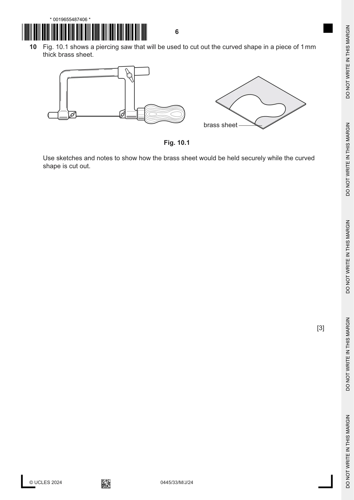
10 Fig. 10.1 shows a piercing saw that will be used to cut out the curved shape in a piece of 1 mm thick brass sheet. brass sheet Fig. 10.1 Use sketches and notes to show how the brass sheet would be held securely while the curved shape is cut out. [3]
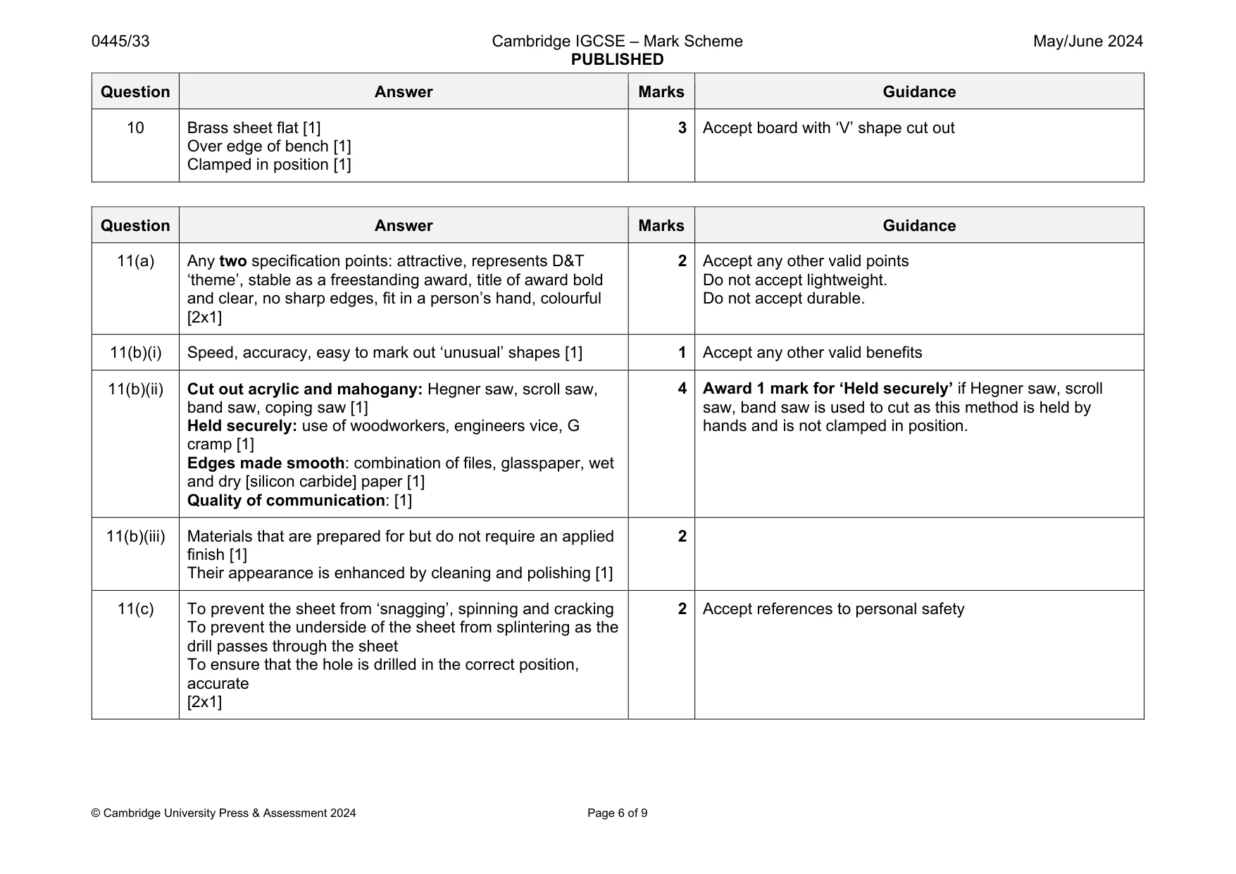
Mark scheme: 10 Brass sheet flat [1] Over edge of bench [1] Clamped in position [1] 3 Accept board with ‘V’ shape cut out
Q11 · Views of an incomplete design for a trophy
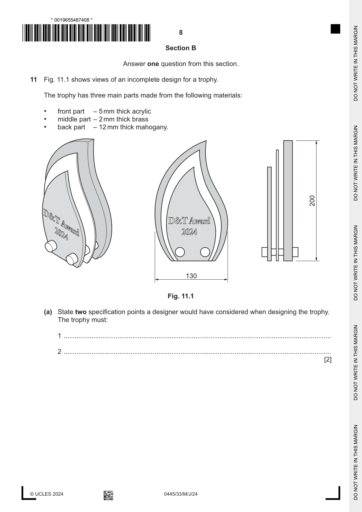
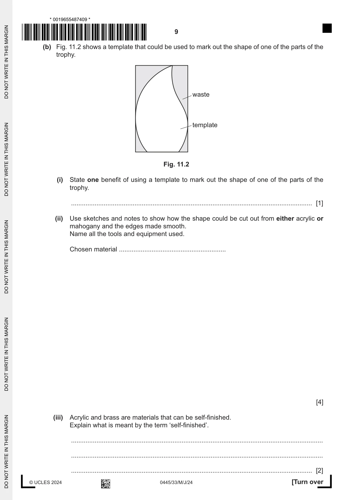
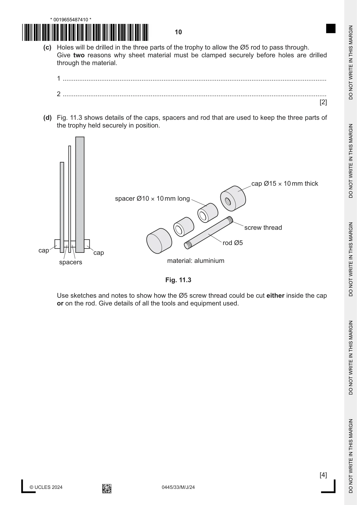
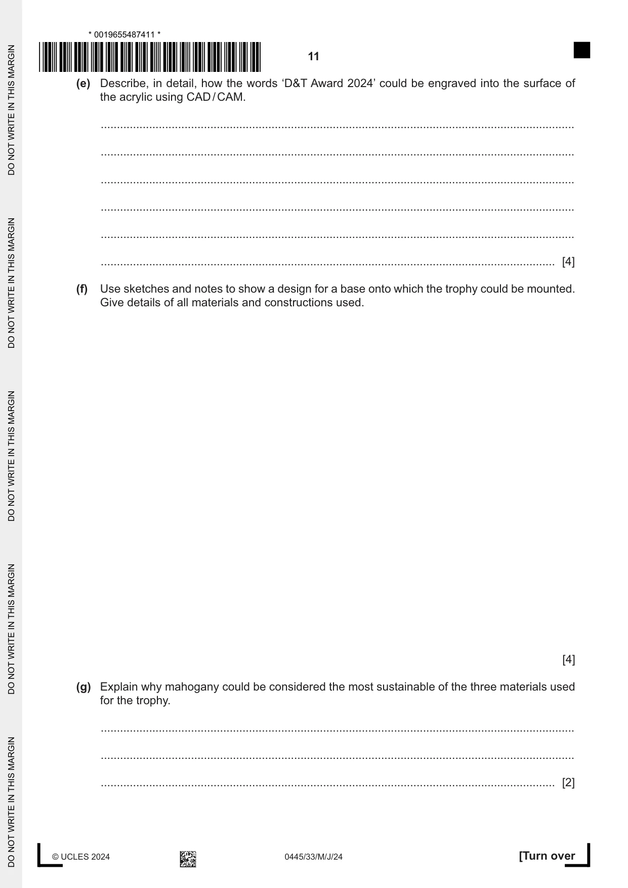
11 Fig. 11.1 shows views of an incomplete design for a trophy. The trophy has three main parts made from the following materials: • front part – 5 mm thick acrylic • middle part – 2 mm thick brass • back part – 12 mm thick mahogany. 200 D&T D&T Award 2024 Award 2024 130 Fig. 11.1 (a) State two specification points a designer would have considered when designing the trophy. The trophy must: 1 ................................................................................................................................................ 2 ................................................................................................................................................ [2] (b) Fig. 11.2 shows a template that could be used to mark out the shape of one of the parts of the trophy. waste template Fig. 11.2 (i) State one benefit of using a template to mark out the shape of one of the parts of the trophy. ..................................................................................................................................... [1] (ii) Use sketches and notes to show how the shape could be cut out from either acrylic or mahogany and the edges made smooth. Name all the tools and equipment used. Chosen material ........................................................... [4] (iii) Acrylic and brass are materials that can be self-finished. Explain what is meant by the term ‘self-finished’. ........................................................................................................................................... ........................................................................................................................................... ..................................................................................................................................... [2] (c) Holes will be drilled in the three parts of the trophy to allow the Ø5 rod to pass through. Give two reasons why sheet material must be clamped securely before holes are drilled through the material. 1 ................................................................................................................................................ 2 ................................................................................................................................................ [2] (d) Fig. 11.3 shows details of the caps, spacers and rod that are used to keep the three parts of the trophy held securely in position. cap Ø15 × 10 mm thick spacer Ø10 × 10 mm long screw thread rod Ø5 cap cap spacers material: aluminium Fig. 11.3 Use sketches and notes to show how the Ø5 screw thread could be cut either inside the cap or on the rod. Give details of all the tools and equipment used. [4] (e) Describe, in detail, how the words ‘D&T Award 2024’ could be engraved into the surface of the acrylic using CAD / CAM. ................................................................................................................................................... ................................................................................................................................................... ................................................................................................................................................... ................................................................................................................................................... ................................................................................................................................................... ............................................................................................................................................. [4] (f) Use sketches and notes to show a design for a base onto which the trophy could be mounted. Give details of all materials and constructions used. [4] (g) Explain why mahogany could be considered the most sustainable of the three materials used for the trophy. ................................................................................................................................................... ................................................................................................................................................... ............................................................................................................................................. [2]
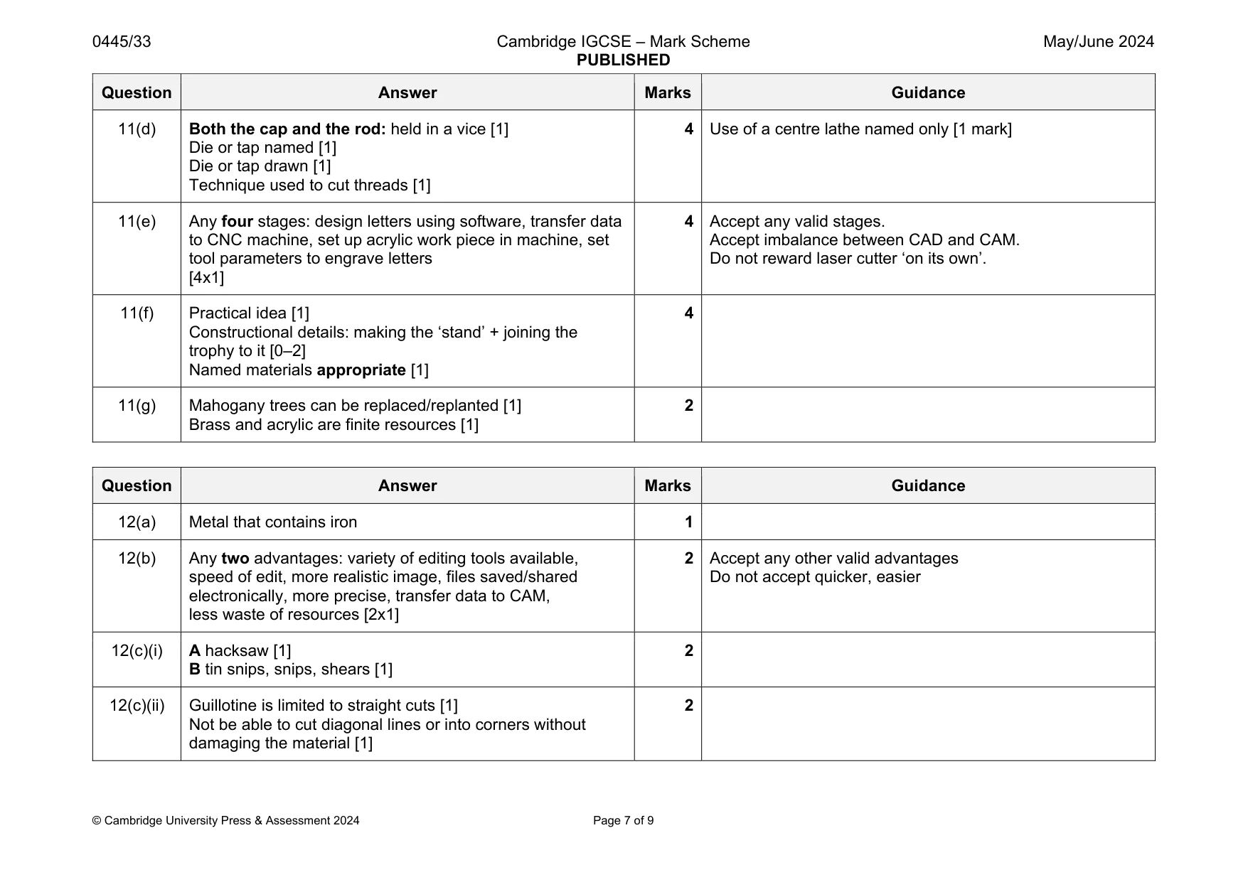
Mark scheme: 11(a) Any two specification points: attractive, represents D&T ‘theme’, stable as a freestanding award, title of award bold and clear, no sharp edges, fit in a person’s hand, colourful [2x1] 2 Accept any other valid points Do not accept lightweight. Do not accept durable. 11(b)(i) Speed, accuracy, easy to mark out ‘unusual’ shapes [1] 1 Accept any other valid benefits 11(b)(ii) Cut out acrylic and mahogany: Hegner saw, scroll saw, band saw, coping saw [1] Held securely: use of woodworkers, engineers vice, G cramp [1] Edges made smooth: combination of files, glasspaper, wet and dry [silicon carbide] paper [1] Quality of communication: [1] 4 Award 1 mark for ‘Held securely’ if Hegner saw, scroll saw, band saw is used to cut as this method is held by hands and is not clamped in position. 11(b)(iii) Materials that are prepared for but do not require an applied finish [1] Their appearance is enhanced by cleaning and polishing [1] 2 11(c) To prevent the sheet from ‘snagging’, spinning and cracking To prevent the underside of the sheet from splintering as the drill passes through the sheet To ensure that the hole is drilled in the correct position, accurate [2x1] 2 Accept references to personal safety Question Answer Marks Guidance 11(d) Both the cap and the rod: held in a vice [1] Die or tap named [1] Die or tap drawn [1] Technique used to cut threads [1] 4 Use of a centre lathe named only [1 mark] 11(e) Any four stages: design letters using software, transfer data to CNC machine, set up acrylic work piece in machine, set tool parameters to engrave letters [4x1] 4 Accept any valid stages. Accept imbalance between CAD and CAM. Do not reward laser cutter ‘on its own’. 11(f) Practical idea [1] Constructional details: making the ‘stand’ + joining the trophy to it [0–2] Named materials appropriate [1] 4 11(g) Mahogany trees can be replaced/replanted [1] Brass and acrylic are finite resources [1] 2
Q12 · An incomplete design for a bird feeder made from 1.5 mm thick mild steel sheet
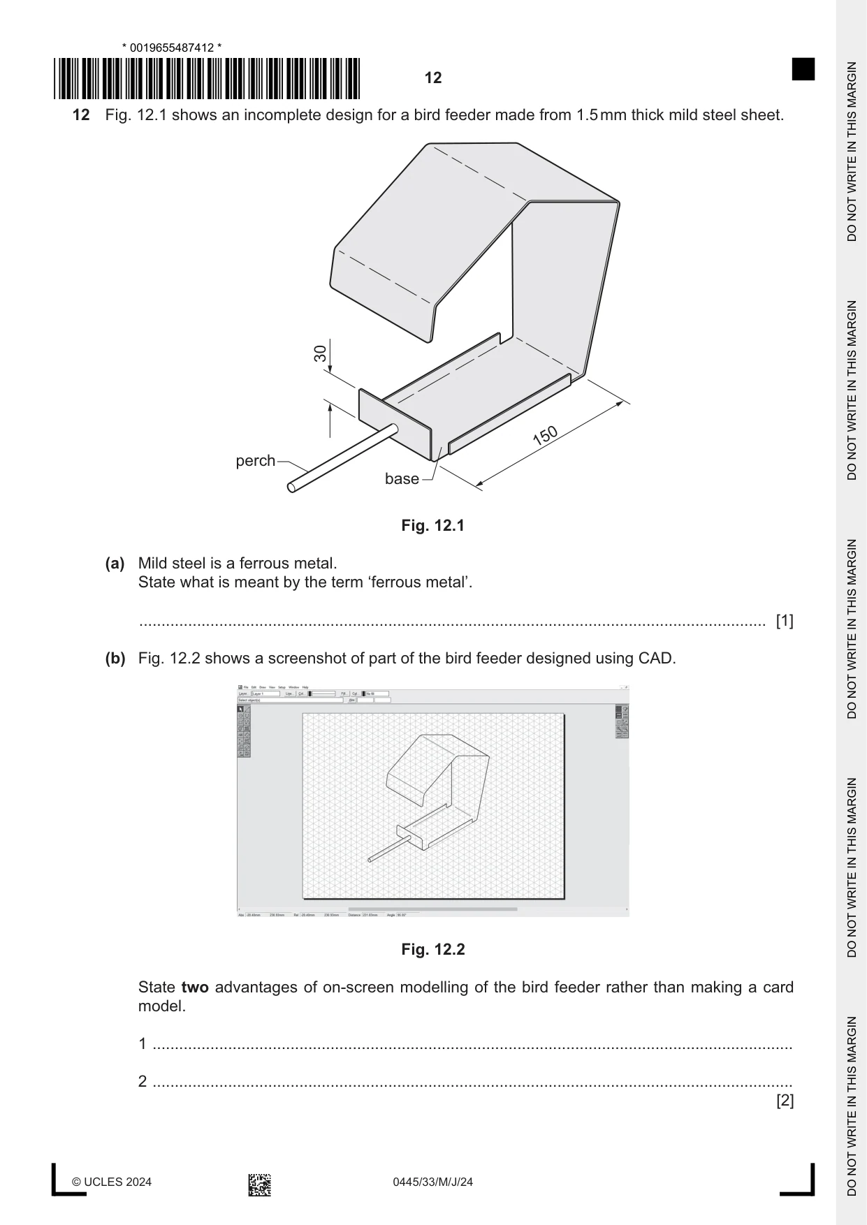
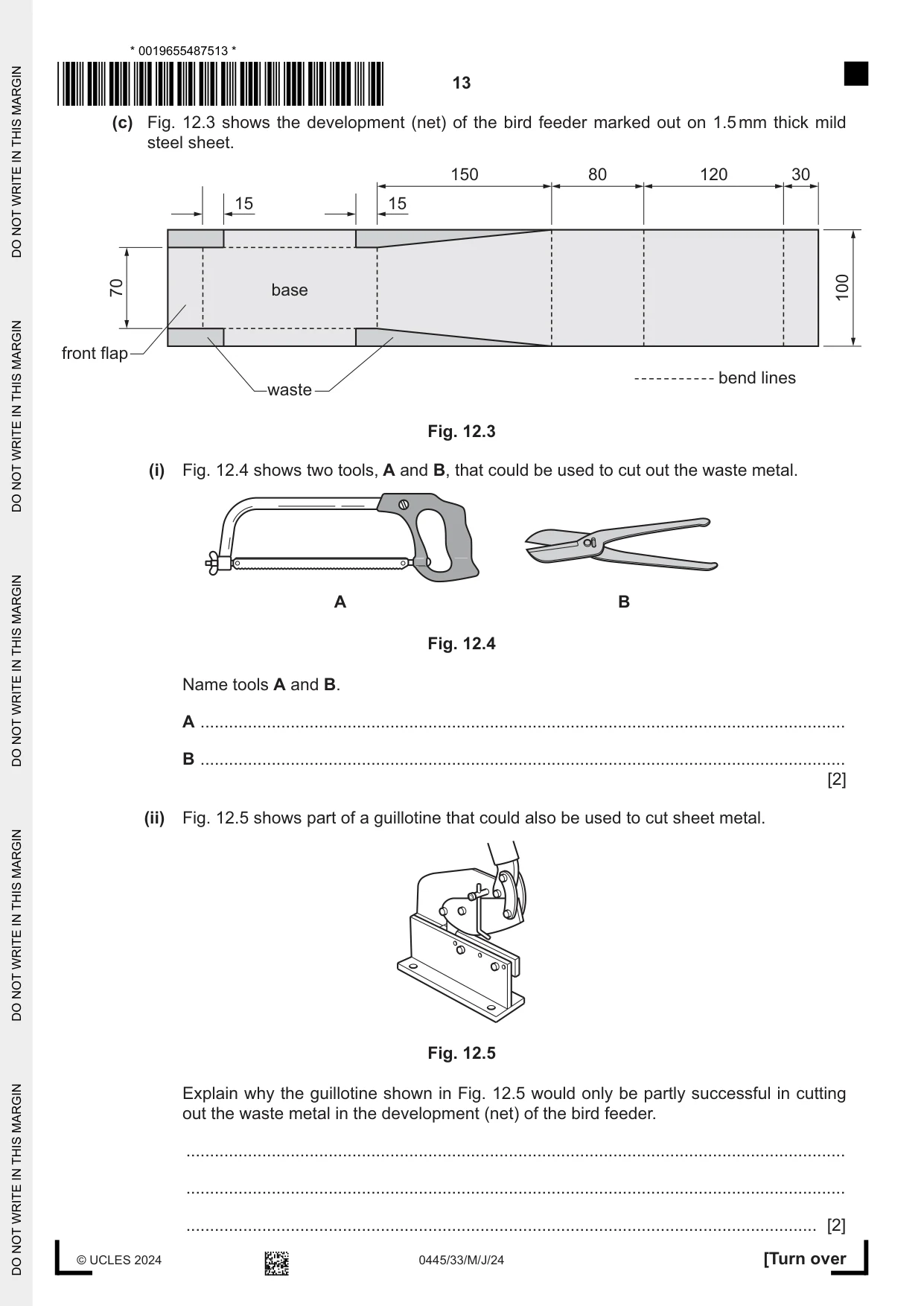
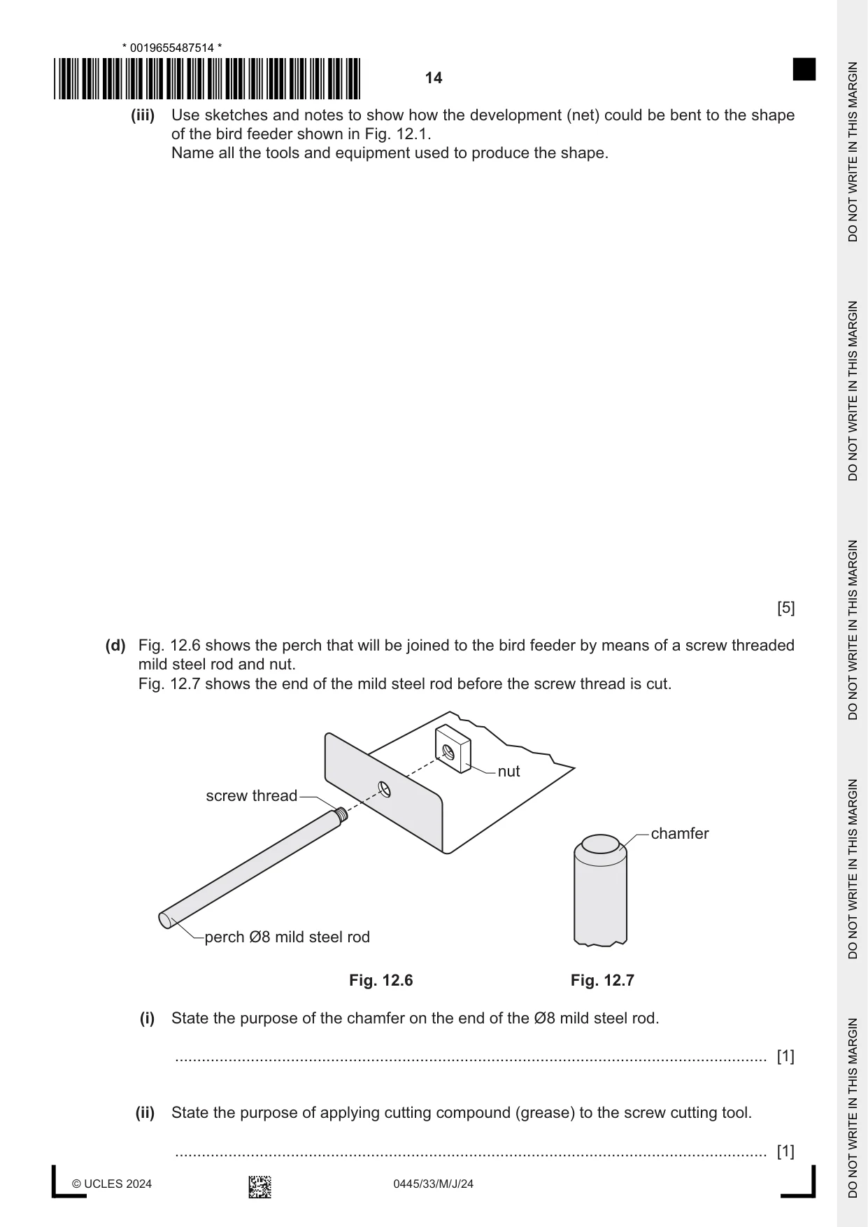
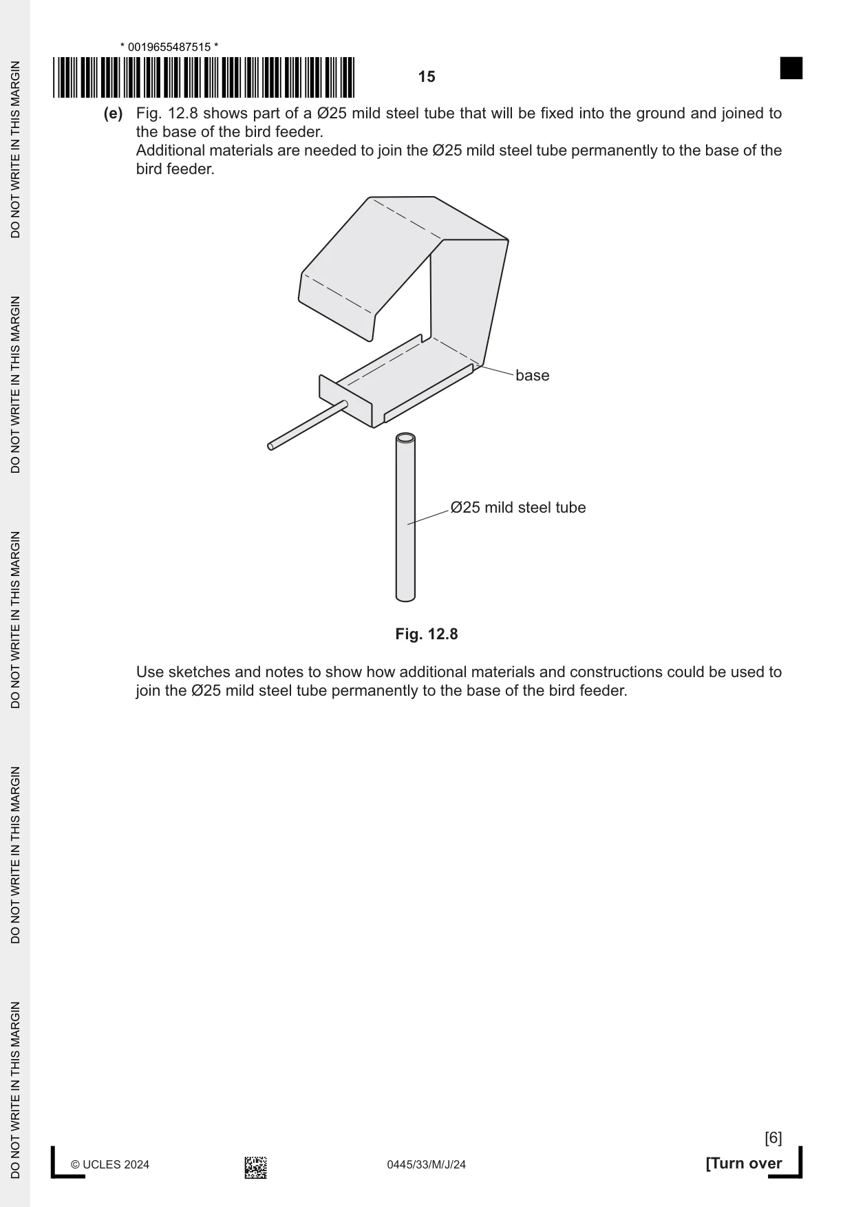
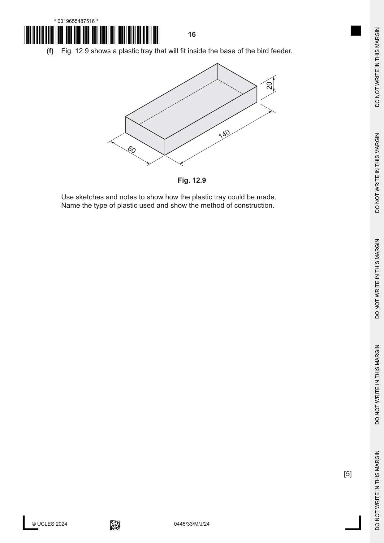
12 Fig. 12.1 shows an incomplete design for a bird feeder made from 1.5 mm thick mild steel sheet. 30 150 perch base Fig. 12.1 (a) Mild steel is a ferrous metal. State what is meant by the term ‘ferrous metal’. ............................................................................................................................................. [1] (b) Fig. 12.2 shows a screenshot of part of the bird feeder designed using CAD. Fig. 12.2 State two advantages of on-screen modelling of the bird feeder rather than making a card model. 1 ................................................................................................................................................ 2 ................................................................................................................................................ [2] (c) Fig. 12.3 shows the development (net) of the bird feeder marked out on 1.5 mm thick mild steel sheet. 150 80 120 30 15 15 70 base 100 front flap bend lines waste Fig. 12.3 (i) Fig. 12.4 shows two tools, A and B, that could be used to cut out the waste metal. A B Fig. 12.4 Name tools A and B. A ........................................................................................................................................ B ........................................................................................................................................ [2] (ii) Fig. 12.5 shows part of a guillotine that could also be used to cut sheet metal. Fig. 12.5 Explain why the guillotine shown in Fig. 12.5 would only be partly successful in cutting out the waste metal in the development (net) of the bird feeder. ........................................................................................................................................... ........................................................................................................................................... ..................................................................................................................................... [2] (iii) Use sketches and notes to show how the development (net) could be bent to the shape of the bird feeder shown in Fig. 12.1. Name all the tools and equipment used to produce the shape. [5] (d) Fig. 12.6 shows the perch that will be joined to the bird feeder by means of a screw threaded mild steel rod and nut. Fig. 12.7 shows the end of the mild steel rod before the screw thread is cut. nut screw thread chamfer perch Ø8 mild steel rod Fig. 12.6 Fig. 12.7 (i) State the purpose of the chamfer on the end of the Ø8 mild steel rod. ..................................................................................................................................... [1] (ii) State the purpose of applying cutting compound (grease) to the screw cutting tool. ..................................................................................................................................... [1] (e) Fig. 12.8 shows part of a Ø25 mild steel tube that will be fixed into the ground and joined to the base of the bird feeder. Additional materials are needed to join the Ø25 mild steel tube permanently to the base of the bird feeder. base Ø25 mild steel tube Fig. 12.8 Use sketches and notes to show how additional materials and constructions could be used to join the Ø25 mild steel tube permanently to the base of the bird feeder. [6] (f) Fig. 12.9 shows a plastic tray that will fit inside the base of the bird feeder. 20 140 60 Fig. 12.9 Use sketches and notes to show how the plastic tray could be made. Name the type of plastic used and show the method of construction. [5]
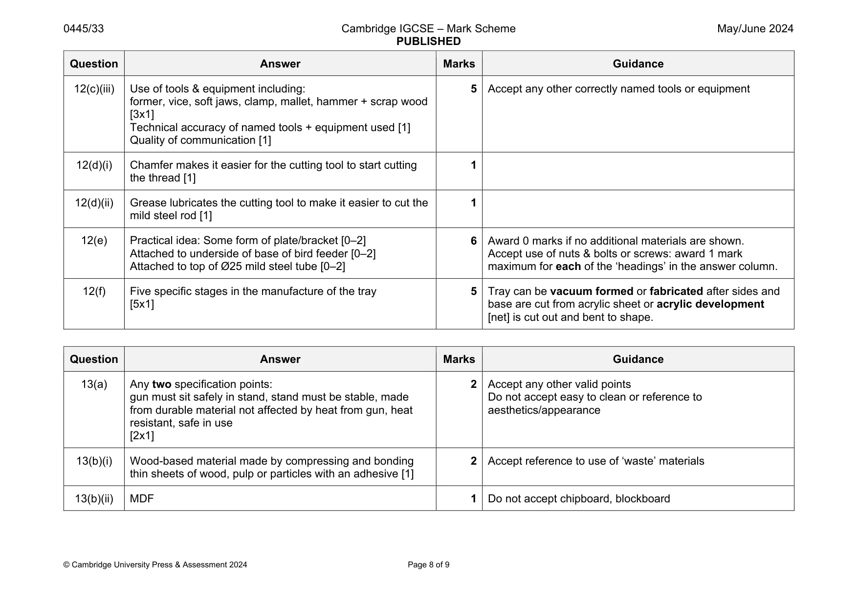
Mark scheme: 12(a) Metal that contains iron 1 12(b) Any two advantages: variety of editing tools available, speed of edit, more realistic image, files saved/shared electronically, more precise, transfer data to CAM, less waste of resources [2x1] 2 Accept any other valid advantages Do not accept quicker, easier 12(c)(i) A hacksaw [1] B tin snips, snips, shears [1] 2 12(c)(ii) Guillotine is limited to straight cuts [1] Not be able to cut diagonal lines or into corners without damaging the material [1] 2 Question Answer Marks Guidance 12(c)(iii) Use of tools & equipment including: former, vice, soft jaws, clamp, mallet, hammer + scrap wood [3x1] Technical accuracy of named tools + equipment used [1] Quality of communication [1] 5 Accept any other correctly named tools or equipment 12(d)(i) Chamfer makes it easier for the cutting tool to start cutting the thread [1] 1 12(d)(ii) Grease lubricates the cutting tool to make it easier to cut the mild steel rod [1] 1 12(e) Practical idea: Some form of plate/bracket [0–2] Attached to underside of base of bird feeder [0–2] Attached to top of Ø25 mild steel tube [0–2] 6 Award 0 marks if no additional materials are shown. Accept use of nuts & bolts or screws: award 1 mark maximum for each of the ‘headings’ in the answer column. 12(f) Five specific stages in the manufacture of the tray [5x1] 5 Tray can be vacuum formed or fabricated after sides and base are cut from acrylic sheet or acrylic development [net] is cut out and bent to shape.
Q13 · A design for a stand for a hot melt glue gun
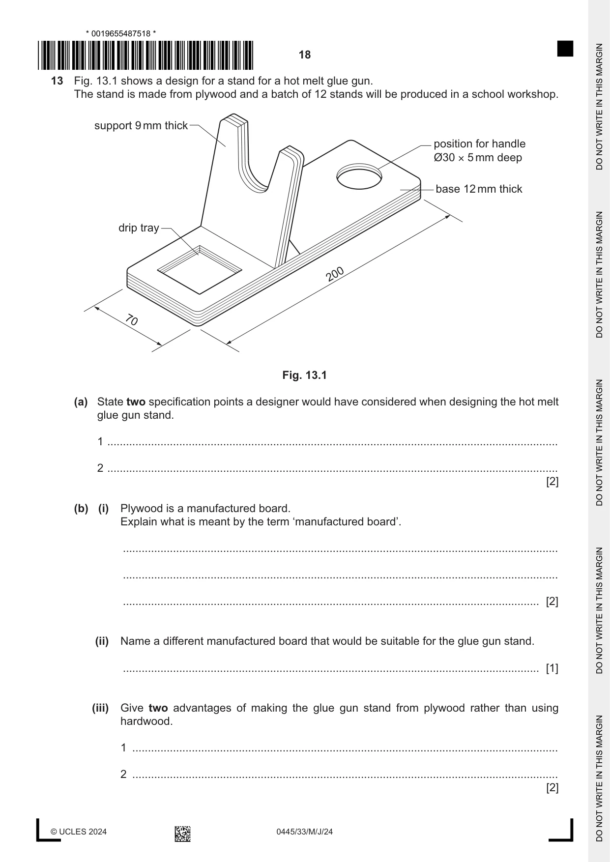
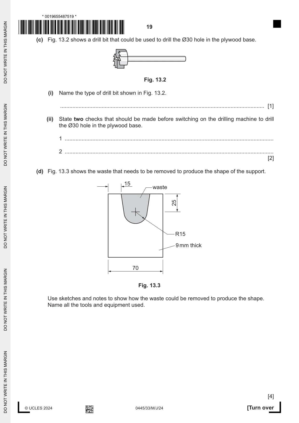
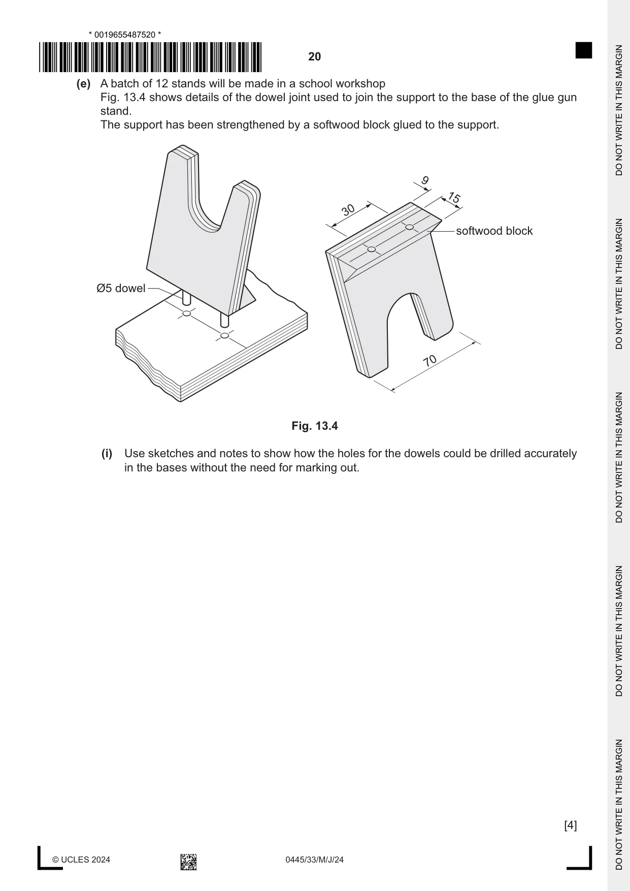
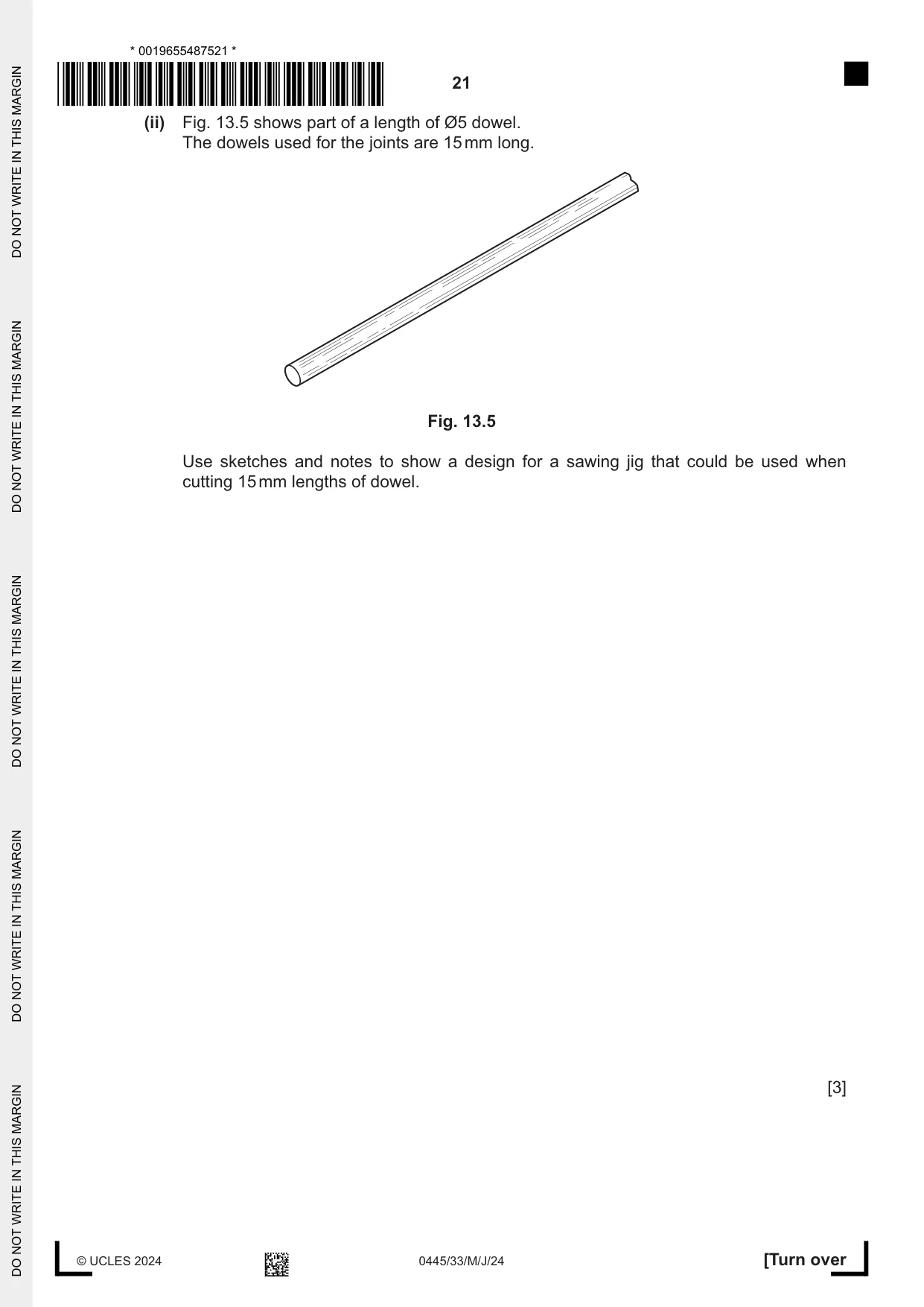
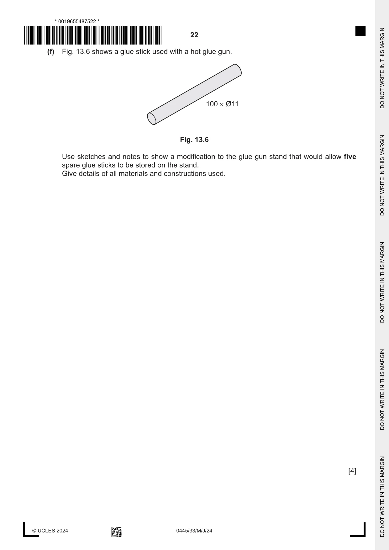
13 Fig. 13.1 shows a design for a stand for a hot melt glue gun. The stand is made from plywood and a batch of 12 stands will be produced in a school workshop. support 9 mm thick position for handle Ø30 × 5 mm deep base 12 mm thick drip tray 200 70 Fig. 13.1 (a) State two specification points a designer would have considered when designing the hot melt glue gun stand. 1 ................................................................................................................................................ 2 ................................................................................................................................................ [2] (b) (i) Plywood is a manufactured board. Explain what is meant by the term ‘manufactured board’. ........................................................................................................................................... ........................................................................................................................................... ..................................................................................................................................... [2] (ii) Name a different manufactured board that would be suitable for the glue gun stand. ..................................................................................................................................... [1] (iii) Give two advantages of making the glue gun stand from plywood rather than using hardwood. 1 ........................................................................................................................................ 2 ........................................................................................................................................ [2] (c) Fig. 13.2 shows a drill bit that could be used to drill the Ø30 hole in the plywood base. Fig. 13.2 (i) Name the type of drill bit shown in Fig. 13.2. ..................................................................................................................................... [1] (ii) State two checks that should be made before switching on the drilling machine to drill the Ø30 hole in the plywood base. 1 ........................................................................................................................................ 2 ........................................................................................................................................ [2] (d) Fig. 13.3 shows the waste that needs to be removed to produce the shape of the support. 15 waste 25 R15 9 mm thick 70 Fig. 13.3 Use sketches and notes to show how the waste could be removed to produce the shape. Name all the tools and equipment used. [4] (e) A batch of 12 stands will be made in a school workshop Fig. 13.4 shows details of the dowel joint used to join the support to the base of the glue gun stand. The support has been strengthened by a softwood block glued to the support. 9 15 30 softwood block Ø5 dowel 70 Fig. 13.4 (i) Use sketches and notes to show how the holes for the dowels could be drilled accurately in the bases without the need for marking out. [4]
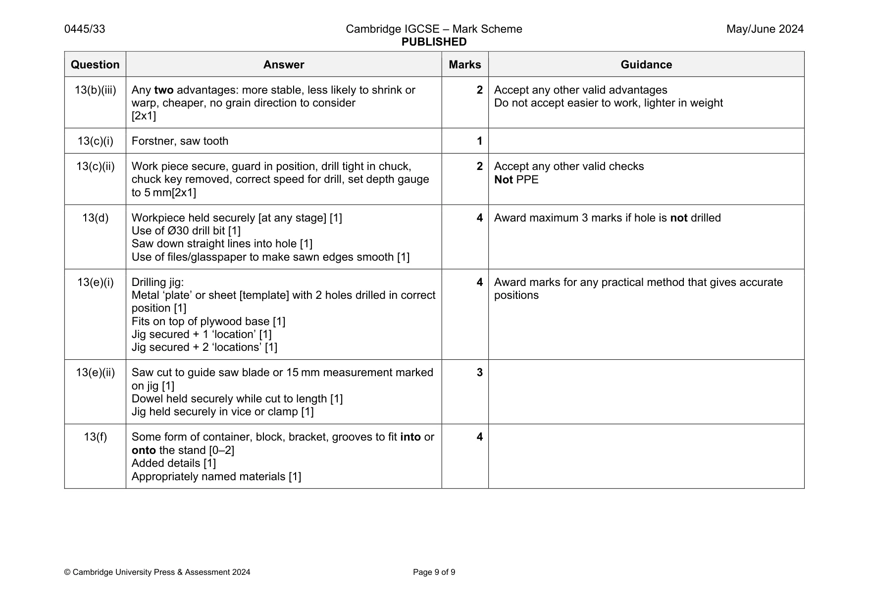
Mark scheme: 13(a) Any two specification points: gun must sit safely in stand, stand must be stable, made from durable material not affected by heat from gun, heat resistant, safe in use [2x1] Do not accept easy to clean or reference to aesthetics/appearance 13(b)(i) Wood-based material made by compressing and bonding thin sheets of wood, pulp or particles with an adhesive [1] 2 Accept reference to use of ‘waste’ materials 13(b)(ii) MDF 1 Do not accept chipboard, blockboard Question Answer Marks Guidance 13(b)(iii) Any two advantages: more stable, less likely to shrink or warp, cheaper, no grain direction to consider [2x1] 2 Accept any other valid advantages Do not accept easier to work, lighter in weight 13(c)(i) Forstner, saw tooth 1 13(c)(ii) Work piece secure, guard in position, drill tight in chuck, chuck key removed, correct speed for drill, set depth gauge to 5 mm[2x1] 2 Accept any other valid checks Not PPE 13(d) Workpiece held securely [at any stage] [1] Use of Ø30 drill bit [1] Saw down straight lines into hole [1] Use of files/glasspaper to make sawn edges smooth [1] 4 Award maximum 3 marks if hole is not drilled 13(e)(i) Drilling jig: Metal ‘plate’ or sheet [template] with 2 holes drilled in correct position [1] Fits on top of plywood base [1] Jig secured + 1 ‘location’ [1] Jig secured + 2 ‘locations’ [1] 4 Award marks for any practical method that gives accurate positions 13(e)(ii) Saw cut to guide saw blade or 15 mm measurement marked on jig [1] Dowel held securely while cut to length [1] Jig held securely in vice or clamp [1] 3 13(f) Some form of container, block, bracket, grooves to fit into or onto the stand [0–2] Added details [1] Appropriately named materials [1] 4
What was in this paper
The subtopics covered by these 13 questions, and how many questions each got. Open one in a new tab to see every Cambridge question on it.
What you needed in this session
Cambridge’s own grade thresholds for 2024 May/June, Paper 3 · Variant 3. A higher threshold means an easier paper — the bar moves with how the cohort did.