Cambridge IGCSE Design and Technology 0445 — 2025 Oct/Nov Paper 3 · Variant 2
0445/32/O/N/25 · 13 questions · 50 marks · 60 min
The question paper and its mark scheme, free to read here and free to download. This is Cambridge’s own paper, exactly as it was sat.
Question paper24 pages
Mark scheme13 pages
Answers below. Sit the paper first if you are practising.

Questions as text
Q1 · A solid wood board A, and the same board B, after it has warped
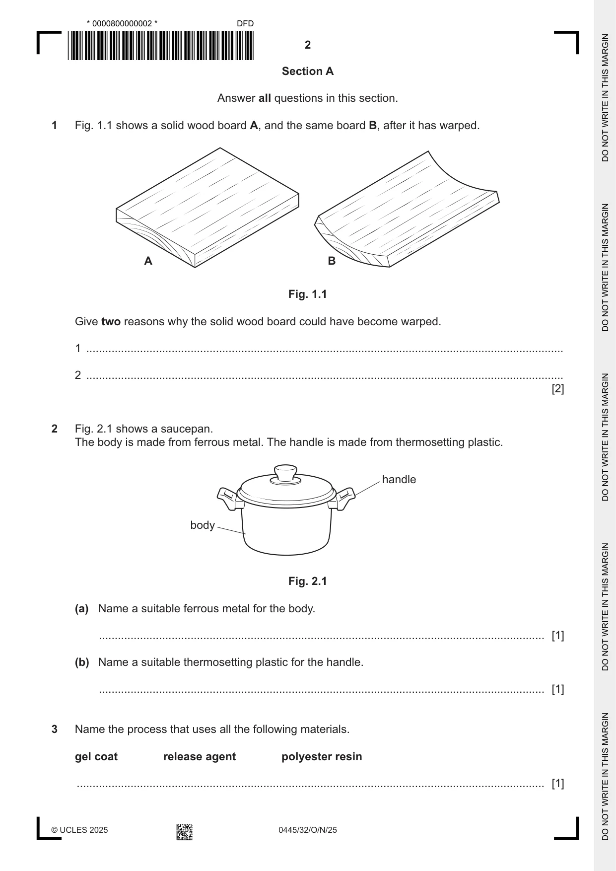
1 Fig. 1.1 shows a solid wood board A, and the same board B, after it has warped. A B Fig. 1.1 Give two reasons why the solid wood board could have become warped. 1 ....................................................................................................................................................... 2 ....................................................................................................................................................... [2]
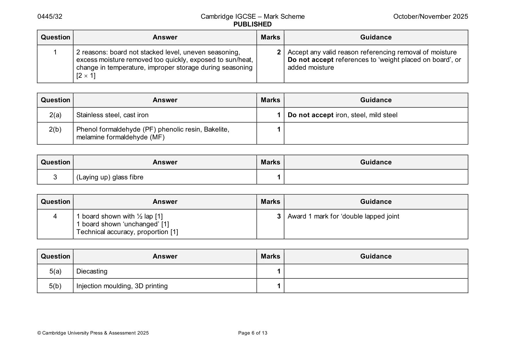
Mark scheme: Question Answer Marks Guidance 1 2 reasons: board not stacked level, uneven seasoning, 2 Accept any valid reason referencing removal of moisture excess moisture removed too quickly, exposed to sun/heat, Do not accept references to ‘weight placed on board’, or change in temperature, improper storage during seasoning added moisture [2 1]
Question 2
2 Fig. 2.1 shows a saucepan. The body is made from ferrous metal. The handle is made from thermosetting plastic. handle body Fig. 2.1 (a) Name a suitable ferrous metal for the body. ............................................................................................................................................. [1] (b) Name a suitable thermosetting plastic for the handle. ............................................................................................................................................. [1]
Mark scheme: 2(a) Stainless steel, cast iron 1 Do not accept iron, steel, mild steel 2(b) Phenol formaldehyde (PF) phenolic resin, Bakelite, 1 melamine formaldehyde (MF)
Q3 · Name the process that uses all the following materials
3 Name the process that uses all the following materials. gel coat release agent polyester resin .................................................................................................................................................... [1]
Mark scheme: 3 (Laying up) glass fibre 1
Q4 · Two wooden boards that will be joined together by means of a half-lap joint
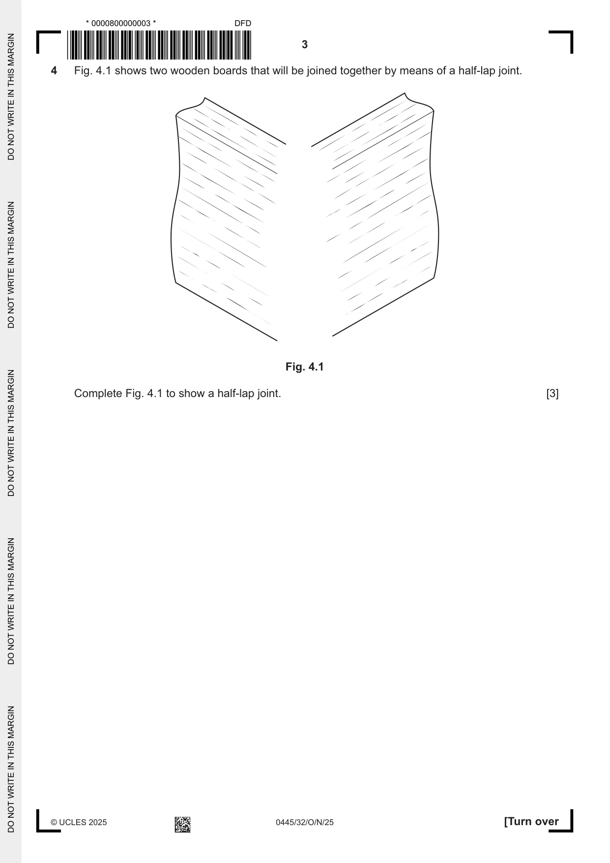
4 Fig. 4.1 shows two wooden boards that will be joined together by means of a half-lap joint. Fig. 4.1 Complete Fig. 4.1 to show a half-lap joint. [3]
Mark scheme: 4 1 board shown with ½ lap [1] 3 Award 1 mark for ‘double lapped joint 1 board shown ‘unchanged’ [1] Technical accuracy, proportion [1]
Q5 · A toy fire engine
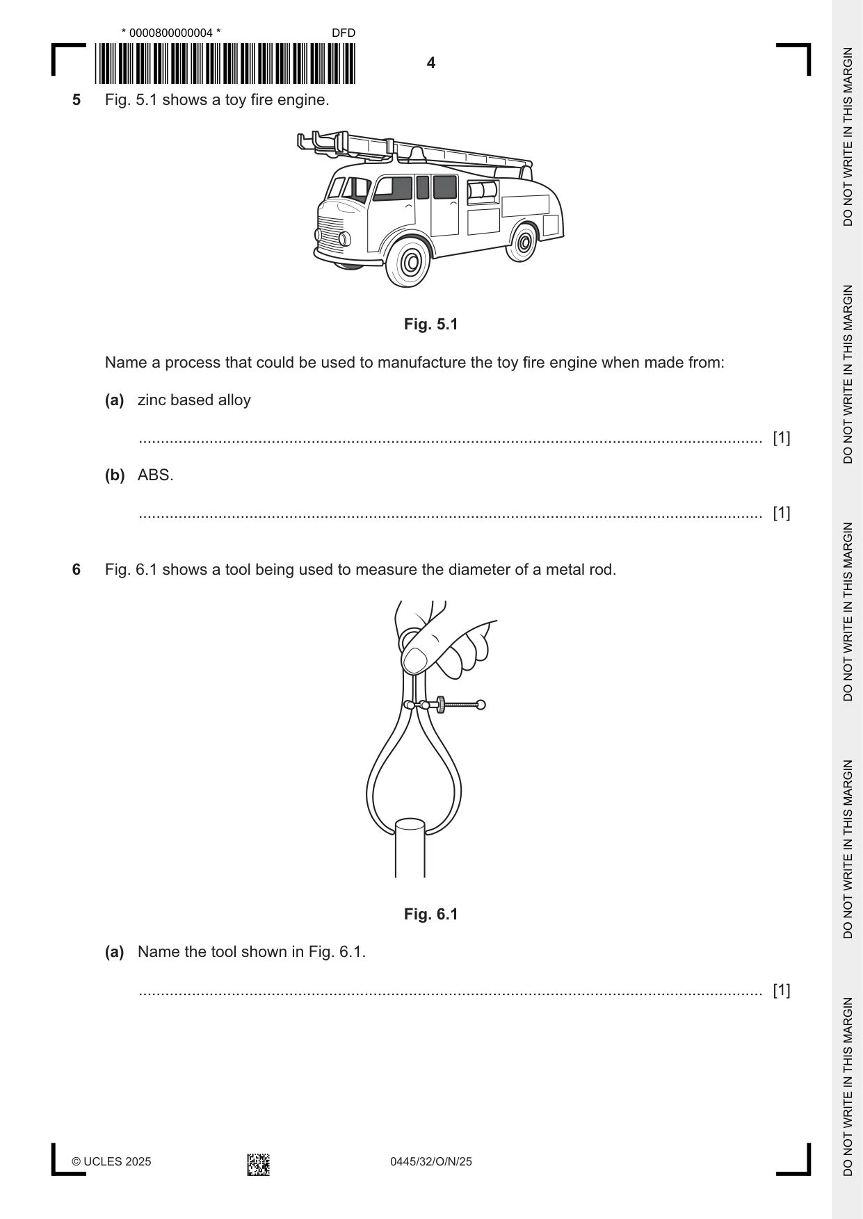
5 Fig. 5.1 shows a toy fire engine. Fig. 5.1 Name a process that could be used to manufacture the toy fire engine when made from: (a) zinc based alloy ............................................................................................................................................. [1] (b) ABS. ............................................................................................................................................. [1]
Mark scheme: 5(a) Diecasting 1 5(b) Injection moulding, 3D printing 1
Q6 · A tool being used to measure the diameter of a metal rod
6 Fig. 6.1 shows a tool being used to measure the diameter of a metal rod. Fig. 6.1 (a) Name the tool shown in Fig. 6.1. ............................................................................................................................................. [1] (b) Use sketches and notes to show how the actual measurement made by the tool would be read. [2]
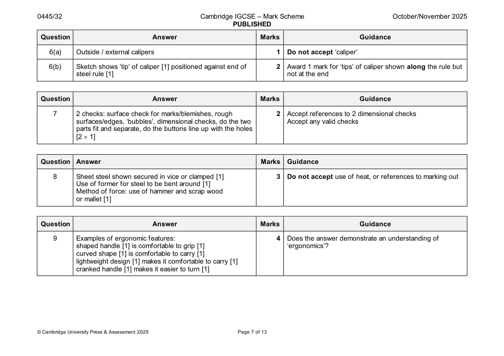
Mark scheme: 6(a) Outside / external calipers 1 Do not accept ‘caliper’ 6(b) Sketch shows ‘tip’ of caliper [1] positioned against end of 2 Award 1 mark for ‘tips’ of caliper shown along the rule but steel rule [1] not at the end
Q7 · The casing of a television remote control made from moulded plastic
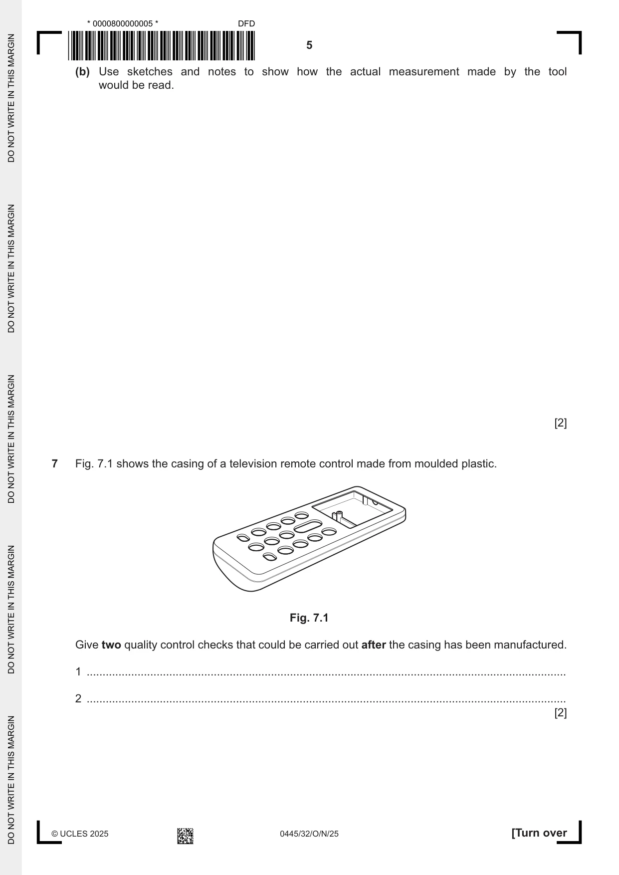
7 Fig. 7.1 shows the casing of a television remote control made from moulded plastic. Fig. 7.1 Give two quality control checks that could be carried out after the casing has been manufactured. 1 ....................................................................................................................................................... 2 ....................................................................................................................................................... [2]
Mark scheme: 7 2 checks: surface check for marks/blemishes, rough 2 Accept references to 2 dimensional checks surfaces/edges, ‘bubbles’, dimensional checks, do the two Accept any valid checks parts fit and separate, do the buttons line up with the holes [2 1] Question Answer Marks Guidance
Q8 · Views of a bracket made from 1.6 mm thick mild steel sheet
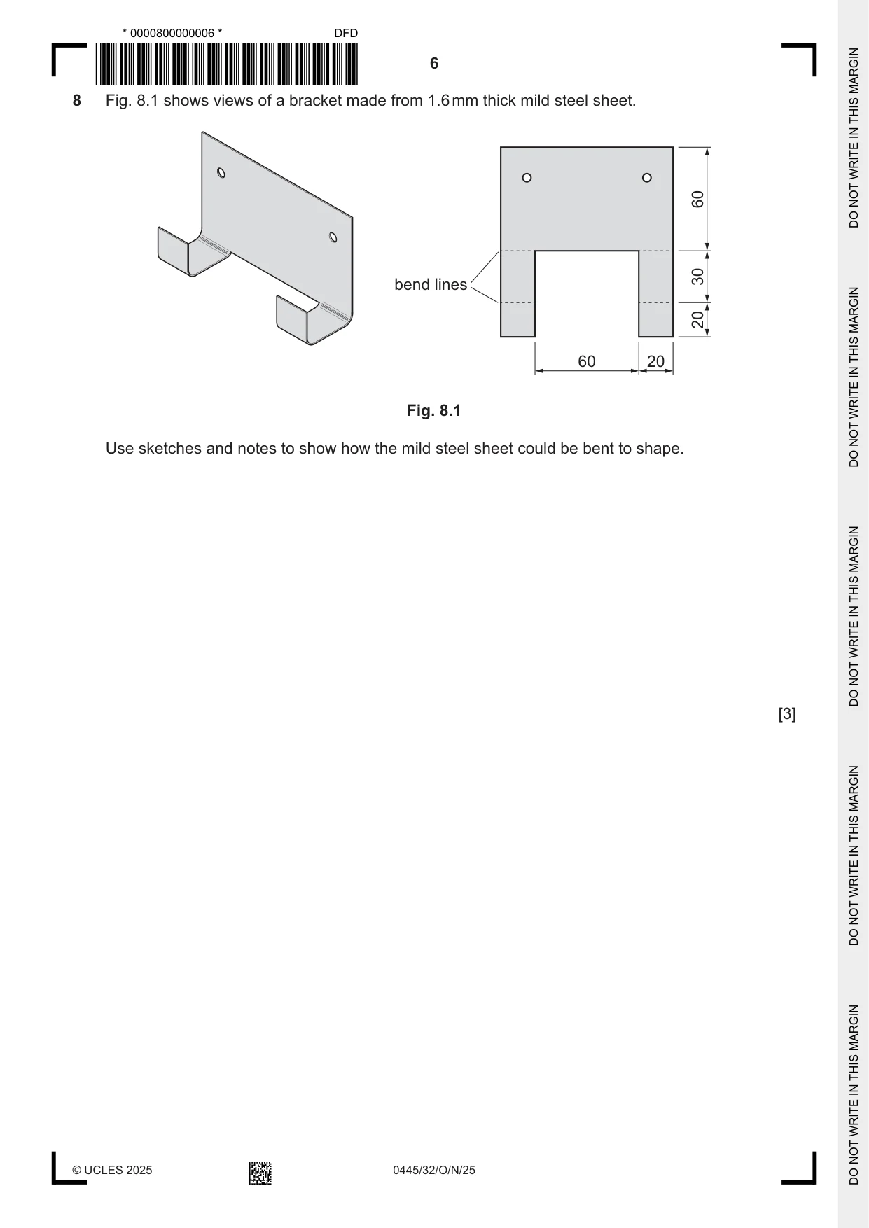
8 Fig. 8.1 shows views of a bracket made from 1.6 mm thick mild steel sheet. 60 30 bend lines 20 60 20 Fig. 8.1 Use sketches and notes to show how the mild steel sheet could be bent to shape. [3]
Mark scheme: 8 Sheet steel shown secured in vice or clamped [1] 3 Do not accept use of heat, or references to marking out Use of former for steel to be bent around [1] Method of force: use of hammer and scrap wood or mallet [1]
Q9 · A rechargeable wind-up radio
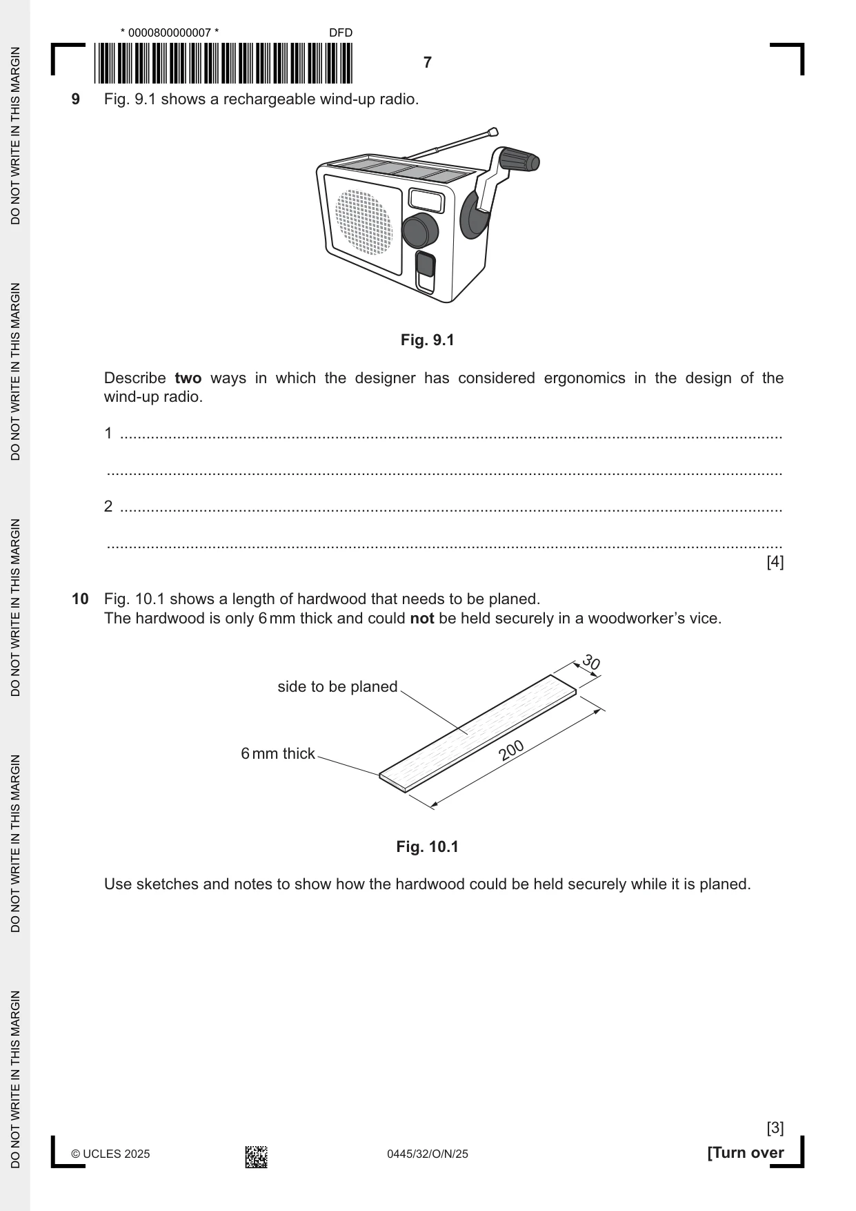
9 Fig. 9.1 shows a rechargeable wind-up radio. Fig. 9.1 Describe two ways in which the designer has considered ergonomics in the design of the wind-up radio. 1 ....................................................................................................................................................... .......................................................................................................................................................... 2 ....................................................................................................................................................... .......................................................................................................................................................... [4]
Mark scheme: 9 Examples of ergonomic features: 4 Does the answer demonstrate an understanding of shaped handle [1] is comfortable to grip [1] ‘ergonomics’? curved shape [1] is comfortable to carry [1] lightweight design [1] makes it comfortable to carry [1] cranked handle [1] makes it easier to turn [1]
Q10 · A length of hardwood that needs to be planed
10 Fig. 10.1 shows a length of hardwood that needs to be planed. The hardwood is only 6 mm thick and could not be held securely in a woodworker’s vice. 30 side to be planed 6 mm thick 200 Fig. 10.1 Use sketches and notes to show how the hardwood could be held securely while it is planed. [3]
Mark scheme: 10 Use of bench stop or clamped wood equivalent shown 3 Accept double-sided tape: clearly [0 – 2] Award 1 mark if stated only Award 2 marks if tape is shown on base of wood OR Use of pins/nails to secure wood to bench [0 – 2] Added explanatory notes [1]
Q11 · An incomplete design for scales and weights that could be used by children
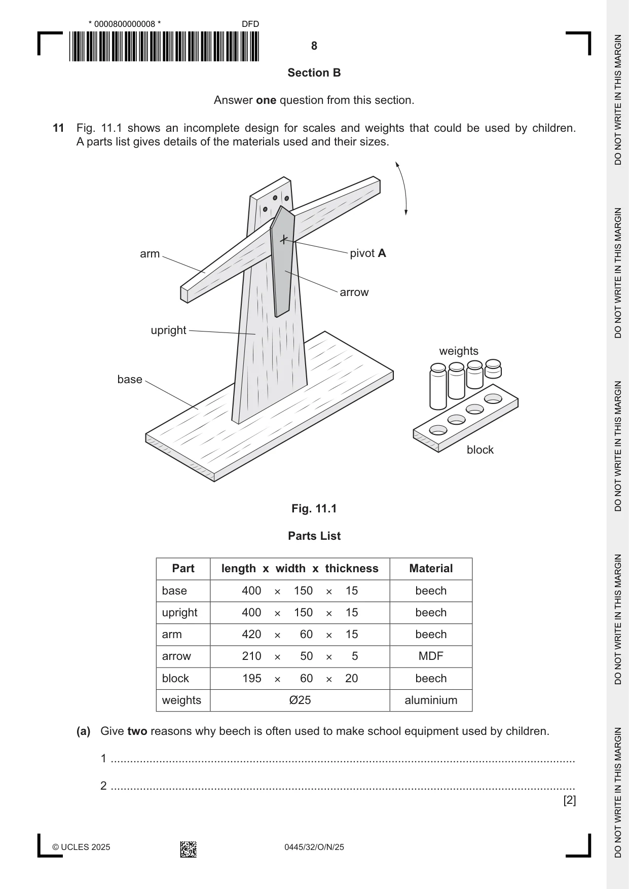
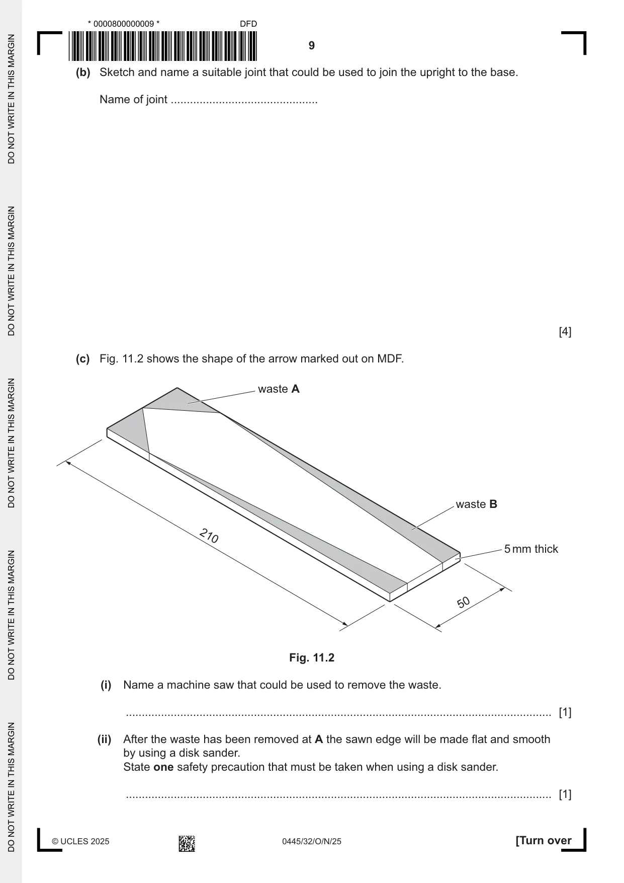
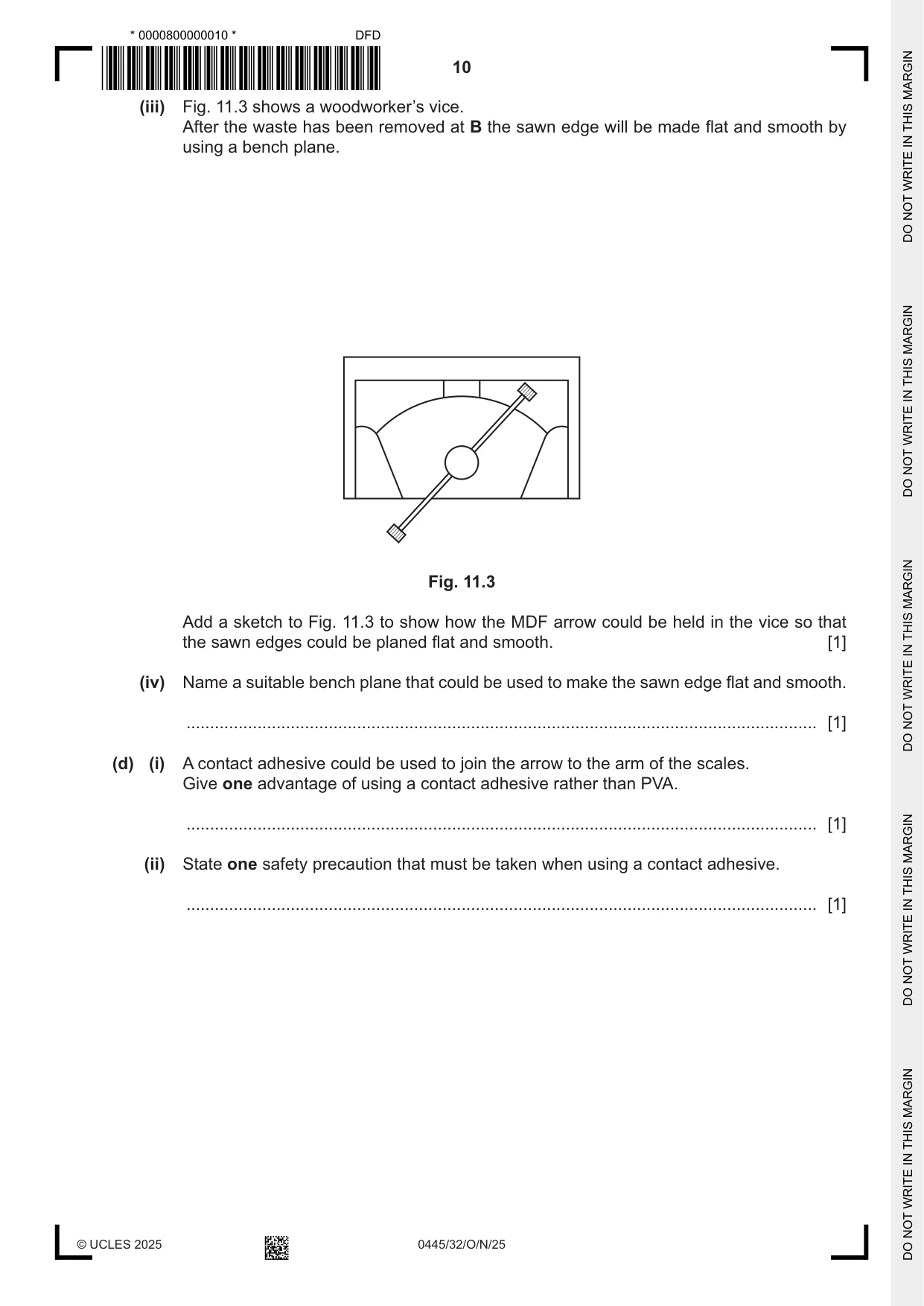
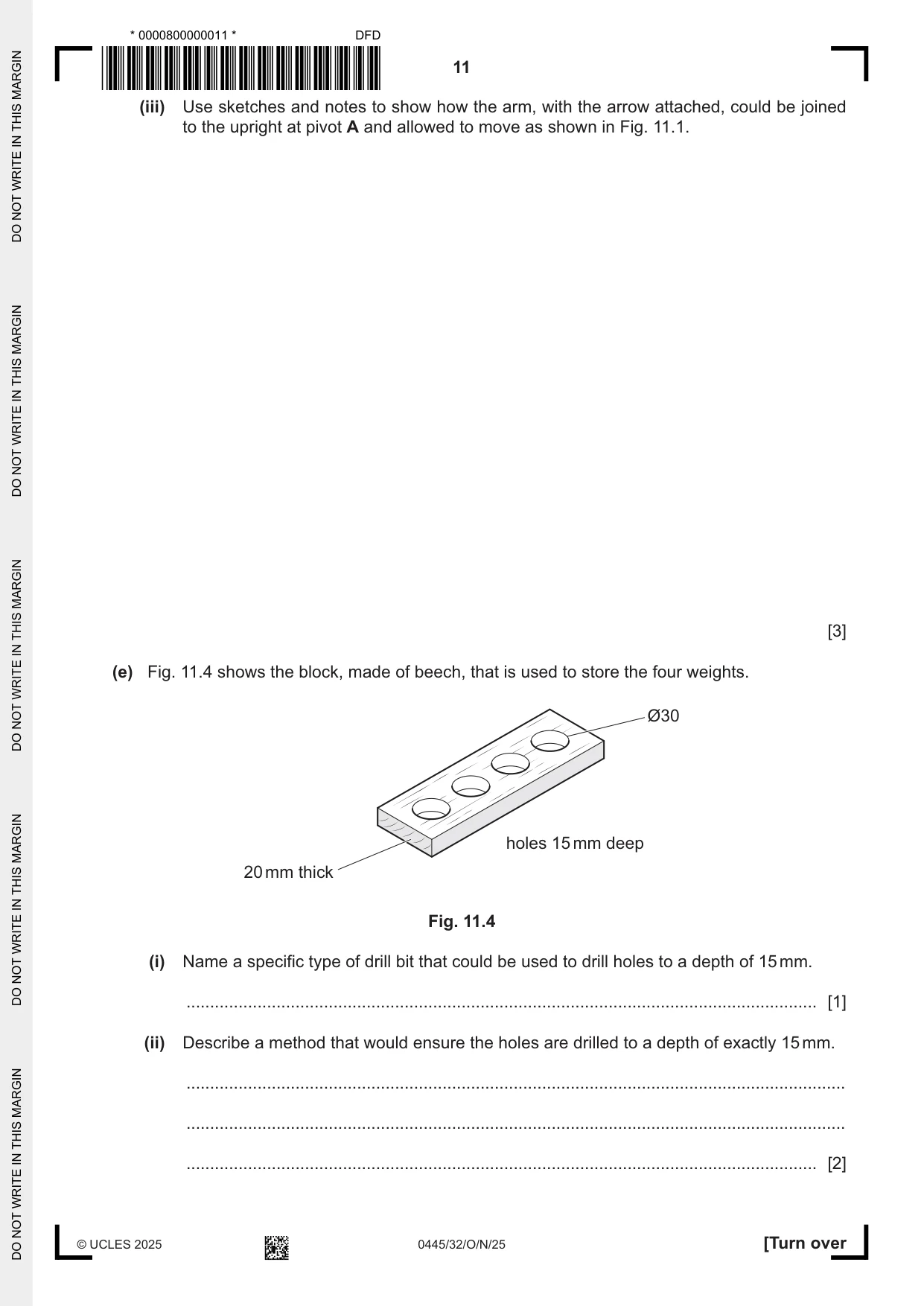
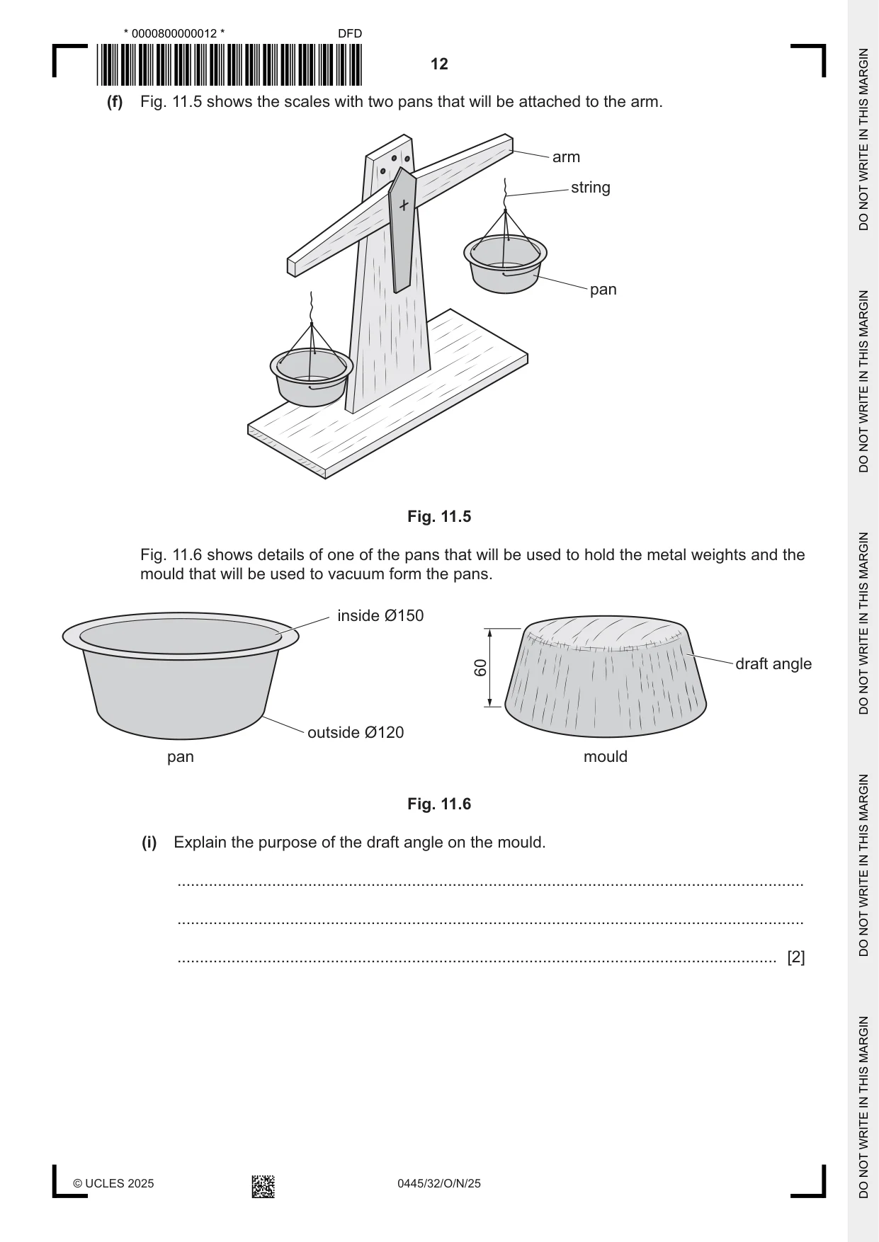
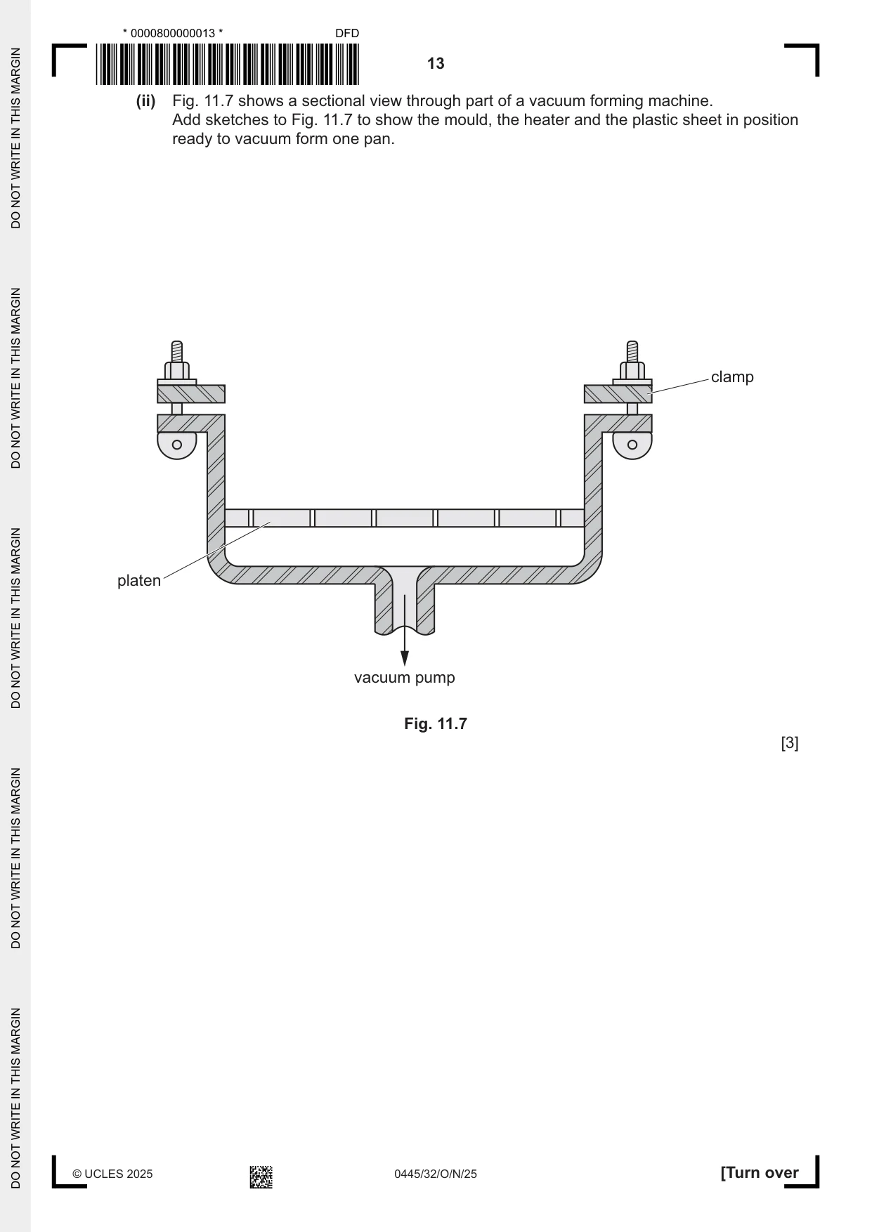
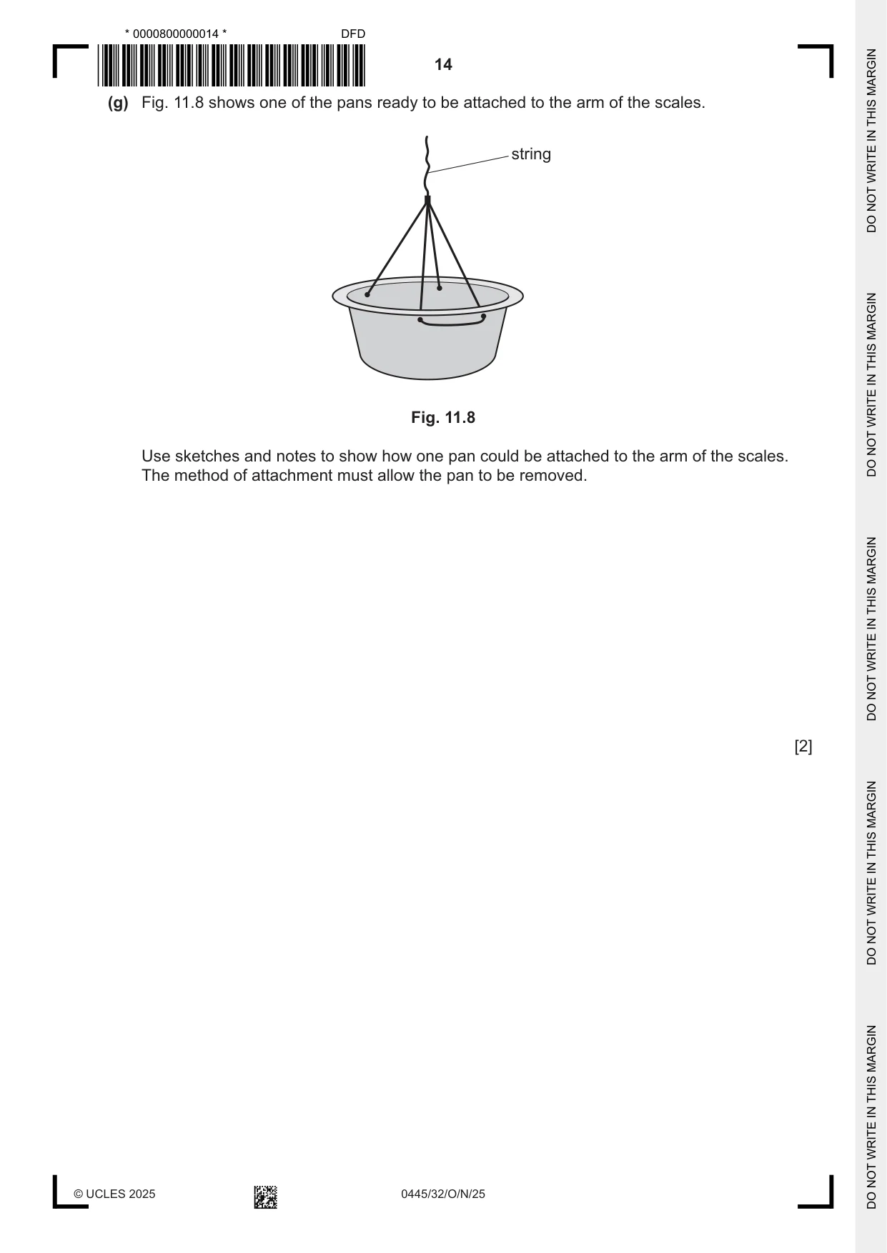
11 Fig. 11.1 shows an incomplete design for scales and weights that could be used by children. A parts list gives details of the materials used and their sizes. arm pivot A arrow upright weights base block Fig. 11.1 Parts List Part length x width x thickness Material base 400 × 150 × 15 beech upright 400 × 150 × 15 beech arm 420 × 60 × 15 beech arrow 210 × 50 × 5 MDF block 195 × 60 × 20 beech weights Ø25 aluminium (a) Give two reasons why beech is often used to make school equipment used by children. 1 ................................................................................................................................................ 2 ................................................................................................................................................ [2] (b) Sketch and name a suitable joint that could be used to join the upright to the base. Name of joint .............................................. [4] (c) Fig. 11.2 shows the shape of the arrow marked out on MDF. waste A waste B 210 5 mm thick 50 Fig. 11.2 (i) Name a machine saw that could be used to remove the waste. ..................................................................................................................................... [1] (ii) After the waste has been removed at A the sawn edge will be made flat and smooth by using a disk sander. State one safety precaution that must be taken when using a disk sander. ..................................................................................................................................... [1] (iii) Fig. 11.3 shows a woodworker’s vice. After the waste has been removed at B the sawn edge will be made flat and smooth by using a bench plane. Fig. 11.3 Add a sketch to Fig. 11.3 to show how the MDF arrow could be held in the vice so that the sawn edges could be planed flat and smooth. [1] (iv) Name a suitable bench plane that could be used to make the sawn edge flat and smooth. ..................................................................................................................................... [1] (d) (i) A contact adhesive could be used to join the arrow to the arm of the scales. Give one advantage of using a contact adhesive rather than PVA. ..................................................................................................................................... [1] (ii) State one safety precaution that must be taken when using a contact adhesive. ..................................................................................................................................... [1] (iii) Use sketches and notes to show how the arm, with the arrow attached, could be joined to the upright at pivot A and allowed to move as shown in Fig. 11.1. [3] (e) Fig. 11.4 shows the block, made of beech, that is used to store the four weights. Ø30 holes 15 mm deep 20 mm thick Fig. 11.4 (i) Name a specific type of drill bit that could be used to drill holes to a depth of 15 mm. ..................................................................................................................................... [1] (ii) Describe a method that would ensure the holes are drilled to a depth of exactly 15 mm. ........................................................................................................................................... ........................................................................................................................................... ..................................................................................................................................... [2] (f) Fig. 11.5 shows the scales with two pans that will be attached to the arm. arm string pan Fig. 11.5 Fig. 11.6 shows details of one of the pans that will be used to hold the metal weights and the mould that will be used to vacuum form the pans. inside Ø150 60 draft angle outside Ø120 pan mould Fig. 11.6 (i) Explain the purpose of the draft angle on the mould. ........................................................................................................................................... ........................................................................................................................................... ..................................................................................................................................... [2] (ii) Fig. 11.7 shows a sectional view through part of a vacuum forming machine. Add sketches to Fig. 11.7 to show the mould, the heater and the plastic sheet in position ready to vacuum form one pan. clamp platen vacuum pump Fig. 11.7 [3] (g) Fig. 11.8 shows one of the pans ready to be attached to the arm of the scales. string Fig. 11.8 Use sketches and notes to show how one pan could be attached to the arm of the scales. The method of attachment must allow the pan to be removed. [2]
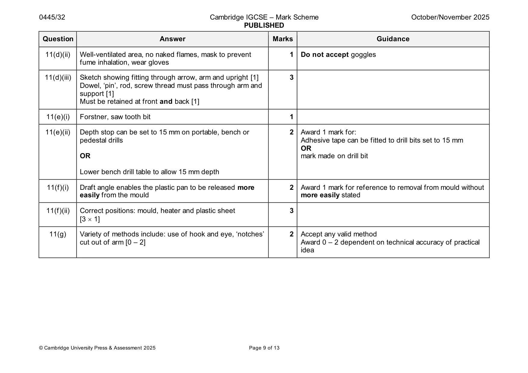
Mark scheme: 11(a) 2 reasons include: hard, tough, durable, resists splits and 2 Do not accept easy to work, lightweight, strong, cheap splintering, close-grained, finishes well, attractive [2 1] 11(b) Name of suitable joint: mortise and tenon, dowel, biscuit [1] 4 Accept ‘mortise’ Tenon shown with ‘shoulders’ [2] Complete width of ‘support’ shown in mortise 1 Quality of communication [1] Do not accept nails or screws through base into ‘support’ Dowels: min. 2 – max. 4 Biscuits: min. 2 – max. 3 11(c)(i) Circular saw, table saw, band saw, scroll saw, Hegner saw, 1 jig saw 11(c)(ii) Fingers behind surfaces being sanded, face mask, safety 1 Do not accept gloves, apron glasses, goggles, glasses, respirator, hair tied back, no loose clothing, no spectators, hold the workpiece securely 11(c)(iii) Hardwood shown angled so that sawn edge B could be 1 horizontal when planed 11(c)(iv) Smoothing plane, jack plane, block plane 1 11(d)(i) Contact adhesive bonds immediately, no need for clamping, 1 Do not accept stronger PVA takes 2–3 hours to set 11(d)(ii) Well-ventilated area, no naked flames, mask to prevent 1 Do not accept goggles fume inhalation, wear gloves 11(d)(iii) Sketch showing fitting through arrow, arm and upright [1] 3 Dowel, ‘pin’, rod, screw thread must pass through arm and support [1] Must be retained at front and back [1] 11(e)(i) Forstner, saw tooth bit 1 11(e)(ii) Depth stop can be set to 15 mm on portable, bench or 2 Award 1 mark for: pedestal drills Adhesive tape can be fitted to drill bits set to 15 mm OR OR mark made on drill bit Lower bench drill table to allow 15 mm depth 11(f)(i) Draft angle enables the plastic pan to be released more 2 Award 1 mark for reference to removal from mould without easily from the mould more easily stated 11(f)(ii) Correct positions: mould, heater and plastic sheet 3 [3 1] 11(g) Variety of methods include: use of hook and eye, ‘notches’ 2 Accept any valid method cut out of arm [0 – 2] Award 0 – 2 dependent on technical accuracy of practical idea
Q12 · A holder to store a gaming controller and a headset
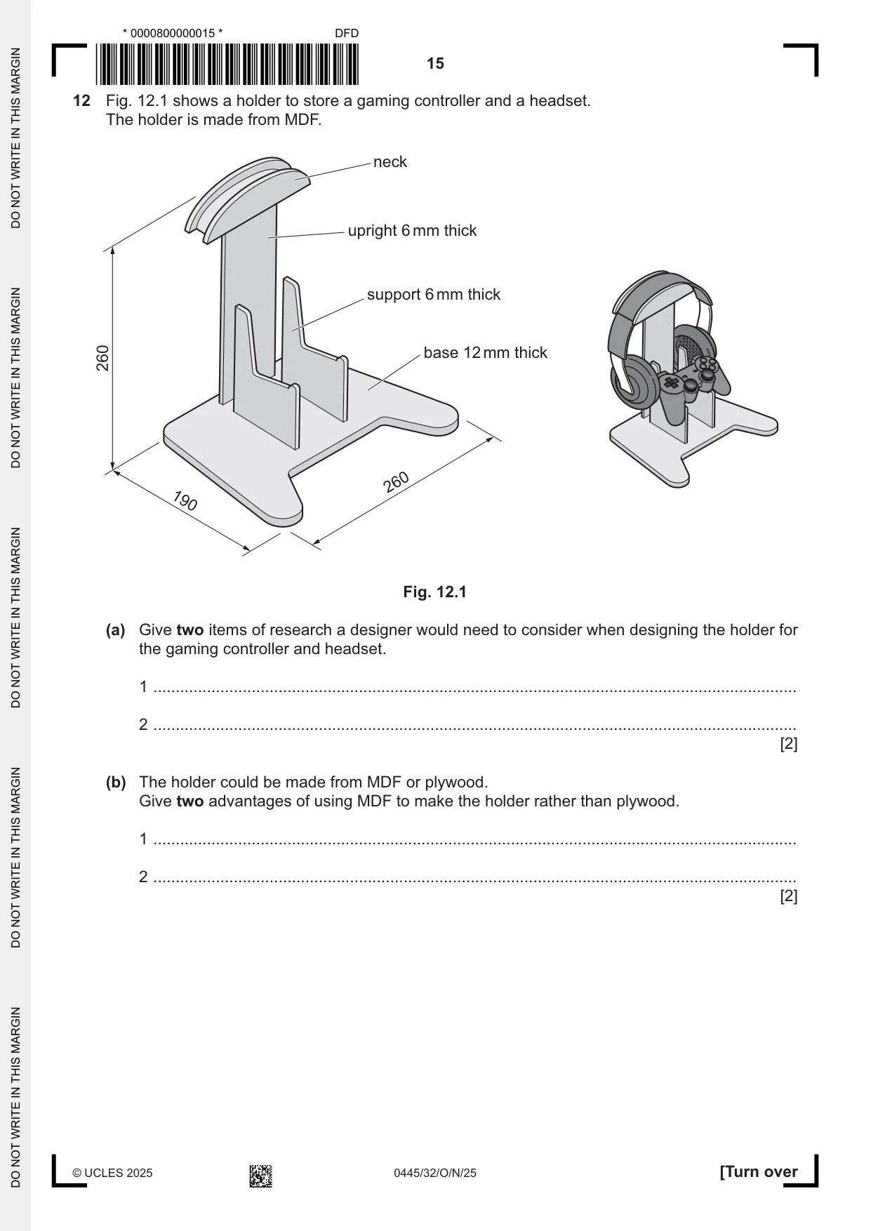
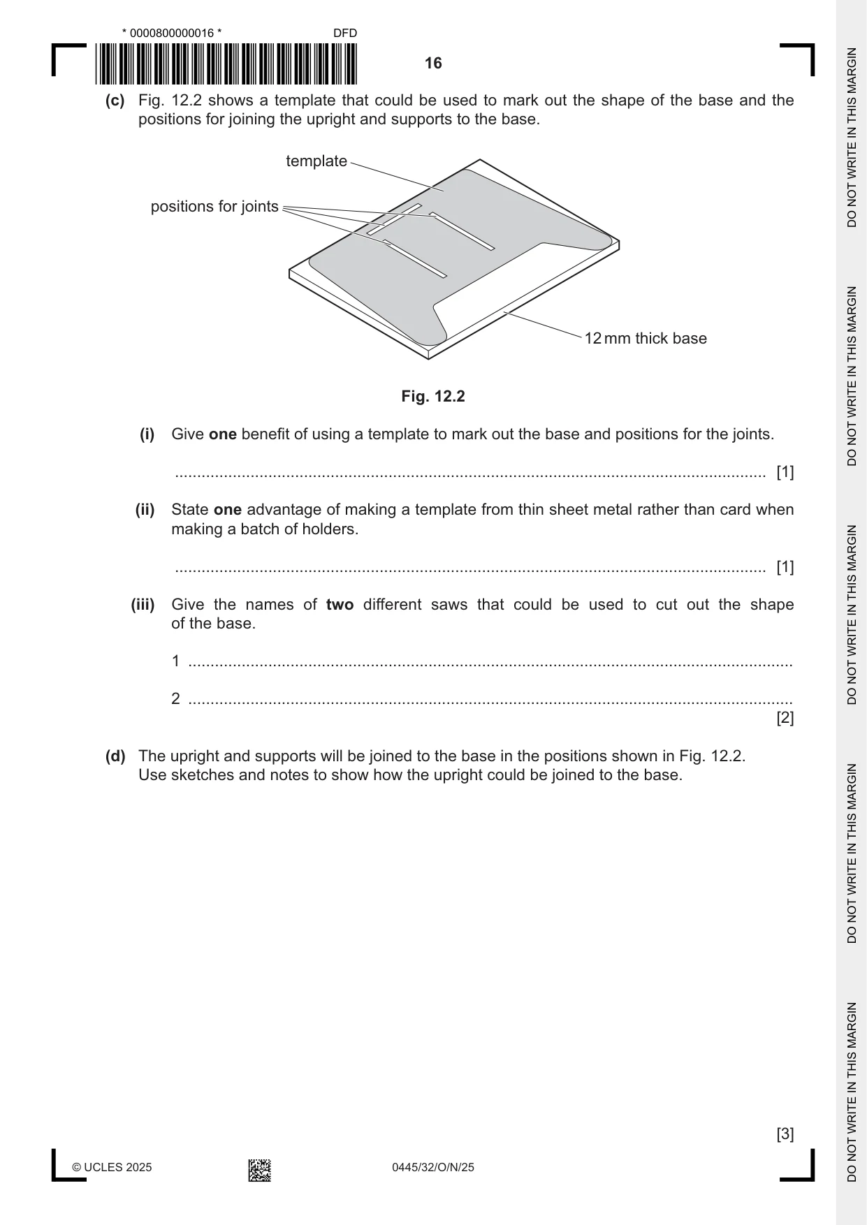
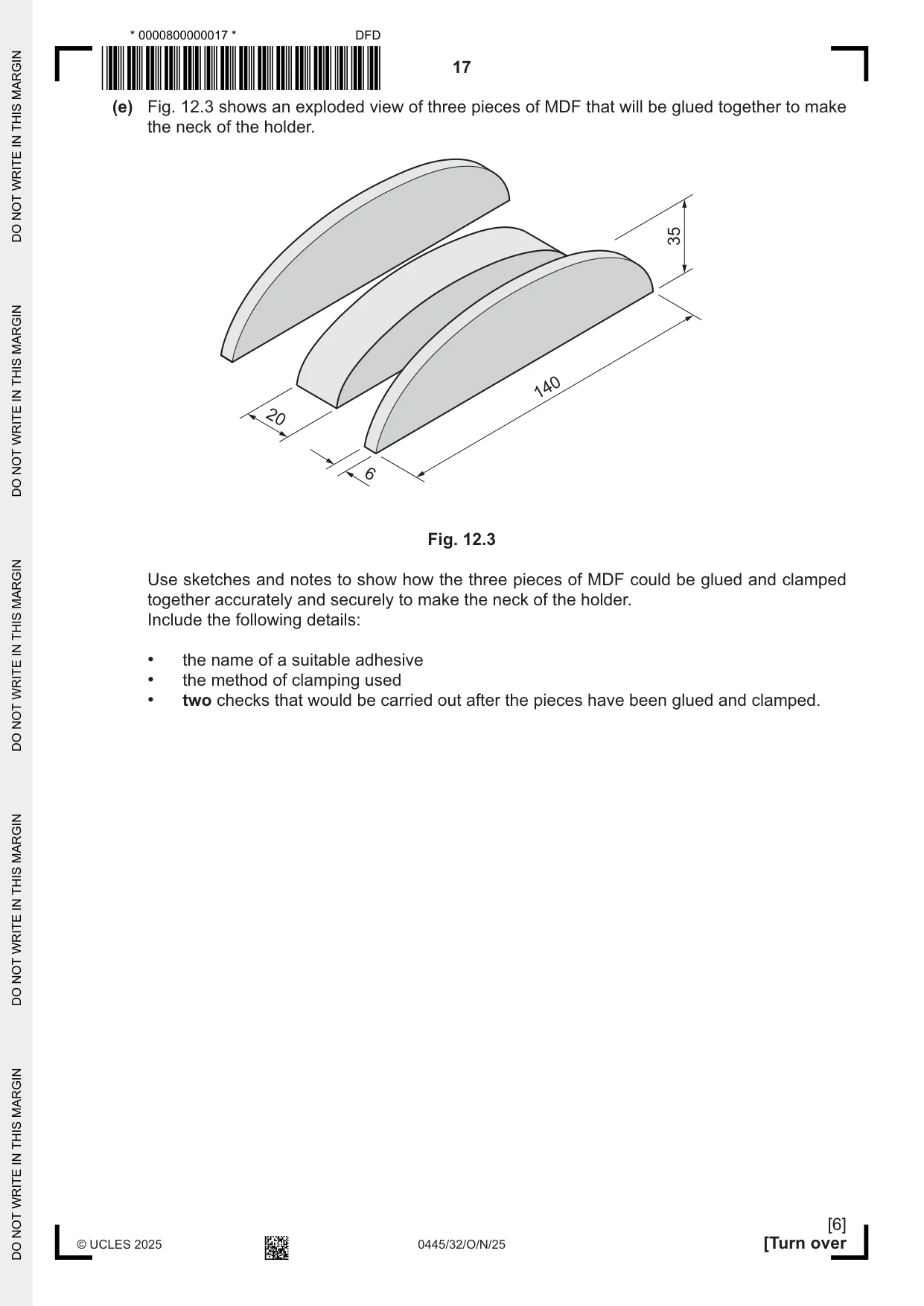
12 Fig. 12.1 shows a holder to store a gaming controller and a headset. The holder is made from MDF. neck upright 6 mm thick support 6 mm thick 260 base 12 mm thick 260 190 Fig. 12.1 (a) Give two items of research a designer would need to consider when designing the holder for the gaming controller and headset. 1 ................................................................................................................................................ 2 ................................................................................................................................................ [2] (b) The holder could be made from MDF or plywood. Give two advantages of using MDF to make the holder rather than plywood. 1 ................................................................................................................................................ 2 ................................................................................................................................................ [2] (c) Fig. 12.2 shows a template that could be used to mark out the shape of the base and the positions for joining the upright and supports to the base. template positions for joints 12 mm thick base Fig. 12.2 (i) Give one benefit of using a template to mark out the base and positions for the joints. ..................................................................................................................................... [1] (ii) State one advantage of making a template from thin sheet metal rather than card when making a batch of holders. ..................................................................................................................................... [1] (iii) Give the names of two different saws that could be used to cut out the shape of the base. 1 ........................................................................................................................................ 2 ........................................................................................................................................ [2] (d) The upright and supports will be joined to the base in the positions shown in Fig. 12.2. Use sketches and notes to show how the upright could be joined to the base. [3] (e) Fig. 12.3 shows an exploded view of three pieces of MDF that will be glued together to make the neck of the holder. 35 140 20 6 Fig. 12.3 Use sketches and notes to show how the three pieces of MDF could be glued and clamped together accurately and securely to make the neck of the holder. Include the following details: • the name of a suitable adhesive • the method of clamping used • two checks that would be carried out after the pieces have been glued and clamped. [6] (f) The parts of the holder will be painted before they are assembled. (i) The surfaces of the MDF will be sanded using a fine grade glasspaper wrapped around a cork sanding block. Give one benefit of using a cork sanding block with the glasspaper. ..................................................................................................................................... [1] (ii) A primer coat of paint will be applied to the MDF. Describe the purpose of a primer coat. ........................................................................................................................................... ..................................................................................................................................... [2] (iii) The final coat of paint will be sprayed onto the surfaces. Give one advantage of spraying the paint rather than by using a brush. ..................................................................................................................................... [1] (iv) State one safety precaution that must be taken when spray painting. ..................................................................................................................................... [1] (g) Explain how an evaluation of the final product could be carried out. ................................................................................................................................................... ................................................................................................................................................... ................................................................................................................................................... ............................................................................................................................................. [3]
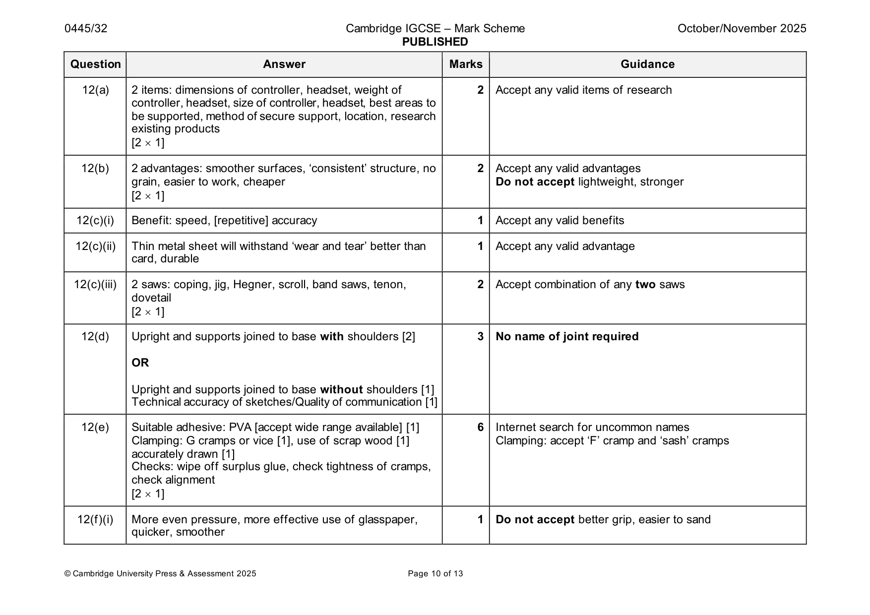
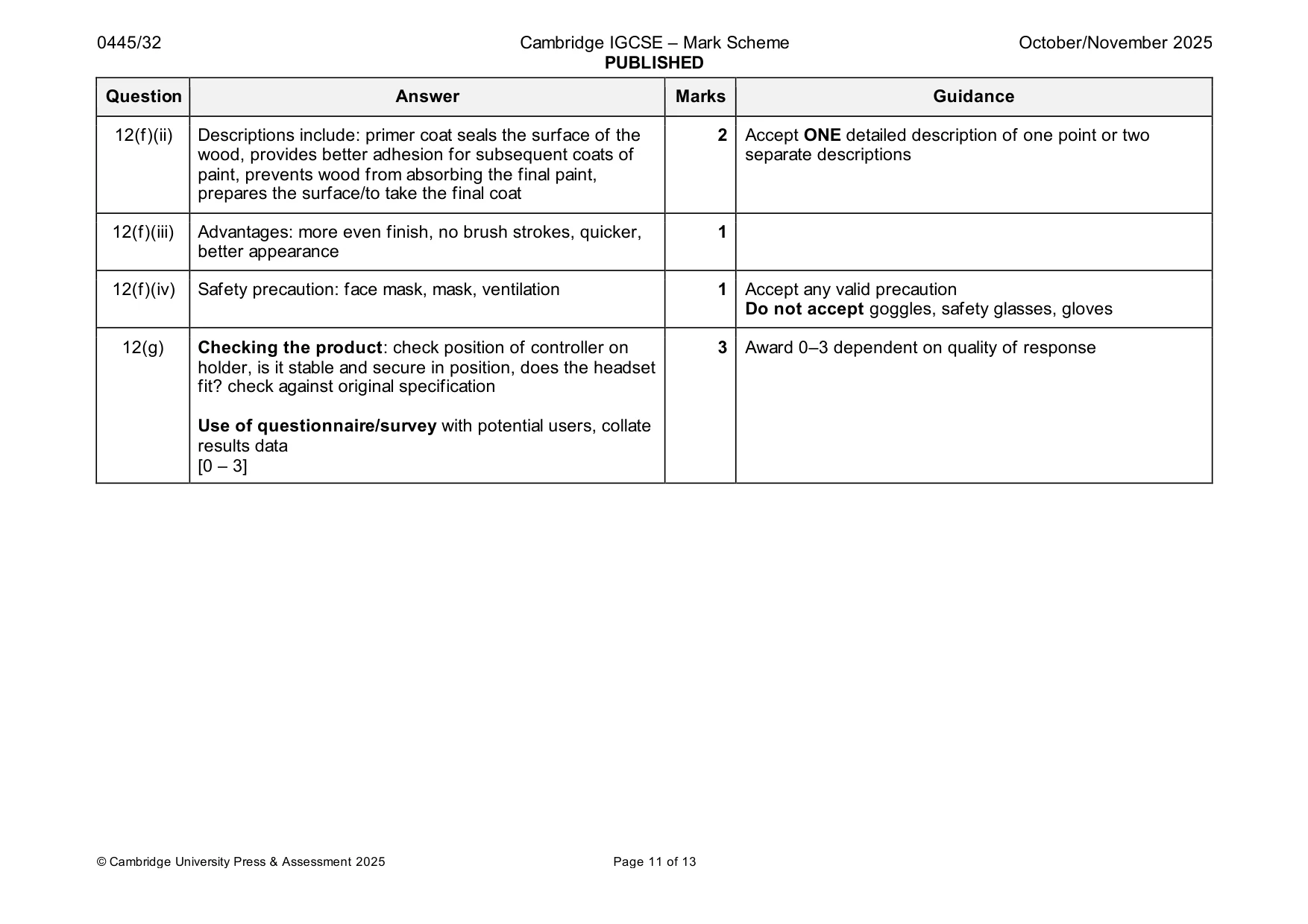
Mark scheme: 12(a) 2 items: dimensions of controller, headset, weight of 2 Accept any valid items of research controller, headset, size of controller, headset, best areas to be supported, method of secure support, location, research existing products [2 1] 12(b) 2 advantages: smoother surfaces, ‘consistent’ structure, no 2 Accept any valid advantages grain, easier to work, cheaper Do not accept lightweight, stronger [2 1] 12(c)(i) Benefit: speed, [repetitive] accuracy 1 Accept any valid benefits 12(c)(ii) Thin metal sheet will withstand ‘wear and tear’ better than 1 Accept any valid advantage card, durable 12(c)(iii) 2 saws: coping, jig, Hegner, scroll, band saws, tenon, 2 Accept combination of any two saws dovetail [2 1] 12(d) Upright and supports joined to base with shoulders [2] 3 No name of joint required OR Upright and supports joined to base without shoulders [1] Technical accuracy of sketches/Quality of communication [1] 12(e) Suitable adhesive: PVA [accept wide range available] [1] 6 Internet search for uncommon names Clamping: G cramps or vice [1], use of scrap wood [1] Clamping: accept ‘F’ cramp and ‘sash’ cramps accurately drawn [1] Checks: wipe off surplus glue, check tightness of cramps, check alignment [2 1] 12(f)(i) More even pressure, more effective use of glasspaper, 1 Do not accept better grip, easier to sand quicker, smoother 12(f)(ii) Descriptions include: primer coat seals the surface of the 2 Accept ONE detailed description of one point or two wood, provides better adhesion for subsequent coats of separate descriptions paint, prevents wood from absorbing the final paint, prepares the surface/to take the final coat 12(f)(iii) Advantages: more even finish, no brush strokes, quicker, 1 better appearance 12(f)(iv) Safety precaution: face mask, mask, ventilation 1 Accept any valid precaution Do not accept goggles, safety glasses, gloves 12(g) Checking the product: check position of controller on 3 Award 0–3 dependent on quality of response holder, is it stable and secure in position, does the headset fit? check against original specification Use of questionnaire/survey with potential users, collate results data [0 – 3]
Q13 · An incomplete design for a wall-mounted adjustable shelving unit
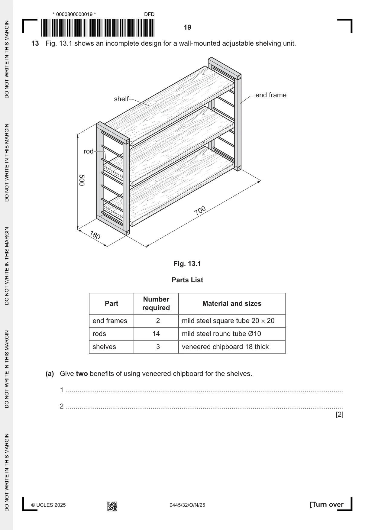
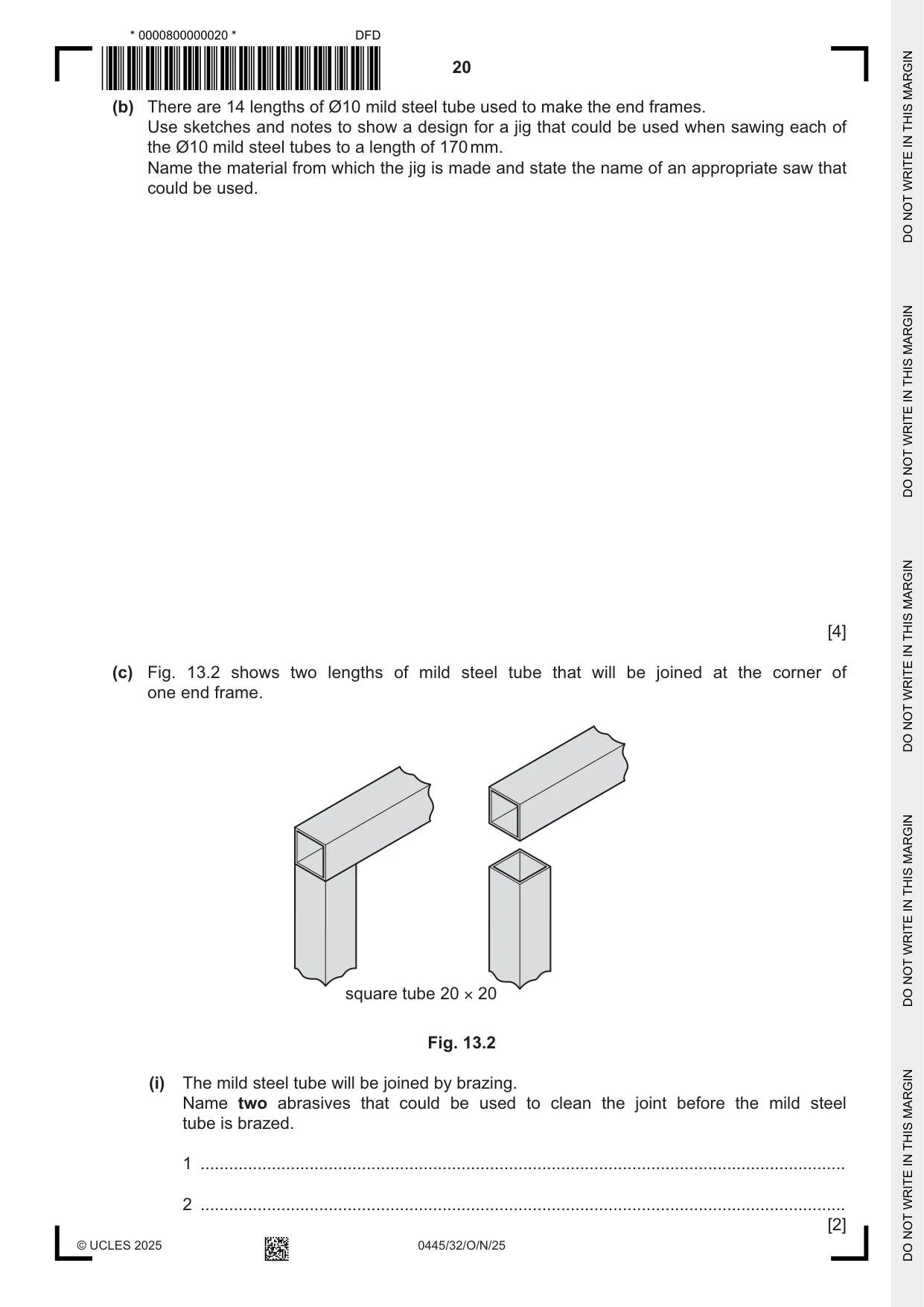
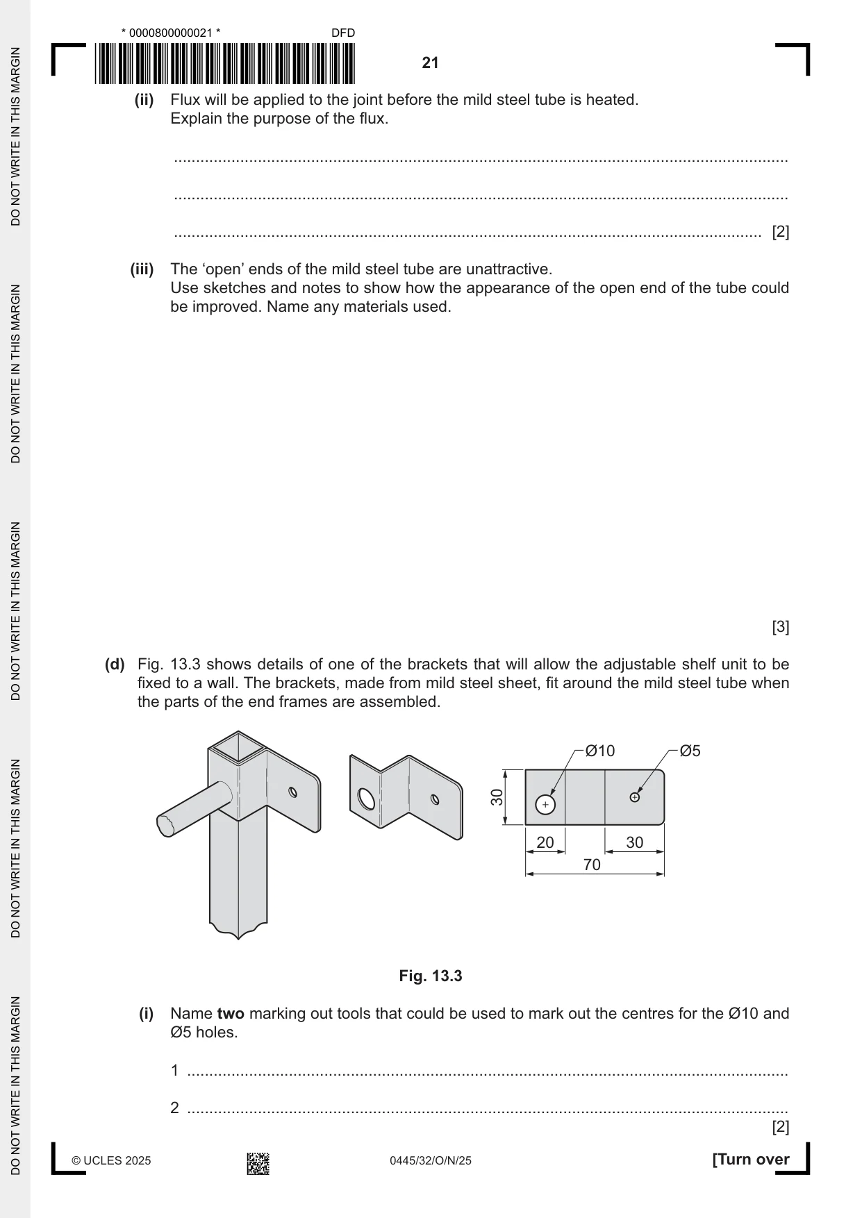
13 Fig. 13.1 shows an incomplete design for a wall-mounted adjustable shelving unit. end frame shelf rod 500 700 180 Fig. 13.1 Parts List Number Part Material and sizes required end frames 2 mild steel square tube 20 × 20 rods 14 mild steel round tube Ø10 shelves 3 veneered chipboard 18 thick (a) Give two benefits of using veneered chipboard for the shelves. 1 ................................................................................................................................................ 2 ................................................................................................................................................ [2] (b) There are 14 lengths of Ø10 mild steel tube used to make the end frames. Use sketches and notes to show a design for a jig that could be used when sawing each of the Ø10 mild steel tubes to a length of 170 mm. Name the material from which the jig is made and state the name of an appropriate saw that could be used. [4] (c) Fig. 13.2 shows two lengths of mild steel tube that will be joined at the corner of one end frame. square tube 20 × 20 Fig. 13.2 (i) The mild steel tube will be joined by brazing. Name two abrasives that could be used to clean the joint before the mild steel tube is brazed. 1 ........................................................................................................................................ 2 ........................................................................................................................................ [2] (ii) Flux will be applied to the joint before the mild steel tube is heated. Explain the purpose of the flux. ........................................................................................................................................... ........................................................................................................................................... ..................................................................................................................................... [2] (iii) The ‘open’ ends of the mild steel tube are unattractive. Use sketches and notes to show how the appearance of the open end of the tube could be improved. Name any materials used. [3] (d) Fig. 13.3 shows details of one of the brackets that will allow the adjustable shelf unit to be fixed to a wall. The brackets, made from mild steel sheet, fit around the mild steel tube when the parts of the end frames are assembled. Ø10 Ø5 30 20 30 70 Fig. 13.3 (i) Name two marking out tools that could be used to mark out the centres for the Ø10 and Ø5 holes. 1 ........................................................................................................................................ 2 ........................................................................................................................................ [2]
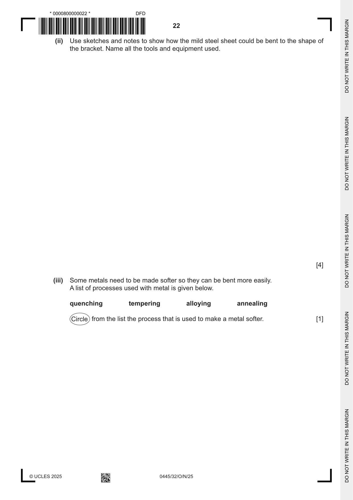
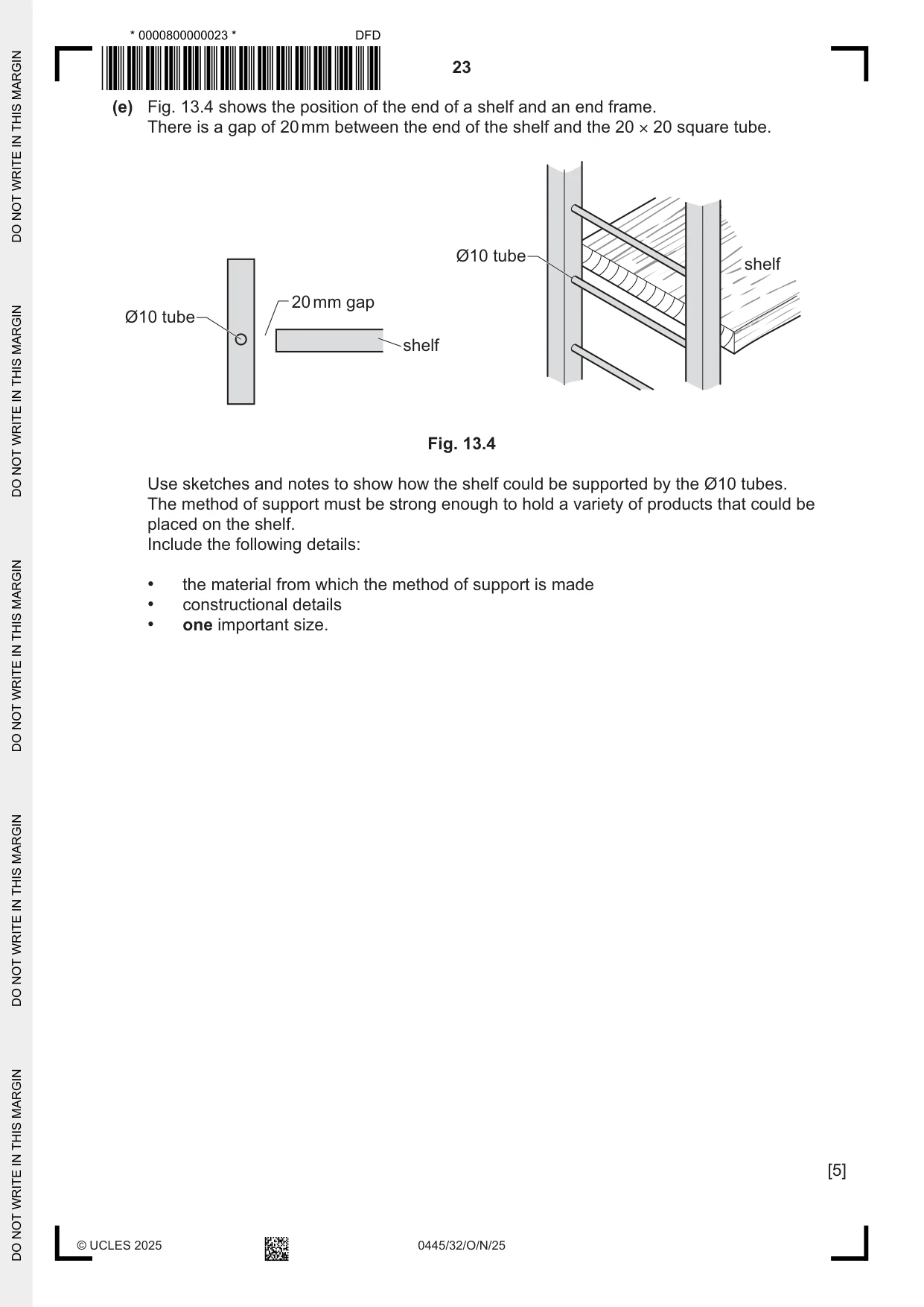
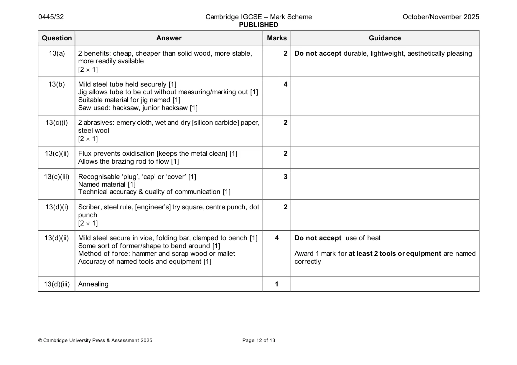
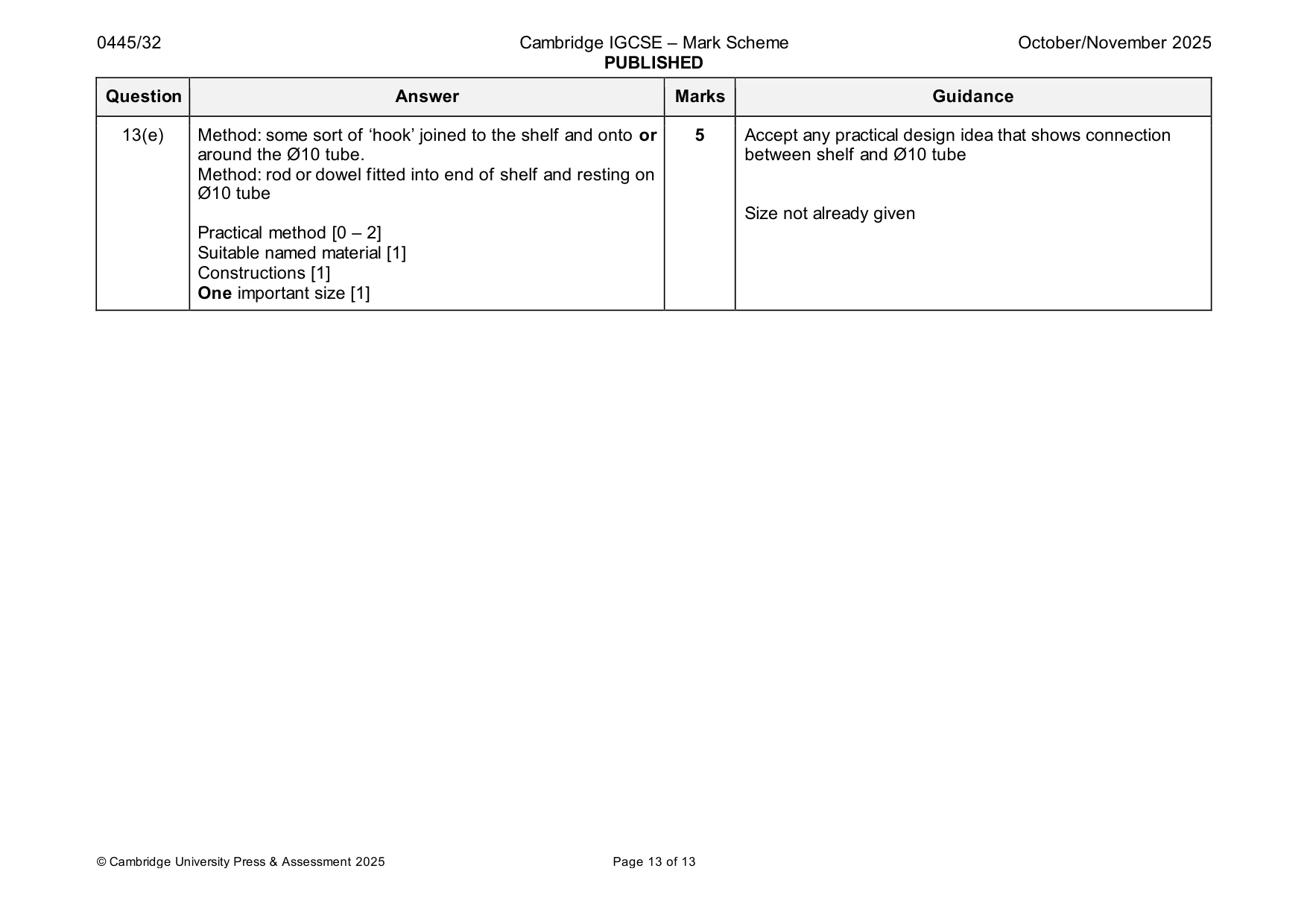
Mark scheme: 13(a) 2 benefits: cheap, cheaper than solid wood, more stable, 2 Do not accept durable, lightweight, aesthetically pleasing more readily available [2 1] 13(b) Mild steel tube held securely [1] 4 Jig allows tube to be cut without measuring/marking out [1] Suitable material for jig named [1] Saw used: hacksaw, junior hacksaw [1] 13(c)(i) 2 abrasives: emery cloth, wet and dry [silicon carbide] paper, 2 steel wool [2 1] 13(c)(ii) Flux prevents oxidisation [keeps the metal clean] [1] 2 Allows the brazing rod to flow [1] 13(c)(iii) Recognisable ‘plug’, ‘cap’ or ‘cover’ [1] 3 Named material [1] Technical accuracy & quality of communication [1] 13(d)(i) Scriber, steel rule, [engineer’s] try square, centre punch, dot 2 punch [2 1] 13(d)(ii) Mild steel secure in vice, folding bar, clamped to bench [1] 4 Do not accept use of heat Some sort of former/shape to bend around [1] Method of force: hammer and scrap wood or mallet Award 1 mark for at least 2 tools or equipment are named Accuracy of named tools and equipment [1] correctly 13(d)(iii) Annealing 1 13(e) Method: some sort of ‘hook’ joined to the shelf and onto or 5 Accept any practical design idea that shows connection around the Ø10 tube. between shelf and Ø10 tube Method: rod or dowel fitted into end of shelf and resting on Ø10 tube Size not already given Practical method [0 – 2] Suitable named material [1] Constructions [1] One important size [1]
What was in this paper
The subtopics covered by these 13 questions, and how many questions each got. Open one in a new tab to see every Cambridge question on it.
What you needed in this session
Cambridge’s own grade thresholds for 2025 Oct/Nov, Paper 3 · Variant 2. A higher threshold means an easier paper — the bar moves with how the cohort did.