Cambridge IGCSE Design and Technology 0445 — 2024 May/June Paper 3 · Variant 1
0445/31/M/J/24 · 13 questions · 50 marks · 60 min
The question paper and its mark scheme, free to read here and free to download. This is Cambridge’s own paper, exactly as it was sat.
Question paper20 pages
Mark scheme9 pages
Answers below. Sit the paper first if you are practising.
Questions as text
Q1 · A tennis racket made from carbon fibre reinforced plastic (CFRP)
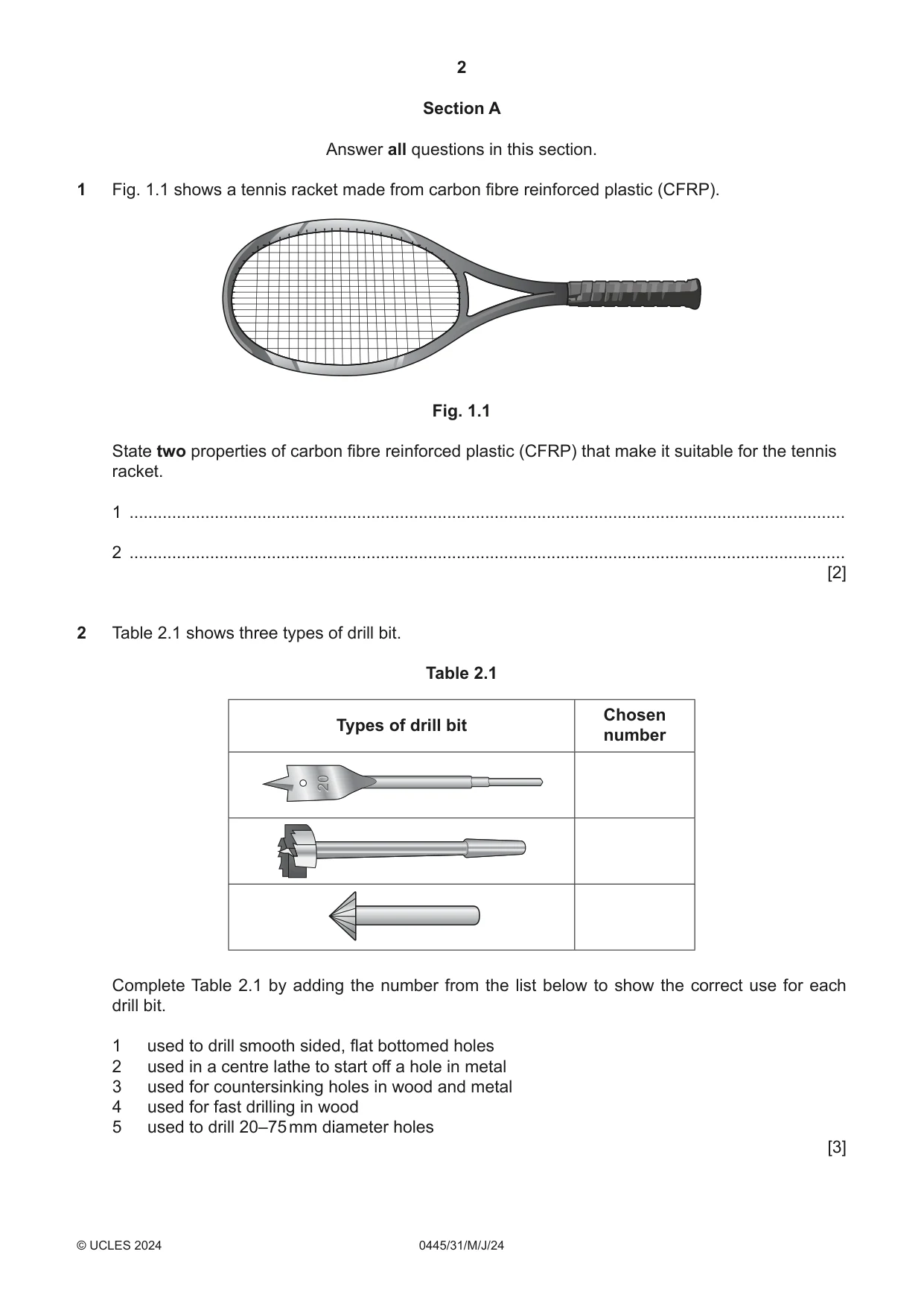
1 Fig. 1.1 shows a tennis racket made from carbon fibre reinforced plastic (CFRP). Fig. 1.1 State two properties of carbon fibre reinforced plastic (CFRP) that make it suitable for the tennis racket. 1 ....................................................................................................................................................... 2 ....................................................................................................................................................... [2]
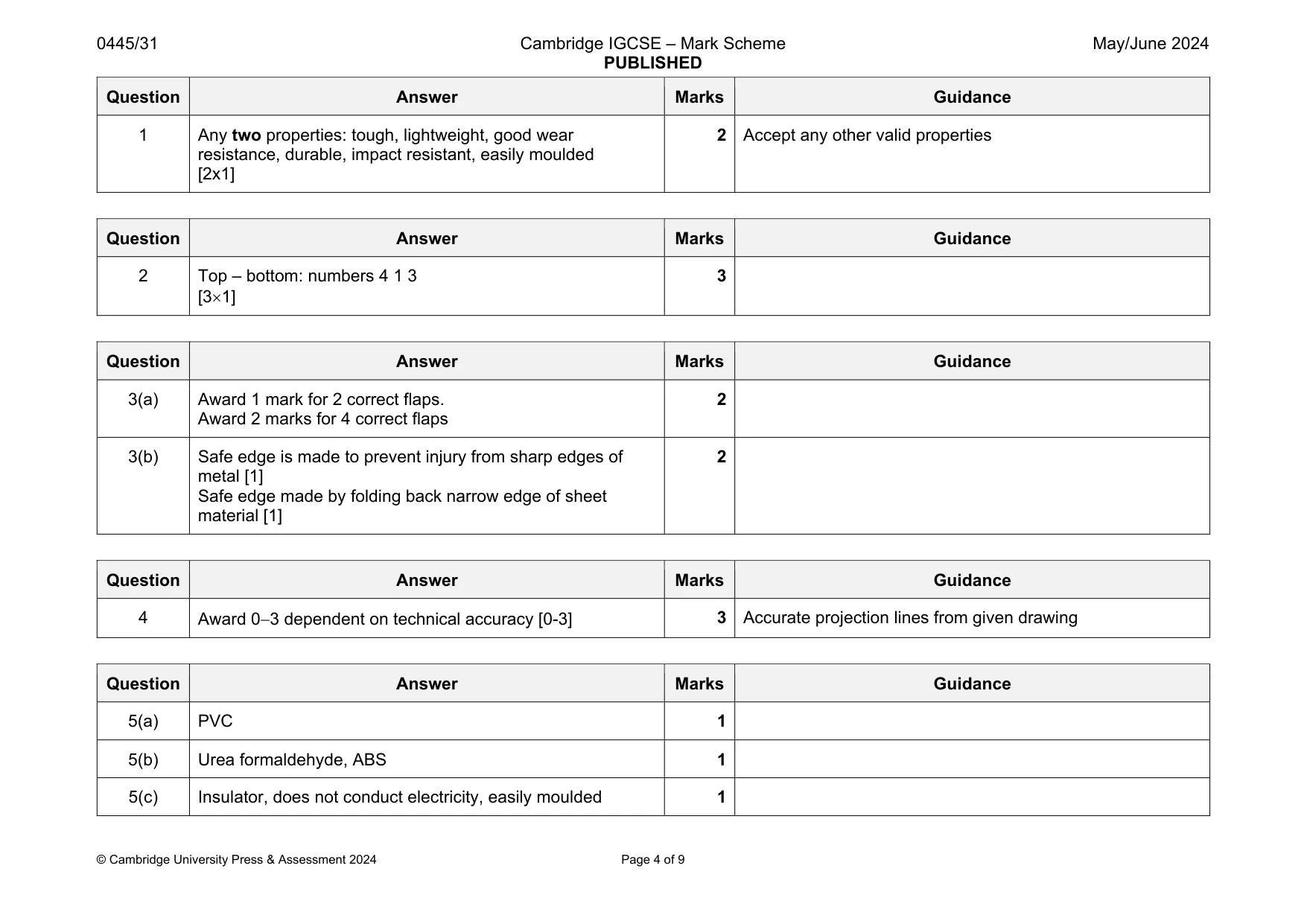
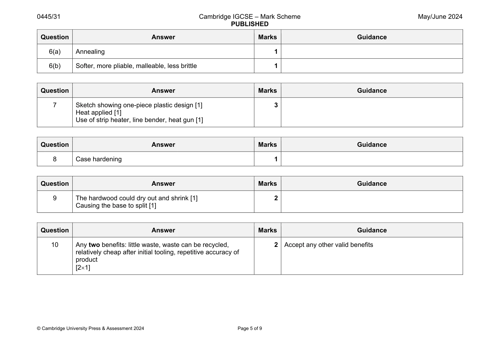
Mark scheme: 1 Any two properties: tough, lightweight, good wear resistance, durable, impact resistant, easily moulded [2x1] 2 Accept any other valid properties
Q2 · Three types of drill bit
2 Table 2.1 shows three types of drill bit. Table 2.1 Chosen Types of drill bit number 20 Complete Table 2.1 by adding the number from the list below to show the correct use for each drill bit. 1 used to drill smooth sided, flat bottomed holes 2 used in a centre lathe to start off a hole in metal 3 used for countersinking holes in wood and metal 4 used for fast drilling in wood 5 used to drill 20–75 mm diameter holes [3]
Mark scheme: 2 Top – bottom: numbers 4 1 3 [31] 3
Q3 · The outline shape and a development (net) for a tray made from 1.5 mm mild steel sheet
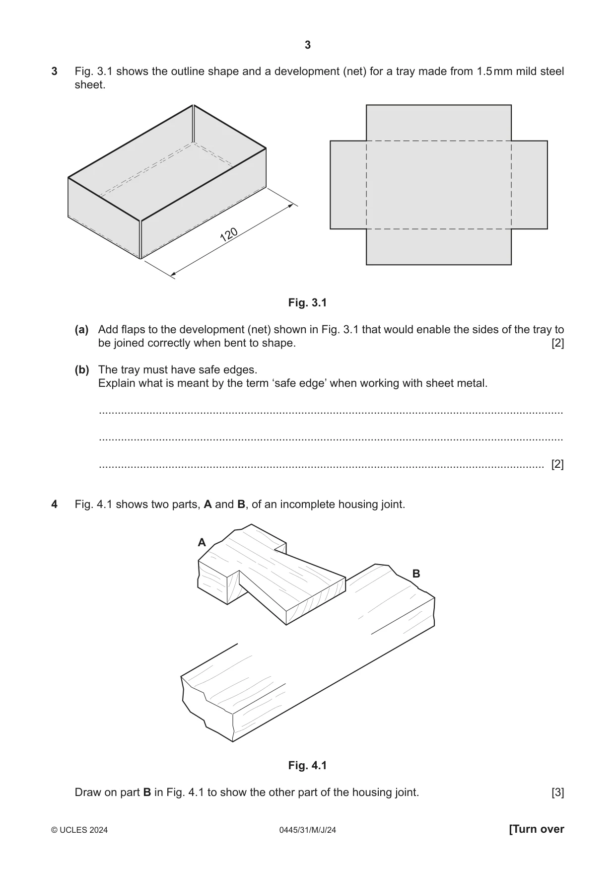
3 Fig. 3.1 shows the outline shape and a development (net) for a tray made from 1.5 mm mild steel sheet. 120 Fig. 3.1 (a) Add flaps to the development (net) shown in Fig. 3.1 that would enable the sides of the tray to be joined correctly when bent to shape. [2] (b) The tray must have safe edges. Explain what is meant by the term ‘safe edge’ when working with sheet metal. ................................................................................................................................................... ................................................................................................................................................... ............................................................................................................................................. [2]
Mark scheme: 3(a) Award 1 mark for 2 correct flaps. Award 2 marks for 4 correct flaps 2 3(b) Safe edge is made to prevent injury from sharp edges of metal [1] Safe edge made by folding back narrow edge of sheet material [1] 2
Q4 · Two parts, A and B, of an incomplete housing joint
4 Fig. 4.1 shows two parts, A and B, of an incomplete housing joint. A B Fig. 4.1 Draw on part B in Fig. 4.1 to show the other part of the housing joint. [3]
Mark scheme: 4 3 Accurate projection lines from given drawing
Q5 · An electrical plug with a length of electrical cable covered with plastic
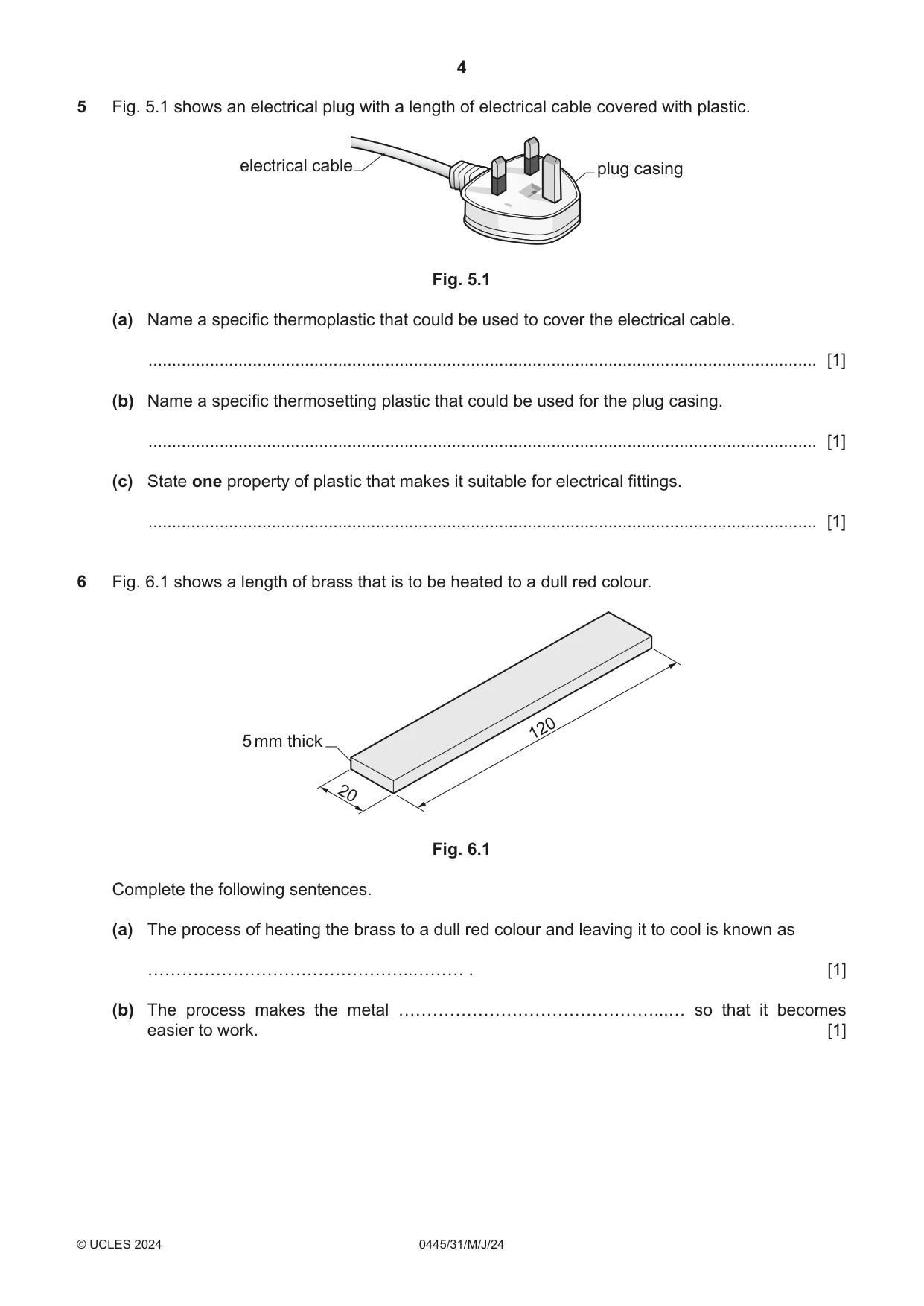
5 Fig. 5.1 shows an electrical plug with a length of electrical cable covered with plastic. electrical cable plug casing Fig. 5.1 (a) Name a specific thermoplastic that could be used to cover the electrical cable. ............................................................................................................................................. [1] (b) Name a specific thermosetting plastic that could be used for the plug casing. ............................................................................................................................................. [1] (c) State one property of plastic that makes it suitable for electrical fittings. ............................................................................................................................................. [1]
Mark scheme: 5(a) PVC 1 5(b) Urea formaldehyde, ABS 1 5(c) Insulator, does not conduct electricity, easily moulded 1
Q6 · A length of brass that is to be heated to a dull red colour
6 Fig. 6.1 shows a length of brass that is to be heated to a dull red colour. 120 5 mm thick 20 Fig. 6.1 Complete the following sentences. (a) The process of heating the brass to a dull red colour and leaving it to cool is known as [1] (b) The process makes the metal ………………………………………...… so that it becomes easier to work. [1]
Mark scheme: 6(a) Annealing 1 6(b) Softer, more pliable, malleable, less brittle 1
Q7 · A paint pot holder made of wood
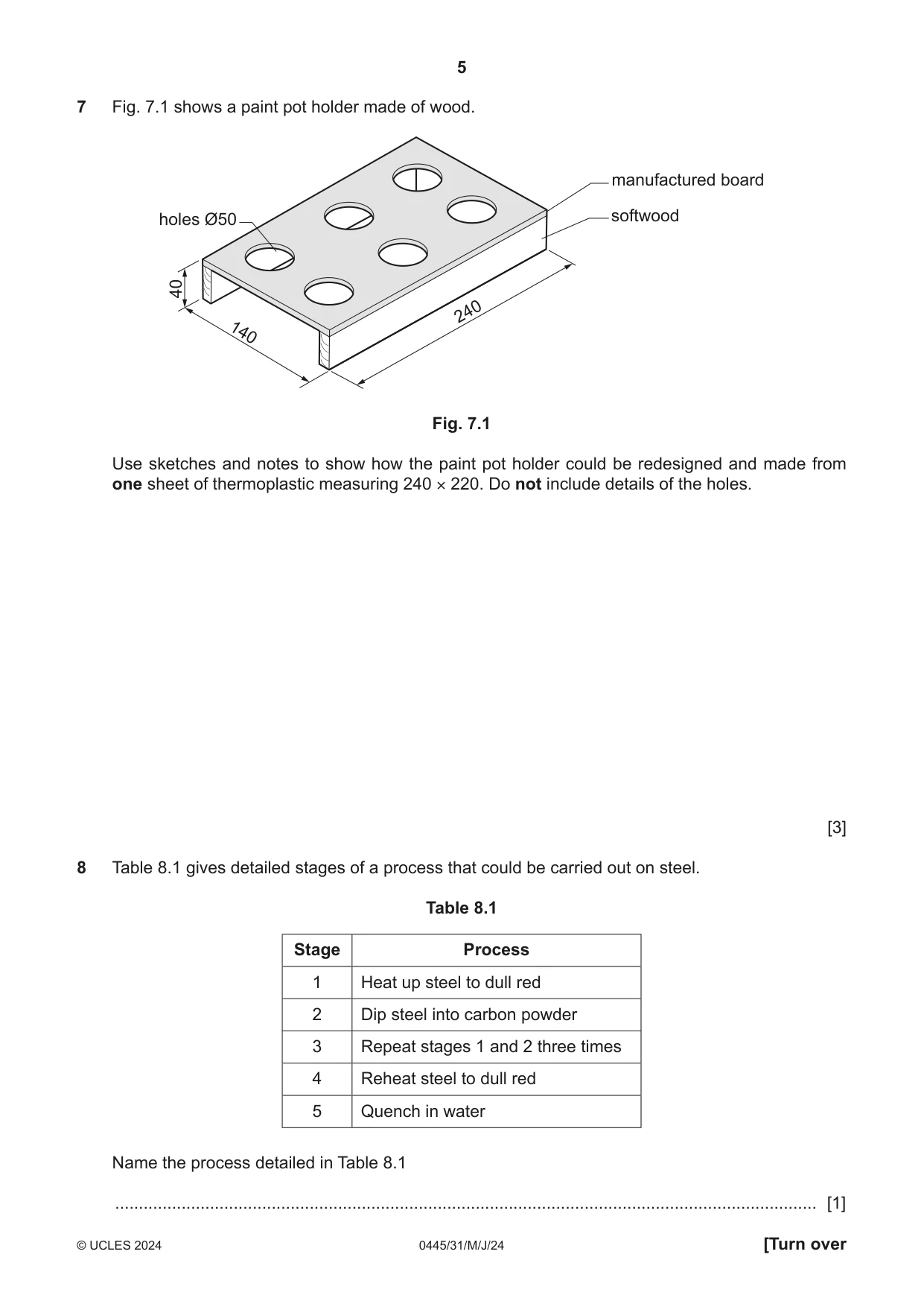
7 Fig. 7.1 shows a paint pot holder made of wood. manufactured board holes Ø50 softwood 40 240 140 Fig. 7.1 Use sketches and notes to show how the paint pot holder could be redesigned and made from one sheet of thermoplastic measuring 240 × 220. Do not include details of the holes. [3]
Mark scheme: 7 Sketch showing one-piece plastic design [1] Heat applied [1] Use of strip heater, line bender, heat gun [1] 3
Q8 · Detailed stages of a process that could be carried out on steel
8 Table 8.1 gives detailed stages of a process that could be carried out on steel. Table 8.1 Stage Process 1 Heat up steel to dull red 2 Dip steel into carbon powder 3 Repeat stages 1 and 2 three times 4 Reheat steel to dull red 5 Quench in water Name the process detailed in Table 8.1 .................................................................................................................................................... [1]
Mark scheme: 8 Case hardening 1
Q9 · Views of a small box made of hardwood
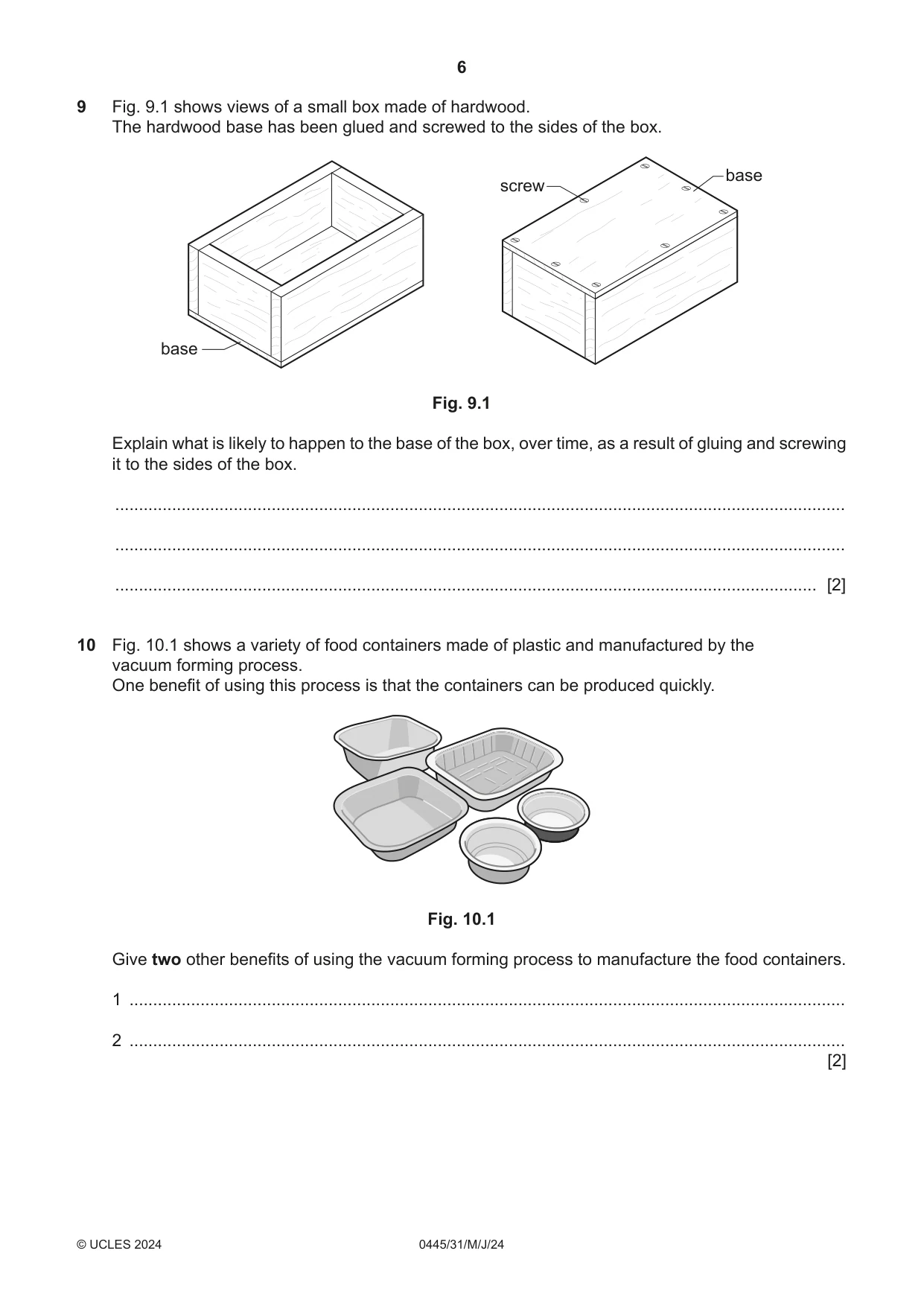
9 Fig. 9.1 shows views of a small box made of hardwood. The hardwood base has been glued and screwed to the sides of the box. base screw base Fig. 9.1 Explain what is likely to happen to the base of the box, over time, as a result of gluing and screwing it to the sides of the box. .......................................................................................................................................................... .......................................................................................................................................................... .................................................................................................................................................... [2]
Mark scheme: 9 The hardwood could dry out and shrink [1] Causing the base to split [1] 2
Q10 · A variety of food containers made of plastic and manufactured by the vacuum forming…
10 Fig. 10.1 shows a variety of food containers made of plastic and manufactured by the vacuum forming process. One benefit of using this process is that the containers can be produced quickly. Fig. 10.1 Give two other benefits of using the vacuum forming process to manufacture the food containers. 1 ....................................................................................................................................................... 2 ....................................................................................................................................................... [2]
Mark scheme: 10 Any two benefits: little waste, waste can be recycled, relatively cheap after initial tooling, repetitive accuracy of product [21]
Q11 · Views of an incomplete design for a teaching aid that could be used to teach children…
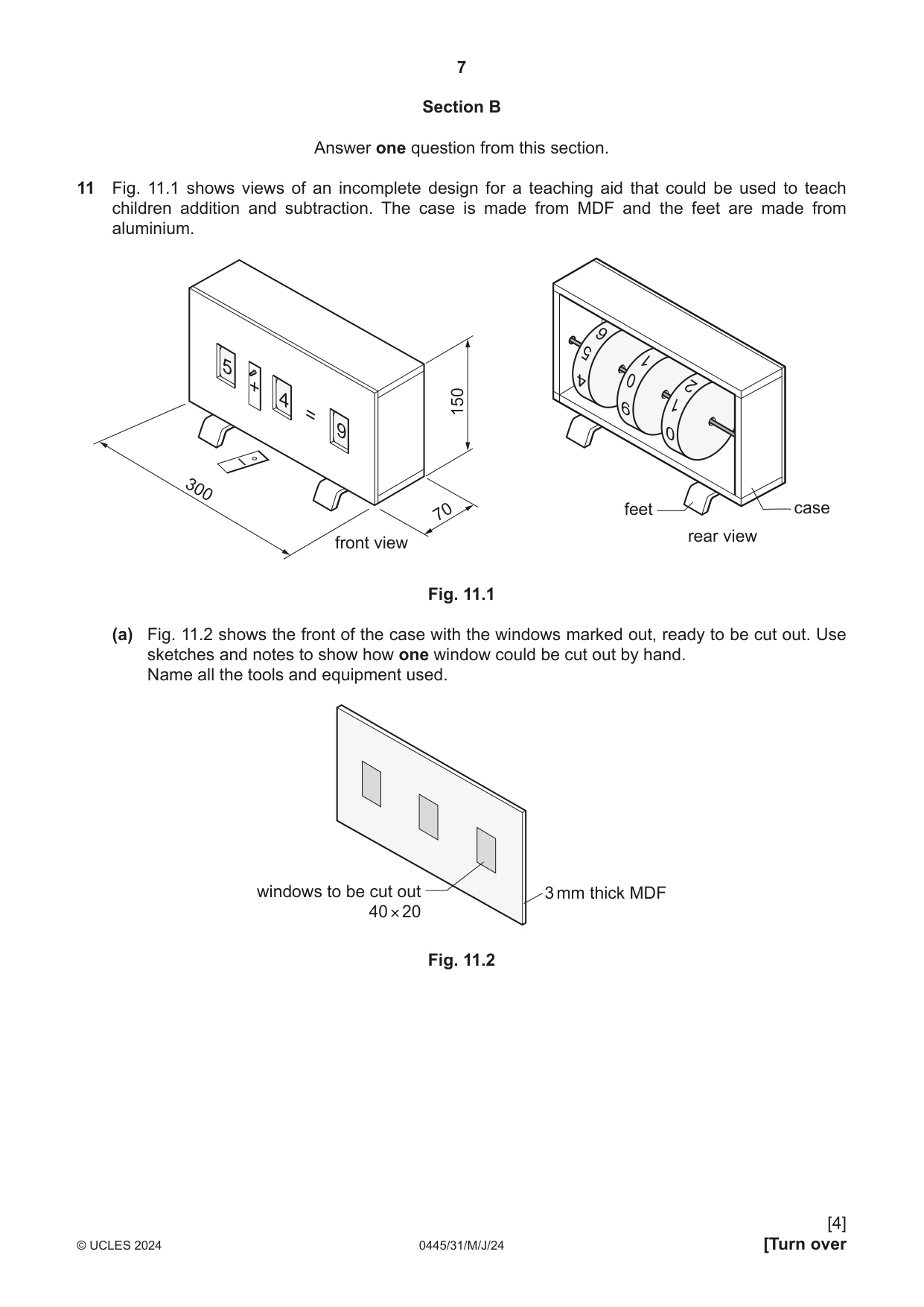
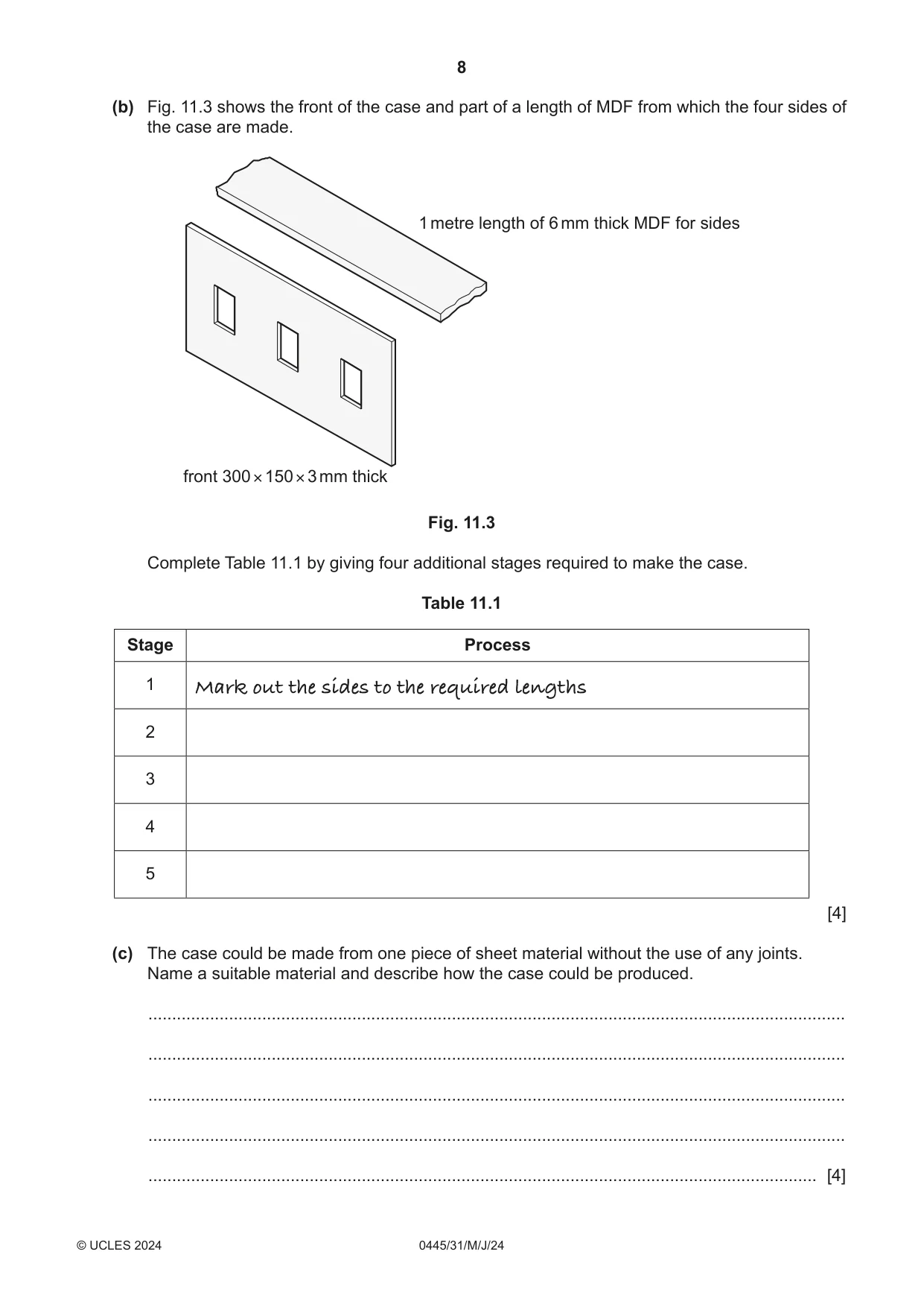
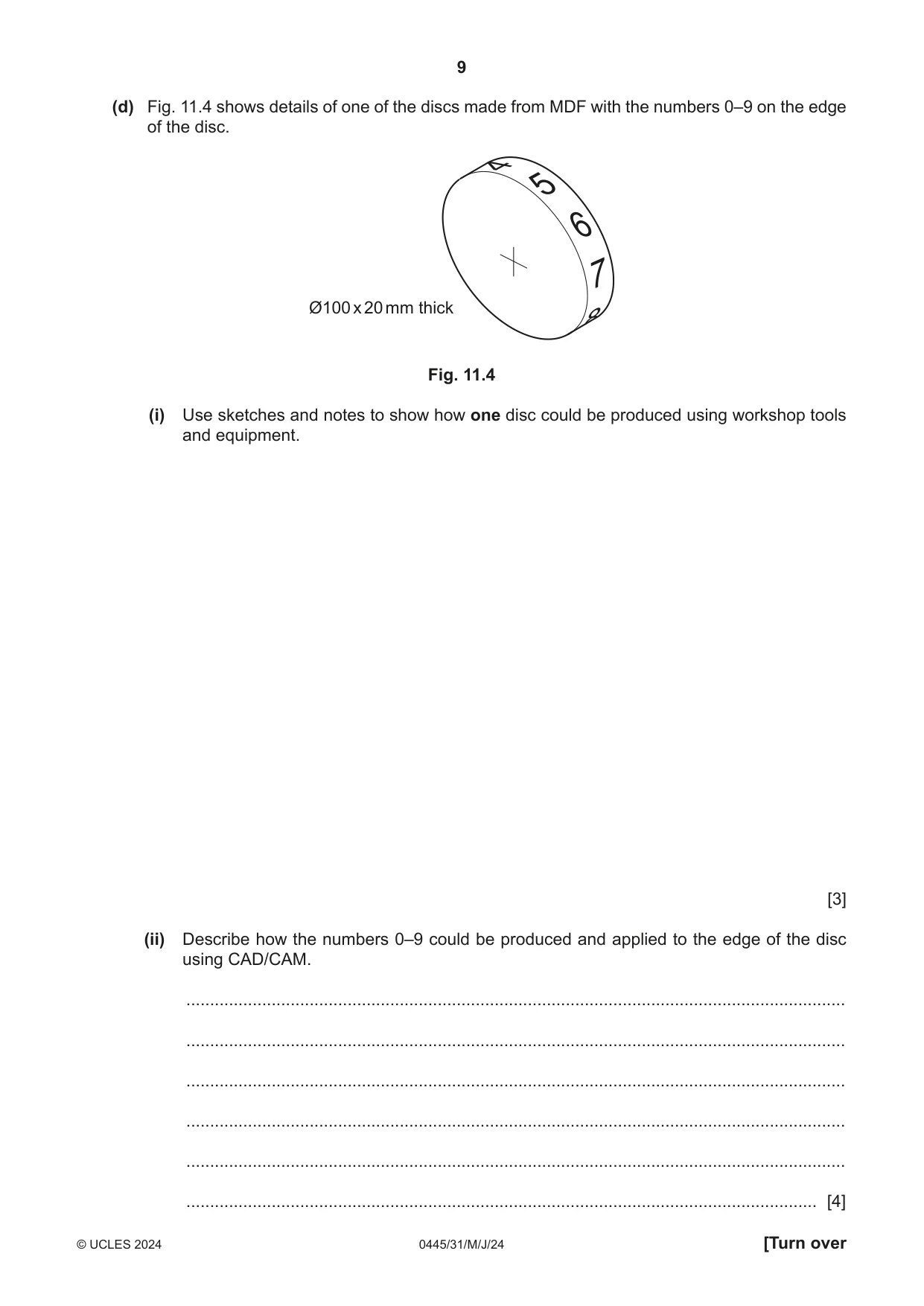
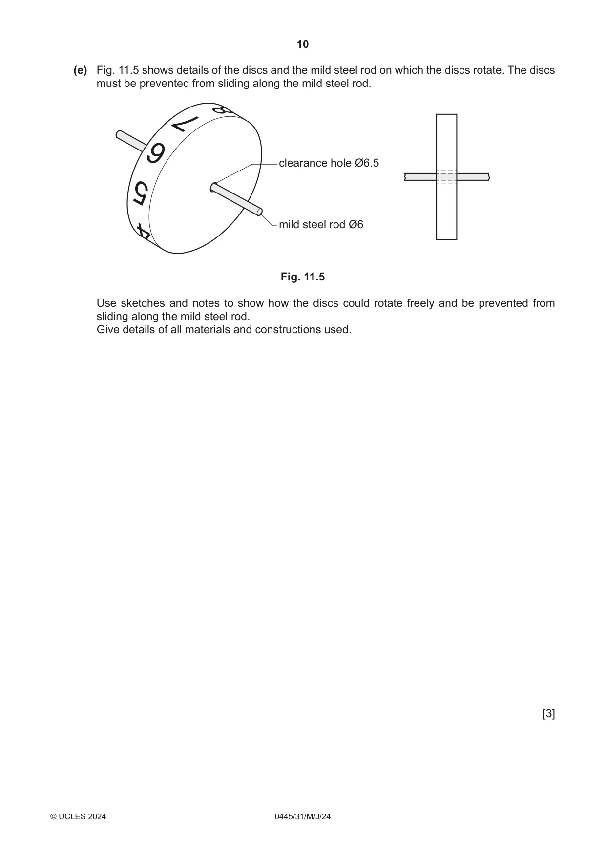
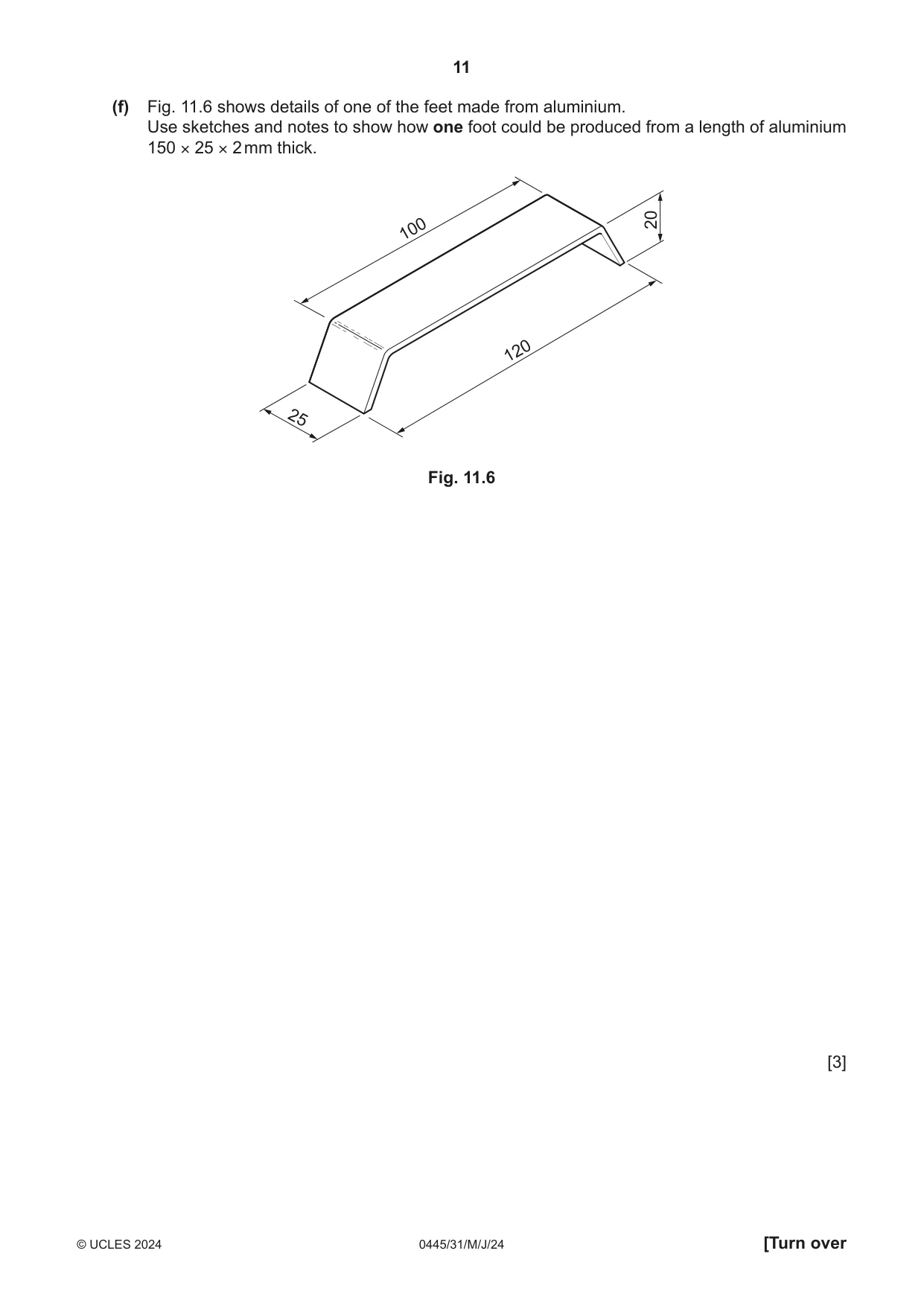
11 Fig. 11.1 shows views of an incomplete design for a teaching aid that could be used to teach children addition and subtraction. The case is made from MDF and the feet are made from aluminium. 6 5 5 1 + 4 0 2 4 150 9 1 = 9 0 – 300 70 feet case rear view front view Fig. 11.1 (a) Fig. 11.2 shows the front of the case with the windows marked out, ready to be cut out. Use sketches and notes to show how one window could be cut out by hand. Name all the tools and equipment used. windows to be cut out 3 mm thick MDF 40 × 20 Fig. 11.2 [4] (b) Fig. 11.3 shows the front of the case and part of a length of MDF from which the four sides of the case are made. 1 metre length of 6 mm thick MDF for sides front 300 × 150 × 3 mm thick Fig. 11.3 Complete Table 11.1 by giving four additional stages required to make the case. Table 11.1 Stage Process 1 Mark out the sides to the required lengths 2 3 4 5 [4] (c) The case could be made from one piece of sheet material without the use of any joints. Name a suitable material and describe how the case could be produced. ................................................................................................................................................... ................................................................................................................................................... ................................................................................................................................................... ................................................................................................................................................... ............................................................................................................................................. [4] (d) Fig. 11.4 shows details of one of the discs made from MDF with the numbers 0–9 on the edge of the disc. 5 6 7 Ø100 x 20 mm thick Fig. 11.4 (i) Use sketches and notes to show how one disc could be produced using workshop tools and equipment. [3] (ii) Describe how the numbers 0–9 could be produced and applied to the edge of the disc using CAD/CAM. ........................................................................................................................................... ........................................................................................................................................... ........................................................................................................................................... ........................................................................................................................................... ........................................................................................................................................... ..................................................................................................................................... [4] (e) Fig. 11.5 shows details of the discs and the mild steel rod on which the discs rotate. The discs must be prevented from sliding along the mild steel rod. 7 clearance hole Ø6.5 6 5 mild steel rod Ø6 Fig. 11.5 Use sketches and notes to show how the discs could rotate freely and be prevented from sliding along the mild steel rod. Give details of all materials and constructions used. [3] (f) Fig. 11.6 shows details of one of the feet made from aluminium. Use sketches and notes to show how one foot could be produced from a length of aluminium 150 × 25 × 2 mm thick. 100 20 120 25 Fig. 11.6 [3]
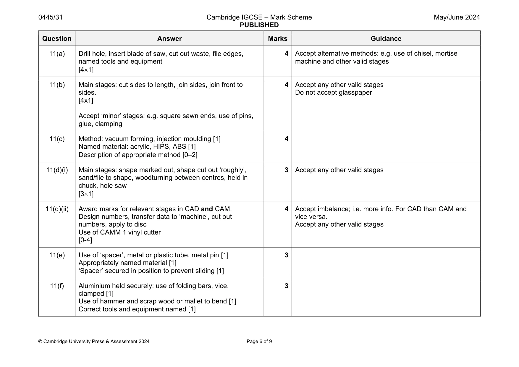
Mark scheme: 11(a) Drill hole, insert blade of saw, cut out waste, file edges, named tools and equipment [41] machine and other valid stages 11(b) Main stages: cut sides to length, join sides, join front to sides. [4x1] Accept ‘minor’ stages: e.g. square sawn ends, use of pins, glue, clamping 4 Accept any other valid stages Do not accept glasspaper 11(c) Method: vacuum forming, injection moulding [1] Named material: acrylic, HIPS, ABS [1] Description of appropriate method [02] 4 11(d)(i) Main stages: shape marked out, shape cut out ‘roughly’, sand/file to shape, woodturning between centres, held in chuck, hole saw [31] 3 Accept any other valid stages 11(d)(ii) Award marks for relevant stages in CAD and CAM. Design numbers, transfer data to ‘machine’, cut out numbers, apply to disc Use of CAMM 1 vinyl cutter [0-4] 4 Accept imbalance; i.e. more info. For CAD than CAM and vice versa. Accept any other valid stages 11(e) Use of ‘spacer’, metal or plastic tube, metal pin [1] Appropriately named material [1] ‘Spacer’ secured in position to prevent sliding [1] 3 11(f) Aluminium held securely: use of folding bars, vice, clamped [1] Use of hammer and scrap wood or mallet to bend [1] Correct tools and equipment named [1] 3
Q12 · An incomplete design for a unit to store items used in a shower room
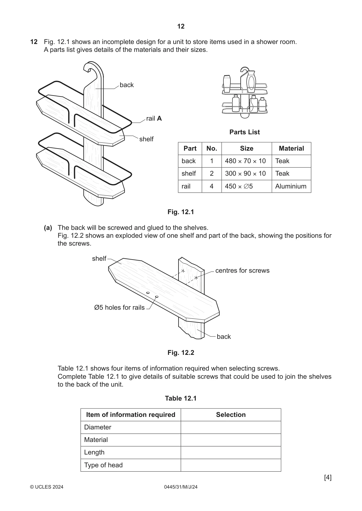
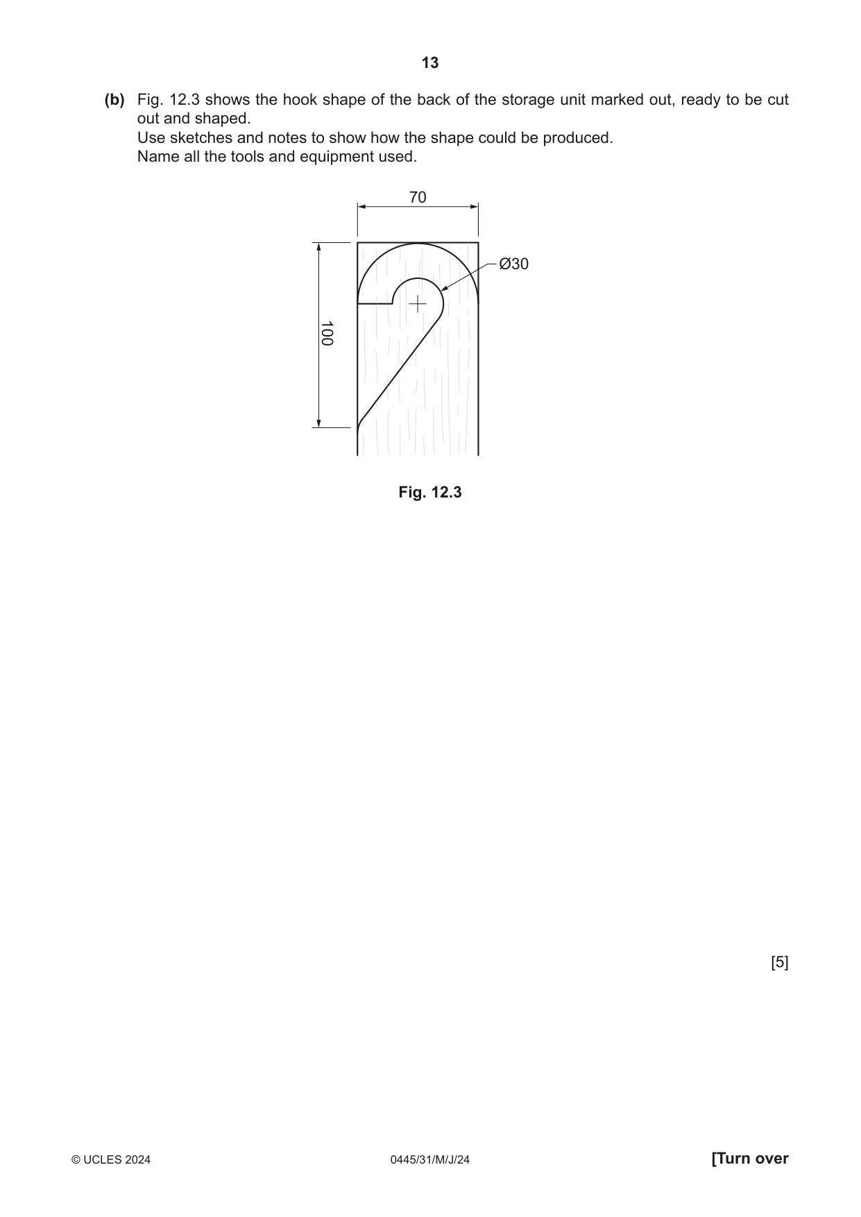
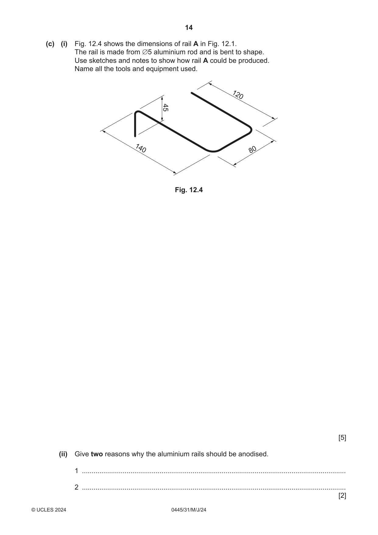
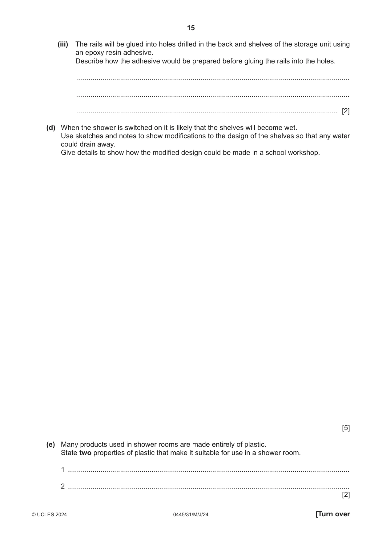
12 Fig. 12.1 shows an incomplete design for a unit to store items used in a shower room. A parts list gives details of the materials and their sizes. back rail A Parts List shelf Part No. Size Material back 1 480 × 70 × 10 Teak shelf 2 300 × 90 × 10 Teak rail 4 450 × ∅5 Aluminium Fig. 12.1 (a) The back will be screwed and glued to the shelves. Fig. 12.2 shows an exploded view of one shelf and part of the back, showing the positions for the screws. shelf centres for screws Ø5 holes for rails back Fig. 12.2 Table 12.1 shows four items of information required when selecting screws. Complete Table 12.1 to give details of suitable screws that could be used to join the shelves to the back of the unit. Table 12.1 Item of information required Selection Diameter Material Length Type of head [4] (b) Fig. 12.3 shows the hook shape of the back of the storage unit marked out, ready to be cut out and shaped. Use sketches and notes to show how the shape could be produced. Name all the tools and equipment used. 70 Ø30 100 Fig. 12.3 [5] (c) (i) Fig. 12.4 shows the dimensions of rail A in Fig. 12.1. The rail is made from ∅5 aluminium rod and is bent to shape. Use sketches and notes to show how rail A could be produced. Name all the tools and equipment used. 120 45 140 80 Fig. 12.4 [5] (ii) Give two reasons why the aluminium rails should be anodised. 1 ........................................................................................................................................ 2 ........................................................................................................................................ [2] (iii) The rails will be glued into holes drilled in the back and shelves of the storage unit using an epoxy resin adhesive. Describe how the adhesive would be prepared before gluing the rails into the holes. ........................................................................................................................................... ........................................................................................................................................... ..................................................................................................................................... [2] (d) When the shower is switched on it is likely that the shelves will become wet. Use sketches and notes to show modifications to the design of the shelves so that any water could drain away. Give details to show how the modified design could be made in a school workshop. [5] (e) Many products used in shower rooms are made entirely of plastic. State two properties of plastic that make it suitable for use in a shower room. 1 ................................................................................................................................................ 2 ................................................................................................................................................ [2]
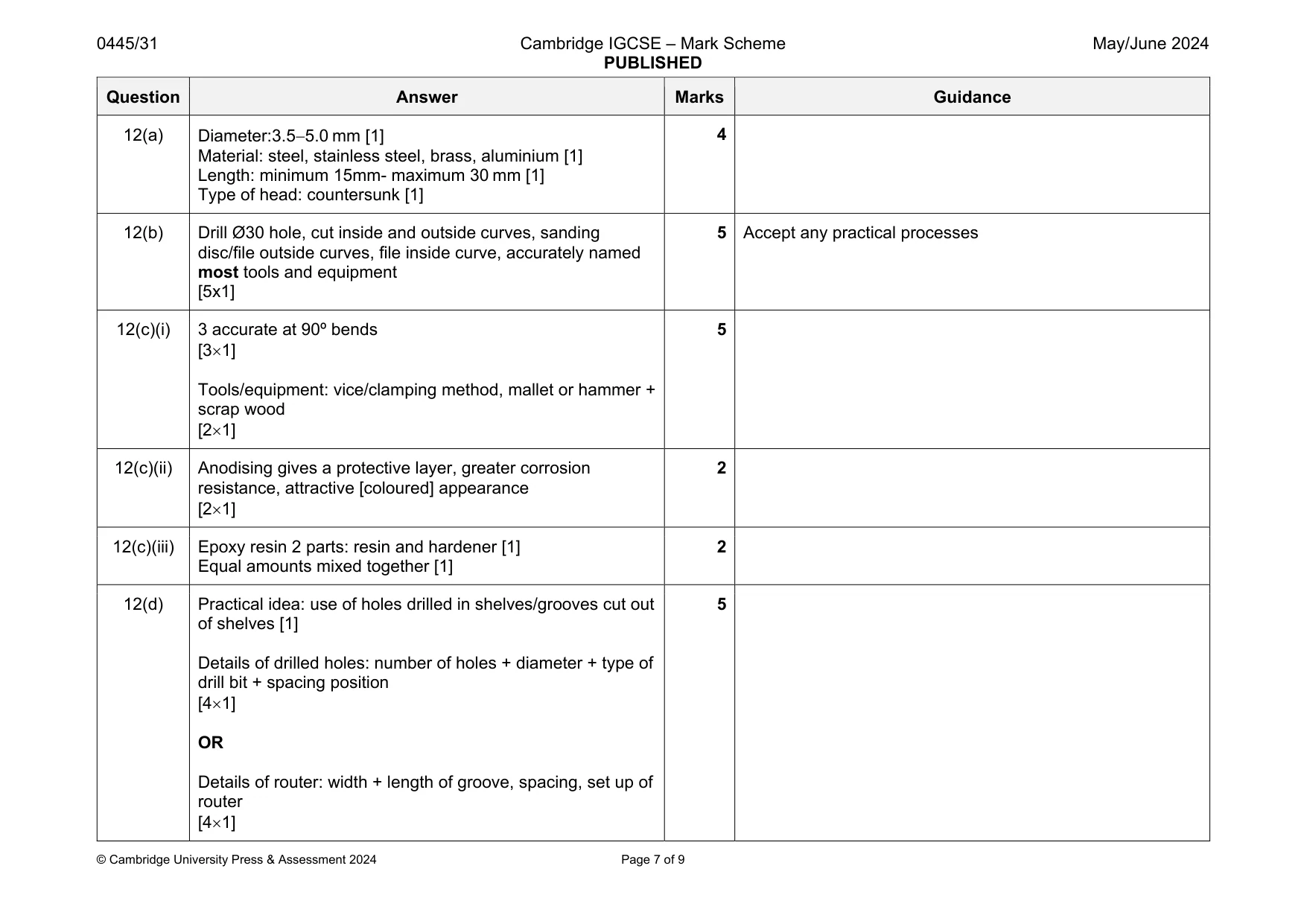
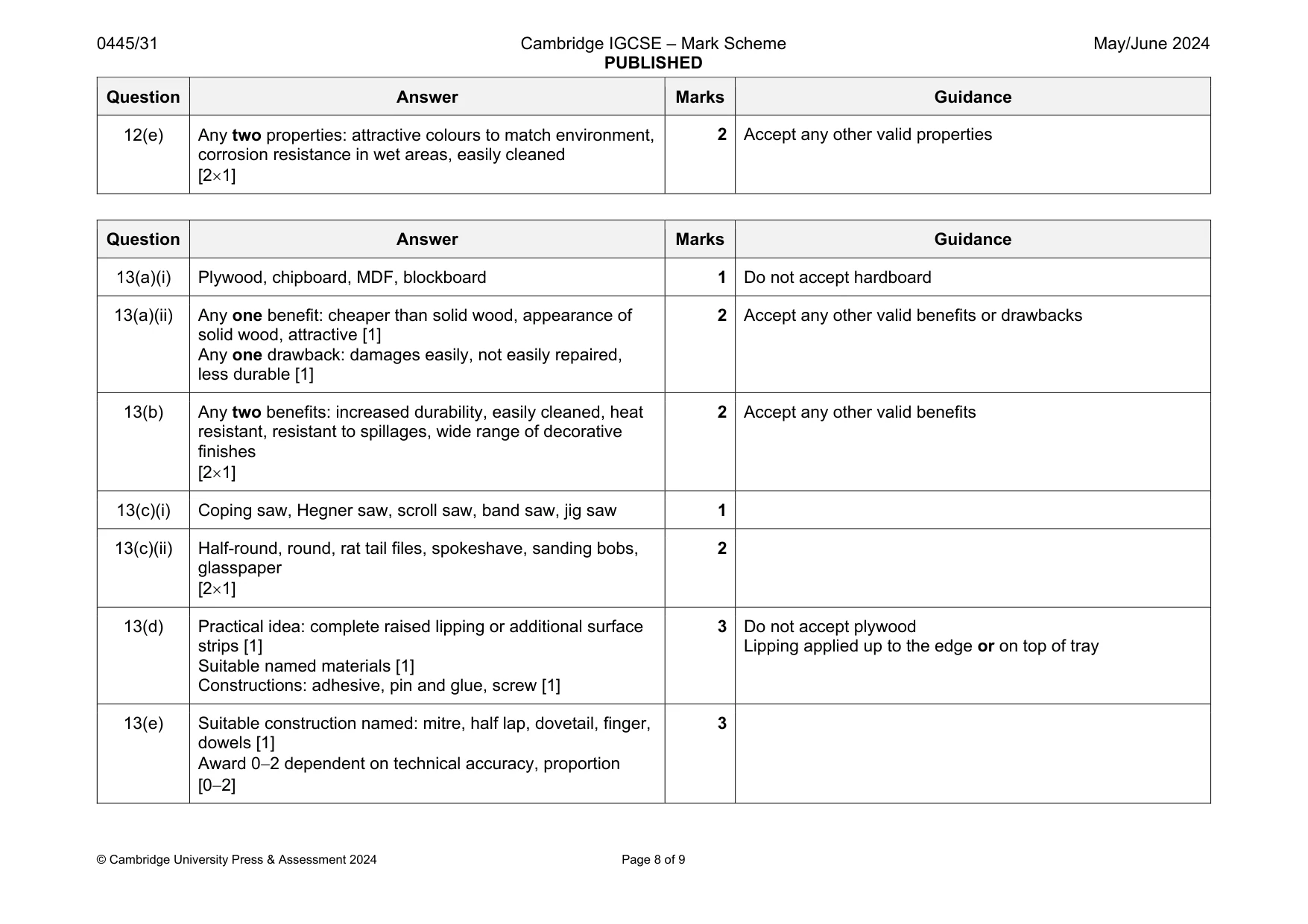
Mark scheme: 12(a) Material: steel, stainless steel, brass, aluminium [1] Length: minimum 15mm- maximum 30 mm [1] Type of head: countersunk [1] 12(b) Drill Ø30 hole, cut inside and outside curves, sanding disc/file outside curves, file inside curve, accurately named most tools and equipment [5x1] 5 Accept any practical processes 12(c)(i) 3 accurate at 90º bends [31] Tools/equipment: vice/clamping method, mallet or hammer + scrap wood [21] 5 12(c)(ii) Anodising gives a protective layer, greater corrosion resistance, attractive [coloured] appearance [21] 2 12(c)(iii) Epoxy resin 2 parts: resin and hardener [1] Equal amounts mixed together [1] 2 12(d) Practical idea: use of holes drilled in shelves/grooves cut out of shelves [1] Details of drilled holes: number of holes + diameter + type of drill bit + spacing position [41] OR Details of router: width + length of groove, spacing, set up of router [41] 5 Question Answer Marks Guidance 12(e) Any two properties: attractive colours to match environment, corrosion resistance in wet areas, easily cleaned [21] 2 Accept any other valid properties
Q13 · Views of an incomplete design for an adjustable tray that could be used by a person…
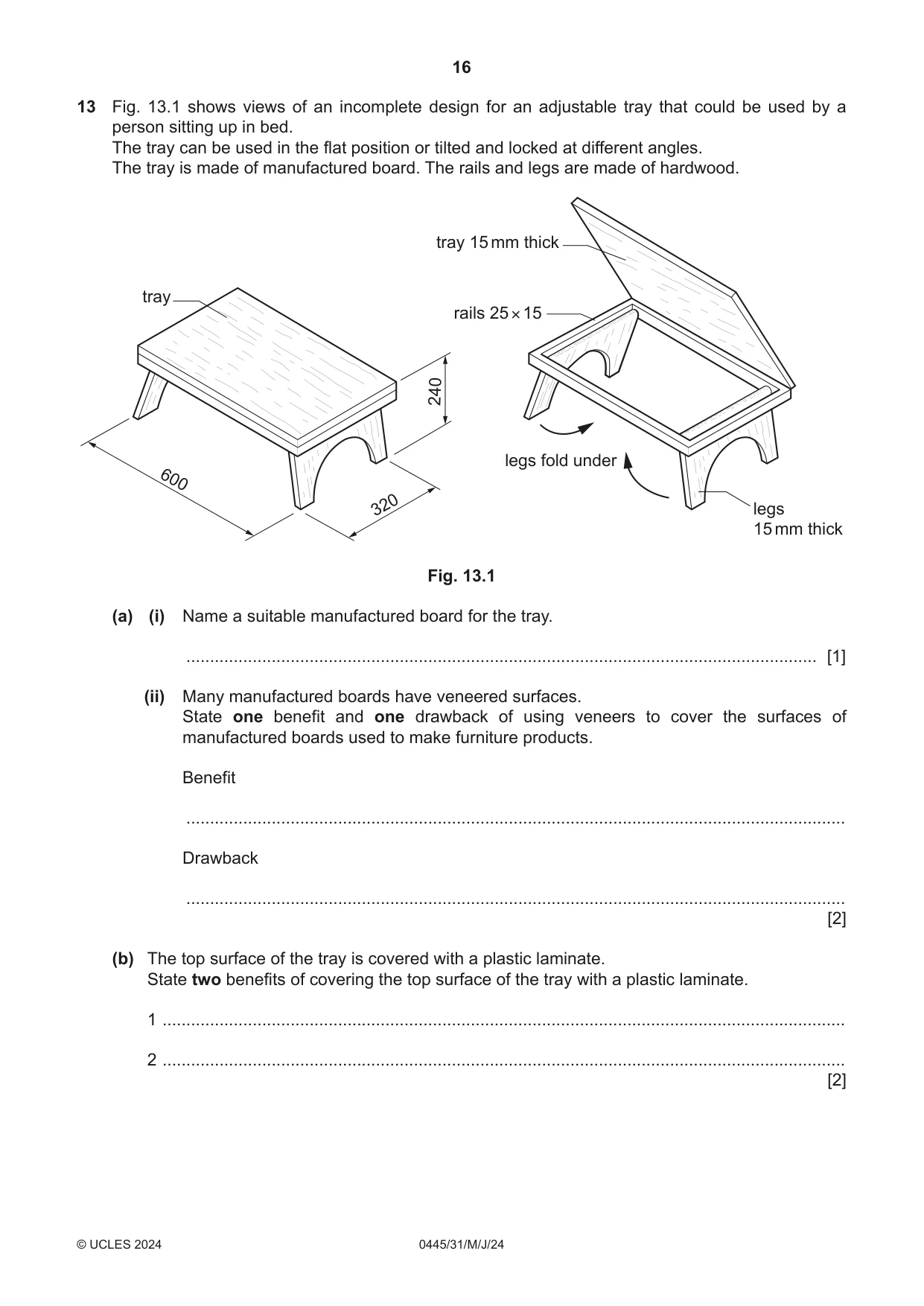
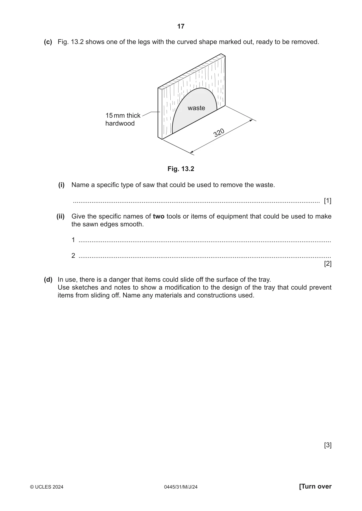
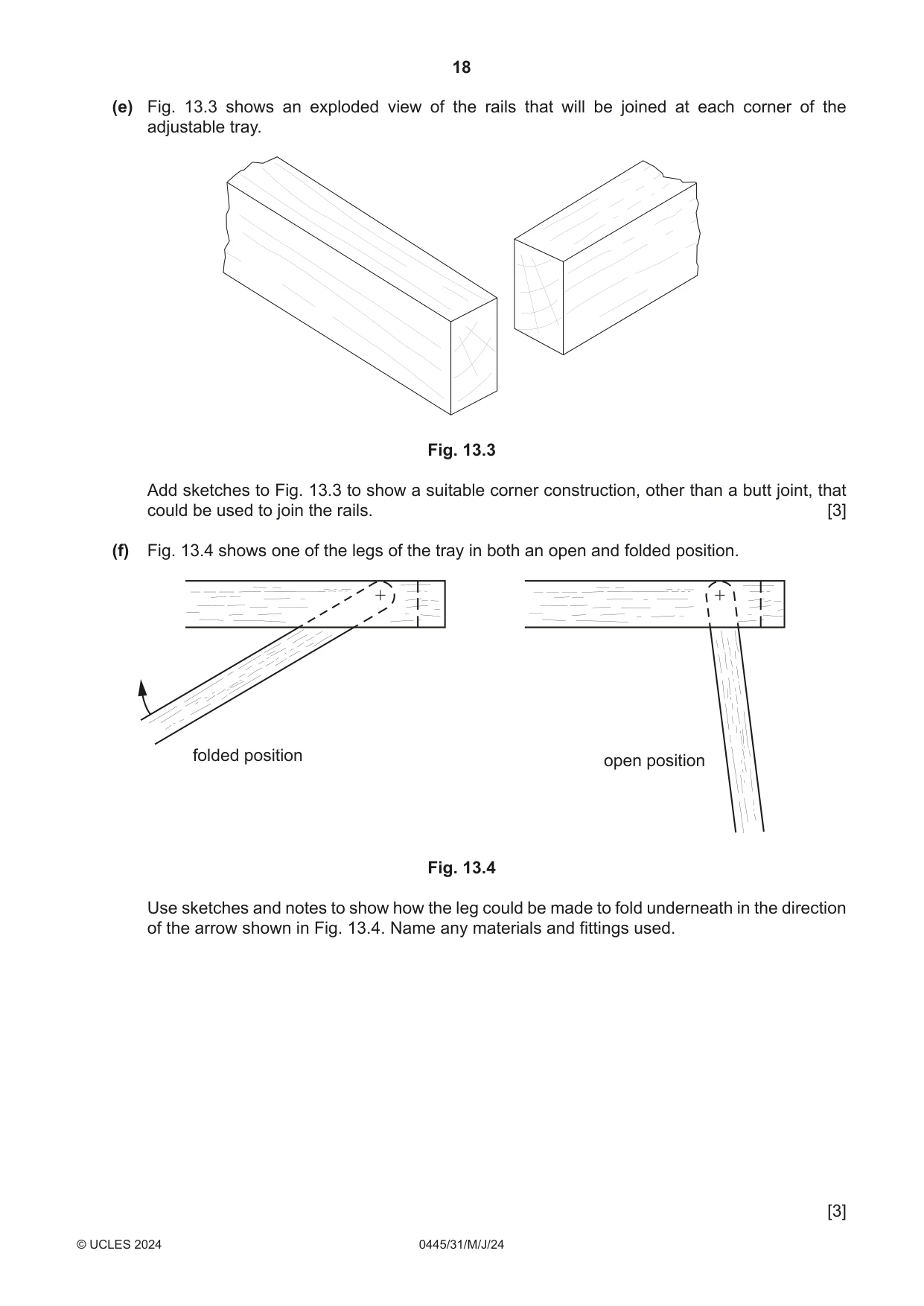
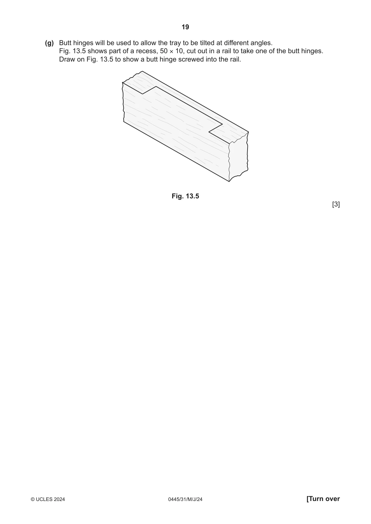
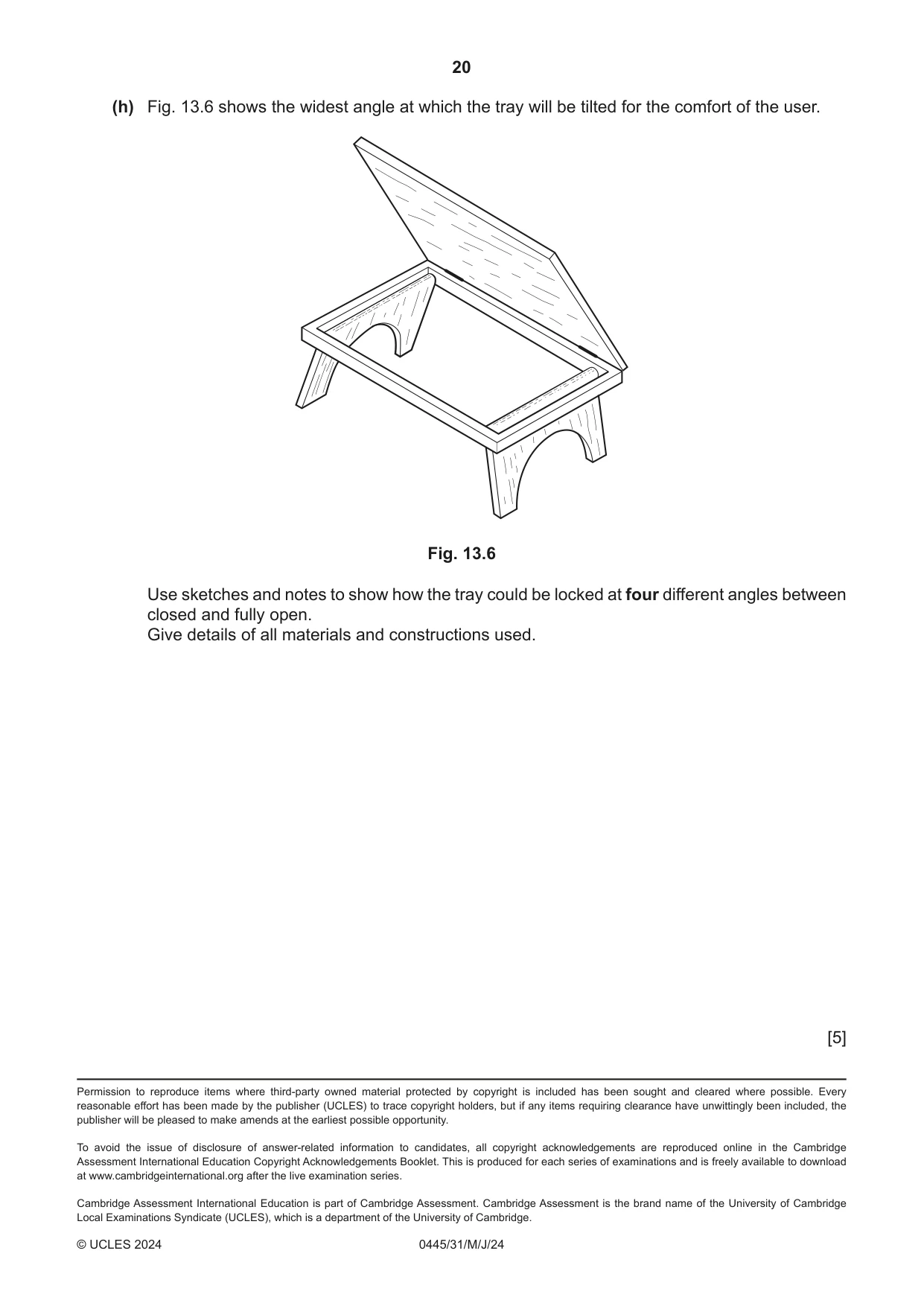
13 Fig. 13.1 shows views of an incomplete design for an adjustable tray that could be used by a person sitting up in bed. The tray can be used in the flat position or tilted and locked at different angles. The tray is made of manufactured board. The rails and legs are made of hardwood. tray 15 mm thick tray rails 25 × 15 240 legs fold under 600 320 legs 15 mm thick Fig. 13.1 (a) (i) Name a suitable manufactured board for the tray. ..................................................................................................................................... [1] (ii) Many manufactured boards have veneered surfaces. State one benefit and one drawback of using veneers to cover the surfaces of manufactured boards used to make furniture products. Benefit ........................................................................................................................................... Drawback ........................................................................................................................................... [2] (b) The top surface of the tray is covered with a plastic laminate. State two benefits of covering the top surface of the tray with a plastic laminate. 1 ................................................................................................................................................ 2 ................................................................................................................................................ [2] (c) Fig. 13.2 shows one of the legs with the curved shape marked out, ready to be removed. waste 15 mm thick hardwood 320 Fig. 13.2 (i) Name a specific type of saw that could be used to remove the waste. ..................................................................................................................................... [1] (ii) Give the specific names of two tools or items of equipment that could be used to make the sawn edges smooth. 1 ........................................................................................................................................ 2 ........................................................................................................................................ [2] (d) In use, there is a danger that items could slide off the surface of the tray. Use sketches and notes to show a modification to the design of the tray that could prevent items from sliding off. Name any materials and constructions used. [3] (e) Fig. 13.3 shows an exploded view of the rails that will be joined at each corner of the adjustable tray. Fig. 13.3 Add sketches to Fig. 13.3 to show a suitable corner construction, other than a butt joint, that could be used to join the rails. [3] (f) Fig. 13.4 shows one of the legs of the tray in both an open and folded position. folded position open position Fig. 13.4 Use sketches and notes to show how the leg could be made to fold underneath in the direction of the arrow shown in Fig. 13.4. Name any materials and fittings used. [3]
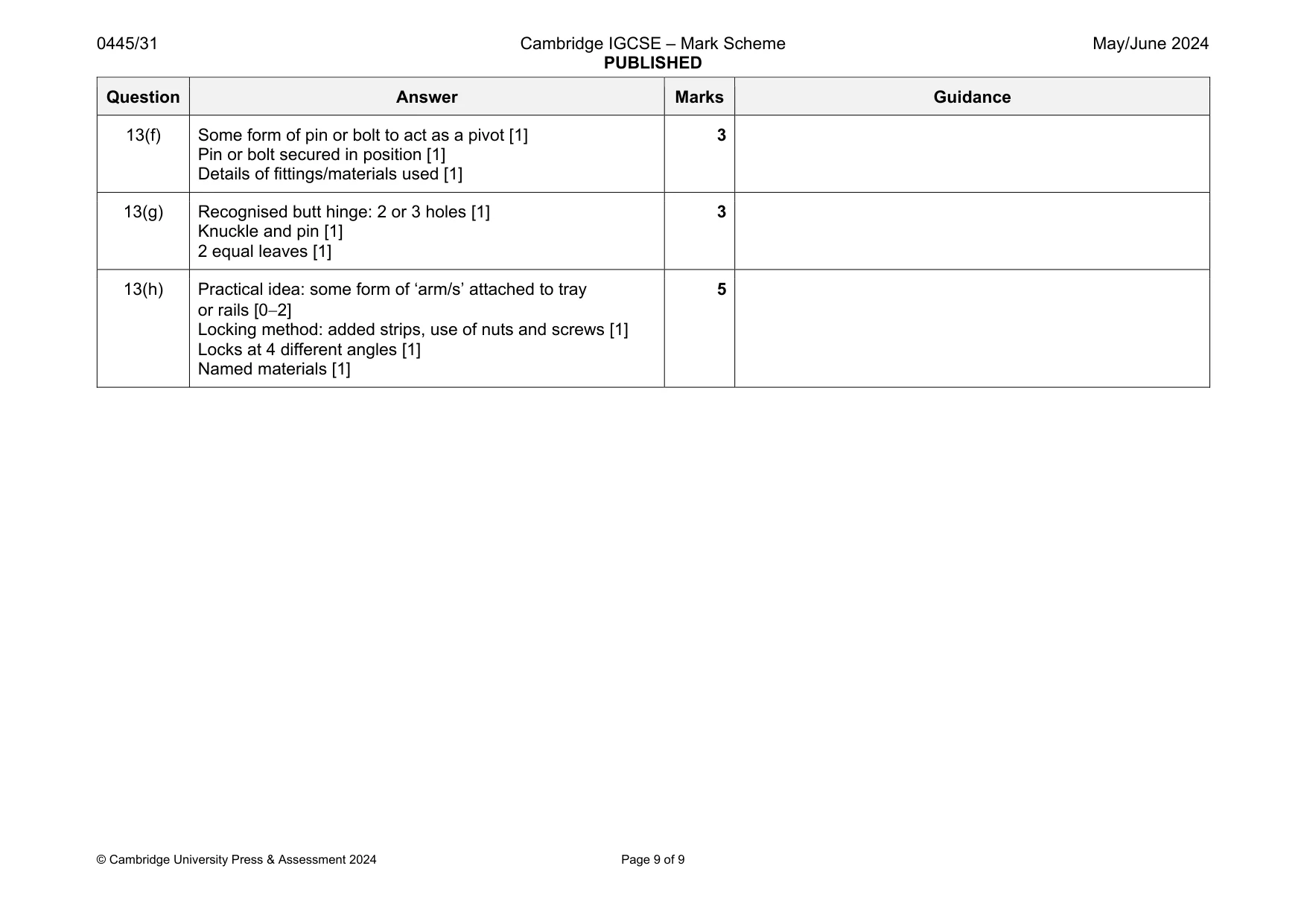
Mark scheme: 13(a)(i) Plywood, chipboard, MDF, blockboard 1 Do not accept hardboard 13(a)(ii) Any one benefit: cheaper than solid wood, appearance of solid wood, attractive [1] Any one drawback: damages easily, not easily repaired, less durable [1] 2 Accept any other valid benefits or drawbacks 13(b) Any two benefits: increased durability, easily cleaned, heat resistant, resistant to spillages, wide range of decorative finishes [21] 2 Accept any other valid benefits 13(c)(i) Coping saw, Hegner saw, scroll saw, band saw, jig saw 1 13(c)(ii) Half-round, round, rat tail files, spokeshave, sanding bobs, glasspaper [21] 2 13(d) Practical idea: complete raised lipping or additional surface strips [1] Suitable named materials [1] Constructions: adhesive, pin and glue, screw [1] 3 Do not accept plywood Lipping applied up to the edge or on top of tray 13(e) Suitable construction named: mitre, half lap, dovetail, finger, dowels [1] Award 02 dependent on technical accuracy, proportion [02] 3 Question Answer Marks Guidance 13(f) Some form of pin or bolt to act as a pivot [1] Pin or bolt secured in position [1] Details of fittings/materials used [1] 3 13(g) Recognised butt hinge: 2 or 3 holes [1] Knuckle and pin [1] 2 equal leaves [1] 3 13(h) Practical idea: some form of ‘arm/s’ attached to tray or rails [02] Locking method: added strips, use of nuts and screws [1] Locks at 4 different angles [1] Named materials [1] 5
What was in this paper
The subtopics covered by these 13 questions, and how many questions each got. Open one in a new tab to see every Cambridge question on it.
What you needed in this session
Cambridge’s own grade thresholds for 2024 May/June, Paper 3 · Variant 1. A higher threshold means an easier paper — the bar moves with how the cohort did.