Cambridge IGCSE Design and Technology 0445 — 2023 Oct/Nov Paper 3 · Variant 2
0445/32/O/N/23 · 13 questions · 50 marks · ≈56 min
The question paper and its mark scheme, free to read here and free to download. This is Cambridge’s own paper, exactly as it was sat.
Question paper24 pages
Mark scheme11 pages
Answers below. Sit the paper first if you are practising.
Questions as text
Question 1
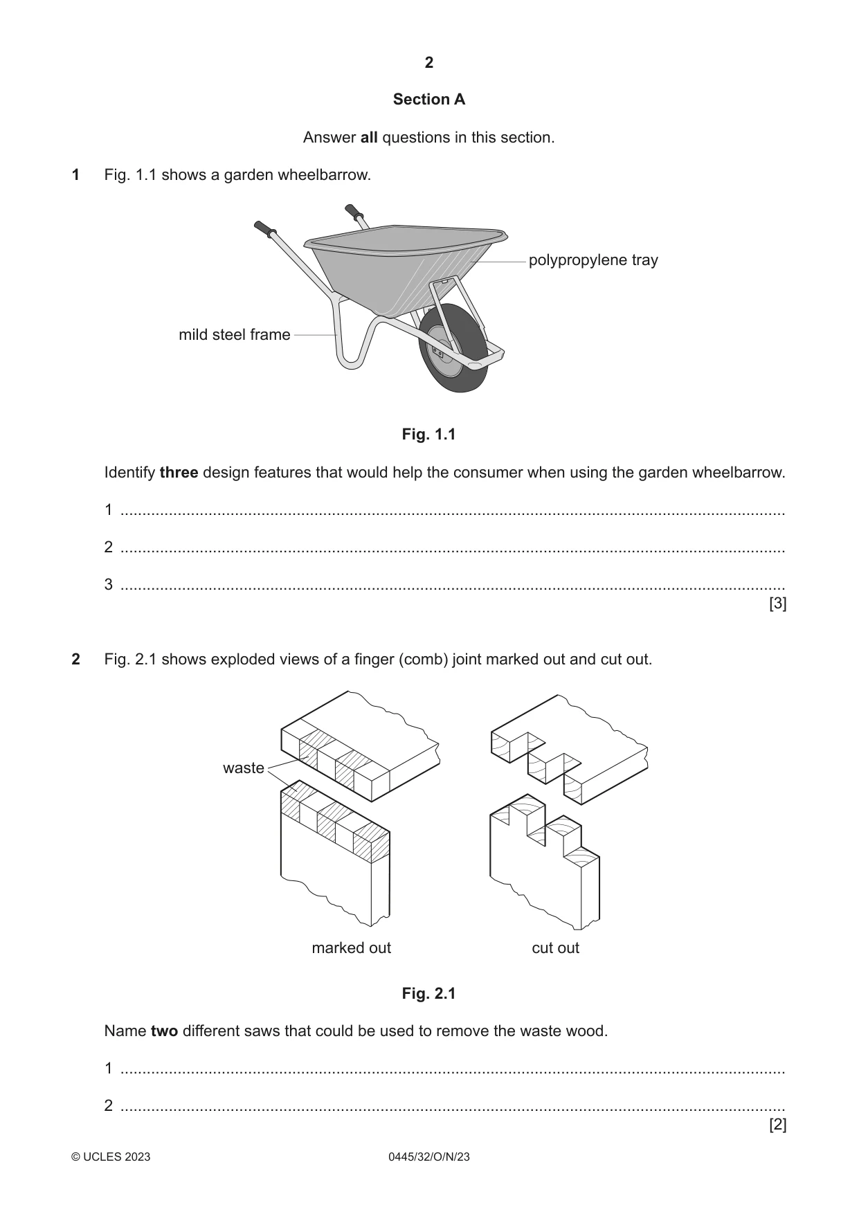
1 Fig. 1.1 shows a garden wheelbarrow. polypropylene tray mild steel frame Fig. 1.1 Identify three design features that would help the consumer when using the garden wheelbarrow. 1 ....................................................................................................................................................... 2 ....................................................................................................................................................... 3 ....................................................................................................................................................... [3]
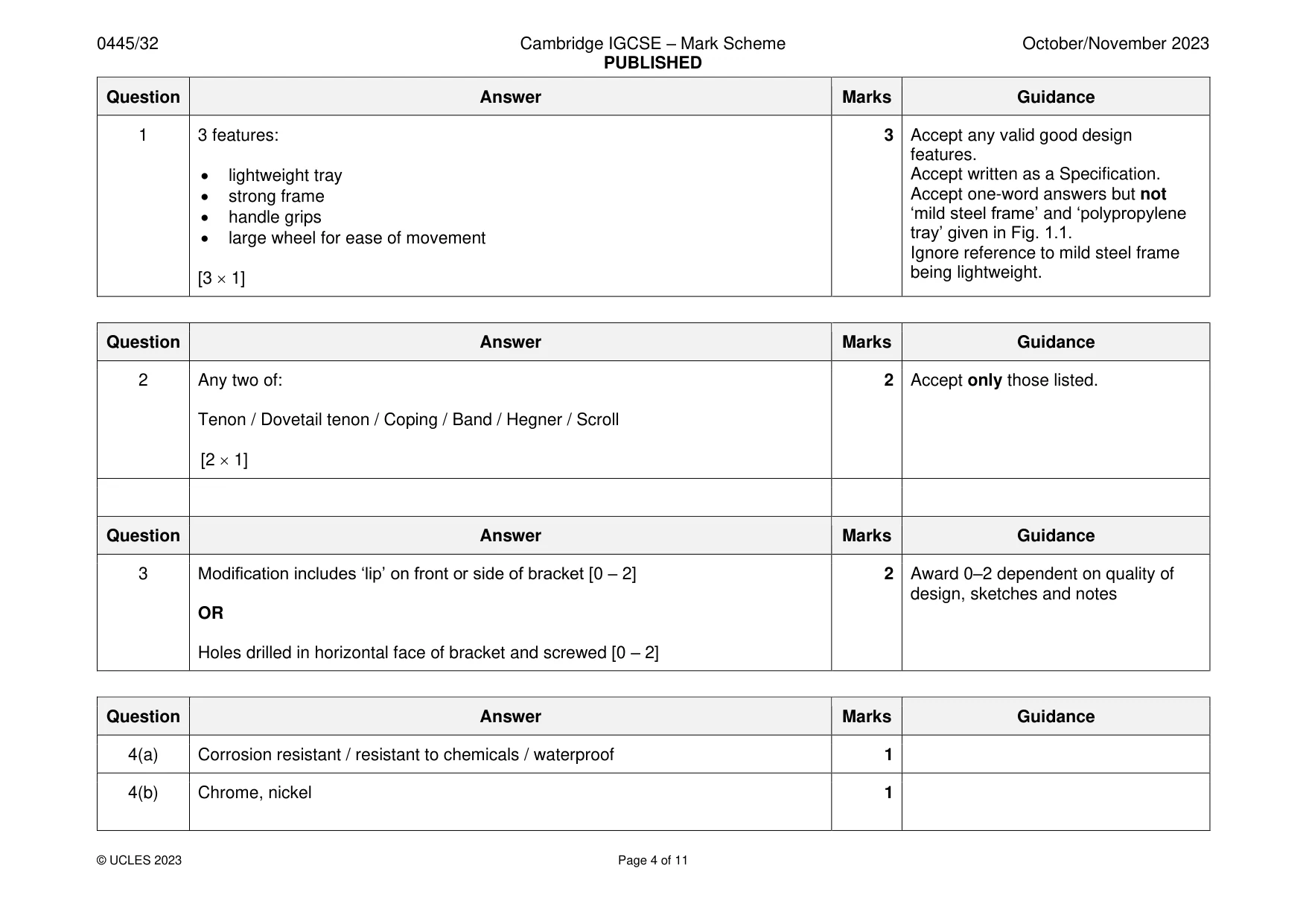
Mark scheme: Question Answer Marks Guidance 1 3 features: 3 Accept any valid good design features. • lightweight tray Accept written as a Specification. • strong frame Accept one-word answers but not • handle grips ‘mild steel frame’ and ‘polypropylene • large wheel for ease of movement tray’ given in Fig. 1.1. Ignore reference to mild steel frame being lightweight. [3 1]
Q2 · Exploded views of a finger (comb) joint marked out and cut out
2 Fig. 2.1 shows exploded views of a finger (comb) joint marked out and cut out. waste marked out cut out Fig. 2.1 Name two different saws that could be used to remove the waste wood. 1 ....................................................................................................................................................... 2 ....................................................................................................................................................... [2]
Mark scheme: 2 Any two of: 2 Accept only those listed. Tenon / Dovetail tenon / Coping / Band / Hegner / Scroll [2 1]
Q3 · Two parts of a shelving system
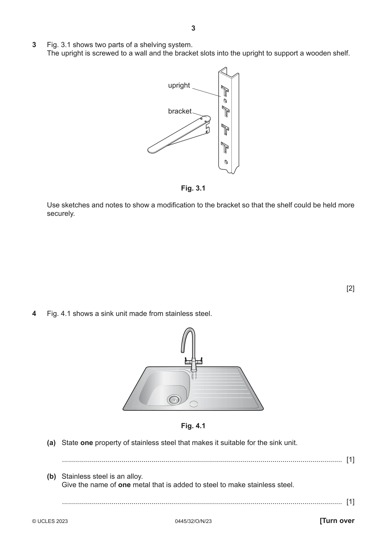
3 Fig. 3.1 shows two parts of a shelving system. The upright is screwed to a wall and the bracket slots into the upright to support a wooden shelf. upright bracket Fig. 3.1 Use sketches and notes to show a modification to the bracket so that the shelf could be held more securely. [2]
Mark scheme: 3 Modification includes ‘lip’ on front or side of bracket [0 – 2] 2 Award 0–2 dependent on quality of design, sketches and notes OR Holes drilled in horizontal face of bracket and screwed [0 – 2]
Q4 · A sink unit made from stainless steel
4 Fig. 4.1 shows a sink unit made from stainless steel. Fig. 4.1 (a) State one property of stainless steel that makes it suitable for the sink unit. ............................................................................................................................................. [1] (b) Stainless steel is an alloy. Give the name of one metal that is added to steel to make stainless steel. ............................................................................................................................................. [1]
Mark scheme: 4(a) Corrosion resistant / resistant to chemicals / waterproof 1 4(b) Chrome, nickel 1
Q5 · A gate fixed to a wall
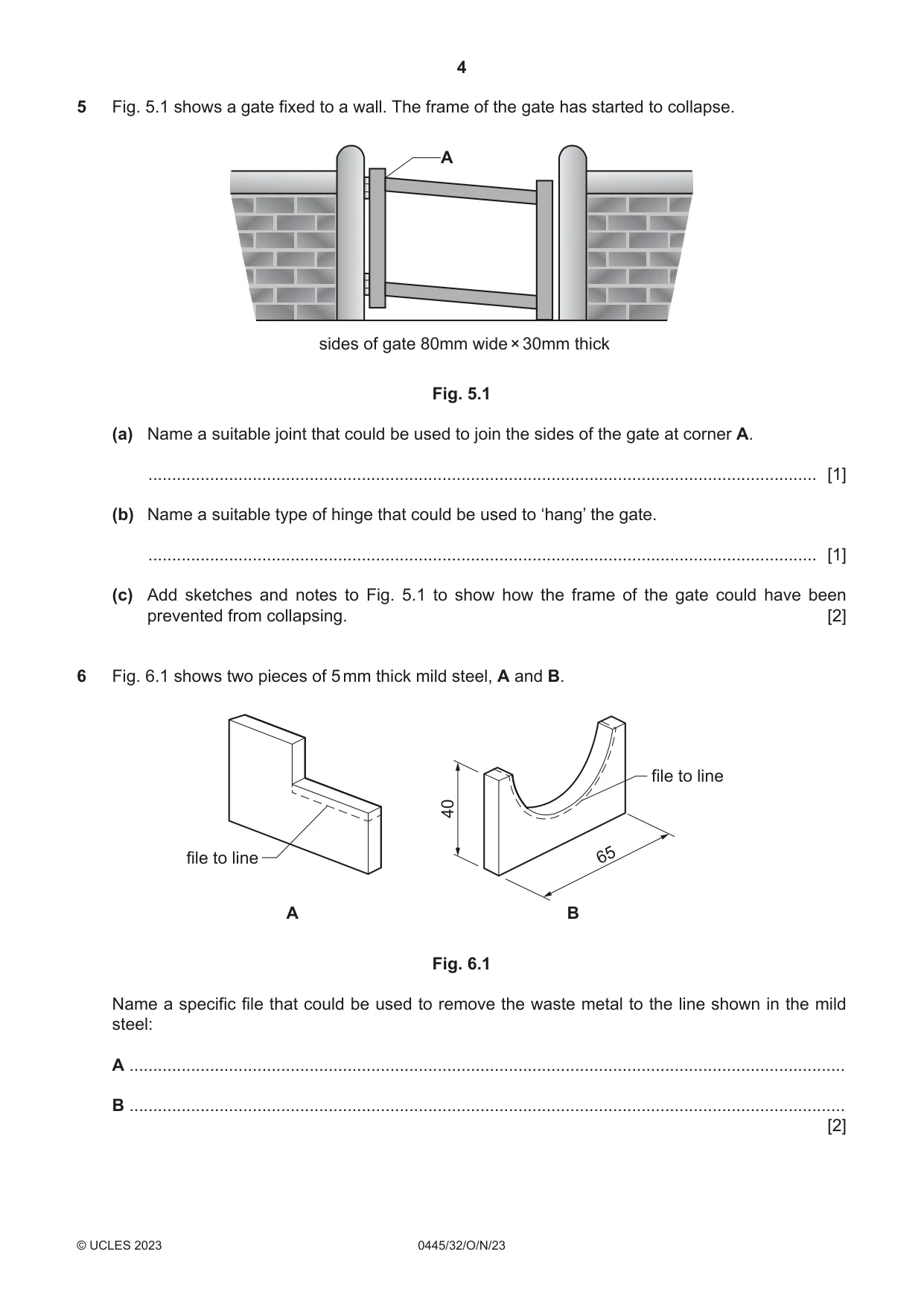
5 Fig. 5.1 shows a gate fixed to a wall. The frame of the gate has started to collapse. A sides of gate 80mm wide × 30mm thick Fig. 5.1 (a) Name a suitable joint that could be used to join the sides of the gate at corner A. ............................................................................................................................................. [1] (b) Name a suitable type of hinge that could be used to ‘hang’ the gate. ............................................................................................................................................. [1] (c) Add sketches and notes to Fig. 5.1 to show how the frame of the gate could have been prevented from collapsing. [2]
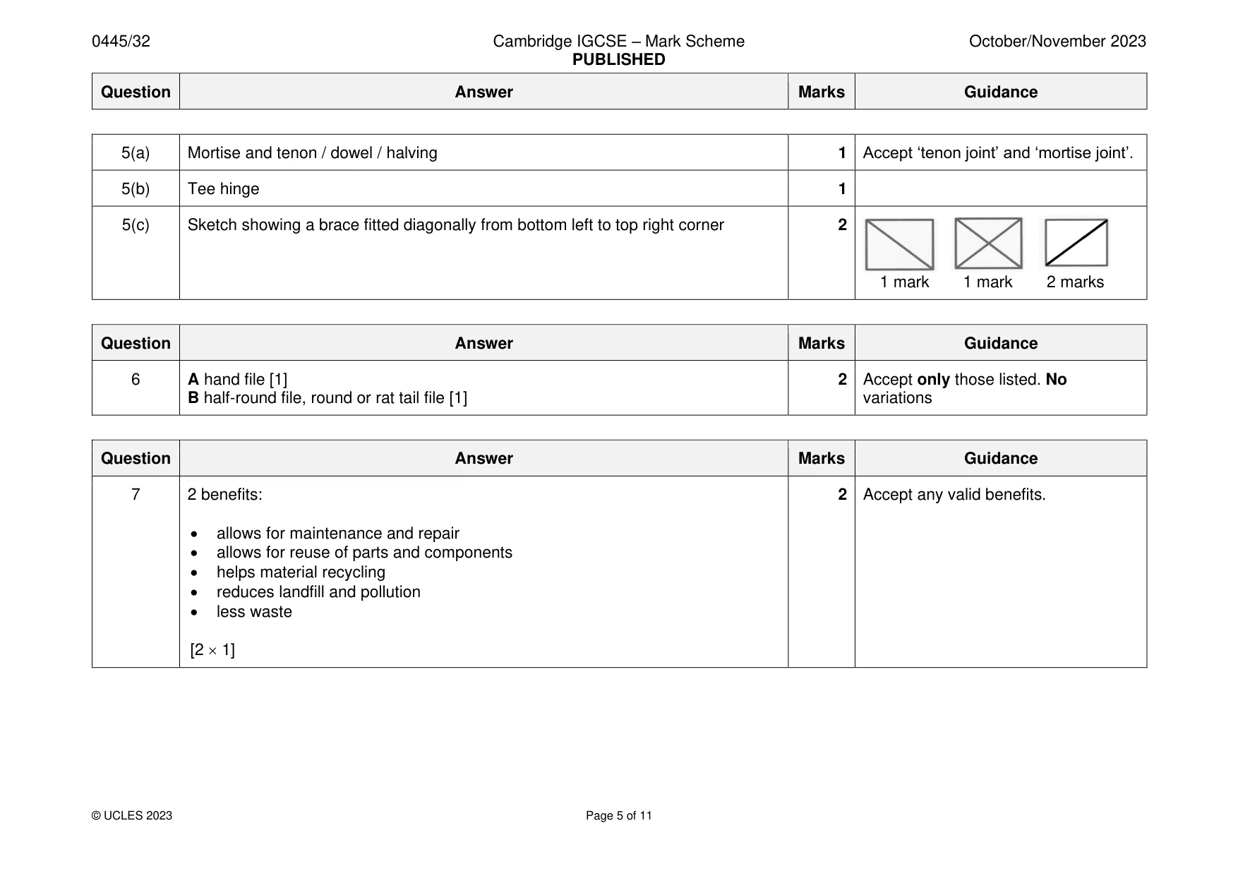
Mark scheme: 5(a) Mortise and tenon / dowel / halving 1 Accept ‘tenon joint’ and ‘mortise joint’. 5(b) Tee hinge 1 5(c) Sketch showing a brace fitted diagonally from bottom left to top right corner 2 1 mark 1 mark 2 marks
Q6 · Two pieces of 5 mm thick mild steel, A and B
6 Fig. 6.1 shows two pieces of 5 mm thick mild steel, A and B. file to line 40 file to line 65 A B Fig. 6.1 Name a specific file that could be used to remove the waste metal to the line shown in the mild steel: A ....................................................................................................................................................... B ....................................................................................................................................................... [2]
Mark scheme: 6 A hand file [1] 2 Accept only those listed. No B half-round file, round or rat tail file [1] variations
Q7 · An exploded view of a hand-held torch showing the different parts
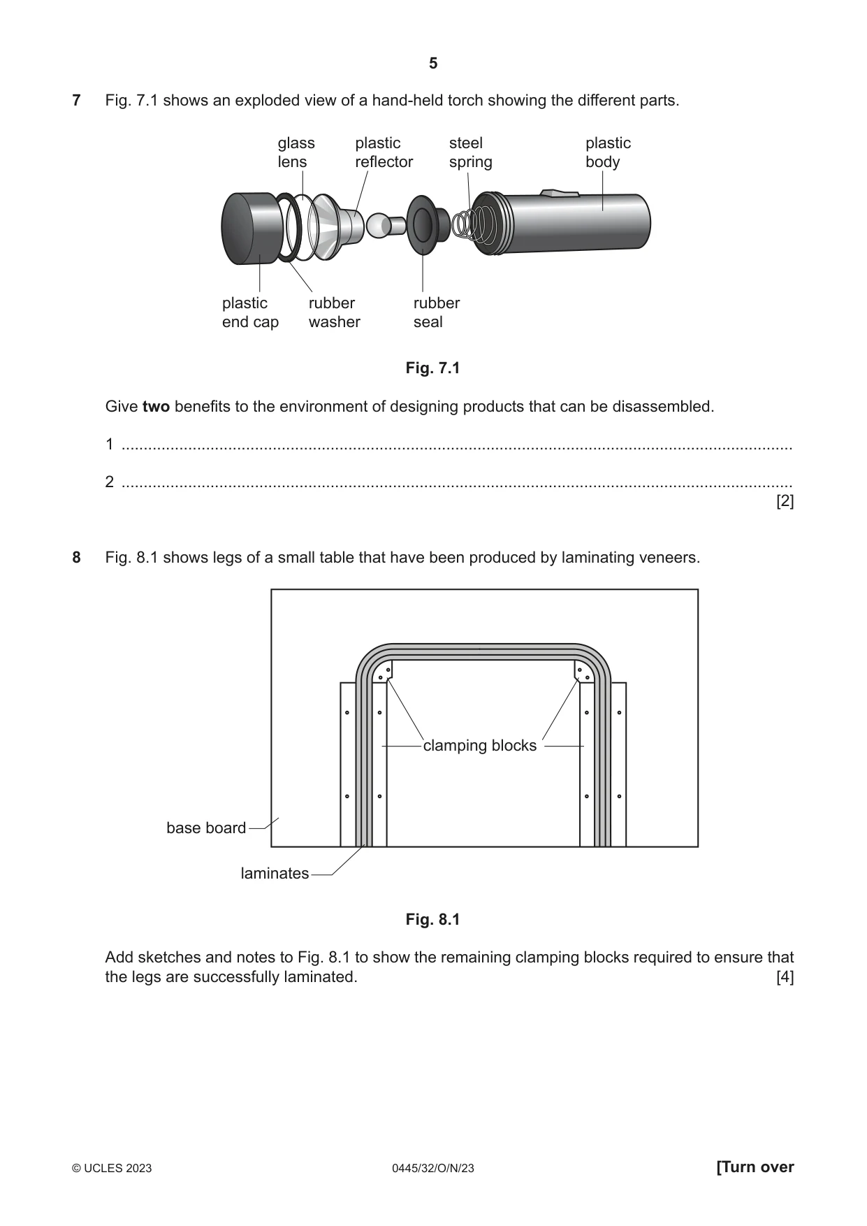
7 Fig. 7.1 shows an exploded view of a hand-held torch showing the different parts. glass plastic steel plastic lens reflector spring body plastic rubber rubber end cap washer seal Fig. 7.1 Give two benefits to the environment of designing products that can be disassembled. 1 ....................................................................................................................................................... 2 ....................................................................................................................................................... [2]
Mark scheme: 7 2 benefits: 2 Accept any valid benefits. • allows for maintenance and repair • allows for reuse of parts and components • helps material recycling • reduces landfill and pollution • less waste [2 1]
Q8 · Legs of a small table that have been produced by laminating veneers
8 Fig. 8.1 shows legs of a small table that have been produced by laminating veneers. clamping blocks base board laminates Fig. 8.1 Add sketches and notes to Fig. 8.1 to show the remaining clamping blocks required to ensure that the legs are successfully laminated. [4]
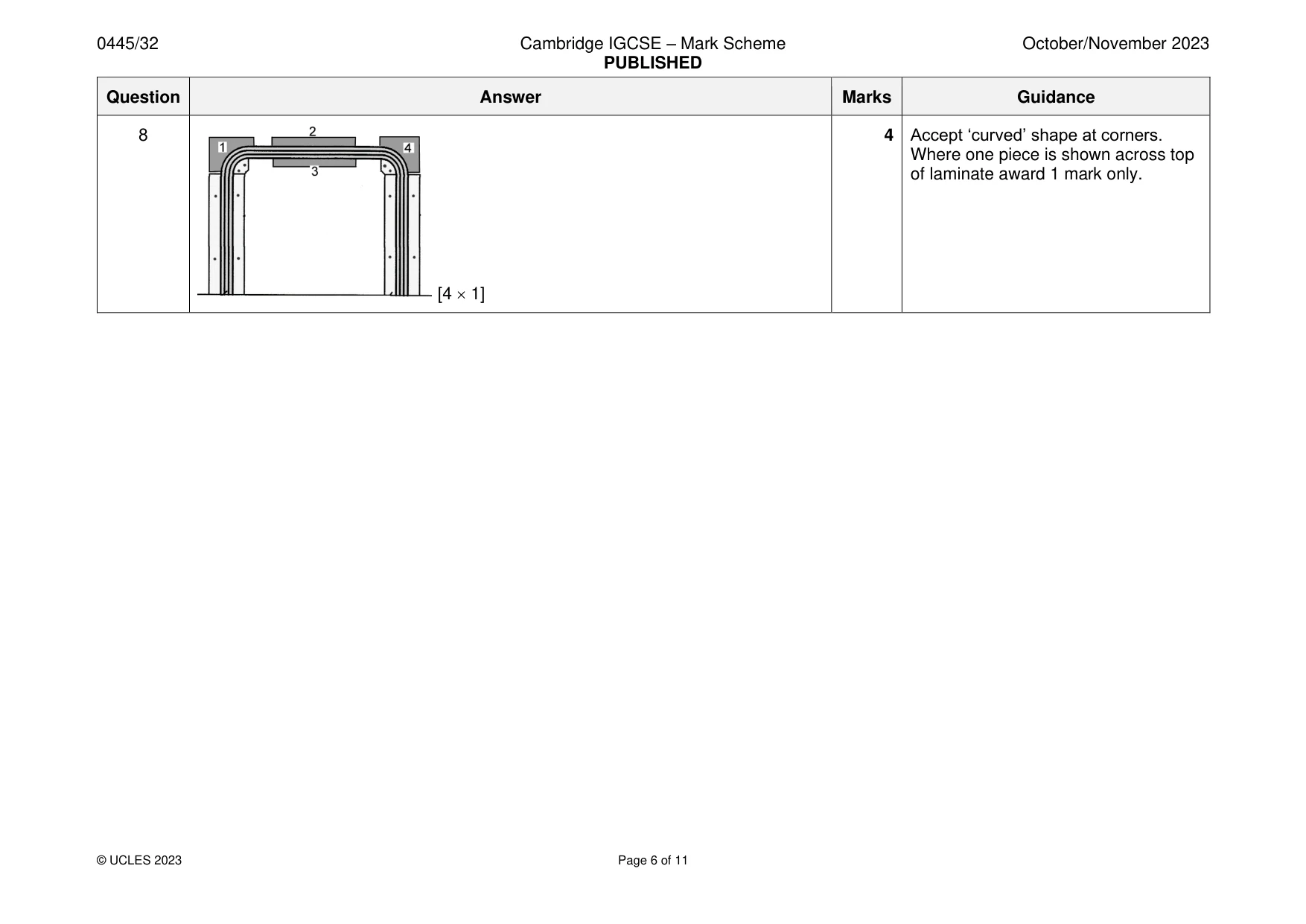
Mark scheme: 8 4 Accept ‘curved’ shape at corners. Where one piece is shown across top of laminate award 1 mark only. [4 1]
Q9 · Select from the list below the metal that corresponds to the description
9 Select from the list below the metal that corresponds to the description. mild steel brass lead cast iron copper (a) Pure metal, good conductor of heat and electricity, easily soldered, corrosion resistant. ............................................................................................................................................. [1] (b) Pure metal, heaviest metal, soft, malleable, excellent chemical resistance. ............................................................................................................................................. [1]
Mark scheme: 9(a) Copper 1 9(b) Lead 1
Q10 · A sectional view through part of a vacuum forming machine and a wooden mould that will be…
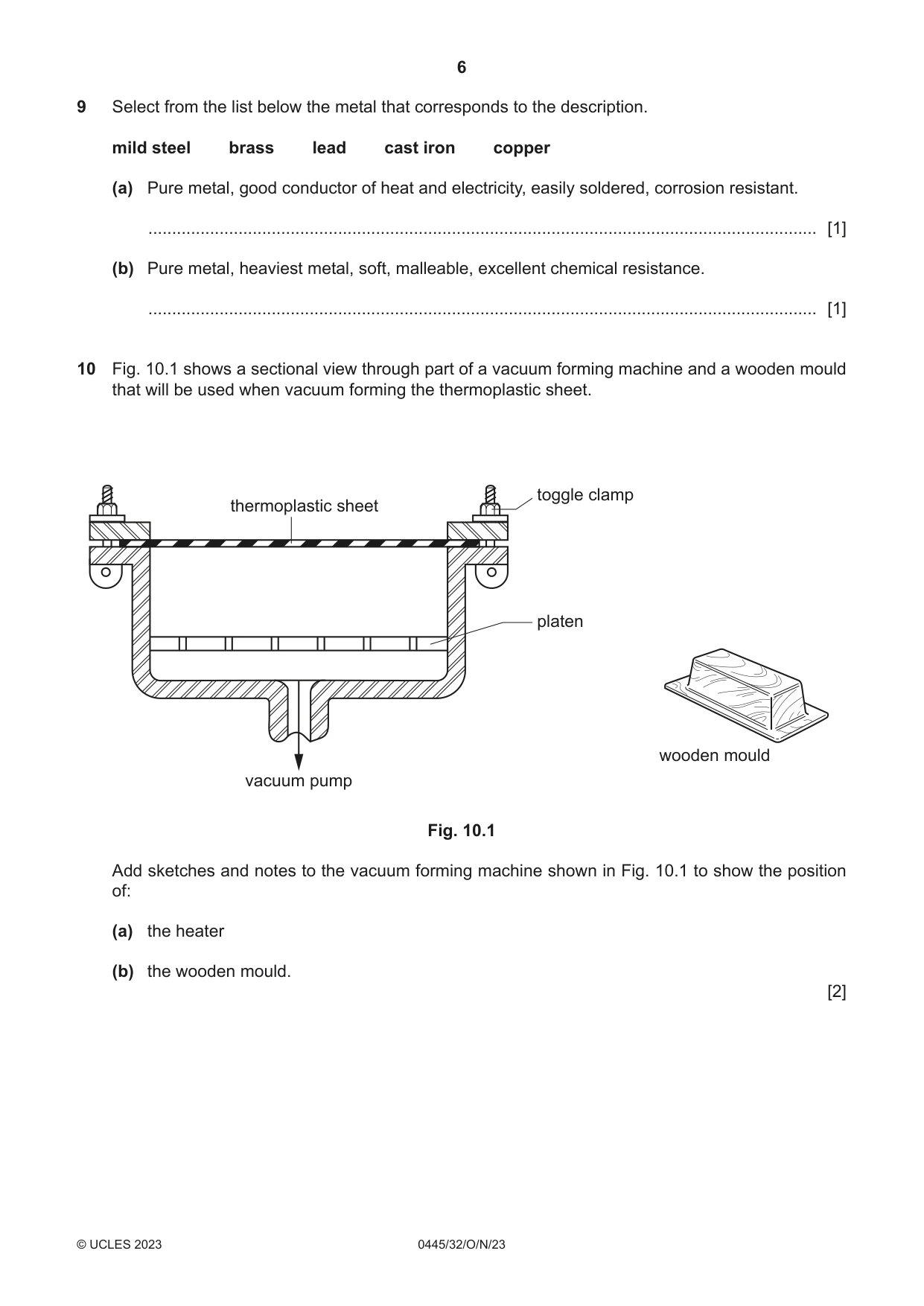
10 Fig. 10.1 shows a sectional view through part of a vacuum forming machine and a wooden mould that will be used when vacuum forming the thermoplastic sheet. toggle clamp thermoplastic sheet platen wooden mould vacuum pump Fig. 10.1 Add sketches and notes to the vacuum forming machine shown in Fig. 10.1 to show the position of: (a) the heater (b) the wooden mould. [2]
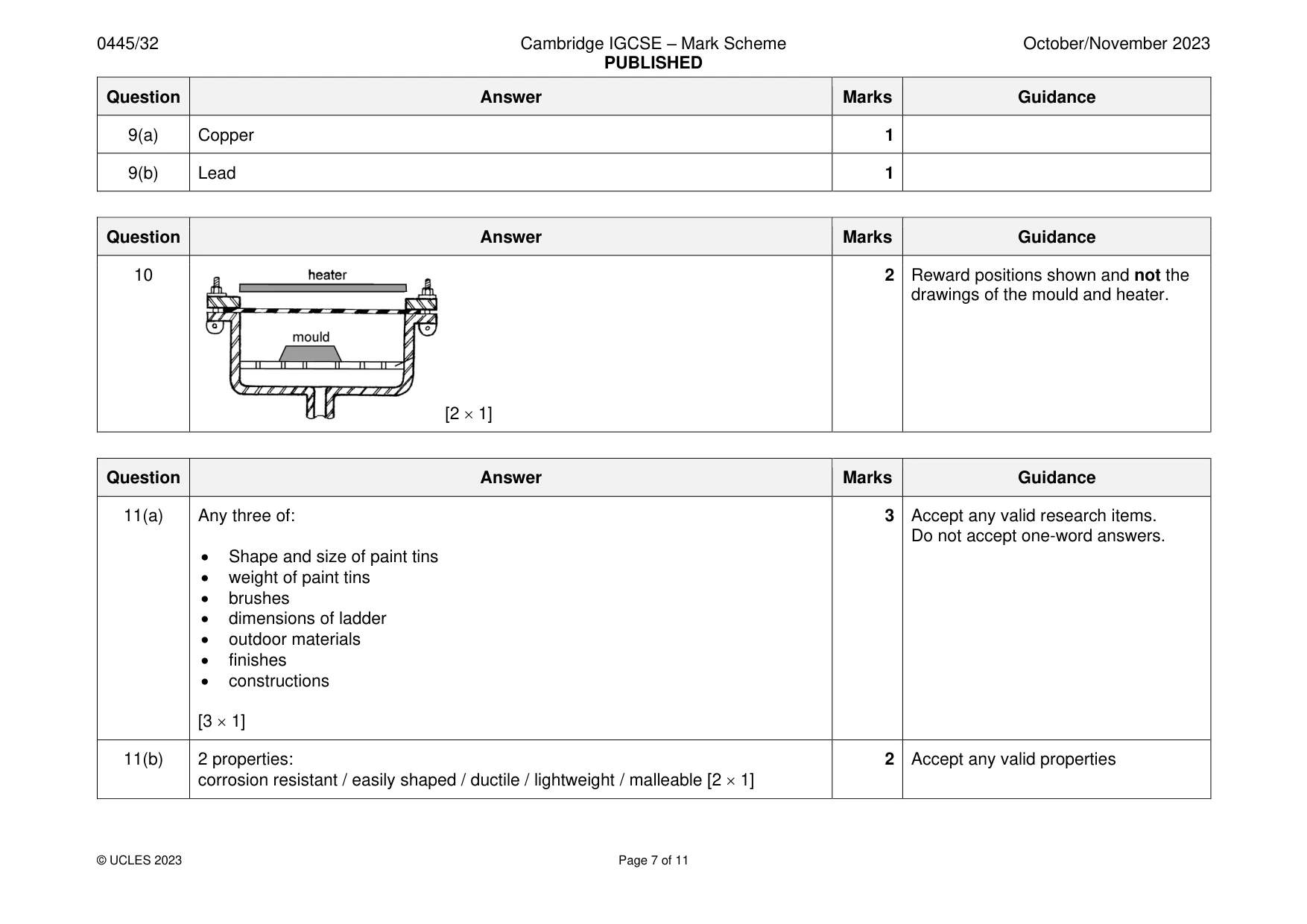
Mark scheme: 10 2 Reward positions shown and not the drawings of the mould and heater. [2 1]
Q11 · An incomplete design for a paint holder that will be used when painting from a ladder
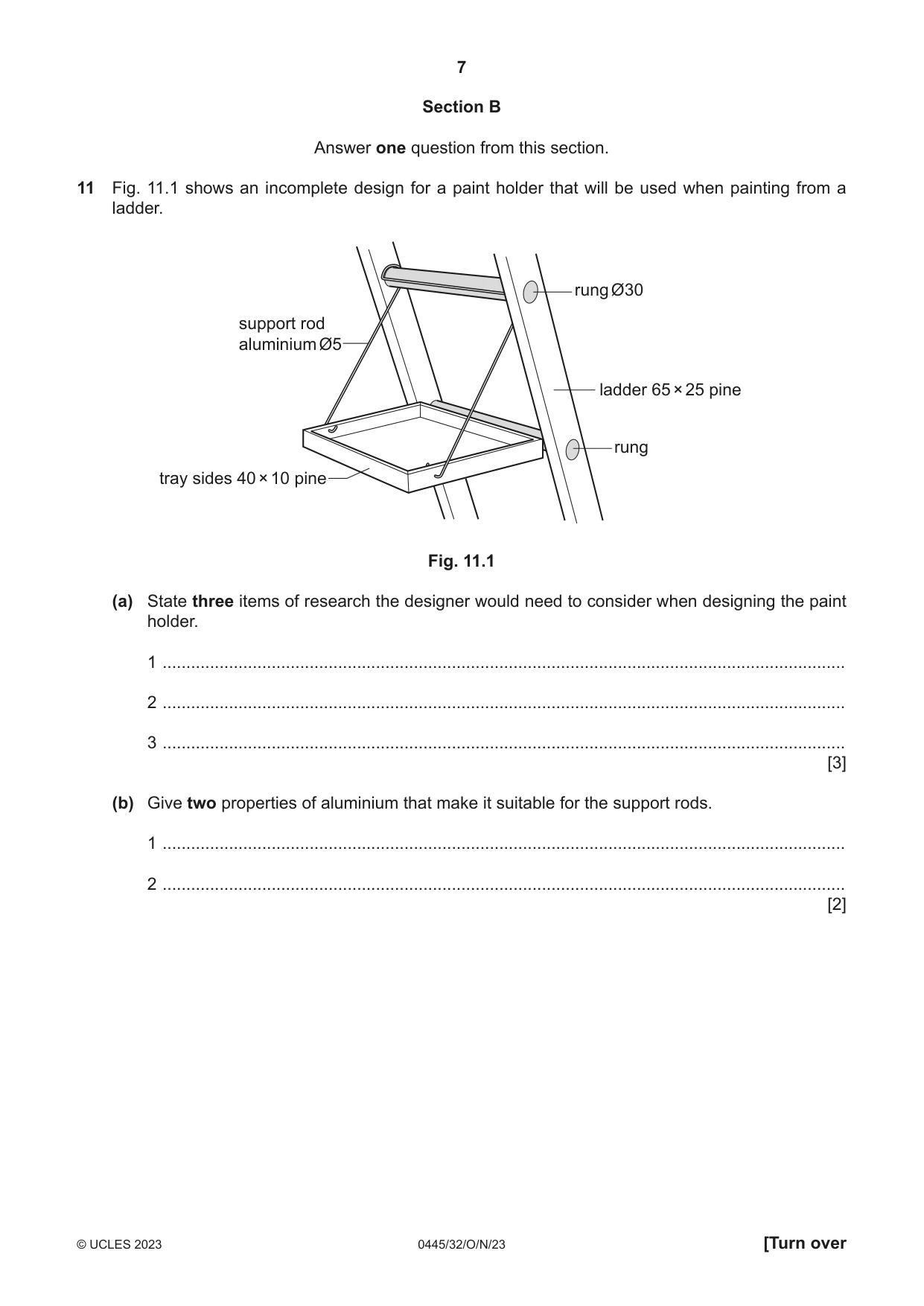
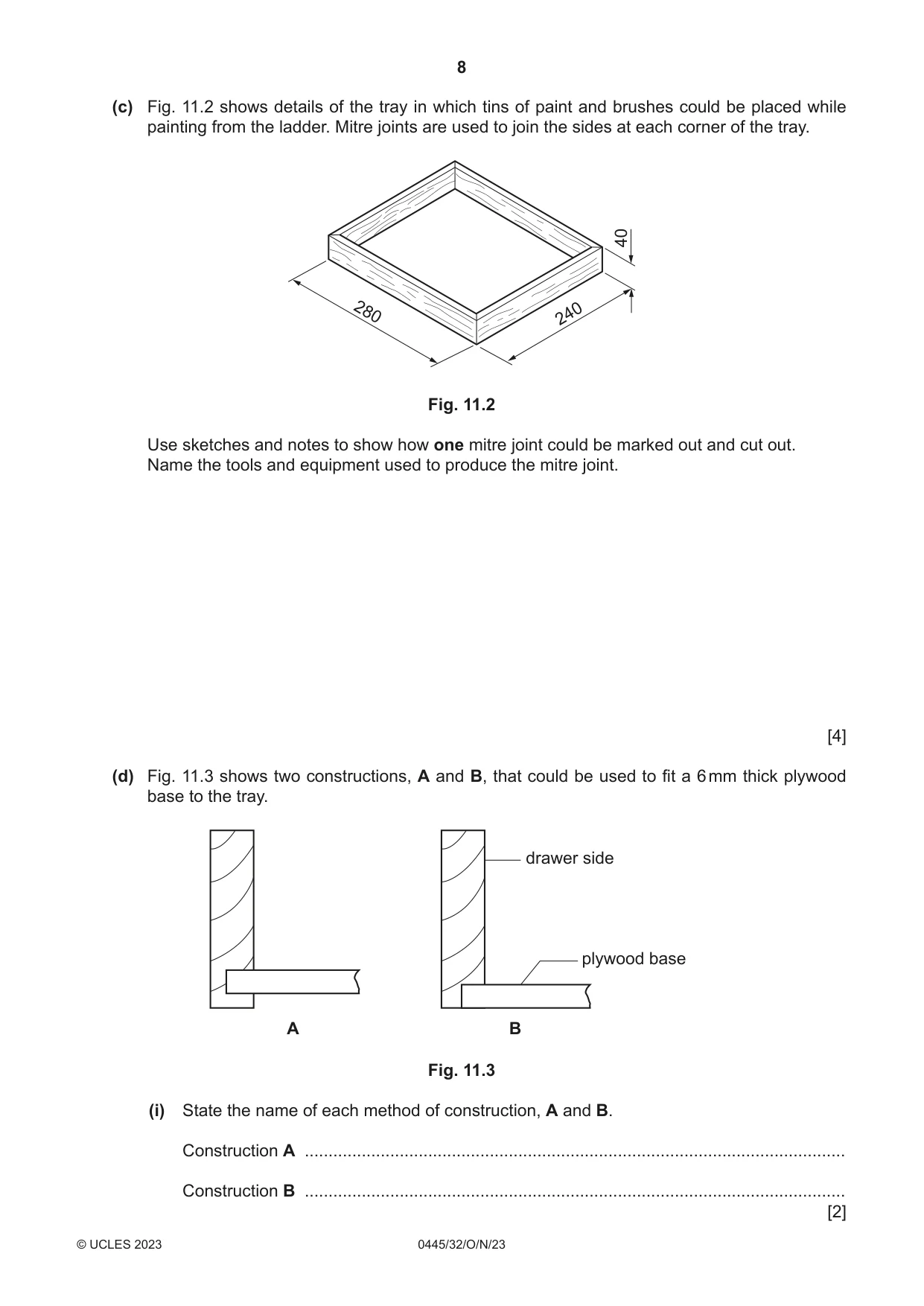
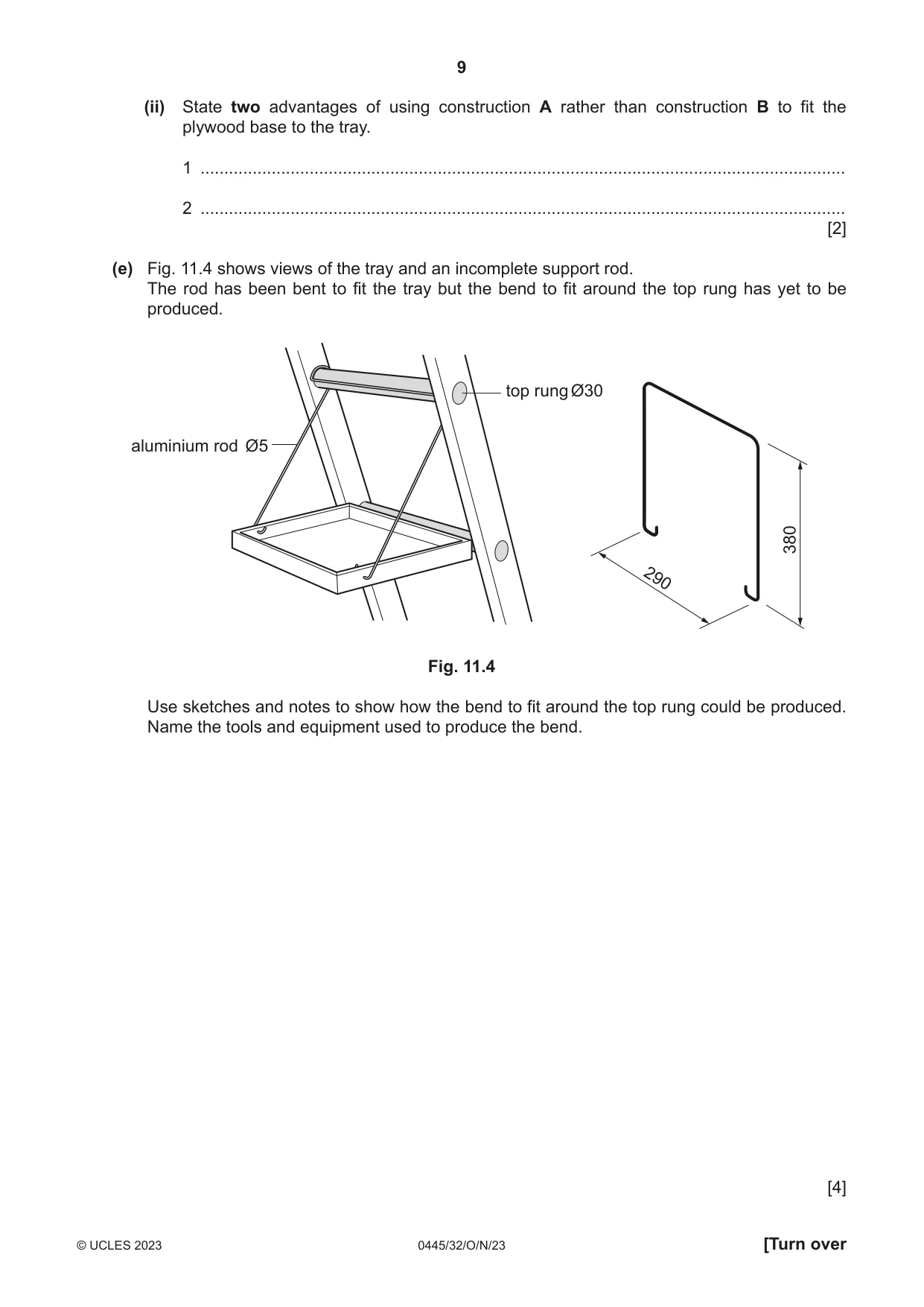
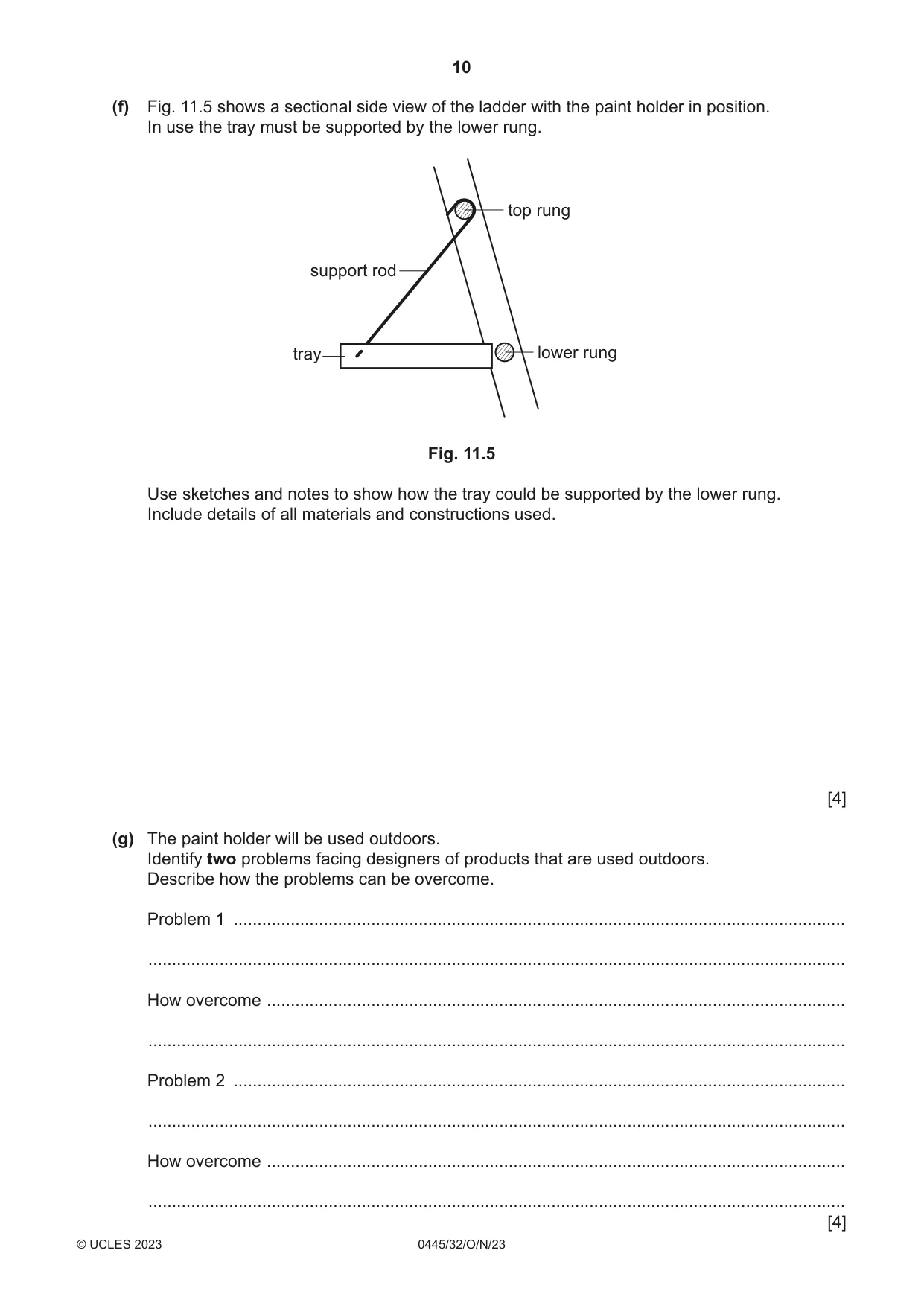
11 Fig. 11.1 shows an incomplete design for a paint holder that will be used when painting from a ladder. rung Ø30 support rod aluminium Ø5 ladder 65 × 25 pine rung tray sides 40 × 10 pine Fig. 11.1 (a) State three items of research the designer would need to consider when designing the paint holder. 1 ................................................................................................................................................ 2 ................................................................................................................................................ 3 ................................................................................................................................................ [3] (b) Give two properties of aluminium that make it suitable for the support rods. 1 ................................................................................................................................................ 2 ................................................................................................................................................ [2] (c) Fig. 11.2 shows details of the tray in which tins of paint and brushes could be placed while painting from the ladder. Mitre joints are used to join the sides at each corner of the tray. 40 280 240 Fig. 11.2 Use sketches and notes to show how one mitre joint could be marked out and cut out. Name the tools and equipment used to produce the mitre joint. [4] (d) Fig. 11.3 shows two constructions, A and B, that could be used to fit a 6 mm thick plywood base to the tray. drawer side plywood base A B Fig. 11.3 (i) State the name of each method of construction, A and B. Construction A .................................................................................................................. Construction B .................................................................................................................. [2] (ii) State two advantages of using construction A rather than construction B to fit the plywood base to the tray. 1 ........................................................................................................................................ 2 ........................................................................................................................................ [2] (e) Fig. 11.4 shows views of the tray and an incomplete support rod. The rod has been bent to fit the tray but the bend to fit around the top rung has yet to be produced. top rung Ø30 aluminium rod Ø5 380 290 Fig. 11.4 Use sketches and notes to show how the bend to fit around the top rung could be produced. Name the tools and equipment used to produce the bend. [4] (f) Fig. 11.5 shows a sectional side view of the ladder with the paint holder in position. In use the tray must be supported by the lower rung. top rung support rod tray lower rung Fig. 11.5 Use sketches and notes to show how the tray could be supported by the lower rung. Include details of all materials and constructions used. [4] (g) The paint holder will be used outdoors. Identify two problems facing designers of products that are used outdoors. Describe how the problems can be overcome. Problem 1 ................................................................................................................................. ................................................................................................................................................... How overcome .......................................................................................................................... ................................................................................................................................................... Problem 2 ................................................................................................................................. ................................................................................................................................................... How overcome .......................................................................................................................... ................................................................................................................................................... [4]
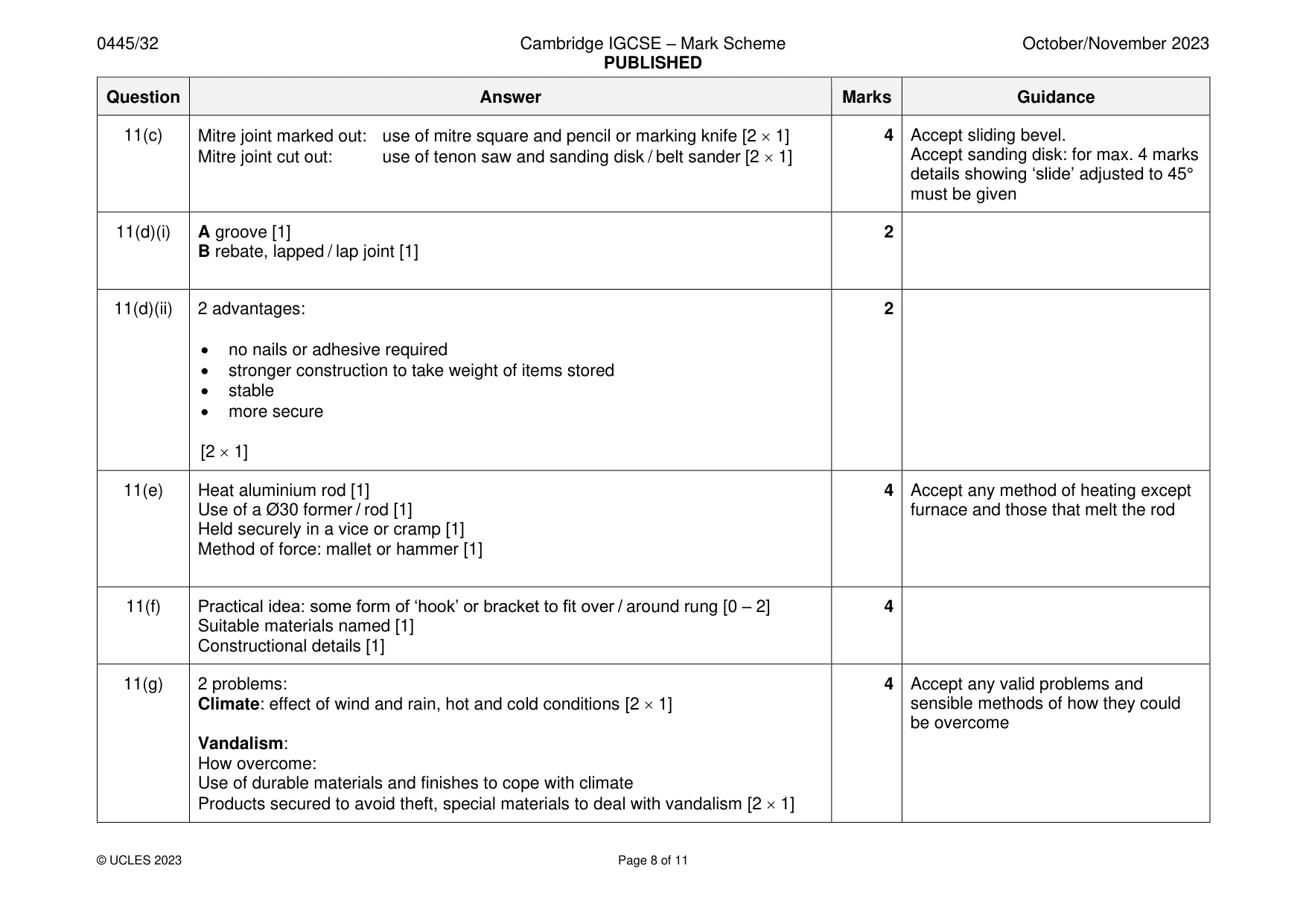
Mark scheme: 11(a) Any three of: 3 Accept any valid research items. Do not accept one-word answers. • Shape and size of paint tins • weight of paint tins • brushes • dimensions of ladder • outdoor materials • finishes • constructions [3 1] 11(b) 2 properties: 2 Accept any valid properties corrosion resistant / easily shaped / ductile / lightweight / malleable [2 1] 11(c) Mitre joint marked out: use of mitre square and pencil or marking knife [2 1] 4 Accept sliding bevel. Mitre joint cut out: use of tenon saw and sanding disk / belt sander [2 1] Accept sanding disk: for max. 4 marks details showing ‘slide’ adjusted to 45° must be given 11(d)(i) A groove [1] 2 B rebate, lapped / lap joint [1] 11(d)(ii) 2 advantages: 2 • no nails or adhesive required • stronger construction to take weight of items stored • stable • more secure [2 1] 11(e) Heat aluminium rod [1] 4 Accept any method of heating except Use of a Ø30 former / rod [1] furnace and those that melt the rod Held securely in a vice or cramp [1] Method of force: mallet or hammer [1] 11(f) Practical idea: some form of ‘hook’ or bracket to fit over / around rung [0 – 2] 4 Suitable materials named [1] Constructional details [1] 11(g) 2 problems: 4 Accept any valid problems and Climate: effect of wind and rain, hot and cold conditions [2 1] sensible methods of how they could be overcome Vandalism: How overcome: Use of durable materials and finishes to cope with climate Products secured to avoid theft, special materials to deal with vandalism [2 1]
Q12 · A Design and Technology student has been asked by a local nursery to design a chair…
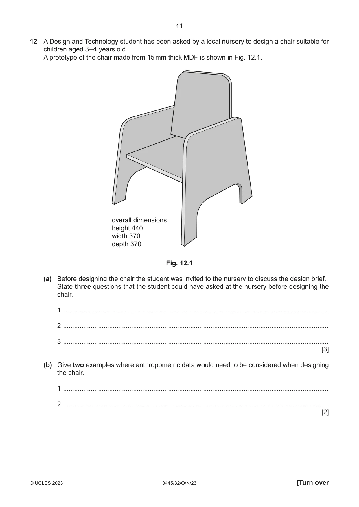
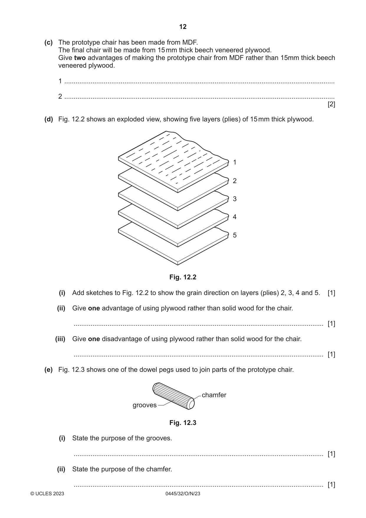
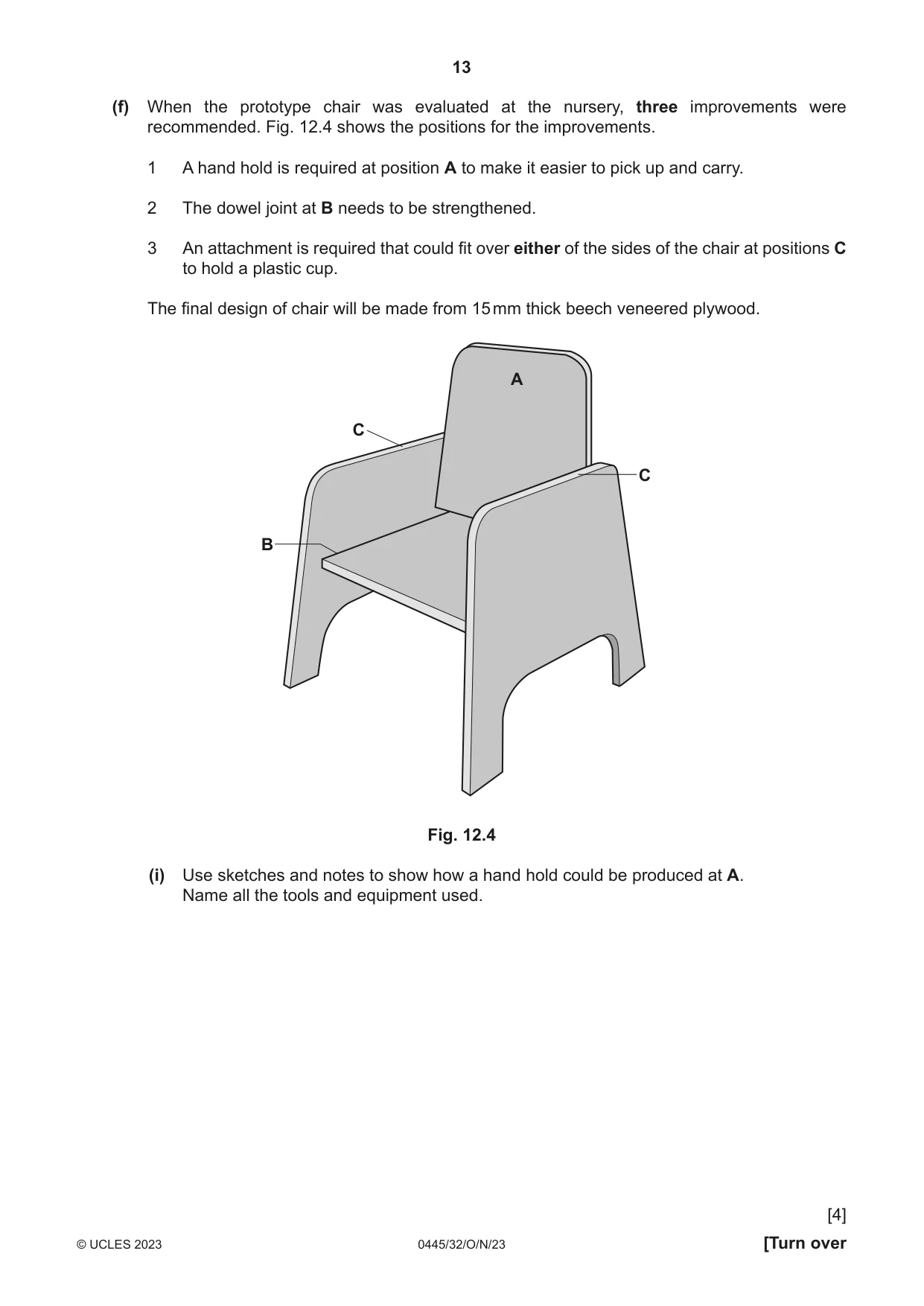
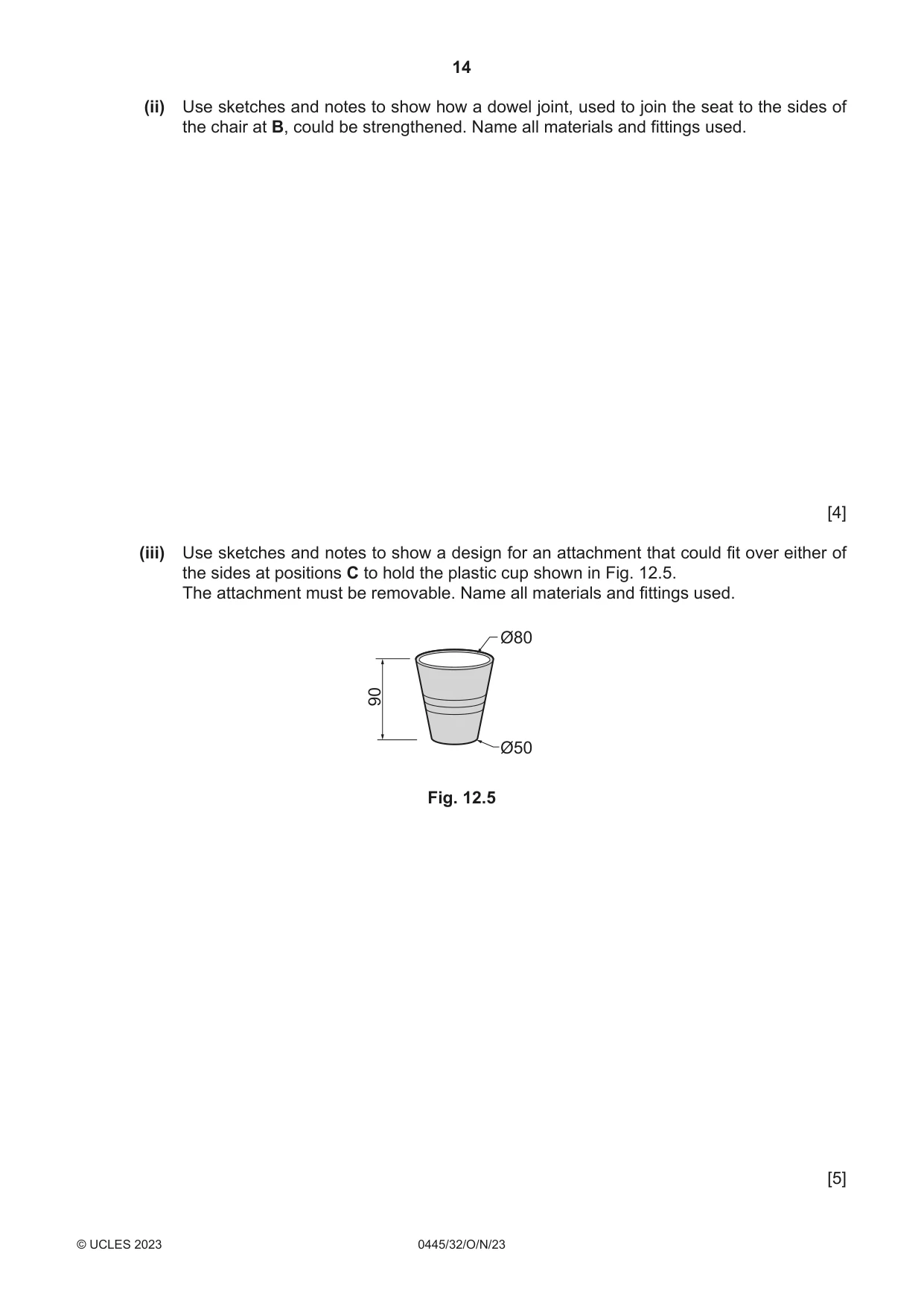
12 A Design and Technology student has been asked by a local nursery to design a chair suitable for children aged 3–4 years old. A prototype of the chair made from 15 mm thick MDF is shown in Fig. 12.1. overall dimensions height 440 width 370 depth 370 Fig. 12.1 (a) Before designing the chair the student was invited to the nursery to discuss the design brief. State three questions that the student could have asked at the nursery before designing the chair. 1 ................................................................................................................................................ 2 ................................................................................................................................................ 3 ................................................................................................................................................ [3] (b) Give two examples where anthropometric data would need to be considered when designing the chair. 1 ................................................................................................................................................ 2 ................................................................................................................................................ [2] (c) The prototype chair has been made from MDF. The final chair will be made from 15 mm thick beech veneered plywood. Give two advantages of making the prototype chair from MDF rather than 15mm thick beech veneered plywood. 1 ................................................................................................................................................ 2 ................................................................................................................................................ [2] (d) Fig. 12.2 shows an exploded view, showing five layers (plies) of 15 mm thick plywood. 1 2 3 4 5 Fig. 12.2 (i) Add sketches to Fig. 12.2 to show the grain direction on layers (plies) 2, 3, 4 and 5. [1] (ii) Give one advantage of using plywood rather than solid wood for the chair. ..................................................................................................................................... [1] (iii) Give one disadvantage of using plywood rather than solid wood for the chair. ..................................................................................................................................... [1] (e) Fig. 12.3 shows one of the dowel pegs used to join parts of the prototype chair. chamfer grooves Fig. 12.3 (i) State the purpose of the grooves. ..................................................................................................................................... [1] (ii) State the purpose of the chamfer. ..................................................................................................................................... [1] (f) When the prototype chair was evaluated at the nursery, three improvements were recommended. Fig. 12.4 shows the positions for the improvements. 1 A hand hold is required at position A to make it easier to pick up and carry. 2 The dowel joint at B needs to be strengthened. 3 An attachment is required that could fit over either of the sides of the chair at positions C to hold a plastic cup. The final design of chair will be made from 15 mm thick beech veneered plywood. A C C B Fig. 12.4 (i) Use sketches and notes to show how a hand hold could be produced at A. Name all the tools and equipment used. [4] (ii) Use sketches and notes to show how a dowel joint, used to join the seat to the sides of the chair at B, could be strengthened. Name all materials and fittings used. [4] (iii) Use sketches and notes to show a design for an attachment that could fit over either of the sides at positions C to hold the plastic cup shown in Fig. 12.5. The attachment must be removable. Name all materials and fittings used. Ø80 90 Ø50 Fig. 12.5 [5]
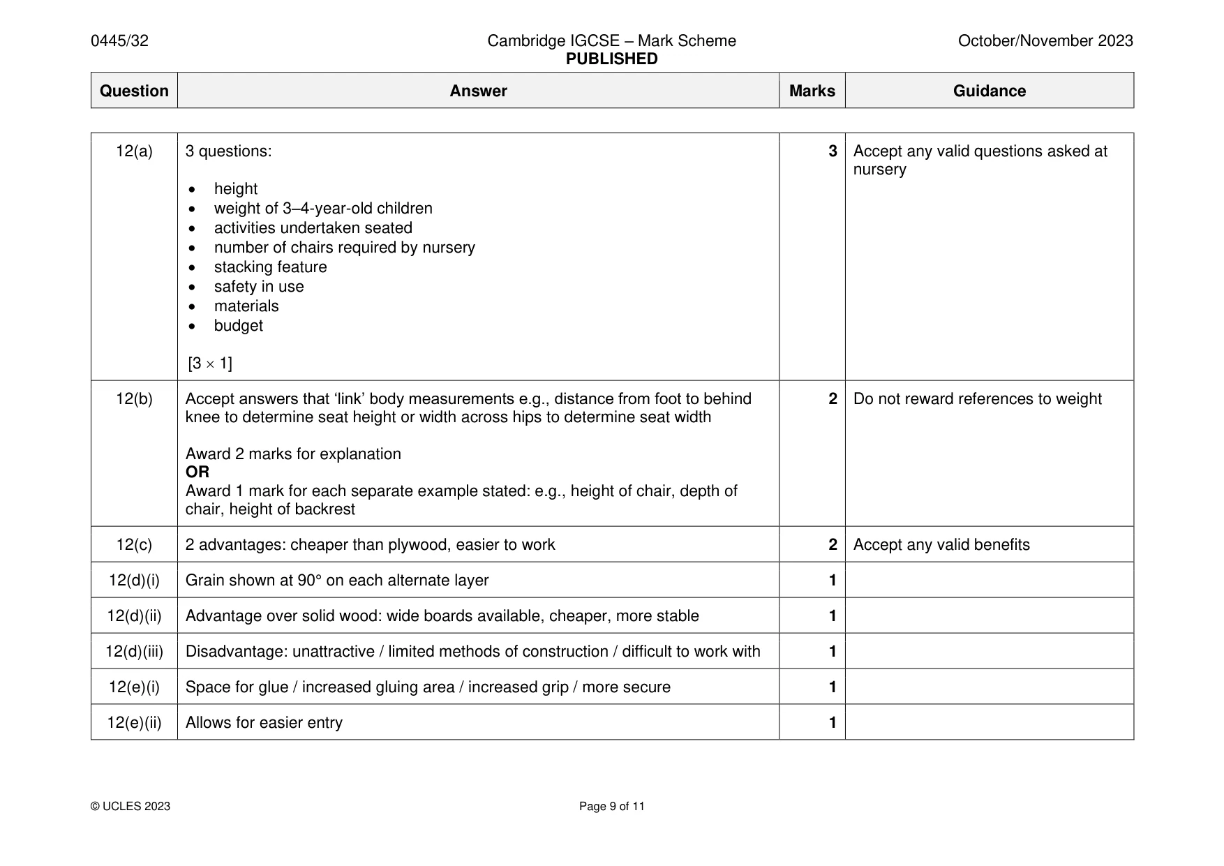
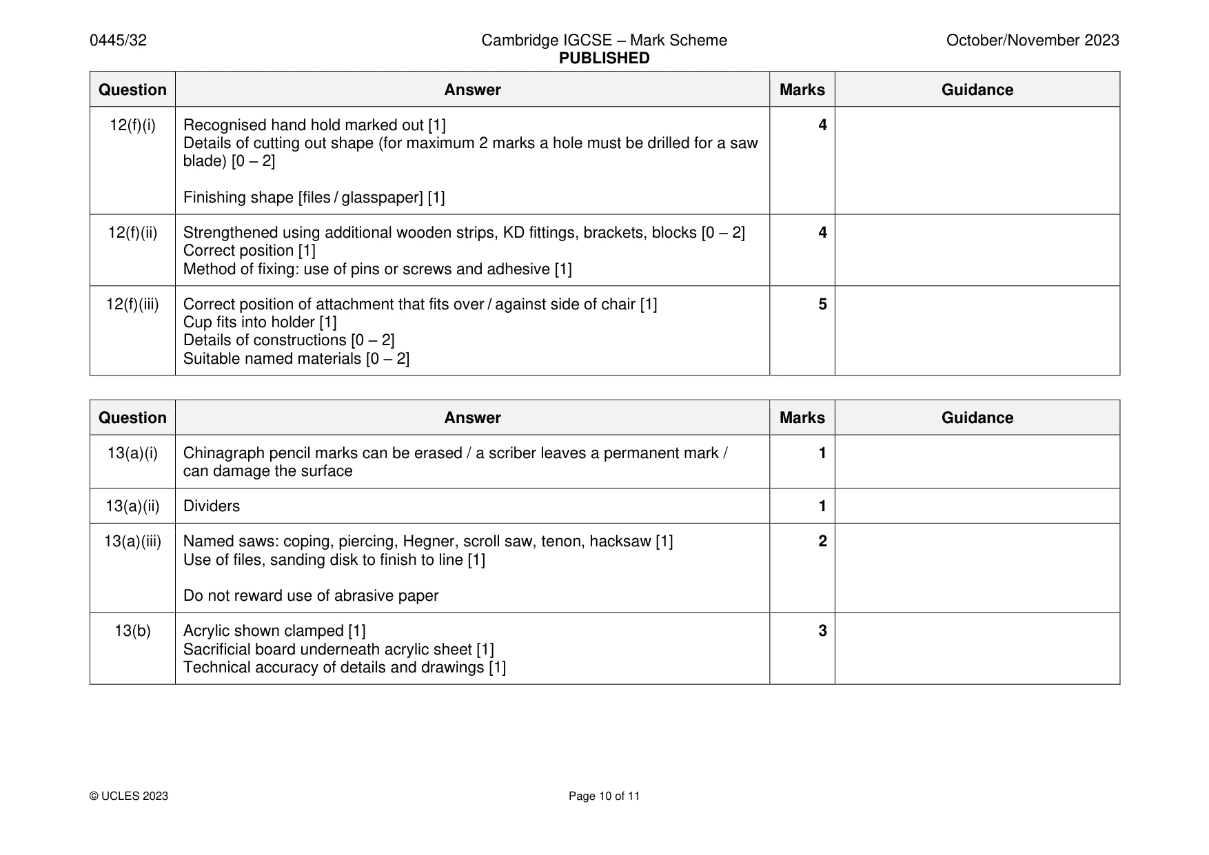
Mark scheme: 12(a) 3 questions: 3 Accept any valid questions asked at nursery • height • weight of 3–4-year-old children • activities undertaken seated • number of chairs required by nursery • stacking feature • safety in use • materials • budget [3 1] 12(b) Accept answers that ‘link’ body measurements e.g., distance from foot to behind 2 Do not reward references to weight knee to determine seat height or width across hips to determine seat width Award 2 marks for explanation OR Award 1 mark for each separate example stated: e.g., height of chair, depth of chair, height of backrest 12(c) 2 advantages: cheaper than plywood, easier to work 2 Accept any valid benefits 12(d)(i) Grain shown at 90° on each alternate layer 1 12(d)(ii) Advantage over solid wood: wide boards available, cheaper, more stable 1 12(d)(iii) Disadvantage: unattractive / limited methods of construction / difficult to work with 1 12(e)(i) Space for glue / increased gluing area / increased grip / more secure 1 12(e)(ii) Allows for easier entry 1 12(f)(i) Recognised hand hold marked out [1] 4 Details of cutting out shape (for maximum 2 marks a hole must be drilled for a saw blade) [0 – 2] Finishing shape [files / glasspaper] [1] 12(f)(ii) Strengthened using additional wooden strips, KD fittings, brackets, blocks [0 – 2] 4 Correct position [1] Method of fixing: use of pins or screws and adhesive [1] 12(f)(iii) Correct position of attachment that fits over / against side of chair [1] 5 Cup fits into holder [1] Details of constructions [0 – 2] Suitable named materials [0 – 2]
Q13 · Views of an adjustable table lamp made of acrylic
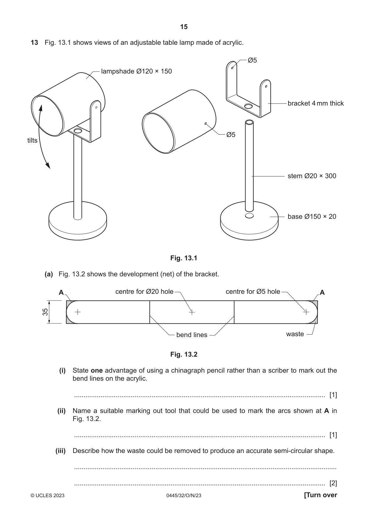
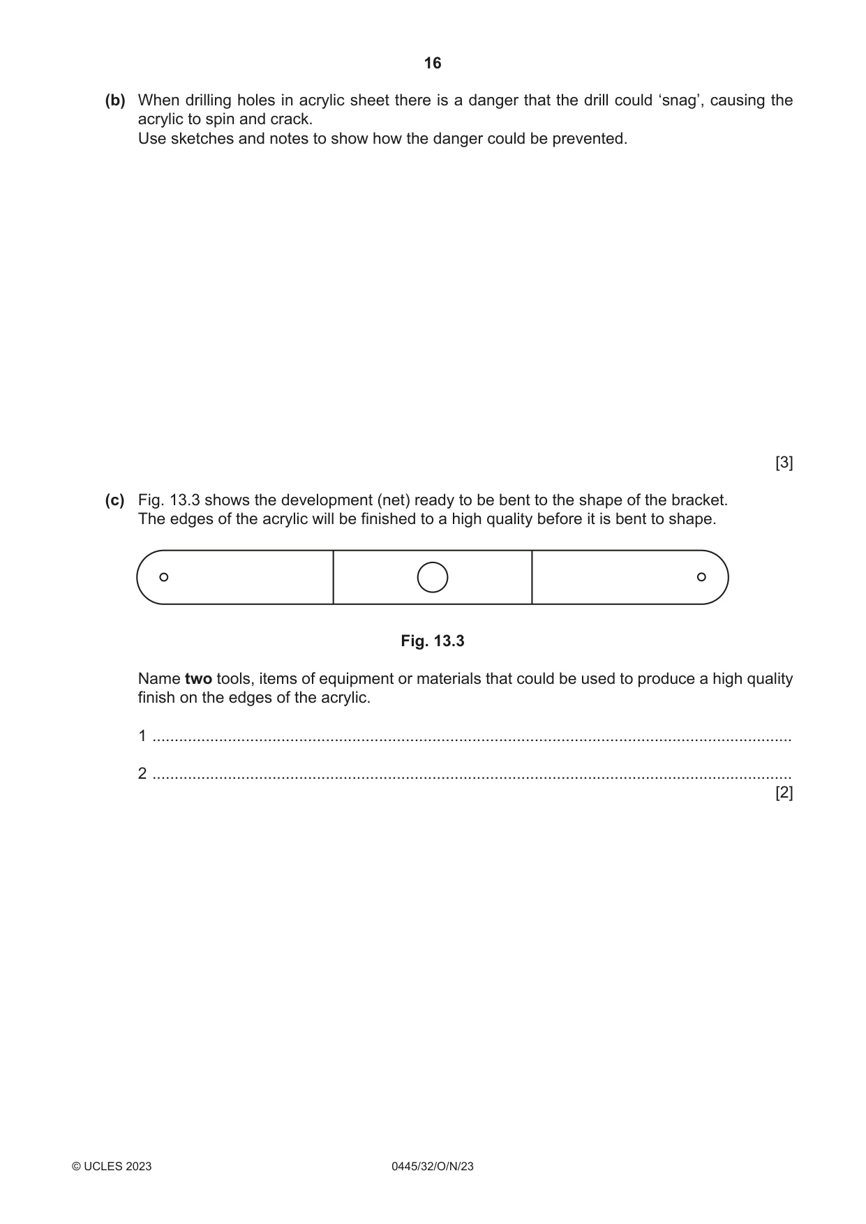
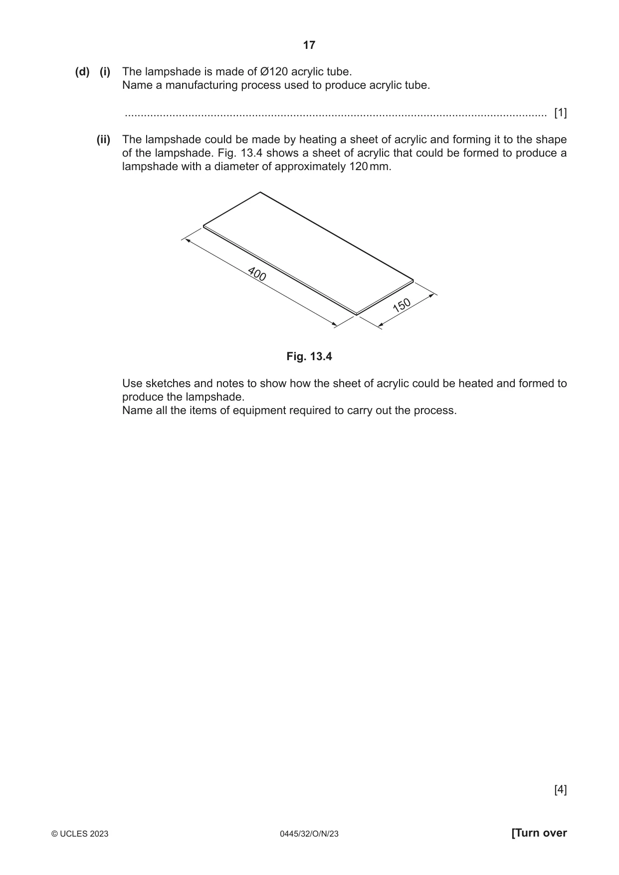
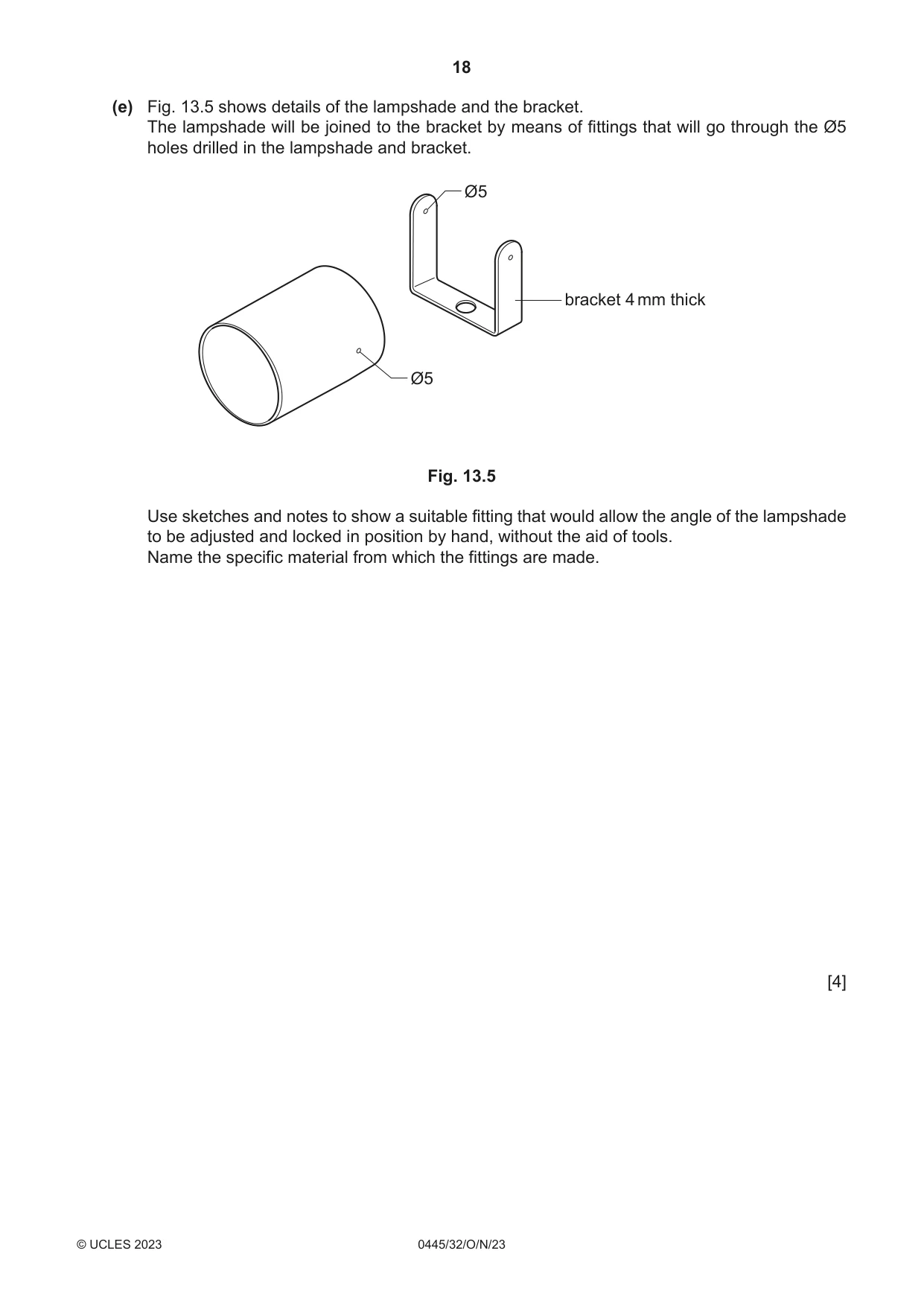
13 Fig. 13.1 shows views of an adjustable table lamp made of acrylic. Ø5 lampshade Ø120 × 150 bracket 4 mm thick Ø5 tilts stem Ø20 × 300 base Ø150 × 20 Fig. 13.1 (a) Fig. 13.2 shows the development (net) of the bracket. A centre for Ø20 hole centre for Ø5 hole A 35 bend lines waste Fig. 13.2 (i) State one advantage of using a chinagraph pencil rather than a scriber to mark out the bend lines on the acrylic. ..................................................................................................................................... [1] (ii) Name a suitable marking out tool that could be used to mark the arcs shown at A in Fig. 13.2. ..................................................................................................................................... [1] (iii) Describe how the waste could be removed to produce an accurate semi-circular shape. ........................................................................................................................................... ..................................................................................................................................... [2] (b) When drilling holes in acrylic sheet there is a danger that the drill could ‘snag’, causing the acrylic to spin and crack. Use sketches and notes to show how the danger could be prevented. [3] (c) Fig. 13.3 shows the development (net) ready to be bent to the shape of the bracket. The edges of the acrylic will be finished to a high quality before it is bent to shape. Fig. 13.3 Name two tools, items of equipment or materials that could be used to produce a high quality finish on the edges of the acrylic. 1 ................................................................................................................................................ 2 ................................................................................................................................................ [2] (d) (i) The lampshade is made of Ø120 acrylic tube. Name a manufacturing process used to produce acrylic tube. ..................................................................................................................................... [1] (ii) The lampshade could be made by heating a sheet of acrylic and forming it to the shape of the lampshade. Fig. 13.4 shows a sheet of acrylic that could be formed to produce a lampshade with a diameter of approximately 120 mm. 400 150 Fig. 13.4 Use sketches and notes to show how the sheet of acrylic could be heated and formed to produce the lampshade. Name all the items of equipment required to carry out the process. [4]
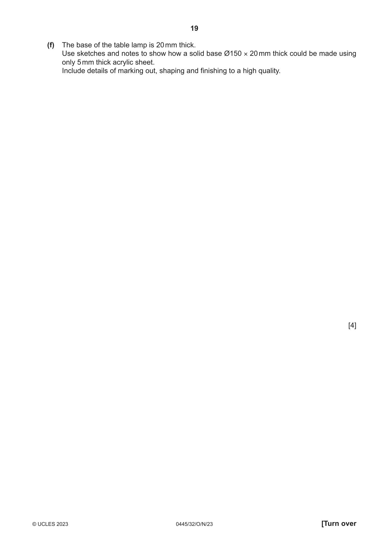
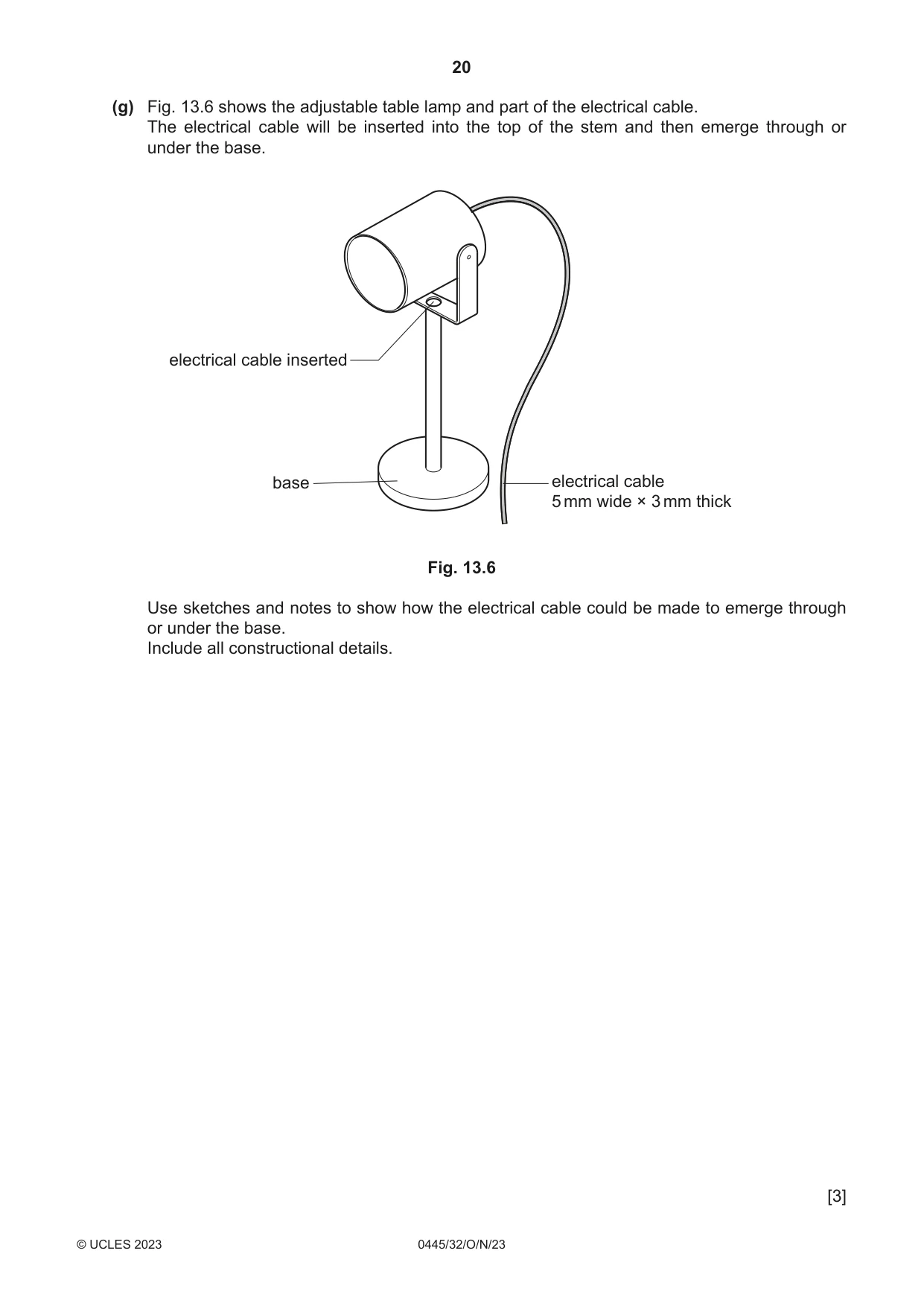
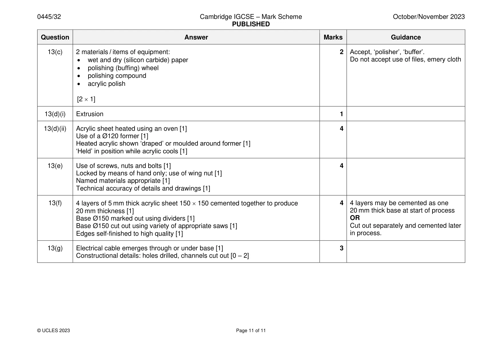
Mark scheme: 13(a)(i) Chinagraph pencil marks can be erased / a scriber leaves a permanent mark / 1 can damage the surface 13(a)(ii) Dividers 1 13(a)(iii) Named saws: coping, piercing, Hegner, scroll saw, tenon, hacksaw [1] 2 Use of files, sanding disk to finish to line [1] Do not reward use of abrasive paper 13(b) Acrylic shown clamped [1] 3 Sacrificial board underneath acrylic sheet [1] Technical accuracy of details and drawings [1] 13(c) 2 materials / items of equipment: 2 Accept, ‘polisher’, ‘buffer’. • wet and dry (silicon carbide) paper Do not accept use of files, emery cloth • polishing (buffing) wheel • polishing compound • acrylic polish [2 1] 13(d)(i) Extrusion 1 13(d)(ii) Acrylic sheet heated using an oven [1] 4 Use of a Ø120 former [1] Heated acrylic shown ‘draped’ or moulded around former [1] ‘Held’ in position while acrylic cools [1] 13(e) Use of screws, nuts and bolts [1] 4 Locked by means of hand only; use of wing nut [1] Named materials appropriate [1] Technical accuracy of details and drawings [1] 13(f) 4 layers of 5 mm thick acrylic sheet 150 150 cemented together to produce 4 4 layers may be cemented as one 20 mm thickness [1] 20 mm thick base at start of process Base Ø150 marked out using dividers [1] OR Base Ø150 cut out using variety of appropriate saws [1] Cut out separately and cemented later Edges self-finished to high quality [1] in process. 13(g) Electrical cable emerges through or under base [1] 3 Constructional details: holes drilled, channels cut out [0 – 2]
What was in this paper
The subtopics covered by these 13 questions, and how many questions each got. Open one in a new tab to see every Cambridge question on it.
What you needed in this session
Cambridge’s own grade thresholds for 2023 Oct/Nov, Paper 3 · Variant 2. A higher threshold means an easier paper — the bar moves with how the cohort did.