Cambridge IGCSE Design and Technology 0445 — 2025 May/June Paper 3 · Variant 2
0445/32/M/J/25 · 13 questions · 50 marks · 60 min
The question paper and its mark scheme, free to read here and free to download. This is Cambridge’s own paper, exactly as it was sat.
Question paper20 pages
Mark scheme12 pages
Answers below. Sit the paper first if you are practising.
Questions as text
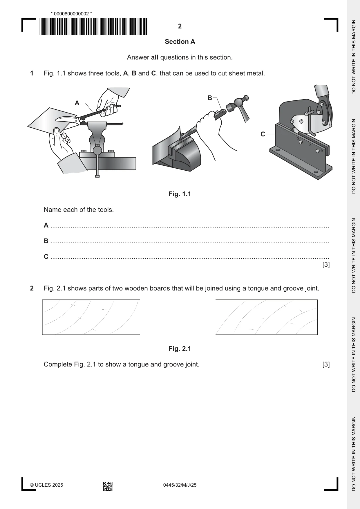
Q1 · Three tools, A, B and C, that can be used to cut sheet metal
1 Fig. 1.1 shows three tools, A, B and C, that can be used to cut sheet metal. B A C Fig. 1.1 Name each of the tools. A ....................................................................................................................................................... B ....................................................................................................................................................... C ....................................................................................................................................................... [3]
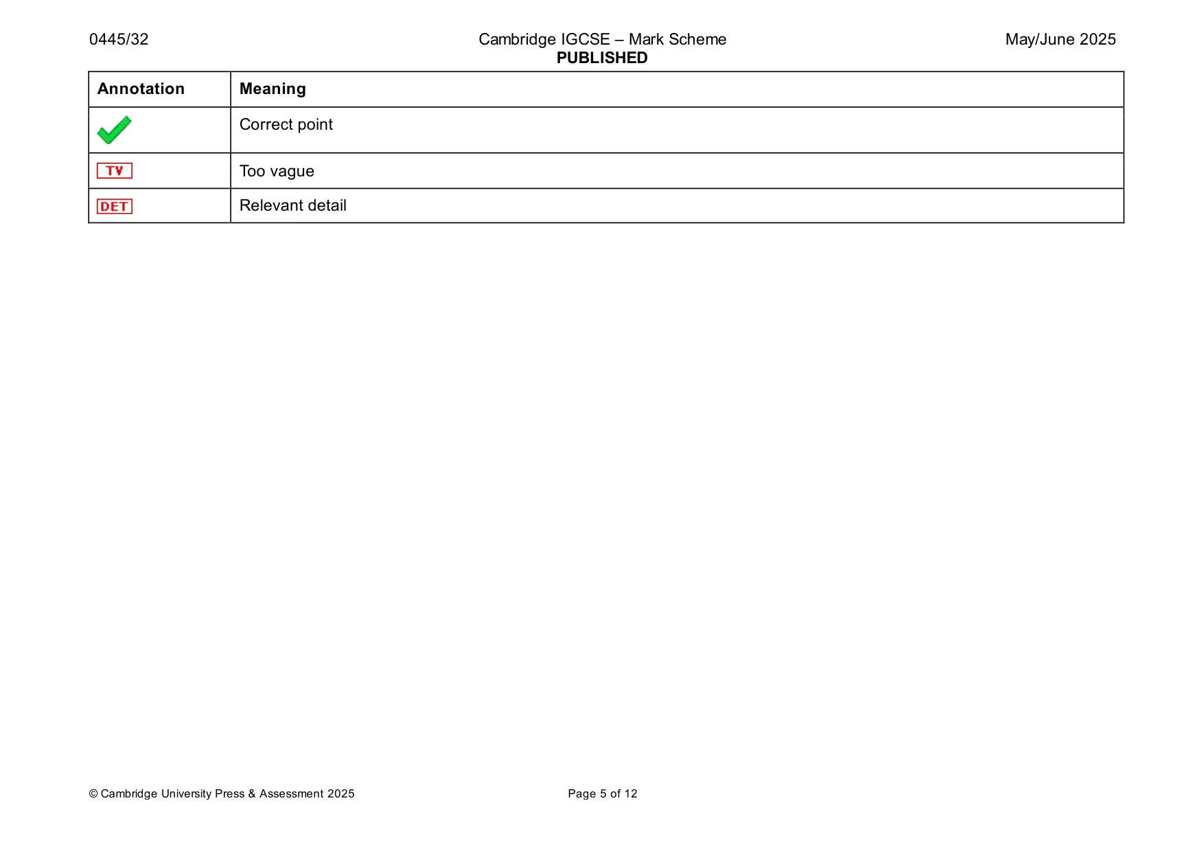
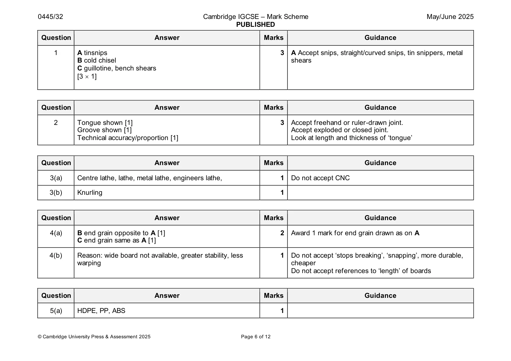
Mark scheme: Question Answer Marks Guidance 1 A tinsnips 3 A Accept snips, straight/curved snips, tin snippers, metal B cold chisel shears C guillotine, bench shears [3 1]
Q2 · Parts of two wooden boards that will be joined using a tongue and groove joint
2 Fig. 2.1 shows parts of two wooden boards that will be joined using a tongue and groove joint. Fig. 2.1 Complete Fig. 2.1 to show a tongue and groove joint. [3]
Mark scheme: 2 Tongue shown [1] 3 Accept freehand or ruler-drawn joint. Groove shown [1] Accept exploded or closed joint. Technical accuracy/proportion [1] Look at length and thickness of ‘tongue’
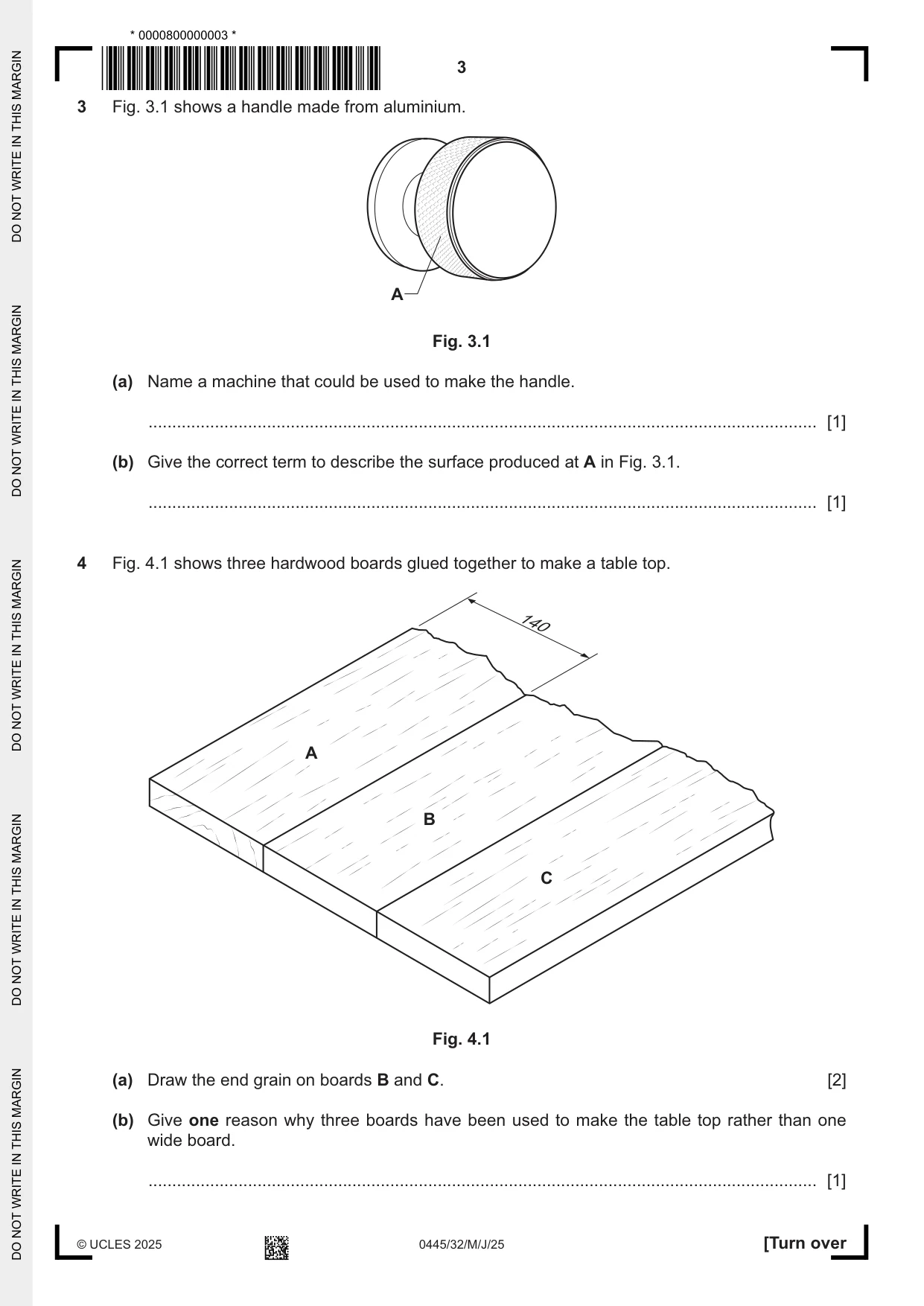
Q3 · A handle made from aluminium
3 Fig. 3.1 shows a handle made from aluminium. A Fig. 3.1 (a) Name a machine that could be used to make the handle. ............................................................................................................................................. [1] (b) Give the correct term to describe the surface produced at A in Fig. 3.1. ............................................................................................................................................. [1]
Mark scheme: 3(a) Centre lathe, lathe, metal lathe, engineers lathe, 1 Do not accept CNC 3(b) Knurling 1
Q4 · Three hardwood boards glued together to make a table top
4 Fig. 4.1 shows three hardwood boards glued together to make a table top. 140 A B C Fig. 4.1 (a) Draw the end grain on boards B and C. [2] (b) Give one reason why three boards have been used to make the table top rather than one wide board. ............................................................................................................................................. [1]
Mark scheme: 4(a) B end grain opposite to A [1] 2 Award 1 mark for end grain drawn as on A C end grain same as A [1] 4(b) Reason: wide board not available, greater stability, less 1 Do not accept ‘stops breaking’, ‘snapping’, more durable, warping cheaper Do not accept references to ‘length’ of boards
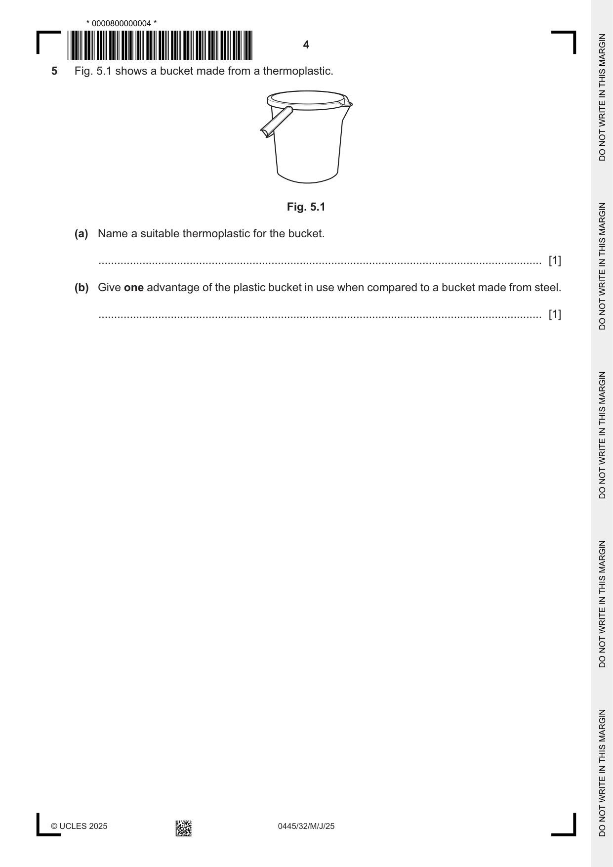
Q5 · A bucket made from a thermoplastic
5 Fig. 5.1 shows a bucket made from a thermoplastic. Fig. 5.1 (a) Name a suitable thermoplastic for the bucket. ............................................................................................................................................. [1] (b) Give one advantage of the plastic bucket in use when compared to a bucket made from steel. ............................................................................................................................................. [1]
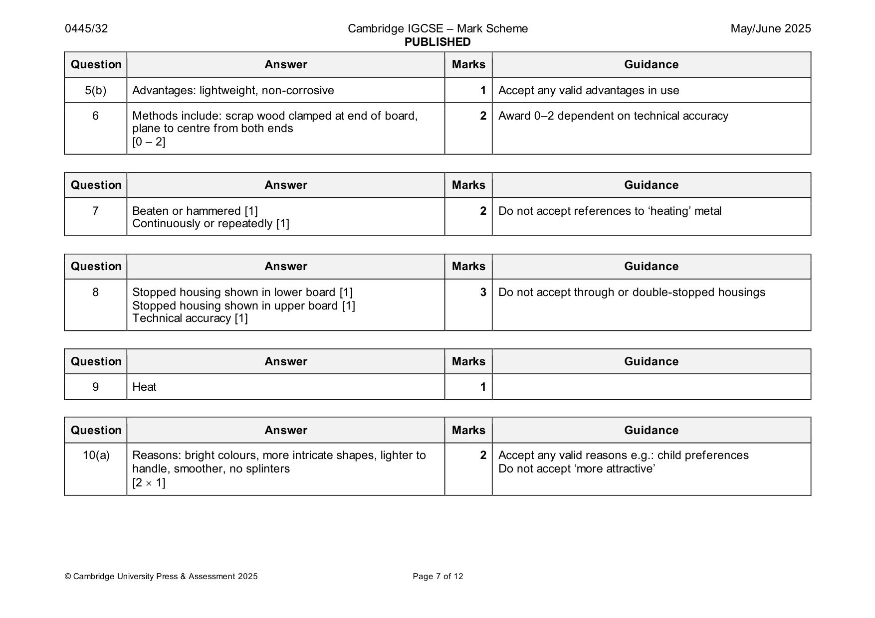
Mark scheme: 5(a) HDPE, PP, ABS 1 5(b) Advantages: lightweight, non-corrosive 1 Accept any valid advantages in use
Q6 · The end grain of hardwood being planed
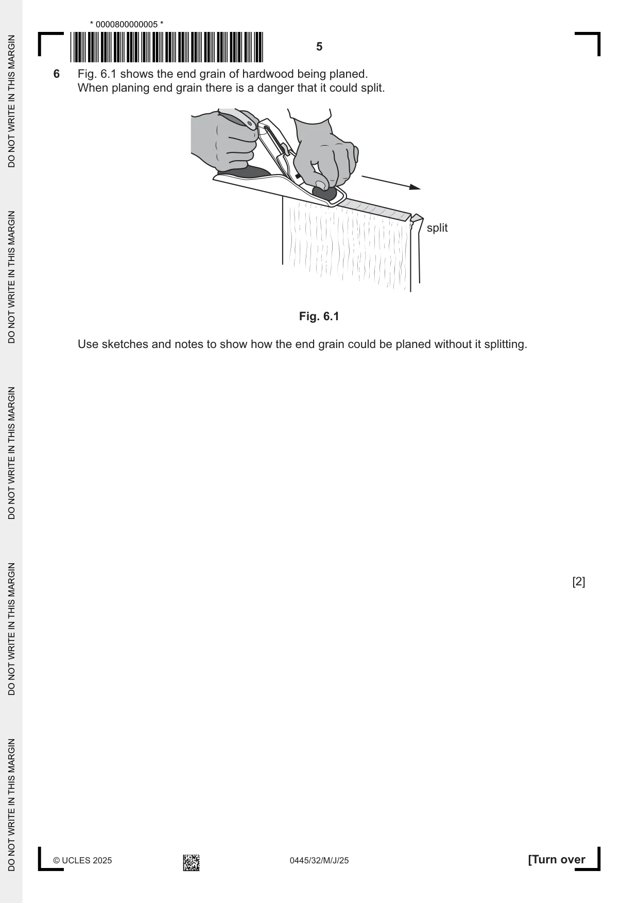
6 Fig. 6.1 shows the end grain of hardwood being planed. When planing end grain there is a danger that it could split. split Fig. 6.1 Use sketches and notes to show how the end grain could be planed without it splitting. [2]
Mark scheme: 6 Methods include: scrap wood clamped at end of board, 2 Award 0–2 dependent on technical accuracy plane to centre from both ends [0 – 2]
Q7 · A strip of metal that has been work hardened
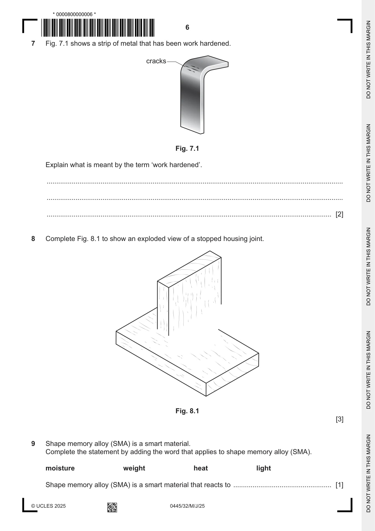
7 Fig. 7.1 shows a strip of metal that has been work hardened. cracks Fig. 7.1 Explain what is meant by the term ‘work hardened’. .......................................................................................................................................................... .......................................................................................................................................................... .................................................................................................................................................... [2]
Mark scheme: 7 Beaten or hammered [1] 2 Do not accept references to ‘heating’ metal Continuously or repeatedly [1]
Question 8
8 Complete Fig. 8.1 to show an exploded view of a stopped housing joint. Fig. 8.1 [3]
Mark scheme: 8 Stopped housing shown in lower board [1] 3 Do not accept through or double-stopped housings Stopped housing shown in upper board [1] Technical accuracy [1]
Q9 · Shape memory alloy (SMA) is a smart material
9 Shape memory alloy (SMA) is a smart material. Complete the statement by adding the word that applies to shape memory alloy (SMA). moisture weight heat light Shape memory alloy (SMA) is a smart material that reacts to ................................................... [1]
Mark scheme: 9 Heat 1
Q10 · Two children’s toy trucks
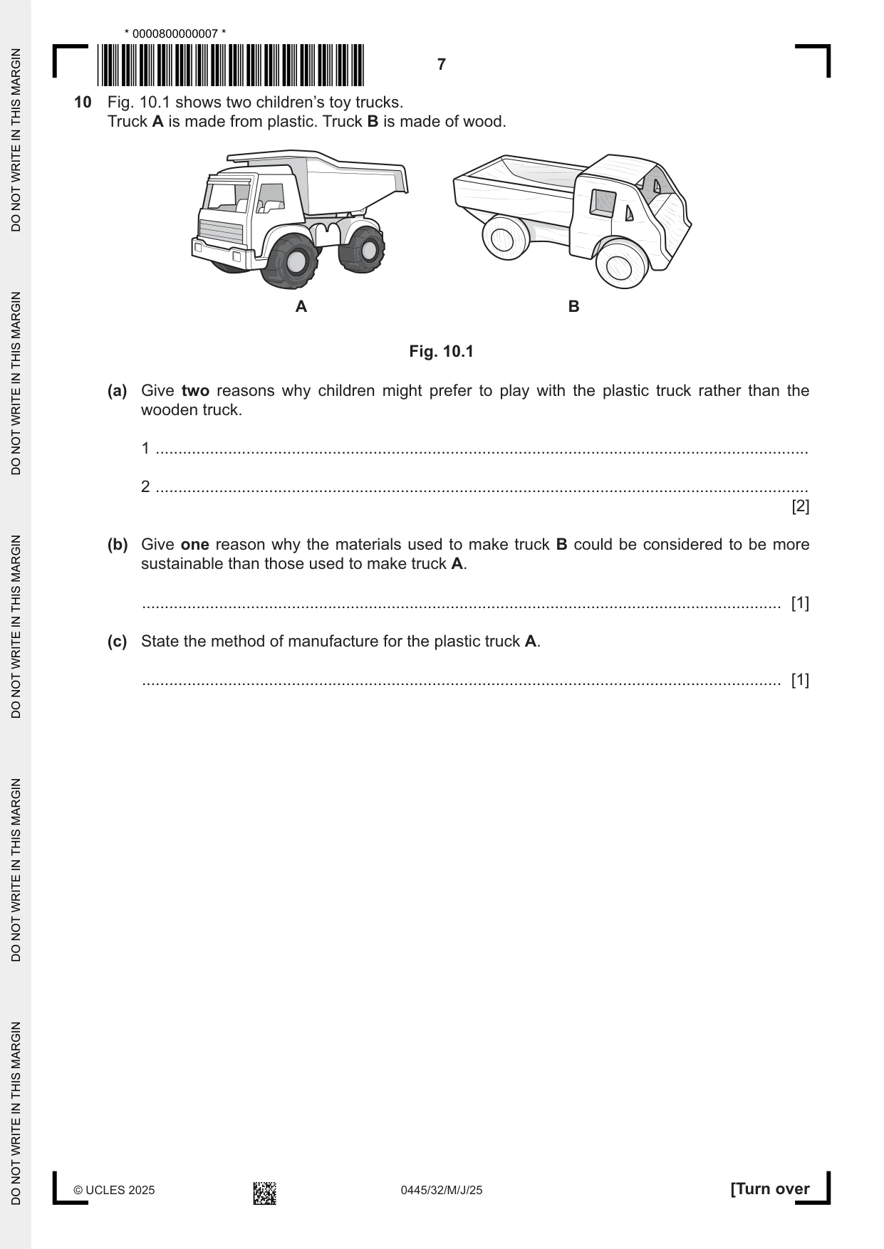
10 Fig. 10.1 shows two children’s toy trucks. Truck A is made from plastic. Truck B is made of wood. A B Fig. 10.1 (a) Give two reasons why children might prefer to play with the plastic truck rather than the wooden truck. 1 ................................................................................................................................................ 2 ................................................................................................................................................ [2] (b) Give one reason why the materials used to make truck B could be considered to be more sustainable than those used to make truck A. ............................................................................................................................................. [1] (c) State the method of manufacture for the plastic truck A. ............................................................................................................................................. [1]
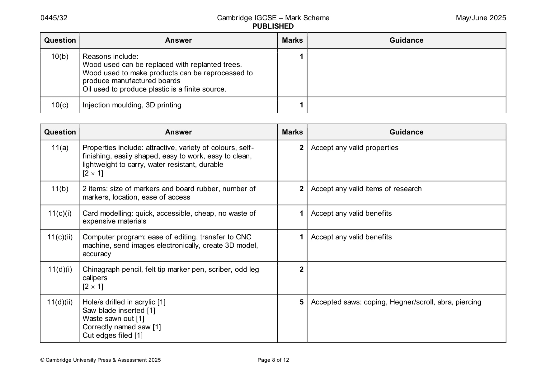
Mark scheme: 10(a) Reasons: bright colours, more intricate shapes, lighter to 2 Accept any valid reasons e.g.: child preferences handle, smoother, no splinters Do not accept ‘more attractive’ [2 1] 10(b) Reasons include: 1 Wood used can be replaced with replanted trees. Wood used to make products can be reprocessed to produce manufactured boards Oil used to produce plastic is a finite source. 10(c) Injection moulding, 3D printing 1
Q11 · A design for a rack to hold whiteboard marker pens and a board rubber
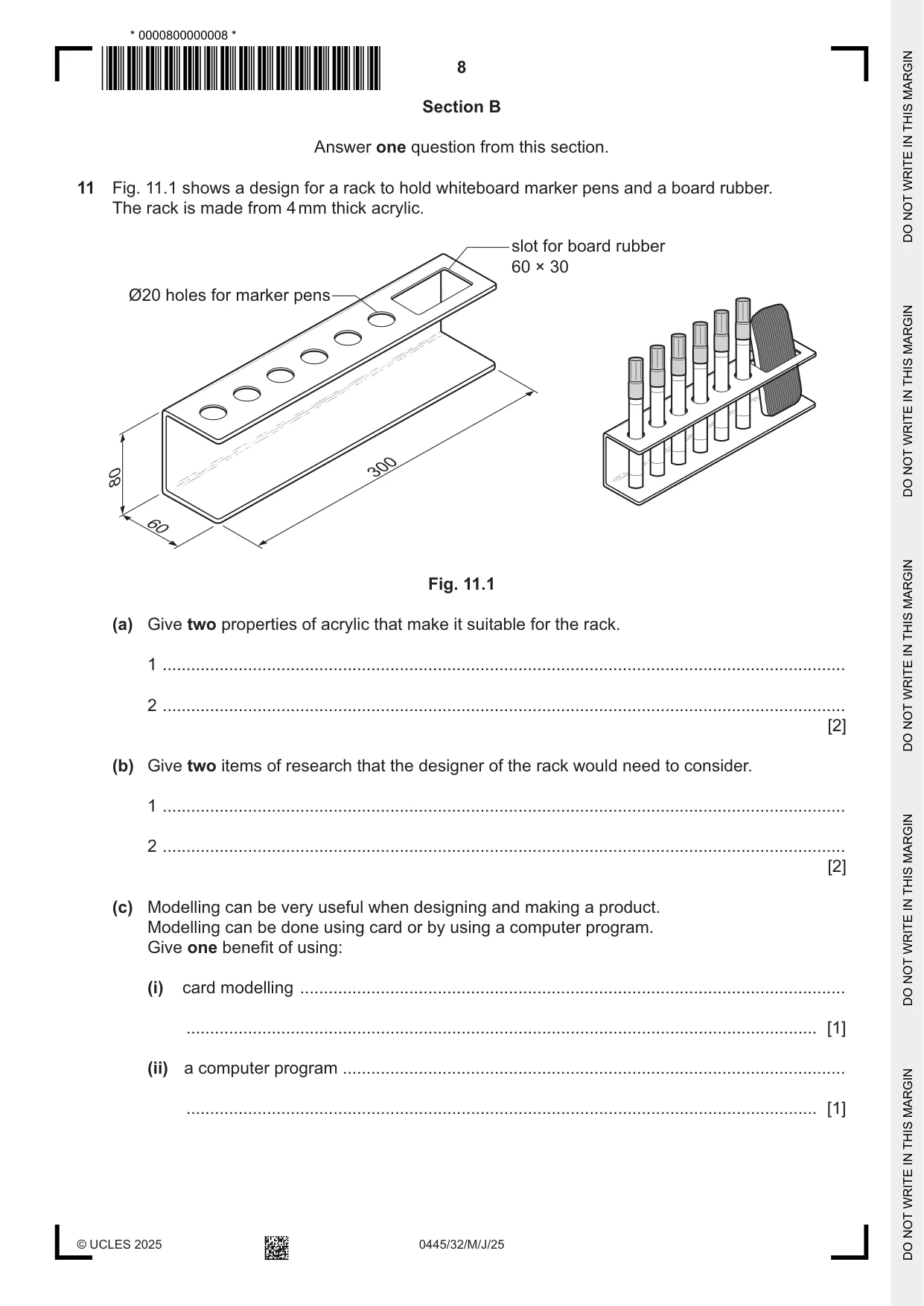
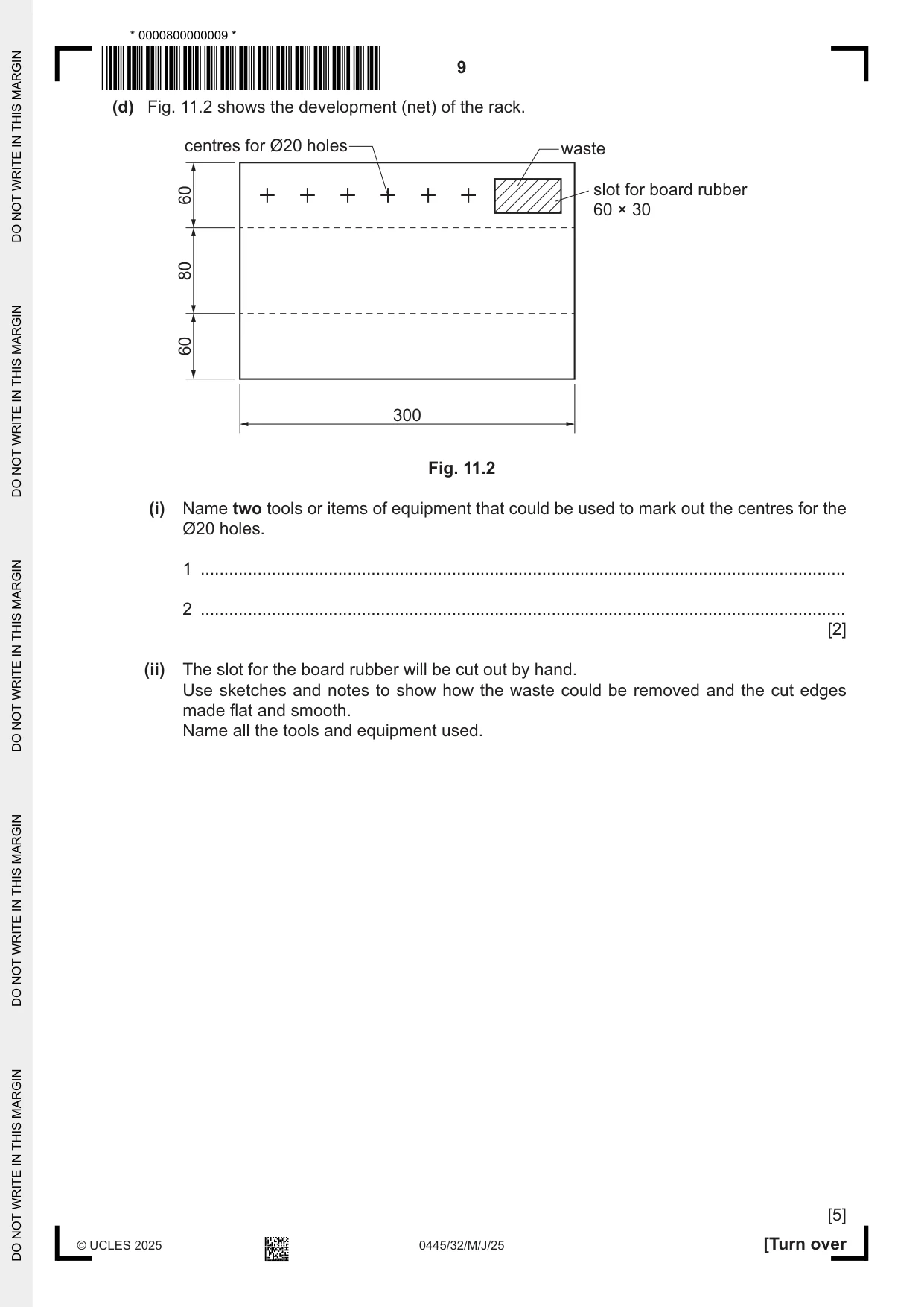
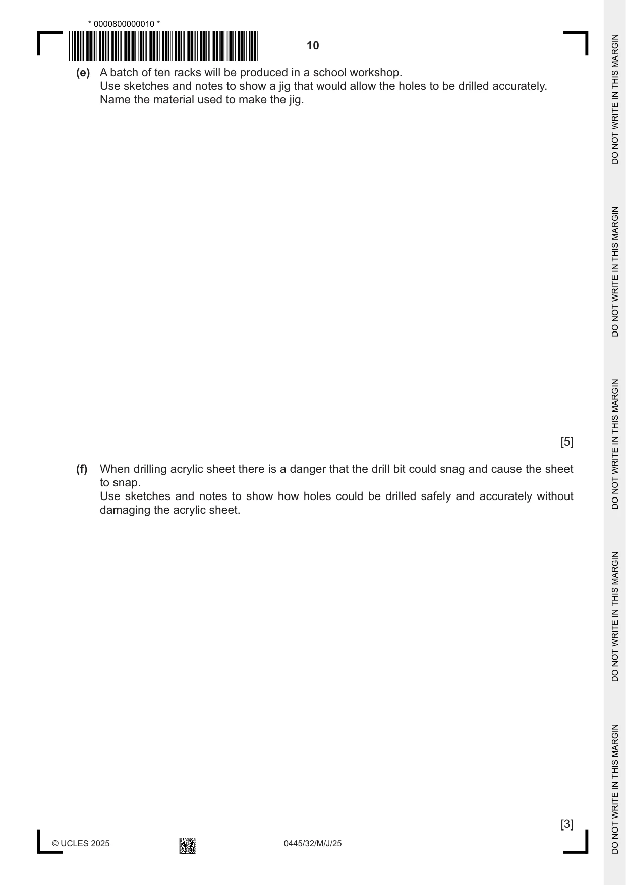
11 Fig. 11.1 shows a design for a rack to hold whiteboard marker pens and a board rubber. The rack is made from 4 mm thick acrylic. slot for board rubber 60 × 30 Ø20 holes for marker pens 300 80 60 Fig. 11.1 (a) Give two properties of acrylic that make it suitable for the rack. 1 ................................................................................................................................................ 2 ................................................................................................................................................ [2] (b) Give two items of research that the designer of the rack would need to consider. 1 ................................................................................................................................................ 2 ................................................................................................................................................ [2] (c) Modelling can be very useful when designing and making a product. Modelling can be done using card or by using a computer program. Give one benefit of using: (i) card modelling ................................................................................................................... ..................................................................................................................................... [1] (ii) a computer program .......................................................................................................... ..................................................................................................................................... [1] (d) Fig. 11.2 shows the development (net) of the rack. centres for Ø20 holes waste 60 slot for board rubber 60 × 30 80 60 300 Fig. 11.2 (i) Name two tools or items of equipment that could be used to mark out the centres for the Ø20 holes. 1 ........................................................................................................................................ 2 ........................................................................................................................................ [2] (ii) The slot for the board rubber will be cut out by hand. Use sketches and notes to show how the waste could be removed and the cut edges made flat and smooth. Name all the tools and equipment used. [5] (e) A batch of ten racks will be produced in a school workshop. Use sketches and notes to show a jig that would allow the holes to be drilled accurately. Name the material used to make the jig. [5] (f) When drilling acrylic sheet there is a danger that the drill bit could snag and cause the sheet to snap. Use sketches and notes to show how holes could be drilled safely and accurately without damaging the acrylic sheet. [3] (g) Use sketches and notes to show how the acrylic sheet could be bent to form the shape of the rack. Give details of all the equipment used. [4]
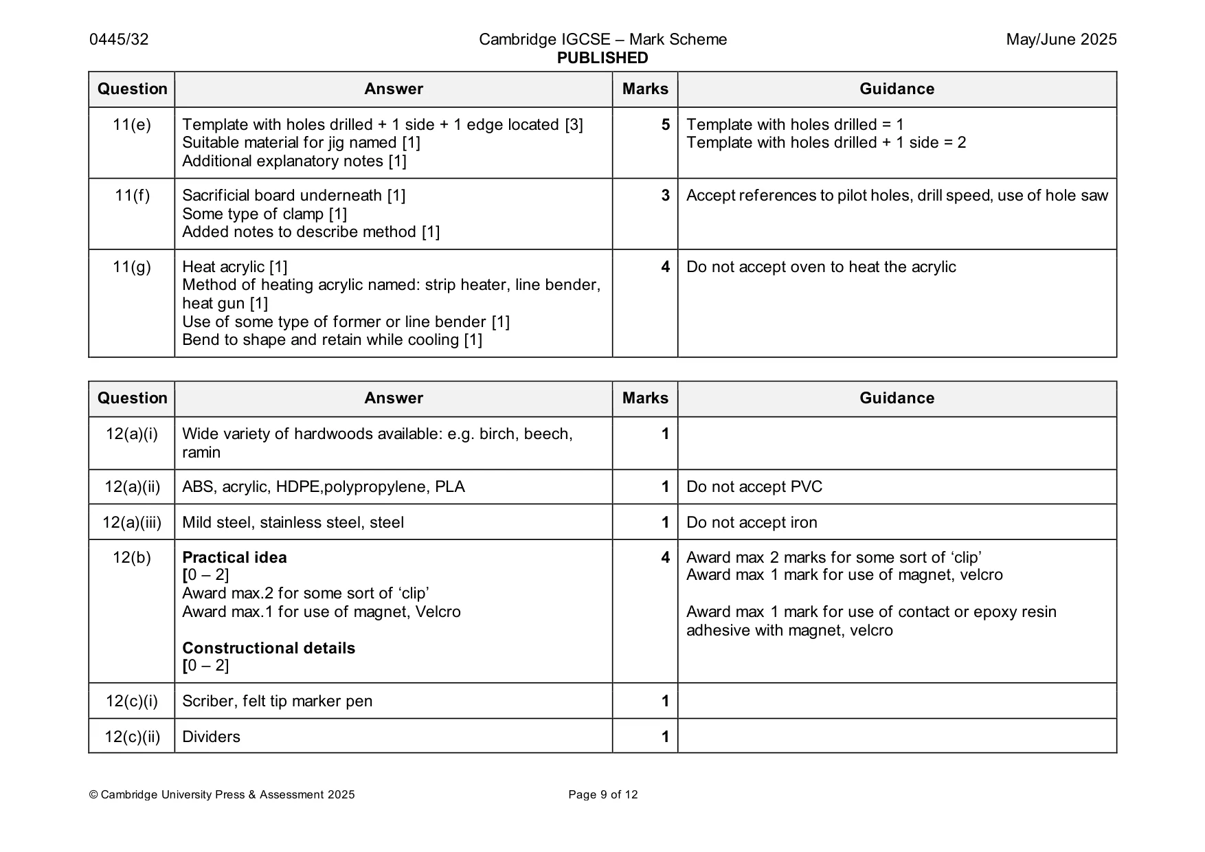
Mark scheme: 11(a) Properties include: attractive, variety of colours, self- 2 Accept any valid properties finishing, easily shaped, easy to work, easy to clean, lightweight to carry, water resistant, durable [2 1] 11(b) 2 items: size of markers and board rubber, number of 2 Accept any valid items of research markers, location, ease of access 11(c)(i) Card modelling: quick, accessible, cheap, no waste of 1 Accept any valid benefits expensive materials 11(c)(ii) Computer program: ease of editing, transfer to CNC 1 Accept any valid benefits machine, send images electronically, create 3D model, accuracy 11(d)(i) Chinagraph pencil, felt tip marker pen, scriber, odd leg 2 calipers [2 1] 11(d)(ii) Hole/s drilled in acrylic [1] 5 Accepted saws: coping, Hegner/scroll, abra, piercing Saw blade inserted [1] Waste sawn out [1] Correctly named saw [1] Cut edges filed [1] 11(e) Template with holes drilled + 1 side + 1 edge located [3] 5 Template with holes drilled = 1 Suitable material for jig named [1] Template with holes drilled + 1 side = 2 Additional explanatory notes [1] 11(f) Sacrificial board underneath [1] 3 Accept references to pilot holes, drill speed, use of hole saw Some type of clamp [1] Added notes to describe method [1] 11(g) Heat acrylic [1] 4 Do not accept oven to heat the acrylic Method of heating acrylic named: strip heater, line bender, heat gun [1] Use of some type of former or line bender [1] Bend to shape and retain while cooling [1]
Q12 · A design for a holder to contain salt and pepper shakers
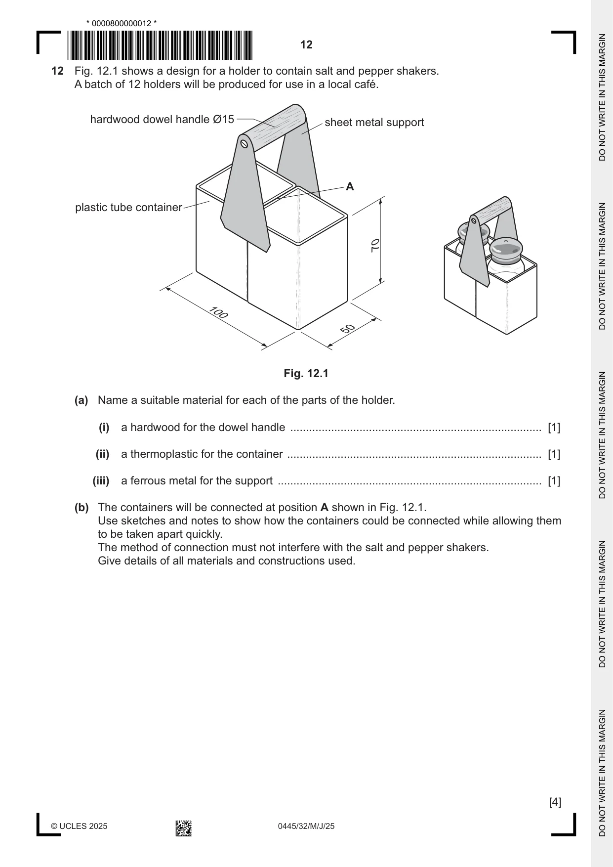
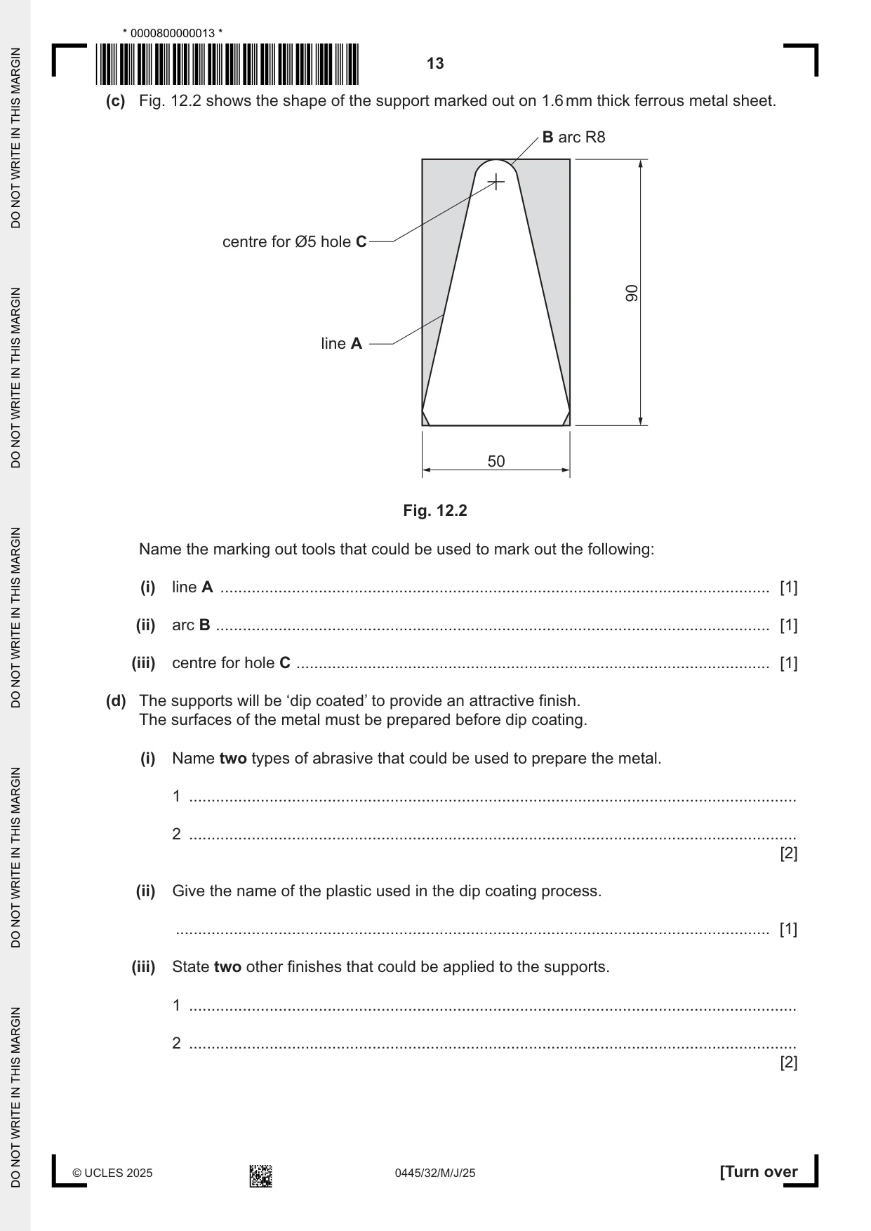
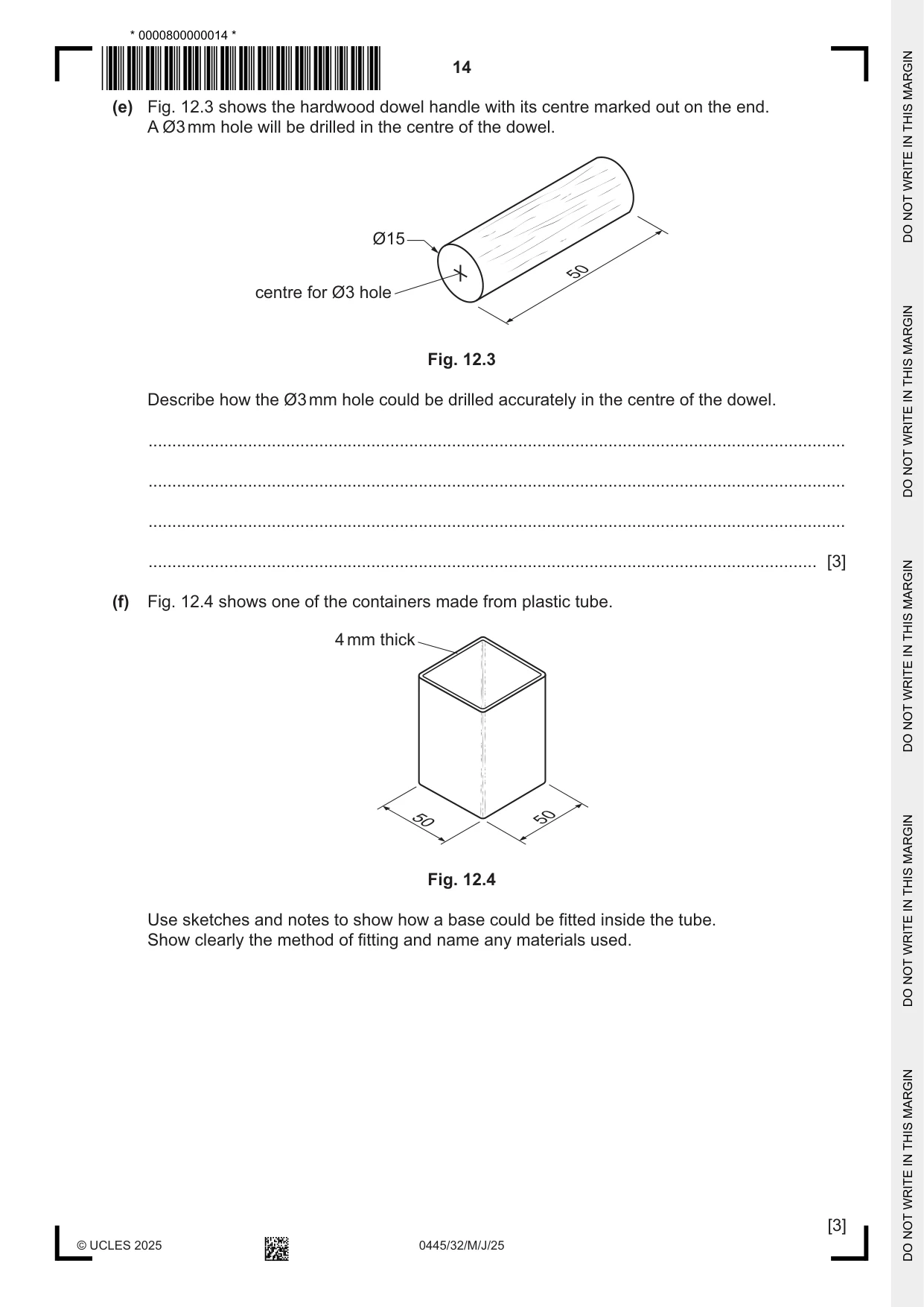
12 Fig. 12.1 shows a design for a holder to contain salt and pepper shakers. A batch of 12 holders will be produced for use in a local café. hardwood dowel handle Ø15 sheet metal support A plastic tube container 70 100 50 Fig. 12.1 (a) Name a suitable material for each of the parts of the holder. (i) a hardwood for the dowel handle ................................................................................ [1] (ii) a thermoplastic for the container ................................................................................. [1] (iii) a ferrous metal for the support .................................................................................... [1] (b) The containers will be connected at position A shown in Fig. 12.1. Use sketches and notes to show how the containers could be connected while allowing them to be taken apart quickly. The method of connection must not interfere with the salt and pepper shakers. Give details of all materials and constructions used. [4] (c) Fig. 12.2 shows the shape of the support marked out on 1.6 mm thick ferrous metal sheet. B arc R8 centre for Ø5 hole C 90 line A 50 Fig. 12.2 Name the marking out tools that could be used to mark out the following: (i) line A ........................................................................................................................... [1] (ii) arc B ............................................................................................................................ [1] (iii) centre for hole C .......................................................................................................... [1] (d) The supports will be ‘dip coated’ to provide an attractive finish. The surfaces of the metal must be prepared before dip coating. (i) Name two types of abrasive that could be used to prepare the metal. 1 ........................................................................................................................................ 2 ........................................................................................................................................ [2] (ii) Give the name of the plastic used in the dip coating process. ..................................................................................................................................... [1] (iii) State two other finishes that could be applied to the supports. 1 ........................................................................................................................................ 2 ........................................................................................................................................ [2] (e) Fig. 12.3 shows the hardwood dowel handle with its centre marked out on the end. A Ø3 mm hole will be drilled in the centre of the dowel. Ø15 50 centre for Ø3 hole Fig. 12.3 Describe how the Ø3 mm hole could be drilled accurately in the centre of the dowel. ................................................................................................................................................... ................................................................................................................................................... ................................................................................................................................................... ............................................................................................................................................. [3] (f) Fig. 12.4 shows one of the containers made from plastic tube. 4 mm thick 50 50 Fig. 12.4 Use sketches and notes to show how a base could be fitted inside the tube. Show clearly the method of fitting and name any materials used. [3] (g) Three different materials have been used to produce the holder for the salt and pepper shakers. The only material that could be considered sustainable is the dowel used for the handle. Explain why: (i) sheet metal could not be considered a sustainable material. ........................................................................................................................................... ........................................................................................................................................... ..................................................................................................................................... [2] (ii) plastic could not be considered a sustainable material. ........................................................................................................................................... ........................................................................................................................................... ..................................................................................................................................... [2]
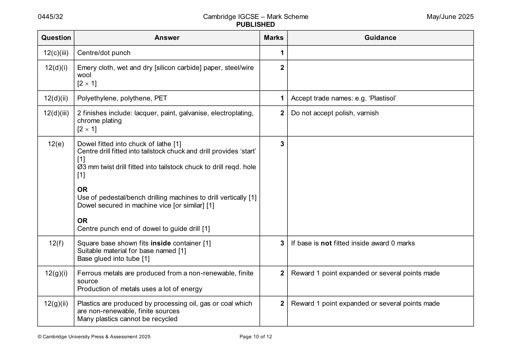
Mark scheme: 12(a)(i) Wide variety of hardwoods available: e.g. birch, beech, 1 ramin 12(a)(ii) ABS, acrylic, HDPE,polypropylene, PLA 1 Do not accept PVC 12(a)(iii) Mild steel, stainless steel, steel 1 Do not accept iron 12(b) Practical idea 4 Award max 2 marks for some sort of ‘clip’ [0 – 2] Award max 1 mark for use of magnet, velcro Award max.2 for some sort of ‘clip’ Award max.1 for use of magnet, Velcro Award max 1 mark for use of contact or epoxy resin adhesive with magnet, velcro Constructional details [0 – 2] 12(c)(i) Scriber, felt tip marker pen 1 12(c)(ii) Dividers 1 12(c)(iii) Centre/dot punch 1 12(d)(i) Emery cloth, wet and dry [silicon carbide] paper, steel/wire 2 wool [2 1] 12(d)(ii) Polyethylene, polythene, PET 1 Accept trade names: e.g. ‘Plastisol’ 12(d)(iii) 2 finishes include: lacquer, paint, galvanise, electroplating, 2 Do not accept polish, varnish chrome plating [2 1] 12(e) Dowel fitted into chuck of lathe [1] 3 Centre drill fitted into tailstock chuck and drill provides ‘start’ [1] Ø3 mm twist drill fitted into tailstock chuck to drill reqd. hole [1] OR Use of pedestal/bench drilling machines to drill vertically [1] Dowel secured in machine vice [or similar] [1] OR Centre punch end of dowel to guide drill [1] 12(f) Square base shown fits inside container [1] 3 If base is not fitted inside award 0 marks Suitable material for base named [1] Base glued into tube [1] 12(g)(i) Ferrous metals are produced from a non-renewable, finite 2 Reward 1 point expanded or several points made source Production of metals uses a lot of energy 12(g)(ii) Plastics are produced by processing oil, gas or coal which 2 Reward 1 point expanded or several points made are non-renewable, finite sources Many plastics cannot be recycled
Q13 · Views of a desk made of wood
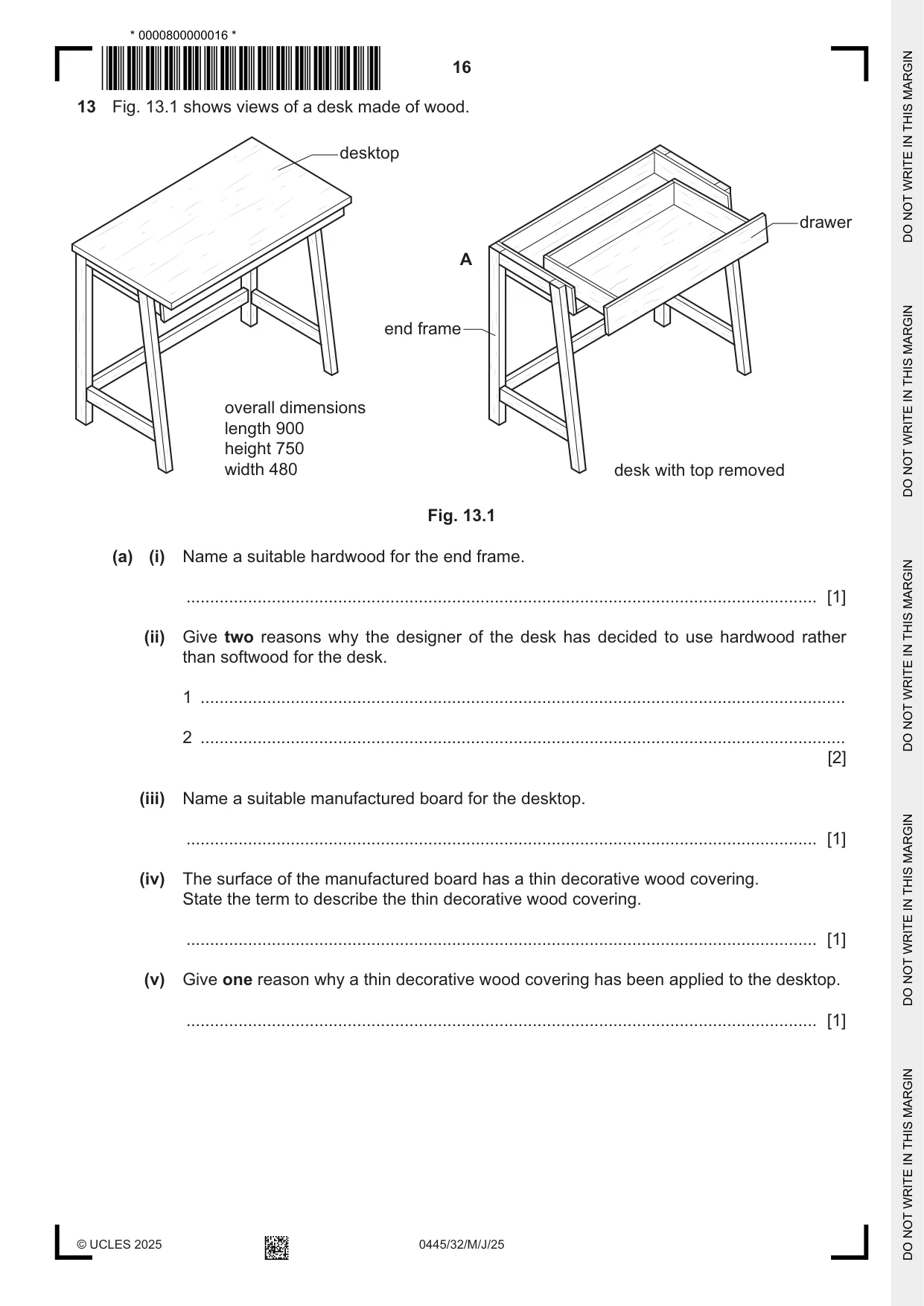
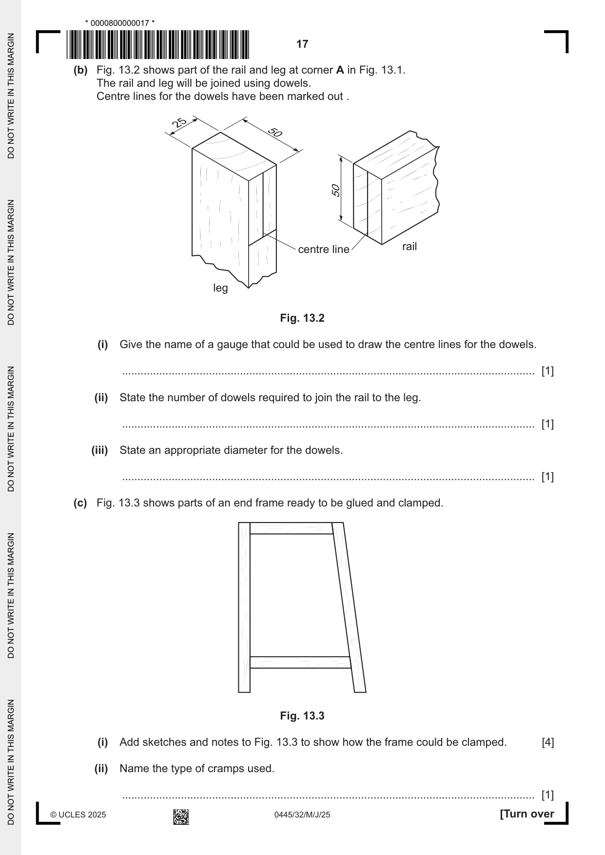
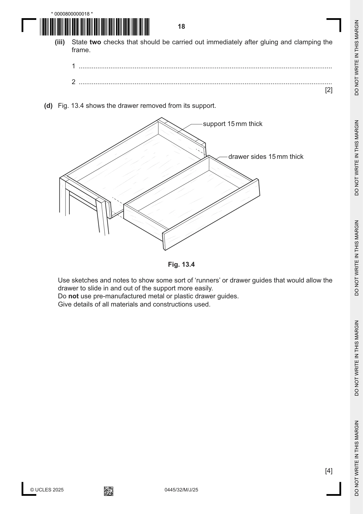
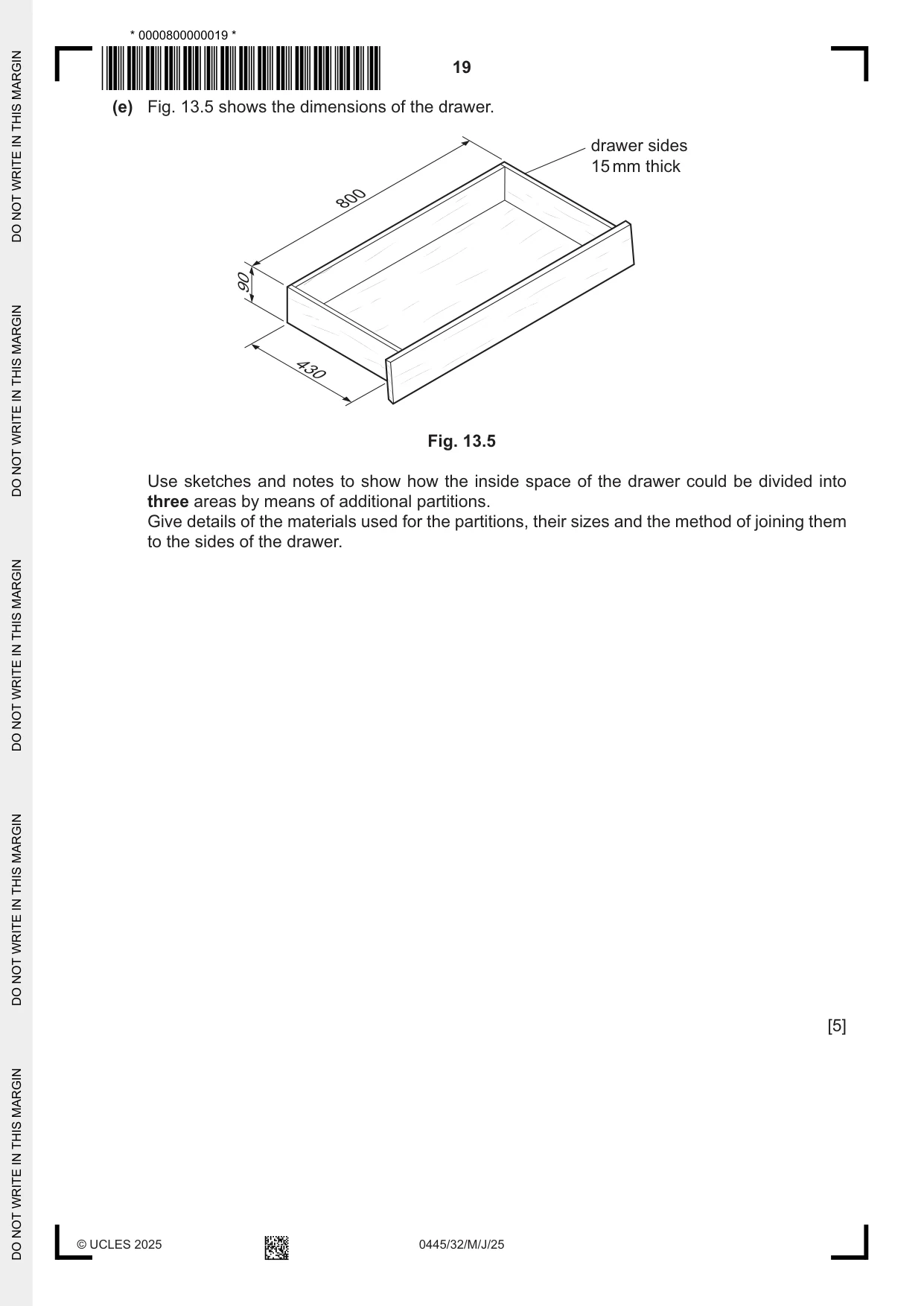
13 Fig. 13.1 shows views of a desk made of wood. desktop drawer A end frame overall dimensions length 900 height 750 width 480 desk with top removed Fig. 13.1 (a) (i) Name a suitable hardwood for the end frame. ..................................................................................................................................... [1] (ii) Give two reasons why the designer of the desk has decided to use hardwood rather than softwood for the desk. 1 ........................................................................................................................................ 2 ........................................................................................................................................ [2] (iii) Name a suitable manufactured board for the desktop. ..................................................................................................................................... [1] (iv) The surface of the manufactured board has a thin decorative wood covering. State the term to describe the thin decorative wood covering. ..................................................................................................................................... [1] (v) Give one reason why a thin decorative wood covering has been applied to the desktop. ..................................................................................................................................... [1] (b) Fig. 13.2 shows part of the rail and leg at corner A in Fig. 13.1. The rail and leg will be joined using dowels. Centre lines for the dowels have been marked out . 25 50 50 centre line rail leg Fig. 13.2 (i) Give the name of a gauge that could be used to draw the centre lines for the dowels. ..................................................................................................................................... [1] (ii) State the number of dowels required to join the rail to the leg. ..................................................................................................................................... [1] (iii) State an appropriate diameter for the dowels. ..................................................................................................................................... [1] (c) Fig. 13.3 shows parts of an end frame ready to be glued and clamped. Fig. 13.3 (i) Add sketches and notes to Fig. 13.3 to show how the frame could be clamped. [4] (ii) Name the type of cramps used. ..................................................................................................................................... [1] (iii) State two checks that should be carried out immediately after gluing and clamping the frame. 1 ........................................................................................................................................ 2 ........................................................................................................................................ [2] (d) Fig. 13.4 shows the drawer removed from its support. support 15 mm thick drawer sides 15 mm thick Fig. 13.4 Use sketches and notes to show some sort of ‘runners’ or drawer guides that would allow the drawer to slide in and out of the support more easily. Do not use pre-manufactured metal or plastic drawer guides. Give details of all materials and constructions used. [4]
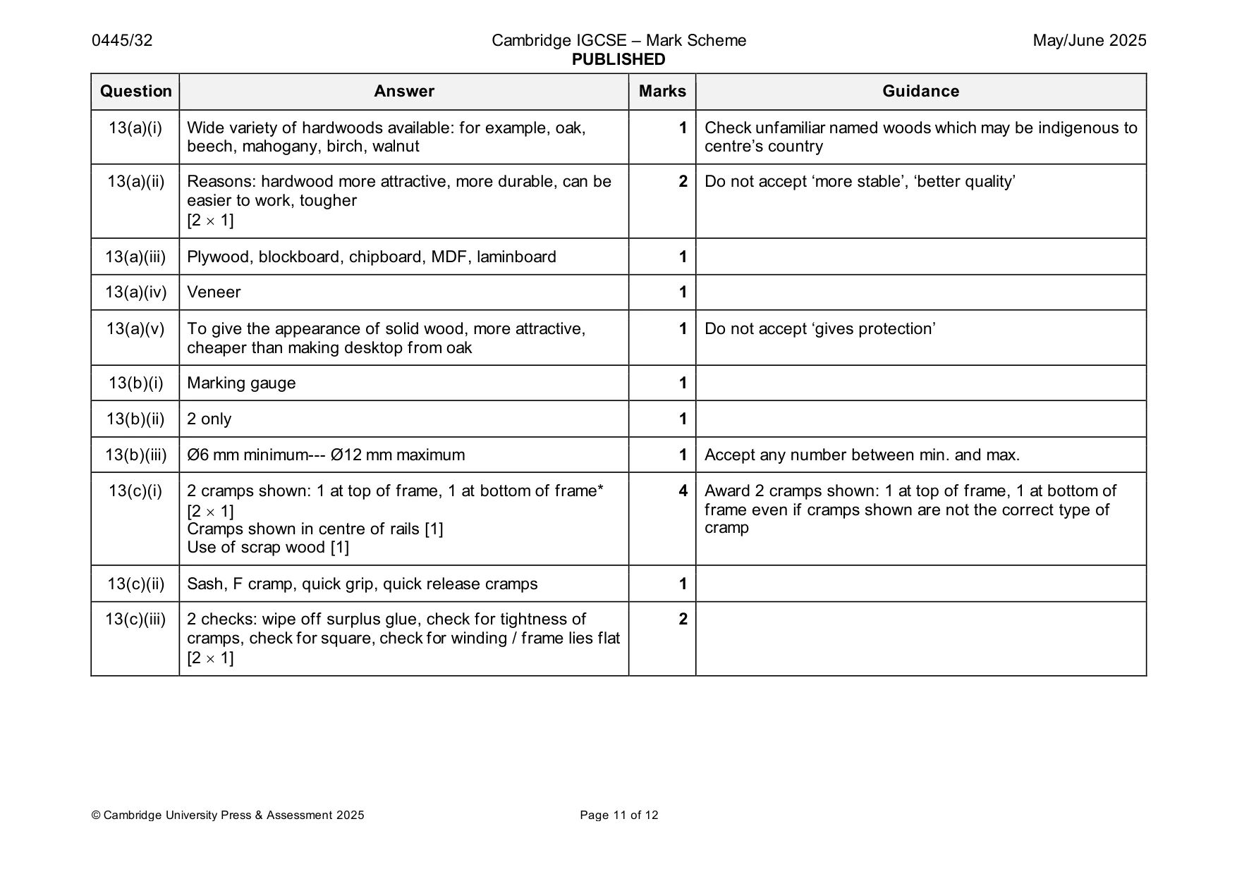
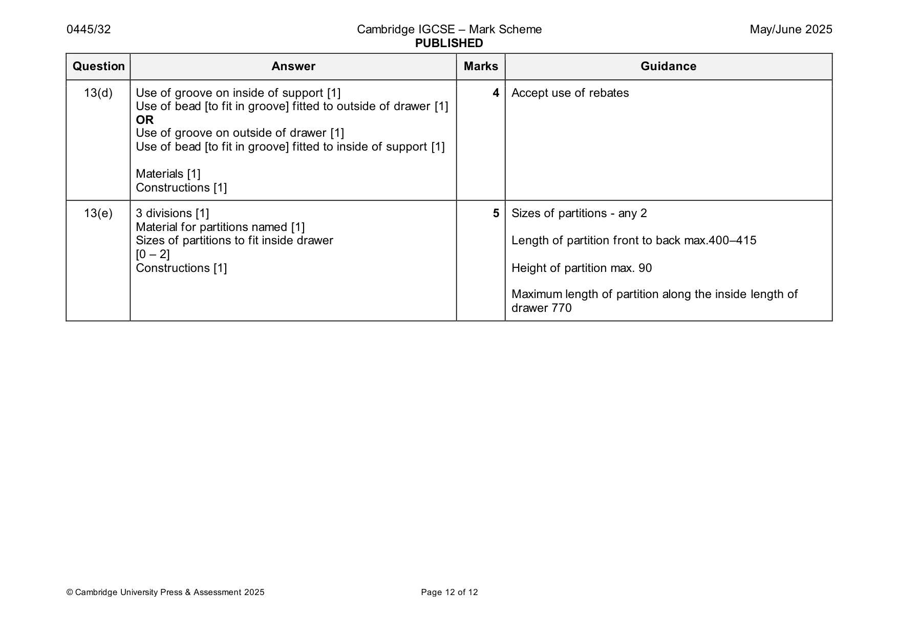
Mark scheme: 13(a)(i) Wide variety of hardwoods available: for example, oak, 1 Check unfamiliar named woods which may be indigenous to beech, mahogany, birch, walnut centre’s country 13(a)(ii) Reasons: hardwood more attractive, more durable, can be 2 Do not accept ‘more stable’, ‘better quality’ easier to work, tougher [2 1] 13(a)(iii) Plywood, blockboard, chipboard, MDF, laminboard 1 13(a)(iv) Veneer 1 13(a)(v) To give the appearance of solid wood, more attractive, 1 Do not accept ‘gives protection’ cheaper than making desktop from oak 13(b)(i) Marking gauge 1 13(b)(ii) 2 only 1 13(b)(iii) Ø6 mm minimum--- Ø12 mm maximum 1 Accept any number between min. and max. 13(c)(i) 2 cramps shown: 1 at top of frame, 1 at bottom of frame* 4 Award 2 cramps shown: 1 at top of frame, 1 at bottom of [2 1] frame even if cramps shown are not the correct type of Cramps shown in centre of rails [1] cramp Use of scrap wood [1] 13(c)(ii) Sash, F cramp, quick grip, quick release cramps 1 13(c)(iii) 2 checks: wipe off surplus glue, check for tightness of 2 cramps, check for square, check for winding / frame lies flat [2 1] 13(d) Use of groove on inside of support [1] 4 Accept use of rebates Use of bead [to fit in groove] fitted to outside of drawer [1] OR Use of groove on outside of drawer [1] Use of bead [to fit in groove] fitted to inside of support [1] Materials [1] Constructions [1] 13(e) 3 divisions [1] 5 Sizes of partitions - any 2 Material for partitions named [1] Sizes of partitions to fit inside drawer Length of partition front to back max.400–415 [0 – 2] Constructions [1] Height of partition max. 90 Maximum length of partition along the inside length of drawer 770
What was in this paper
The subtopics covered by these 13 questions, and how many questions each got. Open one in a new tab to see every Cambridge question on it.
What you needed in this session
Cambridge’s own grade thresholds for 2025 May/June, Paper 3 · Variant 2. A higher threshold means an easier paper — the bar moves with how the cohort did.