Cambridge IGCSE Design and Technology 0445 — 2022 May/June Paper 3 · Variant 2
0445/32/M/J/22 · 13 questions · 50 marks · ≈56 min
The question paper and its mark scheme, free to read here and free to download. This is Cambridge’s own paper, exactly as it was sat.
Question paper24 pages
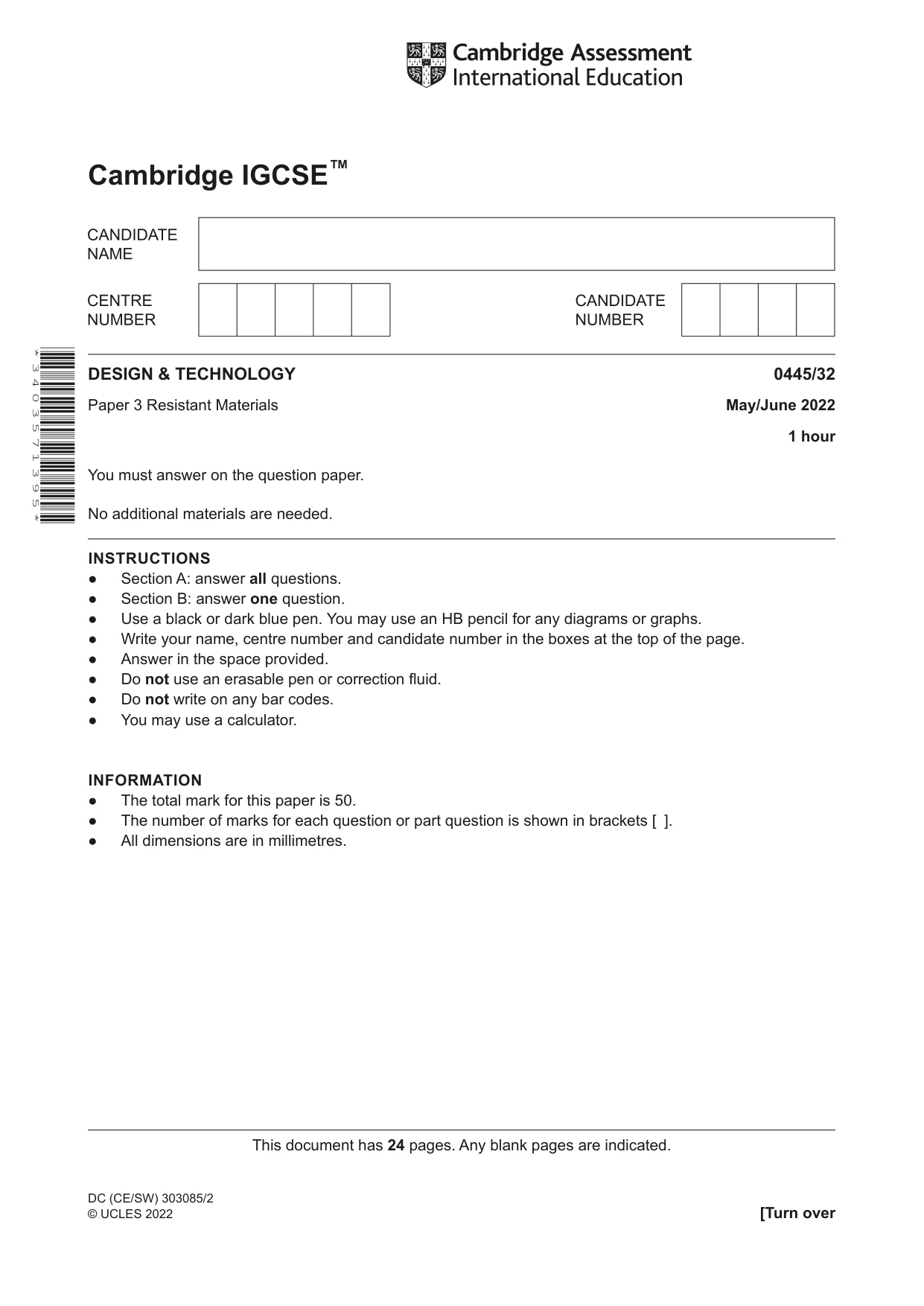
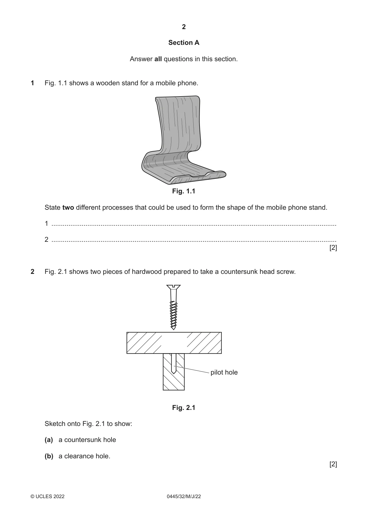
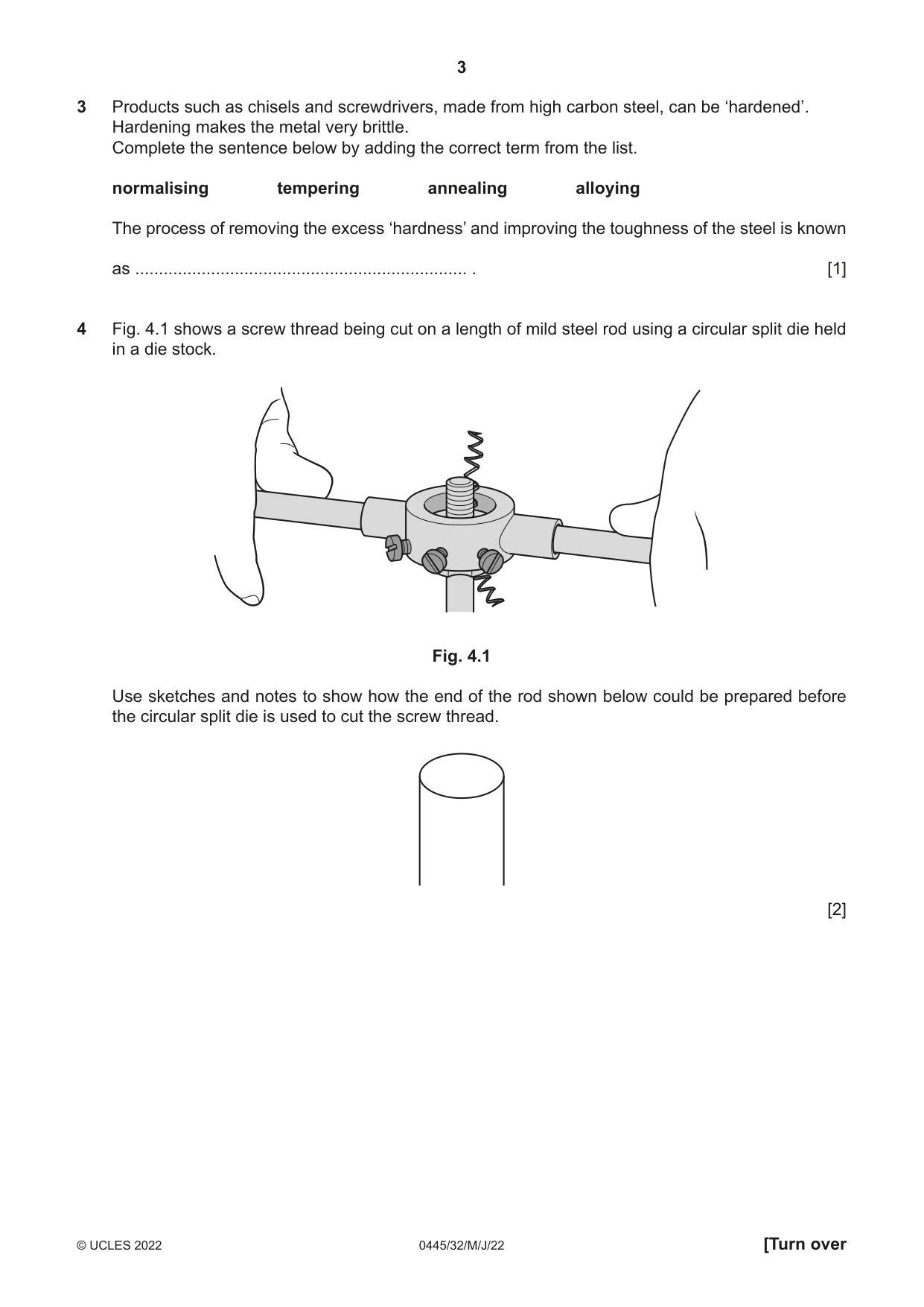
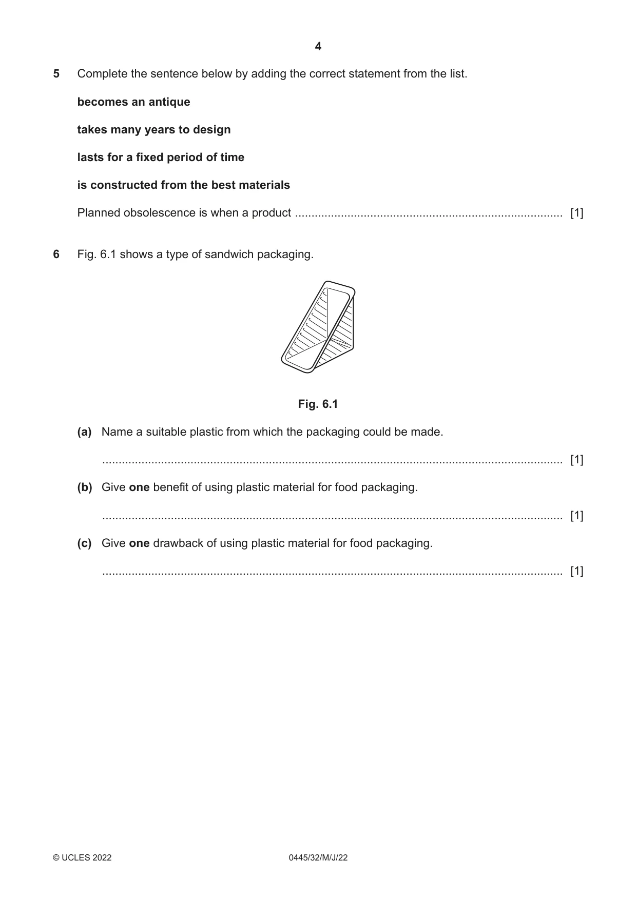
Mark scheme9 pages
Answers below. Sit the paper first if you are practising.
Questions as text
Q1 · A wooden stand for a mobile phone
1 Fig. 1.1 shows a wooden stand for a mobile phone. Fig. 1.1 State two different processes that could be used to form the shape of the mobile phone stand. 1 ....................................................................................................................................................... 2 ....................................................................................................................................................... [2]
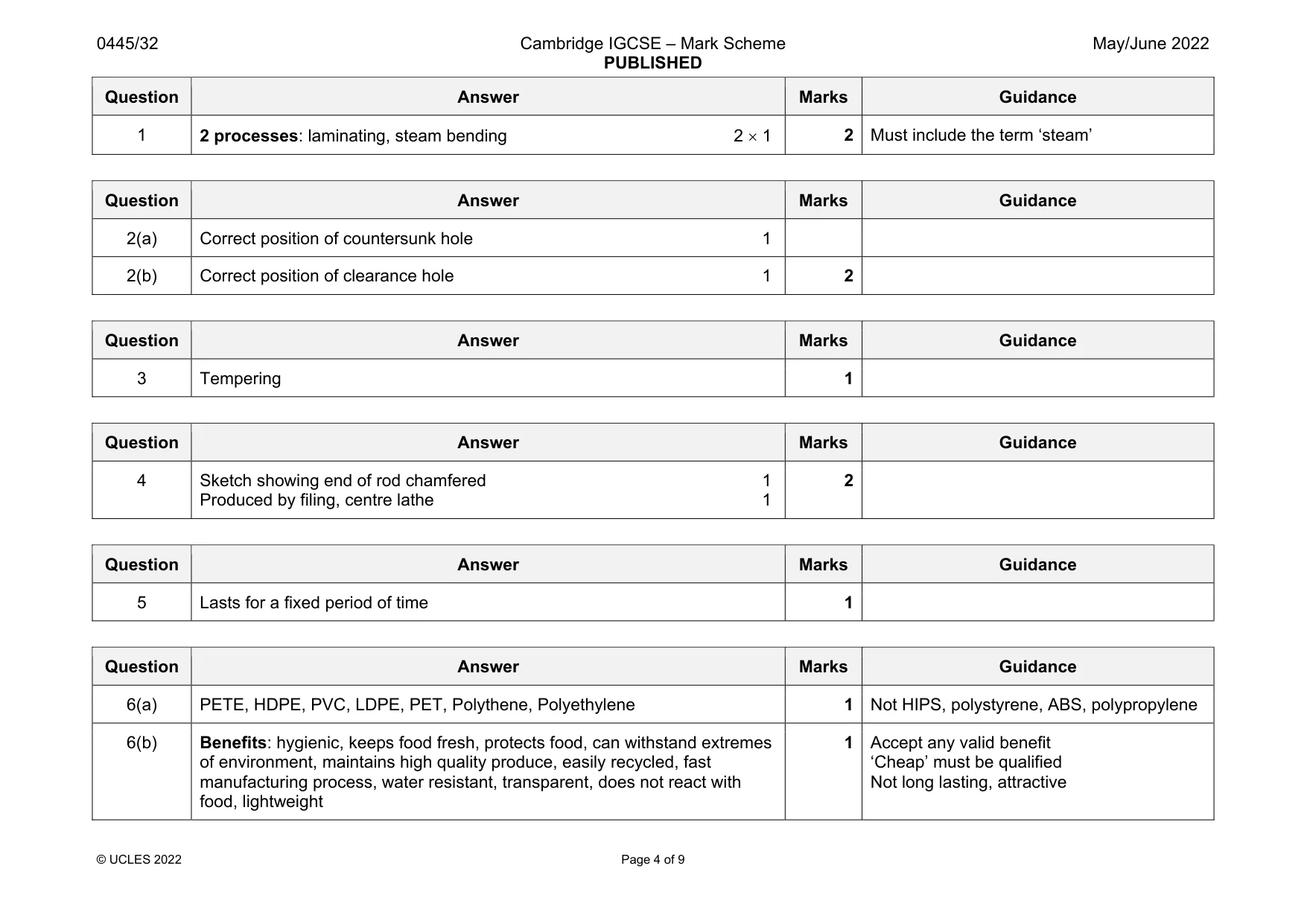
Mark scheme: 1 2 processes: laminating, steam bending 2 Must include the term ‘steam’
Q2 · Two pieces of hardwood prepared to take a countersunk head screw
2 Fig. 2.1 shows two pieces of hardwood prepared to take a countersunk head screw. pilot hole Fig. 2.1 Sketch onto Fig. 2.1 to show: (a) a countersunk hole (b) a clearance hole. [2]
Mark scheme: 2(a) Correct position of countersunk hole 1 2(b) Correct position of clearance hole 1 2
Q3 · Products such as chisels and screwdrivers, made from high carbon steel, can be ‘hardened’
3 Products such as chisels and screwdrivers, made from high carbon steel, can be ‘hardened’. Hardening makes the metal very brittle. Complete the sentence below by adding the correct term from the list. normalising tempering annealing alloying The process of removing the excess ‘hardness’ and improving the toughness of the steel is known as ...................................................................... . [1]
Mark scheme: 3 Tempering 1
Q4 · A screw thread being cut on a length of mild steel rod using a circular split die held in…
4 Fig. 4.1 shows a screw thread being cut on a length of mild steel rod using a circular split die held in a die stock. Fig. 4.1 Use sketches and notes to show how the end of the rod shown below could be prepared before the circular split die is used to cut the screw thread. [2]
Mark scheme: 4 Sketch showing end of rod chamfered 1 Produced by filing, centre lathe 1 2
Q5 · Complete the sentence below by adding the correct statement from the list
5 Complete the sentence below by adding the correct statement from the list. becomes an antique takes many years to design lasts for a fixed period of time is constructed from the best materials Planned obsolescence is when a product .................................................................................. [1]
Mark scheme: 5 Lasts for a fixed period of time 1
Q6 · A type of sandwich packaging
6 Fig. 6.1 shows a type of sandwich packaging. Fig. 6.1 (a) Name a suitable plastic from which the packaging could be made. ............................................................................................................................................. [1] (b) Give one benefit of using plastic material for food packaging. ............................................................................................................................................. [1] (c) Give one drawback of using plastic material for food packaging. ............................................................................................................................................. [1]
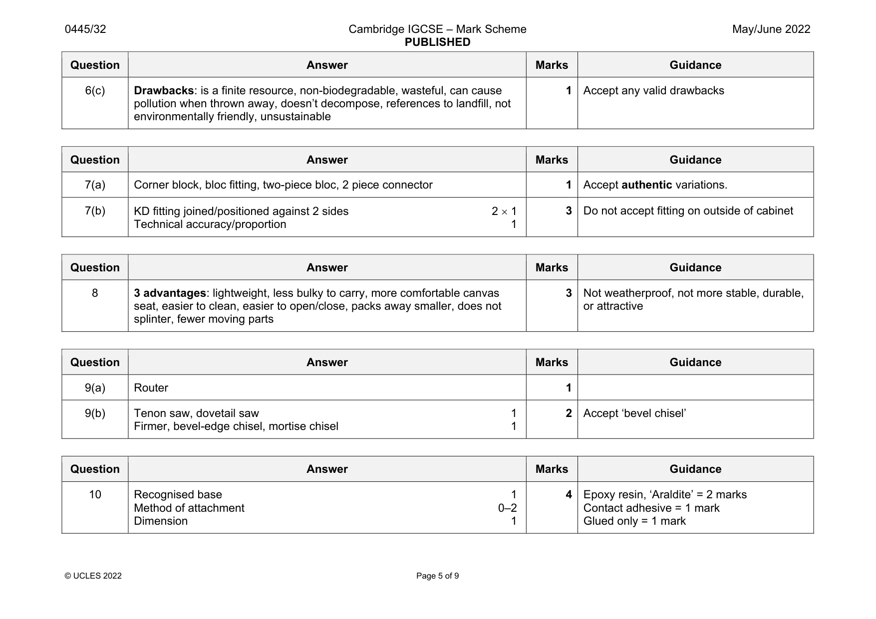
Mark scheme: 6(a) PETE, HDPE, PVC, LDPE, PET, Polythene, Polyethylene 1 Not HIPS, polystyrene, ABS, polypropylene 6(b) Benefits: hygienic, keeps food fresh, protects food, can withstand extremes of environment, maintains high quality produce, easily recycled, fast manufacturing process, water resistant, transparent, does not react with food, lightweight 1 Accept any valid benefit ‘Cheap’ must be qualified Not long lasting, attractive Question Answer Marks Guidance 6(c) Drawbacks: is a finite resource, non-biodegradable, wasteful, can cause pollution when thrown away, doesn’t decompose, references to landfill, not environmentally friendly, unsustainable 1 Accept any valid drawbacks
Q7 · A knock-down (KD) fitting
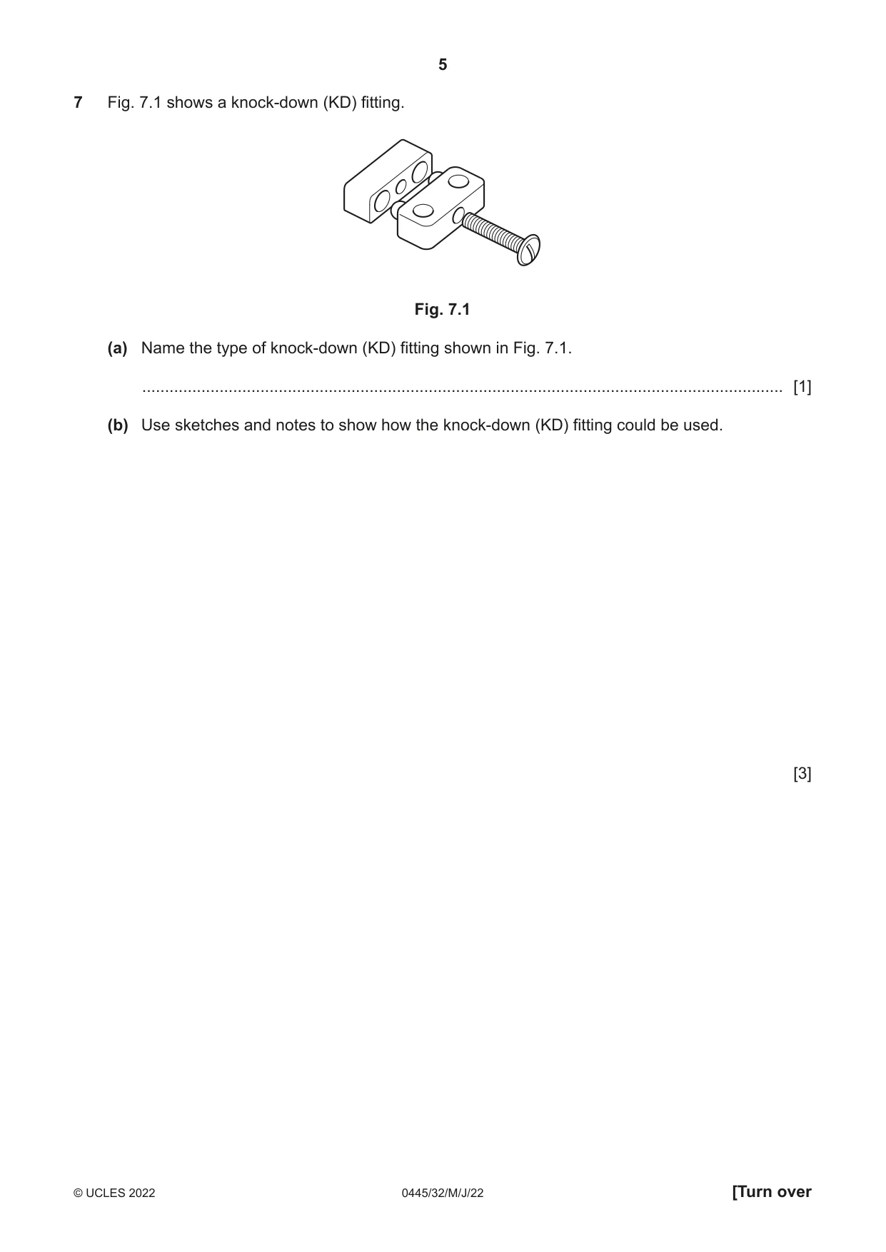
7 Fig. 7.1 shows a knock-down (KD) fitting. Fig. 7.1 (a) Name the type of knock-down (KD) fitting shown in Fig. 7.1. ............................................................................................................................................. [1] (b) Use sketches and notes to show how the knock-down (KD) fitting could be used. [3]
Mark scheme: 7(a) Corner block, bloc fitting, two-piece bloc, 2 piece connector 1 Accept authentic variations. 7(b) KD fitting joined/positioned against 2 sides 2 1 Technical accuracy/proportion 1 3 Do not accept fitting on outside of cabinet
Q8 · Two camping stools, A and B
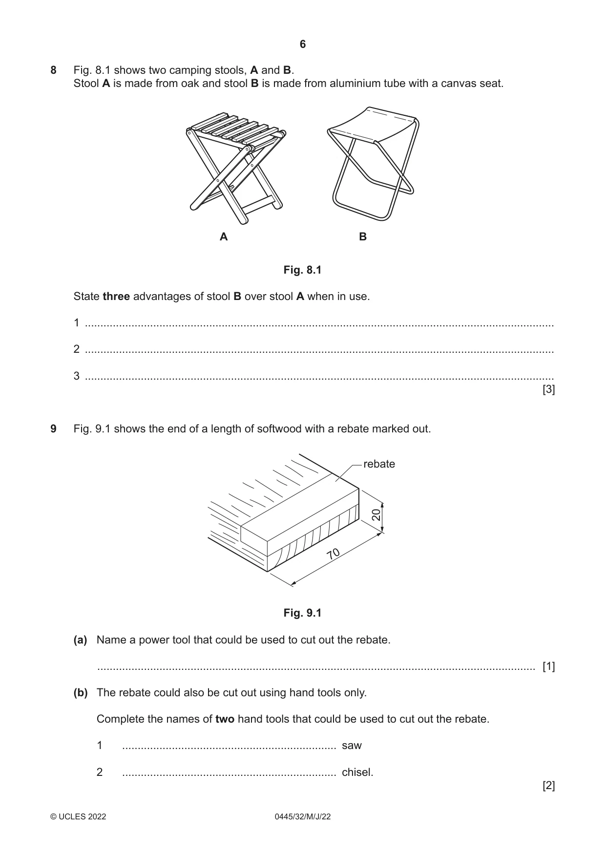
8 Fig. 8.1 shows two camping stools, A and B. Stool A is made from oak and stool B is made from aluminium tube with a canvas seat. A B Fig. 8.1 State three advantages of stool B over stool A when in use. 1 ....................................................................................................................................................... 2 ....................................................................................................................................................... 3 ....................................................................................................................................................... [3]
Mark scheme: 8 3 advantages: lightweight, less bulky to carry, more comfortable canvas seat, easier to clean, easier to open/close, packs away smaller, does not splinter, fewer moving parts 3 Not weatherproof, not more stable, durable, or attractive
Q9 · The end of a length of softwood with a rebate marked out
9 Fig. 9.1 shows the end of a length of softwood with a rebate marked out. rebate 20 70 Fig. 9.1 (a) Name a power tool that could be used to cut out the rebate. ............................................................................................................................................. [1] (b) The rebate could also be cut out using hand tools only. Complete the names of two hand tools that could be used to cut out the rebate. 1 ..................................................................... saw 2 ..................................................................... chisel. [2]
Mark scheme: 9(a) Router 1 9(b) Tenon saw, dovetail saw 1 Firmer, bevel-edge chisel, mortise chisel 1 2 Accept ‘bevel chisel’
Q10 · An incomplete design for a trophy made from 1 mm thick brass
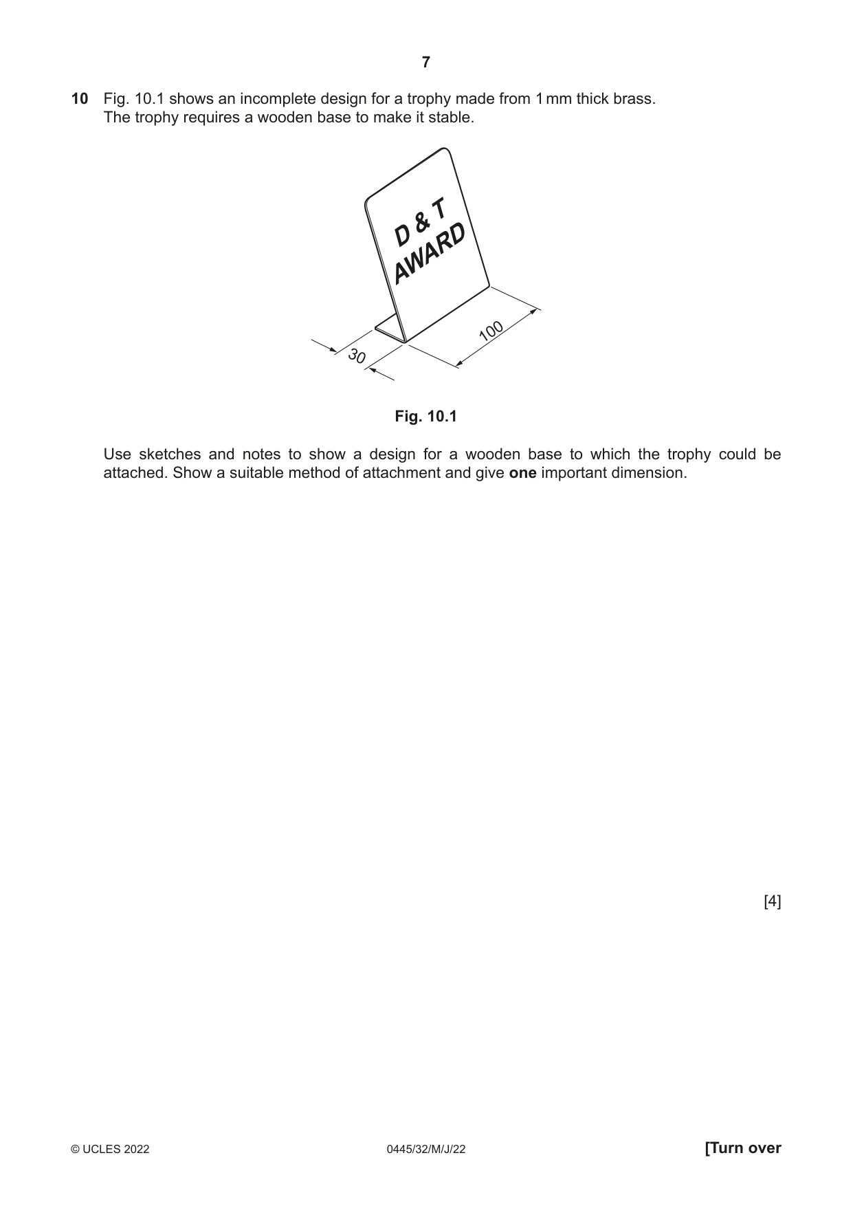
10 Fig. 10.1 shows an incomplete design for a trophy made from 1 mm thick brass. The trophy requires a wooden base to make it stable. T & AWARDD 100 30 Fig. 10.1 Use sketches and notes to show a design for a wooden base to which the trophy could be attached. Show a suitable method of attachment and give one important dimension. [4]
Mark scheme: 10 Recognised base 1 Method of attachment 0–2 Dimension 1 4 Epoxy resin, ‘Araldite’ = 2 marks Contact adhesive = 1 mark Glued only = 1 mark
Q11 · Views and details of a garden lantern
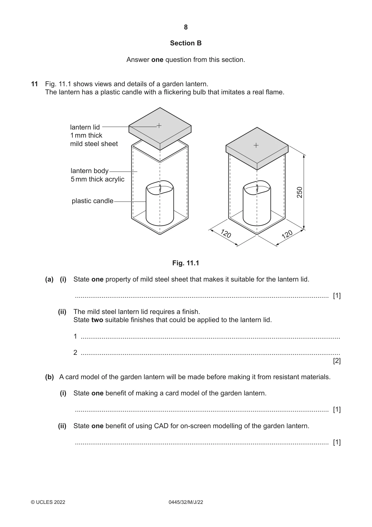
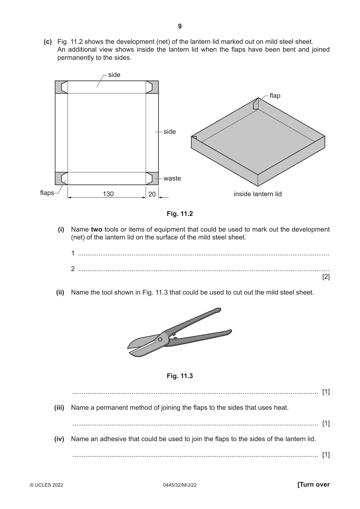
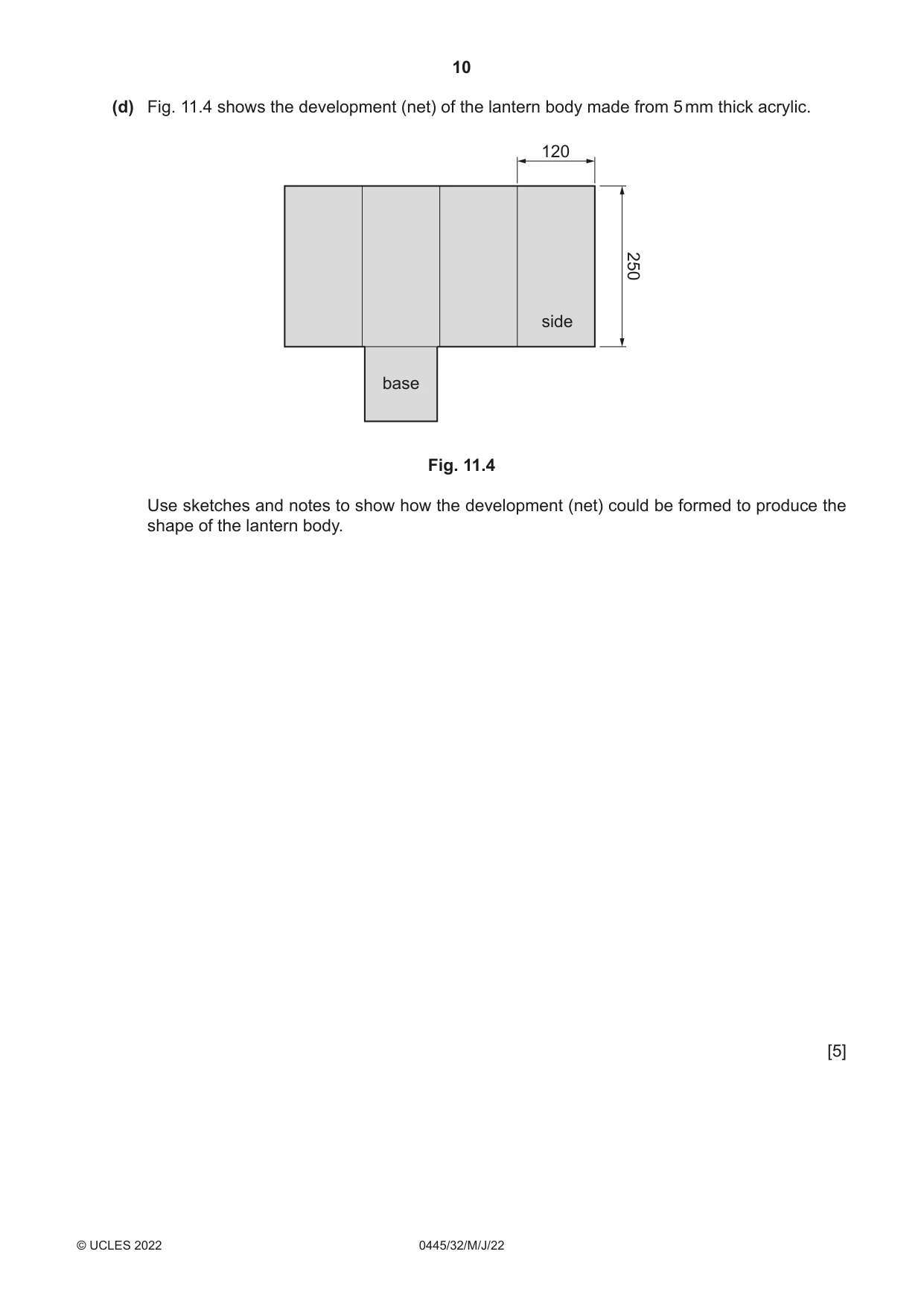
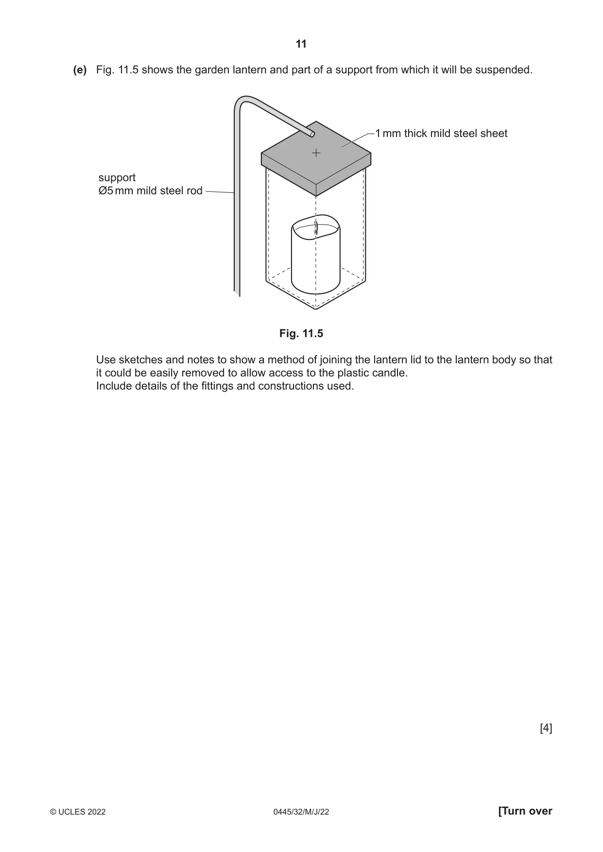
11 Fig. 11.1 shows views and details of a garden lantern. The lantern has a plastic candle with a flickering bulb that imitates a real flame. lantern lid 1 mm thick mild steel sheet lantern body 5 mm thick acrylic 250 plastic candle 120 120 Fig. 11.1 (a) (i) State one property of mild steel sheet that makes it suitable for the lantern lid. ..................................................................................................................................... [1] (ii) The mild steel lantern lid requires a finish. State two suitable finishes that could be applied to the lantern lid. 1 ........................................................................................................................................ 2 ........................................................................................................................................ [2] (b) A card model of the garden lantern will be made before making it from resistant materials. (i) State one benefit of making a card model of the garden lantern. ..................................................................................................................................... [1] (ii) State one benefit of using CAD for on-screen modelling of the garden lantern. ..................................................................................................................................... [1] (c) Fig. 11.2 shows the development (net) of the lantern lid marked out on mild steel sheet. An additional view shows inside the lantern lid when the flaps have been bent and joined permanently to the sides. side flap side waste flaps 130 20 inside lantern lid Fig. 11.2 (i) Name two tools or items of equipment that could be used to mark out the development (net) of the lantern lid on the surface of the mild steel sheet. 1 ........................................................................................................................................ 2 ........................................................................................................................................ [2] (ii) Name the tool shown in Fig. 11.3 that could be used to cut out the mild steel sheet. Fig. 11.3 ..................................................................................................................................... [1] (iii) Name a permanent method of joining the flaps to the sides that uses heat. ..................................................................................................................................... [1] (iv) Name an adhesive that could be used to join the flaps to the sides of the lantern lid. ..................................................................................................................................... [1] (d) Fig. 11.4 shows the development (net) of the lantern body made from 5 mm thick acrylic. 120 250 side base Fig. 11.4 Use sketches and notes to show how the development (net) could be formed to produce the shape of the lantern body. [5] (e) Fig. 11.5 shows the garden lantern and part of a support from which it will be suspended. 1 mm thick mild steel sheet support Ø5 mm mild steel rod Fig. 11.5 Use sketches and notes to show a method of joining the lantern lid to the lantern body so that it could be easily removed to allow access to the plastic candle. Include details of the fittings and constructions used. [4] (f) Use sketches and notes to show modifications to the lantern lid and the end of the support shown in Fig. 11.5 so that the garden lantern could be suspended safely. The modifications must allow the garden lantern to be detached from the support. Include details of the materials, fittings and constructions used. [6]
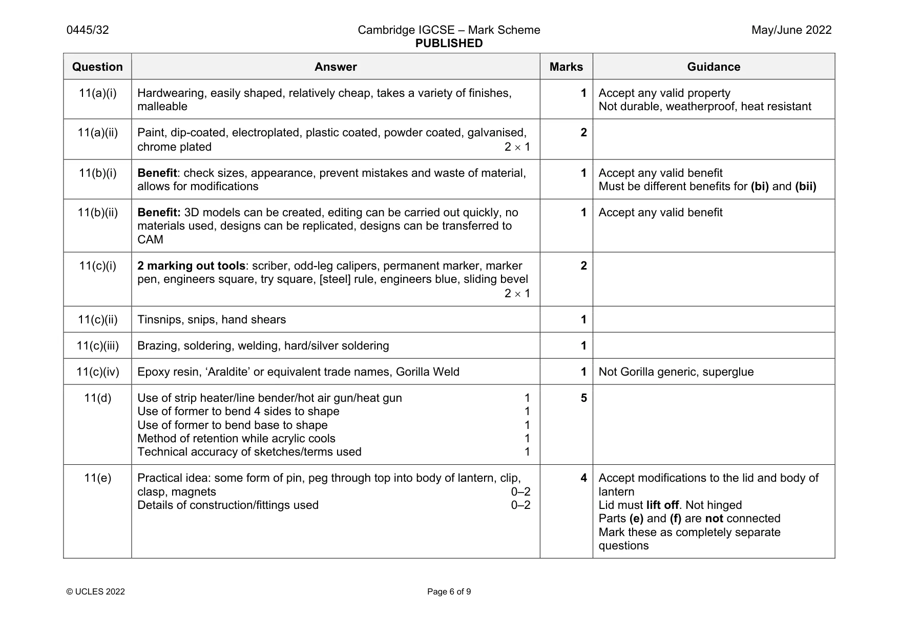
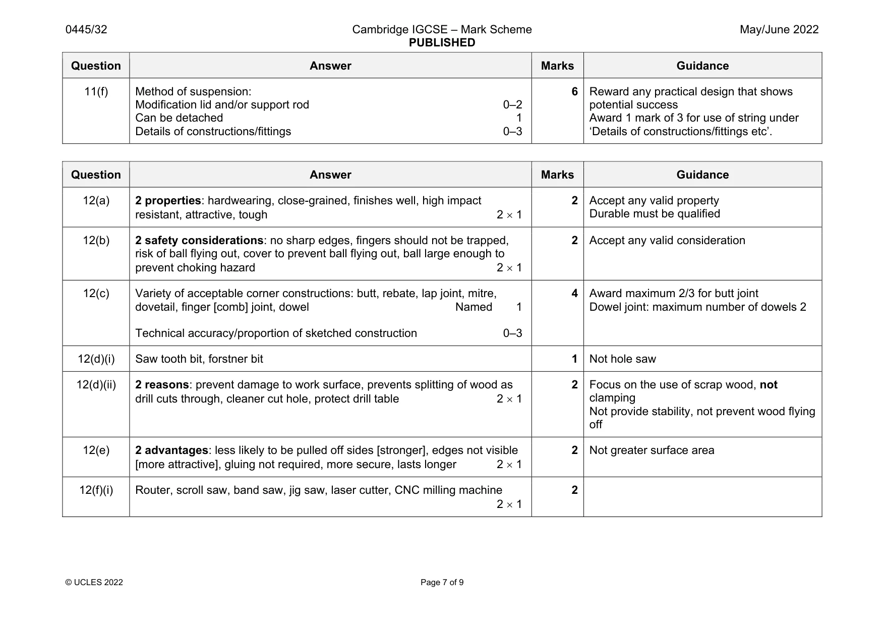
Mark scheme: 11(a)(i) Hardwearing, easily shaped, relatively cheap, takes a variety of finishes, malleable 1 Accept any valid property Not durable, weatherproof, heat resistant 11(a)(ii) Paint, dip-coated, electroplated, plastic coated, powder coated, galvanised, chrome plated 2 1 2 11(b)(i) Benefit: check sizes, appearance, prevent mistakes and waste of material, allows for modifications 1 Accept any valid benefit Must be different benefits for (bi) and (bii) 11(b)(ii) Benefit: 3D models can be created, editing can be carried out quickly, no materials used, designs can be replicated, designs can be transferred to CAM 1 Accept any valid benefit 11(c)(i) 2 marking out tools: scriber, odd-leg calipers, permanent marker, marker pen, engineers square, try square, [steel] rule, engineers blue, sliding bevel 2 1 2 11(c)(ii) Tinsnips, snips, hand shears 1 11(c)(iii) Brazing, soldering, welding, hard/silver soldering 1 11(c)(iv) Epoxy resin, ‘Araldite’ or equivalent trade names, Gorilla Weld 1 Not Gorilla generic, superglue 11(d) Use of strip heater/line bender/hot air gun/heat gun 1 Use of former to bend 4 sides to shape 1 Use of former to bend base to shape 1 Method of retention while acrylic cools 1 Technical accuracy of sketches/terms used 1 5 11(e) Practical idea: some form of pin, peg through top into body of lantern, clip, clasp, magnets 0–2 Details of construction/fittings used 0–2 4 Accept modifications to the lid and body of lantern Lid must lift off. Not hinged Parts (e) and (f) are not connected Mark these as completely separate questions Question Answer Marks Guidance 11(f) Method of suspension: Modification lid and/or support rod 0–2 Can be detached 1 Details of constructions/fittings 0–3 6 Reward any practical design that shows potential success Award 1 mark of 3 for use of string under ‘Details of constructions/fittings etc’.
Q12 · An incomplete design for a pinball game
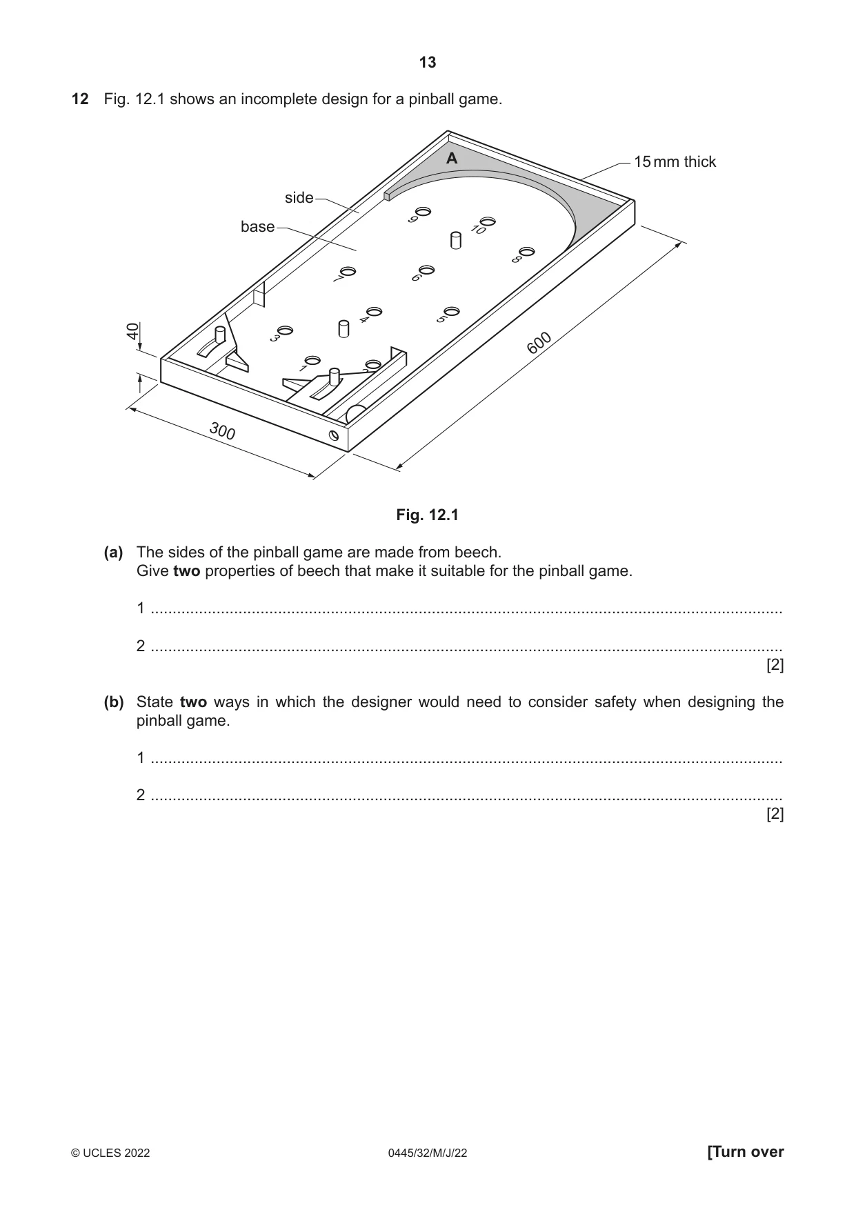
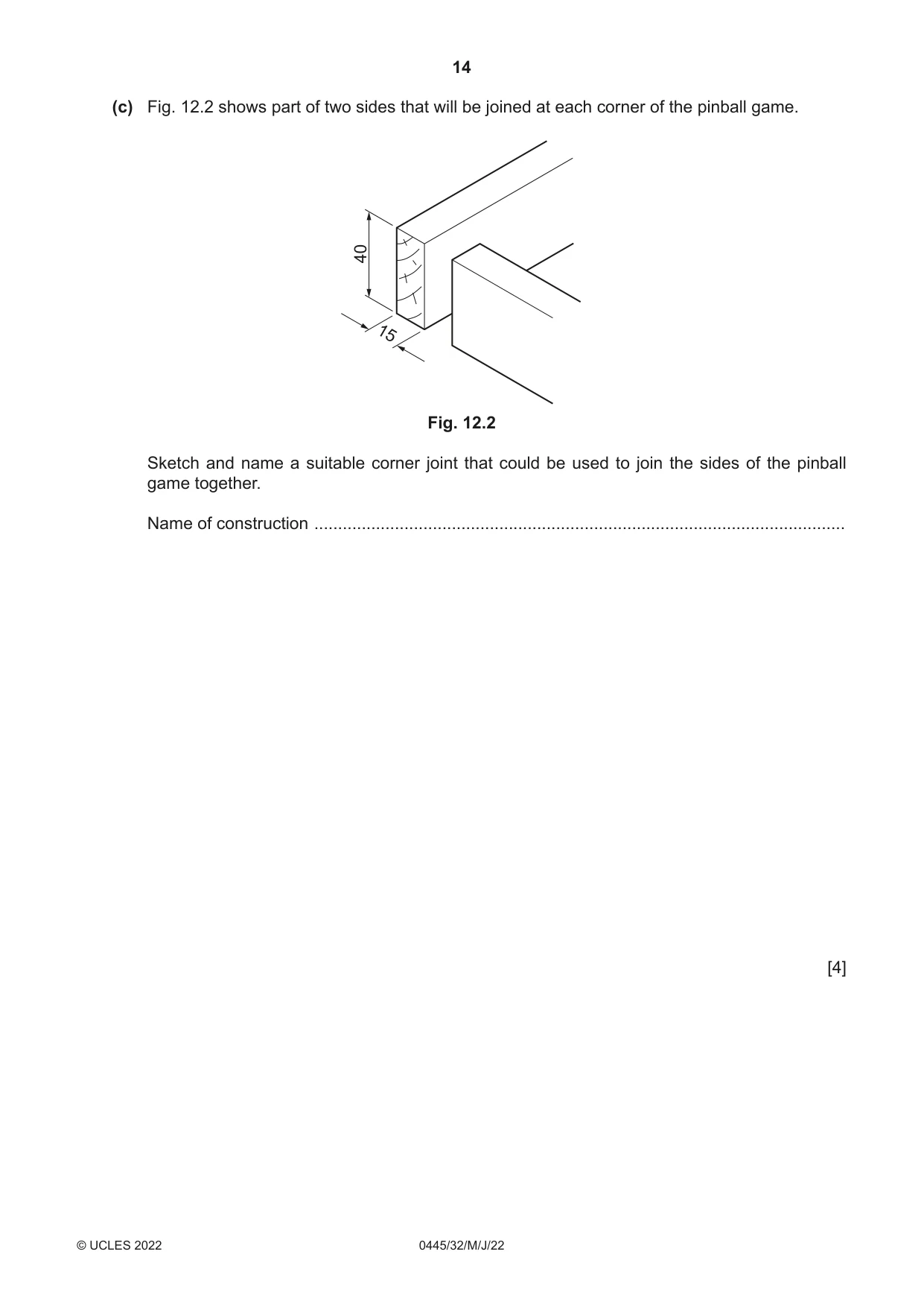
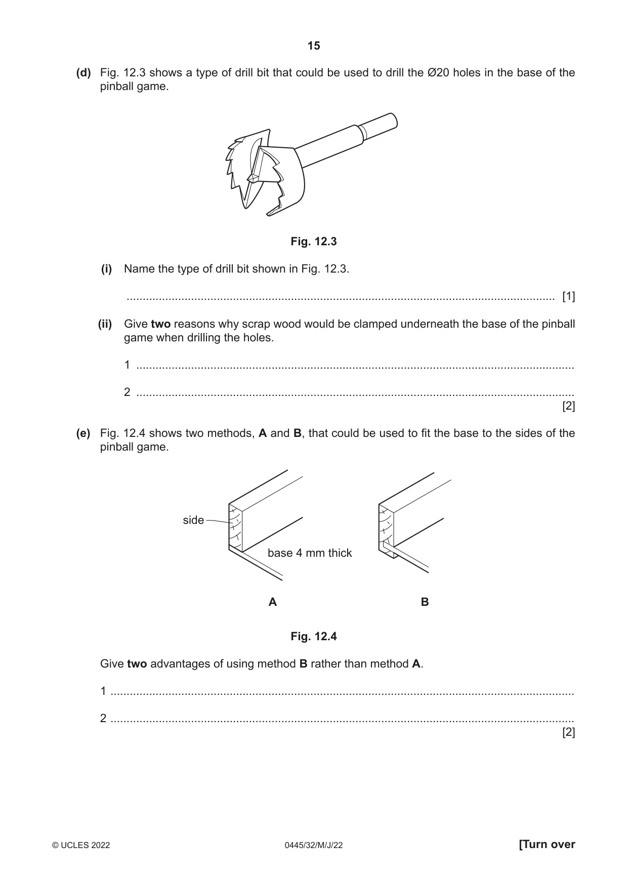
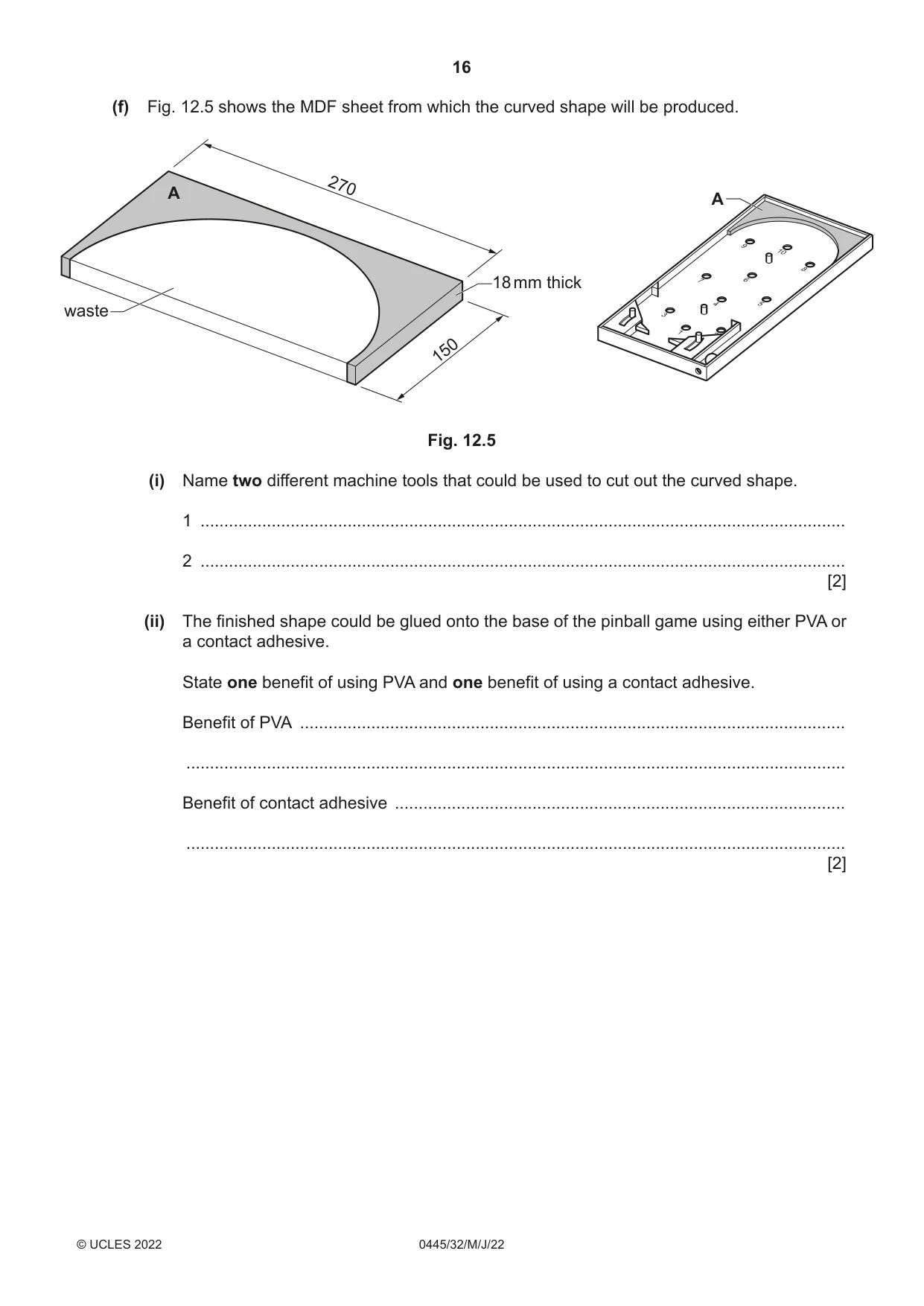
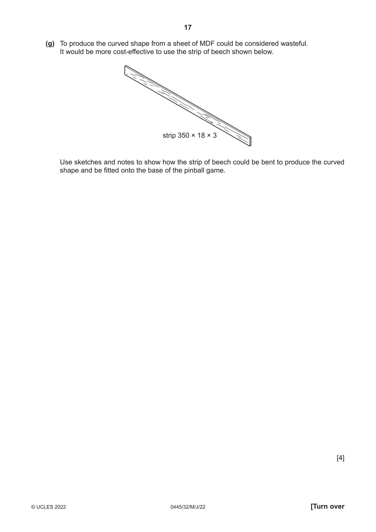
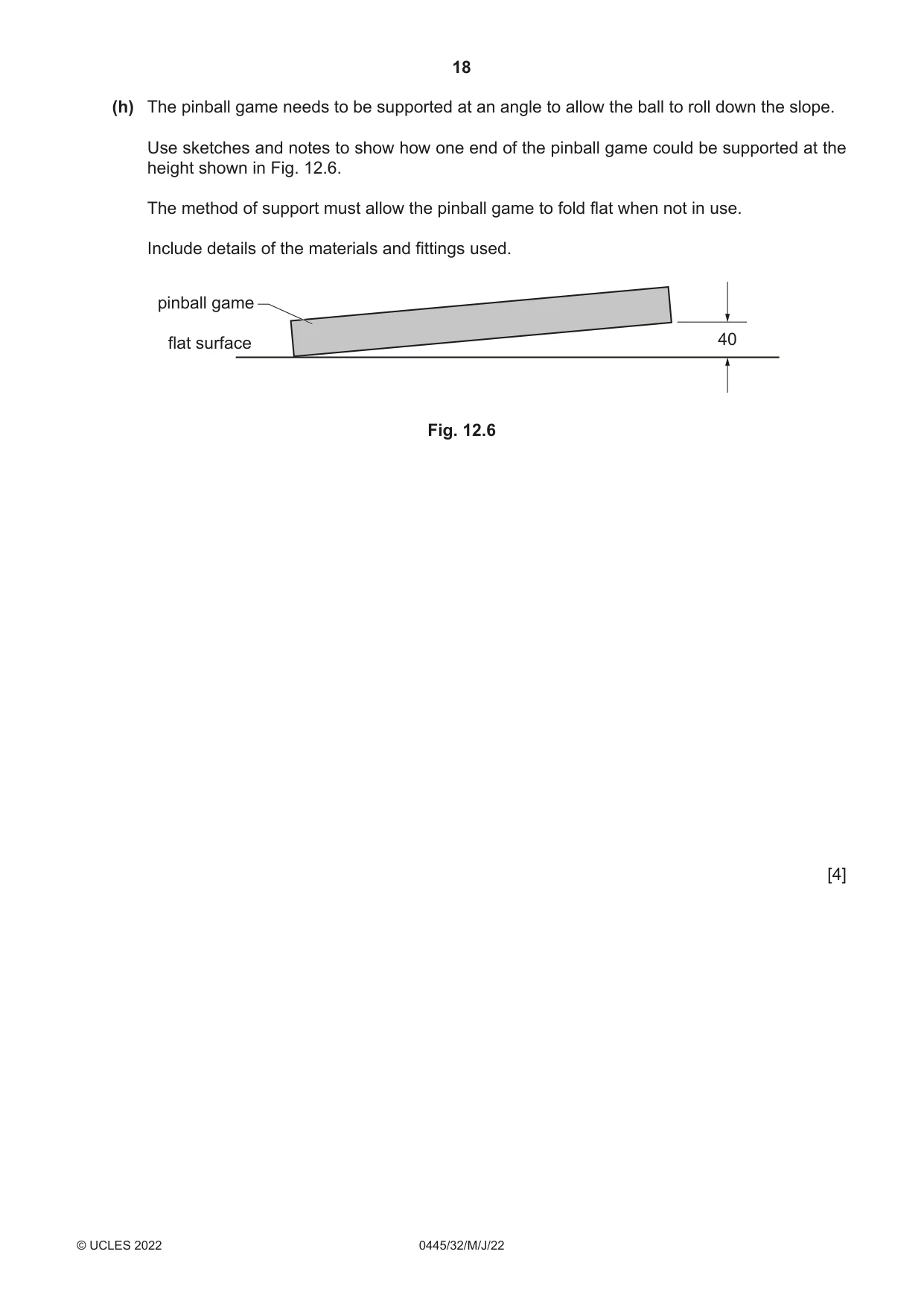
12 Fig. 12.1 shows an incomplete design for a pinball game. A 15 mm thick side base 9 10 8 7 6 4 5 40 3 600 1 2 300 Fig. 12.1 (a) The sides of the pinball game are made from beech. Give two properties of beech that make it suitable for the pinball game. 1 ................................................................................................................................................ 2 ................................................................................................................................................ [2] (b) State two ways in which the designer would need to consider safety when designing the pinball game. 1 ................................................................................................................................................ 2 ................................................................................................................................................ [2] (c) Fig. 12.2 shows part of two sides that will be joined at each corner of the pinball game. 40 15 Fig. 12.2 Sketch and name a suitable corner joint that could be used to join the sides of the pinball game together. Name of construction ................................................................................................................ [4] (d) Fig. 12.3 shows a type of drill bit that could be used to drill the Ø20 holes in the base of the pinball game. Fig. 12.3 (i) Name the type of drill bit shown in Fig. 12.3. ..................................................................................................................................... [1] (ii) Give two reasons why scrap wood would be clamped underneath the base of the pinball game when drilling the holes. 1 ........................................................................................................................................ 2 ........................................................................................................................................ [2] (e) Fig. 12.4 shows two methods, A and B, that could be used to fit the base to the sides of the pinball game. side base 4 mm thick A B Fig. 12.4 Give two advantages of using method B rather than method A. 1 ................................................................................................................................................ 2 ................................................................................................................................................ [2] (f) Fig. 12.5 shows the MDF sheet from which the curved shape will be produced. A 270 A 18 mm thick waste 150 Fig. 12.5 (i) Name two different machine tools that could be used to cut out the curved shape. 1 ........................................................................................................................................ 2 ........................................................................................................................................ [2] (ii) The finished shape could be glued onto the base of the pinball game using either PVA or a contact adhesive. State one benefit of using PVA and one benefit of using a contact adhesive. Benefit of PVA ................................................................................................................... ........................................................................................................................................... Benefit of contact adhesive ............................................................................................... ........................................................................................................................................... [2] (g) To produce the curved shape from a sheet of MDF could be considered wasteful. It would be more cost-effective to use the strip of beech shown below. strip 350 × 18 × 3 Use sketches and notes to show how the strip of beech could be bent to produce the curved shape and be fitted onto the base of the pinball game. [4] (h) The pinball game needs to be supported at an angle to allow the ball to roll down the slope. Use sketches and notes to show how one end of the pinball game could be supported at the height shown in Fig. 12.6. The method of support must allow the pinball game to fold flat when not in use. Include details of the materials and fittings used. pinball game flat surface 40 Fig. 12.6 [4]
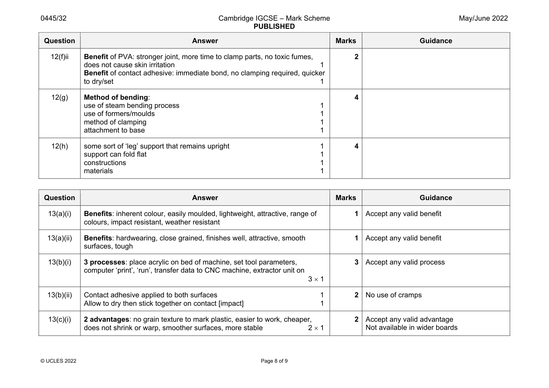
Mark scheme: 12(a) 2 properties: hardwearing, close-grained, finishes well, high impact resistant, attractive, tough 2 1 2 Accept any valid property Durable must be qualified 12(b) 2 safety considerations: no sharp edges, fingers should not be trapped, risk of ball flying out, cover to prevent ball flying out, ball large enough to prevent choking hazard 2 1 2 Accept any valid consideration 12(c) Variety of acceptable corner constructions: butt, rebate, lap joint, mitre, dovetail, finger [comb] joint, dowel Named 1 Technical accuracy/proportion of sketched construction 0–3 4 Award maximum 2/3 for butt joint Dowel joint: maximum number of dowels 2 12(d)(i) Saw tooth bit, forstner bit 1 Not hole saw 12(d)(ii) 2 reasons: prevent damage to work surface, prevents splitting of wood as drill cuts through, cleaner cut hole, protect drill table 2 1 2 Focus on the use of scrap wood, not clamping Not provide stability, not prevent wood flying off 12(e) 2 advantages: less likely to be pulled off sides [stronger], edges not visible [more attractive], gluing not required, more secure, lasts longer 2 1 2 Not greater surface area 12(f)(i) Router, scroll saw, band saw, jig saw, laser cutter, CNC milling machine 2 1 2 Question Answer Marks Guidance 12(f)ii Benefit of PVA: stronger joint, more time to clamp parts, no toxic fumes, does not cause skin irritation 1 Benefit of contact adhesive: immediate bond, no clamping required, quicker to dry/set 1 2 12(g) Method of bending: use of steam bending process 1 use of formers/moulds 1 method of clamping 1 attachment to base 1 4 12(h) some sort of ‘leg’ support that remains upright 1 support can fold flat 1 constructions 1 materials 1 4
Q13 · An incomplete design for a child’s toy lorry that could be made in a school workshop
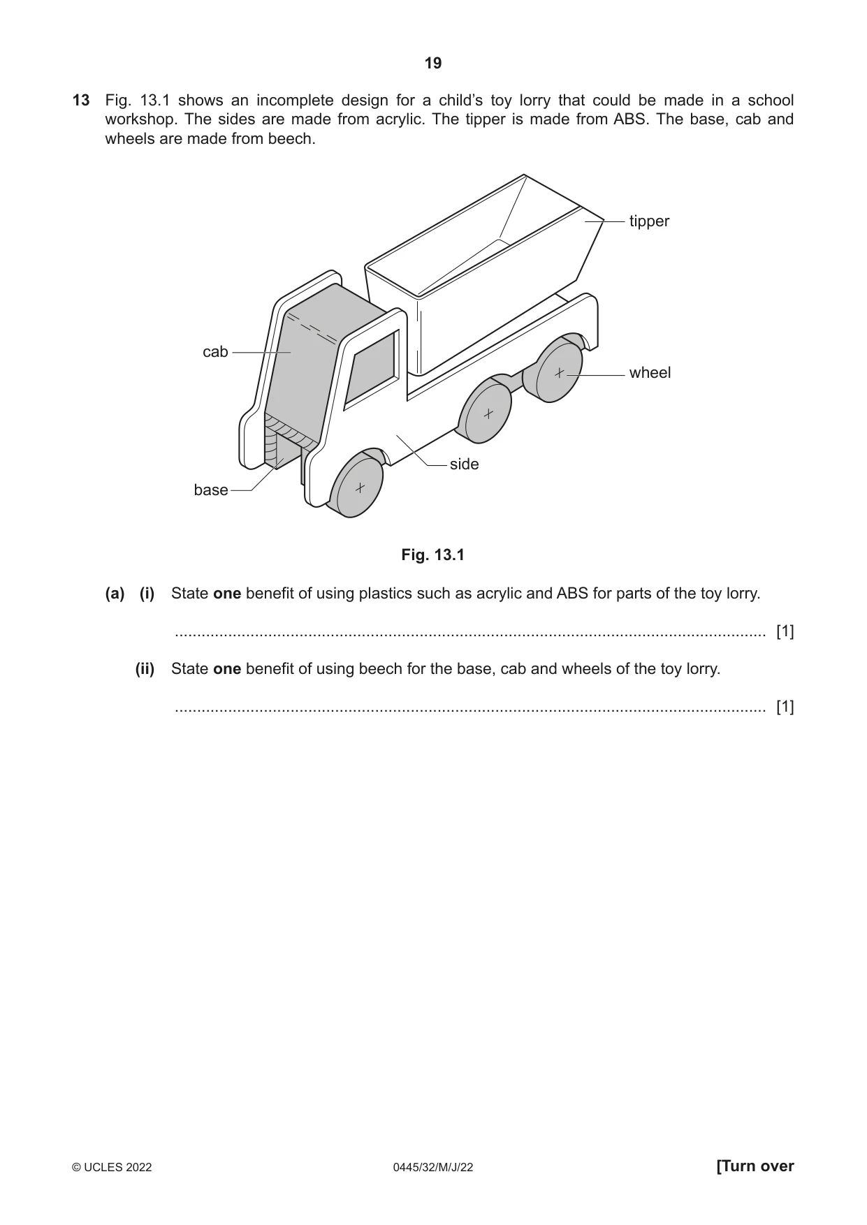
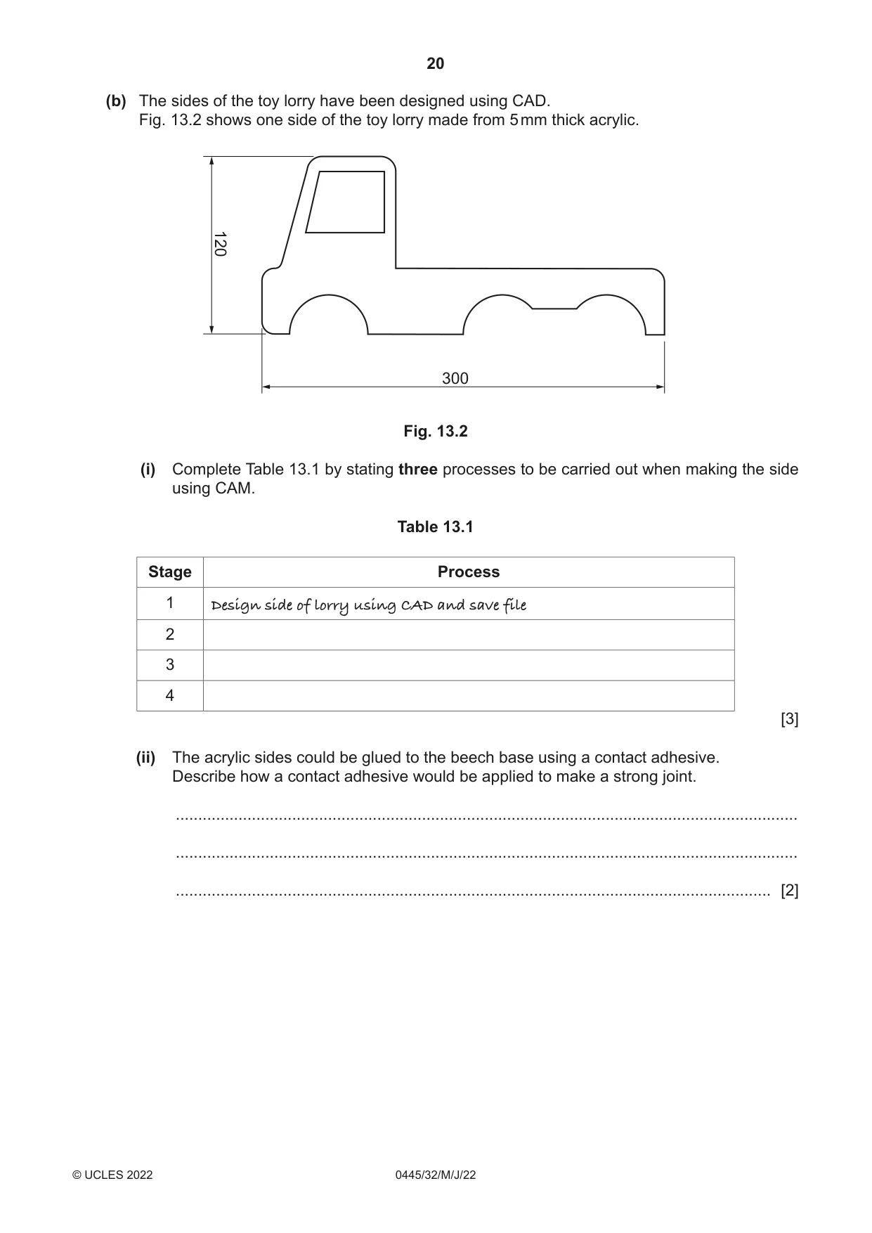
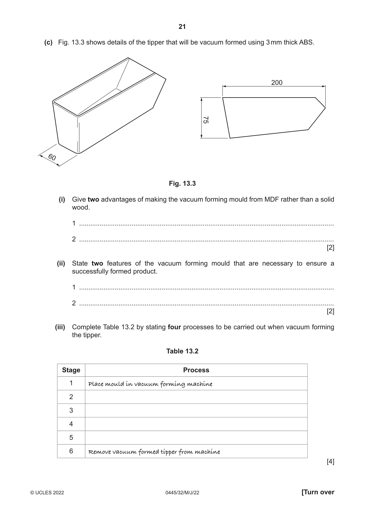
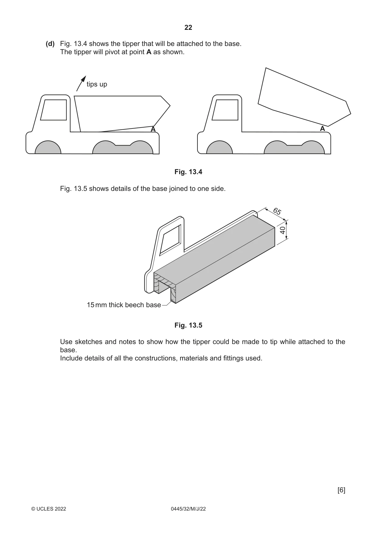
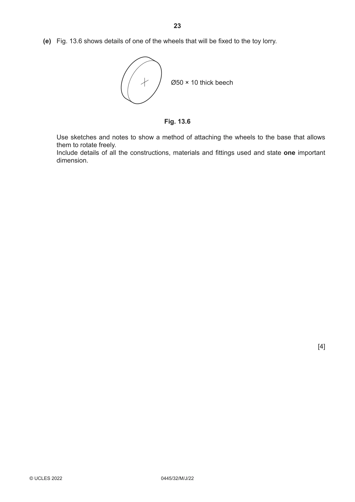
13 Fig. 13.1 shows an incomplete design for a child’s toy lorry that could be made in a school workshop. The sides are made from acrylic. The tipper is made from ABS. The base, cab and wheels are made from beech. tipper cab wheel side base Fig. 13.1 (a) (i) State one benefit of using plastics such as acrylic and ABS for parts of the toy lorry. ..................................................................................................................................... [1] (ii) State one benefit of using beech for the base, cab and wheels of the toy lorry. ..................................................................................................................................... [1] (b) The sides of the toy lorry have been designed using CAD. Fig. 13.2 shows one side of the toy lorry made from 5 mm thick acrylic. 120 300 Fig. 13.2 (i) Complete Table 13.1 by stating three processes to be carried out when making the side using CAM. Table 13.1 Stage Process 1 Design side of lorry using CAD and save file 2 3 4 [3] (ii) The acrylic sides could be glued to the beech base using a contact adhesive. Describe how a contact adhesive would be applied to make a strong joint. ........................................................................................................................................... ........................................................................................................................................... ..................................................................................................................................... [2] (c) Fig. 13.3 shows details of the tipper that will be vacuum formed using 3 mm thick ABS. 200 75 60 Fig. 13.3 (i) Give two advantages of making the vacuum forming mould from MDF rather than a solid wood. 1 ........................................................................................................................................ 2 ........................................................................................................................................ [2] (ii) State two features of the vacuum forming mould that are necessary to ensure a successfully formed product. 1 ........................................................................................................................................ 2 ........................................................................................................................................ [2] (iii) Complete Table 13.2 by stating four processes to be carried out when vacuum forming the tipper. Table 13.2 Stage Process 1 Place mould in vacuum forming machine 2 3 4 5 6 Remove vacuum formed tipper from machine [4]
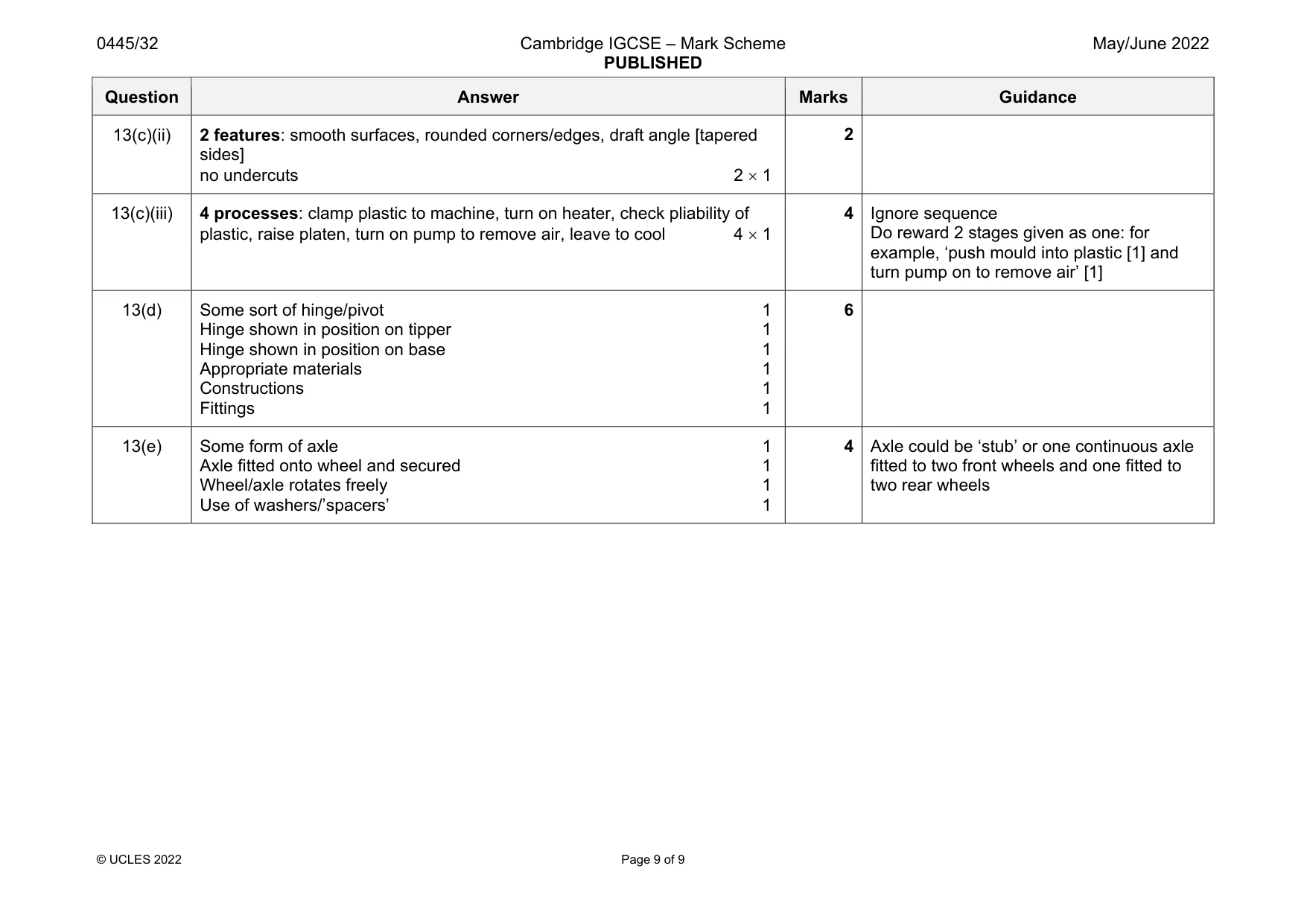
Mark scheme: 13(a)(i) Benefits: inherent colour, easily moulded, lightweight, attractive, range of colours, impact resistant, weather resistant 1 Accept any valid benefit 13(a)(ii) Benefits: hardwearing, close grained, finishes well, attractive, smooth surfaces, tough 1 Accept any valid benefit 13(b)(i) 3 processes: place acrylic on bed of machine, set tool parameters, computer ‘print’, ‘run’, transfer data to CNC machine, extractor unit on 3 1 3 Accept any valid process 13(b)(ii) Contact adhesive applied to both surfaces 1 Allow to dry then stick together on contact [impact] 1 2 No use of cramps 13(c)(i) 2 advantages: no grain texture to mark plastic, easier to work, cheaper, does not shrink or warp, smoother surfaces, more stable 2 1 2 Accept any valid advantage Not available in wider boards Question Answer Marks Guidance 13(c)(ii) 2 features: smooth surfaces, rounded corners/edges, draft angle [tapered sides] no undercuts 2 1 2 13(c)(iii) 4 processes: clamp plastic to machine, turn on heater, check pliability of plastic, raise platen, turn on pump to remove air, leave to cool 4 1 4 Ignore sequence Do reward 2 stages given as one: for example, ‘push mould into plastic [1] and turn pump on to remove air’ [1] 13(d) Some sort of hinge/pivot 1 Hinge shown in position on tipper 1 Hinge shown in position on base 1 Appropriate materials 1 Constructions 1 Fittings 1 6 13(e) Some form of axle 1 Axle fitted onto wheel and secured 1 Wheel/axle rotates freely 1 Use of washers/’spacers’ 1 4 Axle could be ‘stub’ or one continuous axle fitted to two front wheels and one fitted to two rear wheels
What was in this paper
The subtopics covered by these 13 questions, and how many questions each got. Open one in a new tab to see every Cambridge question on it.
What you needed in this session
Cambridge’s own grade thresholds for 2022 May/June, Paper 3 · Variant 2. A higher threshold means an easier paper — the bar moves with how the cohort did.