Cambridge IGCSE Design and Technology 0445 — 2023 May/June Paper 3 · Variant 1
0445/31/M/J/23 · 13 questions · 50 marks · ≈56 min
The question paper and its mark scheme, free to read here and free to download. This is Cambridge’s own paper, exactly as it was sat.
Question paper20 pages
Mark scheme9 pages
Answers below. Sit the paper first if you are practising.
Questions as text
Question 1
1 Fig. 1.1 shows a cordless drill. Fig. 1.1 Identify three ergonomic features of the cordless drill. 1 ....................................................................................................................................................... 2 ....................................................................................................................................................... 3 ....................................................................................................................................................... [3]
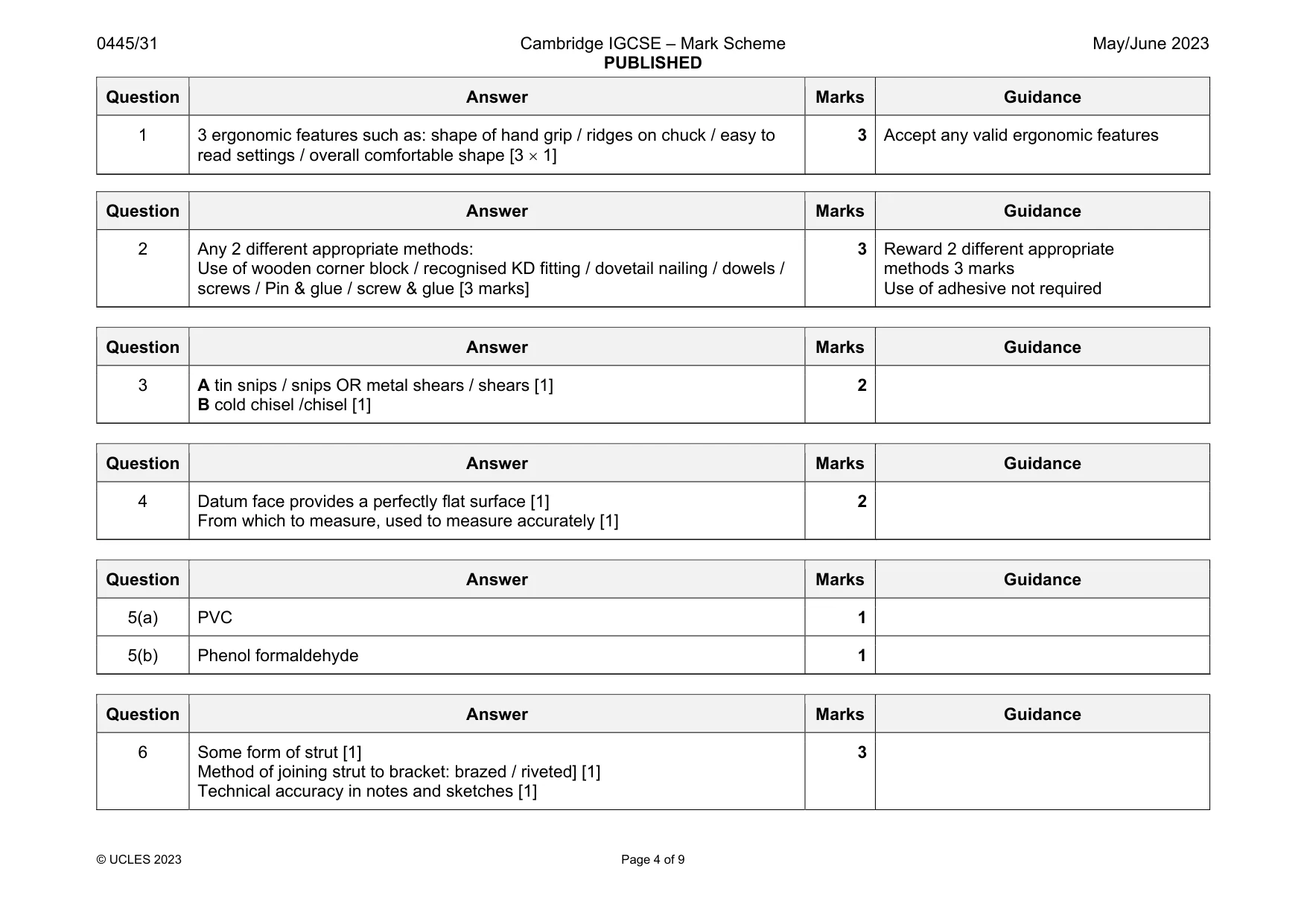
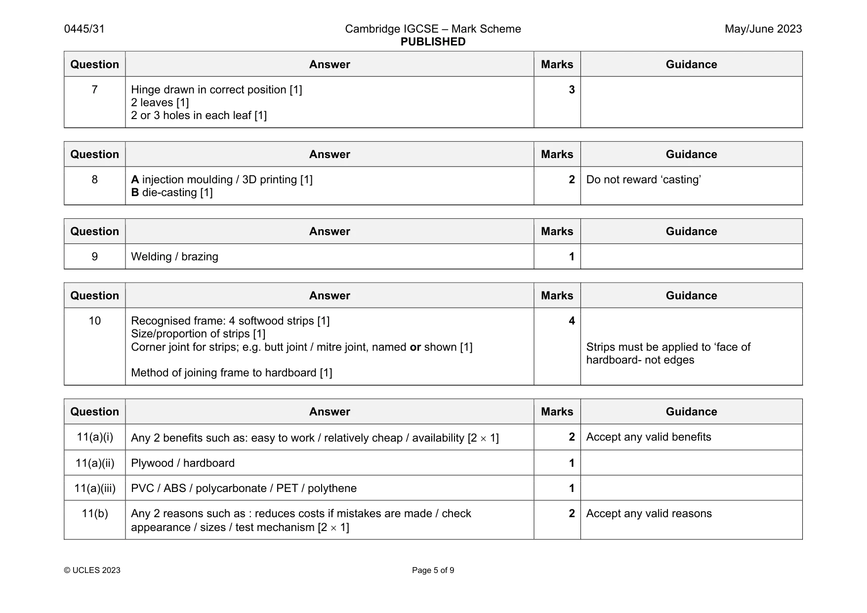
Mark scheme: 1 3 ergonomic features such as: shape of hand grip / ridges on chuck / easy to read settings / overall comfortable shape [3 1] 3 Accept any valid ergonomic features
Q2 · Views of a butt joint using softwood 60 mm wide × 15 mm thick
2 Fig. 2.1 shows views of a butt joint using softwood 60 mm wide × 15 mm thick. Fig. 2.1 Add sketches and notes to Fig. 2.1 to show how the butt joint could be strengthened. [3]
Mark scheme: 2 Any 2 different appropriate methods: Use of wooden corner block / recognised KD fitting / dovetail nailing / dowels / screws / Pin & glue / screw & glue [3 marks] 3 Reward 2 different appropriate methods 3 marks Use of adhesive not required
Q3 · Two tools, A and B, that can be used to cut sheet metal
3 Fig. 3.1 shows two tools, A and B, that can be used to cut sheet metal. A B Fig. 3.1 Give the name of the tools labelled A and B in Fig. 3.1. A ....................................................................................................................................................... B ....................................................................................................................................................... [2]
Mark scheme: 3 A tin snips / snips OR metal shears / shears [1] B cold chisel /chisel [1] 2
Q4 · A hardwood block with a line measured and marked out 100 mm from the datum face
4 Fig. 4.1 shows a hardwood block with a line measured and marked out 100 mm from the datum face. 100 datum face Fig. 4.1 Describe the purpose of the datum face. .......................................................................................................................................................... .................................................................................................................................................... [2]
Mark scheme: 4 Datum face provides a perfectly flat surface [1] From which to measure, used to measure accurately [1] 2
Q5 · Select the plastic from the list below that corresponds to the description
5 Select the plastic from the list below that corresponds to the description. expanded polystyrene PVC nylon polyester resin phenol formaldehyde (a) Good chemical and weather resistance, used for pipes, guttering and window frames. ............................................................................................................................................. [1] (b) Hard, brittle, heat resistant, used for dark electrical fittings, saucepan and kettle handles. ............................................................................................................................................. [1]
Mark scheme: 5(a) PVC 1 5(b) Phenol formaldehyde 1
Q6 · An incomplete design for a bracket made from 3 mm thick mild steel strip that will be…
6 Fig. 6.1 shows an incomplete design for a bracket made from 3 mm thick mild steel strip that will be fixed to a wall. weight is applied 150 25 Fig. 6.1 Use sketches and notes to show how the bracket could be strengthened. [3]
Mark scheme: 6 Some form of strut [1] Method of joining strut to bracket: brazed / riveted] [1] Technical accuracy in notes and sketches [1]
Q7 · A hardwood rail, 40 × 25, with a recess cut out, ready to take a butt hinge
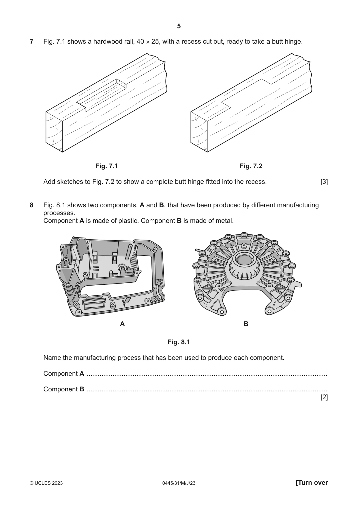
7 Fig. 7.1 shows a hardwood rail, 40 × 25, with a recess cut out, ready to take a butt hinge. Fig. 7.1 Fig. 7.2 Add sketches to Fig. 7.2 to show a complete butt hinge fitted into the recess. [3]
Mark scheme: 7 Hinge drawn in correct position [1] 2 leaves [1] 2 or 3 holes in each leaf [1] 3
Q8 · Two components, A and B, that have been produced by different manufacturing processes
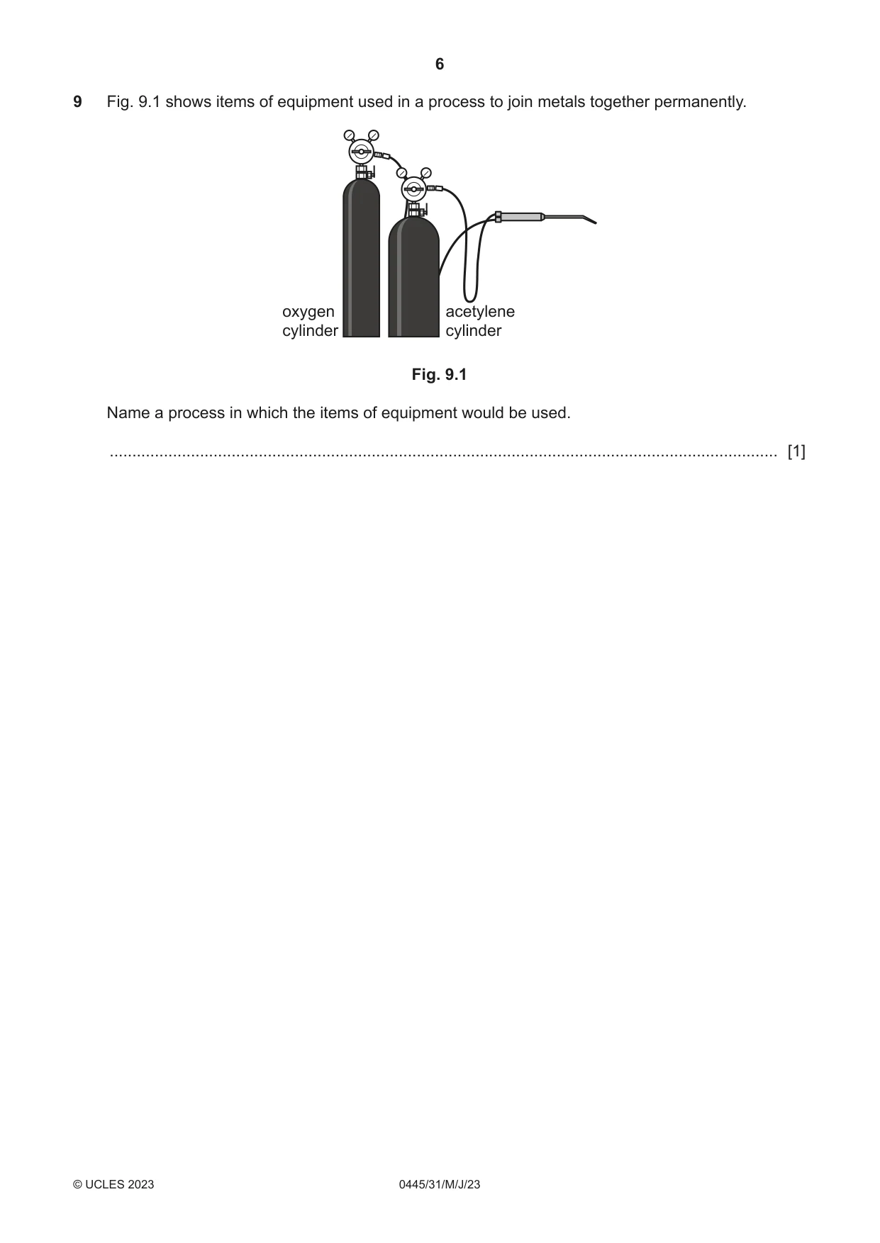
8 Fig. 8.1 shows two components, A and B, that have been produced by different manufacturing processes. Component A is made of plastic. Component B is made of metal. A B Fig. 8.1 Name the manufacturing process that has been used to produce each component. Component A ................................................................................................................................... Component B ................................................................................................................................... [2]
Mark scheme: 8 A injection moulding / 3D printing [1] B die-casting [1] 2 Do not reward ‘casting’
Q9 · Items of equipment used in a process to join metals together permanently
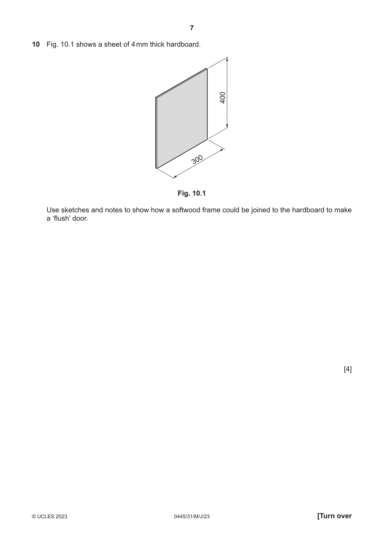
9 Fig. 9.1 shows items of equipment used in a process to join metals together permanently. oxygen acetylene cylinder cylinder Fig. 9.1 Name a process in which the items of equipment would be used. .................................................................................................................................................... [1]
Mark scheme: 9 Welding / brazing 1
Q10 · A sheet of 4 mm thick hardboard
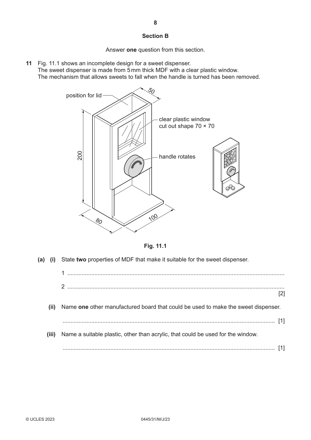
10 Fig. 10.1 shows a sheet of 4 mm thick hardboard. 400 300 Fig. 10.1 Use sketches and notes to show how a softwood frame could be joined to the hardboard to make a ‘flush’ door. [4]
Mark scheme: 10 Recognised frame: 4 softwood strips [1] Size/proportion of strips [1] Corner joint for strips; e.g. butt joint / mitre joint, named or shown [1] Method of joining frame to hardboard [1] Strips must be applied to ‘face of hardboard- not edges
Q11 · An incomplete design for a sweet dispenser
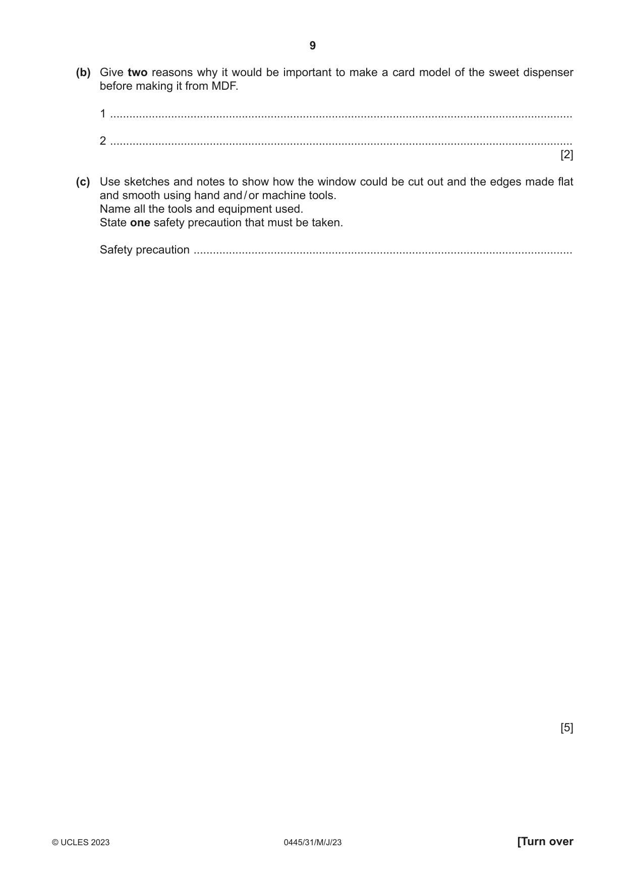
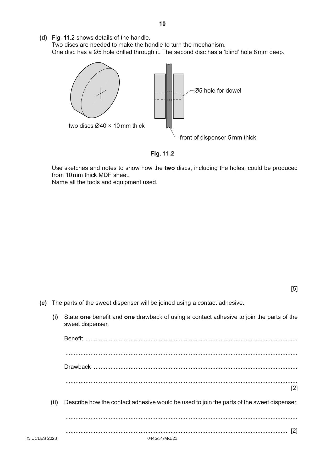
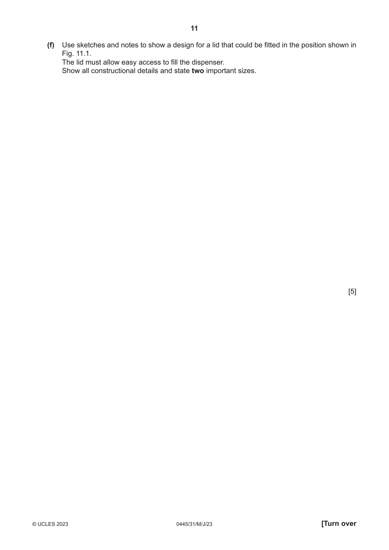
11 Fig. 11.1 shows an incomplete design for a sweet dispenser. The sweet dispenser is made from 5 mm thick MDF with a clear plastic window. The mechanism that allows sweets to fall when the handle is turned has been removed. 50 position for lid clear plastic window cut out shape 70 × 70 200 handle rotates 100 80 Fig. 11.1 (a) (i) State two properties of MDF that make it suitable for the sweet dispenser. 1 ........................................................................................................................................ 2 ........................................................................................................................................ [2] (ii) Name one other manufactured board that could be used to make the sweet dispenser. ..................................................................................................................................... [1] (iii) Name a suitable plastic, other than acrylic, that could be used for the window. ..................................................................................................................................... [1] (b) Give two reasons why it would be important to make a card model of the sweet dispenser before making it from MDF. 1 ................................................................................................................................................ 2 ................................................................................................................................................ [2] (c) Use sketches and notes to show how the window could be cut out and the edges made flat and smooth using hand and / or machine tools. Name all the tools and equipment used. State one safety precaution that must be taken. Safety precaution ...................................................................................................................... [5] (d) Fig. 11.2 shows details of the handle. Two discs are needed to make the handle to turn the mechanism. One disc has a Ø5 hole drilled through it. The second disc has a ‘blind’ hole 8 mm deep. Ø5 hole for dowel two discs Ø40 × 10 mm thick front of dispenser 5 mm thick Fig. 11.2 Use sketches and notes to show how the two discs, including the holes, could be produced from 10 mm thick MDF sheet. Name all the tools and equipment used. [5] (e) The parts of the sweet dispenser will be joined using a contact adhesive. (i) State one benefit and one drawback of using a contact adhesive to join the parts of the sweet dispenser. Benefit ............................................................................................................................... ........................................................................................................................................... Drawback .......................................................................................................................... ........................................................................................................................................... [2] (ii) Describe how the contact adhesive would be used to join the parts of the sweet dispenser. ........................................................................................................................................... ..................................................................................................................................... [2] (f) Use sketches and notes to show a design for a lid that could be fitted in the position shown in Fig. 11.1. The lid must allow easy access to fill the dispenser. Show all constructional details and state two important sizes. [5]
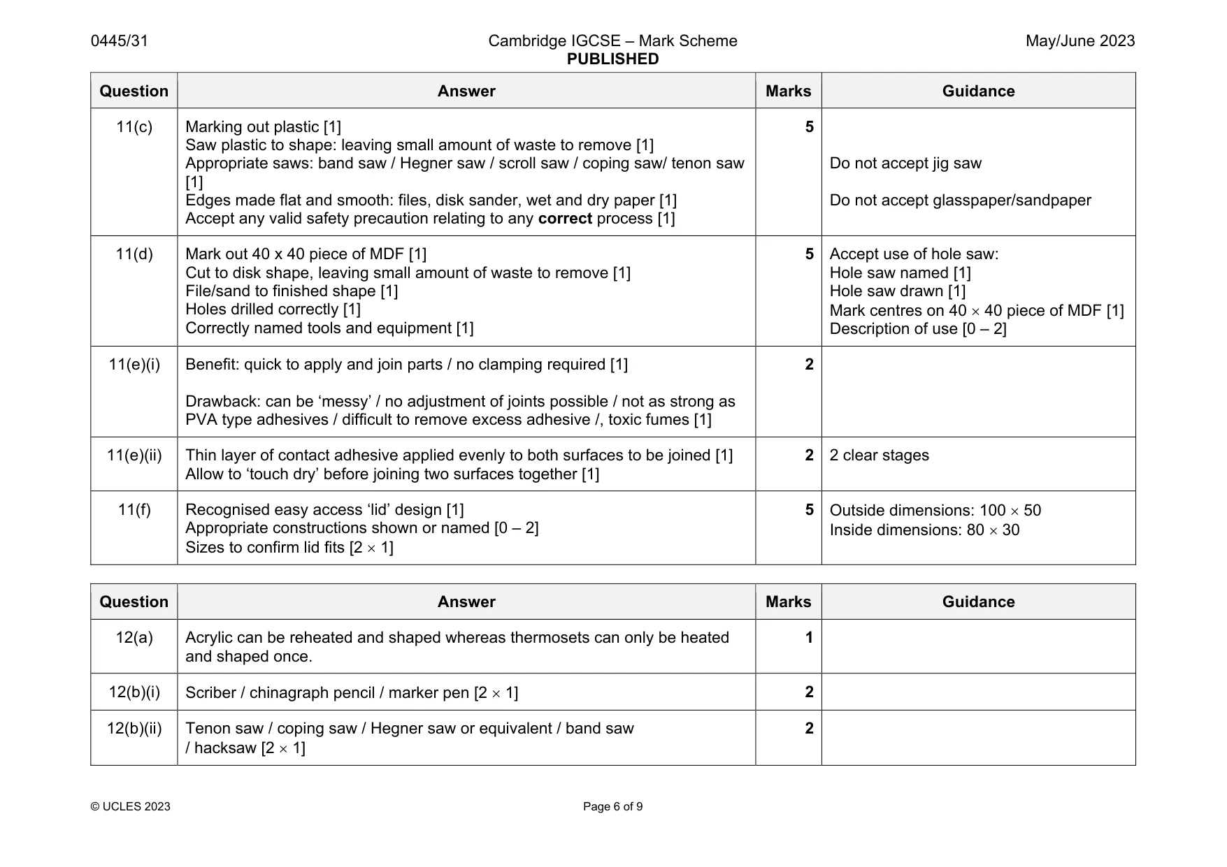
Mark scheme: 11(a)(i) 2 Accept any valid benefits 11(a)(ii) Plywood / hardboard 1 11(a)(iii) PVC / ABS / polycarbonate / PET / polythene 1 11(b) Any 2 reasons such as : reduces costs if mistakes are made / check appearance / sizes / test mechanism [2 1] 2 Accept any valid reasons Question Answer Marks Guidance 11(c) Marking out plastic [1] Saw plastic to shape: leaving small amount of waste to remove [1] Appropriate saws: band saw / Hegner saw / scroll saw / coping saw/ tenon saw [1] Edges made flat and smooth: files, disk sander, wet and dry paper [1] Accept any valid safety precaution relating to any correct process [1] 5 Do not accept jig saw Do not accept glasspaper/sandpaper 11(d) Mark out 40 x 40 piece of MDF [1] Cut to disk shape, leaving small amount of waste to remove [1] File/sand to finished shape [1] Holes drilled correctly [1] Correctly named tools and equipment [1] 5 Accept use of hole saw: Hole saw named [1] Hole saw drawn [1] Mark centres on 40 40 piece of MDF [1] Description of use [0 – 2] 11(e)(i) Benefit: quick to apply and join parts / no clamping required [1] Drawback: can be ‘messy’ / no adjustment of joints possible / not as strong as PVA type adhesives / difficult to remove excess adhesive /, toxic fumes [1] 2 11(e)(ii) Thin layer of contact adhesive applied evenly to both surfaces to be joined [1] Allow to ‘touch dry’ before joining two surfaces together [1] 2 2 clear stages 11(f) Recognised easy access ‘lid’ design [1] Appropriate constructions shown or named [0 – 2] Sizes to confirm lid fits [2 1] 5 Outside dimensions: 100 50 Inside dimensions: 80 30
Q12 · An incomplete design for an adjustable stand to support a tablet
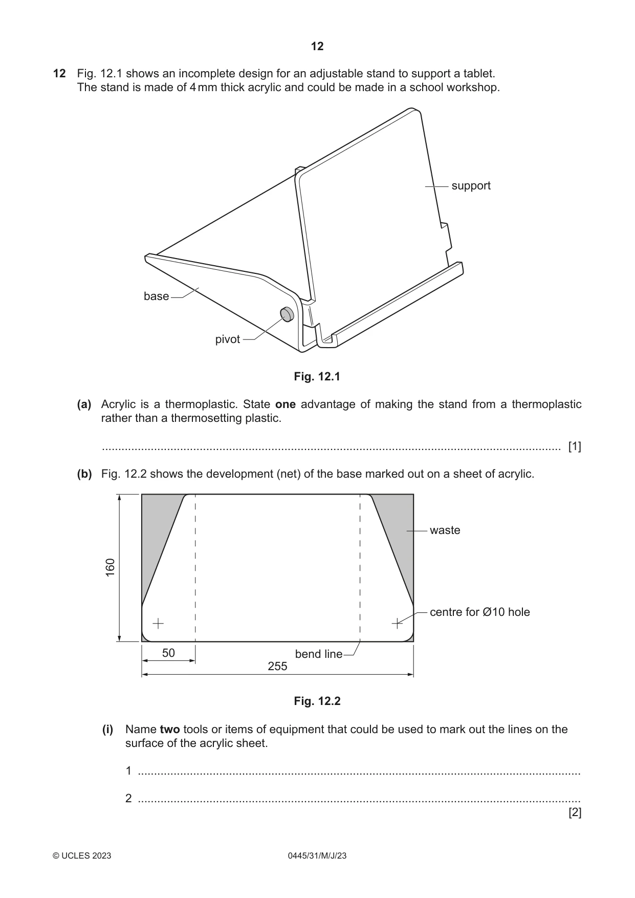
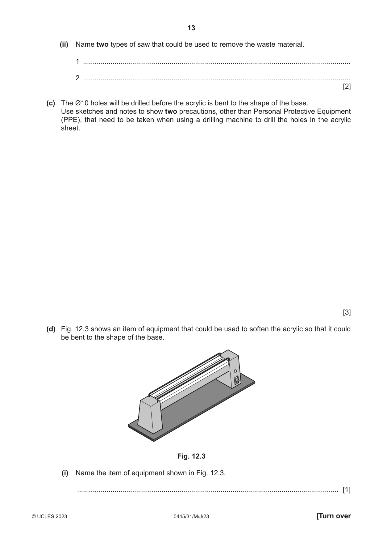
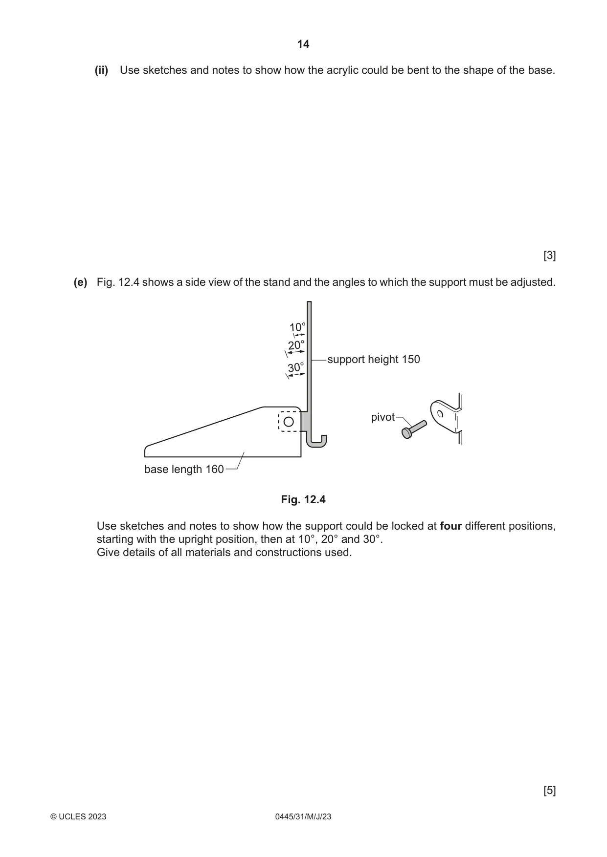
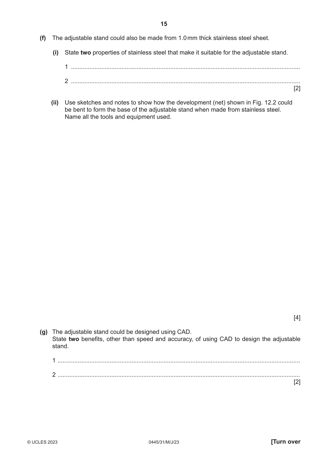
12 Fig. 12.1 shows an incomplete design for an adjustable stand to support a tablet. The stand is made of 4 mm thick acrylic and could be made in a school workshop. support base pivot Fig. 12.1 (a) Acrylic is a thermoplastic. State one advantage of making the stand from a thermoplastic rather than a thermosetting plastic. ............................................................................................................................................. [1] (b) Fig. 12.2 shows the development (net) of the base marked out on a sheet of acrylic. waste 160 centre for Ø10 hole 50 bend line 255 Fig. 12.2 (i) Name two tools or items of equipment that could be used to mark out the lines on the surface of the acrylic sheet. 1 ........................................................................................................................................ 2 ........................................................................................................................................ [2] (ii) Name two types of saw that could be used to remove the waste material. 1 ........................................................................................................................................ 2 ........................................................................................................................................ [2] (c) The Ø10 holes will be drilled before the acrylic is bent to the shape of the base. Use sketches and notes to show two precautions, other than Personal Protective Equipment (PPE), that need to be taken when using a drilling machine to drill the holes in the acrylic sheet. [3] (d) Fig. 12.3 shows an item of equipment that could be used to soften the acrylic so that it could be bent to the shape of the base. Fig. 12.3 (i) Name the item of equipment shown in Fig. 12.3. ..................................................................................................................................... [1] (ii) Use sketches and notes to show how the acrylic could be bent to the shape of the base. [3] (e) Fig. 12.4 shows a side view of the stand and the angles to which the support must be adjusted. 10° 20° support height 150 30° pivot base length 160 Fig. 12.4 Use sketches and notes to show how the support could be locked at four different positions, starting with the upright position, then at 10°, 20° and 30°. Give details of all materials and constructions used. [5] (f) The adjustable stand could also be made from 1.0 mm thick stainless steel sheet. (i) State two properties of stainless steel that make it suitable for the adjustable stand. 1 ........................................................................................................................................ 2 ........................................................................................................................................ [2] (ii) Use sketches and notes to show how the development (net) shown in Fig. 12.2 could be bent to form the base of the adjustable stand when made from stainless steel. Name all the tools and equipment used. [4] (g) The adjustable stand could be designed using CAD. State two benefits, other than speed and accuracy, of using CAD to design the adjustable stand. 1 ................................................................................................................................................ 2 ................................................................................................................................................ [2]
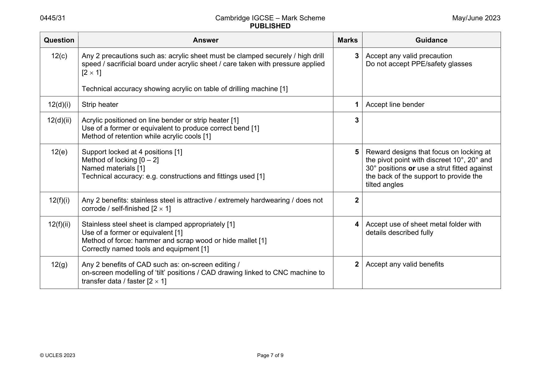
Mark scheme: 12(a) Acrylic can be reheated and shaped whereas thermosets can only be heated and shaped once. 1 12(b)(i) Scriber / chinagraph pencil / marker pen [2 1] 2 12(b)(ii) Tenon saw / coping saw / Hegner saw or equivalent / band saw / hacksaw [2 1] 2 Question Answer Marks Guidance 12(c) Any 2 precautions such as: acrylic sheet must be clamped securely / high drill speed / sacrificial board under acrylic sheet / care taken with pressure applied [2 1] Technical accuracy showing acrylic on table of drilling machine [1] 3 Accept any valid precaution Do not accept PPE/safety glasses 12(d)(i) Strip heater 1 Accept line bender 12(d)(ii) Acrylic positioned on line bender or strip heater [1] Use of a former or equivalent to produce correct bend [1] Method of retention while acrylic cools [1] 3 12(e) Support locked at 4 positions [1] Method of locking [0 – 2] Named materials [1] Technical accuracy: e.g. constructions and fittings used [1] 5 Reward designs that focus on locking at the pivot point with discreet 10°, 20° and 30° positions or use a strut fitted against the back of the support to provide the tilted angles 12(f)(i) Any 2 benefits: stainless steel is attractive / extremely hardwearing / does not corrode / self-finished [2 1] 2 12(f)(ii) Stainless steel sheet is clamped appropriately [1] Use of a former or equivalent [1] Method of force: hammer and scrap wood or hide mallet [1] Correctly named tools and equipment [1] 4 Accept use of sheet metal folder with details described fully 12(g) Any 2 benefits of CAD such as: on-screen editing / on-screen modelling of ‘tilt’ positions / CAD drawing linked to CNC machine to transfer data / faster [2 1] 2 Accept any valid benefits
Q13 · A desk organiser made from hardwood
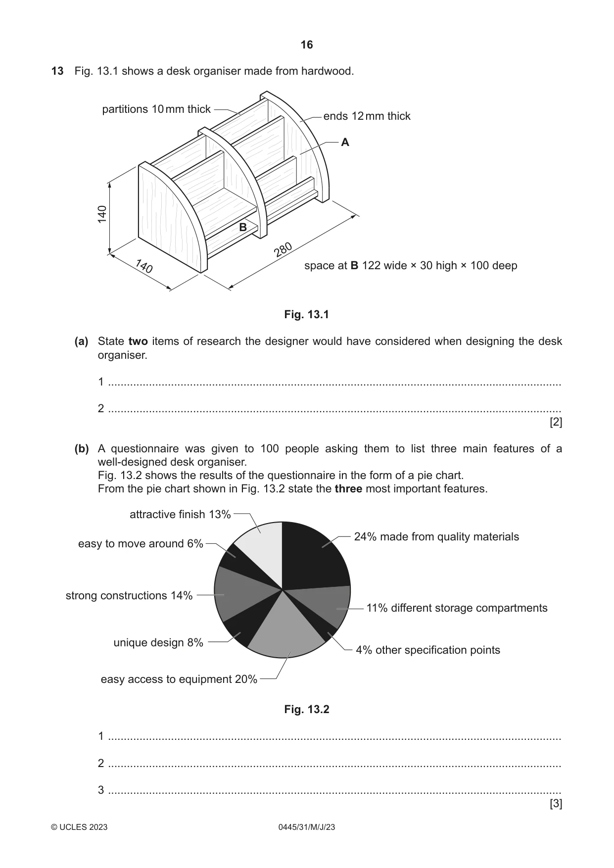
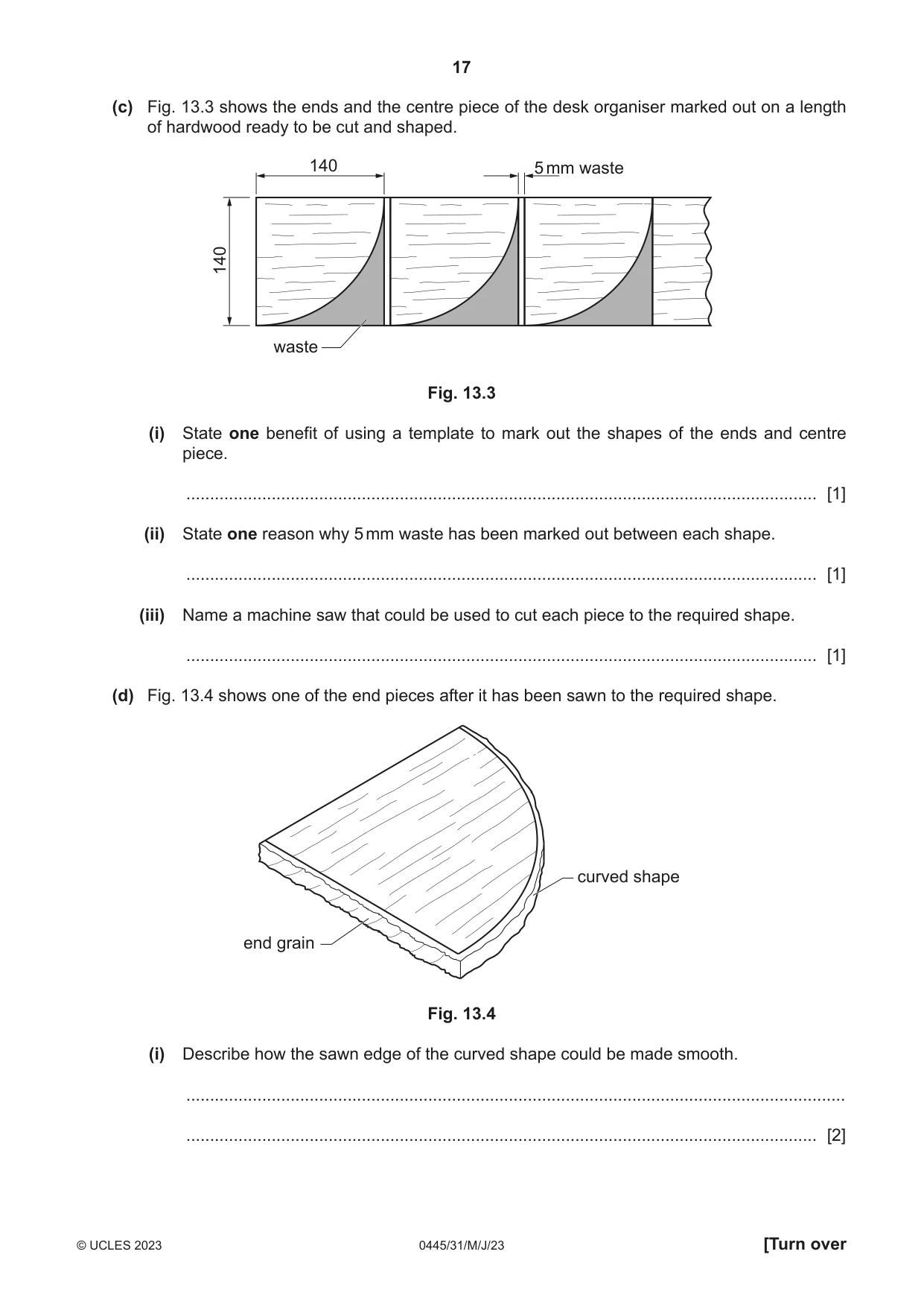
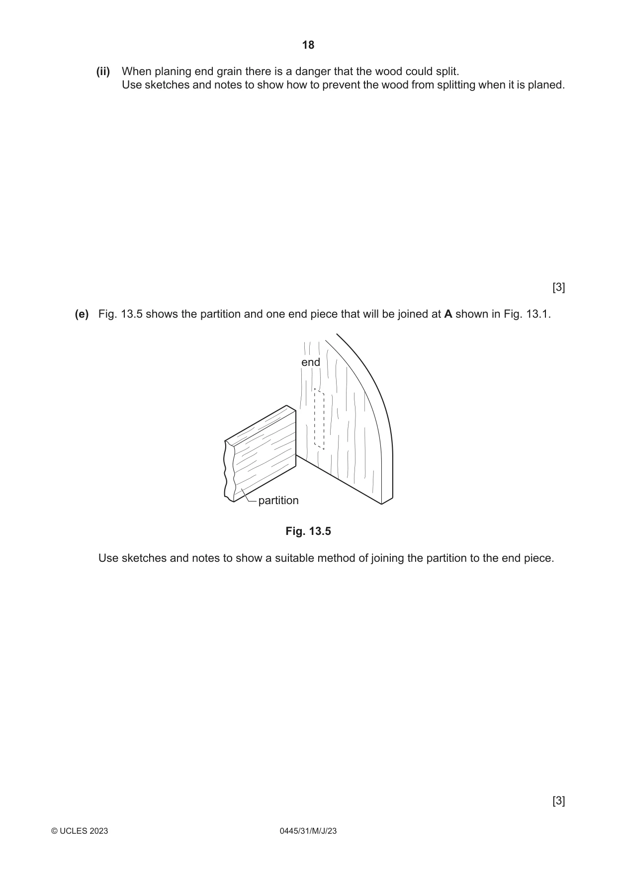
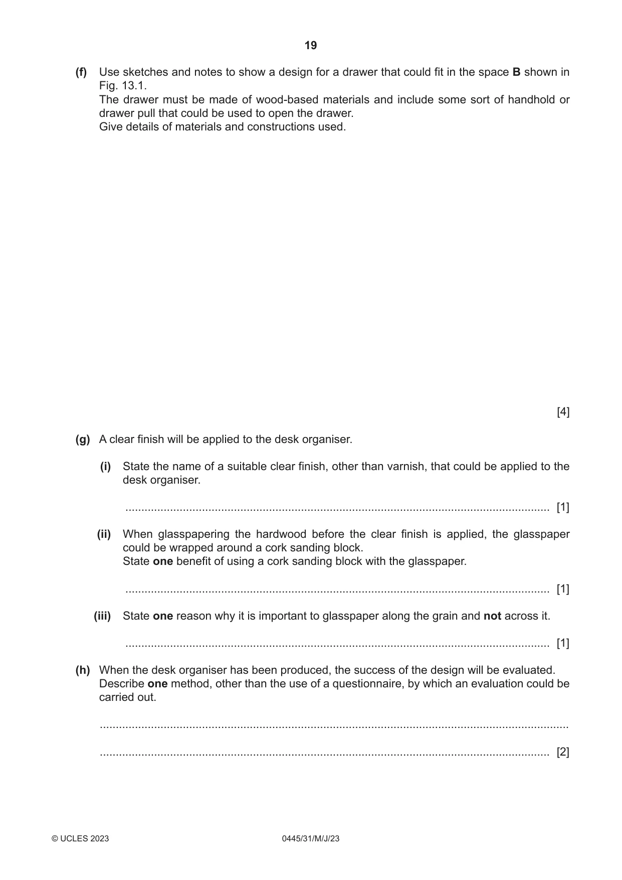
13 Fig. 13.1 shows a desk organiser made from hardwood. partitions 10 mm thick ends 12 mm thick A 140 B 280 space at B 122 wide × 30 high × 100 deep 140 Fig. 13.1 (a) State two items of research the designer would have considered when designing the desk organiser. 1 ................................................................................................................................................ 2 ................................................................................................................................................ [2] (b) A questionnaire was given to 100 people asking them to list three main features of a well-designed desk organiser. Fig. 13.2 shows the results of the questionnaire in the form of a pie chart. From the pie chart shown in Fig. 13.2 state the three most important features. attractive finish 13% 24% made from quality materials easy to move around 6% strong constructions 14% 11% different storage compartments unique design 8% 4% other specification points easy access to equipment 20% Fig. 13.2 1 ................................................................................................................................................ 2 ................................................................................................................................................ 3 ................................................................................................................................................ [3] (c) Fig. 13.3 shows the ends and the centre piece of the desk organiser marked out on a length of hardwood ready to be cut and shaped. 140 5 mm waste 140 waste Fig. 13.3 (i) State one benefit of using a template to mark out the shapes of the ends and centre piece. ..................................................................................................................................... [1] (ii) State one reason why 5 mm waste has been marked out between each shape. ..................................................................................................................................... [1] (iii) Name a machine saw that could be used to cut each piece to the required shape. ..................................................................................................................................... [1] (d) Fig. 13.4 shows one of the end pieces after it has been sawn to the required shape. curved shape end grain Fig. 13.4 (i) Describe how the sawn edge of the curved shape could be made smooth. ........................................................................................................................................... ..................................................................................................................................... [2] (ii) When planing end grain there is a danger that the wood could split. Use sketches and notes to show how to prevent the wood from splitting when it is planed. [3] (e) Fig. 13.5 shows the partition and one end piece that will be joined at A shown in Fig. 13.1. end partition Fig. 13.5 Use sketches and notes to show a suitable method of joining the partition to the end piece. [3]
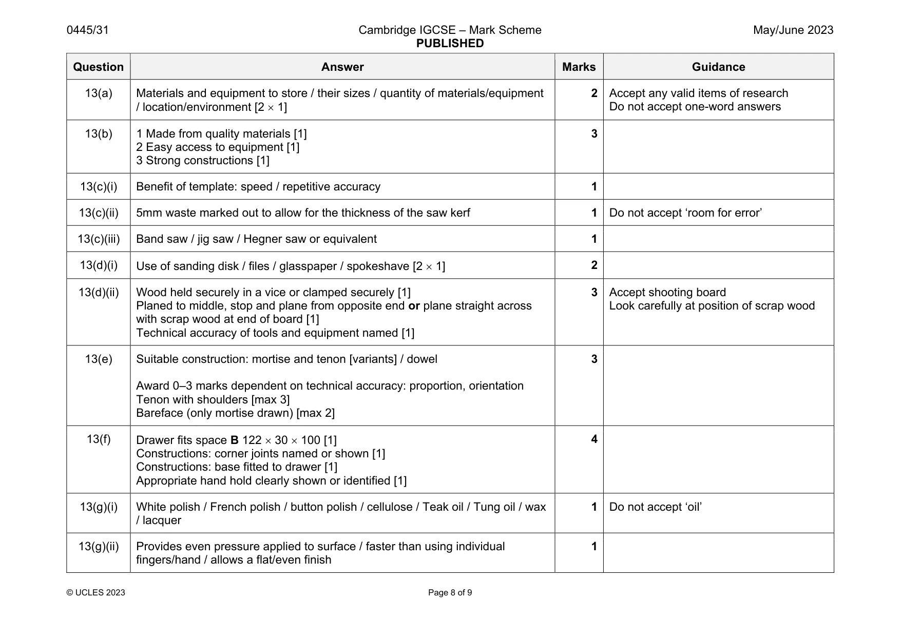
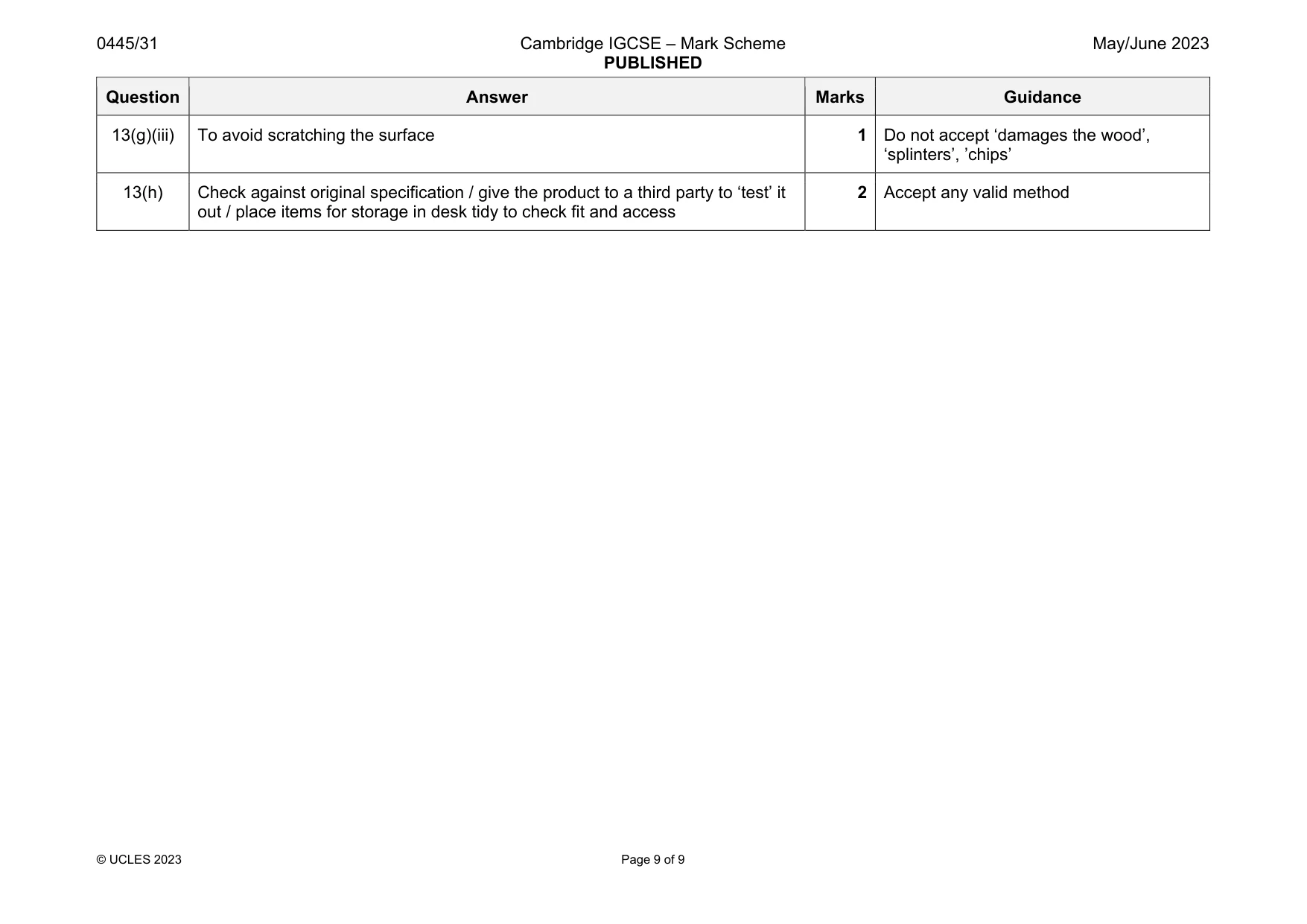
Mark scheme: 13(a) Materials and equipment to store / their sizes / quantity of materials/equipment / location/environment [2 1] 2 Accept any valid items of research Do not accept one-word answers 13(b) 1 Made from quality materials [1] 2 Easy access to equipment [1] 3 Strong constructions [1] 3 13(c)(i) Benefit of template: speed / repetitive accuracy 1 13(c)(ii) 5mm waste marked out to allow for the thickness of the saw kerf 1 Do not accept ‘room for error’ 13(c)(iii) Band saw / jig saw / Hegner saw or equivalent 1 13(d)(i) Use of sanding disk / files / glasspaper / spokeshave [2 1] 2 13(d)(ii) Wood held securely in a vice or clamped securely [1] Planed to middle, stop and plane from opposite end or plane straight across with scrap wood at end of board [1] Technical accuracy of tools and equipment named [1] 3 Accept shooting board Look carefully at position of scrap wood 13(e) Suitable construction: mortise and tenon [variants] / dowel Award 0–3 marks dependent on technical accuracy: proportion, orientation Tenon with shoulders [max 3] Bareface (only mortise drawn) [max 2] 3 13(f) Drawer fits space B 122 30 100 [1] Constructions: corner joints named or shown [1] Constructions: base fitted to drawer [1] Appropriate hand hold clearly shown or identified [1] 4 13(g)(i) White polish / French polish / button polish / cellulose / Teak oil / Tung oil / wax / lacquer 1 Do not accept ‘oil’ 13(g)(ii) Provides even pressure applied to surface / faster than using individual fingers/hand / allows a flat/even finish 1 Question Answer Marks Guidance 13(g)(iii) To avoid scratching the surface 1 Do not accept ‘damages the wood’, ‘splinters’, ’chips’ 13(h) Check against original specification / give the product to a third party to ‘test’ it out / place items for storage in desk tidy to check fit and access 2 Accept any valid method
What was in this paper
The subtopics covered by these 13 questions, and how many questions each got. Open one in a new tab to see every Cambridge question on it.
What you needed in this session
Cambridge’s own grade thresholds for 2023 May/June, Paper 3 · Variant 1. A higher threshold means an easier paper — the bar moves with how the cohort did.