Cambridge IGCSE Design and Technology 0445 — 2023 May/June Paper 3 · Variant 3
0445/33/M/J/23 · 13 questions · 50 marks · ≈56 min
The question paper and its mark scheme, free to read here and free to download. This is Cambridge’s own paper, exactly as it was sat.
Question paper28 pages
Mark scheme9 pages
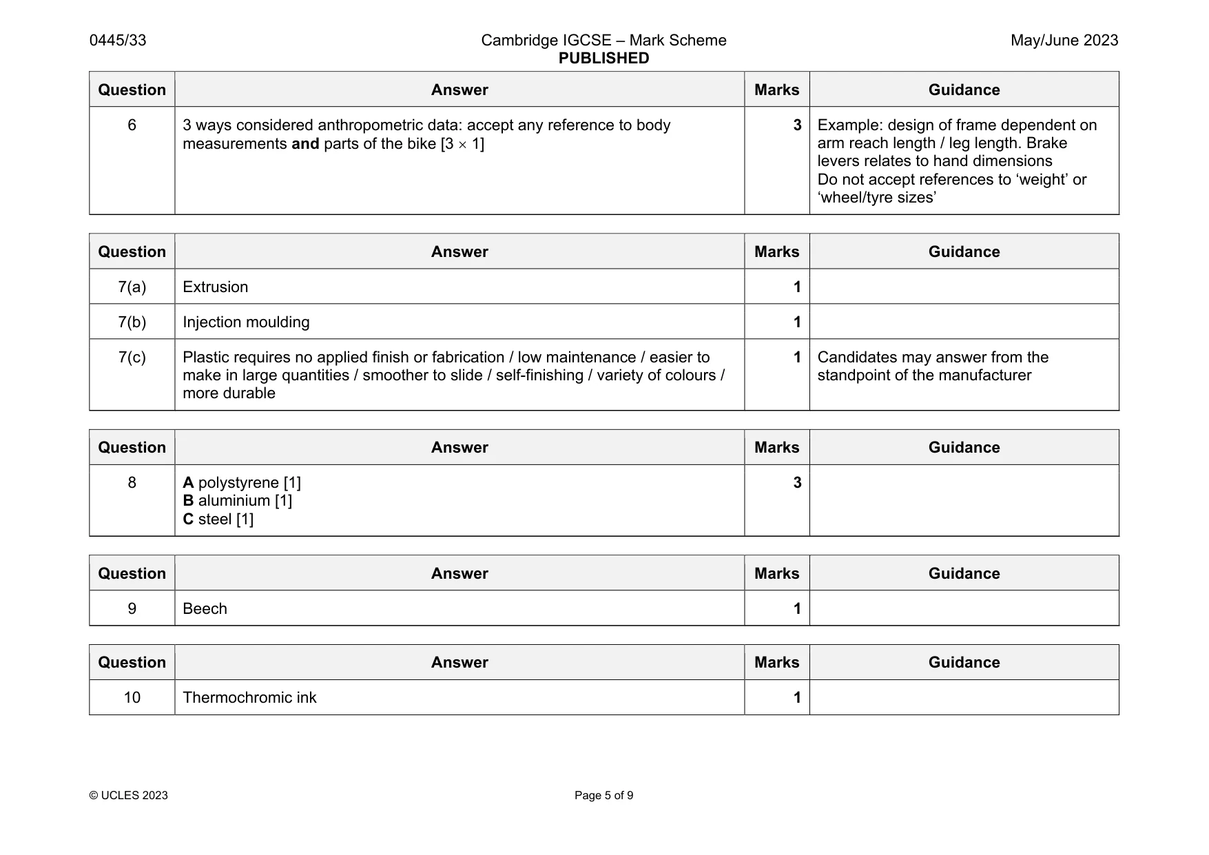
Answers below. Sit the paper first if you are practising.
Questions as text
Q1 · A chair that can be used when camping
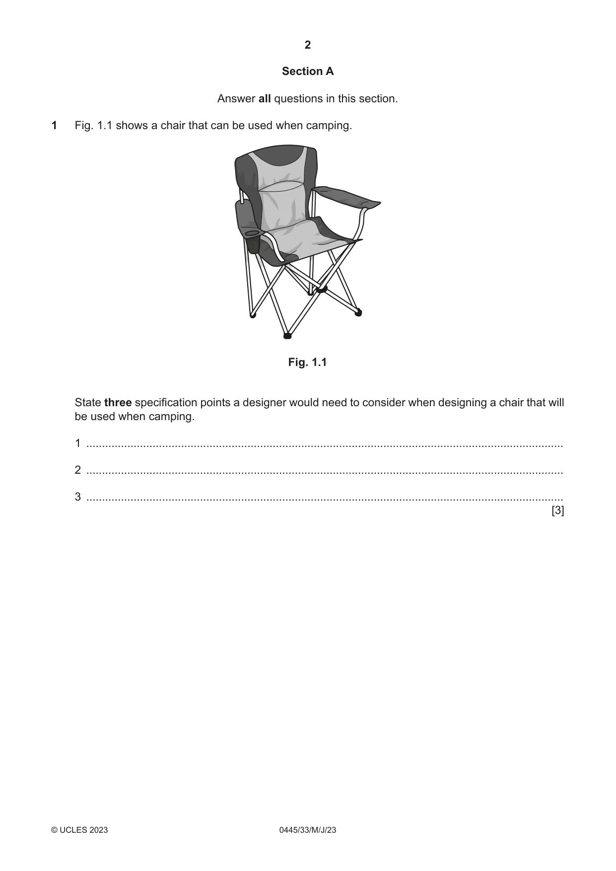
1 Fig. 1.1 shows a chair that can be used when camping. Fig. 1.1 State three specification points a designer would need to consider when designing a chair that will be used when camping. 1 ....................................................................................................................................................... 2 ....................................................................................................................................................... 3 ....................................................................................................................................................... [3]
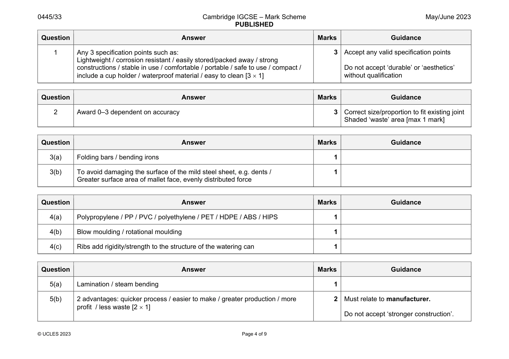
Mark scheme: 1 Any 3 specification points such as: Lightweight / corrosion resistant / easily stored/packed away / strong constructions / stable in use / comfortable / portable / safe to use / compact / include a cup holder / waterproof material / easy to clean [3 1] Do not accept ‘durable’ or ‘aesthetics’ without qualification
Q2 · Two parts, A and B, of an incomplete tee bridle joint
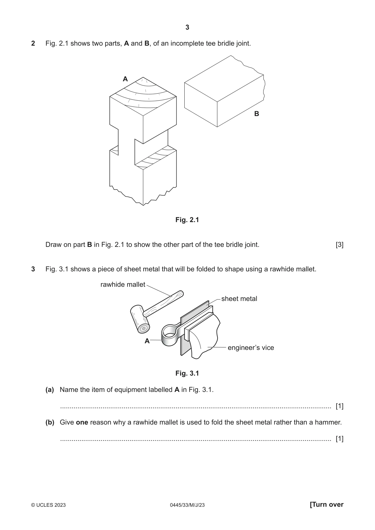
2 Fig. 2.1 shows two parts, A and B, of an incomplete tee bridle joint. A B Fig. 2.1 Draw on part B in Fig. 2.1 to show the other part of the tee bridle joint. [3]
Mark scheme: 2 Award 0–3 dependent on accuracy 3 Correct size/proportion to fit existing joint Shaded ‘waste’ area [max 1 mark]
Q3 · A piece of sheet metal that will be folded to shape using a rawhide mallet
3 Fig. 3.1 shows a piece of sheet metal that will be folded to shape using a rawhide mallet. rawhide mallet sheet metal A engineer’s vice Fig. 3.1 (a) Name the item of equipment labelled A in Fig. 3.1. ............................................................................................................................................. [1] (b) Give one reason why a rawhide mallet is used to fold the sheet metal rather than a hammer. ............................................................................................................................................. [1]
Mark scheme: 3(a) Folding bars / bending irons 1 3(b) To avoid damaging the surface of the mild steel sheet, e.g. dents / Greater surface area of mallet face, evenly distributed force 1
Q4 · A watering can made of plastic
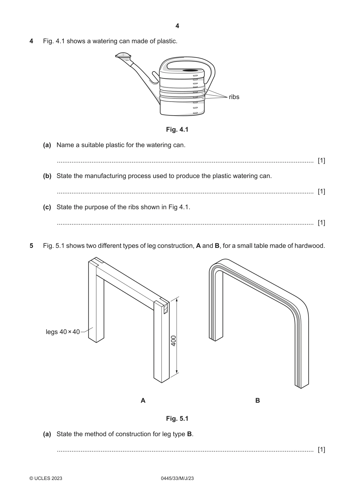
4 Fig. 4.1 shows a watering can made of plastic. ribs Fig. 4.1 (a) Name a suitable plastic for the watering can. ............................................................................................................................................. [1] (b) State the manufacturing process used to produce the plastic watering can. ............................................................................................................................................. [1] (c) State the purpose of the ribs shown in Fig 4.1. ............................................................................................................................................. [1]
Mark scheme: 4(a) Polypropylene / PP / PVC / polyethylene / PET / HDPE / ABS / HIPS 1 4(b) Blow moulding / rotational moulding 1 4(c) Ribs add rigidity/strength to the structure of the watering can 1
Q5 · Two different types of leg construction, A and B, for a small table made of hardwood
5 Fig. 5.1 shows two different types of leg construction, A and B, for a small table made of hardwood. legs 40 × 40 400 A B Fig. 5.1 (a) State the method of construction for leg type B. ............................................................................................................................................. [1] (b) Give two advantages to a manufacturer of producing leg type B rather than leg type A. 1 ................................................................................................................................................ 2 ................................................................................................................................................ [2]
Mark scheme: 5(a) Lamination / steam bending 1 5(b) 2 advantages: quicker process / easier to make / greater production / more profit / less waste [2 1] 2 Must relate to manufacturer. Do not accept ‘stronger construction’.
Question 6
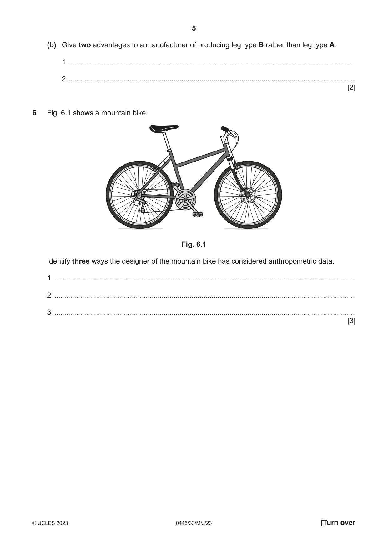
6 Fig. 6.1 shows a mountain bike. Fig. 6.1 Identify three ways the designer of the mountain bike has considered anthropometric data. 1 ....................................................................................................................................................... 2 ....................................................................................................................................................... 3 ....................................................................................................................................................... [3]
Mark scheme: 6 3 ways considered anthropometric data: accept any reference to body measurements and parts of the bike [3 1] 3 Example: design of frame dependent on arm reach length / leg length. Brake levers relates to hand dimensions Do not accept references to ‘weight’ or ‘wheel/tyre sizes’
Q7 · Views of a coat rack with adjustable sliders
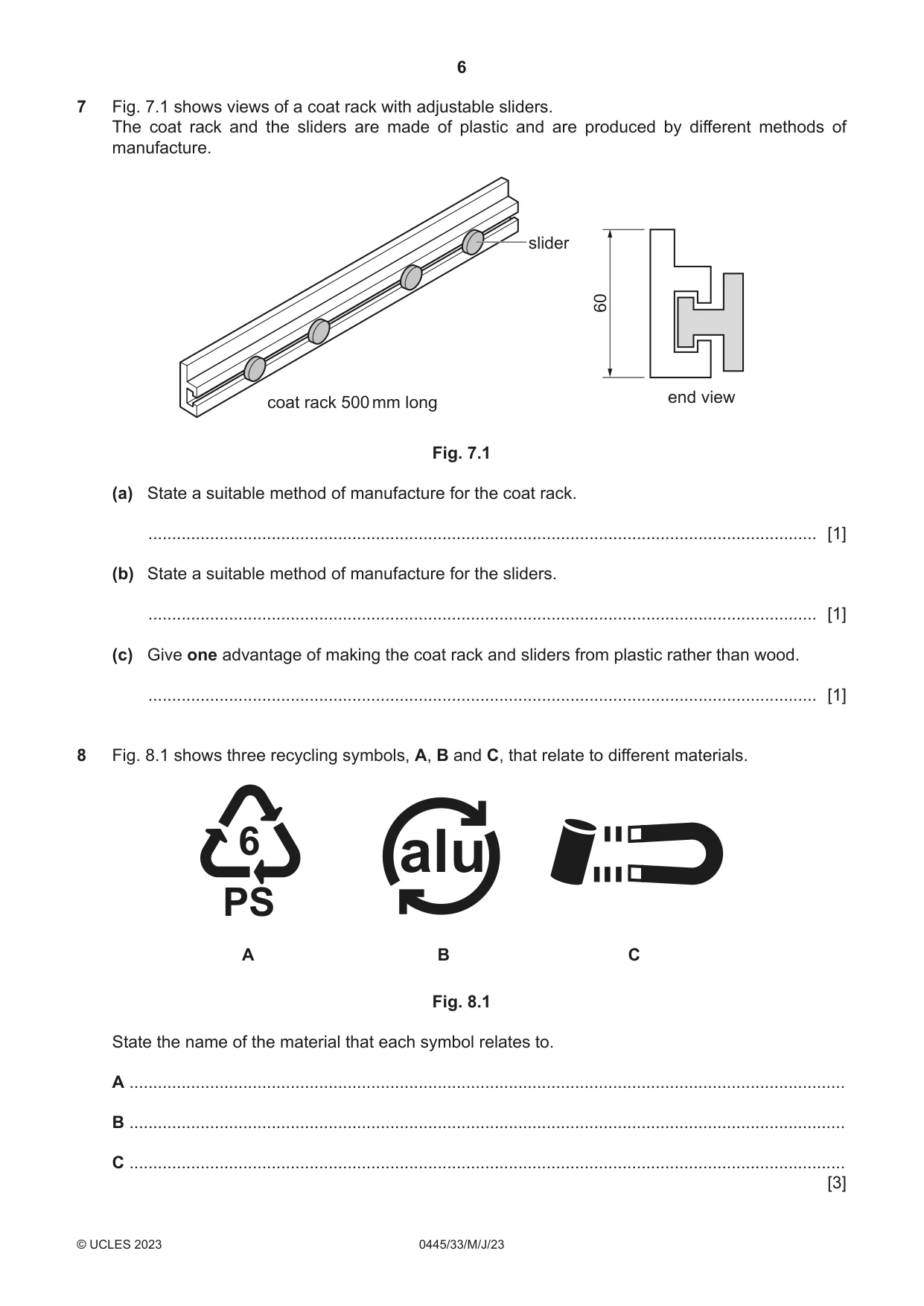
7 Fig. 7.1 shows views of a coat rack with adjustable sliders. The coat rack and the sliders are made of plastic and are produced by different methods of manufacture. slider 60 end view coat rack 500 mm long Fig. 7.1 (a) State a suitable method of manufacture for the coat rack. ............................................................................................................................................. [1] (b) State a suitable method of manufacture for the sliders. ............................................................................................................................................. [1] (c) Give one advantage of making the coat rack and sliders from plastic rather than wood. ............................................................................................................................................. [1]
Mark scheme: 7(a) Extrusion 1 7(b) Injection moulding 1 7(c) Plastic requires no applied finish or fabrication / low maintenance / easier to make in large quantities / smoother to slide / self-finishing / variety of colours / more durable 1 Candidates may answer from the standpoint of the manufacturer
Q8 · Three recycling symbols, A, B and C, that relate to different materials
8 Fig. 8.1 shows three recycling symbols, A, B and C, that relate to different materials. 6 alu PS A B C Fig. 8.1 State the name of the material that each symbol relates to. A ....................................................................................................................................................... B ....................................................................................................................................................... C ....................................................................................................................................................... [3]
Mark scheme: 8 A polystyrene [1] B aluminium [1] C steel [1] 3
Q9 · Select from the list below the material that corresponds to the description
9 Select from the list below the material that corresponds to the description. MDF parana pine beech blockboard ash Hardwood, close-grained, withstands wear and shocks, used to make toys and flooring. .................................................................................................................................................... [1]
Mark scheme: 9 Beech 1
Q10 · A battery with a test strip that allows the user to check the condition of the battery
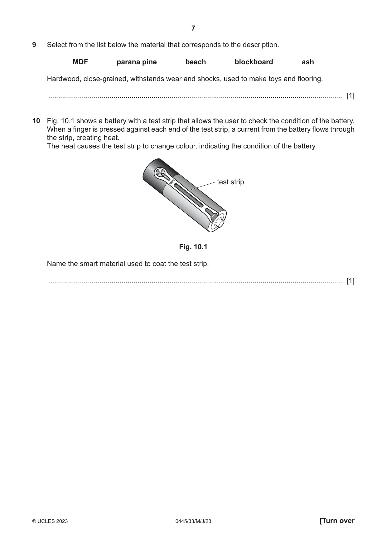
10 Fig. 10.1 shows a battery with a test strip that allows the user to check the condition of the battery. When a finger is pressed against each end of the test strip, a current from the battery flows through the strip, creating heat. The heat causes the test strip to change colour, indicating the condition of the battery. test strip Fig. 10.1 Name the smart material used to coat the test strip. .................................................................................................................................................... [1]
Mark scheme: 10 Thermochromic ink 1
Q11 · Views of a photograph frame held in a stand
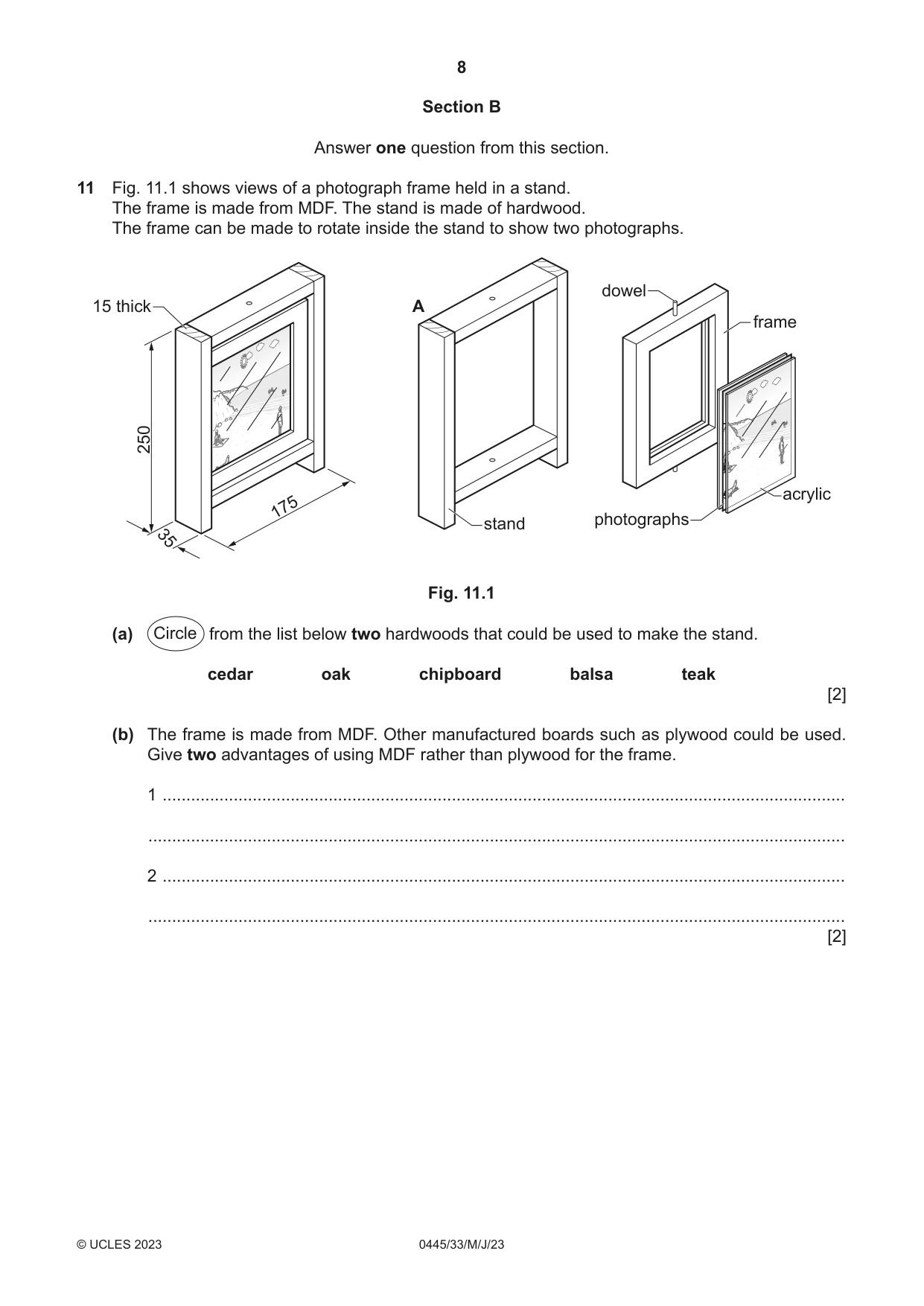
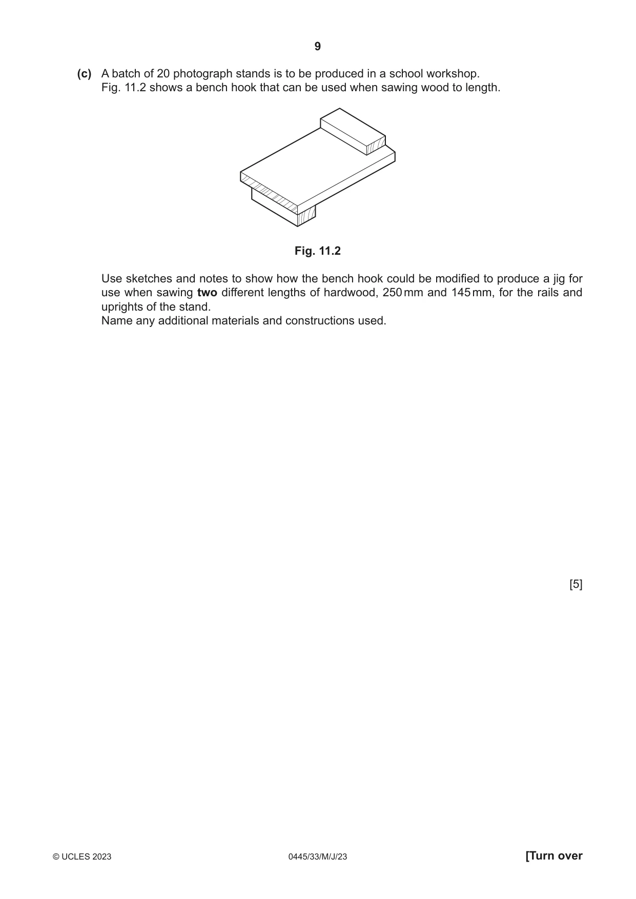
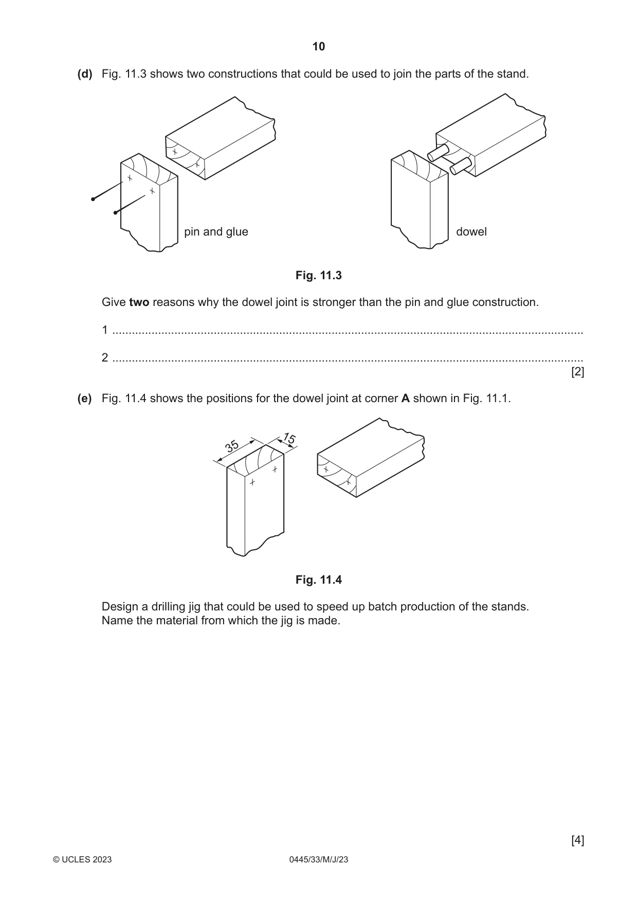
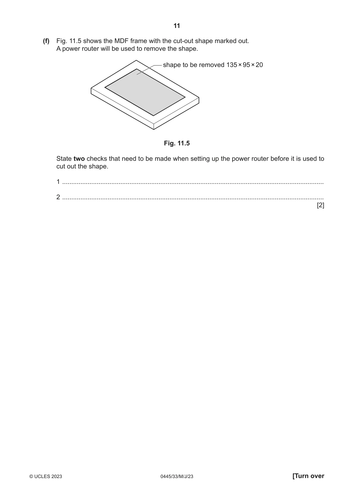
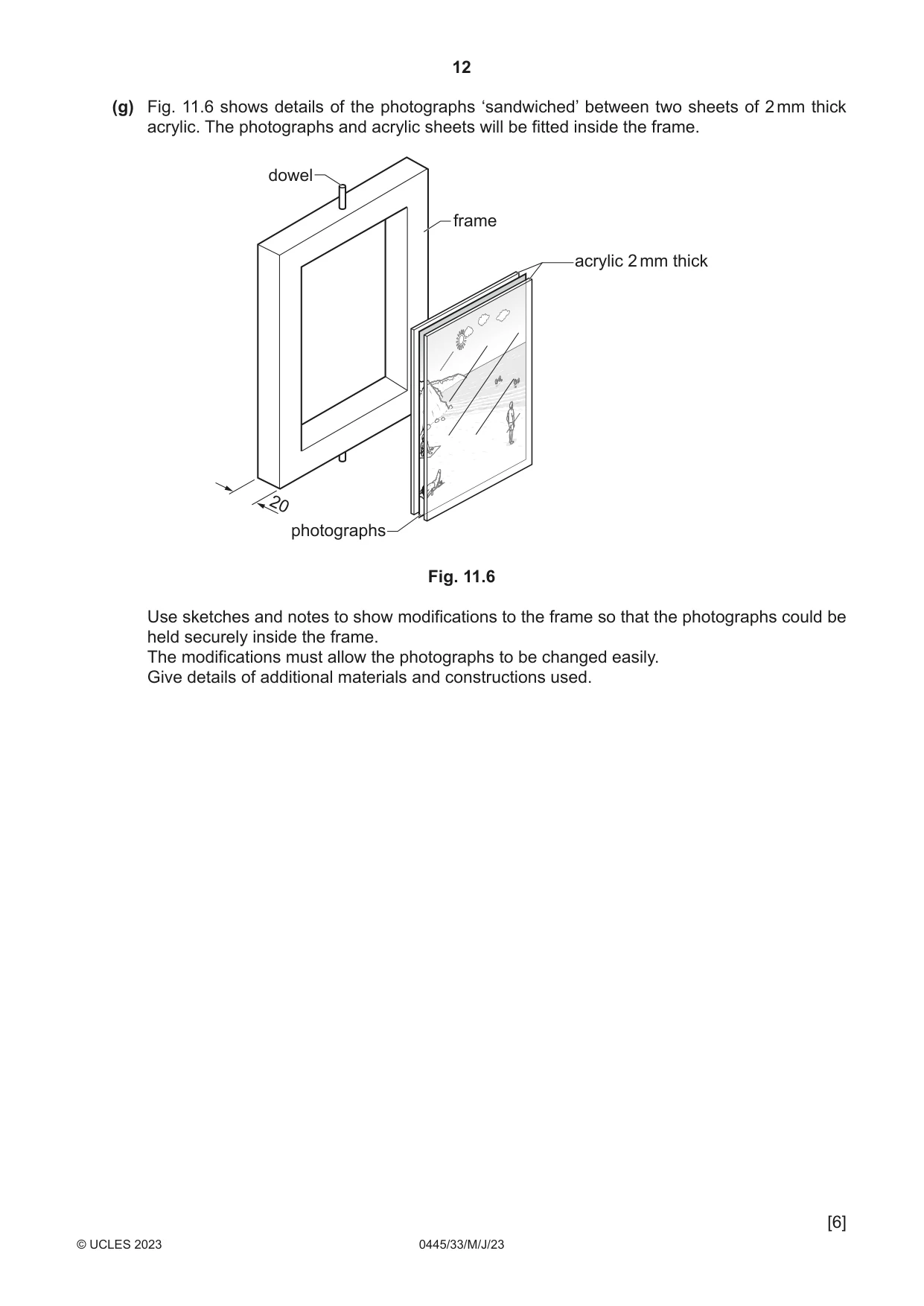
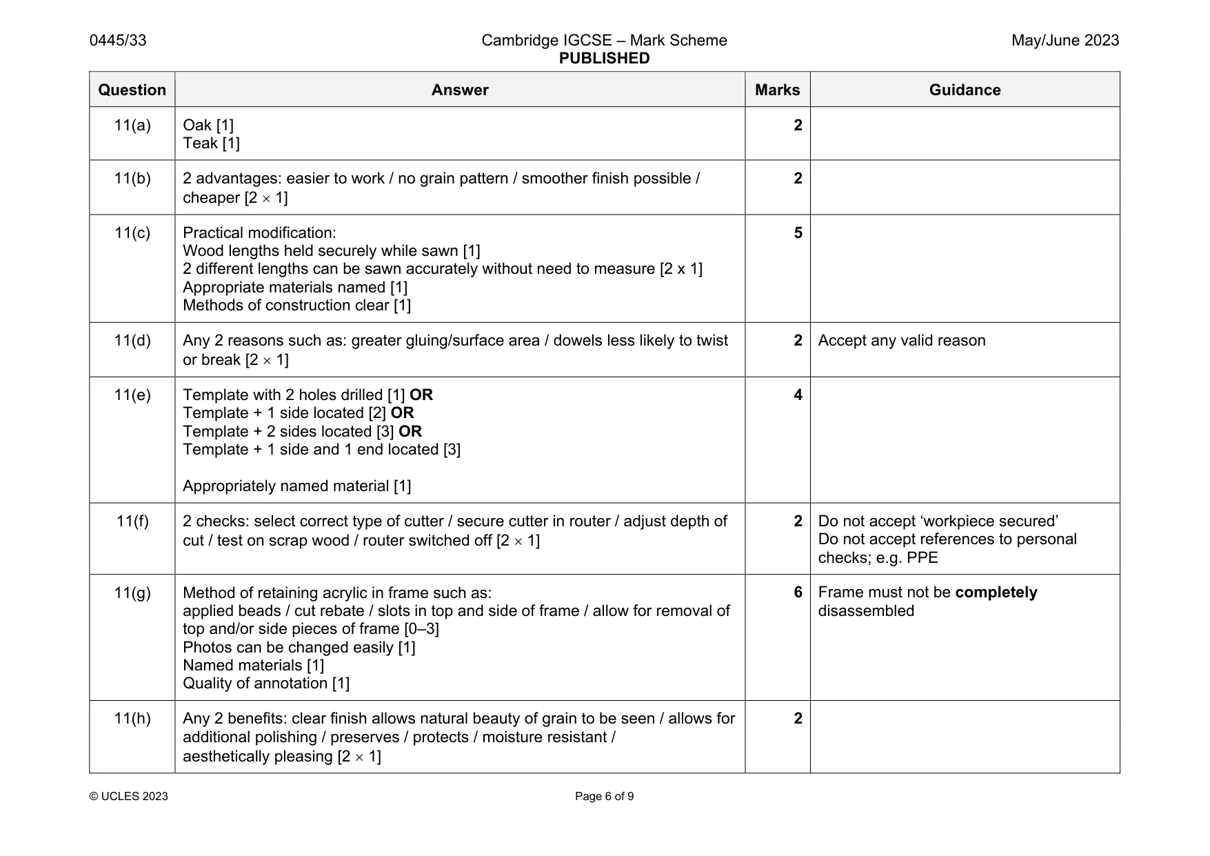
11 Fig. 11.1 shows views of a photograph frame held in a stand. The frame is made from MDF. The stand is made of hardwood. The frame can be made to rotate inside the stand to show two photographs. dowel 15 thick A frame 250 acrylic 175 stand photographs 35 Fig. 11.1 (a) Circle from the list below two hardwoods that could be used to make the stand. cedar oak chipboard balsa teak [2] (b) The frame is made from MDF. Other manufactured boards such as plywood could be used. Give two advantages of using MDF rather than plywood for the frame. 1 ................................................................................................................................................ ................................................................................................................................................... 2 ................................................................................................................................................ ................................................................................................................................................... [2] (c) A batch of 20 photograph stands is to be produced in a school workshop. Fig. 11.2 shows a bench hook that can be used when sawing wood to length. Fig. 11.2 Use sketches and notes to show how the bench hook could be modified to produce a jig for use when sawing two different lengths of hardwood, 250 mm and 145 mm, for the rails and uprights of the stand. Name any additional materials and constructions used. [5] (d) Fig. 11.3 shows two constructions that could be used to join the parts of the stand. pin and glue dowel Fig. 11.3 Give two reasons why the dowel joint is stronger than the pin and glue construction. 1 ................................................................................................................................................ 2 ................................................................................................................................................ [2] (e) Fig. 11.4 shows the positions for the dowel joint at corner A shown in Fig. 11.1. 15 35 Fig. 11.4 Design a drilling jig that could be used to speed up batch production of the stands. Name the material from which the jig is made. [4] (f) Fig. 11.5 shows the MDF frame with the cut-out shape marked out. A power router will be used to remove the shape. shape to be removed 135 × 95 × 20 Fig. 11.5 State two checks that need to be made when setting up the power router before it is used to cut out the shape. 1 ................................................................................................................................................ 2 ................................................................................................................................................ [2] (g) Fig. 11.6 shows details of the photographs ‘sandwiched’ between two sheets of 2 mm thick acrylic. The photographs and acrylic sheets will be fitted inside the frame. dowel frame acrylic 2 mm thick 20 photographs Fig. 11.6 Use sketches and notes to show modifications to the frame so that the photographs could be held securely inside the frame. The modifications must allow the photographs to be changed easily. Give details of additional materials and constructions used. [6] (h) The hardwood stand will have a clear polished finish. Give two benefits of applying a clear polished finish to the hardwood stand. 1 ................................................................................................................................................ 2 ................................................................................................................................................ [2]
Mark scheme: 11(a) Oak [1] Teak [1] 2 11(b) 2 advantages: easier to work / no grain pattern / smoother finish possible / cheaper [2 1] 2 11(c) Practical modification: Wood lengths held securely while sawn [1] 2 different lengths can be sawn accurately without need to measure [2 x 1] Appropriate materials named [1] Methods of construction clear [1] 5 11(d) Any 2 reasons such as: greater gluing/surface area / dowels less likely to twist or break [2 1] 2 Accept any valid reason 11(e) Template with 2 holes drilled [1] OR Template + 1 side located [2] OR Template + 2 sides located [3] OR Template + 1 side and 1 end located [3] Appropriately named material [1] 4 11(f) 2 checks: select correct type of cutter / secure cutter in router / adjust depth of cut / test on scrap wood / router switched off [2 1] 2 Do not accept ‘workpiece secured’ Do not accept references to personal checks; e.g. PPE 11(g) Method of retaining acrylic in frame such as: applied beads / cut rebate / slots in top and side of frame / allow for removal of top and/or side pieces of frame [0–3] Photos can be changed easily [1] Named materials [1] Quality of annotation [1] 6 Frame must not be completely disassembled 11(h) Any 2 benefits: clear finish allows natural beauty of grain to be seen / allows for additional polishing / preserves / protects / moisture resistant / aesthetically pleasing [2 1] 2
Q12 · An incomplete design for a small table
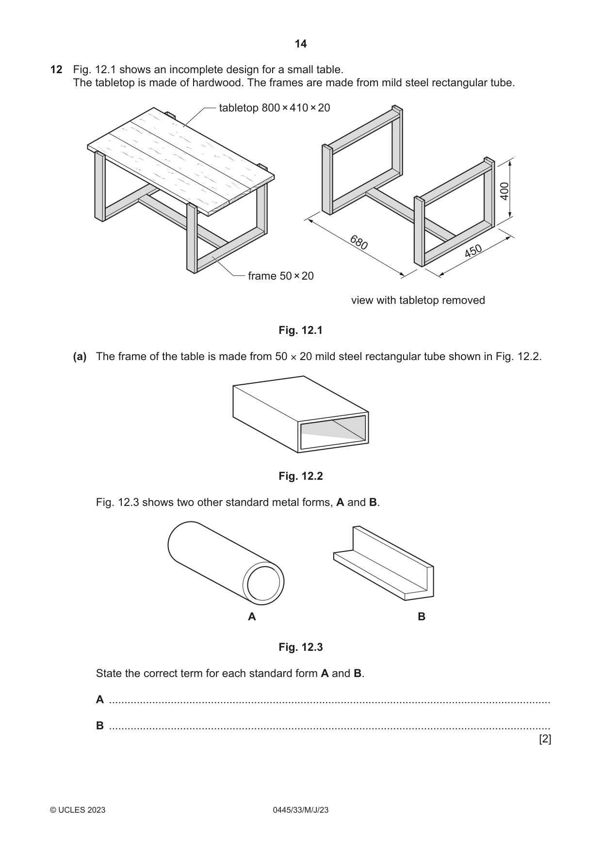
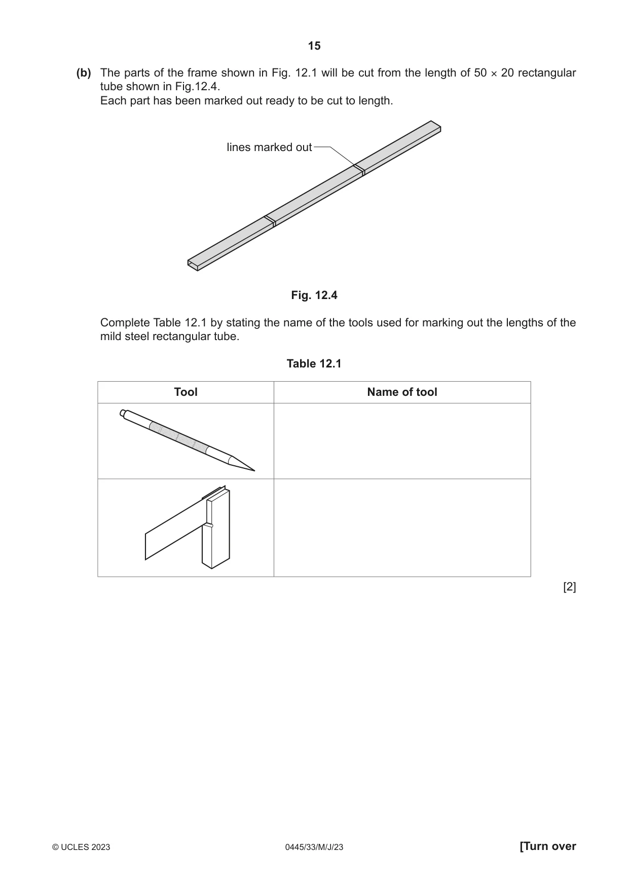
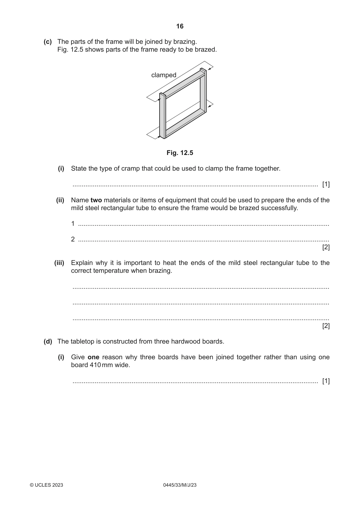
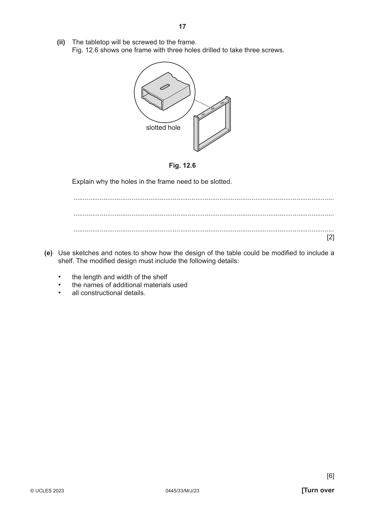
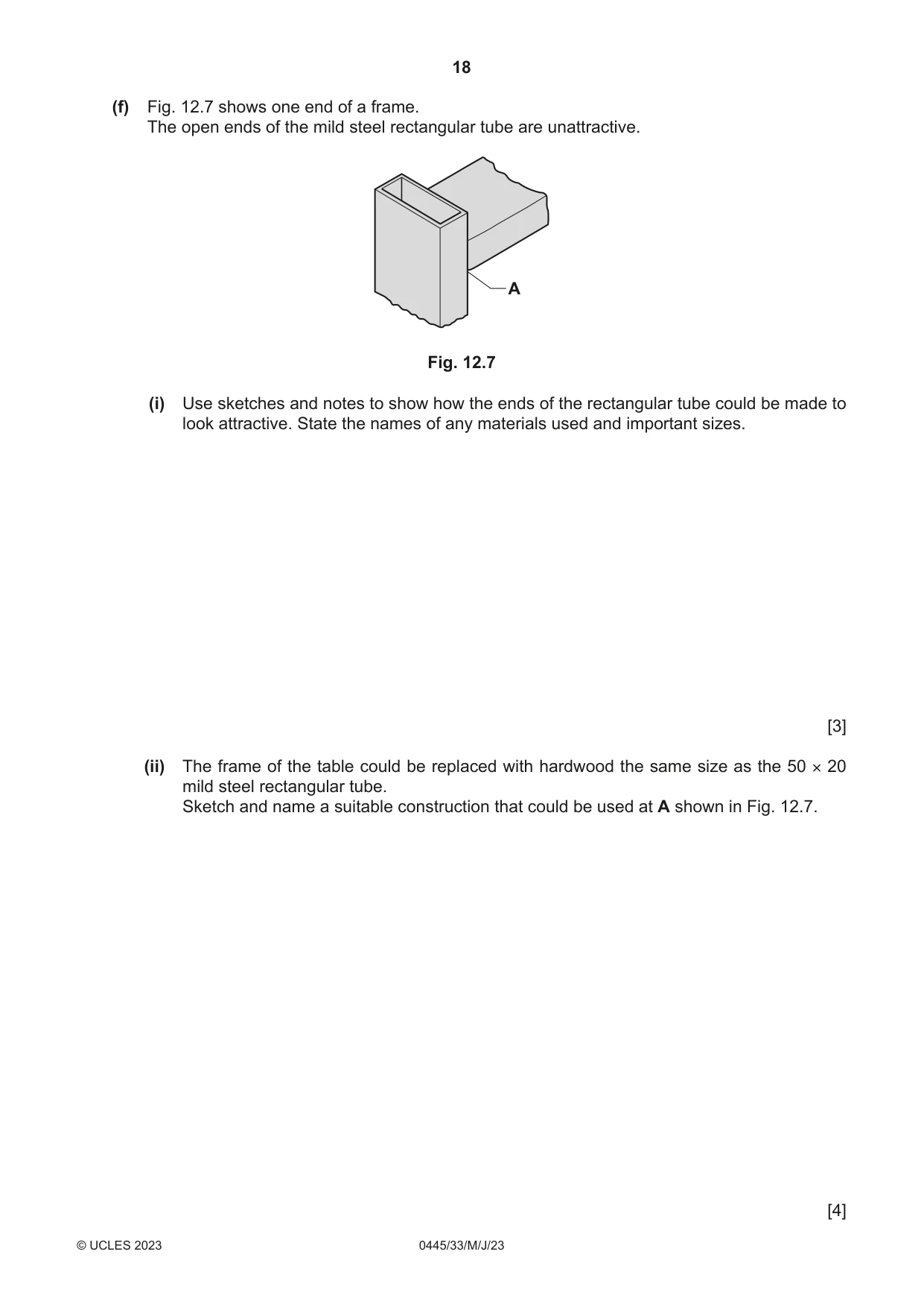
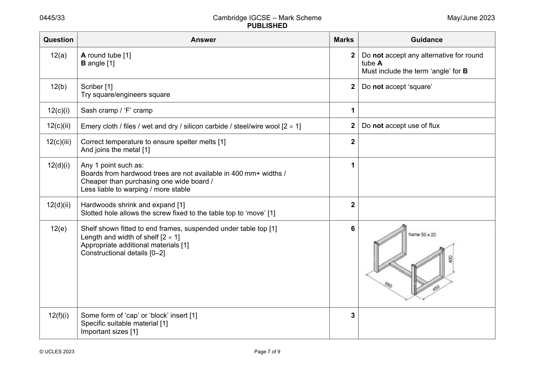
12 Fig. 12.1 shows an incomplete design for a small table. The tabletop is made of hardwood. The frames are made from mild steel rectangular tube. tabletop 800 × 410 × 20 400 680 450 frame 50 × 20 view with tabletop removed Fig. 12.1 (a) The frame of the table is made from 50 × 20 mild steel rectangular tube shown in Fig. 12.2. Fig. 12.2 Fig. 12.3 shows two other standard metal forms, A and B. A B Fig. 12.3 State the correct term for each standard form A and B. A ............................................................................................................................................... B ............................................................................................................................................... [2] (b) The parts of the frame shown in Fig. 12.1 will be cut from the length of 50 × 20 rectangular tube shown in Fig.12.4. Each part has been marked out ready to be cut to length. lines marked out Fig. 12.4 Complete Table 12.1 by stating the name of the tools used for marking out the lengths of the mild steel rectangular tube. Table 12.1 Tool Name of tool [2] (c) The parts of the frame will be joined by brazing. Fig. 12.5 shows parts of the frame ready to be brazed. clamped Fig. 12.5 (i) State the type of cramp that could be used to clamp the frame together. ..................................................................................................................................... [1] (ii) Name two materials or items of equipment that could be used to prepare the ends of the mild steel rectangular tube to ensure the frame would be brazed successfully. 1 ........................................................................................................................................ 2 ........................................................................................................................................ [2] (iii) Explain why it is important to heat the ends of the mild steel rectangular tube to the correct temperature when brazing. ........................................................................................................................................... ........................................................................................................................................... ........................................................................................................................................... [2] (d) The tabletop is constructed from three hardwood boards. (i) Give one reason why three boards have been joined together rather than using one board 410 mm wide. ..................................................................................................................................... [1] (ii) The tabletop will be screwed to the frame. Fig. 12.6 shows one frame with three holes drilled to take three screws. slotted hole Fig. 12.6 Explain why the holes in the frame need to be slotted. ........................................................................................................................................... ........................................................................................................................................... ........................................................................................................................................... [2] (e) Use sketches and notes to show how the design of the table could be modified to include a shelf. The modified design must include the following details: • the length and width of the shelf • the names of additional materials used • all constructional details. [6] (f) Fig. 12.7 shows one end of a frame. The open ends of the mild steel rectangular tube are unattractive. A Fig. 12.7 (i) Use sketches and notes to show how the ends of the rectangular tube could be made to look attractive. State the names of any materials used and important sizes. [3] (ii) The frame of the table could be replaced with hardwood the same size as the 50 × 20 mild steel rectangular tube. Sketch and name a suitable construction that could be used at A shown in Fig. 12.7. [4]
Mark scheme: 12(a) A round tube [1] B angle [1] 2 Do not accept any alternative for round tube A Must include the term ‘angle’ for B 12(b) Scriber [1] Try square/engineers square 2 Do not accept ‘square’ 12(c)(i) Sash cramp / ‘F’ cramp 1 12(c)(ii) Emery cloth / files / wet and dry / silicon carbide / steel/wire wool [2 1] 2 Do not accept use of flux 12(c)(iii) Correct temperature to ensure spelter melts [1] And joins the metal [1] 2 12(d)(i) Any 1 point such as: Boards from hardwood trees are not available in 400 mm+ widths / Cheaper than purchasing one wide board / Less liable to warping / more stable 1 12(d)(ii) Hardwoods shrink and expand [1] Slotted hole allows the screw fixed to the table top to ‘move’ [1] 2 12(e) Shelf shown fitted to end frames, suspended under table top [1] Length and width of shelf [2 1] Appropriate additional materials [1] Constructional details [0–2] 6 12(f)(i) Some form of ‘cap’ or ‘block’ insert [1] Specific suitable material [1] Important sizes [1] 3 Question Answer Marks Guidance 12(f)(ii) Suitable construction using 50 20 section hardwood: dowel / mortise and tenon / housing / biscuit named [1] Technical accuracy: correct size/proportion/orientation [0–3] 4 Accept K-D fittings: e.g. bloc fitting, cam lock
Q13 · A paint palette made of 3 mm thick acrylic
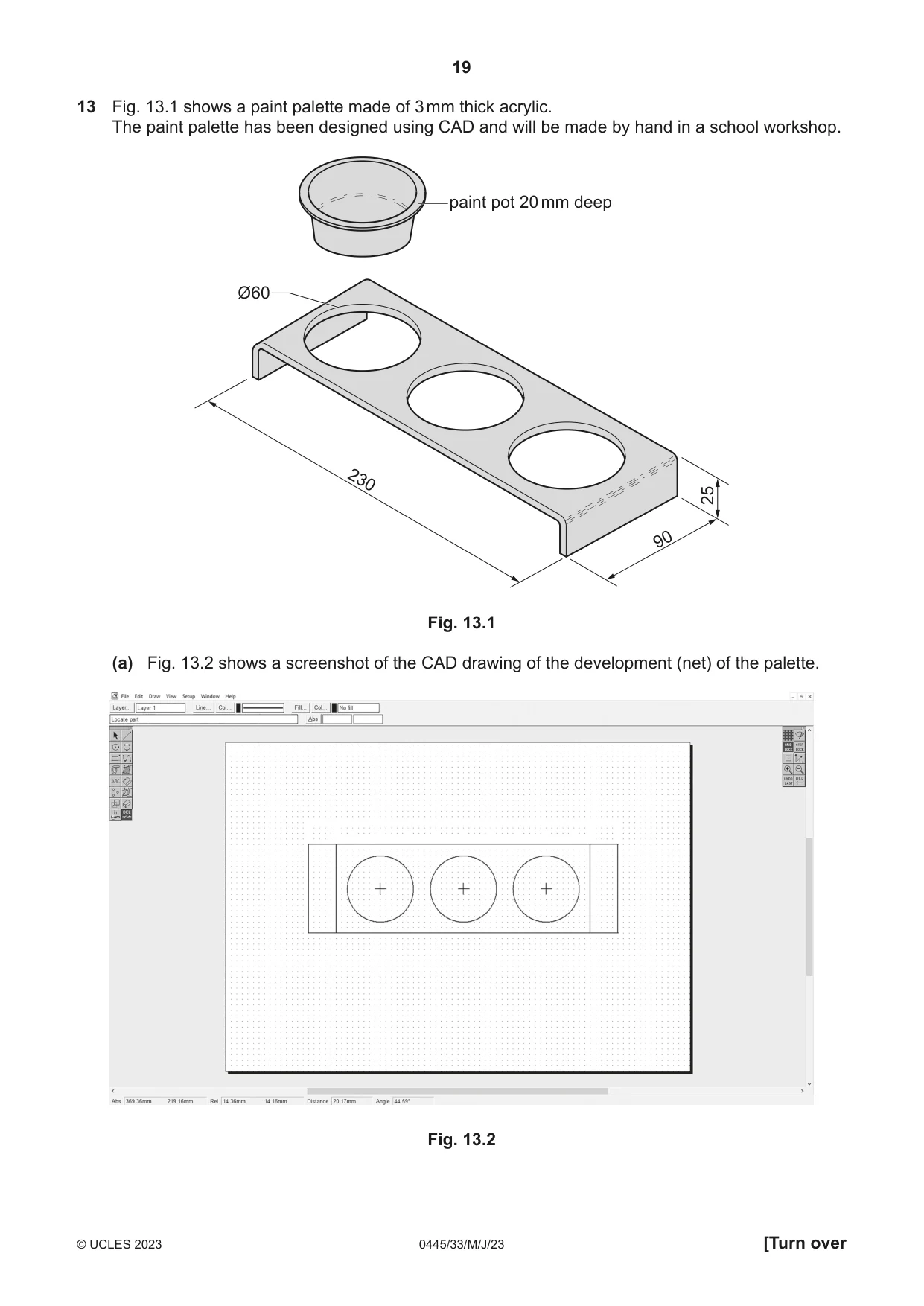
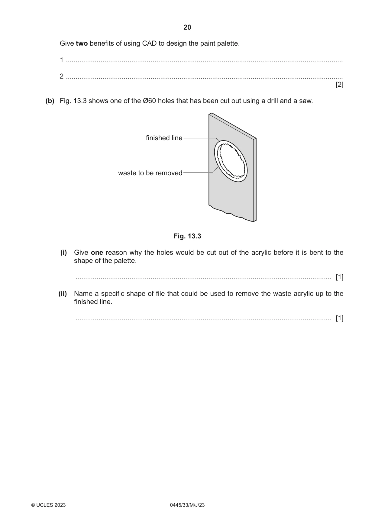
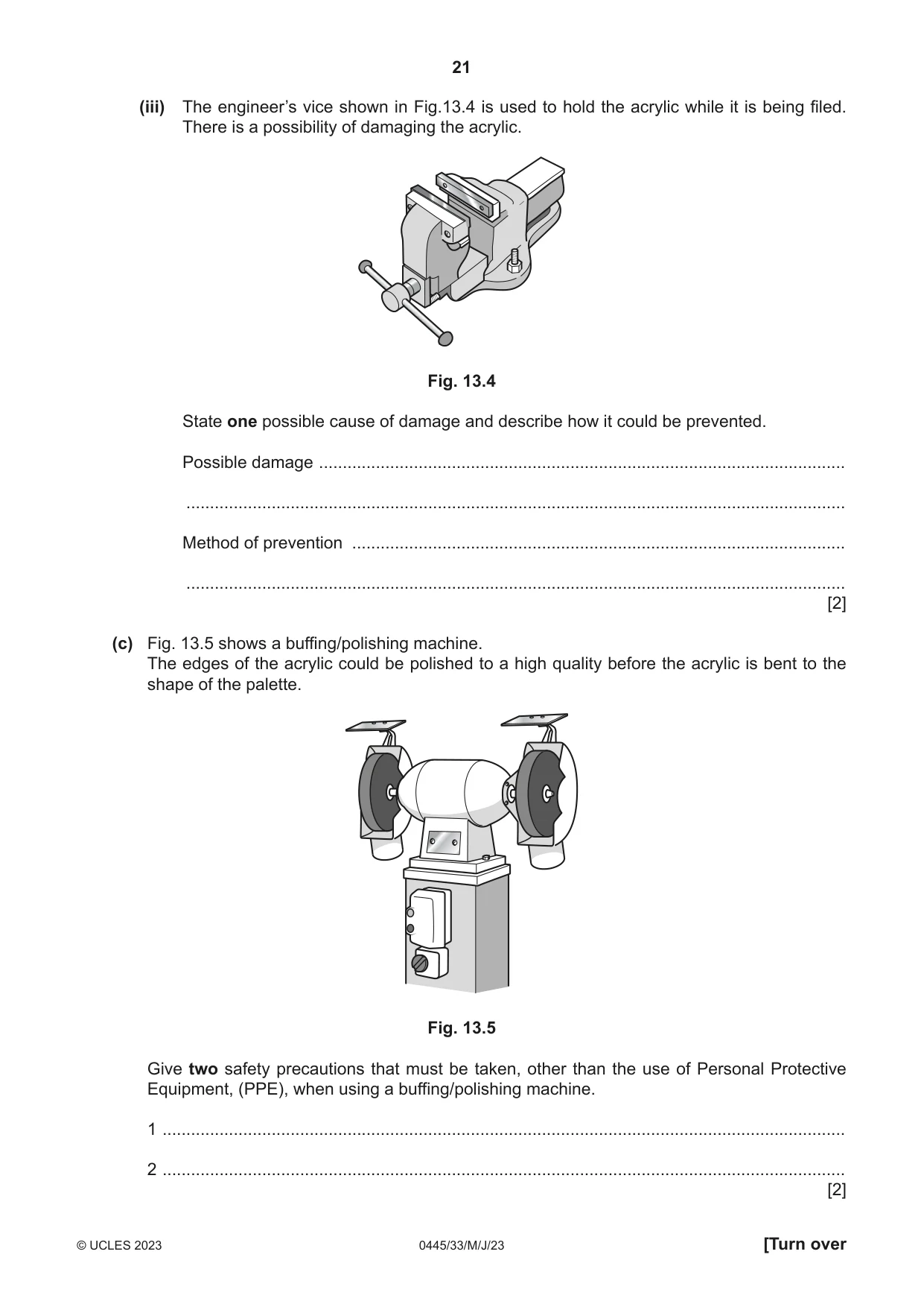
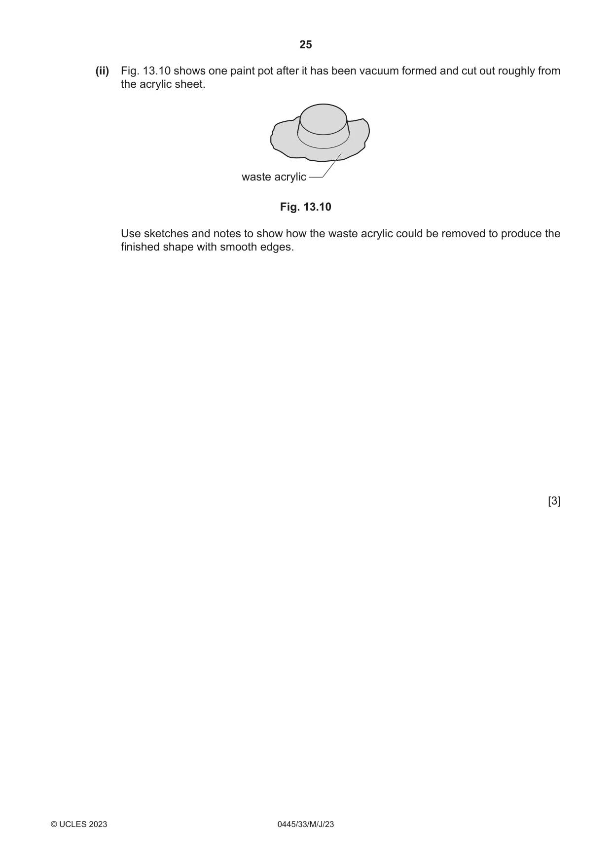
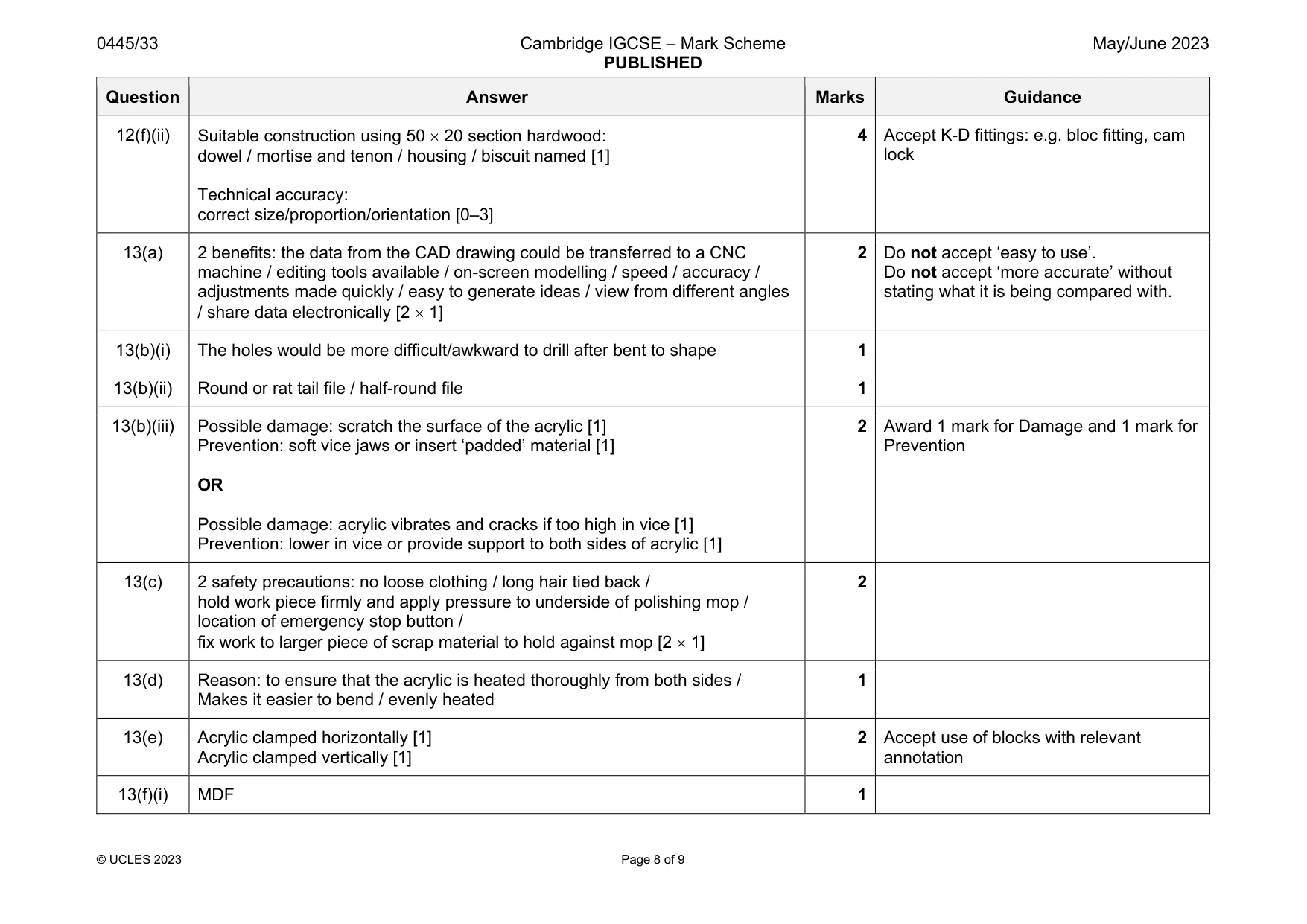
13 Fig. 13.1 shows a paint palette made of 3 mm thick acrylic. The paint palette has been designed using CAD and will be made by hand in a school workshop. paint pot 20 mm deep Ø60 230 25 90 Fig. 13.1 (a) Fig. 13.2 shows a screenshot of the CAD drawing of the development (net) of the palette. Fig. 13.2 Give two benefits of using CAD to design the paint palette. 1 ................................................................................................................................................ 2 ................................................................................................................................................ [2] (b) Fig. 13.3 shows one of the Ø60 holes that has been cut out using a drill and a saw. finished line waste to be removed Fig. 13.3 (i) Give one reason why the holes would be cut out of the acrylic before it is bent to the shape of the palette. ..................................................................................................................................... [1] (ii) Name a specific shape of file that could be used to remove the waste acrylic up to the finished line. ..................................................................................................................................... [1] (iii) The engineer’s vice shown in Fig.13.4 is used to hold the acrylic while it is being filed. There is a possibility of damaging the acrylic. Fig. 13.4 State one possible cause of damage and describe how it could be prevented. Possible damage ............................................................................................................... ........................................................................................................................................... Method of prevention ........................................................................................................ ........................................................................................................................................... [2] (c) Fig. 13.5 shows a buffing/polishing machine. The edges of the acrylic could be polished to a high quality before the acrylic is bent to the shape of the palette. Fig. 13.5 Give two safety precautions that must be taken, other than the use of Personal Protective Equipment, (PPE), when using a buffing/polishing machine. 1 ................................................................................................................................................ 2 ................................................................................................................................................ [2]
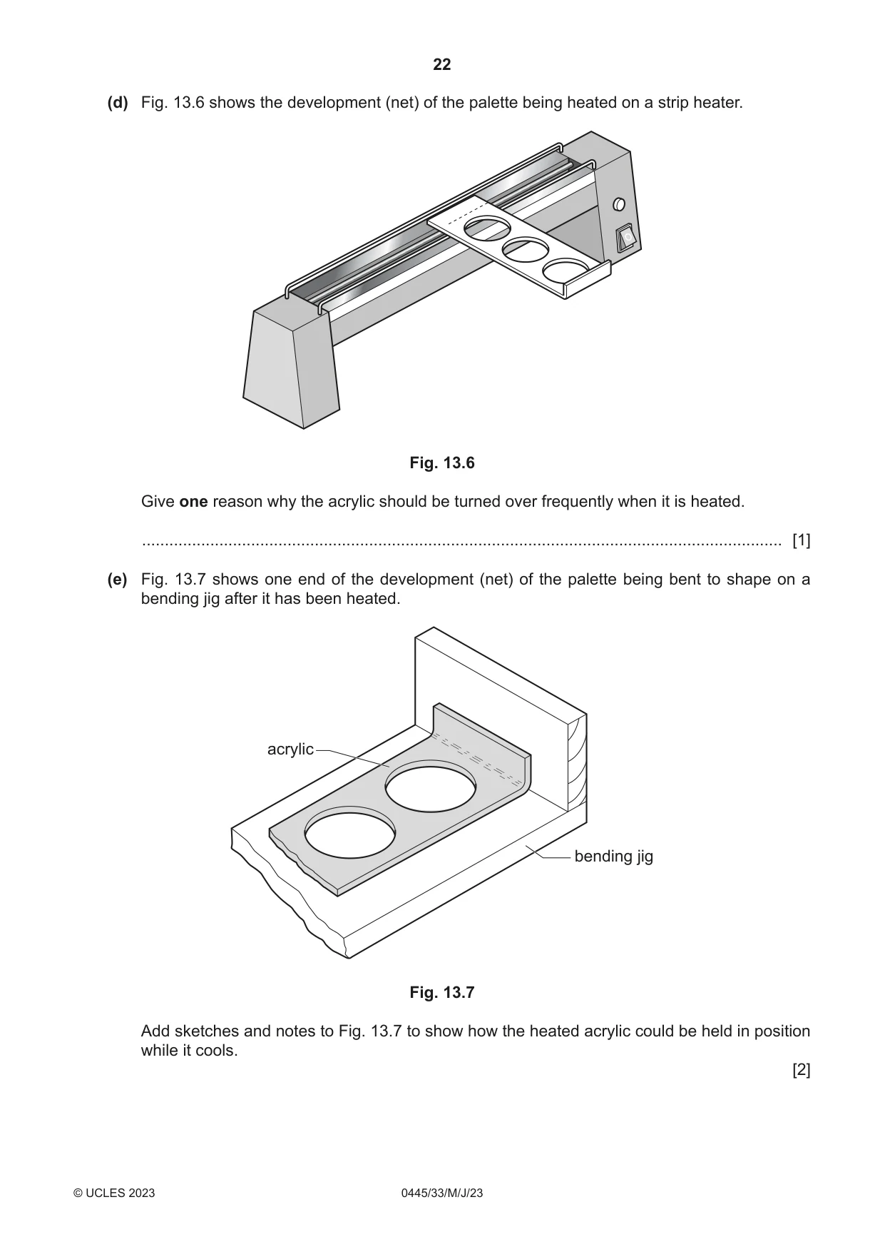
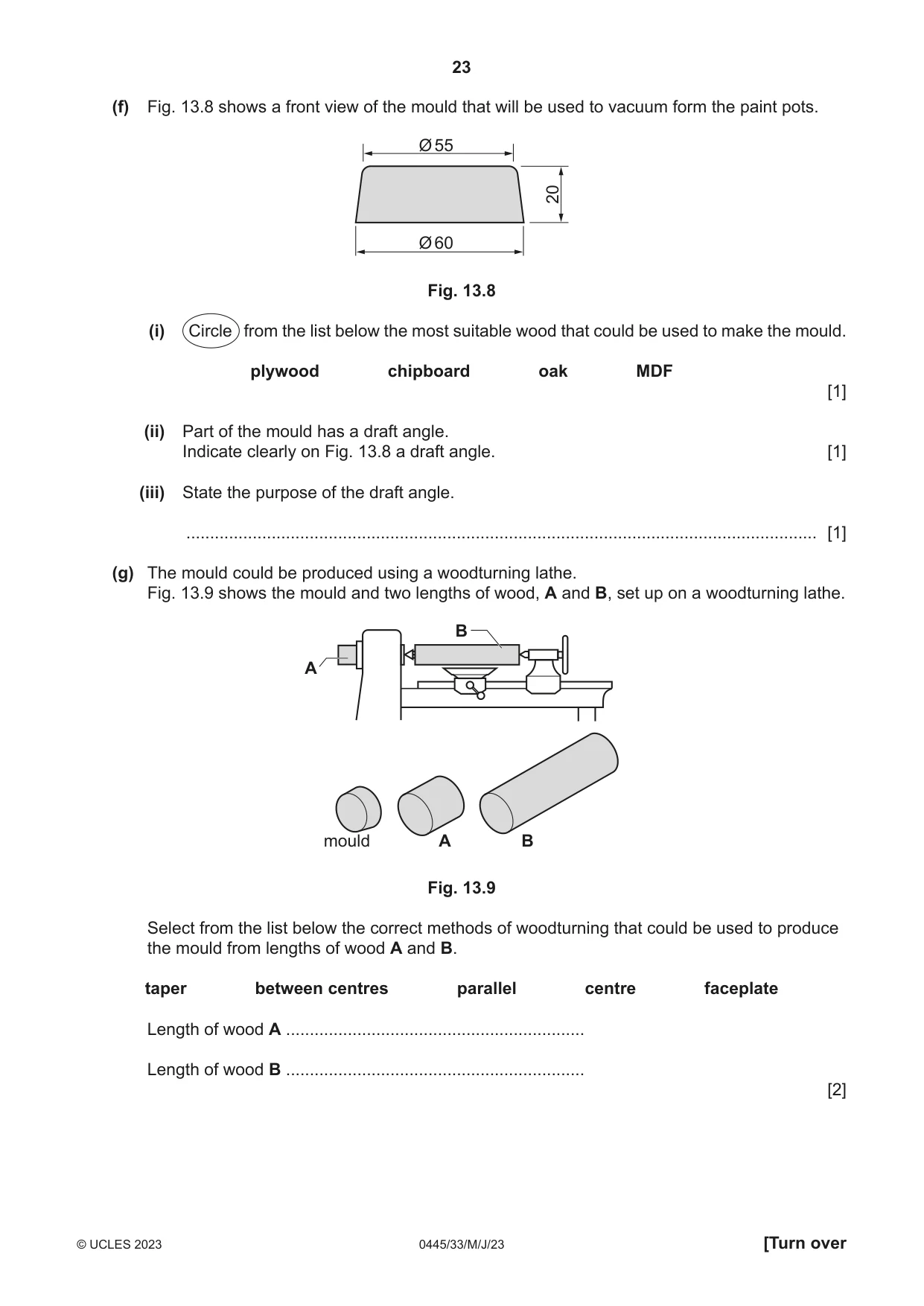
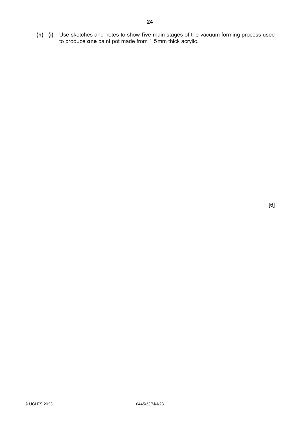
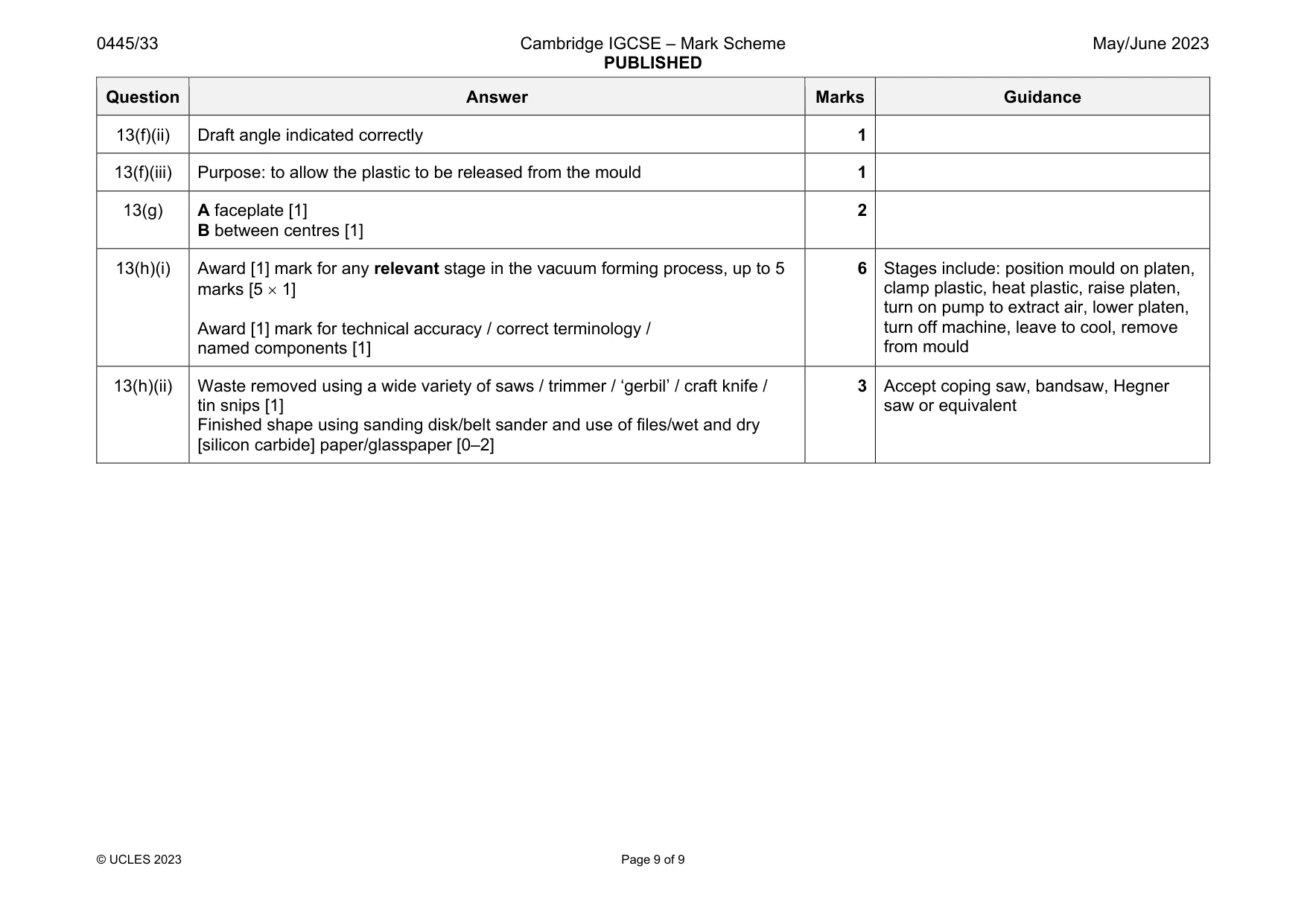
Mark scheme: 13(a) 2 benefits: the data from the CAD drawing could be transferred to a CNC machine / editing tools available / on-screen modelling / speed / accuracy / adjustments made quickly / easy to generate ideas / view from different angles / share data electronically [2 1] 2 Do not accept ‘easy to use’. Do not accept ‘more accurate’ without stating what it is being compared with. 13(b)(i) The holes would be more difficult/awkward to drill after bent to shape 1 13(b)(ii) Round or rat tail file / half-round file 1 13(b)(iii) Possible damage: scratch the surface of the acrylic [1] Prevention: soft vice jaws or insert ‘padded’ material [1] OR Possible damage: acrylic vibrates and cracks if too high in vice [1] Prevention: lower in vice or provide support to both sides of acrylic [1] 2 Award 1 mark for Damage and 1 mark for Prevention 13(c) 2 safety precautions: no loose clothing / long hair tied back / hold work piece firmly and apply pressure to underside of polishing mop / location of emergency stop button / fix work to larger piece of scrap material to hold against mop [2 1] 2 13(d) Reason: to ensure that the acrylic is heated thoroughly from both sides / Makes it easier to bend / evenly heated 1 13(e) Acrylic clamped horizontally [1] Acrylic clamped vertically [1] 2 Accept use of blocks with relevant annotation 13(f)(i) MDF 1 Question Answer Marks Guidance 13(f)(ii) Draft angle indicated correctly 1 13(f)(iii) Purpose: to allow the plastic to be released from the mould 1 13(g) A faceplate [1] B between centres [1] 2 13(h)(i) Award [1] mark for any relevant stage in the vacuum forming process, up to 5 marks [5 1] Award [1] mark for technical accuracy / correct terminology / named components [1] 6 Stages include: position mould on platen, clamp plastic, heat plastic, raise platen, turn on pump to extract air, lower platen, turn off machine, leave to cool, remove from mould 13(h)(ii) Waste removed using a wide variety of saws / trimmer / ‘gerbil’ / craft knife / tin snips [1] Finished shape using sanding disk/belt sander and use of files/wet and dry [silicon carbide] paper/glasspaper [0–2] 3 Accept coping saw, bandsaw, Hegner saw or equivalent
What was in this paper
The subtopics covered by these 13 questions, and how many questions each got. Open one in a new tab to see every Cambridge question on it.
What you needed in this session
Cambridge’s own grade thresholds for 2023 May/June, Paper 3 · Variant 3. A higher threshold means an easier paper — the bar moves with how the cohort did.