Cambridge IGCSE Design and Technology 0445 — 2022 May/June Paper 3 · Variant 1
0445/31/M/J/22 · 13 questions · 50 marks · ≈56 min
The question paper and its mark scheme, free to read here and free to download. This is Cambridge’s own paper, exactly as it was sat.
Question paper20 pages
Mark scheme8 pages
Answers below. Sit the paper first if you are practising.
Questions as text
Question 1
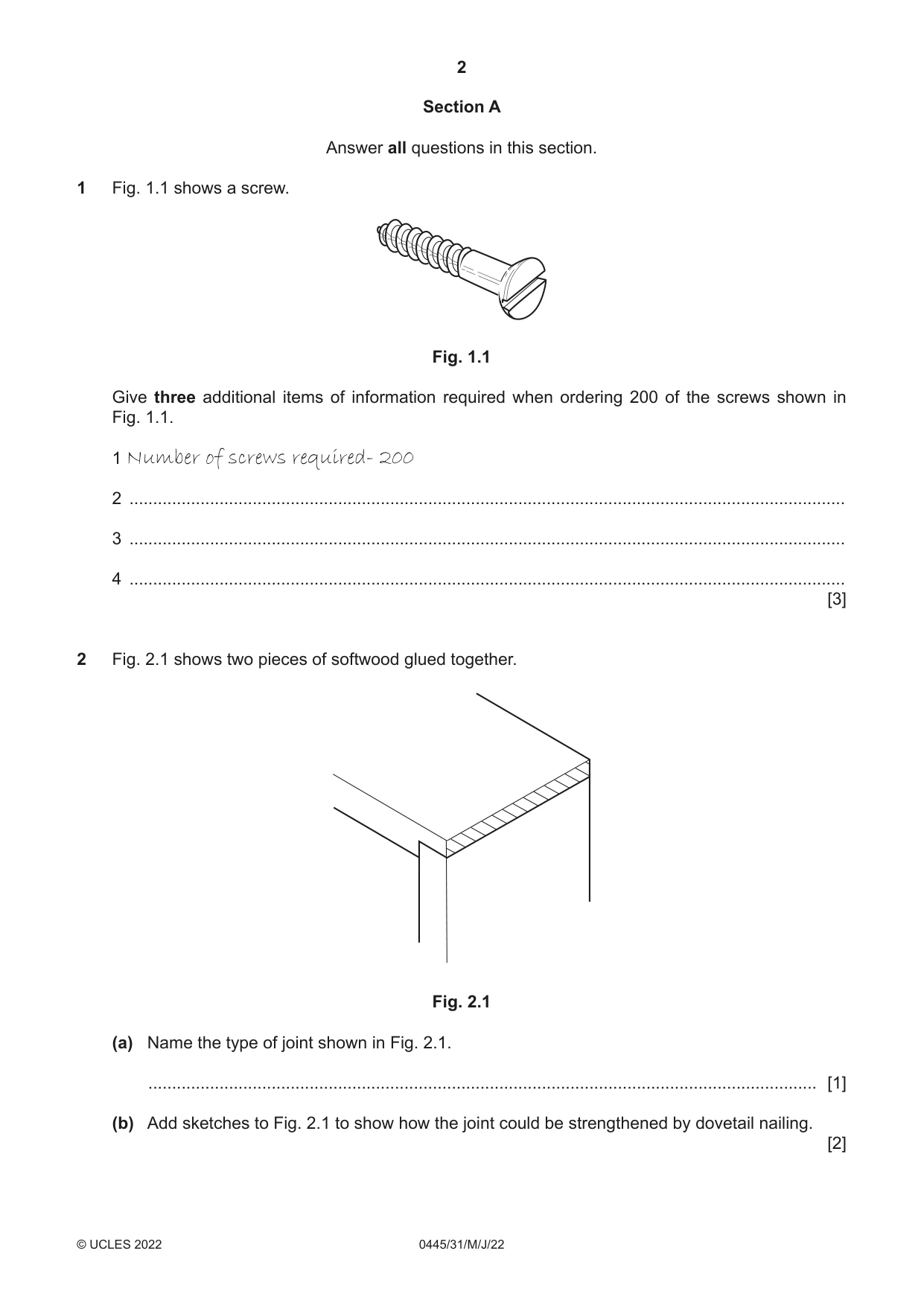
1 Fig. 1.1 shows a screw. Fig. 1.1 Give three additional items of information required when ordering 200 of the screws shown in Fig. 1.1. 1 Number of screws required- 200 2 ....................................................................................................................................................... 3 ....................................................................................................................................................... 4 ....................................................................................................................................................... [3]
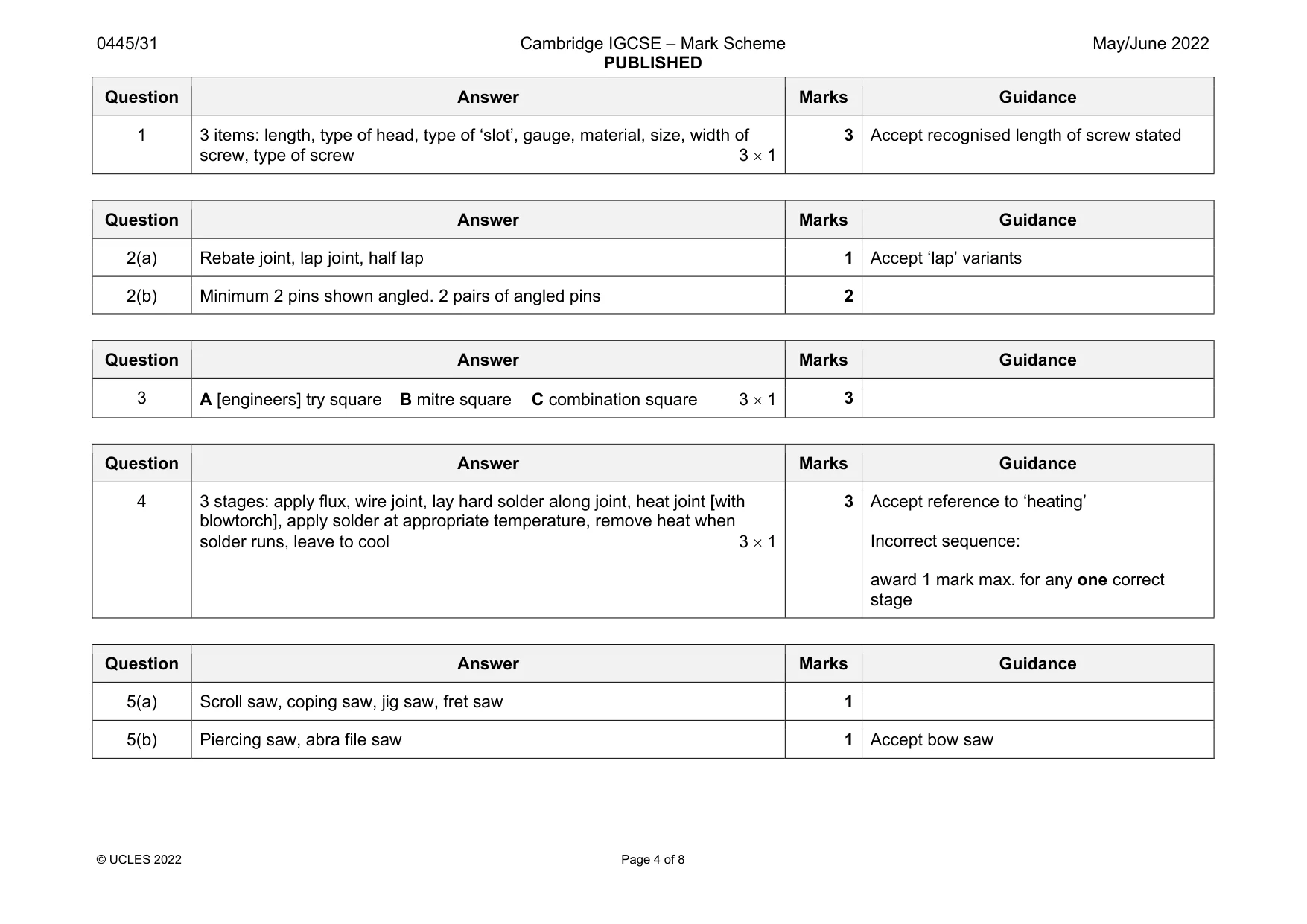
Mark scheme: 1 3 items: length, type of head, type of ‘slot’, gauge, material, size, width of screw, type of screw 3 1 3 Accept recognised length of screw stated
Q2 · Two pieces of softwood glued together
2 Fig. 2.1 shows two pieces of softwood glued together. Fig. 2.1 (a) Name the type of joint shown in Fig. 2.1. ............................................................................................................................................. [1] (b) Add sketches to Fig. 2.1 to show how the joint could be strengthened by dovetail nailing. [2]
Mark scheme: 2(a) Rebate joint, lap joint, half lap 1 Accept ‘lap’ variants 2(b) Minimum 2 pins shown angled. 2 pairs of angled pins 2
Q3 · Three different types of ‘square’, A, B and C, that could be used when marking out and…
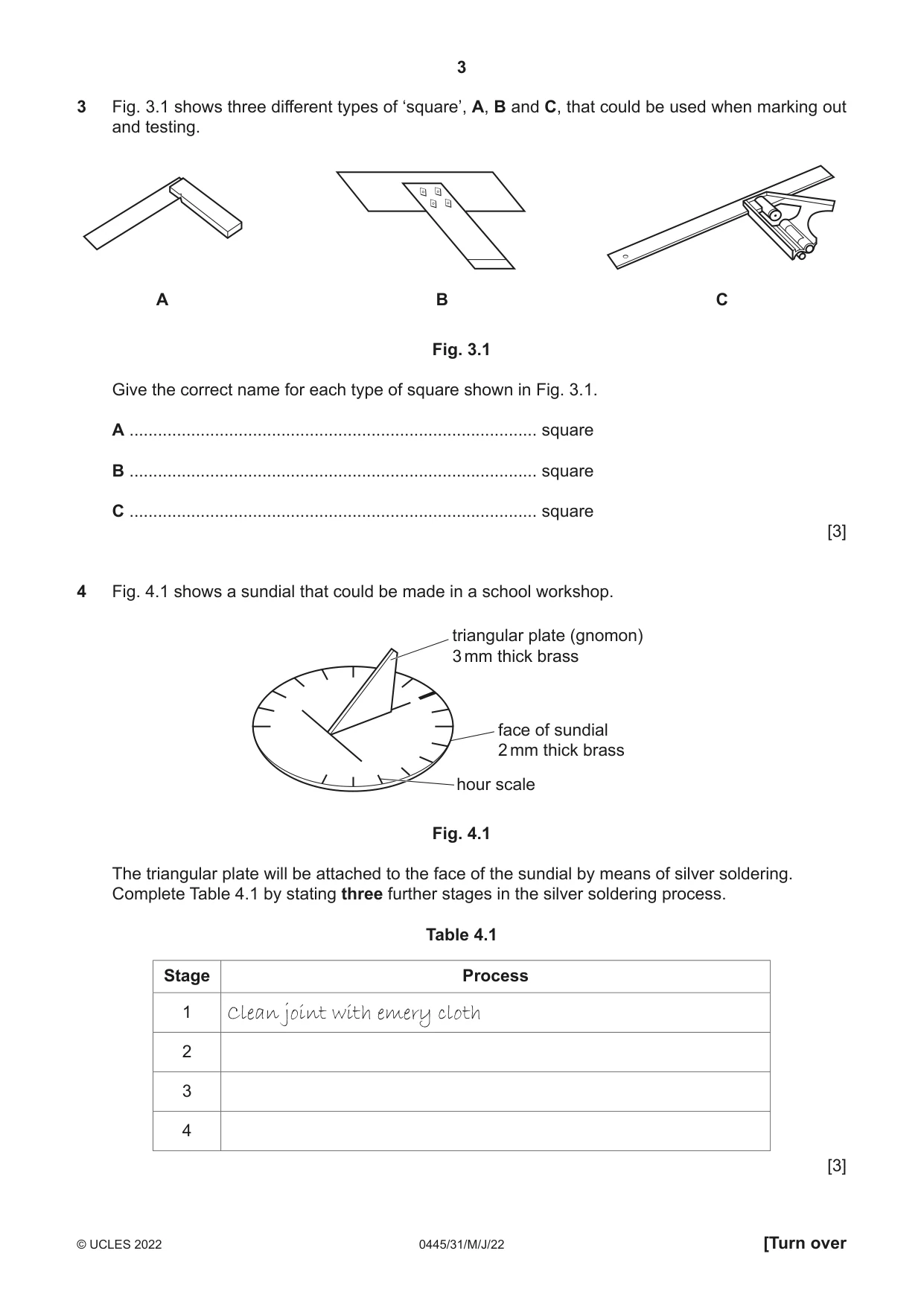
3 Fig. 3.1 shows three different types of ‘square’, A, B and C, that could be used when marking out and testing. A B C Fig. 3.1 Give the correct name for each type of square shown in Fig. 3.1. A ...................................................................................... square B ...................................................................................... square C ...................................................................................... square [3]
Mark scheme: 3 A [engineers] try square B mitre square C combination square 3
Q4 · A sundial that could be made in a school workshop
4 Fig. 4.1 shows a sundial that could be made in a school workshop. triangular plate (gnomon) 3 mm thick brass face of sundial 2 mm thick brass hour scale Fig. 4.1 The triangular plate will be attached to the face of the sundial by means of silver soldering. Complete Table 4.1 by stating three further stages in the silver soldering process. Table 4.1 Stage Process 1 Clean joint with emery cloth 2 3 4 [3]
Mark scheme: 4 3 stages: apply flux, wire joint, lay hard solder along joint, heat joint [with blowtorch], apply solder at appropriate temperature, remove heat when solder runs, leave to cool 3 1 Incorrect sequence: award 1 mark max. for any one correct stage
Q5 · A slot marked out on sheet material
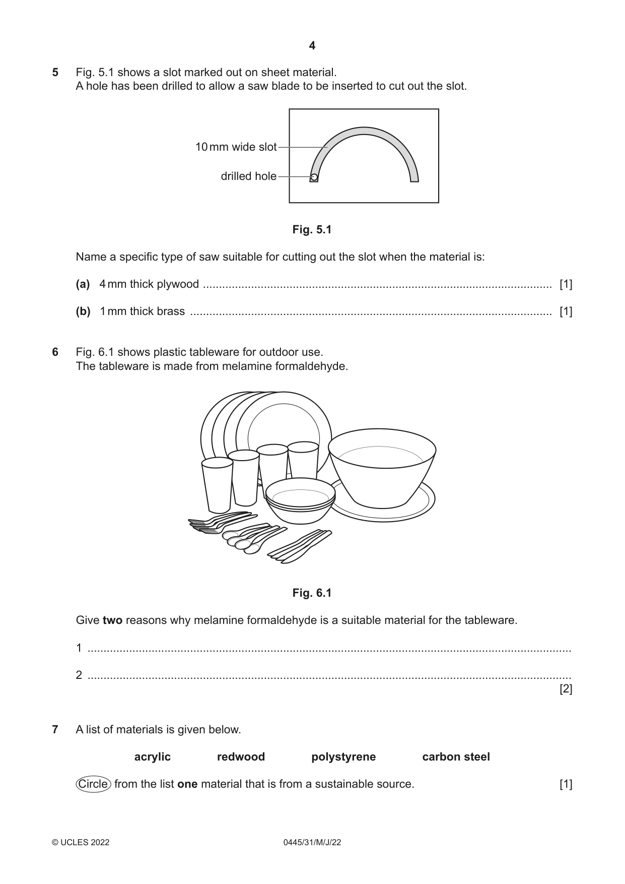
5 Fig. 5.1 shows a slot marked out on sheet material. A hole has been drilled to allow a saw blade to be inserted to cut out the slot. 10 mm wide slot drilled hole Fig. 5.1 Name a specific type of saw suitable for cutting out the slot when the material is: (a) 4 mm thick plywood ............................................................................................................. [1] (b) 1 mm thick brass ................................................................................................................. [1]
Mark scheme: 5(a) Scroll saw, coping saw, jig saw, fret saw 1 5(b) Piercing saw, abra file saw 1 Accept bow saw
Q6 · Plastic tableware for outdoor use
6 Fig. 6.1 shows plastic tableware for outdoor use. The tableware is made from melamine formaldehyde. Fig. 6.1 Give two reasons why melamine formaldehyde is a suitable material for the tableware. 1 ....................................................................................................................................................... 2 ....................................................................................................................................................... [2]
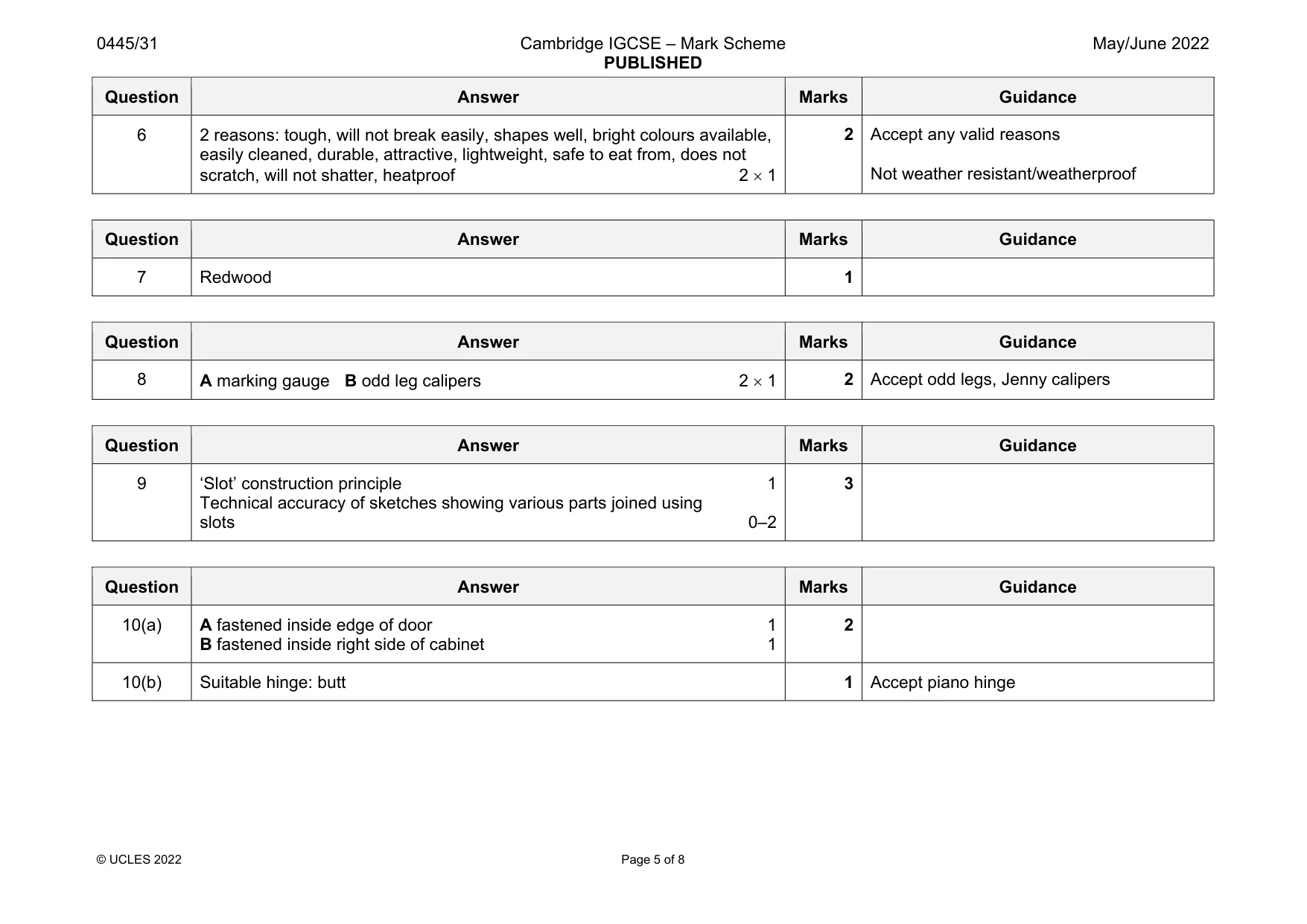
Mark scheme: 6 2 reasons: tough, will not break easily, shapes well, bright colours available, easily cleaned, durable, attractive, lightweight, safe to eat from, does not scratch, will not shatter, heatproof 2 1 Not weather resistant/weatherproof
Q7 · A list of materials is given below
7 A list of materials is given below. acrylic redwood polystyrene carbon steel Circle from the list one material that is from a sustainable source. [1]
Mark scheme: 7 Redwood 1
Q8 · Two tools, A and B, that are used to mark lines parallel to the edges of materials
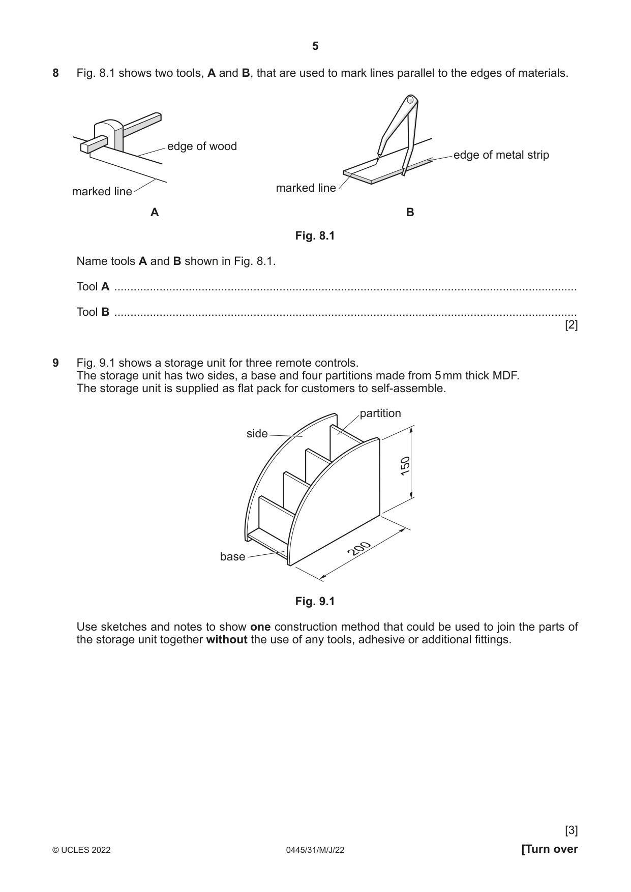
8 Fig. 8.1 shows two tools, A and B, that are used to mark lines parallel to the edges of materials. edge of wood edge of metal strip marked line marked line A B Fig. 8.1 Name tools A and B shown in Fig. 8.1. Tool A ............................................................................................................................................... Tool B ............................................................................................................................................... [2]
Mark scheme: 8 A marking gauge B odd leg calipers 2 Accept odd legs, Jenny calipers
Q9 · A storage unit for three remote controls
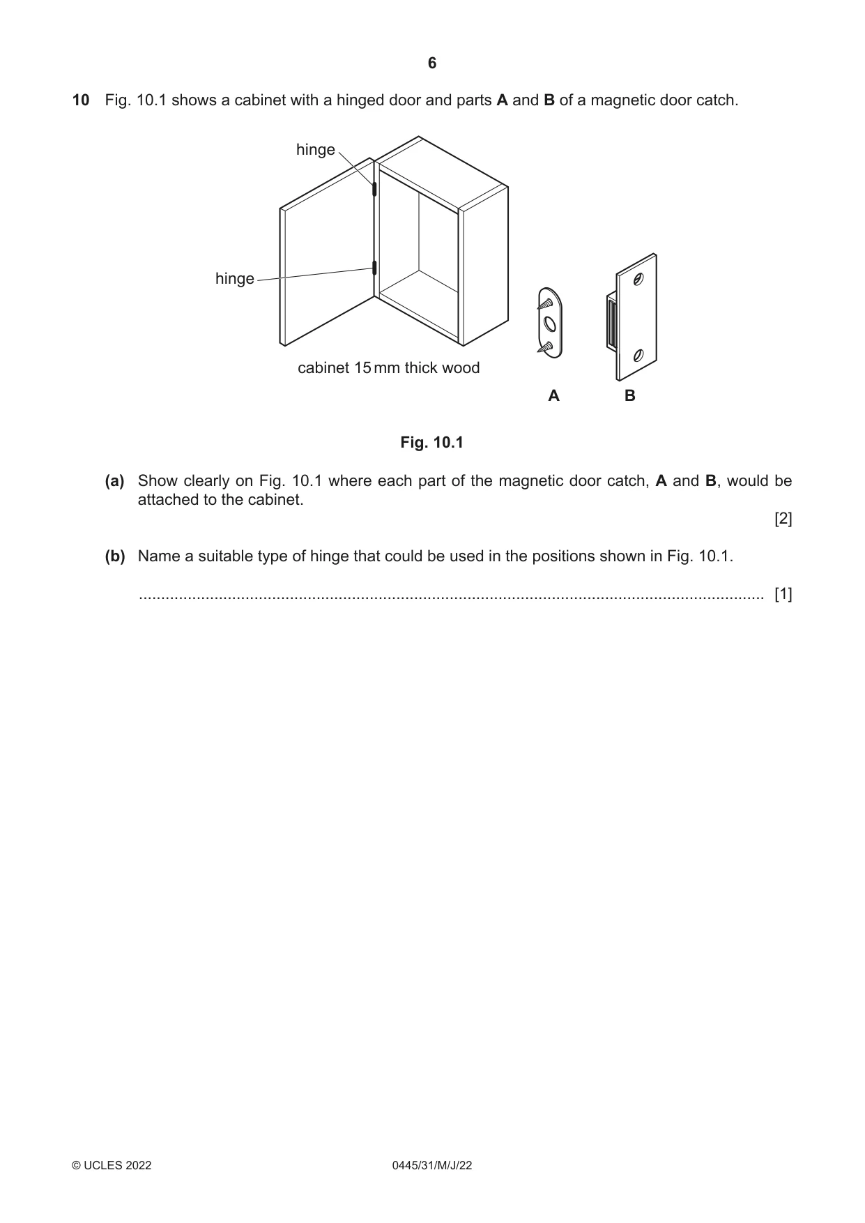
9 Fig. 9.1 shows a storage unit for three remote controls. The storage unit has two sides, a base and four partitions made from 5 mm thick MDF. The storage unit is supplied as flat pack for customers to self-assemble. partition side 150 200 base Fig. 9.1 Use sketches and notes to show one construction method that could be used to join the parts of the storage unit together without the use of any tools, adhesive or additional fittings. [3]
Mark scheme: 9 ‘Slot’ construction principle 1 Technical accuracy of sketches showing various parts joined using slots 0–2 3
Q10 · A cabinet with a hinged door and parts A and B of a magnetic door catch
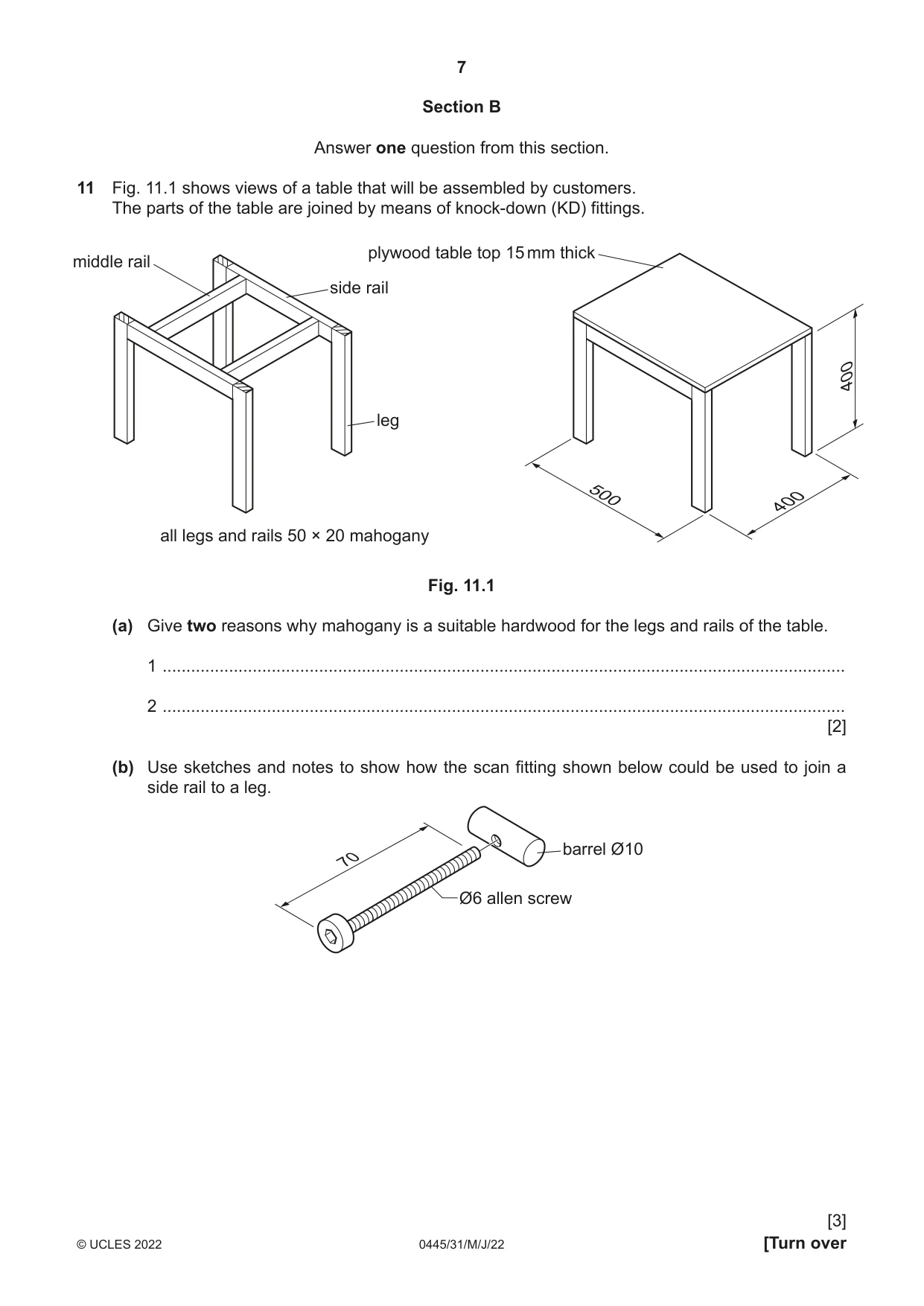
10 Fig. 10.1 shows a cabinet with a hinged door and parts A and B of a magnetic door catch. hinge hinge cabinet 15 mm thick wood A B Fig. 10.1 (a) Show clearly on Fig. 10.1 where each part of the magnetic door catch, A and B, would be attached to the cabinet. [2] (b) Name a suitable type of hinge that could be used in the positions shown in Fig. 10.1. ............................................................................................................................................. [1]
Mark scheme: 10(a) A fastened inside edge of door 1 B fastened inside right side of cabinet 1 2 10(b) Suitable hinge: butt 1 Accept piano hinge
Q11 · Views of a table that will be assembled by customers
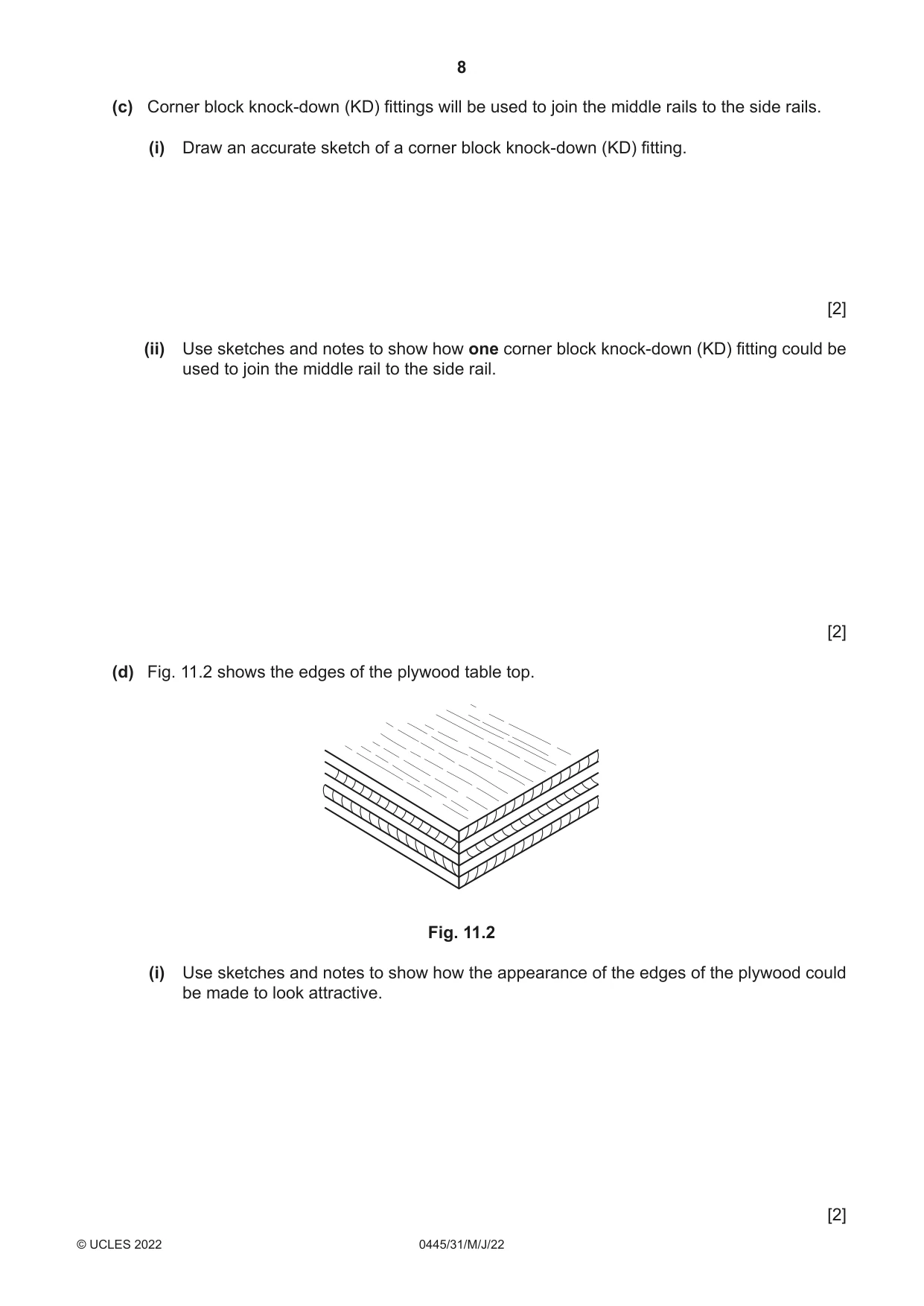
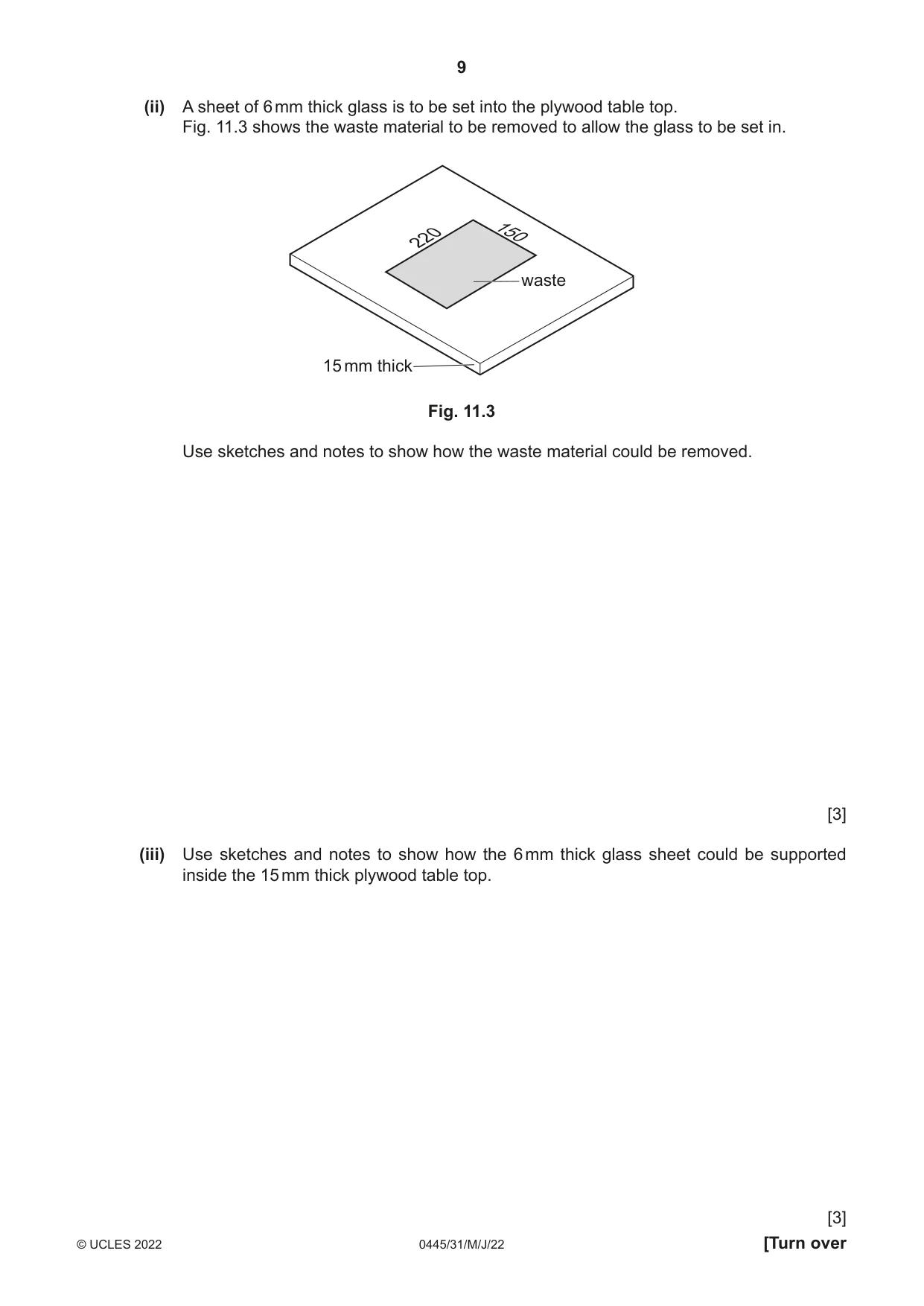
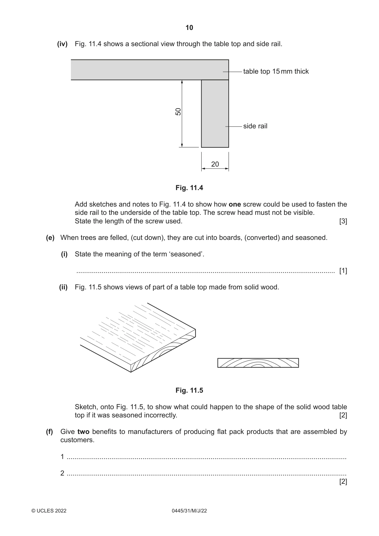
11 Fig. 11.1 shows views of a table that will be assembled by customers. The parts of the table are joined by means of knock-down (KD) fittings. plywood table top 15 mm thickmiddle rail side rail 400 leg 500 400 all legs and rails 50 × 20 mahogany Fig. 11.1 (a) Give two reasons why mahogany is a suitable hardwood for the legs and rails of the table. 1 ................................................................................................................................................ 2 ................................................................................................................................................ [2] (b) Use sketches and notes to show how the scan fitting shown below could be used to join a side rail to a leg. barrel Ø10 70 Ø6 allen screw [3] (c) Corner block knock-down (KD) fittings will be used to join the middle rails to the side rails. (i) Draw an accurate sketch of a corner block knock-down (KD) fitting. [2] (ii) Use sketches and notes to show how one corner block knock-down (KD) fitting could be used to join the middle rail to the side rail. [2] (d) Fig. 11.2 shows the edges of the plywood table top. Fig. 11.2 (i) Use sketches and notes to show how the appearance of the edges of the plywood could be made to look attractive. [2] (ii) A sheet of 6 mm thick glass is to be set into the plywood table top. Fig. 11.3 shows the waste material to be removed to allow the glass to be set in. 150 220 waste 15 mm thick Fig. 11.3 Use sketches and notes to show how the waste material could be removed. [3] (iii) Use sketches and notes to show how the 6 mm thick glass sheet could be supported inside the 15 mm thick plywood table top. [3] (iv) Fig. 11.4 shows a sectional view through the table top and side rail. table top 15 mm thick 50 side rail 20 Fig. 11.4 Add sketches and notes to Fig. 11.4 to show how one screw could be used to fasten the side rail to the underside of the table top. The screw head must not be visible. State the length of the screw used. [3] (e) When trees are felled, (cut down), they are cut into boards, (converted) and seasoned. (i) State the meaning of the term ‘seasoned’. ..................................................................................................................................... [1] (ii) Fig. 11.5 shows views of part of a table top made from solid wood. Fig. 11.5 Sketch, onto Fig. 11.5, to show what could happen to the shape of the solid wood table top if it was seasoned incorrectly. [2] (f) Give two benefits to manufacturers of producing flat pack products that are assembled by customers. 1 ................................................................................................................................................ 2 ................................................................................................................................................ [2]
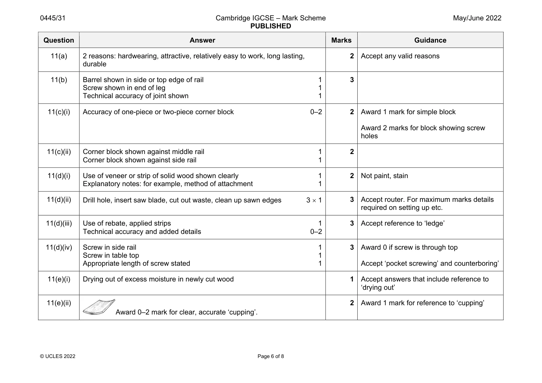
Mark scheme: 11(a) 2 reasons: hardwearing, attractive, relatively easy to work, long lasting, durable 2 Accept any valid reasons 11(b) Barrel shown in side or top edge of rail 1 Screw shown in end of leg 1 Technical accuracy of joint shown 1 3 11(c)(i) Accuracy of one-piece or two-piece corner block 0–2 2 Award 1 mark for simple block Award 2 marks for block showing screw holes 11(c)(ii) Corner block shown against middle rail 1 Corner block shown against side rail 1 2 11(d)(i) Use of veneer or strip of solid wood shown clearly 1 Explanatory notes: for example, method of attachment 1 2 Not paint, stain 11(d)(ii) Drill hole, insert saw blade, cut out waste, clean up sawn edges 3 1 3 Accept router. For maximum marks details required on setting up etc. 11(d)(iii) Use of rebate, applied strips 1 Technical accuracy and added details 0–2 3 Accept reference to ‘ledge’ 11(d)(iv) Screw in side rail 1 Screw in table top 1 Appropriate length of screw stated 1 3 Award 0 if screw is through top Accept ‘pocket screwing’ and counterboring’ 11(e)(i) Drying out of excess moisture in newly cut wood 1 Accept answers that include reference to ‘drying out’ 11(e)(ii) Award 0–2 mark for clear, accurate ‘cupping’. 2 Award 1 mark for reference to ‘cupping’ Question Answer Marks Guidance 11(f) 2 benefits to manufacturers: no assembly required, less labour costs, reduced prices passed on to customers, less storage space required, reduced transport costs, easier to manufacture, less packaging 2 1 2 Accept any valid benefits Cheaper + justification
Q12 · Details of a desktop toy
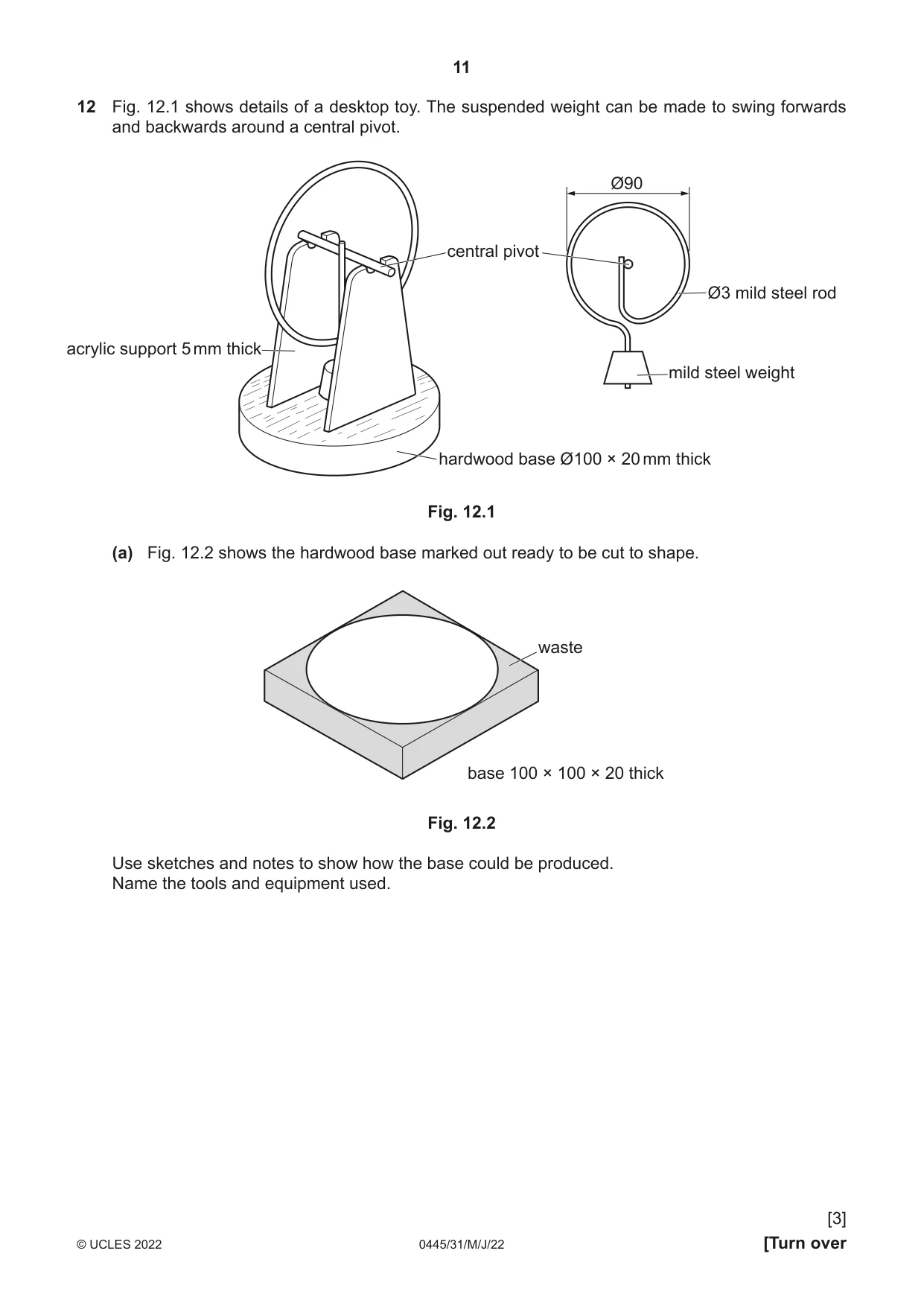
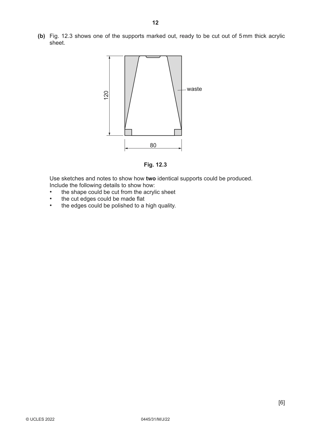
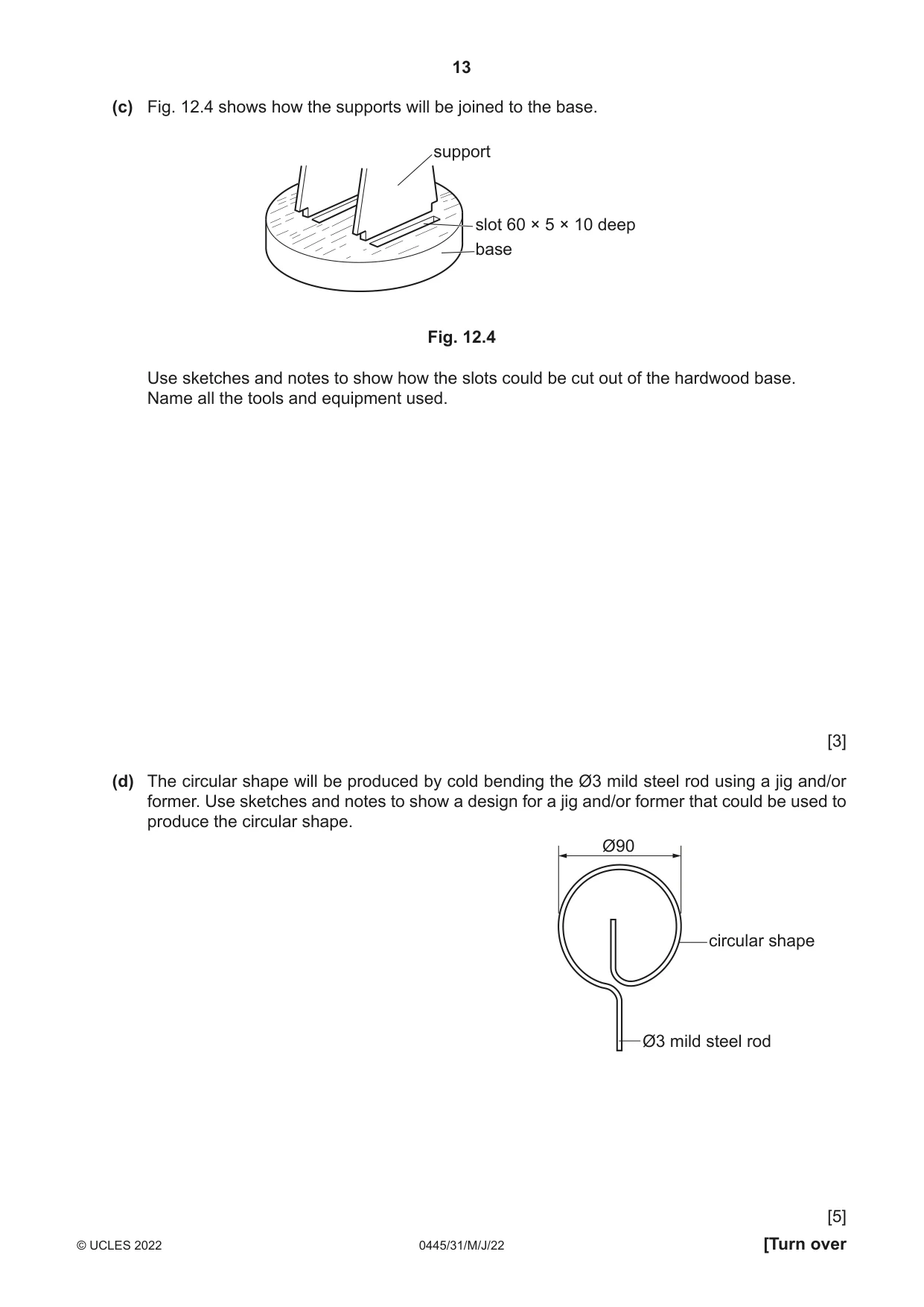
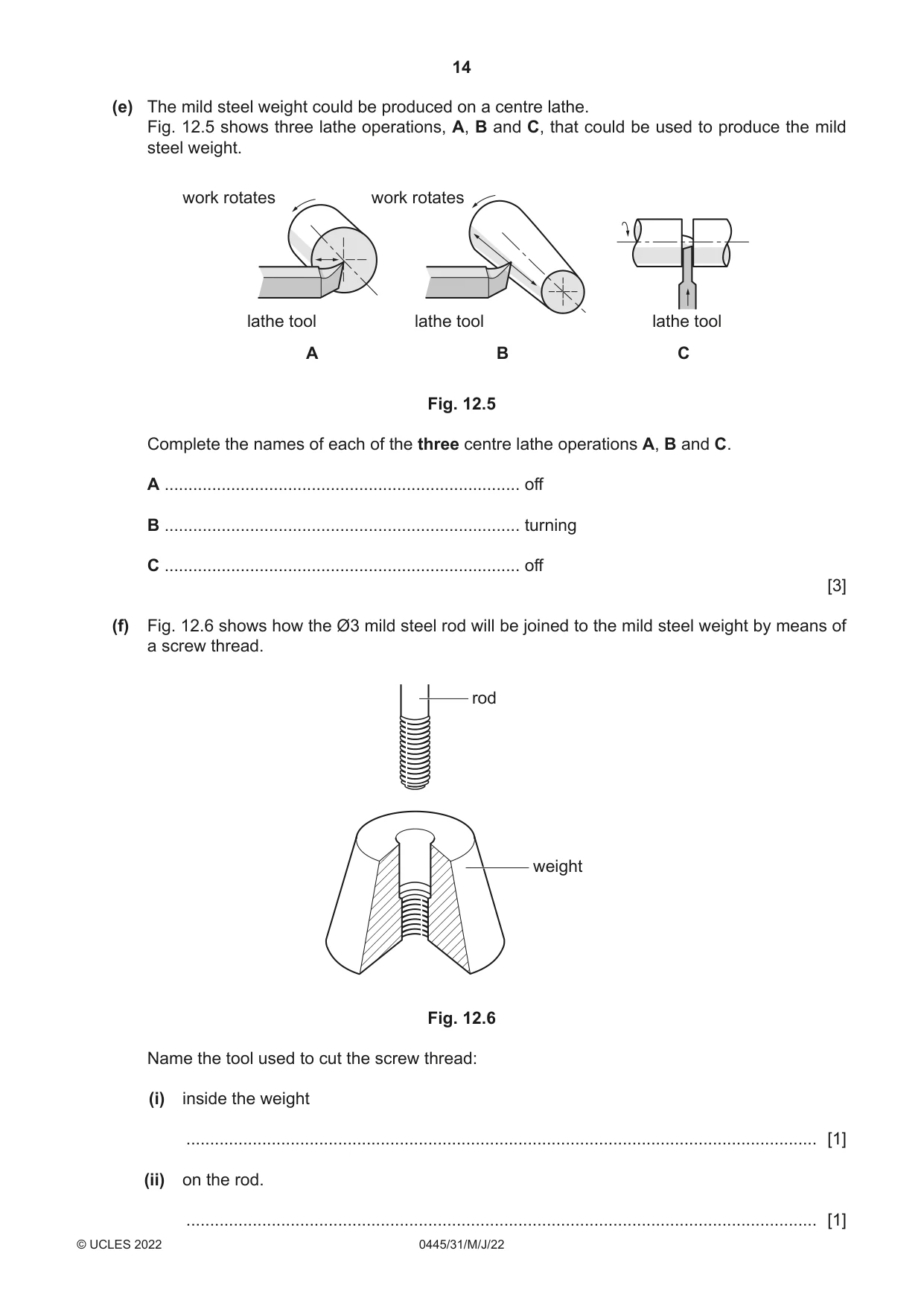
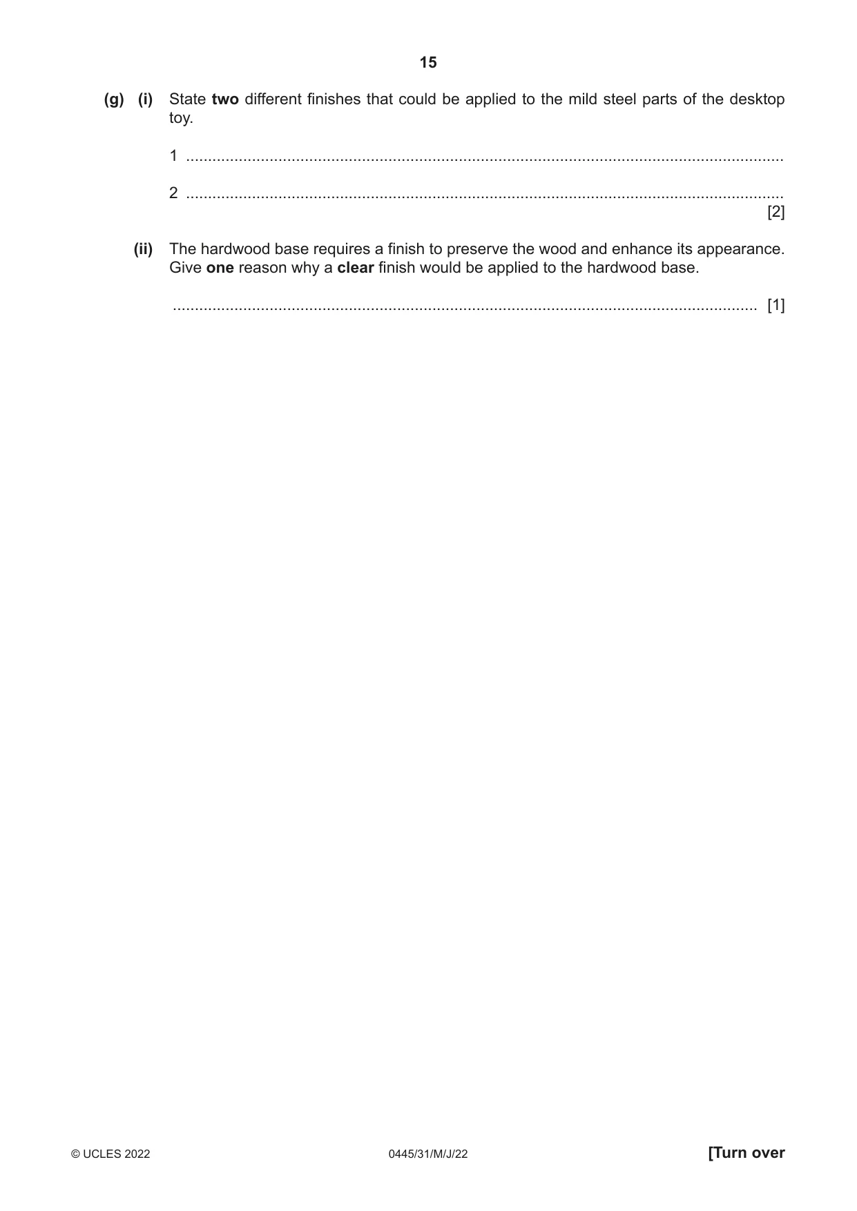
12 Fig. 12.1 shows details of a desktop toy. The suspended weight can be made to swing forwards and backwards around a central pivot. Ø90 central pivot Ø3 mild steel rod acrylic support 5 mm thick mild steel weight hardwood base Ø100 × 20 mm thick Fig. 12.1 (a) Fig. 12.2 shows the hardwood base marked out ready to be cut to shape. waste base 100 × 100 × 20 thick Fig. 12.2 Use sketches and notes to show how the base could be produced. Name the tools and equipment used. [3] (b) Fig. 12.3 shows one of the supports marked out, ready to be cut out of 5 mm thick acrylic sheet. waste 120 80 Fig. 12.3 Use sketches and notes to show how two identical supports could be produced. Include the following details to show how: • the shape could be cut from the acrylic sheet • the cut edges could be made flat • the edges could be polished to a high quality. [6] (c) Fig. 12.4 shows how the supports will be joined to the base. support slot 60 × 5 × 10 deep base Fig. 12.4 Use sketches and notes to show how the slots could be cut out of the hardwood base. Name all the tools and equipment used. [3] (d) The circular shape will be produced by cold bending the Ø3 mild steel rod using a jig and/or former. Use sketches and notes to show a design for a jig and/or former that could be used to produce the circular shape. Ø90 circular shape Ø3 mild steel rod [5] (e) The mild steel weight could be produced on a centre lathe. Fig. 12.5 shows three lathe operations, A, B and C, that could be used to produce the mild steel weight. work rotates work rotates lathe tool lathe tool lathe tool A B C Fig. 12.5 Complete the names of each of the three centre lathe operations A, B and C. A ........................................................................... off B ........................................................................... turning C ........................................................................... off [3] (f) Fig. 12.6 shows how the Ø3 mild steel rod will be joined to the mild steel weight by means of a screw thread. rod weight Fig. 12.6 Name the tool used to cut the screw thread: (i) inside the weight ..................................................................................................................................... [1] (ii) on the rod. ..................................................................................................................................... [1] (g) (i) State two different finishes that could be applied to the mild steel parts of the desktop toy. 1 ........................................................................................................................................ 2 ........................................................................................................................................ [2] (ii) The hardwood base requires a finish to preserve the wood and enhance its appearance. Give one reason why a clear finish would be applied to the hardwood base. ..................................................................................................................................... [1]
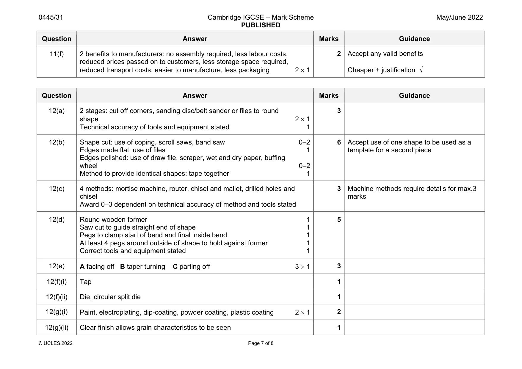
Mark scheme: 12(a) 2 stages: cut off corners, sanding disc/belt sander or files to round shape 2 1 Technical accuracy of tools and equipment stated 1 12(b) Shape cut: use of coping, scroll saws, band saw 0–2 Edges made flat: use of files 1 Edges polished: use of draw file, scraper, wet and dry paper, buffing wheel 0–2 Method to provide identical shapes: tape together 1 6 Accept use of one shape to be used as a template for a second piece 12(c) 4 methods: mortise machine, router, chisel and mallet, drilled holes and chisel Award 0–3 dependent on technical accuracy of method and tools stated 3 Machine methods require details for max.3 marks 12(d) Round wooden former 1 Saw cut to guide straight end of shape 1 Pegs to clamp start of bend and final inside bend 1 At least 4 pegs around outside of shape to hold against former 1 Correct tools and equipment stated 1 5 12(e) A facing off B taper turning C parting off 3 1 3 12(f)(i) Tap 1 12(f)(ii) Die, circular split die 1 12(g)(i) Paint, electroplating, dip-coating, powder coating, plastic coating 2 1 2 12(g)(ii) Clear finish allows grain characteristics to be seen 1
Q13 · An incomplete design for a wind gauge that could be made in a school workshop
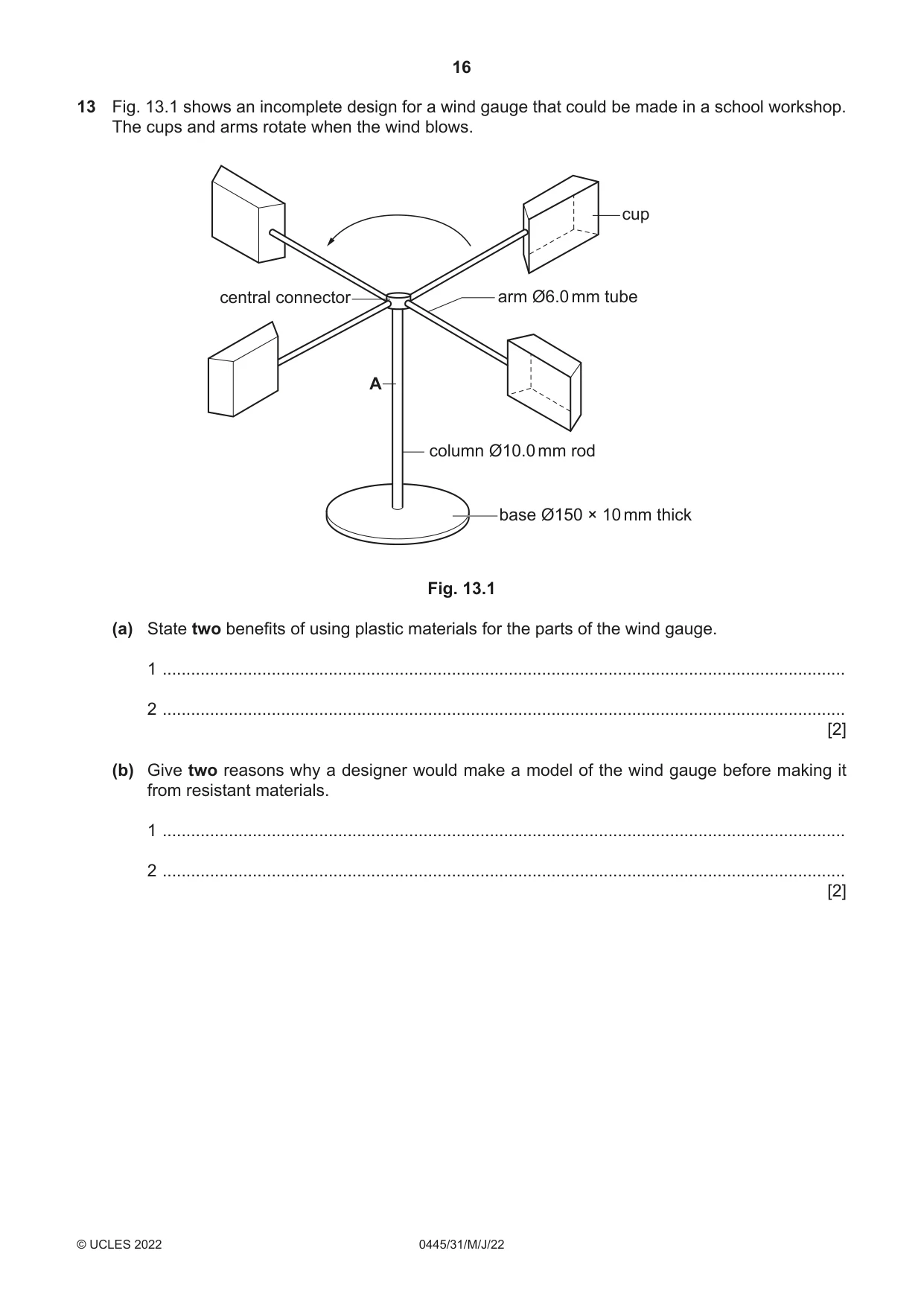
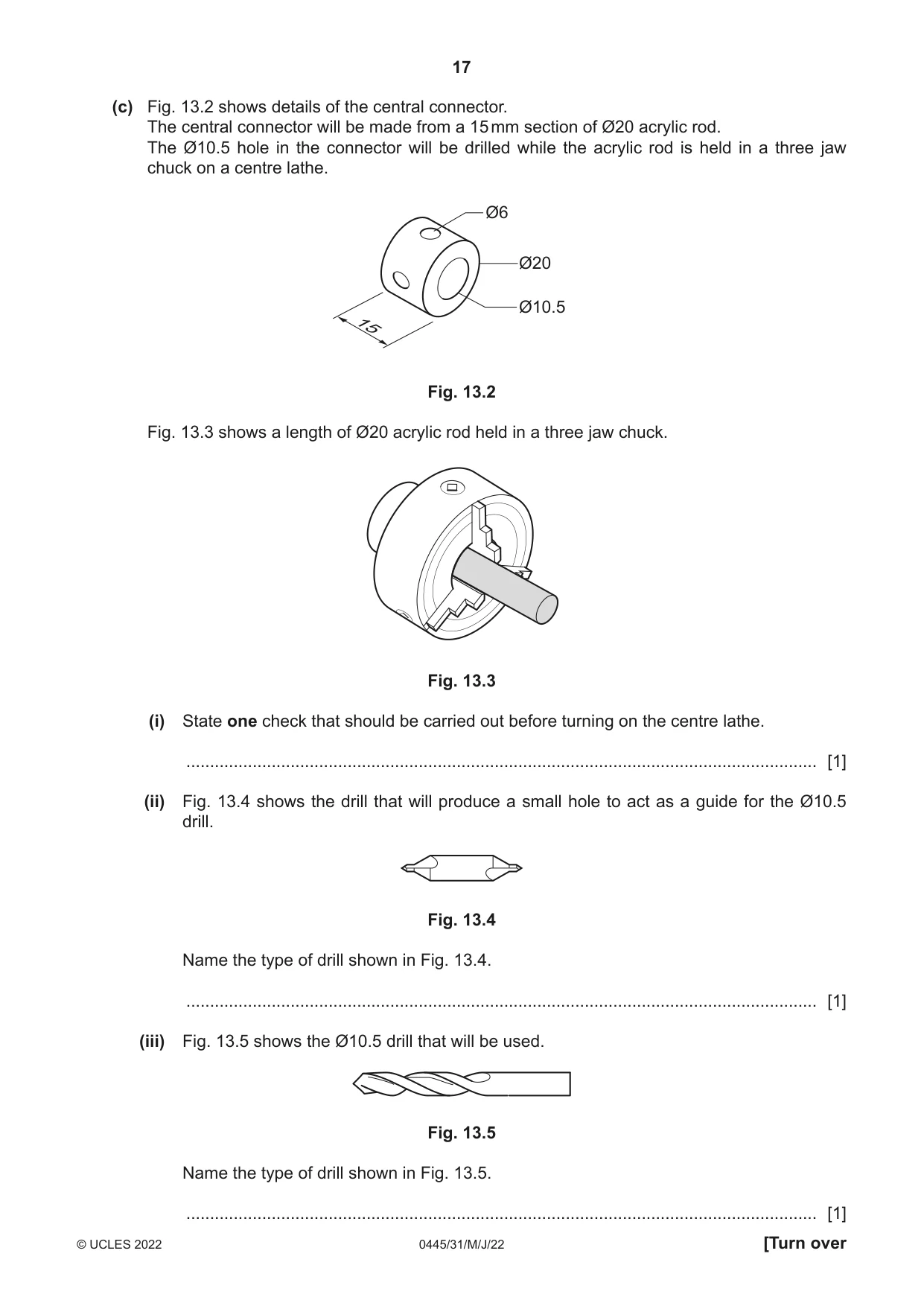
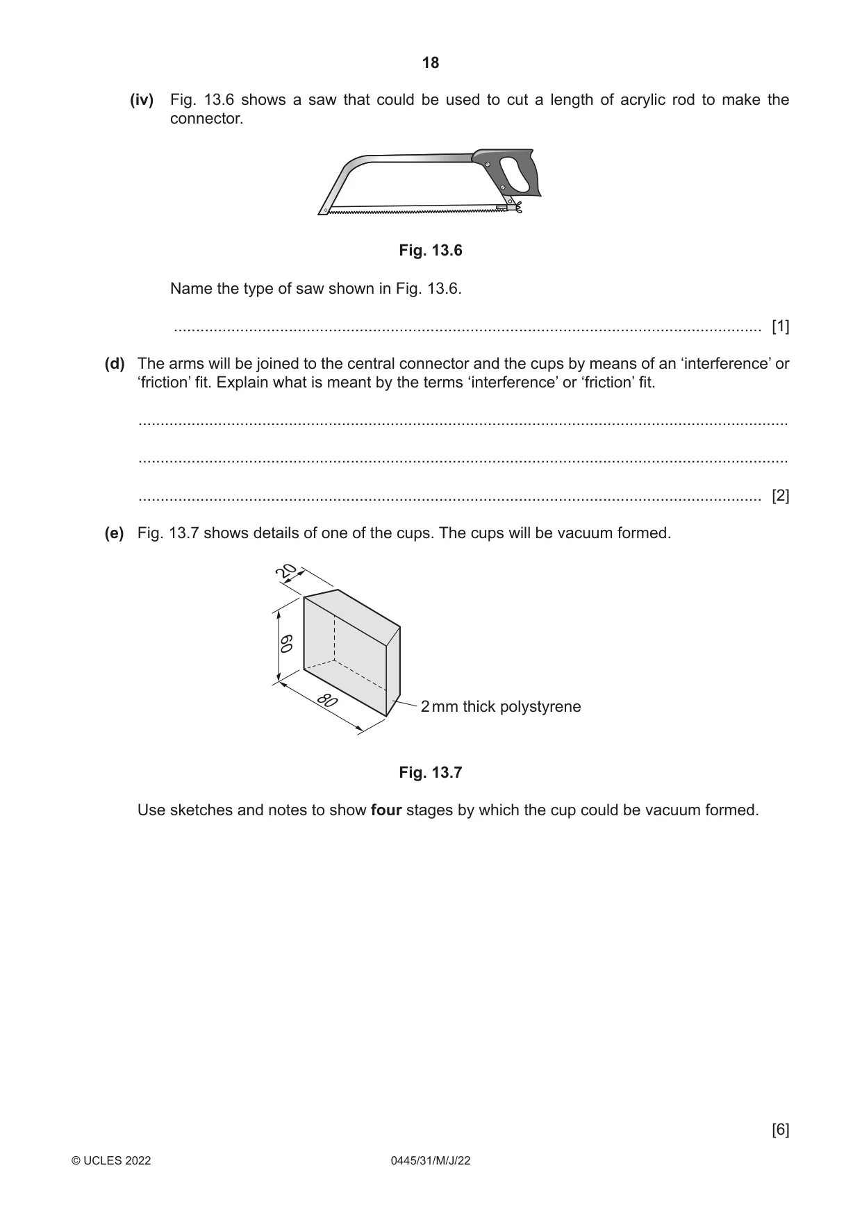
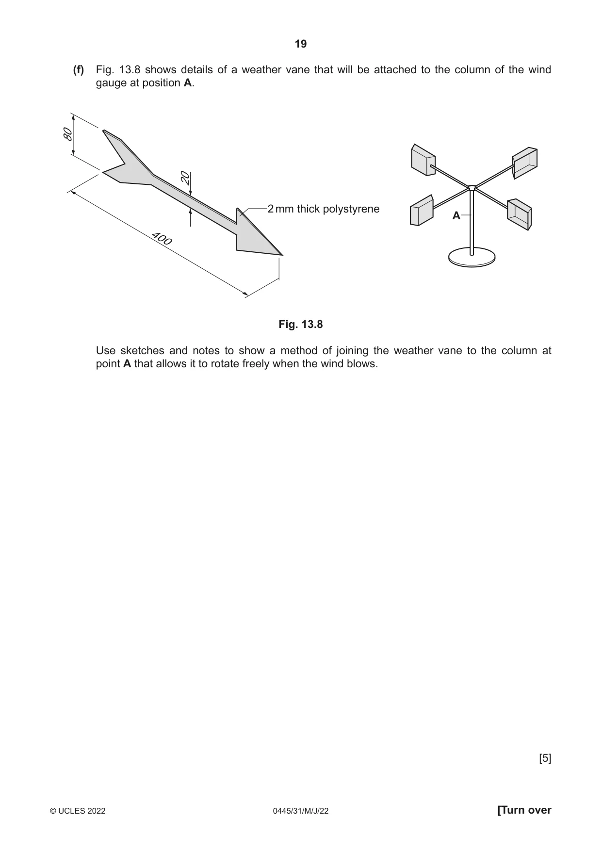
13 Fig. 13.1 shows an incomplete design for a wind gauge that could be made in a school workshop. The cups and arms rotate when the wind blows. cup central connector arm Ø6.0 mm tube A column Ø10.0 mm rod base Ø150 × 10 mm thick Fig. 13.1 (a) State two benefits of using plastic materials for the parts of the wind gauge. 1 ................................................................................................................................................ 2 ................................................................................................................................................ [2] (b) Give two reasons why a designer would make a model of the wind gauge before making it from resistant materials. 1 ................................................................................................................................................ 2 ................................................................................................................................................ [2] (c) Fig. 13.2 shows details of the central connector. The central connector will be made from a 15 mm section of Ø20 acrylic rod. The Ø10.5 hole in the connector will be drilled while the acrylic rod is held in a three jaw chuck on a centre lathe. Ø6 Ø20 Ø10.5 15 Fig. 13.2 Fig. 13.3 shows a length of Ø20 acrylic rod held in a three jaw chuck. Fig. 13.3 (i) State one check that should be carried out before turning on the centre lathe. ..................................................................................................................................... [1] (ii) Fig. 13.4 shows the drill that will produce a small hole to act as a guide for the Ø10.5 drill. Fig. 13.4 Name the type of drill shown in Fig. 13.4. ..................................................................................................................................... [1] (iii) Fig. 13.5 shows the Ø10.5 drill that will be used. Fig. 13.5 Name the type of drill shown in Fig. 13.5. ..................................................................................................................................... [1] (iv) Fig. 13.6 shows a saw that could be used to cut a length of acrylic rod to make the connector. Fig. 13.6 Name the type of saw shown in Fig. 13.6. ..................................................................................................................................... [1] (d) The arms will be joined to the central connector and the cups by means of an ‘interference’ or ‘friction’ fit. Explain what is meant by the terms ‘interference’ or ‘friction’ fit. ................................................................................................................................................... ................................................................................................................................................... ............................................................................................................................................. [2] (e) Fig. 13.7 shows details of one of the cups. The cups will be vacuum formed. 20 60 80 2 mm thick polystyrene Fig. 13.7 Use sketches and notes to show four stages by which the cup could be vacuum formed. [6]
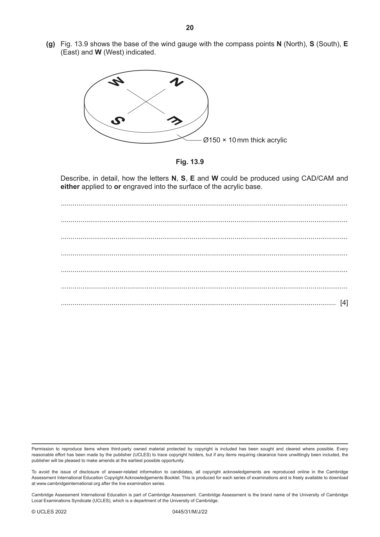
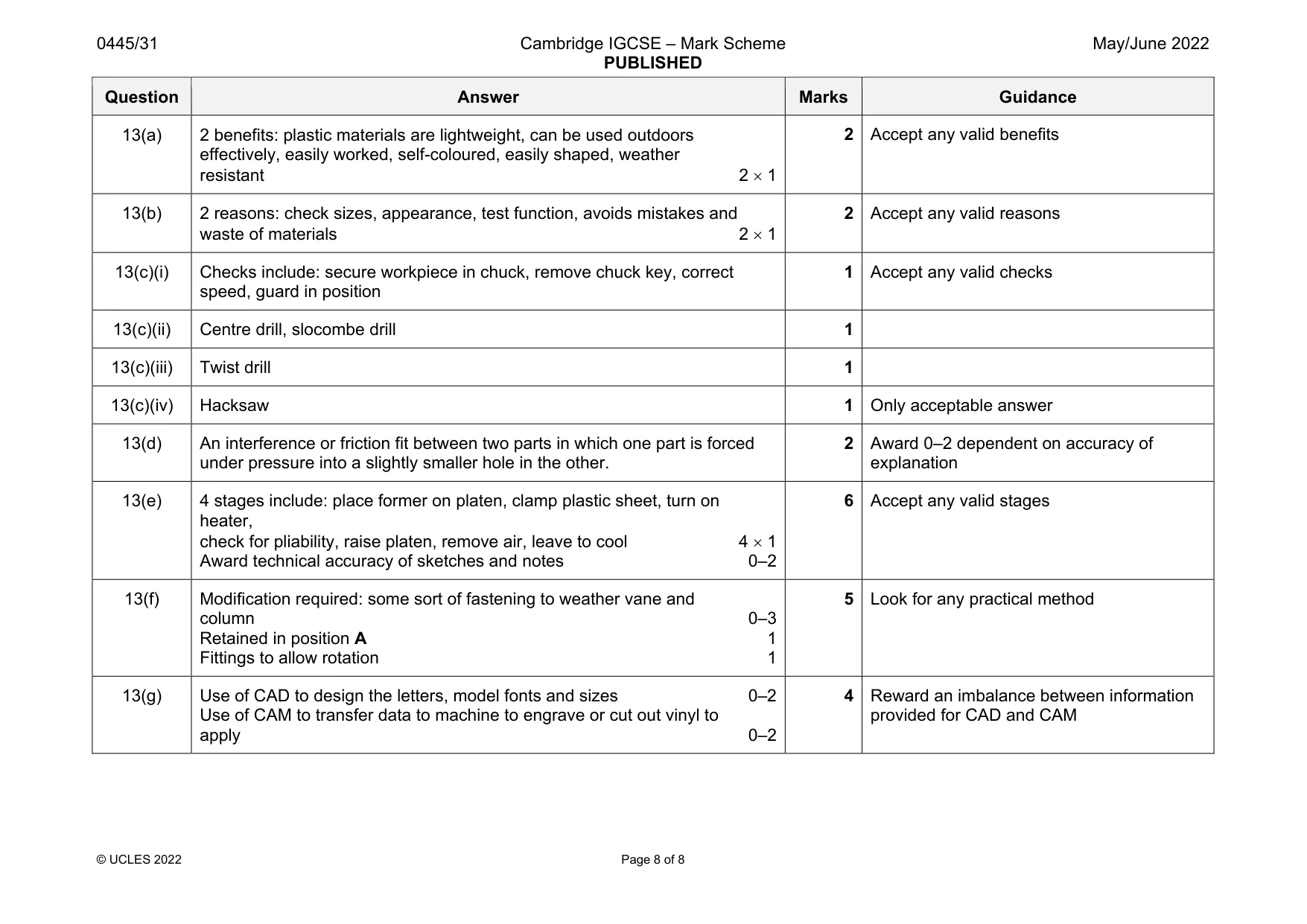
Mark scheme: 13(a) 2 benefits: plastic materials are lightweight, can be used outdoors effectively, easily worked, self-coloured, easily shaped, weather resistant 2 1 13(b) 2 reasons: check sizes, appearance, test function, avoids mistakes and waste of materials 2 1 2 Accept any valid reasons 13(c)(i) Checks include: secure workpiece in chuck, remove chuck key, correct speed, guard in position 1 Accept any valid checks 13(c)(ii) Centre drill, slocombe drill 1 13(c)(iii) Twist drill 1 13(c)(iv) Hacksaw 1 Only acceptable answer 13(d) An interference or friction fit between two parts in which one part is forced under pressure into a slightly smaller hole in the other. 2 Award 0–2 dependent on accuracy of explanation 13(e) 4 stages include: place former on platen, clamp plastic sheet, turn on heater, check for pliability, raise platen, remove air, leave to cool 4 1 Award technical accuracy of sketches and notes 0–2 6 Accept any valid stages 13(f) Modification required: some sort of fastening to weather vane and column 0–3 Retained in position A 1 Fittings to allow rotation 1 5 Look for any practical method 13(g) Use of CAD to design the letters, model fonts and sizes 0–2 Use of CAM to transfer data to machine to engrave or cut out vinyl to apply 0–2 4 Reward an imbalance between information provided for CAD and CAM
What was in this paper
The subtopics covered by these 13 questions, and how many questions each got. Open one in a new tab to see every Cambridge question on it.
What you needed in this session
Cambridge’s own grade thresholds for 2022 May/June, Paper 3 · Variant 1. A higher threshold means an easier paper — the bar moves with how the cohort did.