Cambridge IGCSE Design and Technology 0445 — 2022 May/June Paper 3 · Variant 3
0445/33/M/J/22 · 13 questions · 50 marks · ≈56 min
The question paper and its mark scheme, free to read here and free to download. This is Cambridge’s own paper, exactly as it was sat.
Question paper20 pages
Mark scheme9 pages
Answers below. Sit the paper first if you are practising.
Questions as text
Q1 · Building blocks used in a children’s construction set
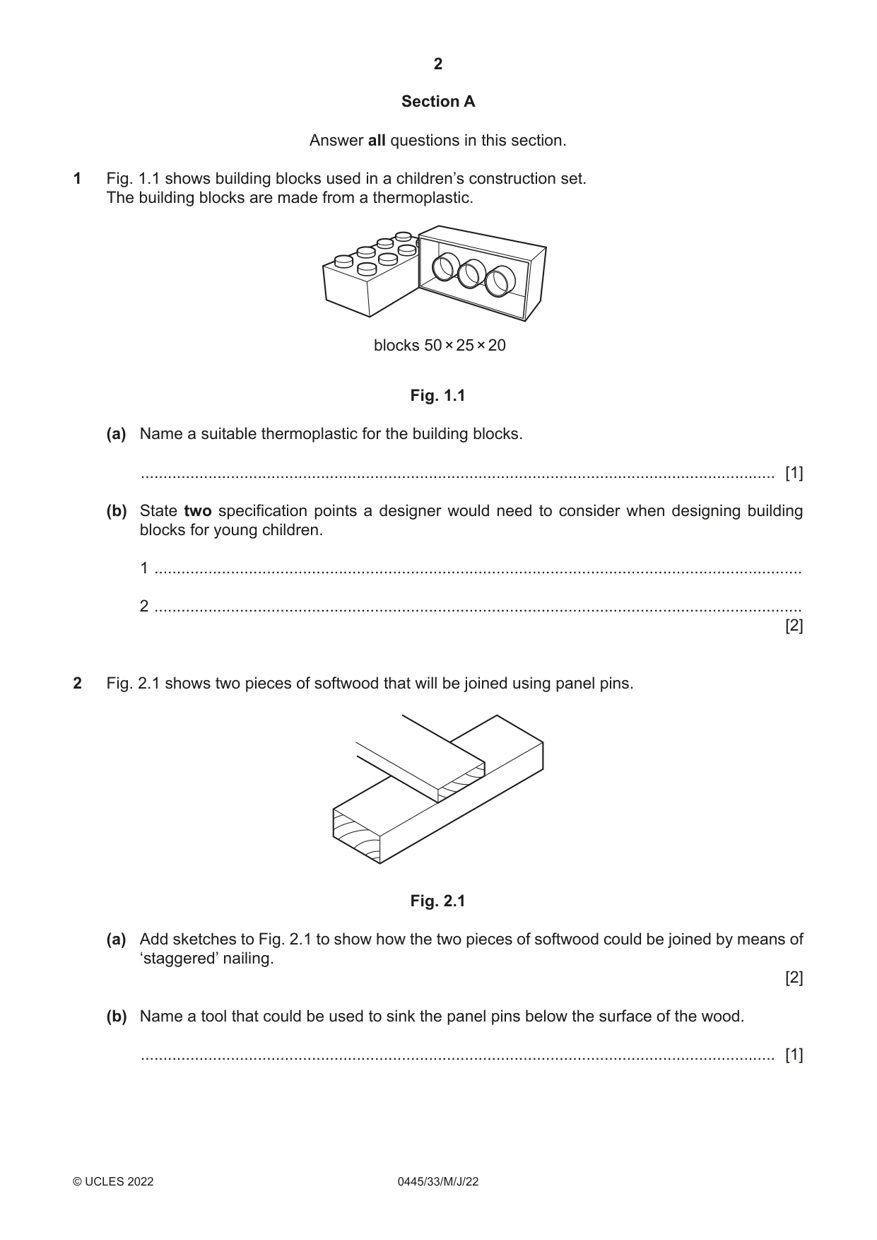
1 Fig. 1.1 shows building blocks used in a children’s construction set. The building blocks are made from a thermoplastic. blocks 50 × 25 × 20 Fig. 1.1 (a) Name a suitable thermoplastic for the building blocks. ............................................................................................................................................. [1] (b) State two specification points a designer would need to consider when designing building blocks for young children. 1 ................................................................................................................................................ 2 ................................................................................................................................................ [2]
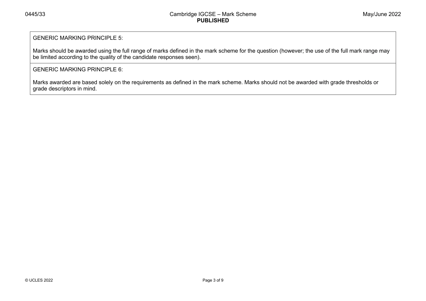
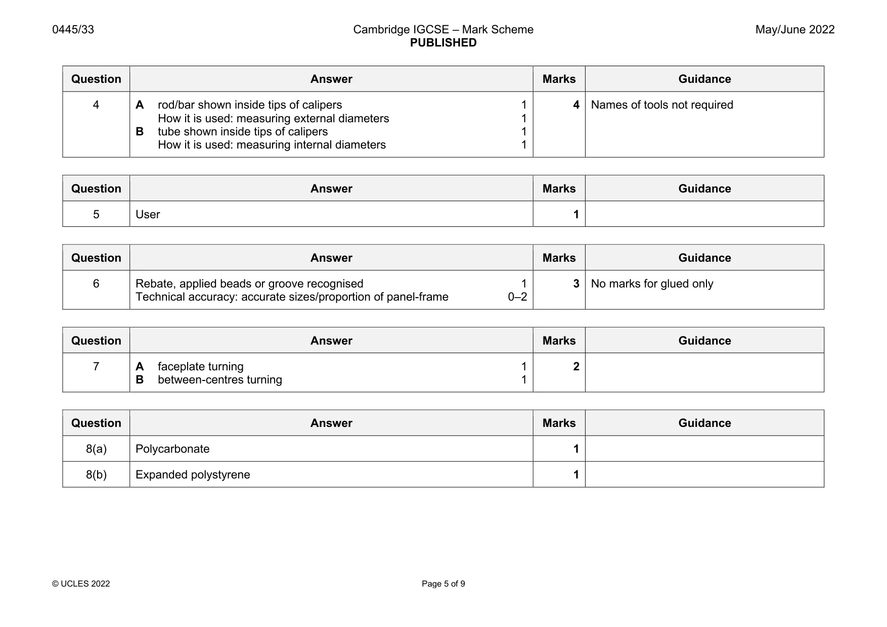
Mark scheme: Question Answer Marks Guidance 1(a) ABS, PP, PETE, PET, HDPE, HIPS 1 Not PVC, Acrylic, Polystyrene, Polyethene, Polyethylene 1(b) 2 spec. points: colourful, lightweight, smooth finish, ability to make rounded 2 Accept any valid spec. points corners/edges, non-toxic material, safe/suitable sizes, easy to clean, aesthetics, durable, water resistant
Q2 · Two pieces of softwood that will be joined using panel pins
2 Fig. 2.1 shows two pieces of softwood that will be joined using panel pins. Fig. 2.1 (a) Add sketches to Fig. 2.1 to show how the two pieces of softwood could be joined by means of ‘staggered’ nailing. [2] (b) Name a tool that could be used to sink the panel pins below the surface of the wood. ............................................................................................................................................. [1]
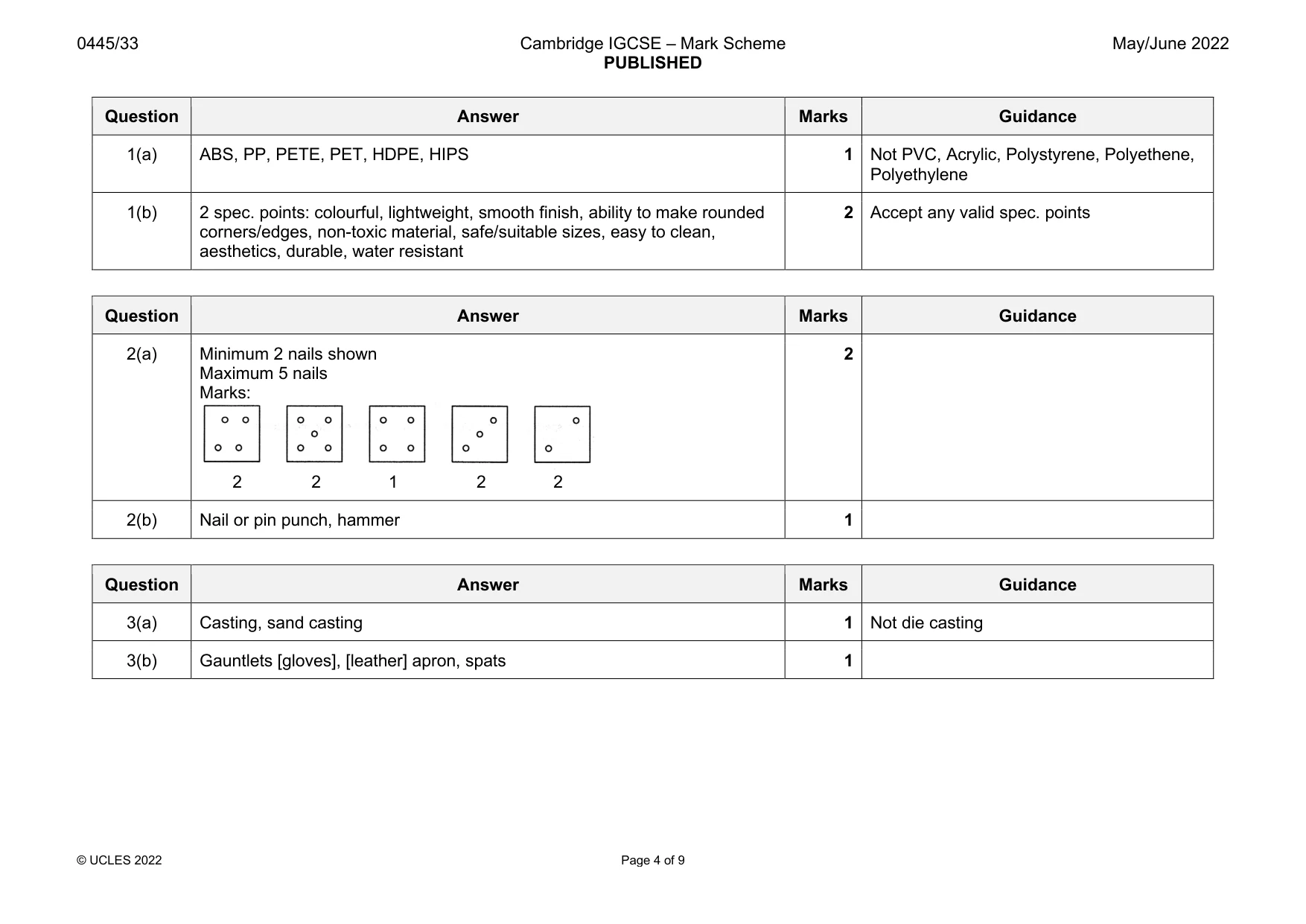
Mark scheme: 2(a) Minimum 2 nails shown 2 Maximum 5 nails Marks: 2 2 1 2 2 2(b) Nail or pin punch, hammer 1
Question 3
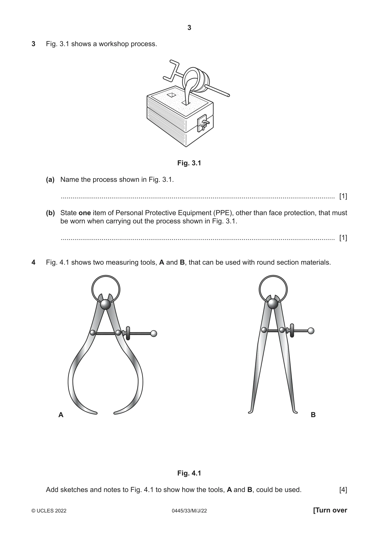
3 Fig. 3.1 shows a workshop process. Fig. 3.1 (a) Name the process shown in Fig. 3.1. ............................................................................................................................................. [1] (b) State one item of Personal Protective Equipment (PPE), other than face protection, that must be worn when carrying out the process shown in Fig. 3.1. ............................................................................................................................................. [1]
Mark scheme: 3(a) Casting, sand casting 1 Not die casting 3(b) Gauntlets [gloves], [leather] apron, spats 1
Q4 · Two measuring tools, A and B, that can be used with round section materials
4 Fig. 4.1 shows two measuring tools, A and B, that can be used with round section materials. A B Fig. 4.1 Add sketches and notes to Fig. 4.1 to show how the tools, A and B, could be used. [4]
Mark scheme: 4 A rod/bar shown inside tips of calipers 1 4 Names of tools not required How it is used: measuring external diameters 1 B tube shown inside tips of calipers 1 How it is used: measuring internal diameters 1
Q5 · Complete the sentence below by adding the correct term from the list
5 Complete the sentence below by adding the correct term from the list. construction user packaging cost Ergonomics is the term given to describe the relationship between a product and its .................................................................................................................................................... [1]
Mark scheme: 5 User 1
Question 6
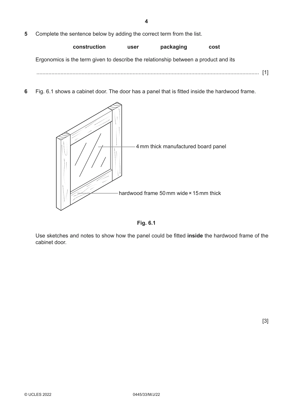
6 Fig. 6.1 shows a cabinet door. The door has a panel that is fitted inside the hardwood frame. 4 mm thick manufactured board panel hardwood frame 50 mm wide × 15 mm thick Fig. 6.1 Use sketches and notes to show how the panel could be fitted inside the hardwood frame of the cabinet door. [3]
Mark scheme: 6 Rebate, applied beads or groove recognised 1 3 No marks for glued only Technical accuracy: accurate sizes/proportion of panel-frame 0–2
Q7 · Two pieces of hardwood, A and B, set up, ready to be ‘turned’ on a woodturning lathe
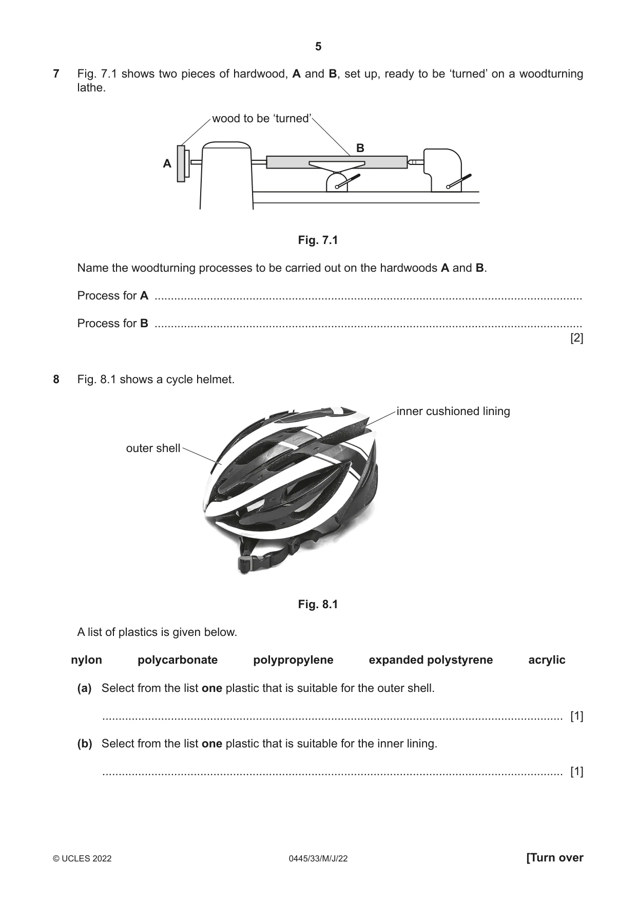
7 Fig. 7.1 shows two pieces of hardwood, A and B, set up, ready to be ‘turned’ on a woodturning lathe. wood to be ‘turned’ B A Fig. 7.1 Name the woodturning processes to be carried out on the hardwoods A and B. Process for A ................................................................................................................................... Process for B ................................................................................................................................... [2]
Mark scheme: 7 A faceplate turning 1 2 B between-centres turning 1
Question 8
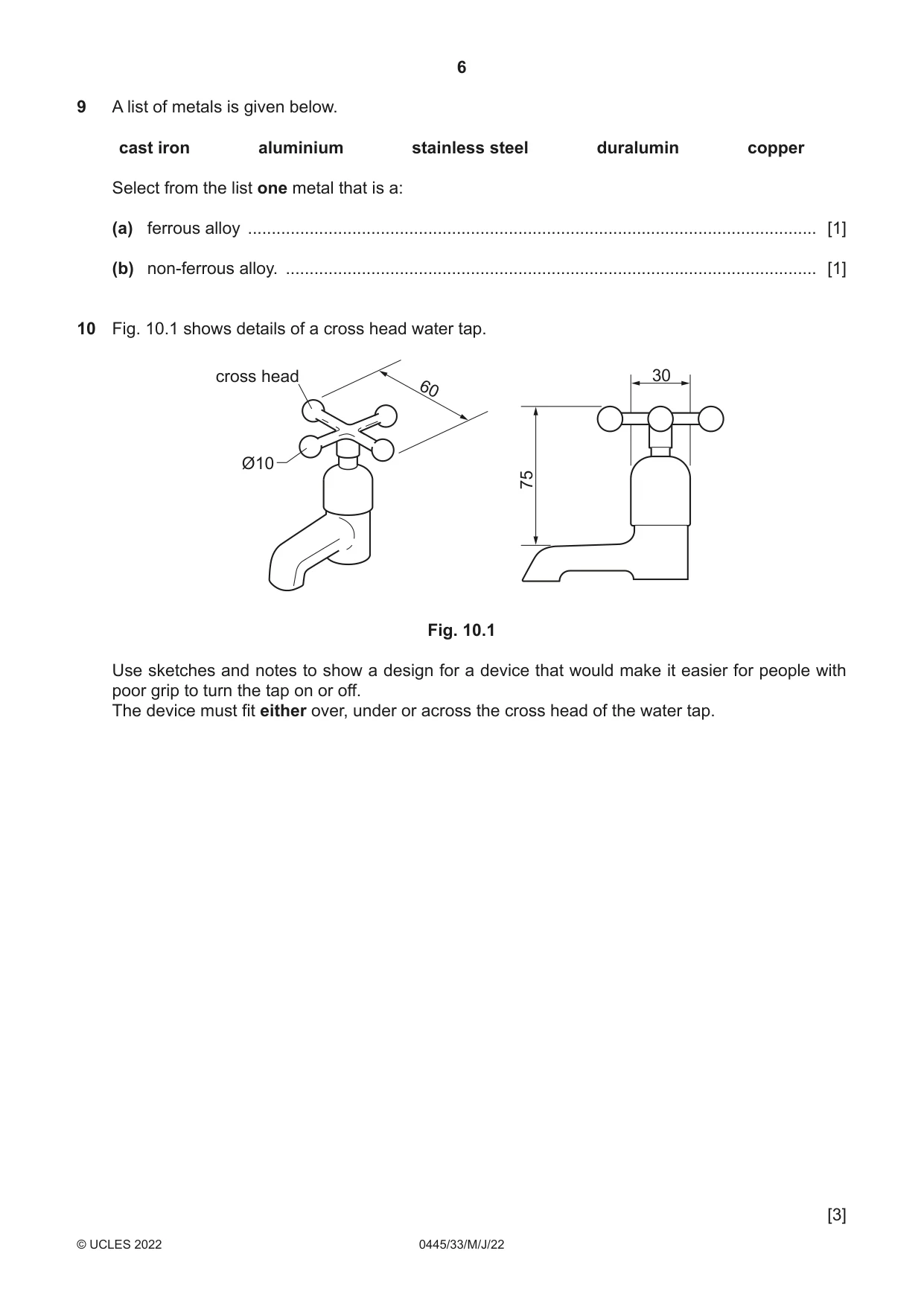
8 Fig. 8.1 shows a cycle helmet. inner cushioned lining outer shell Fig. 8.1 A list of plastics is given below. nylon polycarbonate polypropylene expanded polystyrene acrylic (a) Select from the list one plastic that is suitable for the outer shell. ............................................................................................................................................. [1] (b) Select from the list one plastic that is suitable for the inner lining. ............................................................................................................................................. [1]
Mark scheme: 8(a) Polycarbonate 1 8(b) Expanded polystyrene 1
Q9 · A list of metals is given below
9 A list of metals is given below. cast iron aluminium stainless steel duralumin copper Select from the list one metal that is a: (a) ferrous alloy ........................................................................................................................ [1] (b) non-ferrous alloy. ................................................................................................................ [1]
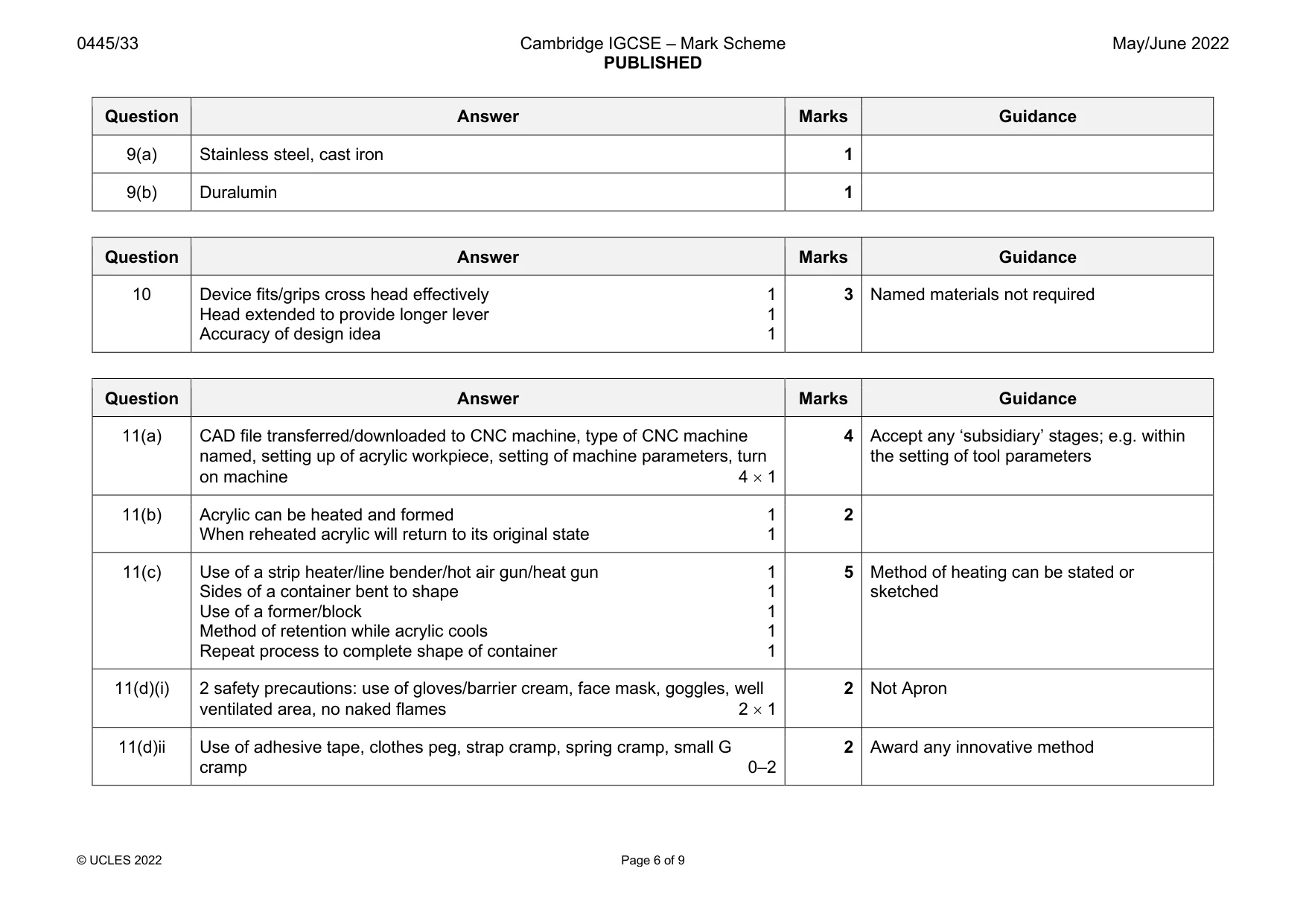
Mark scheme: 9(a) Stainless steel, cast iron 1 9(b) Duralumin 1
Q10 · Details of a cross head water tap
10 Fig. 10.1 shows details of a cross head water tap. cross head 30 60 Ø10 75 Fig. 10.1 Use sketches and notes to show a design for a device that would make it easier for people with poor grip to turn the tap on or off. The device must fit either over, under or across the cross head of the water tap. [3]
Mark scheme: 10 Device fits/grips cross head effectively 1 3 Named materials not required Head extended to provide longer lever 1 Accuracy of design idea 1
Q11 · An incomplete design for a table top organiser made from acrylic
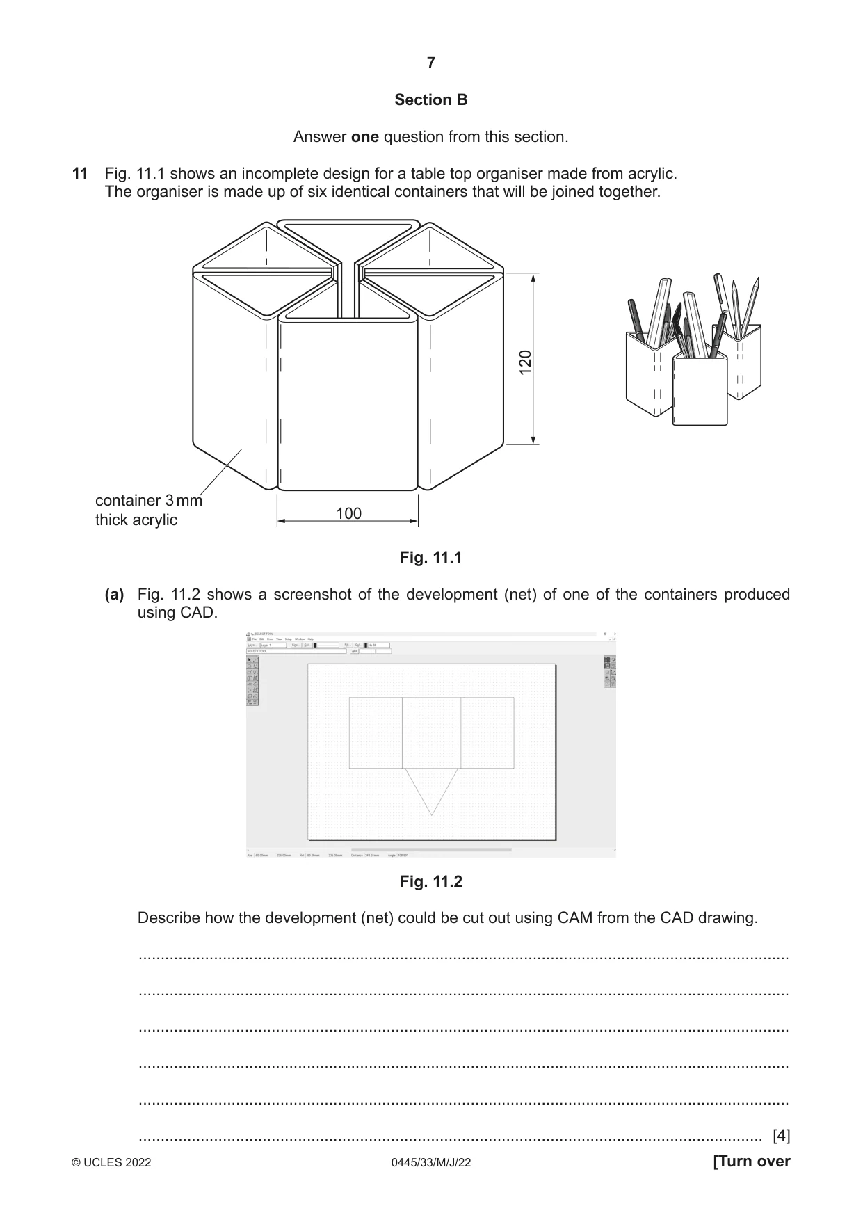
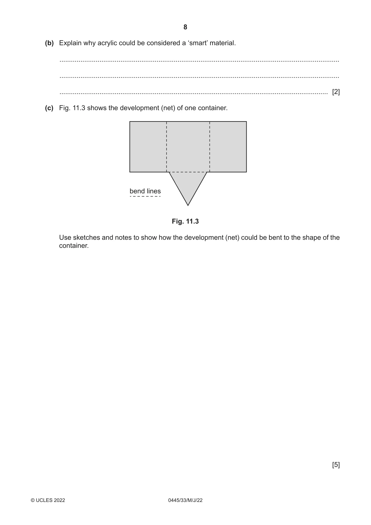
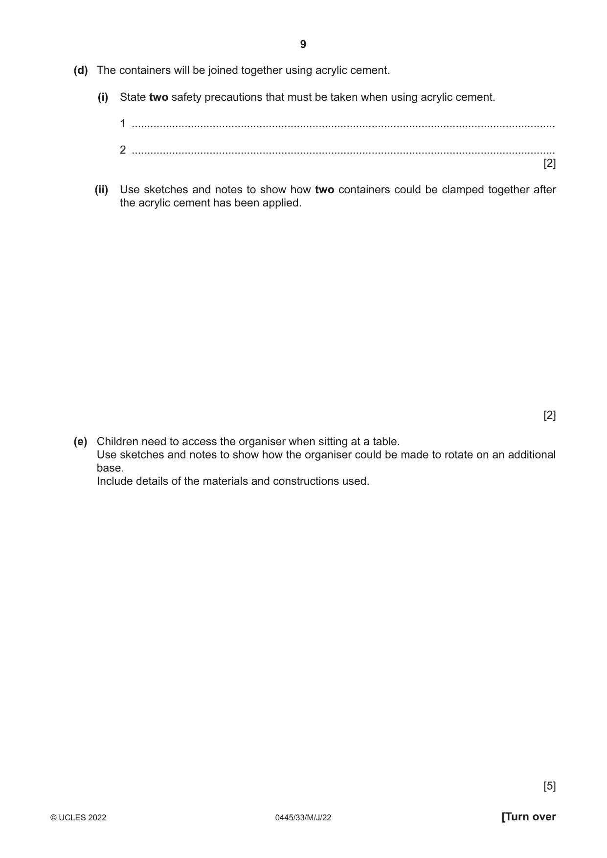
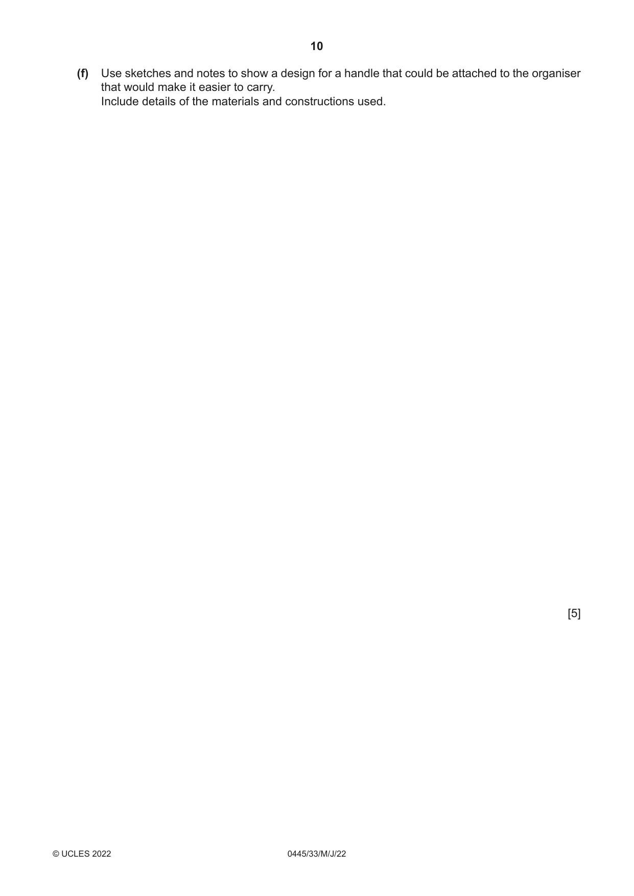
11 Fig. 11.1 shows an incomplete design for a table top organiser made from acrylic. The organiser is made up of six identical containers that will be joined together. 120 container 3 mm 100 thick acrylic Fig. 11.1 (a) Fig. 11.2 shows a screenshot of the development (net) of one of the containers produced using CAD. Fig. 11.2 Describe how the development (net) could be cut out using CAM from the CAD drawing. ................................................................................................................................................... ................................................................................................................................................... ................................................................................................................................................... ................................................................................................................................................... ................................................................................................................................................... ............................................................................................................................................. [4] (b) Explain why acrylic could be considered a ‘smart’ material. ................................................................................................................................................... ................................................................................................................................................... ............................................................................................................................................. [2] (c) Fig. 11.3 shows the development (net) of one container. bend lines Fig. 11.3 Use sketches and notes to show how the development (net) could be bent to the shape of the container. [5] (d) The containers will be joined together using acrylic cement. (i) State two safety precautions that must be taken when using acrylic cement. 1 ........................................................................................................................................ 2 ........................................................................................................................................ [2] (ii) Use sketches and notes to show how two containers could be clamped together after the acrylic cement has been applied. [2] (e) Children need to access the organiser when sitting at a table. Use sketches and notes to show how the organiser could be made to rotate on an additional base. Include details of the materials and constructions used. [5] (f) Use sketches and notes to show a design for a handle that could be attached to the organiser that would make it easier to carry. Include details of the materials and constructions used. [5]
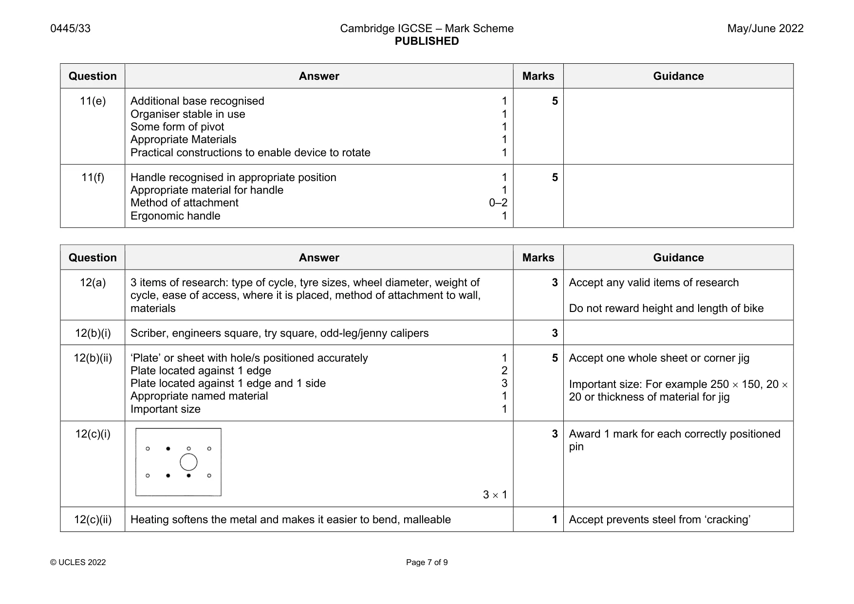
Mark scheme: 11(a) CAD file transferred/downloaded to CNC machine, type of CNC machine 4 Accept any ‘subsidiary’ stages; e.g. within named, setting up of acrylic workpiece, setting of machine parameters, turn the setting of tool parameters on machine 4 × 1 11(b) Acrylic can be heated and formed 1 2 When reheated acrylic will return to its original state 1 11(c) Use of a strip heater/line bender/hot air gun/heat gun 1 5 Method of heating can be stated or Sides of a container bent to shape 1 sketched Use of a former/block 1 Method of retention while acrylic cools 1 Repeat process to complete shape of container 1 11(d)(i) 2 safety precautions: use of gloves/barrier cream, face mask, goggles, well 2 Not Apron ventilated area, no naked flames 2 × 1 11(d)ii Use of adhesive tape, clothes peg, strap cramp, spring cramp, small G 2 Award any innovative method cramp 0–2 11(e) Additional base recognised 1 5 Organiser stable in use 1 Some form of pivot 1 Appropriate Materials 1 Practical constructions to enable device to rotate 1 11(f) Handle recognised in appropriate position 1 5 Appropriate material for handle 1 Method of attachment 0–2 Ergonomic handle 1
Q12 · A wall-mounted cycle rack made from mild steel
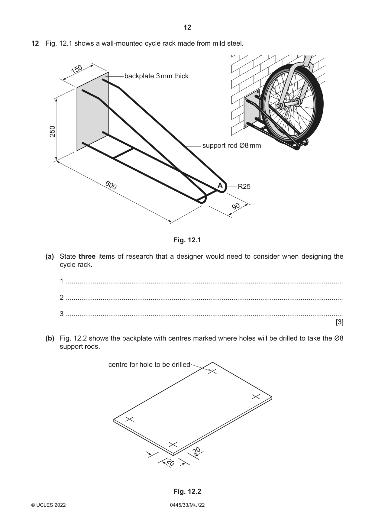
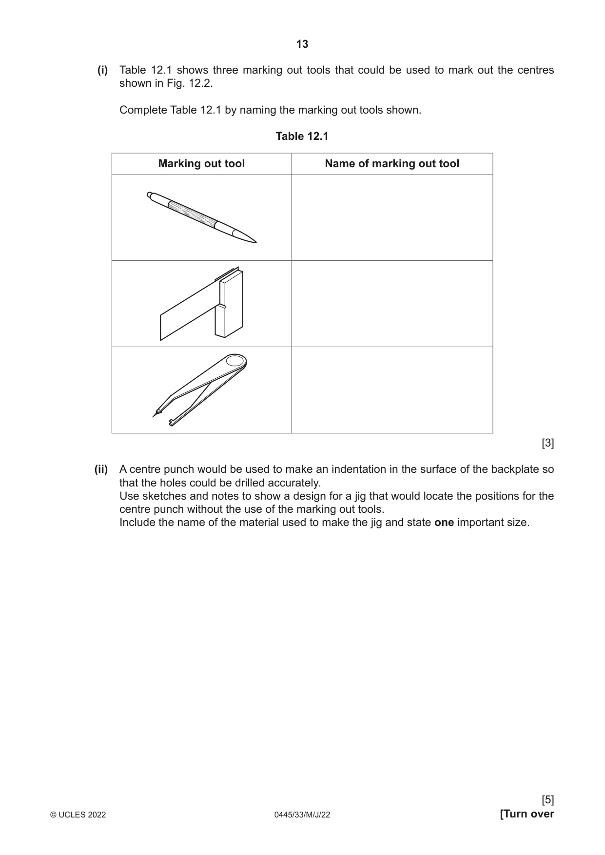
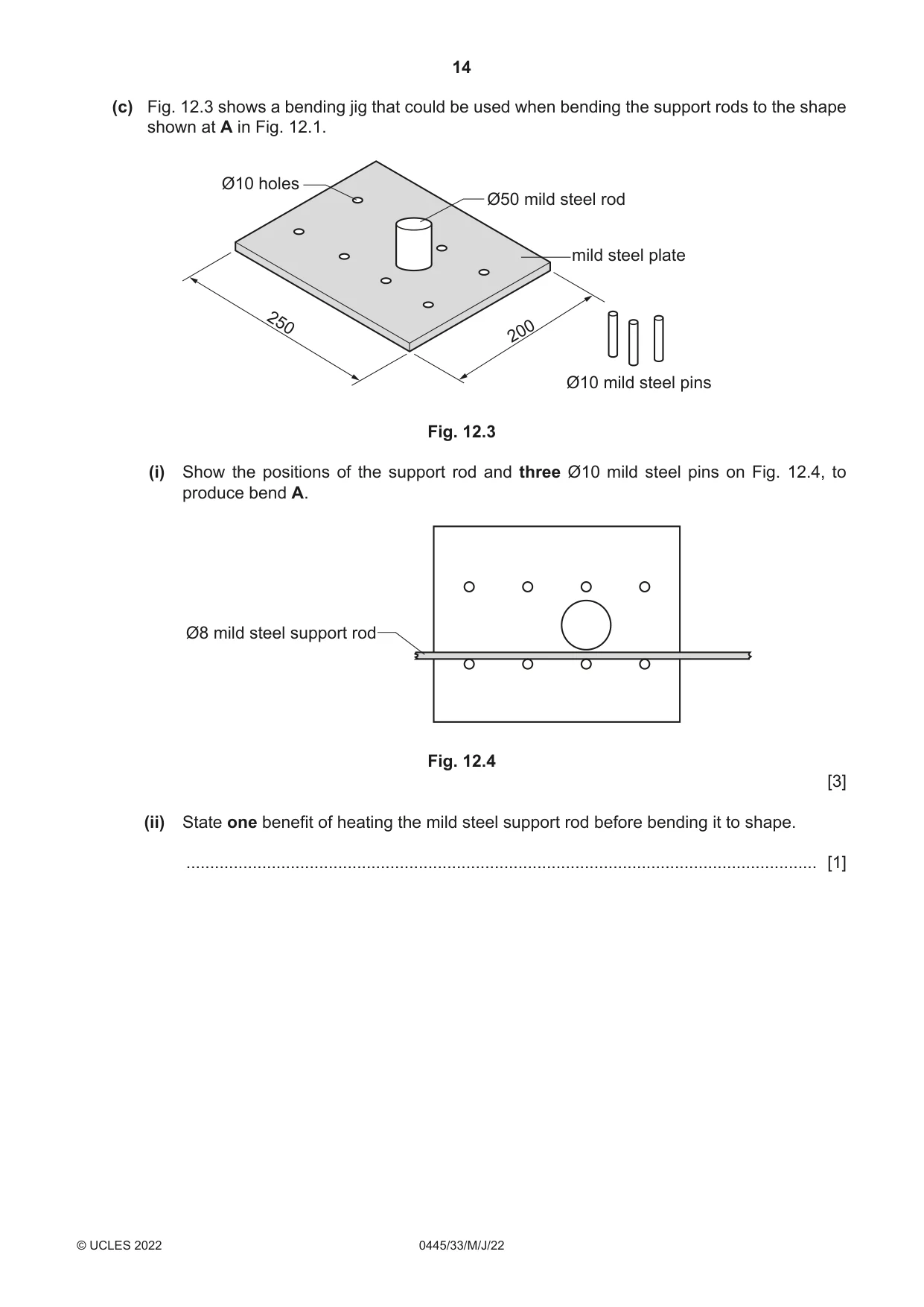
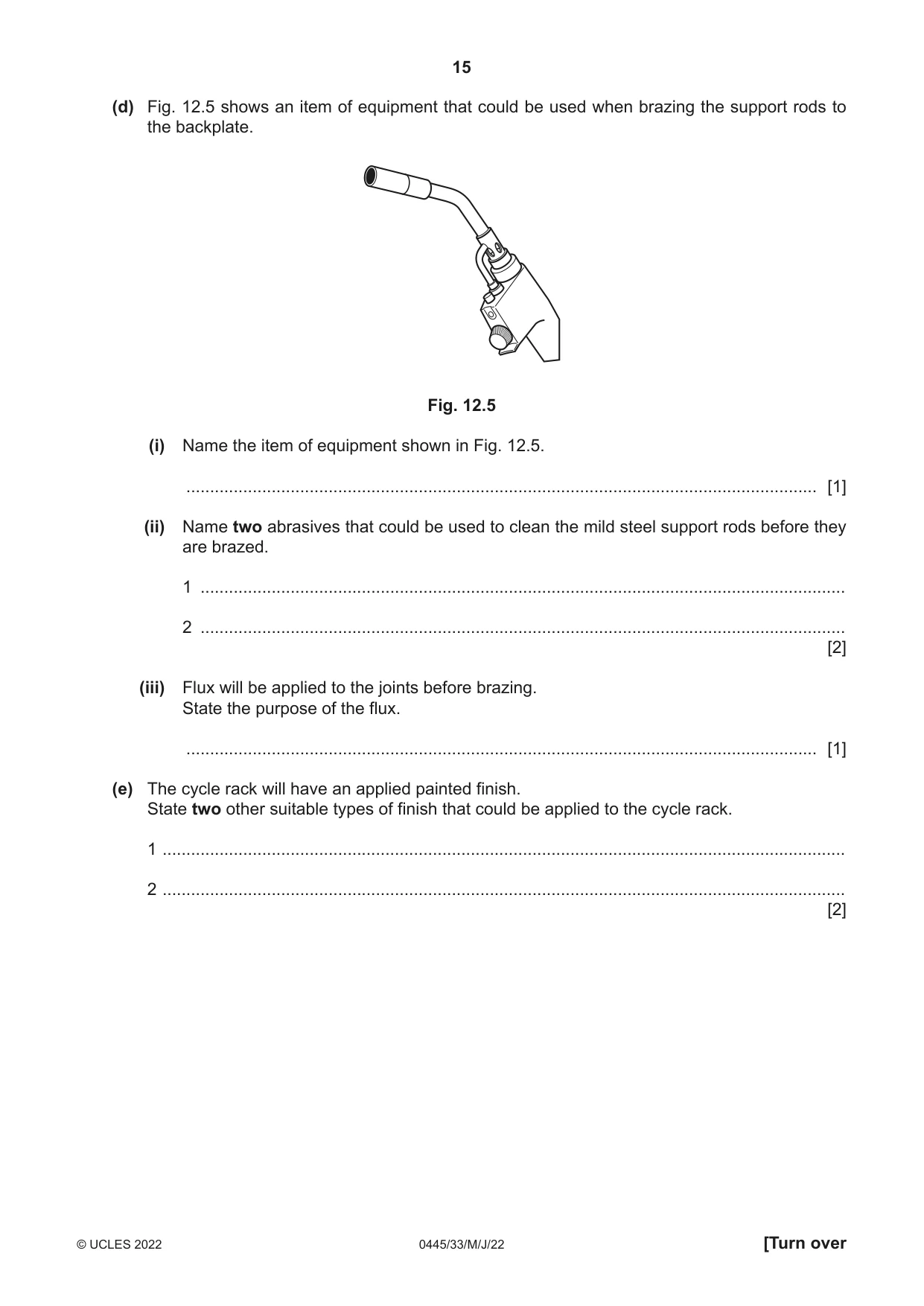
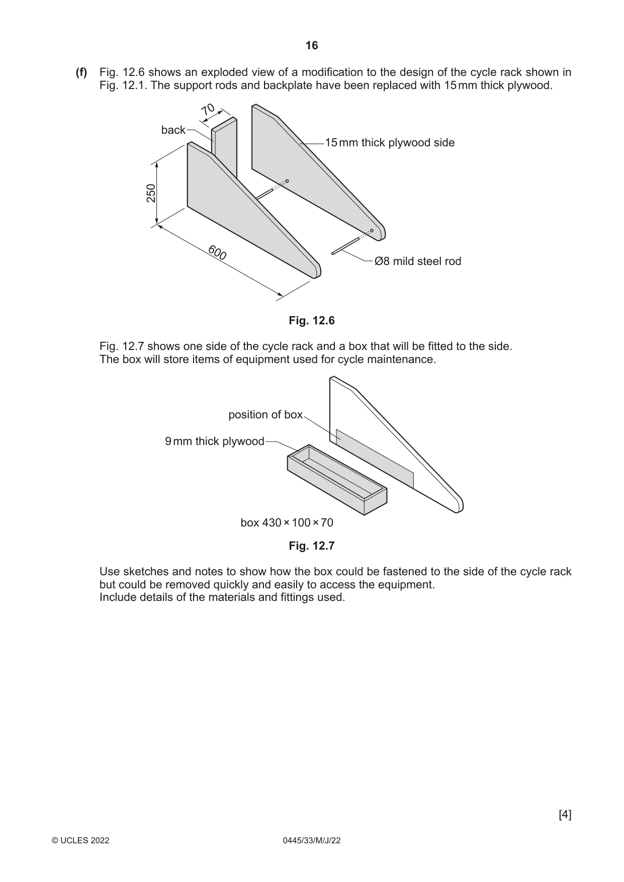
12 Fig. 12.1 shows a wall-mounted cycle rack made from mild steel. 150 backplate 3 mm thick 250 support rod Ø8 mm 600 A R25 90 Fig. 12.1 (a) State three items of research that a designer would need to consider when designing the cycle rack. 1 ................................................................................................................................................ 2 ................................................................................................................................................ 3 ................................................................................................................................................ [3] (b) Fig. 12.2 shows the backplate with centres marked where holes will be drilled to take the Ø8 support rods. centre for hole to be drilled 20 20 Fig. 12.2 (i) Table 12.1 shows three marking out tools that could be used to mark out the centres shown in Fig. 12.2. Complete Table 12.1 by naming the marking out tools shown. Table 12.1 Marking out tool Name of marking out tool [3] (ii) A centre punch would be used to make an indentation in the surface of the backplate so that the holes could be drilled accurately. Use sketches and notes to show a design for a jig that would locate the positions for the centre punch without the use of the marking out tools. Include the name of the material used to make the jig and state one important size. [5] (c) Fig. 12.3 shows a bending jig that could be used when bending the support rods to the shape shown at A in Fig. 12.1. Ø10 holes Ø50 mild steel rod mild steel plate 250 200 Ø10 mild steel pins Fig. 12.3 (i) Show the positions of the support rod and three Ø10 mild steel pins on Fig. 12.4, to produce bend A. Ø8 mild steel support rod Fig. 12.4 [3] (ii) State one benefit of heating the mild steel support rod before bending it to shape. ..................................................................................................................................... [1] (d) Fig. 12.5 shows an item of equipment that could be used when brazing the support rods to the backplate. Fig. 12.5 (i) Name the item of equipment shown in Fig. 12.5. ..................................................................................................................................... [1] (ii) Name two abrasives that could be used to clean the mild steel support rods before they are brazed. 1 ........................................................................................................................................ 2 ........................................................................................................................................ [2] (iii) Flux will be applied to the joints before brazing. State the purpose of the flux. ..................................................................................................................................... [1] (e) The cycle rack will have an applied painted finish. State two other suitable types of finish that could be applied to the cycle rack. 1 ................................................................................................................................................ 2 ................................................................................................................................................ [2] (f) Fig. 12.6 shows an exploded view of a modification to the design of the cycle rack shown in Fig. 12.1. The support rods and backplate have been replaced with 15 mm thick plywood. 70 back 15 mm thick plywood side 250 600 Ø8 mild steel rod Fig. 12.6 Fig. 12.7 shows one side of the cycle rack and a box that will be fitted to the side. The box will store items of equipment used for cycle maintenance. position of box 9 mm thick plywood box 430 × 100 × 70 Fig. 12.7 Use sketches and notes to show how the box could be fastened to the side of the cycle rack but could be removed quickly and easily to access the equipment. Include details of the materials and fittings used. [4]
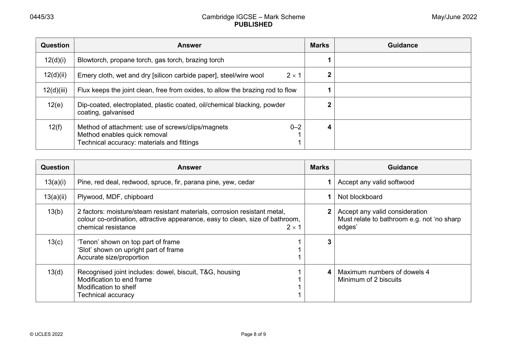
Mark scheme: 12(a) 3 items of research: type of cycle, tyre sizes, wheel diameter, weight of 3 Accept any valid items of research cycle, ease of access, where it is placed, method of attachment to wall, materials Do not reward height and length of bike 12(b)(i) Scriber, engineers square, try square, odd-leg/jenny calipers 3 12(b)(ii) ‘Plate’ or sheet with hole/s positioned accurately 1 5 Accept one whole sheet or corner jig Plate located against 1 edge 2 Plate located against 1 edge and 1 side 3 Important size: For example 250 × 150, 20 × Appropriate named material 1 20 or thickness of material for jig Important size 1 12(c)(i) 3 Award 1 mark for each correctly positioned pin 3 × 1 12(c)(ii) Heating softens the metal and makes it easier to bend, malleable 1 Accept prevents steel from ‘cracking’ 12(d)(i) Blowtorch, propane torch, gas torch, brazing torch 1 12(d)(ii) Emery cloth, wet and dry [silicon carbide paper], steel/wire wool 2 × 1 2 12(d)(iii) Flux keeps the joint clean, free from oxides, to allow the brazing rod to flow 1 12(e) Dip-coated, electroplated, plastic coated, oil/chemical blacking, powder 2 coating, galvanised 12(f) Method of attachment: use of screws/clips/magnets 0–2 4 Method enables quick removal 1 Technical accuracy: materials and fittings 1
Q13 · An incomplete design for a wall-mounted shelf unit for a bathroom
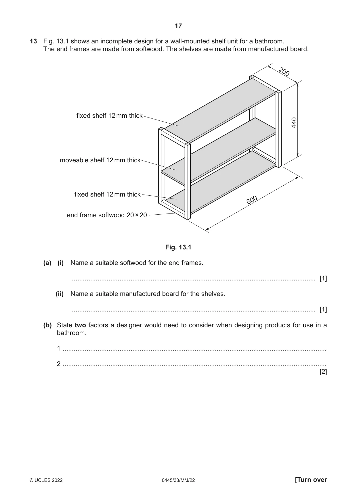
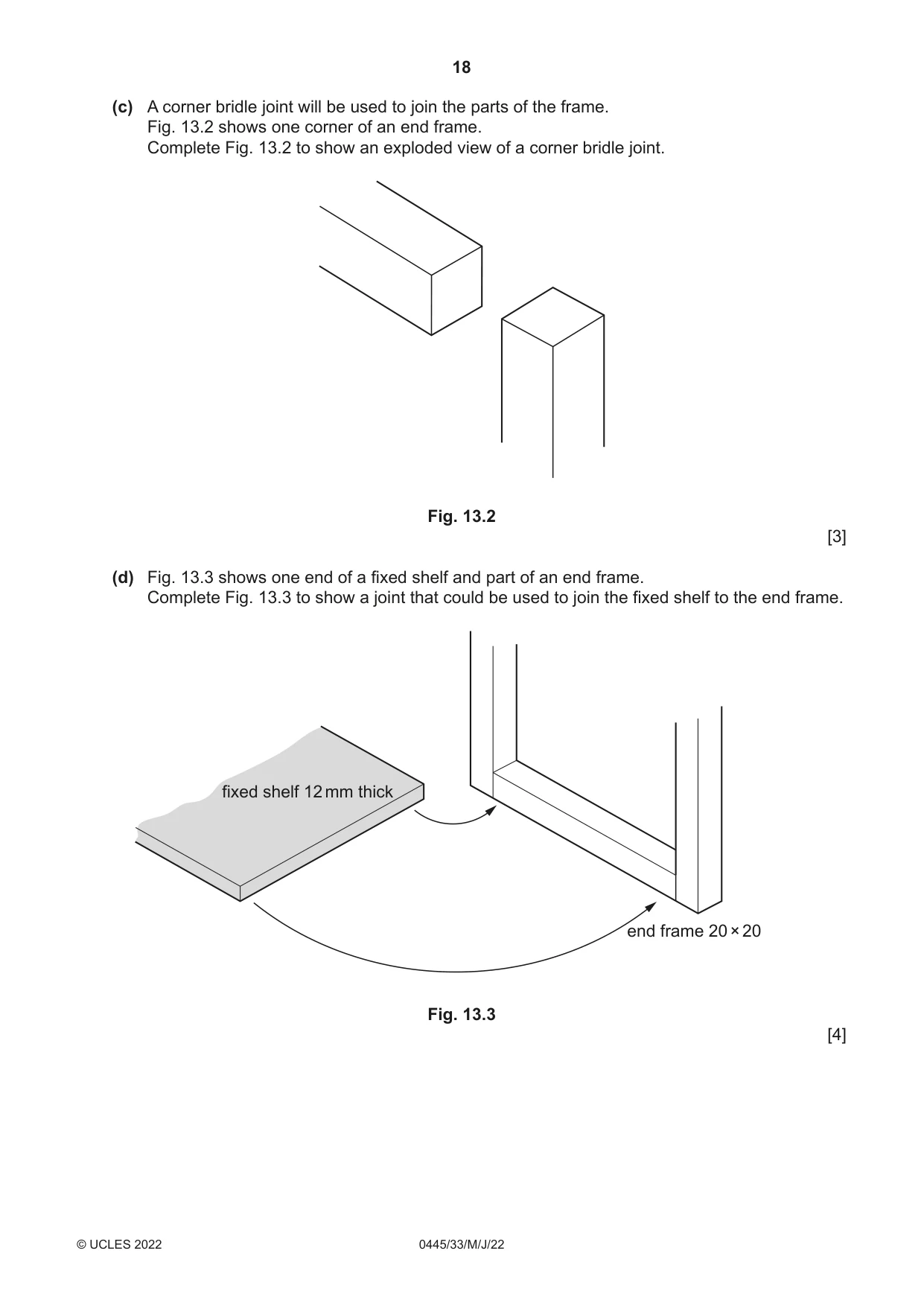
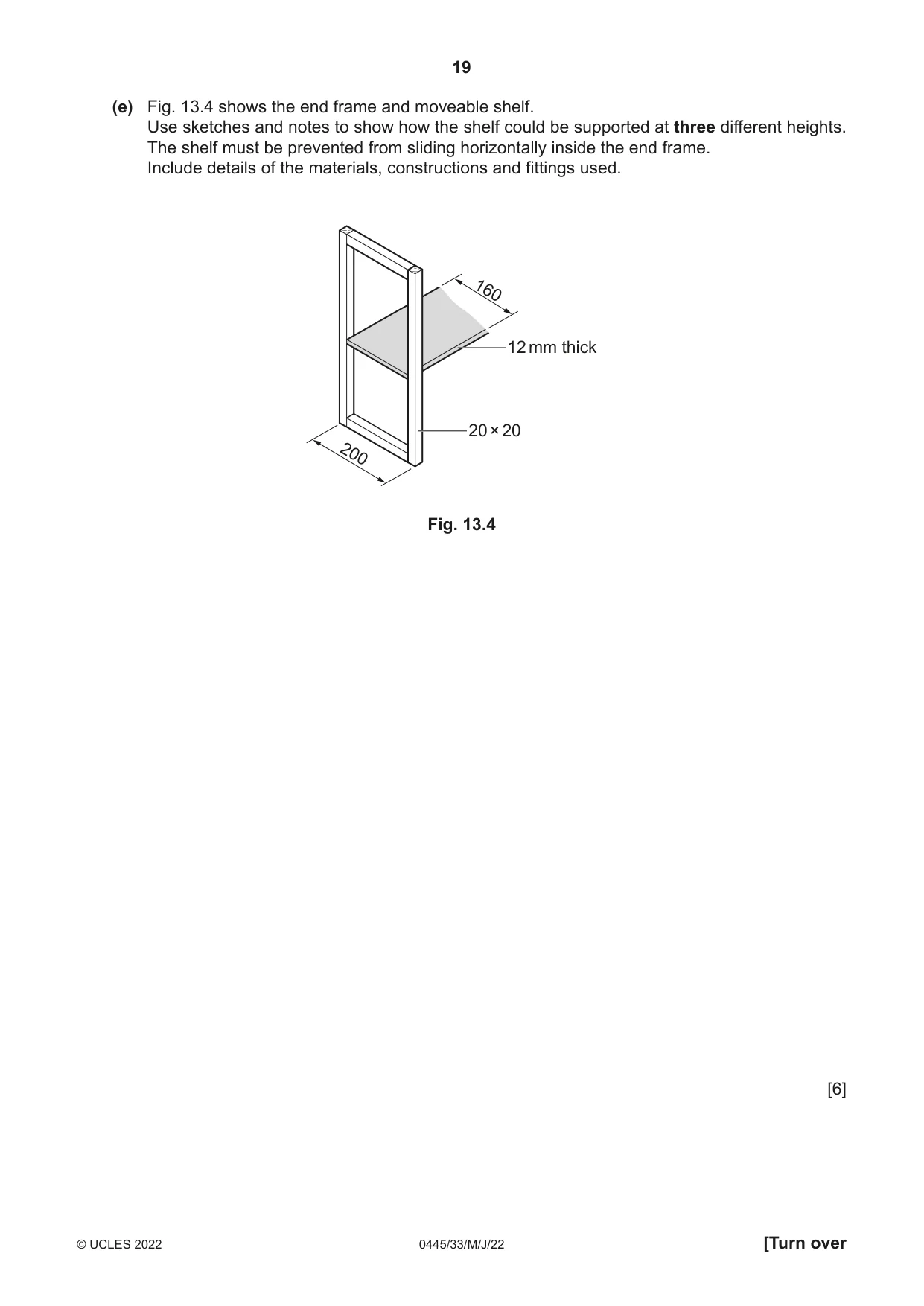
13 Fig. 13.1 shows an incomplete design for a wall-mounted shelf unit for a bathroom. The end frames are made from softwood. The shelves are made from manufactured board. 200 fixed shelf 12 mm thick 440 moveable shelf 12 mm thick fixed shelf 12 mm thick 600 end frame softwood 20 × 20 Fig. 13.1 (a) (i) Name a suitable softwood for the end frames. ..................................................................................................................................... [1] (ii) Name a suitable manufactured board for the shelves. ..................................................................................................................................... [1] (b) State two factors a designer would need to consider when designing products for use in a bathroom. 1 ................................................................................................................................................ 2 ................................................................................................................................................ [2] (c) A corner bridle joint will be used to join the parts of the frame. Fig. 13.2 shows one corner of an end frame. Complete Fig. 13.2 to show an exploded view of a corner bridle joint. Fig. 13.2 [3] (d) Fig. 13.3 shows one end of a fixed shelf and part of an end frame. Complete Fig. 13.3 to show a joint that could be used to join the fixed shelf to the end frame. fixed shelf 12 mm thick end frame 20 × 20 Fig. 13.3 [4] (e) Fig. 13.4 shows the end frame and moveable shelf. Use sketches and notes to show how the shelf could be supported at three different heights. The shelf must be prevented from sliding horizontally inside the end frame. Include details of the materials, constructions and fittings used. 160 12 mm thick 20 × 20 200 Fig. 13.4 [6]
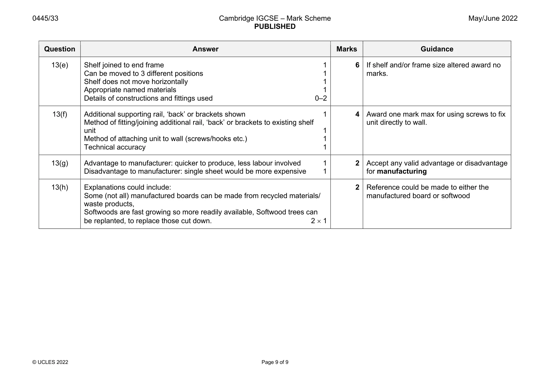
Mark scheme: 13(a)(i) Pine, red deal, redwood, spruce, fir, parana pine, yew, cedar 1 Accept any valid softwood 13(a)(ii) Plywood, MDF, chipboard 1 Not blockboard 13(b) 2 factors: moisture/steam resistant materials, corrosion resistant metal, 2 Accept any valid consideration colour co-ordination, attractive appearance, easy to clean, size of bathroom, Must relate to bathroom e.g. not ‘no sharp chemical resistance 2 × 1 edges’ 13(c) ‘Tenon’ shown on top part of frame 1 3 ‘Slot’ shown on upright part of frame 1 Accurate size/proportion 1 13(d) Recognised joint includes: dowel, biscuit, T&G, housing 1 4 Maximum numbers of dowels 4 Modification to end frame 1 Minimum of 2 biscuits Modification to shelf 1 Technical accuracy 1 13(e) Shelf joined to end frame 1 6 If shelf and/or frame size altered award no Can be moved to 3 different positions 1 marks. Shelf does not move horizontally 1 Appropriate named materials 1 Details of constructions and fittings used 0–2 13(f) Additional supporting rail, ‘back’ or brackets shown 1 4 Award one mark max for using screws to fix Method of fitting/joining additional rail, ‘back’ or brackets to existing shelf unit directly to wall. unit 1 Method of attaching unit to wall (screws/hooks etc.) 1 Technical accuracy 1 13(g) Advantage to manufacturer: quicker to produce, less labour involved 1 2 Accept any valid advantage or disadvantage Disadvantage to manufacturer: single sheet would be more expensive 1 for manufacturing 13(h) Explanations could include: 2 Reference could be made to either the Some (not all) manufactured boards can be made from recycled materials/ manufactured board or softwood waste products, Softwoods are fast growing so more readily available, Softwood trees can be replanted, to replace those cut down. 2 × 1
What was in this paper
The subtopics covered by these 13 questions, and how many questions each got. Open one in a new tab to see every Cambridge question on it.
What you needed in this session
Cambridge’s own grade thresholds for 2022 May/June, Paper 3 · Variant 3. A higher threshold means an easier paper — the bar moves with how the cohort did.