Questions as text
Q1 · A coaxial cable is frequently used to connect an aerial to a television receiver 9702/43 Oct/Nov 2017
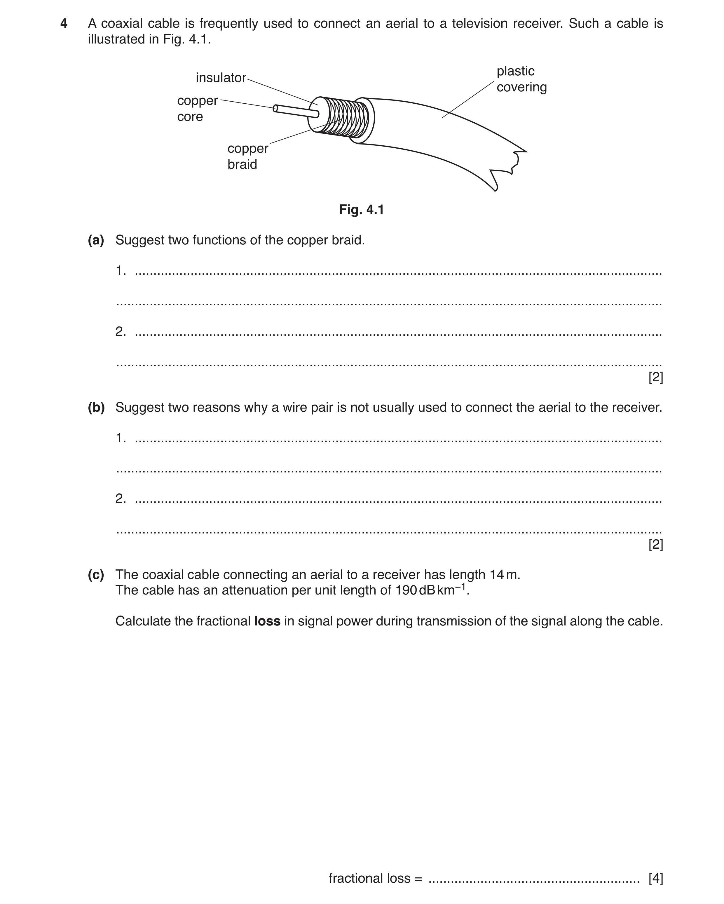
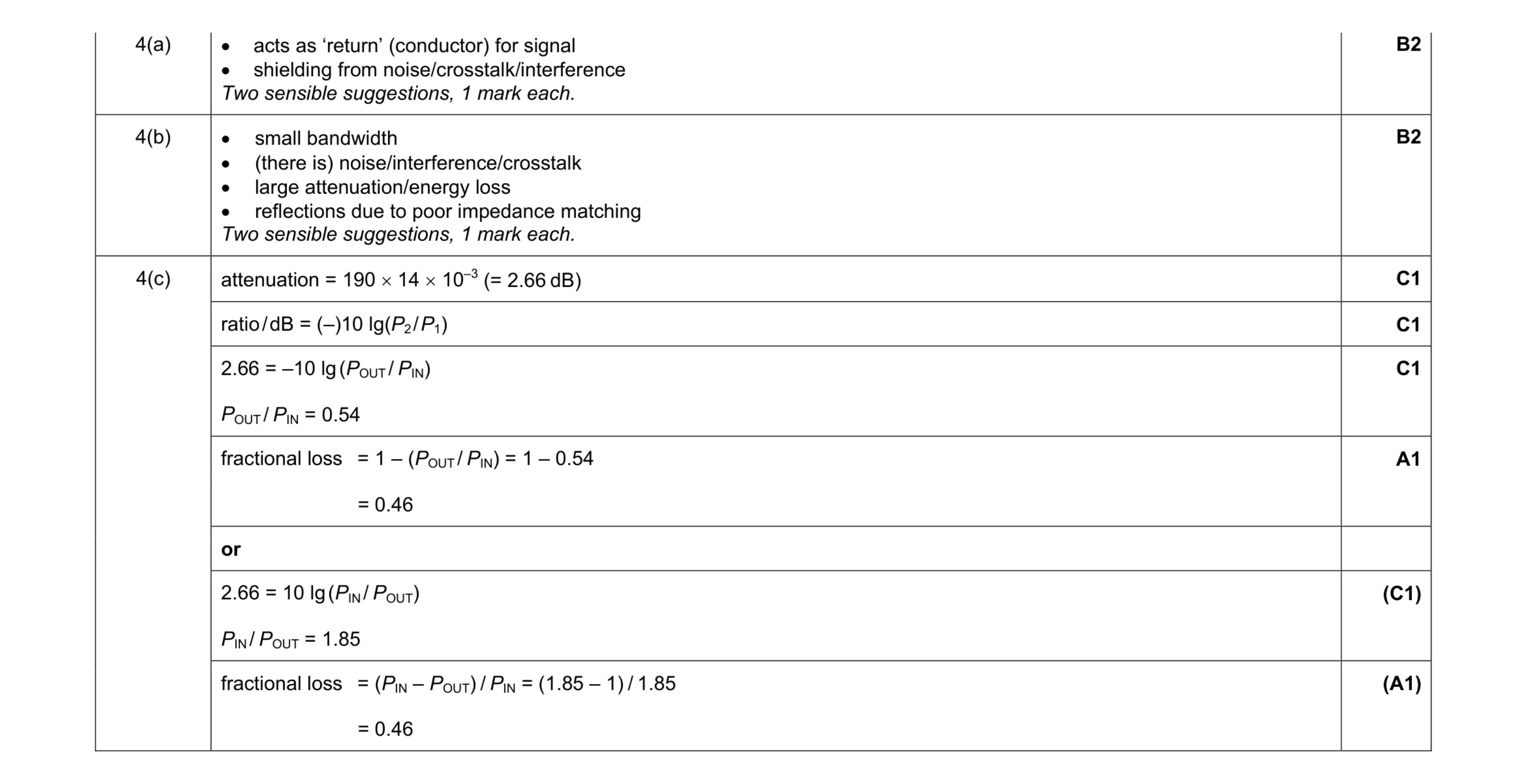
4 A coaxial cable is frequently used to connect an aerial to a television receiver. Such a cable is illustrated in Fig. 4.1. plastic insulator covering copper core copper braid Fig. 4.1 (a) Suggest two functions of the copper braid. 1. … … 2. … … [2] (b) Suggest two reasons why a wire pair is not usually used to connect the aerial to the receiver. 1. … … 2. … … [2] (c) The coaxial cable connecting an aerial to a receiver has length 14 m. The cable has an attenuation per unit length of 190 dB km−1. Calculate the fractional loss in signal power during transmission of the signal along the cable. fractional loss = … [4]
8 marks
Mark scheme: 4(a) acts as ‘return’ (conductor) for signal • shielding from noise/crosstalk/interference Two sensible suggestions, 1 mark each. B2 4(b) • small bandwidth • (there is) noise/interference/crosstalk • large attenuation/energy loss • reflections due to poor impedance matching Two sensible suggestions, 1 mark each. B2 4(c) attenuation = 190 × 14 × 10–3 (= 2.66 dB) C1 ratio / dB = (–)10 lg(P2 / P1) C1 2.66 = –10 lg (POUT / PIN) POUT/ PIN = 0.54 C1 fractional loss = 1 – (POUT / PIN) = 1 – 0.54 = 0.46 A1 or 2.66 = 10 lg (PIN / POUT) PIN/ POUT = 1.85 (C1) fractional loss = (PIN – POUT) / PIN = (1.85 – 1) / 1.85 = 0.46 (A1)
This question in 9702/43 Oct/Nov 2017
Q2 · A cross-section through a current-carrying solenoid is shown in Fig 9702/42 Feb/March 2019
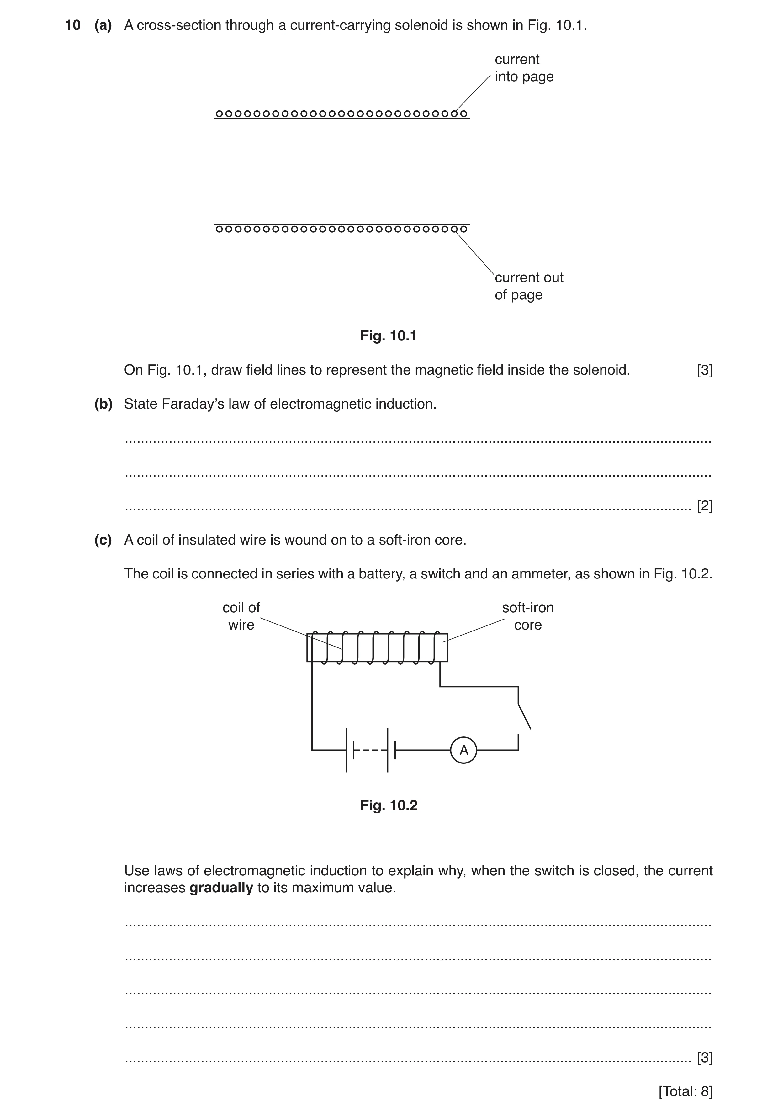
10 (a) A cross-section through a current-carrying solenoid is shown in Fig. 10.1. current into page current out of page Fig. 10.1 On Fig. 10.1, draw field lines to represent the magnetic field inside the solenoid. [3] (b) State Faraday’s law of electromagnetic induction. … … … [2] (c) A coil of insulated wire is wound on to a soft-iron core. The coil is connected in series with a battery, a switch and an ammeter, as shown in Fig. 10.2. coil of soft-iron wire core A Fig. 10.2 Use laws of electromagnetic induction to explain why, when the switch is closed, the current increases gradually to its maximum value. … … … … … [3] [Total: 8]
8 marks
Mark scheme: 10(a) single straight line along full length of solenoid B1 at least two more parallel lines along full length of solenoid B1 correct direction – right to left B1 10(b) (induced) e.m.f. proportional / equal to rate M1 of change of (magnetic) flux (linkage) A1 10(c) increasing current causes increasing flux B1 increasing flux induces e.m.f. in coil B1 (induced) e.m.f. opposes growth of current B1
This question in 9702/42 Feb/March 2019
Q3 · A long straight vertical wire carries a current I 9702/41 Oct/Nov 2019
8 (a) A long straight vertical wire carries a current I. The wire passes through a horizontal card EFGH, as shown in Fig. 8.1 and Fig. 8.2. current out of plane of paper H G I wire H G E F E F Fig. 8.1 Fig. 8.2 (view from above) On Fig. 8.2, draw the pattern of the magnetic field produced by the current-carrying wire on the plane EFGH. [3] (b) Two long straight parallel wires P and Q are situated a distance 3.1 cm apart, as illustrated in Fig. 8.3. 6.2 A 8.5 A wire P wire Q 3.1cm Fig. 8.3 The current in wire P is 6.2 A. The current in wire Q is 8.5 A. The magnetic flux density B at a distance x from a long straight wire carrying current I is given by the expression μ0I B = 2πx where μ0 is the permeability of free space. Calculate: (i) the magnetic flux density at wire Q due to the current in wire P flux density = … T [2] (ii) the force per unit length, in N m–1, acting on wire Q due to the current in wire P. force per unit length = … N m–1 [2] (c) The currents in wires P and Q are different in magnitude. State and explain whether the forces per unit length on the two wires will be different. … … … [2] [Total: 9]
9 marks
Mark scheme: 8(a) concentric circles (around the wire) M1 at least 3 circles shown, all with increasing separation A1 direction anticlockwise B1 8(b)(i) B = (4π × 10–7 × 6.2) / (2π × 3.1 × 10–2) C1 B = 4.0 × 10⁻⁵ T A1 8(b)(ii) F = BIL or F / L = BI C1 F / L = 4.0 × 10–5 × 8.5F / L = 3.4 × 10⁻⁴ N m–1 A1 8(c) correct application of Newton’s 3rd law to the forces or F / L is proportional to the product of the two currents M1 so same magnitude A1
This question in 9702/41 Oct/Nov 2019
Q4 · A long straight vertical wire carries a current I 9702/43 Oct/Nov 2019
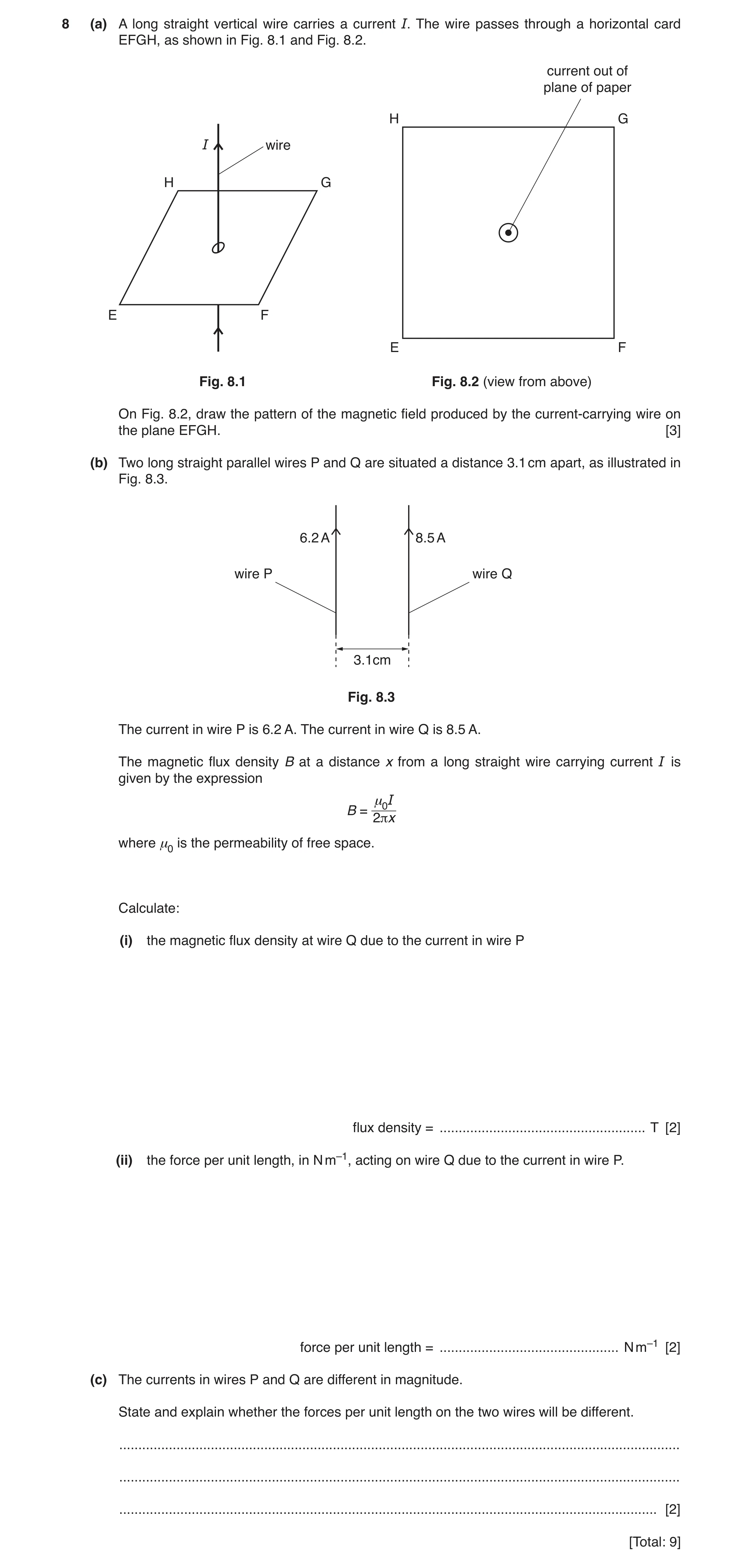
8 (a) A long straight vertical wire carries a current I. The wire passes through a horizontal card EFGH, as shown in Fig. 8.1 and Fig. 8.2. current out of plane of paper H G I wire H G E F E F Fig. 8.1 Fig. 8.2 (view from above) On Fig. 8.2, draw the pattern of the magnetic field produced by the current-carrying wire on the plane EFGH. [3] (b) Two long straight parallel wires P and Q are situated a distance 3.1 cm apart, as illustrated in Fig. 8.3. 6.2 A 8.5 A wire P wire Q 3.1cm Fig. 8.3 The current in wire P is 6.2 A. The current in wire Q is 8.5 A. The magnetic flux density B at a distance x from a long straight wire carrying current I is given by the expression μ0I B = 2πx where μ0 is the permeability of free space. Calculate: (i) the magnetic flux density at wire Q due to the current in wire P flux density = … T [2] (ii) the force per unit length, in N m–1, acting on wire Q due to the current in wire P. force per unit length = … N m–1 [2] (c) The currents in wires P and Q are different in magnitude. State and explain whether the forces per unit length on the two wires will be different. … … … [2] [Total: 9]
9 marks
Mark scheme: 8(a) concentric circles (around the wire) M1 at least 3 circles shown, all with increasing separation A1 direction anticlockwise B1 8(b)(i) B = (4π × 10–7 × 6.2) / (2π × 3.1 × 10–2) C1 B = 4.0 × 10⁻⁵ T A1 8(b)(ii) F = BIL or F / L = BI C1 F / L = 4.0 × 10–5 × 8.5F / L = 3.4 × 10⁻⁴ N m–1 A1 8(c) correct application of Newton’s 3rd law to the forces or F / L is proportional to the product of the two currents M1 so same magnitude A1
This question in 9702/43 Oct/Nov 2019
Q5 · A long straight vertical wire A carries a current in an upward direction 9702/42 Oct/Nov 2020
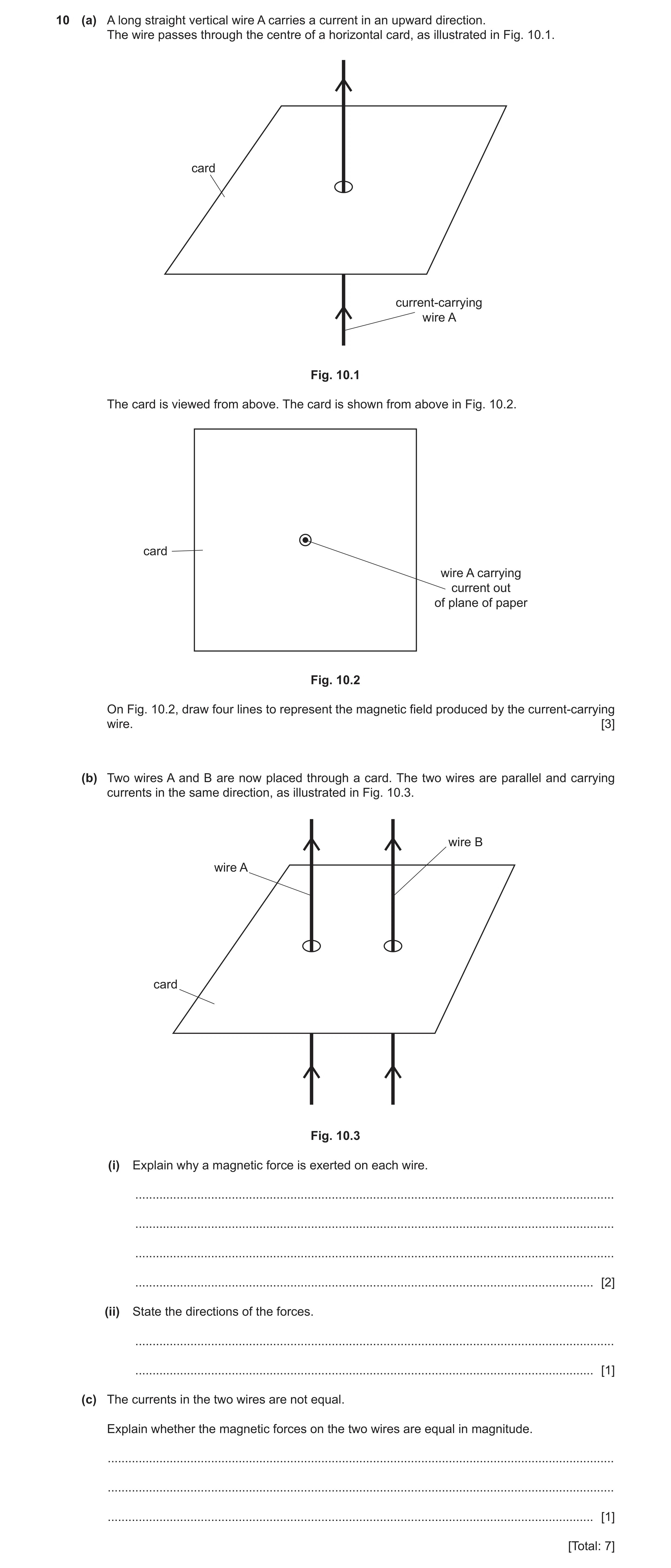
10 (a) A long straight vertical wire A carries a current in an upward direction. The wire passes through the centre of a horizontal card, as illustrated in Fig. 10.1. card current-carrying wire A Fig. 10.1 The card is viewed from above. The card is shown from above in Fig. 10.2. card wire A carrying current out of plane of paper Fig. 10.2 On Fig. 10.2, draw four lines to represent the magnetic field produced by the current-carrying wire. [3] (b) Two wires A and B are now placed through a card. The two wires are parallel and carrying currents in the same direction, as illustrated in Fig. 10.3. wire B wire A card Fig. 10.3 (i) Explain why a magnetic force is exerted on each wire. … … … … [2] (ii) State the directions of the forces. … … [1] (c) The currents in the two wires are not equal. Explain whether the magnetic forces on the two wires are equal in magnitude. … … … [1] [Total: 7]
7 marks
Mark scheme: 10(a) concentric circles centred on the wire B1 separation of lines increasing with distance from wire B1 arrows show anti-clockwise direction B1 10(b)(i) current in (each) wire creates a magnetic field (at the other wire) B1 current (in wire) at 90° to field causes force B1 10(b)(ii) force on each wire towards other wire/attractive B1 10(c) Newton’s third law pair of forces so yes (forces are equal) or force proportional to product of both currents so yes (forces are equal) B1
This question in 9702/42 Oct/Nov 2020
Q6 · Two long straight wires P and Q are parallel to each other, as shown in Fig 9702/42 Feb/March 2021
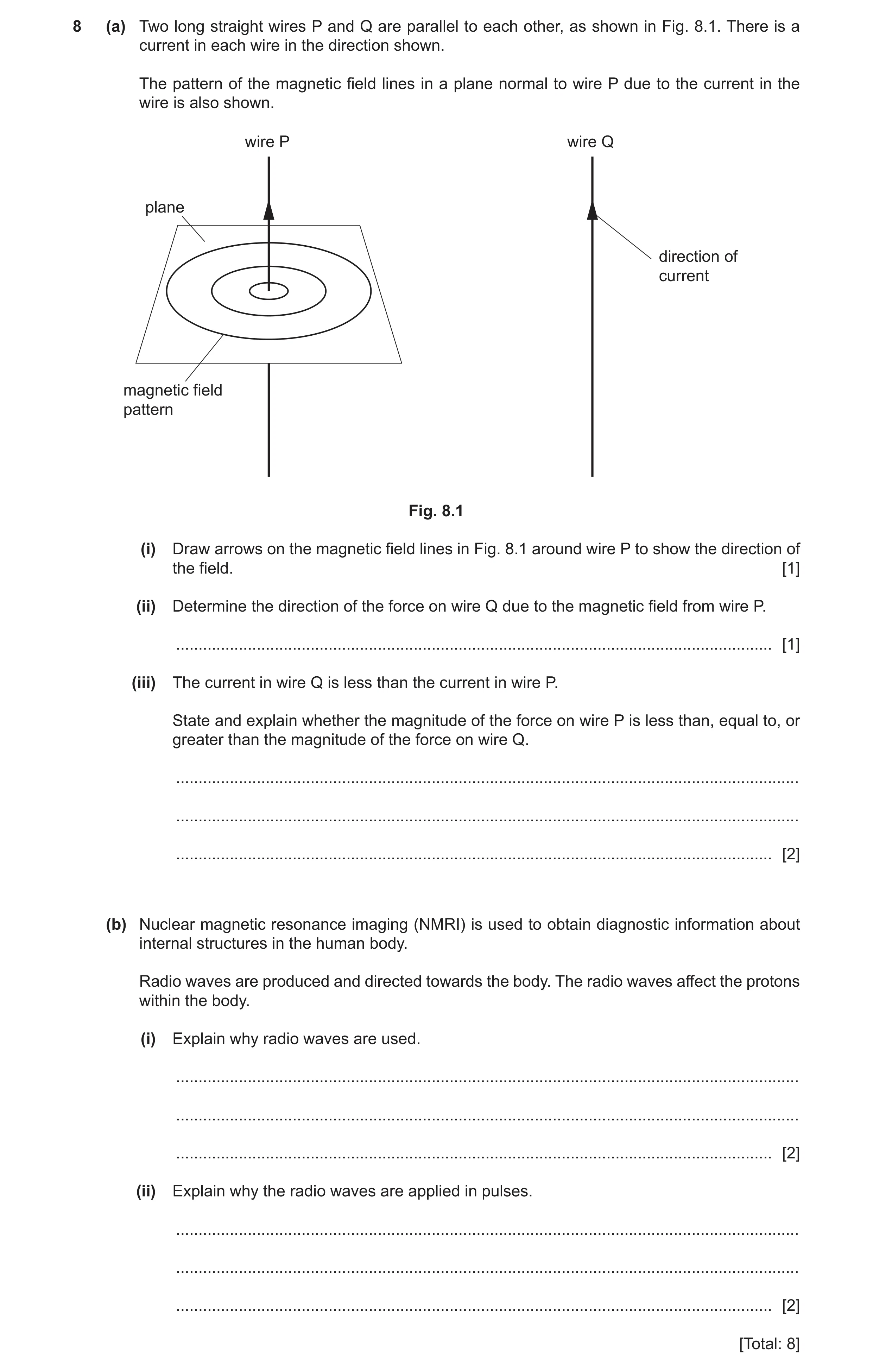
8 (a) Two long straight wires P and Q are parallel to each other, as shown in Fig. 8.1. There is a current in each wire in the direction shown. The pattern of the magnetic field lines in a plane normal to wire P due to the current in the wire is also shown. wire P wire Q plane direction of current magnetic field pattern Fig. 8.1 (i) Draw arrows on the magnetic field lines in Fig. 8.1 around wire P to show the direction of the field. [1] (ii) Determine the direction of the force on wire Q due to the magnetic field from wire P. … [1] (iii) The current in wire Q is less than the current in wire P. State and explain whether the magnitude of the force on wire P is less than, equal to, or greater than the magnitude of the force on wire Q. … … … [2] (b) Nuclear magnetic resonance imaging (NMRI) is used to obtain diagnostic information about internal structures in the human body. Radio waves are produced and directed towards the body. The radio waves affect the protons within the body. (i) Explain why radio waves are used. … … … [2] (ii) Explain why the radio waves are applied in pulses. … … … [2] [Total: 8]
8 marks
Mark scheme: 8(a)(i) at least one anticlockwise arrow and no clockwise arrows B1 8(a)(ii) (force is to the) left B1 8(a)(iii) force is the same B1 Newton’s third law (of motion) or force depends on the product of the two currents B1 Question Answer Marks 8(b)(i) frequency of radio waves is equal to natural frequency of protons B1 resonance of protons occurs / protons absorb energy B1 8(b)(ii) in between pulses / when pulse stops B1 Any 1 from: • protons de-excite • protons emit r.f. pulses • emitted (r.f.) pulse (from proton) detected B1
This question in 9702/42 Feb/March 2021
Q7 · State two situations in which a charged particle in a magnetic field does not experience… 9702/42 May/June 2021
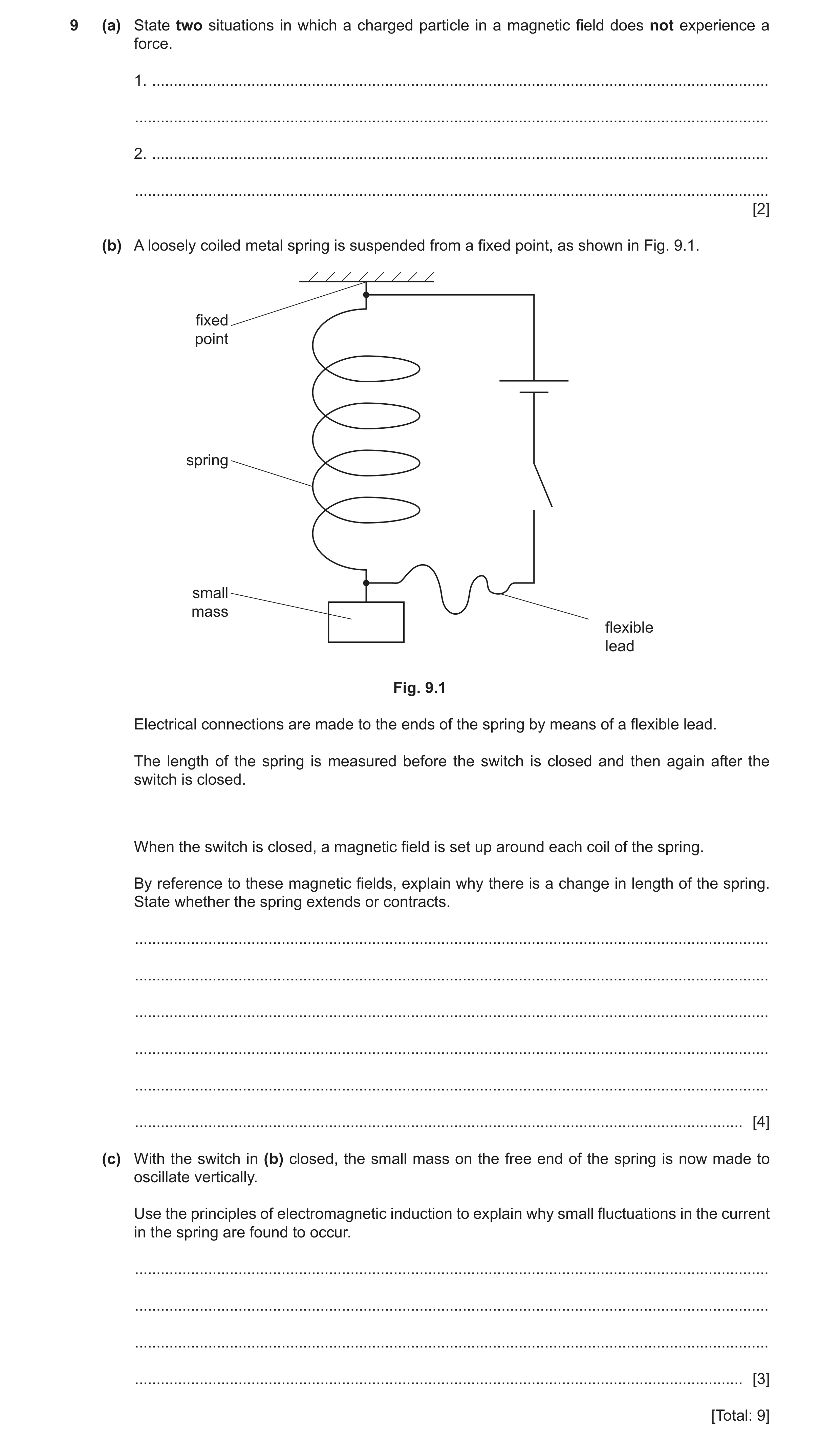
9 (a) State two situations in which a charged particle in a magnetic field does not experience a force. 1. … … 2. … … [2] (b) A loosely coiled metal spring is suspended from a fixed point, as shown in Fig. 9.1. fixed point spring small mass flexible lead Fig. 9.1 Electrical connections are made to the ends of the spring by means of a flexible lead. The length of the spring is measured before the switch is closed and then again after the switch is closed. When the switch is closed, a magnetic field is set up around each coil of the spring. By reference to these magnetic fields, explain why there is a change in length of the spring. State whether the spring extends or contracts. … … … … … … [4] (c) With the switch in (b) closed, the small mass on the free end of the spring is now made to oscillate vertically. Use the principles of electromagnetic induction to explain why small fluctuations in the current in the spring are found to occur. … … … … [3] [Total: 9]
9 marks
Mark scheme: 9(a) (particle is) stationary/not moving B1 (particle is) moving parallel to the (magnetic) field B1 9(b) magnetic field around each coil is circular or each coil is normal to magnetic field due to adjacent coils B1 current in coil interacts with (magnetic) field to exert force (on coil) B1 force is normal to both coil and magnetic field or force parallel to axis (of coil) B1 forces between coils are attractive so spring contracts B1 9(c) (oscillating) coils cut magnetic flux or as separation of coils changes, magnetic flux changes B1 cutting flux causes induced e.m.f. in coils B1 changing (induced) e.m.f. causes changing current (in coil) B1
This question in 9702/42 May/June 2021
Q8 · Two long straight parallel wires P and Q carry currents into the plane of the paper, as… 9702/42 Oct/Nov 2021
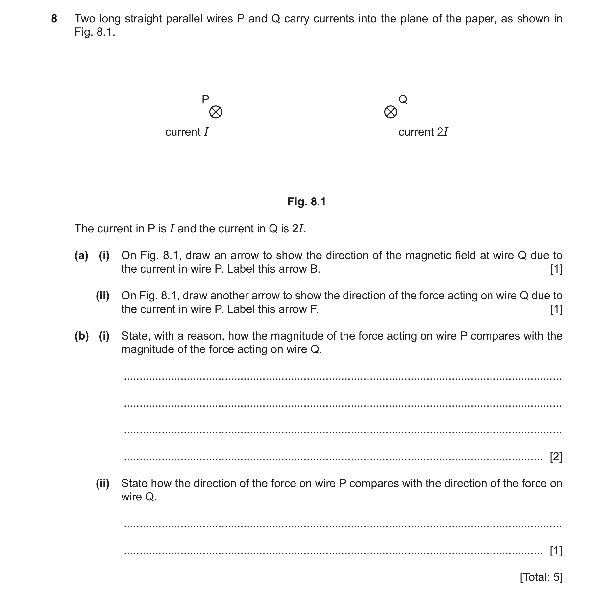
8 Two long straight parallel wires P and Q carry currents into the plane of the paper, as shown in Fig. 8.1. P Q current I current 2I Fig. 8.1 The current in P is I and the current in Q is 2I. (a) (i) On Fig. 8.1, draw an arrow to show the direction of the magnetic field at wire Q due to the current in wire P. Label this arrow B. [1] (ii) On Fig. 8.1, draw another arrow to show the direction of the force acting on wire Q due to the current in wire P. Label this arrow F. [1] (b) (i) State, with a reason, how the magnitude of the force acting on wire P compares with the magnitude of the force acting on wire Q. … … … … [2] (ii) State how the direction of the force on wire P compares with the direction of the force on wire Q. … … [1] [Total: 5]
5 marks
Mark scheme: 8(a)(i) arrow from Q pointing downwards, labelled B B1 8(a)(ii) arrow from Q pointing towards P, labelled F B1 8(b)(i) force is proportional to product of both currents (I and 2I) or Newton’s third law B1 forces are equal B1 8(b)(ii) opposite B1
This question in 9702/42 Oct/Nov 2021
Q9 · State the two conditions that must be satisfied for a copper wire, placed in a magnetic… 9702/42 May/June 2022
6 (a) State the two conditions that must be satisfied for a copper wire, placed in a magnetic field, to experience a magnetic force. 1 … … 2 … … [2] (b) A long air-cored solenoid is connected to a power supply, so that the solenoid creates a magnetic field. Fig. 6.1 shows a cross-section through the middle of the solenoid. Z section through solenoid wires Y W X Fig. 6.1 The direction of the magnetic field at point W is indicated by the arrow. Three other points are labelled X, Y and Z. (i) On Fig. 6.1, draw arrows to indicate the direction of the magnetic field at each of the points X, Y and Z. [3] (ii) Compare the magnitude of the flux density of the magnetic field: ● at X and at W … … ● at Y and at Z. … … [2] (c) Two long parallel current-carrying wires are placed near to each other in a vacuum. Explain why these wires exert a magnetic force on each other. You may draw a labelled diagram if you wish. … … … … [3] [Total: 10]
10 marks
Mark scheme: 6(a) there must be a current (in the wire) B1 (wire) must be at a non-zero angle to the magnetic field B1 6(b)(i) arrow from X pointing horizontally to the left B1 arrow from Y pointing diagonally upwards and to the left at about 45° B1 arrow from Z pointing horizontally to the right B1 6(b)(ii) (flux densities at W and X are approximately) equal B1 (flux density at) Y greater than (flux density at) Z B1 6(c) current in wire creates magnetic field around wire B1 (each) wire sits in the magnetic field created by the other B1 (for each wire,) current / wire is perpendicular to magnetic field (due to other wire), (so) experiences a (magnetic) force B1
This question in 9702/42 May/June 2022
Q10 · State what is meant by a magnetic field 9702/41 May/June 2023
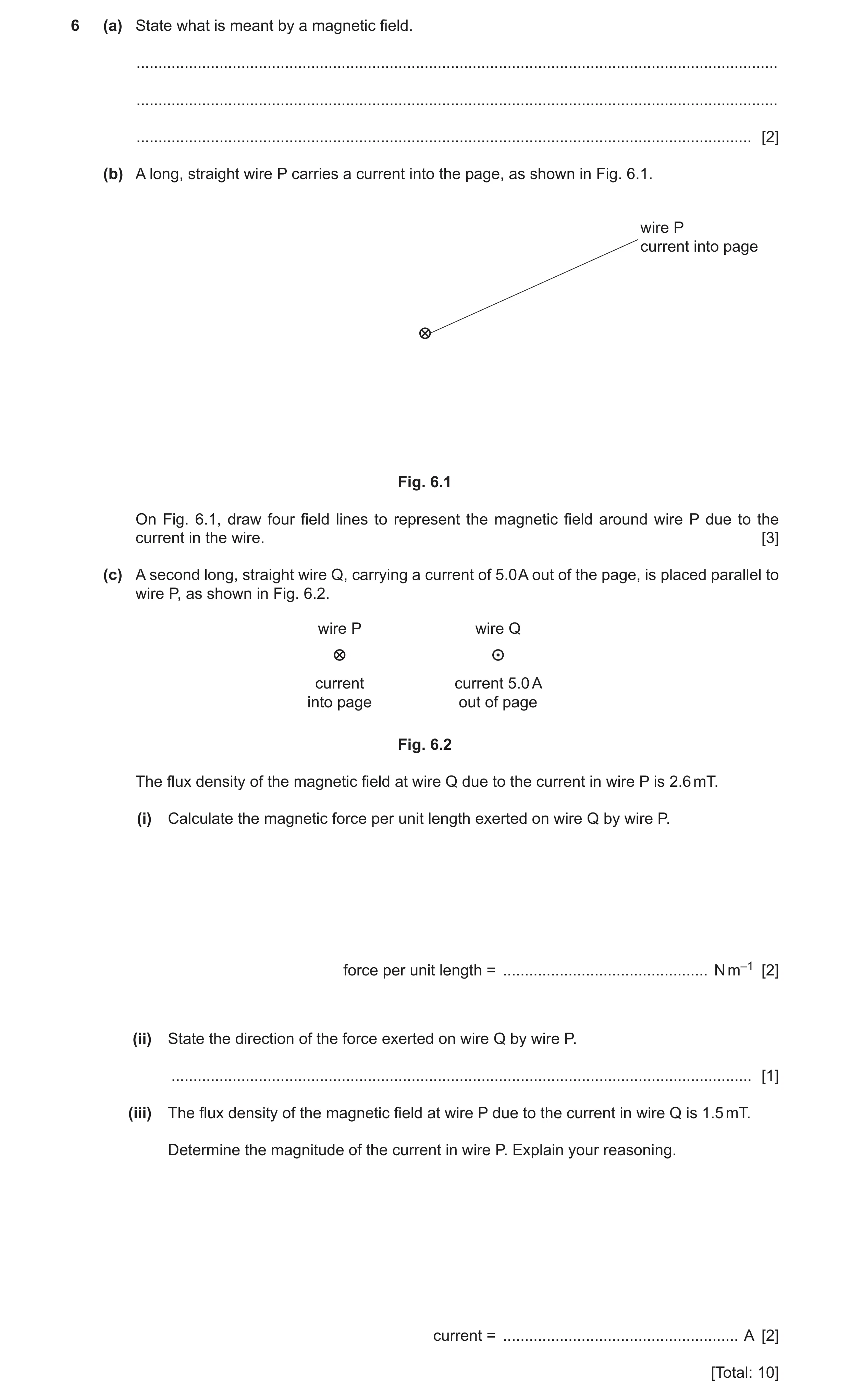
6 (a) State what is meant by a magnetic field. … … … [2] (b) A long, straight wire P carries a current into the page, as shown in Fig. 6.1. wire P current into page Fig. 6.1 On Fig. 6.1, draw four field lines to represent the magnetic field around wire P due to the current in the wire. [3] (c) A second long, straight wire Q, carrying a current of 5.0 A out of the page, is placed parallel to wire P, as shown in Fig. 6.2. wire P wire Q current current 5.0 A into page out of page Fig. 6.2 The flux density of the magnetic field at wire Q due to the current in wire P is 2.6 mT. (i) Calculate the magnetic force per unit length exerted on wire Q by wire P. force per unit length = … N m–1 [2] (ii) State the direction of the force exerted on wire Q by wire P. … [1] (iii) The flux density of the magnetic field at wire P due to the current in wire Q is 1.5 mT. Determine the magnitude of the current in wire P. Explain your reasoning. current = … A [2] [Total: 10]
10 marks
Mark scheme: 6(a) a region where a force acts on M1 a current-carrying conductor or a moving charge or a magnetic material / magnetic pole A1 6(b) concentric circles around the wire B1 spacing between circles increases with distance from wire B1 arrows showing direction of field is clockwise B1 6(c)(i) F = BIL C1 force per unit length = BI = 2.6 10–3 5.0 = 0.013 N m–1 A1 6(c)(ii) to the right B1 6(c)(iii) force (per unit length) has the same magnitude due to Newton’s 3rd law B1 0.013 = 1.5 10–3 I current = 8.7 A A1
This question in 9702/41 May/June 2023
Q11 · State what is meant by a magnetic field 9702/43 May/June 2023
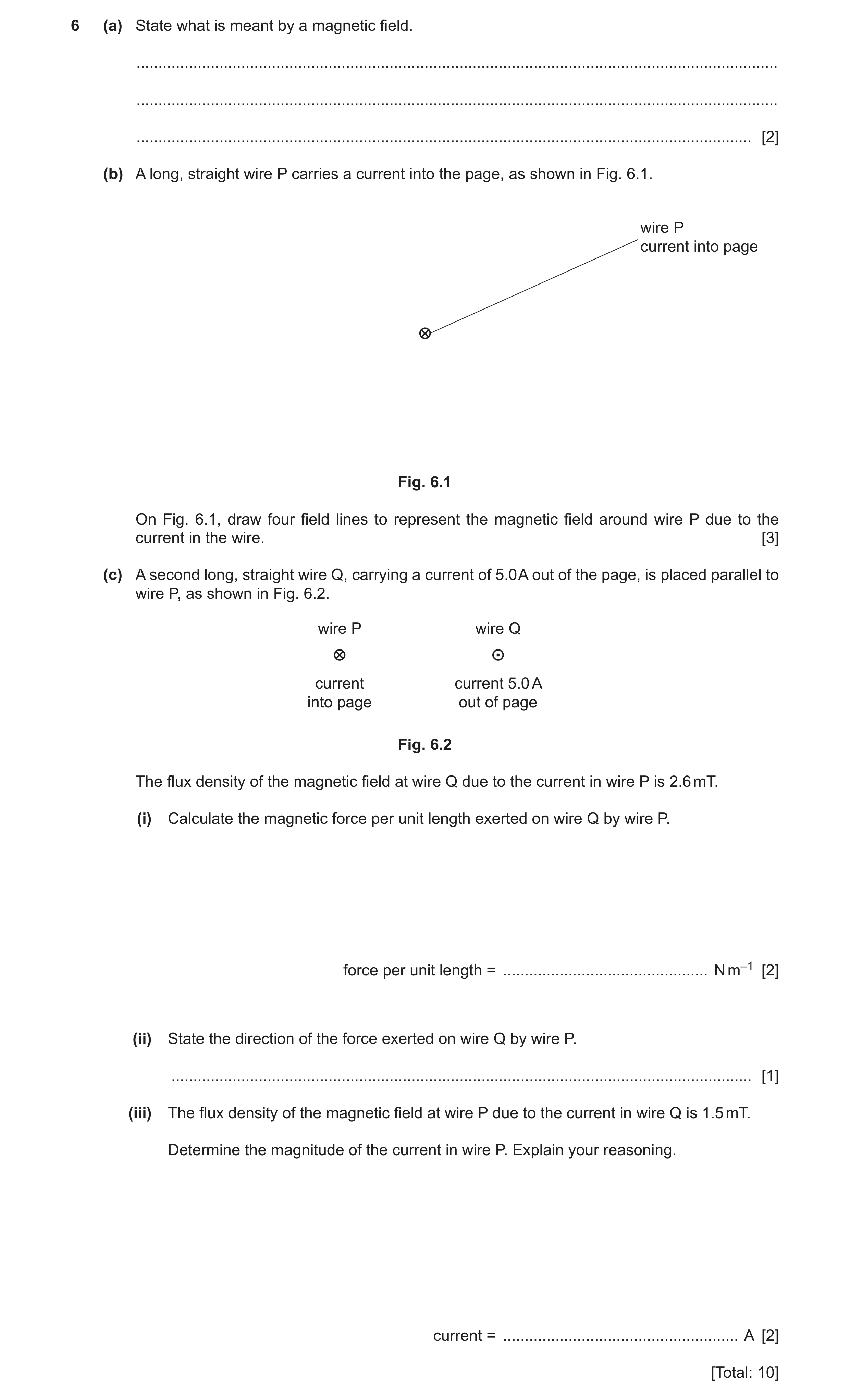
6 (a) State what is meant by a magnetic field. … … … [2] (b) A long, straight wire P carries a current into the page, as shown in Fig. 6.1. wire P current into page Fig. 6.1 On Fig. 6.1, draw four field lines to represent the magnetic field around wire P due to the current in the wire. [3] (c) A second long, straight wire Q, carrying a current of 5.0 A out of the page, is placed parallel to wire P, as shown in Fig. 6.2. wire P wire Q current current 5.0 A into page out of page Fig. 6.2 The flux density of the magnetic field at wire Q due to the current in wire P is 2.6 mT. (i) Calculate the magnetic force per unit length exerted on wire Q by wire P. force per unit length = … N m–1 [2] (ii) State the direction of the force exerted on wire Q by wire P. … [1] (iii) The flux density of the magnetic field at wire P due to the current in wire Q is 1.5 mT. Determine the magnitude of the current in wire P. Explain your reasoning. current = … A [2] [Total: 10]
10 marks
Mark scheme: 6(a) a region where a force acts on M1 a current-carrying conductor or a moving charge or a magnetic material / magnetic pole A1 6(b) concentric circles around the wire B1 spacing between circles increases with distance from wire B1 arrows showing direction of field is clockwise B1 6(c)(i) F = BIL C1 force per unit length = BI = 2.6 10–3 5.0 = 0.013 N m–1 A1 6(c)(ii) to the right B1 6(c)(iii) force (per unit length) has the same magnitude due to Newton’s 3rd law B1 0.013 = 1.5 10–3 I current = 8.7 A A1
This question in 9702/43 May/June 2023
Q12 · Define magnetic flux density 9702/41 Oct/Nov 2024
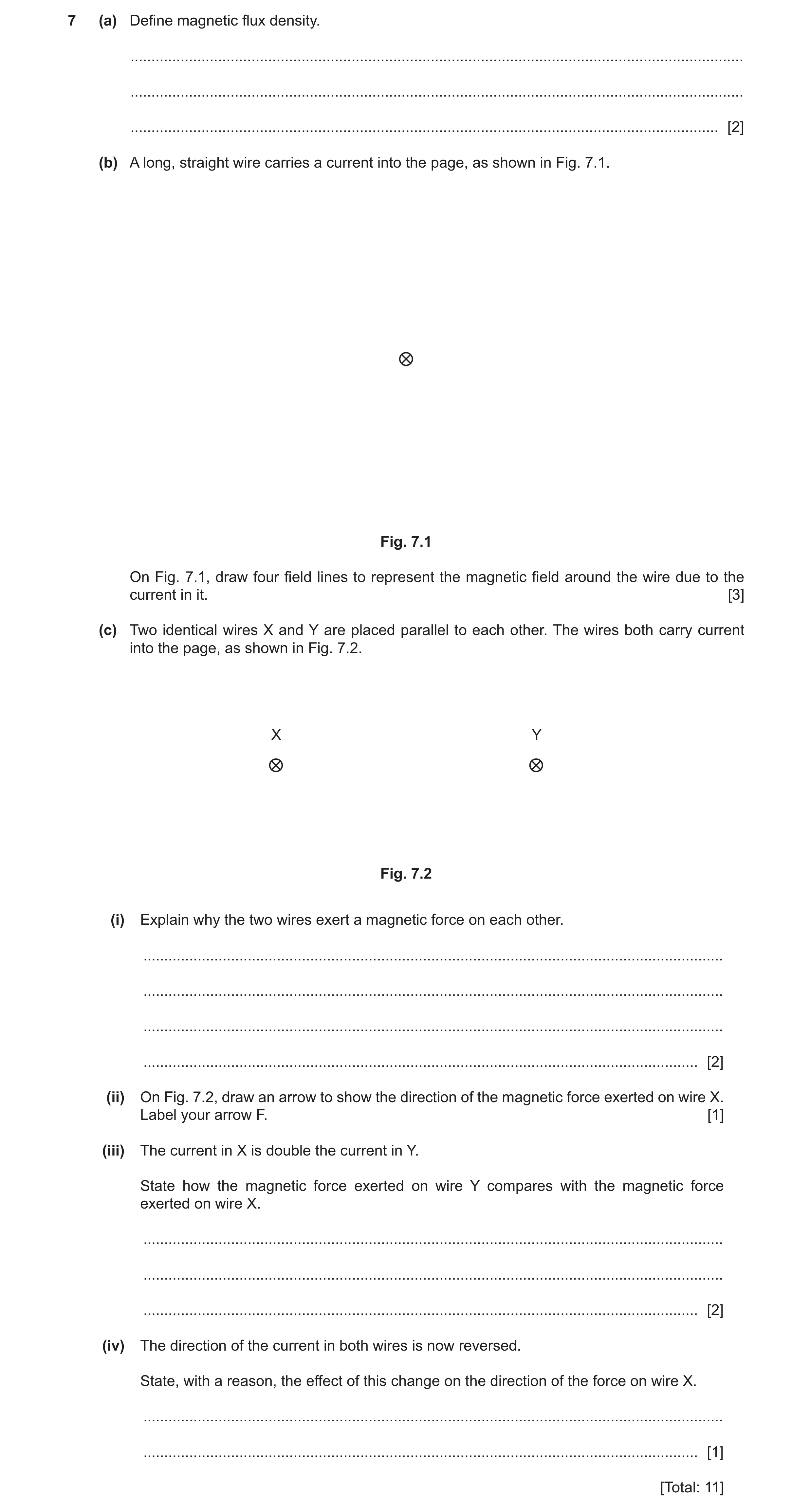
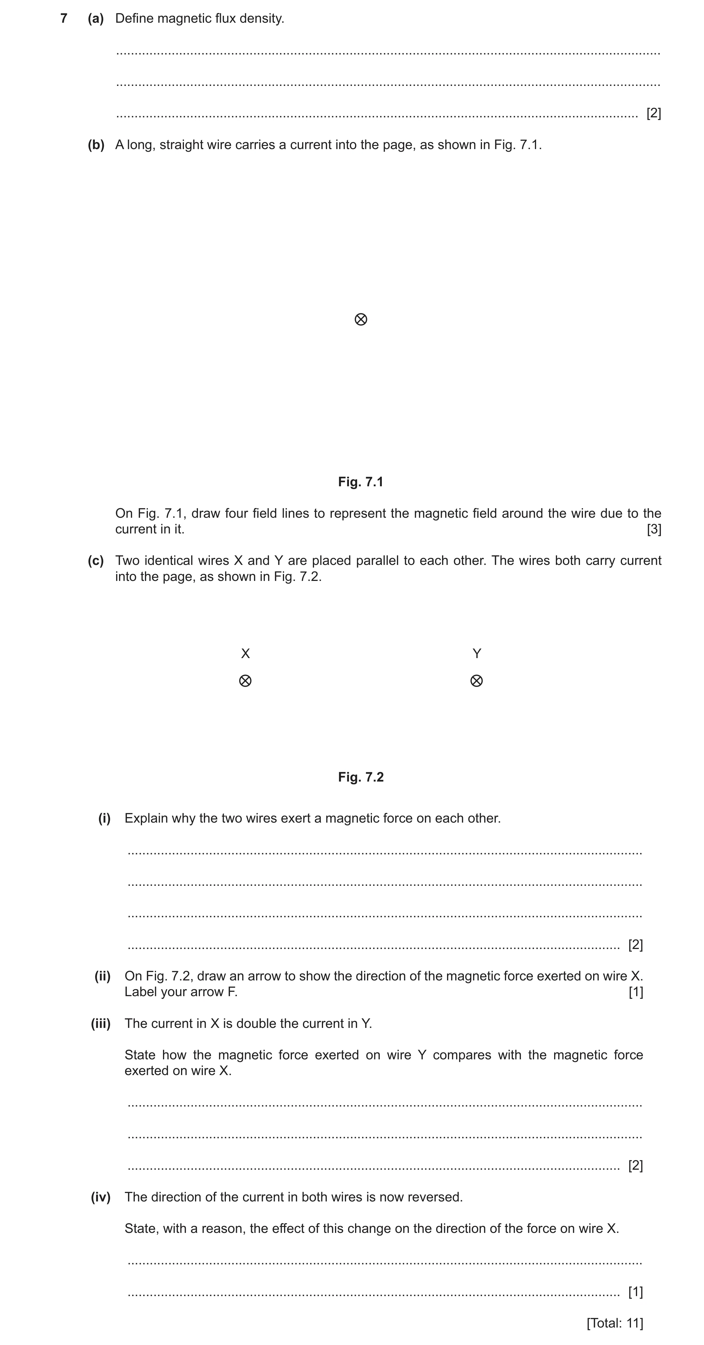
7 (a) Define magnetic flux density. … … … [2] (b) A long, straight wire carries a current into the page, as shown in Fig. 7.1. Fig. 7.1 On Fig. 7.1, draw four field lines to represent the magnetic field around the wire due to the current in it. [3] (c) Two identical wires X and Y are placed parallel to each other. The wires both carry current into the page, as shown in Fig. 7.2. X Y Fig. 7.2 (i) Explain why the two wires exert a magnetic force on each other. … … … … [2] (ii) On Fig. 7.2, draw an arrow to show the direction of the magnetic force exerted on wire X. Label your arrow F. [1] (iii) The current in X is double the current in Y. State how the magnetic force exerted on wire Y compares with the magnetic force exerted on wire X. … … … [2] (iv) The direction of the current in both wires is now reversed. State, with a reason, the effect of this change on the direction of the force on wire X. … … [1] [Total: 11]
11 marks
Mark scheme: 7(a) • force per unit length B2 • force per unit current • length / current perpendicular to field 1 mark for any two points, 2 marks for all three points 7(b) concentric circles around the wire (at least two circles needed) B1 spacing between circles increases with distance from wire (at least four circles needed) B1 arrows showing direction of field is clockwise B1 7(c)(i) (each) wire sits in the (magnetic) field created by the other B1 current (in one wire) is perpendicular to (magnetic) field (due to other wire) so (magnetic) force acts (on wire) B1 7(c)(ii) arrow drawn, starting from X and pointing towards Y, labelled F B1 7(c)(iii) (forces have) equal magnitudes B1 (forces are in) opposite directions B1 7(c)(iv) no change (in the direction of the force) since both the current in X and the field due to Y have reversed B1
This question in 9702/41 Oct/Nov 2024
Q13 · Define magnetic flux density 9702/43 Oct/Nov 2024
7 (a) Define magnetic flux density. … … … [2] (b) A long, straight wire carries a current into the page, as shown in Fig. 7.1. Fig. 7.1 On Fig. 7.1, draw four field lines to represent the magnetic field around the wire due to the current in it. [3] (c) Two identical wires X and Y are placed parallel to each other. The wires both carry current into the page, as shown in Fig. 7.2. X Y Fig. 7.2 (i) Explain why the two wires exert a magnetic force on each other. … … … … [2] (ii) On Fig. 7.2, draw an arrow to show the direction of the magnetic force exerted on wire X. Label your arrow F. [1] (iii) The current in X is double the current in Y. State how the magnetic force exerted on wire Y compares with the magnetic force exerted on wire X. … … … [2] (iv) The direction of the current in both wires is now reversed. State, with a reason, the effect of this change on the direction of the force on wire X. … … [1] [Total: 11]
11 marks
Mark scheme: 7(a) • force per unit length B2 • force per unit current • length / current perpendicular to field 1 mark for any two points, 2 marks for all three points 7(b) concentric circles around the wire (at least two circles needed) B1 spacing between circles increases with distance from wire (at least four circles needed) B1 arrows showing direction of field is clockwise B1 7(c)(i) (each) wire sits in the (magnetic) field created by the other B1 current (in one wire) is perpendicular to (magnetic) field (due to other wire) so (magnetic) force acts (on wire) B1 7(c)(ii) arrow drawn, starting from X and pointing towards Y, labelled F B1 7(c)(iii) (forces have) equal magnitudes B1 (forces are in) opposite directions B1 7(c)(iv) no change (in the direction of the force) since both the current in X and the field due to Y have reversed B1
This question in 9702/43 Oct/Nov 2024
 1 / 18
 2 / 18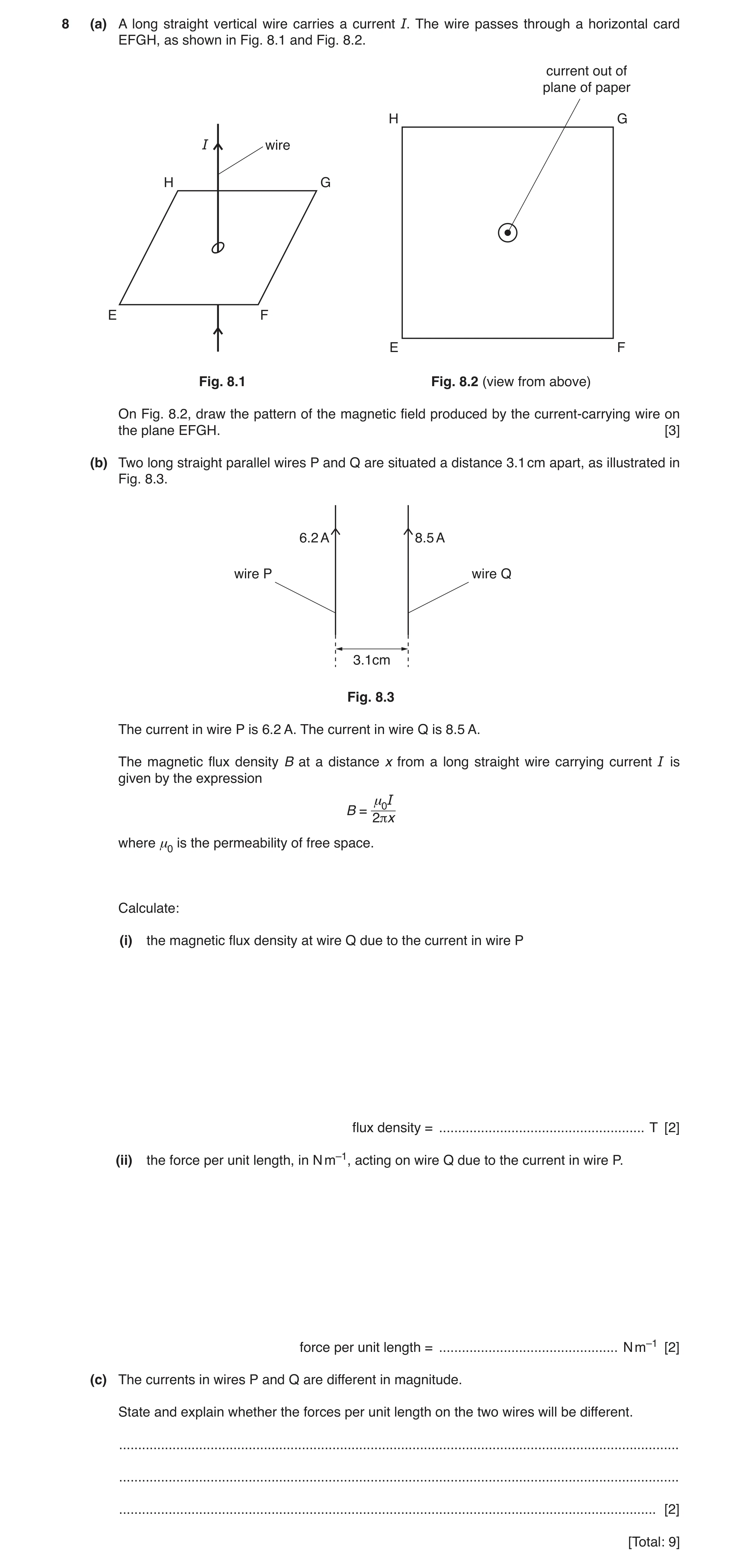
 11 / 18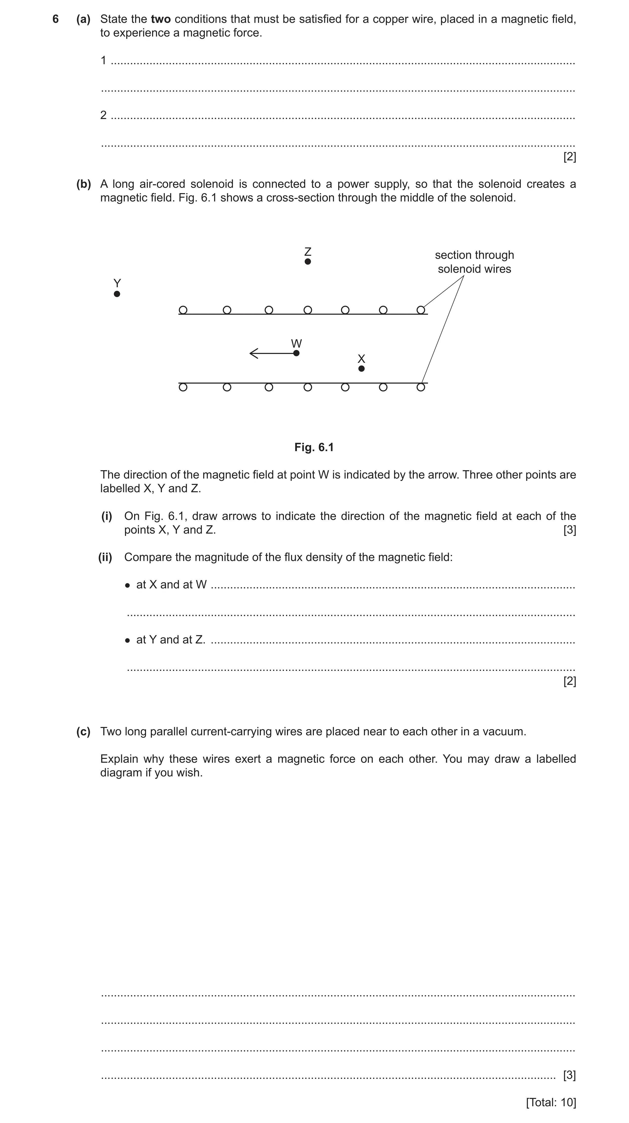
 8
8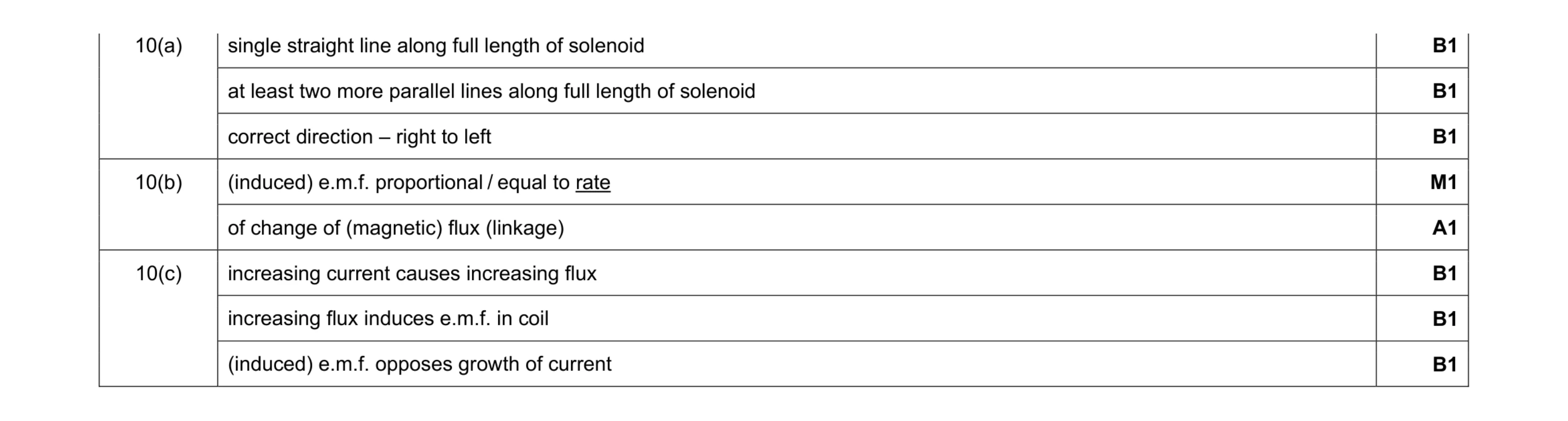 8
8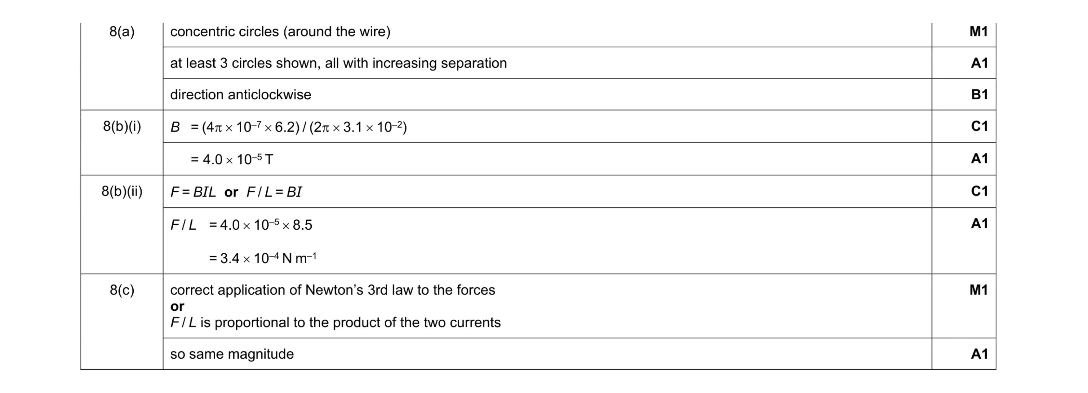 9
9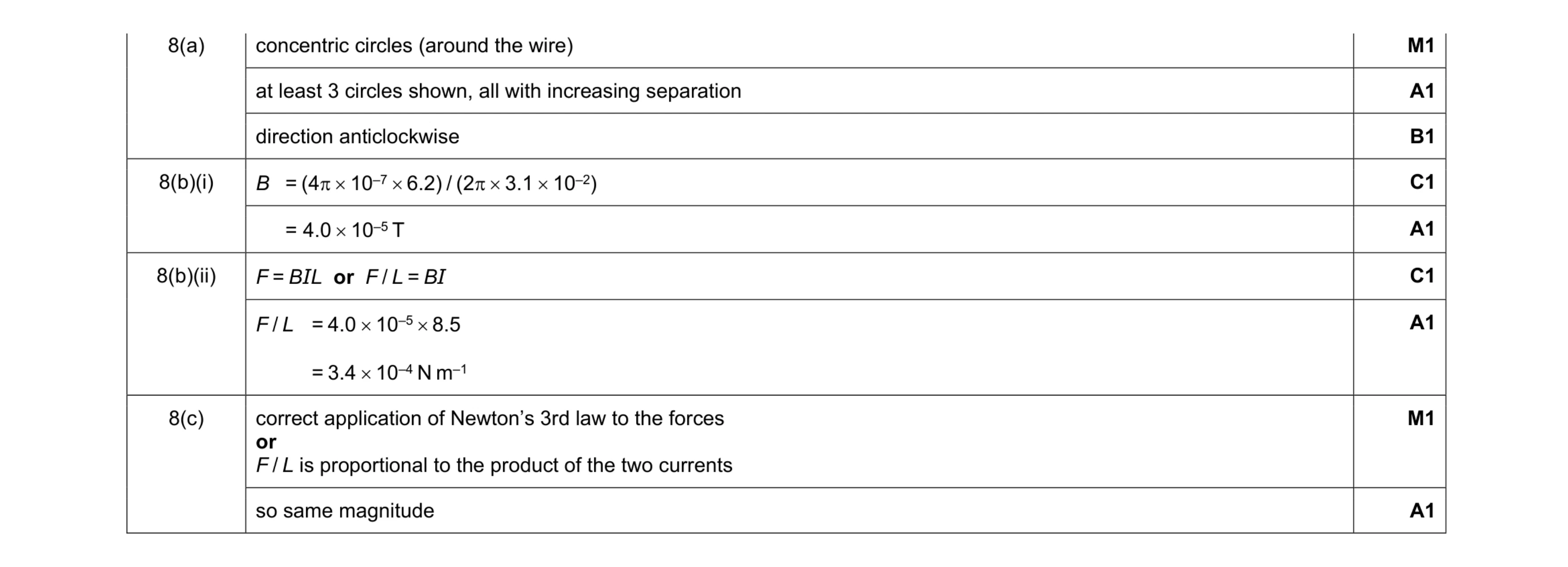 9
9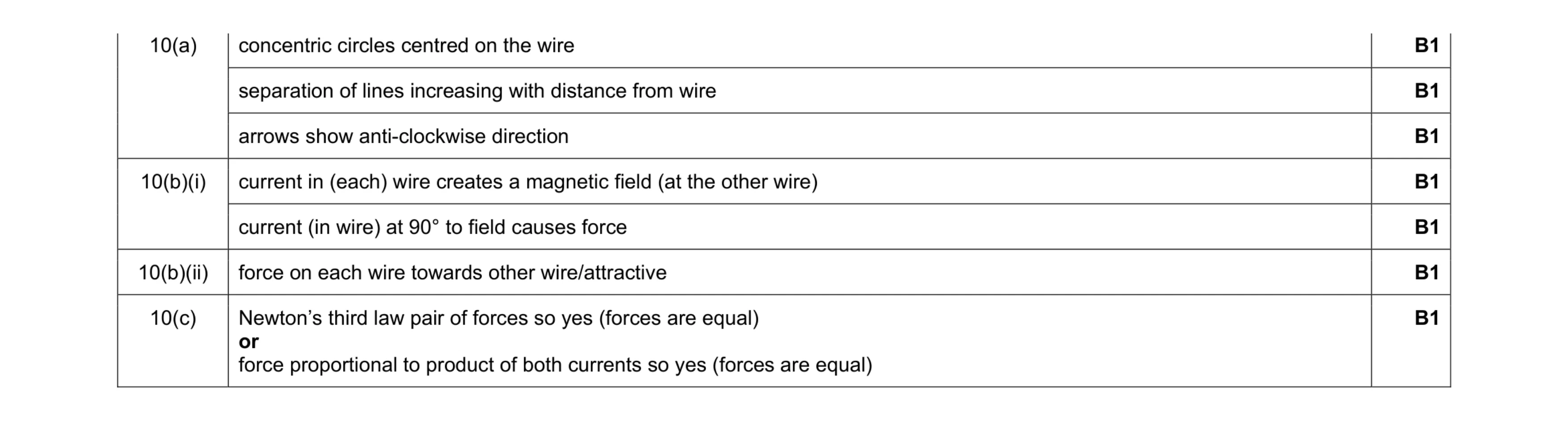 7
7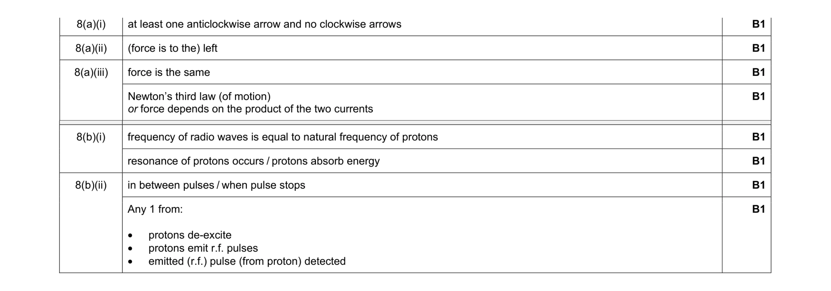 8
8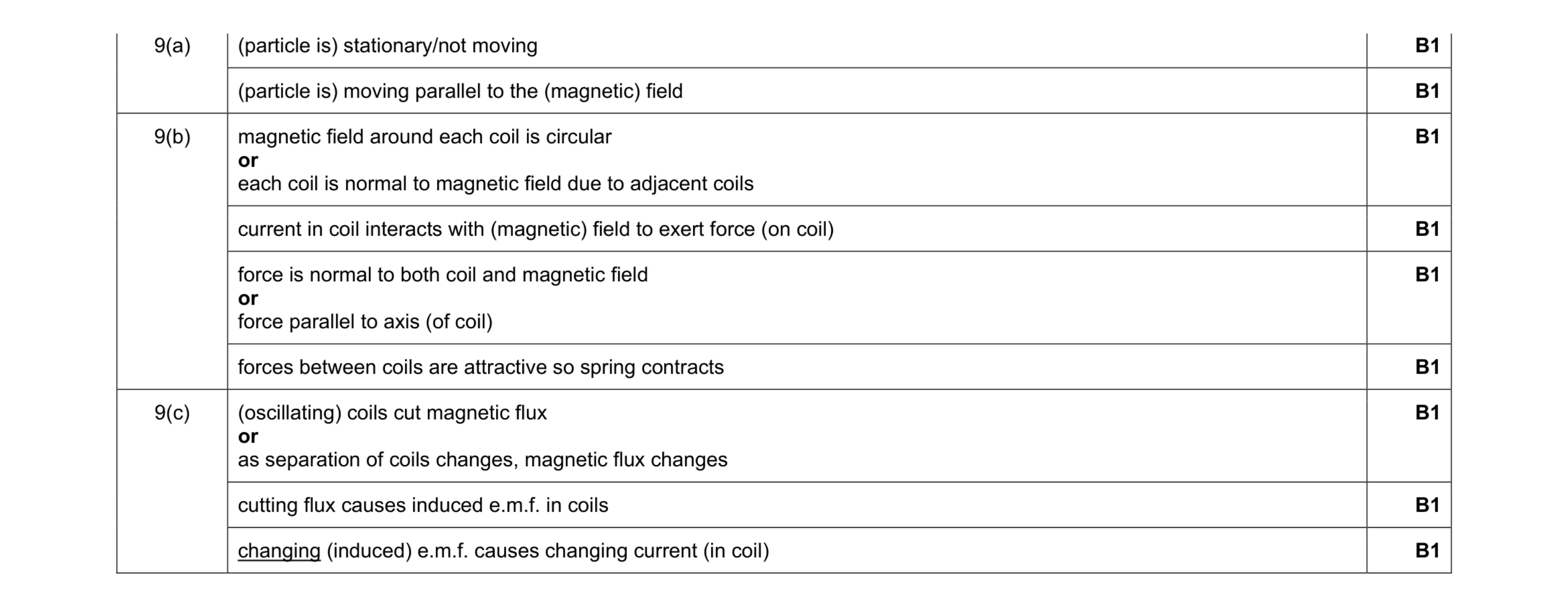 9
9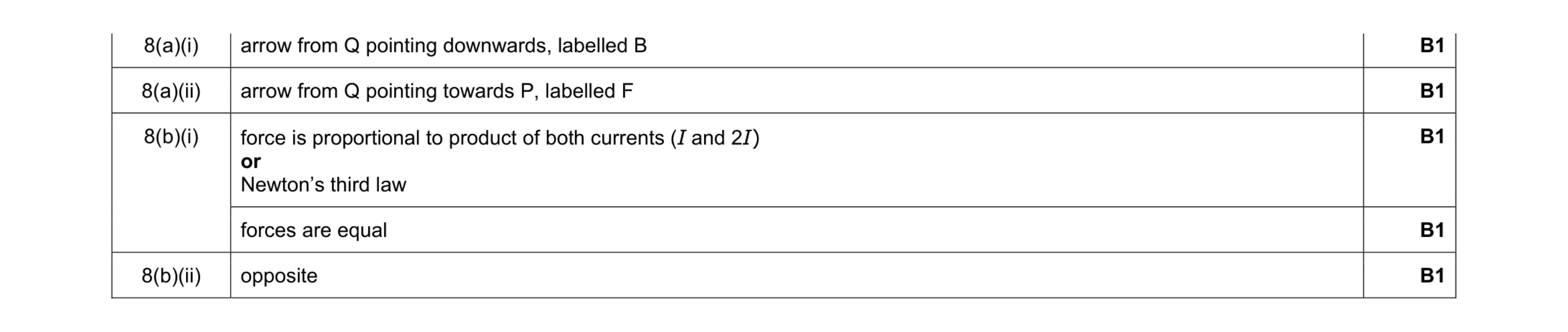 5
5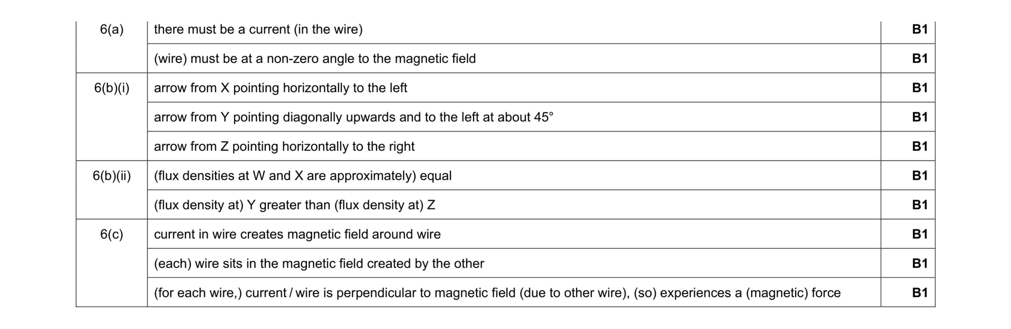 10
10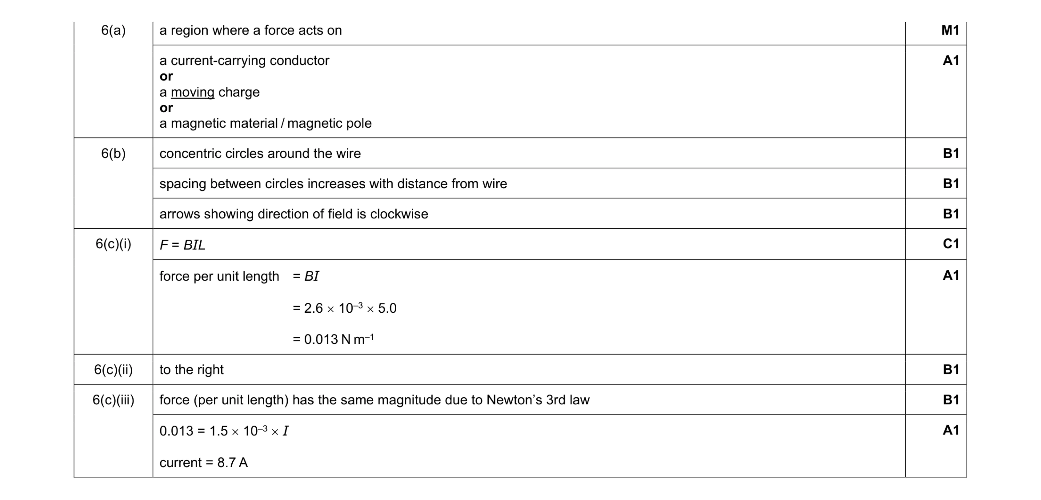 10
10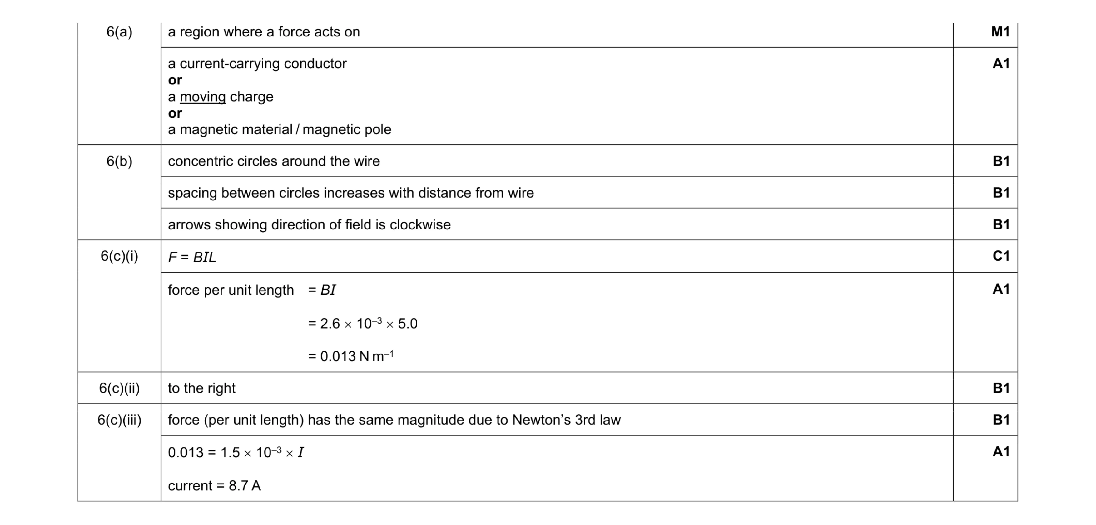 10
10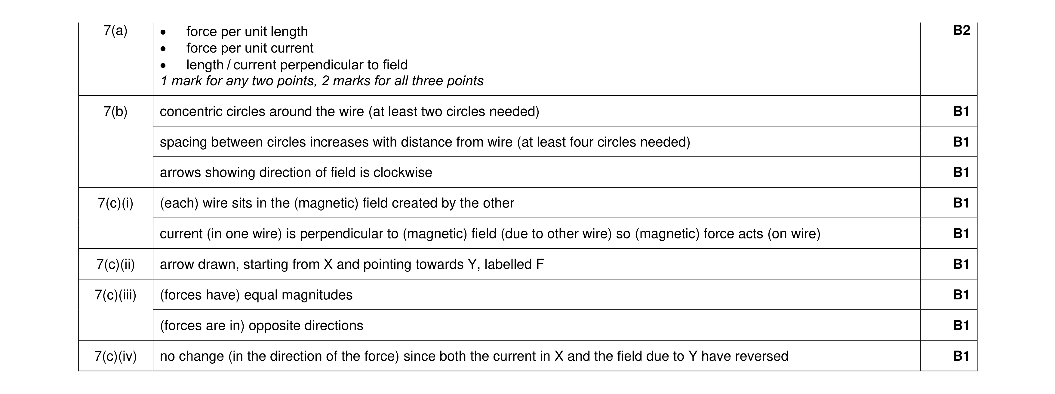 11
11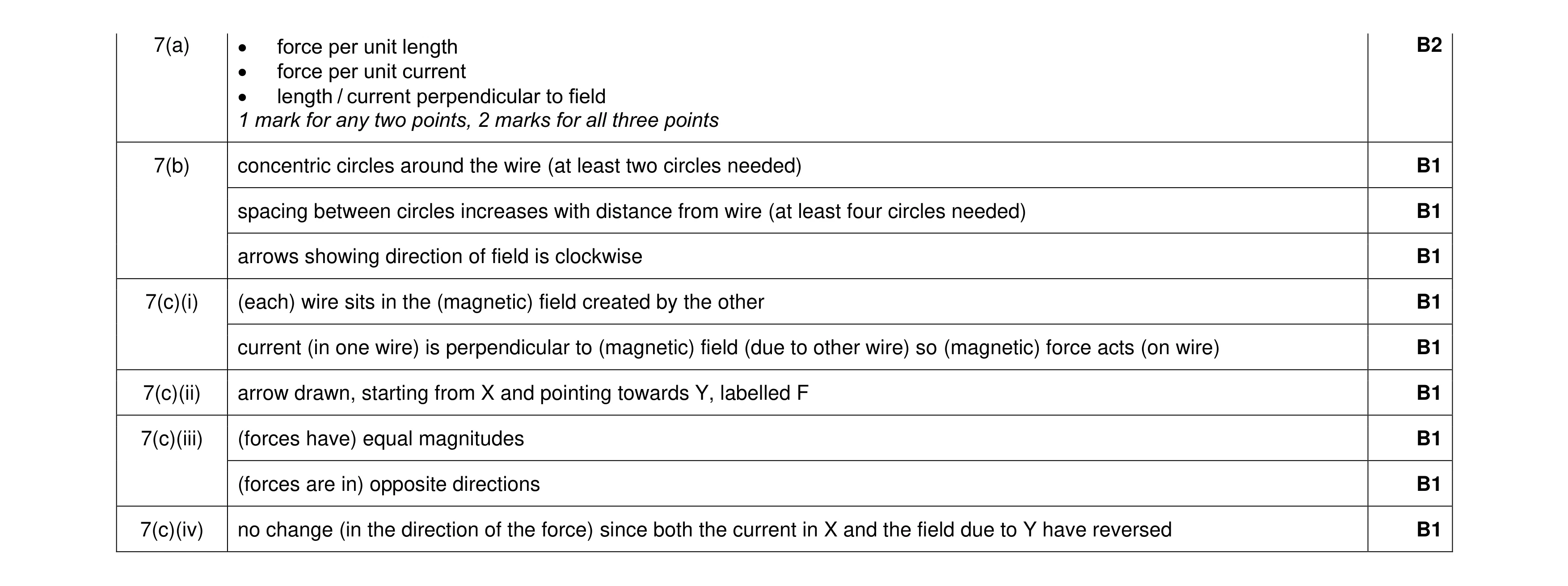 11
11