Cambridge IGCSE Design and Technology 0445 — 2024 Oct/Nov Paper 3 · Variant 1
0445/31/O/N/24 · 13 questions · 50 marks · 60 min
The question paper and its mark scheme, free to read here and free to download. This is Cambridge’s own paper, exactly as it was sat.
Question paper24 pages
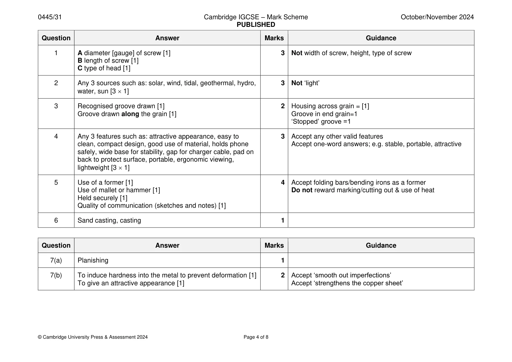
Mark scheme8 pages
Answers below. Sit the paper first if you are practising.

Questions as text
Q1 · The label from a box of wood screws
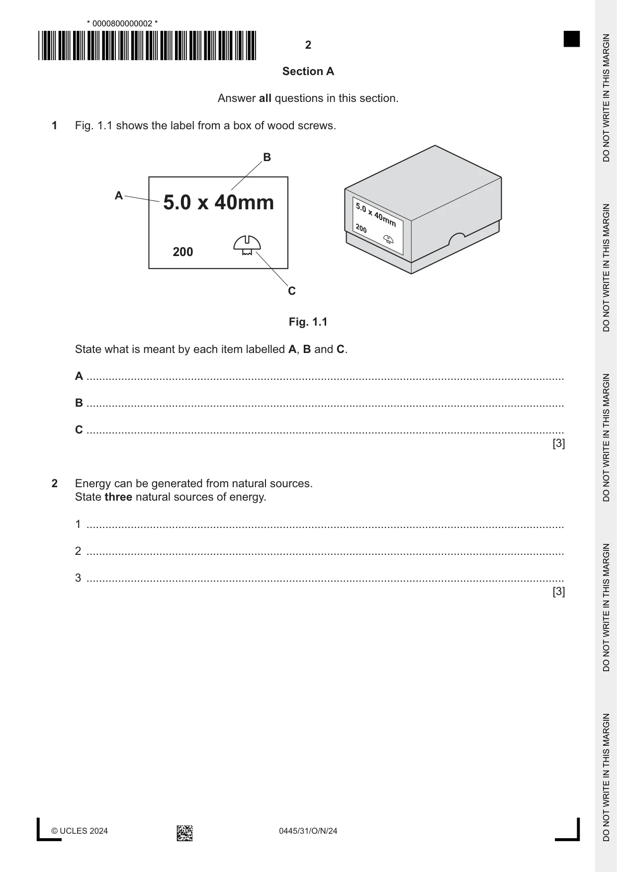
1 Fig. 1.1 shows the label from a box of wood screws. B A 5.0 x 40mm 5.0 x 40mm 200 200 C Fig. 1.1 State what is meant by each item labelled A, B and C. A ....................................................................................................................................................... B ....................................................................................................................................................... C ....................................................................................................................................................... [3]
Mark scheme: Question Answer Marks Guidance 1 A diameter [gauge] of screw [1] 3 Not width of screw, height, type of screw B length of screw [1] C type of head [1]
Q2 · Energy can be generated from natural sources
2 Energy can be generated from natural sources. State three natural sources of energy. 1 ....................................................................................................................................................... 2 ....................................................................................................................................................... 3 ....................................................................................................................................................... [3]
Mark scheme: 2 Any 3 sources such as: solar, wind, tidal, geothermal, hydro, 3 Not ‘light’ water, sun [3 1]
Q3 · A block of softwood 20 mm thick
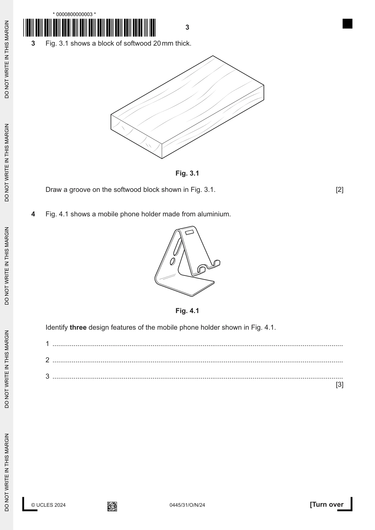
3 Fig. 3.1 shows a block of softwood 20 mm thick. Fig. 3.1 Draw a groove on the softwood block shown in Fig. 3.1. [2]
Mark scheme: 3 Recognised groove drawn [1] 2 Housing across grain = [1] Groove drawn along the grain [1] Groove in end grain=1 ‘Stopped’ groove =1
Q4 · A mobile phone holder made from aluminium
4 Fig. 4.1 shows a mobile phone holder made from aluminium. Fig. 4.1 Identify three design features of the mobile phone holder shown in Fig. 4.1. 1 ....................................................................................................................................................... 2 ....................................................................................................................................................... 3 ....................................................................................................................................................... [3]
Mark scheme: 4 Any 3 features such as: attractive appearance, easy to 3 Accept any other valid features clean, compact design, good use of material, holds phone Accept one-word answers; e.g. stable, portable, attractive safely, wide base for stability, gap for charger cable, pad on back to protect surface, portable, ergonomic viewing, lightweight [3 1]
Q5 · A sign holder made from 1.5 mm thick mild steel sheet
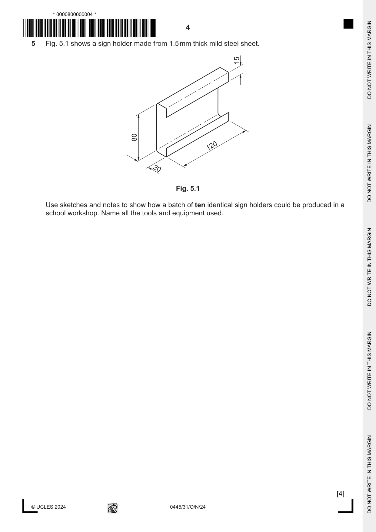
5 Fig. 5.1 shows a sign holder made from 1.5 mm thick mild steel sheet. 15 80 120 20 Fig. 5.1 Use sketches and notes to show how a batch of ten identical sign holders could be produced in a school workshop. Name all the tools and equipment used. [4]
Mark scheme: 5 Use of a former [1] 4 Accept folding bars/bending irons as a former Use of mallet or hammer [1] Do not reward marking/cutting out & use of heat Held securely [1] Quality of communication (sketches and notes) [1]
Q6 · A split pattern made of wood
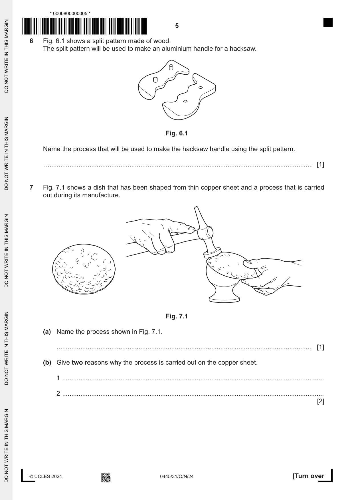
6 Fig. 6.1 shows a split pattern made of wood. The split pattern will be used to make an aluminium handle for a hacksaw. Fig. 6.1 Name the process that will be used to make the hacksaw handle using the split pattern. .................................................................................................................................................... [1]
Mark scheme: 6 Sand casting, casting 1
Q7 · A dish that has been shaped from thin copper sheet and a process that is carried out…
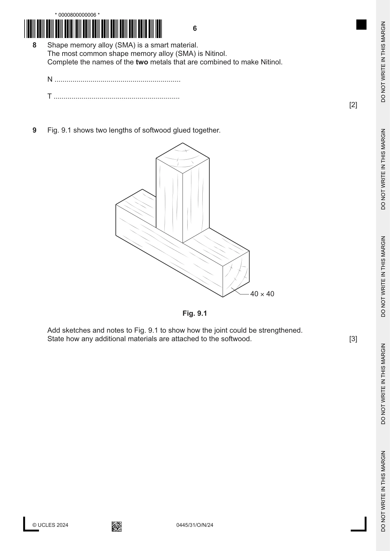
7 Fig. 7.1 shows a dish that has been shaped from thin copper sheet and a process that is carried out during its manufacture. Fig. 7.1 (a) Name the process shown in Fig. 7.1. ............................................................................................................................................. [1] (b) Give two reasons why the process is carried out on the copper sheet. 1 ................................................................................................................................................ 2 ................................................................................................................................................ [2]
Mark scheme: 7(a) Planishing 1 7(b) To induce hardness into the metal to prevent deformation [1] 2 Accept ‘smooth out imperfections’ To give an attractive appearance [1] Accept ‘strengthens the copper sheet’
Q8 · Shape memory alloy (SMA) is a smart material
8 Shape memory alloy (SMA) is a smart material. The most common shape memory alloy (SMA) is Nitinol. Complete the names of the two metals that are combined to make Nitinol. N ............................................................... T ............................................................... [2]
Mark scheme: 8 Nickel Titanium [2 1] 2
Q9 · Two lengths of softwood glued together
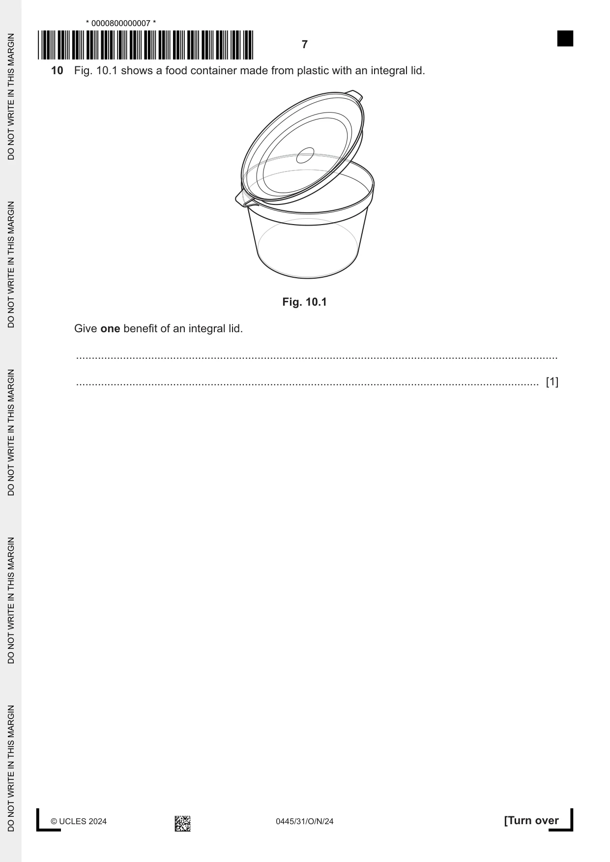
9 Fig. 9.1 shows two lengths of softwood glued together. 40 × 40 Fig. 9.1 Add sketches and notes to Fig. 9.1 to show how the joint could be strengthened. State how any additional materials are attached to the softwood. [3]
Mark scheme: 9 Blocks or brackets added to the 2 corners [0 – 2] 3 The joint must remain assembled Both corners/faces must be strengthened OR One face strengthened = [1] Accept nails or screws inserted underneath or at an angle ‘Plates’ attached to the front and back faces [0 – 2] above =1 Method of attaching additional materials [1]
Q10 · A food container made from plastic with an integral lid
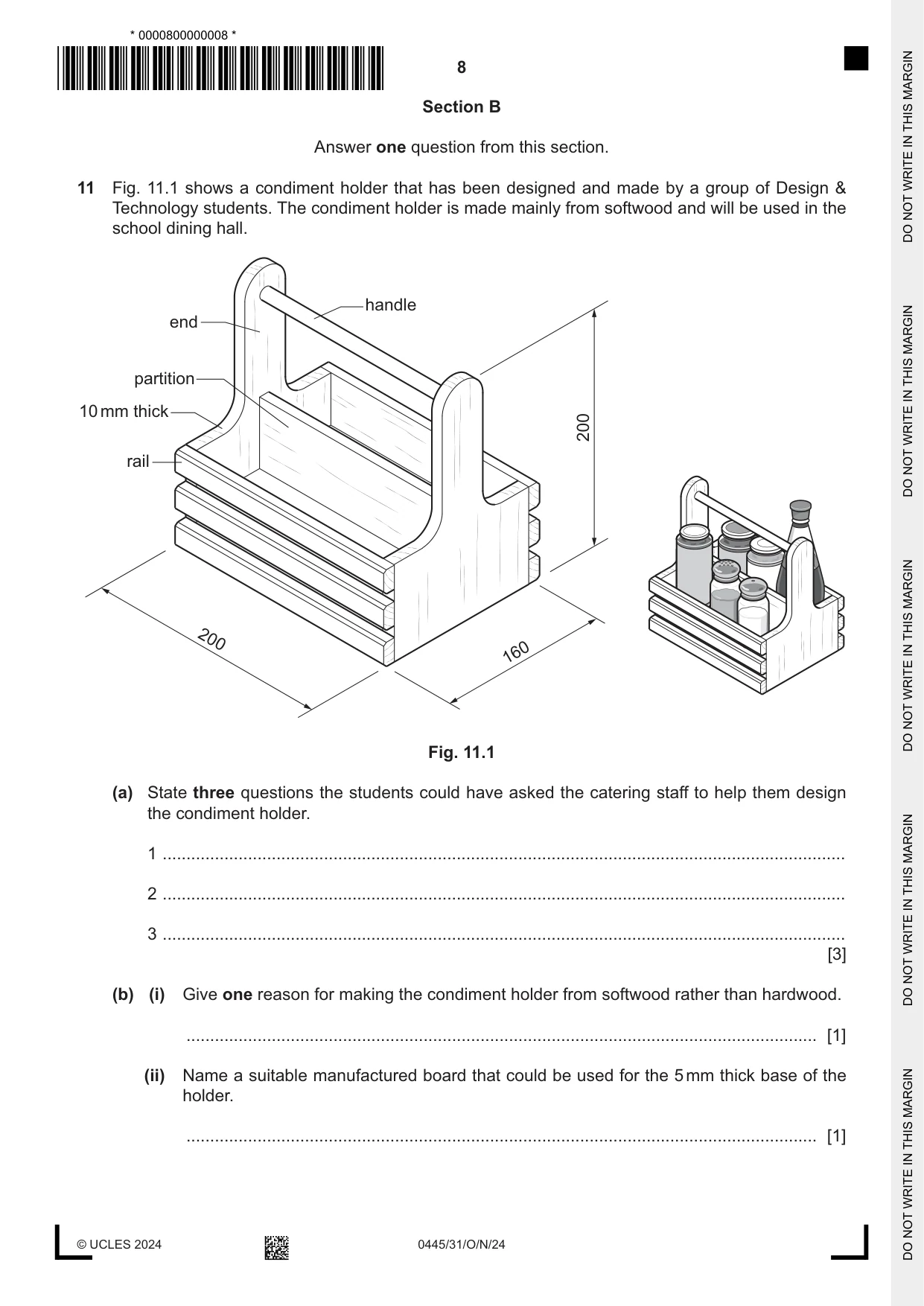
10 Fig. 10.1 shows a food container made from plastic with an integral lid. Fig. 10.1 Give one benefit of an integral lid. .......................................................................................................................................................... .................................................................................................................................................... [1]
Mark scheme: 10 The lid is not a separate part of the container as it is 1 Accept any other valid benefit attached, lid cannot be lost or misplaced, the lid is easy to open and close
Q11 · A condiment holder that has been designed and made by a group of Design & Technology…
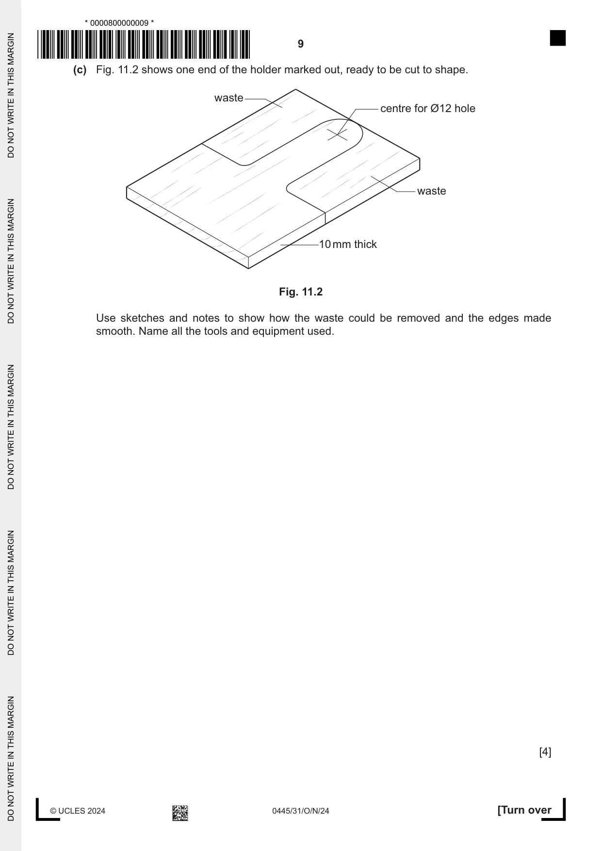
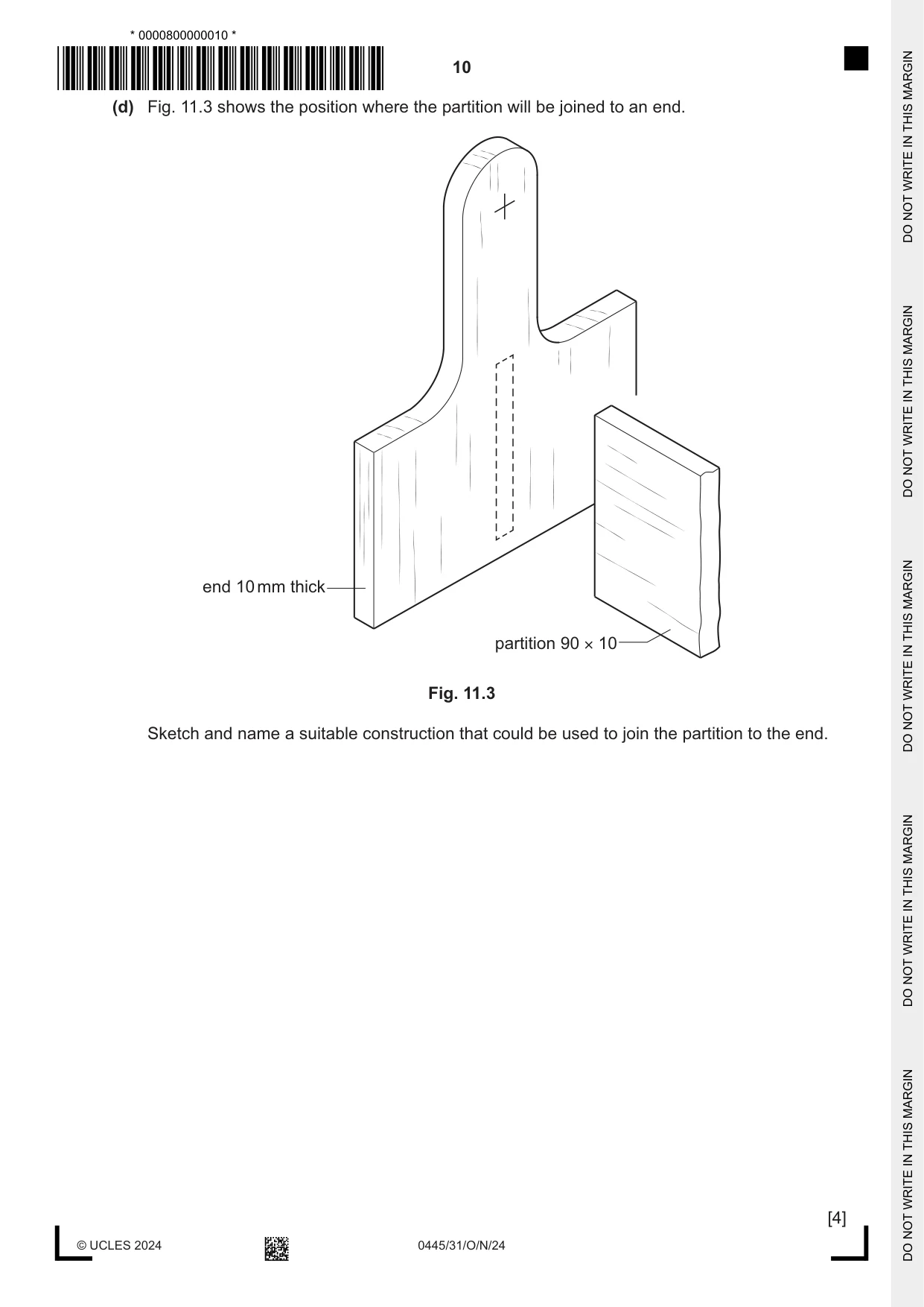
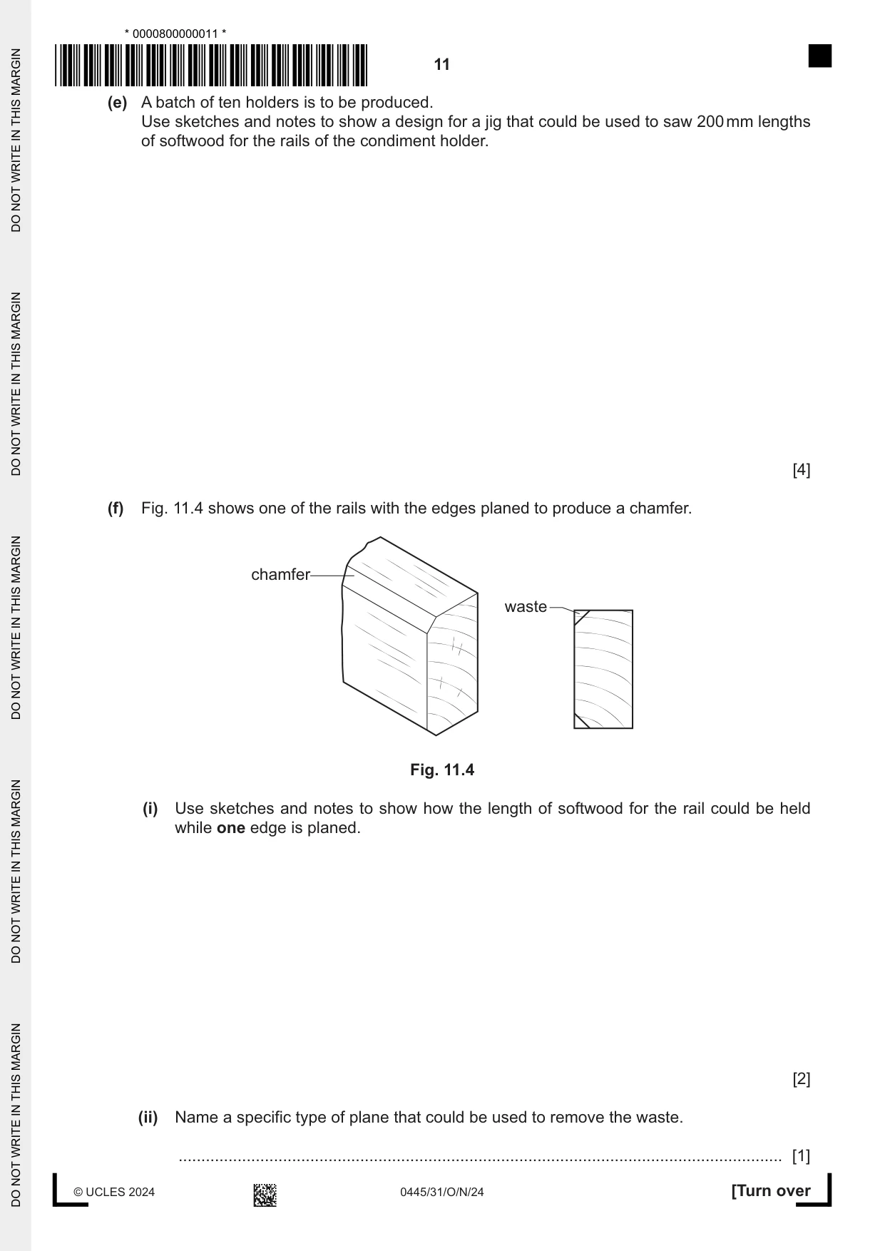
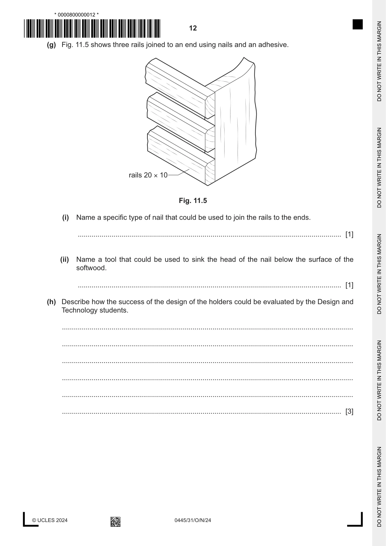
11 Fig. 11.1 shows a condiment holder that has been designed and made by a group of Design & Technology students. The condiment holder is made mainly from softwood and will be used in the school dining hall. handle end partition 10 mm thick 200 rail 200 160 Fig. 11.1 (a) State three questions the students could have asked the catering staff to help them design the condiment holder. 1 ................................................................................................................................................ 2 ................................................................................................................................................ 3 ................................................................................................................................................ [3] (b) (i) Give one reason for making the condiment holder from softwood rather than hardwood. ..................................................................................................................................... [1] (ii) Name a suitable manufactured board that could be used for the 5 mm thick base of the holder. ..................................................................................................................................... [1] (c) Fig. 11.2 shows one end of the holder marked out, ready to be cut to shape. waste centre for Ø12 hole waste 10 mm thick Fig. 11.2 Use sketches and notes to show how the waste could be removed and the edges made smooth. Name all the tools and equipment used. [4] (d) Fig. 11.3 shows the position where the partition will be joined to an end. end 10 mm thick partition 90 × 10 Fig. 11.3 Sketch and name a suitable construction that could be used to join the partition to the end. [4] (e) A batch of ten holders is to be produced. Use sketches and notes to show a design for a jig that could be used to saw 200 mm lengths of softwood for the rails of the condiment holder. [4] (f) Fig. 11.4 shows one of the rails with the edges planed to produce a chamfer. chamfer waste Fig. 11.4 (i) Use sketches and notes to show how the length of softwood for the rail could be held while one edge is planed. [2] (ii) Name a specific type of plane that could be used to remove the waste. ..................................................................................................................................... [1] (g) Fig. 11.5 shows three rails joined to an end using nails and an adhesive. rails 20 × 10 Fig. 11.5 (i) Name a specific type of nail that could be used to join the rails to the ends. ..................................................................................................................................... [1] (ii) Name a tool that could be used to sink the head of the nail below the surface of the softwood. ..................................................................................................................................... [1] (h) Describe how the success of the design of the holders could be evaluated by the Design and Technology students. ................................................................................................................................................... ................................................................................................................................................... ................................................................................................................................................... ................................................................................................................................................... ................................................................................................................................................... ............................................................................................................................................. [3]
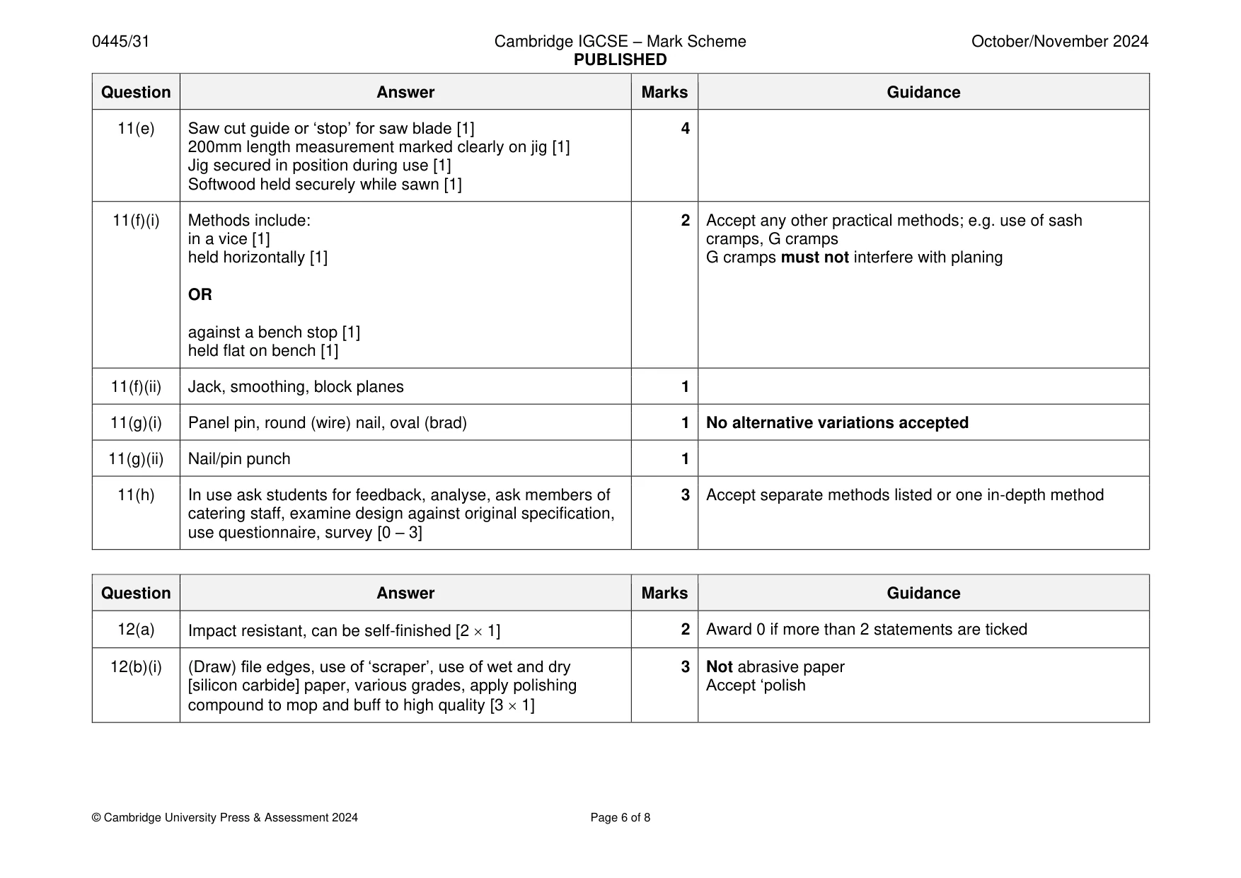
Mark scheme: 11(a) Any 3 questions such as: how many reqd. what type of 3 Accept any other valid questions condiments, how many different condiments in each holder, where will they be used/stored/cleaned, portable, how large could it be, budget, weight of condiments, water resistant [3 1] 11(b)(i) Softwoods are more readily available, cheaper 1 Accept any other valid reasons Not easier to work, more attractive 11(b)(ii) Plywood, MDF, hardboard 1 Not blockboard 11(c) Cut out using coping, Hegner, scroll, band, jig saws [1] 4 Sketches of tools used to cut and file reqd. Use of files to smooth sawn edges [1] Use of glasspaper to smooth sawn edges [1] Accept ‘abrasive paper’ Quality of communication [sketches and notes] [1] 11(d) Dowel, mortise and tenon, housing joint, domino, biscuit 4 Do not accept use of glue only named [1] Technical accuracy of construction: proportion, orientation [0 – 3] 11(e) Saw cut guide or ‘stop’ for saw blade [1] 4 200mm length measurement marked clearly on jig [1] Jig secured in position during use [1] Softwood held securely while sawn [1] 11(f)(i) Methods include: 2 Accept any other practical methods; e.g. use of sash in a vice [1] cramps, G cramps held horizontally [1] G cramps must not interfere with planing OR against a bench stop [1] held flat on bench [1] 11(f)(ii) Jack, smoothing, block planes 1 11(g)(i) Panel pin, round (wire) nail, oval (brad) 1 No alternative variations accepted 11(g)(ii) Nail/pin punch 1 11(h) In use ask students for feedback, analyse, ask members of 3 Accept separate methods listed or one in-depth method catering staff, examine design against original specification, use questionnaire, survey [0 – 3]
Q12 · Views of an incomplete design for a freestanding clock made from acrylic
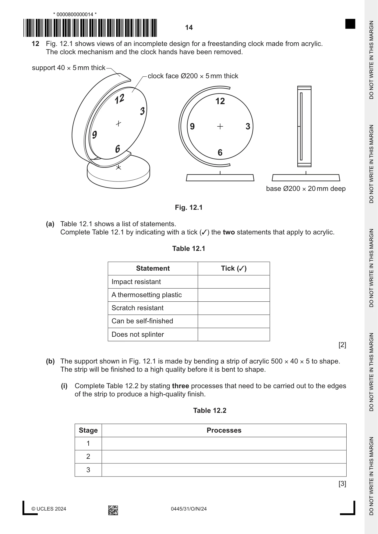
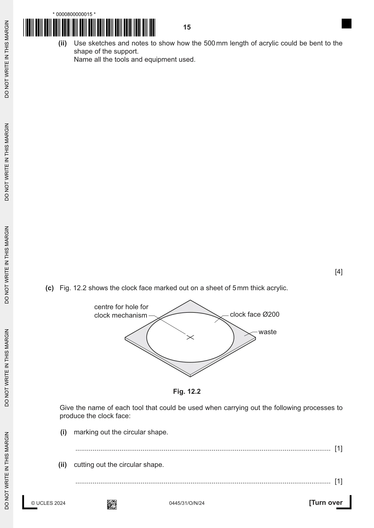
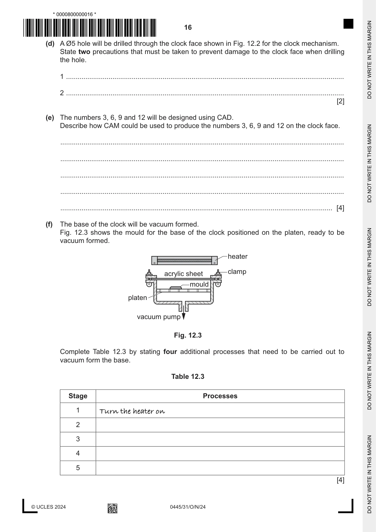
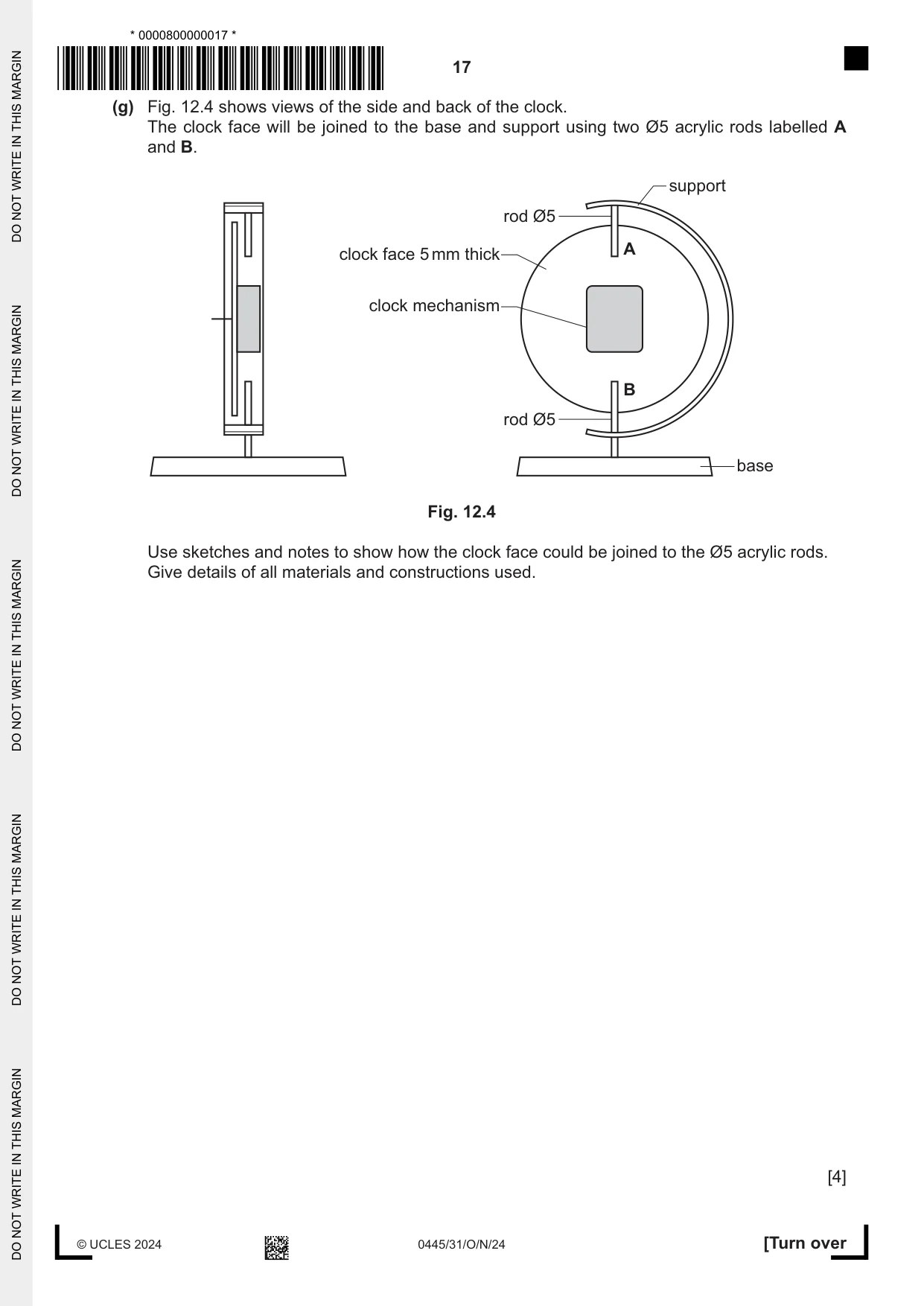
12 Fig. 12.1 shows views of an incomplete design for a freestanding clock made from acrylic. The clock mechanism and the clock hands have been removed. support 40 × 5 mm thick clock face Ø200 × 5 mm thick 12 12 3 9 3 9 6 6 base Ø200 × 20 mm deep Fig. 12.1 (a) Table 12.1 shows a list of statements. Complete Table 12.1 by indicating with a tick (3) the two statements that apply to acrylic. Table 12.1 Statement Tick (3) Impact resistant A thermosetting plastic Scratch resistant Can be self-finished Does not splinter [2] (b) The support shown in Fig. 12.1 is made by bending a strip of acrylic 500 × 40 × 5 to shape. The strip will be finished to a high quality before it is bent to shape. (i) Complete Table 12.2 by stating three processes that need to be carried out to the edges of the strip to produce a high-quality finish. Table 12.2 Stage Processes 1 2 3 [3] (ii) Use sketches and notes to show how the 500 mm length of acrylic could be bent to the shape of the support. Name all the tools and equipment used. [4] (c) Fig. 12.2 shows the clock face marked out on a sheet of 5 mm thick acrylic. centre for hole for clock mechanism clock face Ø200 waste Fig. 12.2 Give the name of each tool that could be used when carrying out the following processes to produce the clock face: (i) marking out the circular shape. ..................................................................................................................................... [1] (ii) cutting out the circular shape. ..................................................................................................................................... [1] (d) A Ø5 hole will be drilled through the clock face shown in Fig. 12.2 for the clock mechanism. State two precautions that must be taken to prevent damage to the clock face when drilling the hole. 1 ................................................................................................................................................ 2 ................................................................................................................................................ [2] (e) The numbers 3, 6, 9 and 12 will be designed using CAD. Describe how CAM could be used to produce the numbers 3, 6, 9 and 12 on the clock face. ................................................................................................................................................... ................................................................................................................................................... ................................................................................................................................................... ................................................................................................................................................... ............................................................................................................................................. [4] (f) The base of the clock will be vacuum formed. Fig. 12.3 shows the mould for the base of the clock positioned on the platen, ready to be vacuum formed. heater clamp acrylic sheet mould platen vacuum pump Fig. 12.3 Complete Table 12.3 by stating four additional processes that need to be carried out to vacuum form the base. Table 12.3 Stage Processes 1 Turn the heater on 2 3 4 5 [4] (g) Fig. 12.4 shows views of the side and back of the clock. The clock face will be joined to the base and support using two Ø5 acrylic rods labelled A and B. support rod Ø5 A clock face 5 mm thick clock mechanism B rod Ø5 base Fig. 12.4 Use sketches and notes to show how the clock face could be joined to the Ø5 acrylic rods. Give details of all materials and constructions used. [4]
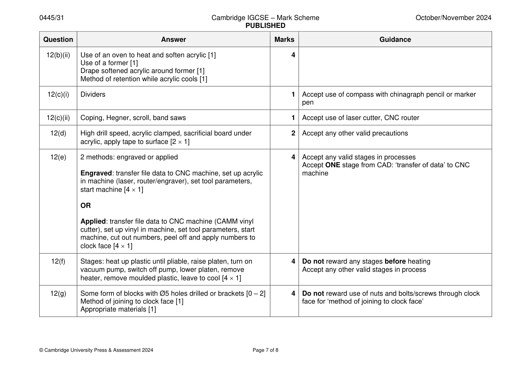
Mark scheme: 12(a) Impact resistant, can be self-finished [2 1] 2 Award 0 if more than 2 statements are ticked 12(b)(i) (Draw) file edges, use of ‘scraper’, use of wet and dry 3 Not abrasive paper [silicon carbide] paper, various grades, apply polishing Accept ‘polish compound to mop and buff to high quality [3 1] 12(b)(ii) Use of an oven to heat and soften acrylic [1] 4 Use of a former [1] Drape softened acrylic around former [1] Method of retention while acrylic cools [1] 12(c)(i) Dividers 1 Accept use of compass with chinagraph pencil or marker pen 12(c)(ii) Coping, Hegner, scroll, band saws 1 Accept use of laser cutter, CNC router 12(d) High drill speed, acrylic clamped, sacrificial board under 2 Accept any other valid precautions acrylic, apply tape to surface [2 1] 12(e) 2 methods: engraved or applied 4 Accept any valid stages in processes Accept ONE stage from CAD: ‘transfer of data’ to CNC Engraved: transfer file data to CNC machine, set up acrylic machine in machine (laser, router/engraver), set tool parameters, start machine [4 1] OR Applied: transfer file data to CNC machine (CAMM vinyl cutter), set up vinyl in machine, set tool parameters, start machine, cut out numbers, peel off and apply numbers to clock face [4 1] 12(f) Stages: heat up plastic until pliable, raise platen, turn on 4 Do not reward any stages before heating vacuum pump, switch off pump, lower platen, remove Accept any other valid stages in process heater, remove moulded plastic, leave to cool [4 1] 12(g) Some form of blocks with Ø5 holes drilled or brackets [0 – 2] 4 Do not reward use of nuts and bolts/screws through clock Method of joining to clock face [1] face for ‘method of joining to clock face’ Appropriate materials [1]
Q13 · A photo frame made of hardwood supported on a stand made from mild steel
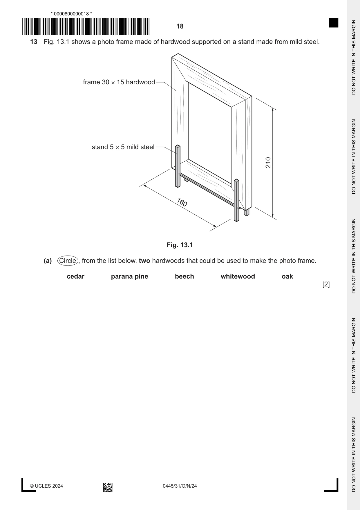
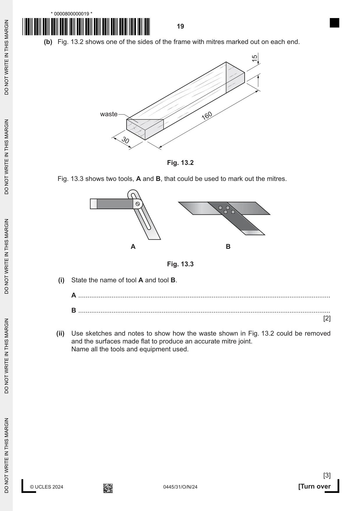
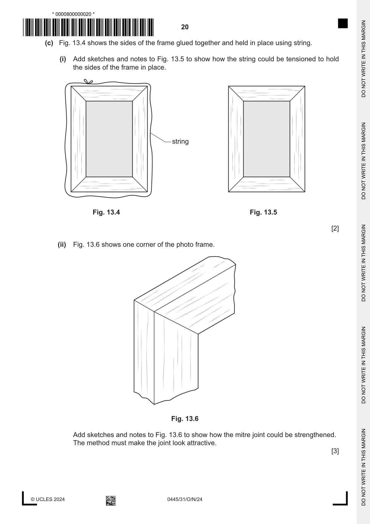
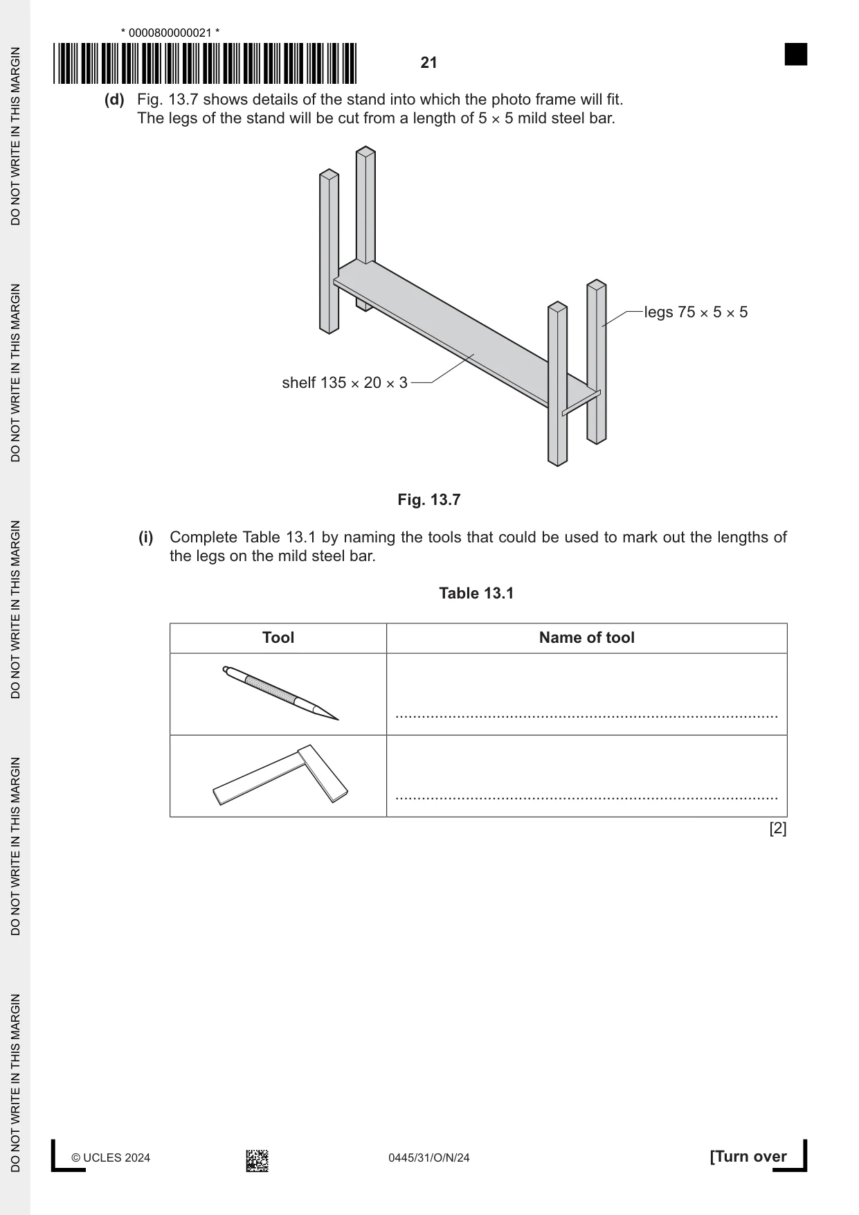
13 Fig. 13.1 shows a photo frame made of hardwood supported on a stand made from mild steel. frame 30 × 15 hardwood stand 5 × 5 mild steel 210 160 Fig. 13.1 (a) Circle , from the list below, two hardwoods that could be used to make the photo frame. cedar parana pine beech whitewood oak [2] (b) Fig. 13.2 shows one of the sides of the frame with mitres marked out on each end. 15 waste 160 30 Fig. 13.2 Fig. 13.3 shows two tools, A and B, that could be used to mark out the mitres. A B Fig. 13.3 (i) State the name of tool A and tool B. A ........................................................................................................................................ B ........................................................................................................................................ [2] (ii) Use sketches and notes to show how the waste shown in Fig. 13.2 could be removed and the surfaces made flat to produce an accurate mitre joint. Name all the tools and equipment used. [3] (c) Fig. 13.4 shows the sides of the frame glued together and held in place using string. (i) Add sketches and notes to Fig. 13.5 to show how the string could be tensioned to hold the sides of the frame in place. string Fig. 13.4 Fig. 13.5 [2] (ii) Fig. 13.6 shows one corner of the photo frame. Fig. 13.6 Add sketches and notes to Fig. 13.6 to show how the mitre joint could be strengthened. The method must make the joint look attractive. [3]
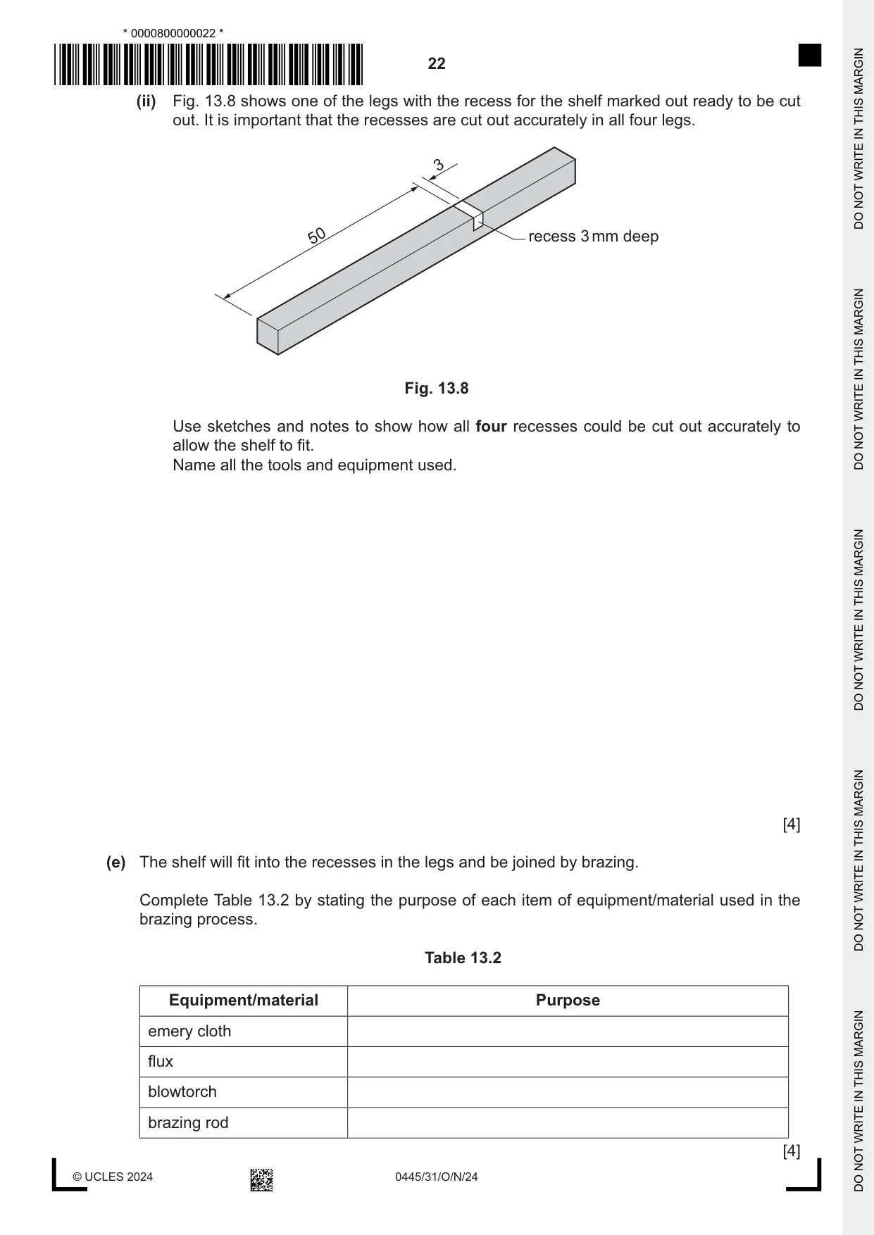
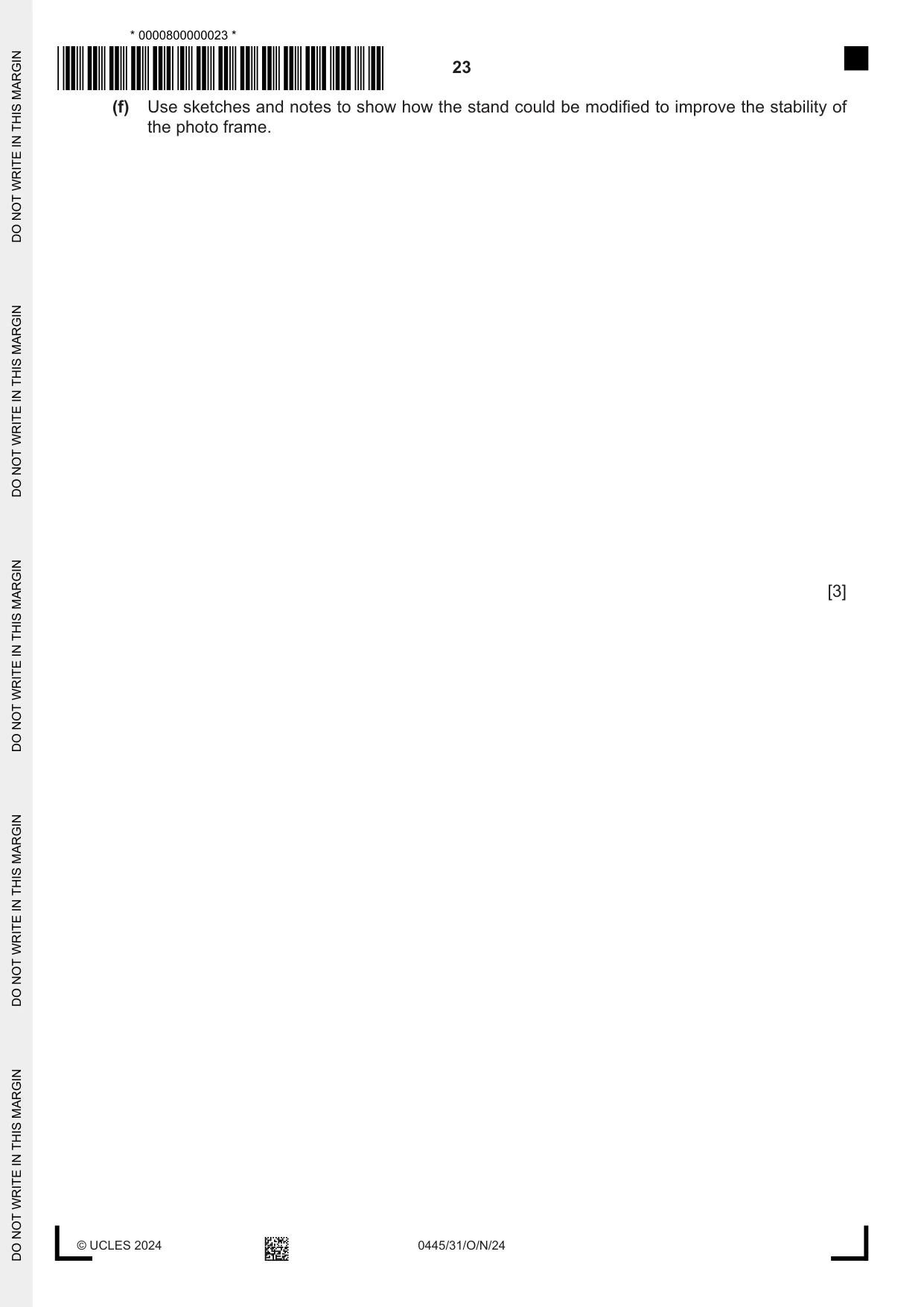
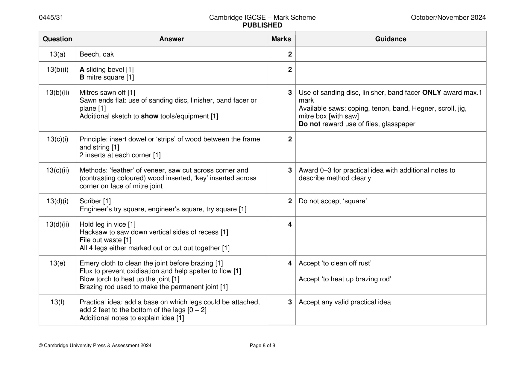
Mark scheme: 13(a) Beech, oak 2 13(b)(i) A sliding bevel [1] 2 B mitre square [1] 13(b)(ii) Mitres sawn off [1] 3 Use of sanding disc, linisher, band facer ONLY award max.1 Sawn ends flat: use of sanding disc, linisher, band facer or mark plane [1] Available saws: coping, tenon, band, Hegner, scroll, jig, Additional sketch to show tools/equipment [1] mitre box [with saw] Do not reward use of files, glasspaper 13(c)(i) Principle: insert dowel or ‘strips’ of wood between the frame 2 and string [1] 2 inserts at each corner [1] 13(c)(ii) Methods: ‘feather’ of veneer, saw cut across corner and 3 Award 0–3 for practical idea with additional notes to (contrasting coloured) wood inserted, ‘key’ inserted across describe method clearly corner on face of mitre joint 13(d)(i) Scriber [1] 2 Do not accept ‘square’ Engineer’s try square, engineer’s square, try square [1] 13(d)(ii) Hold leg in vice [1] 4 Hacksaw to saw down vertical sides of recess [1] File out waste [1] All 4 legs either marked out or cut out together [1] 13(e) Emery cloth to clean the joint before brazing [1] 4 Accept ‘to clean off rust’ Flux to prevent oxidisation and help spelter to flow [1] Blow torch to heat up the joint [1] Accept ‘to heat up brazing rod’ Brazing rod used to make the permanent joint [1] 13(f) Practical idea: add a base on which legs could be attached, 3 Accept any valid practical idea add 2 feet to the bottom of the legs [0 – 2] Additional notes to explain idea [1]
What was in this paper
The subtopics covered by these 13 questions, and how many questions each got. Open one in a new tab to see every Cambridge question on it.
What you needed in this session
Cambridge’s own grade thresholds for 2024 Oct/Nov, Paper 3 · Variant 1. A higher threshold means an easier paper — the bar moves with how the cohort did.