Cambridge IGCSE Design and Technology 0445 — 2023 Oct/Nov Paper 3 · Variant 3
0445/33/O/N/23 · 13 questions · 50 marks · ≈56 min
The question paper and its mark scheme, free to read here and free to download. This is Cambridge’s own paper, exactly as it was sat.
Question paper24 pages


Mark scheme9 pages
Answers below. Sit the paper first if you are practising.
Questions as text
Q1 · A student using a pillar drill
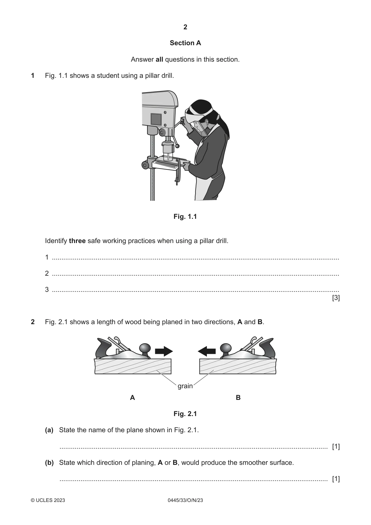
1 Fig. 1.1 shows a student using a pillar drill. Fig. 1.1 Identify three safe working practices when using a pillar drill. 1 ....................................................................................................................................................... 2 ....................................................................................................................................................... 3 ....................................................................................................................................................... [3]
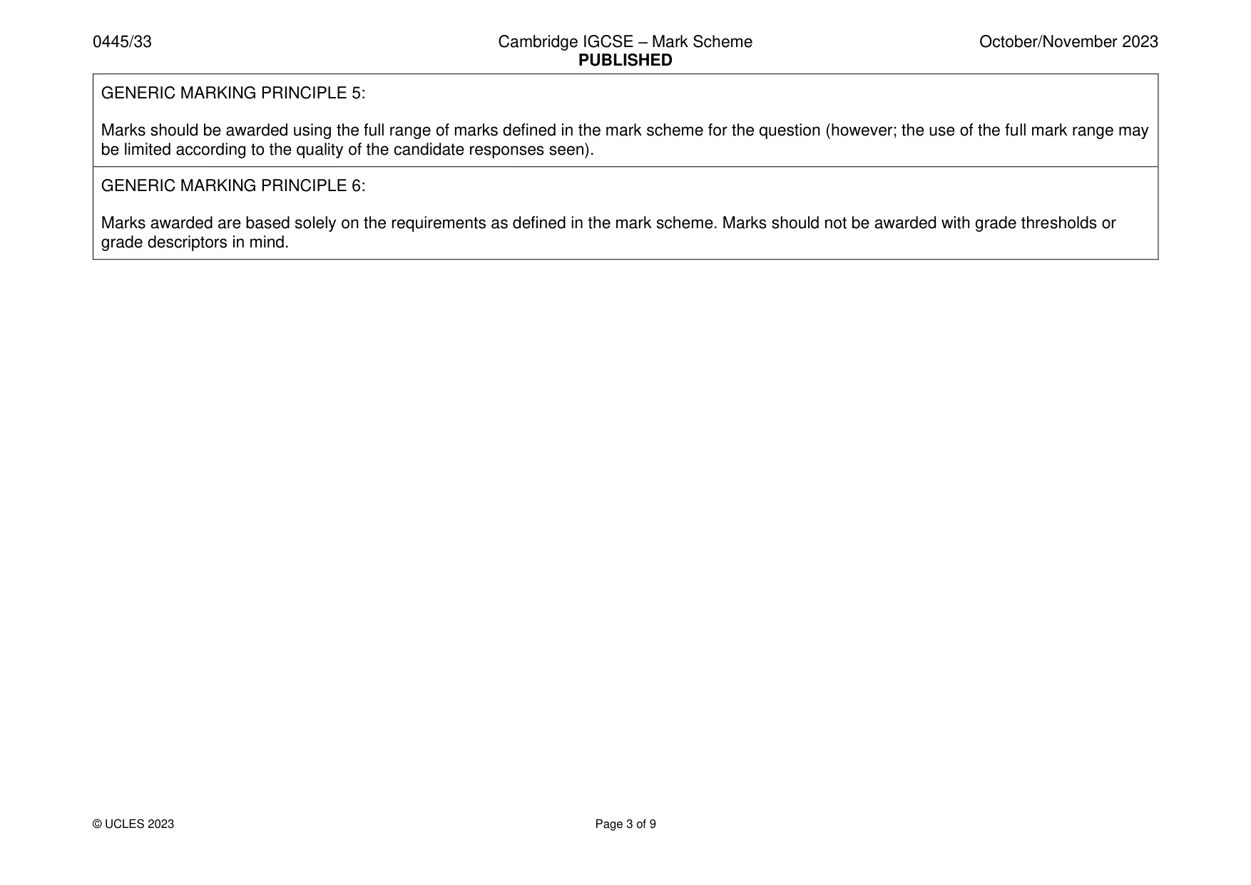
Mark scheme: Question Answer Marks Guidance 1 3 safe working practices: 3 Accept any valid safe working practices. • work secure Do not accept use of gloves, keep • guard in position fingers out of way of drill • face mask worn Do not accept sacrificial wood under • no loose clothing workpiece • hair tied back • wear apron • location of emergency STOP button • drill bit secure in chuck [3 1]
Q2 · A length of wood being planed in two directions, A and B
2 Fig. 2.1 shows a length of wood being planed in two directions, A and B. grain A B Fig. 2.1 (a) State the name of the plane shown in Fig. 2.1. ............................................................................................................................................. [1] (b) State which direction of planing, A or B, would produce the smoother surface. ............................................................................................................................................. [1]
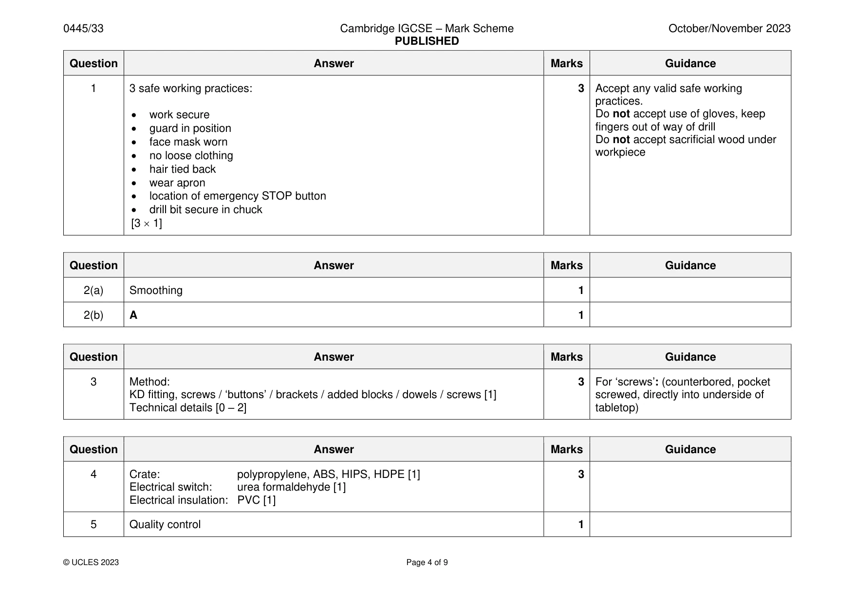
Mark scheme: 2(a) Smoothing 1 2(b) A 1
Q3 · Details of a tabletop that will be fastened to the rails of a small table
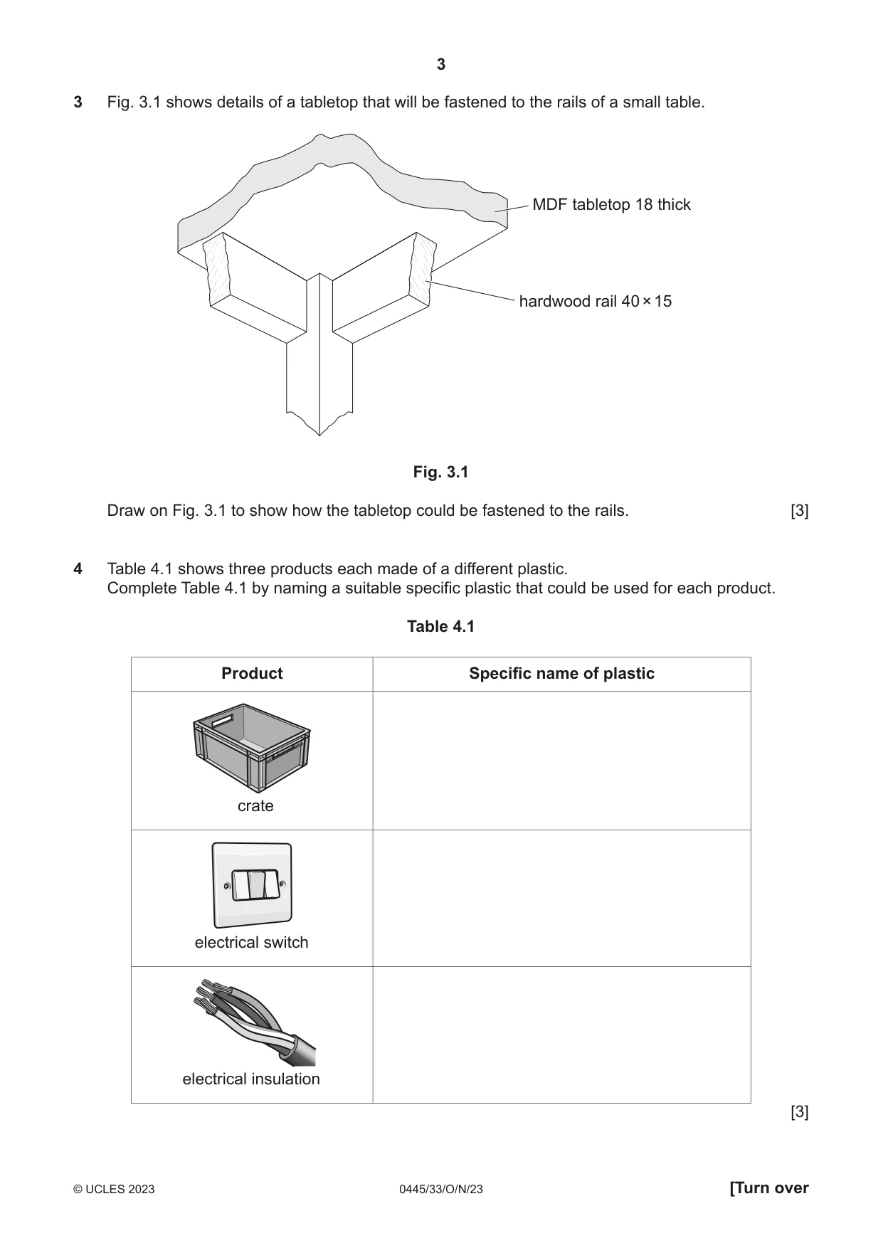
3 Fig. 3.1 shows details of a tabletop that will be fastened to the rails of a small table. MDF tabletop 18 thick hardwood rail 40 × 15 Fig. 3.1 Draw on Fig. 3.1 to show how the tabletop could be fastened to the rails. [3]
Mark scheme: 3 Method: 3 For ‘screws’: (counterbored, pocket KD fitting, screws / ‘buttons’ / brackets / added blocks / dowels / screws [1] screwed, directly into underside of Technical details [0 – 2] tabletop)
Q4 · Three products each made of a different plastic
4 Table 4.1 shows three products each made of a different plastic. Complete Table 4.1 by naming a suitable specific plastic that could be used for each product. Table 4.1 Product Specific name of plastic crate electrical switch electrical insulation [3]
Mark scheme: 4 Crate: polypropylene, ABS, HIPS, HDPE [1] 3 Electrical switch: urea formaldehyde [1] Electrical insulation: PVC [1]
Q5 · Complete the sentence below by selecting the correct term from the list
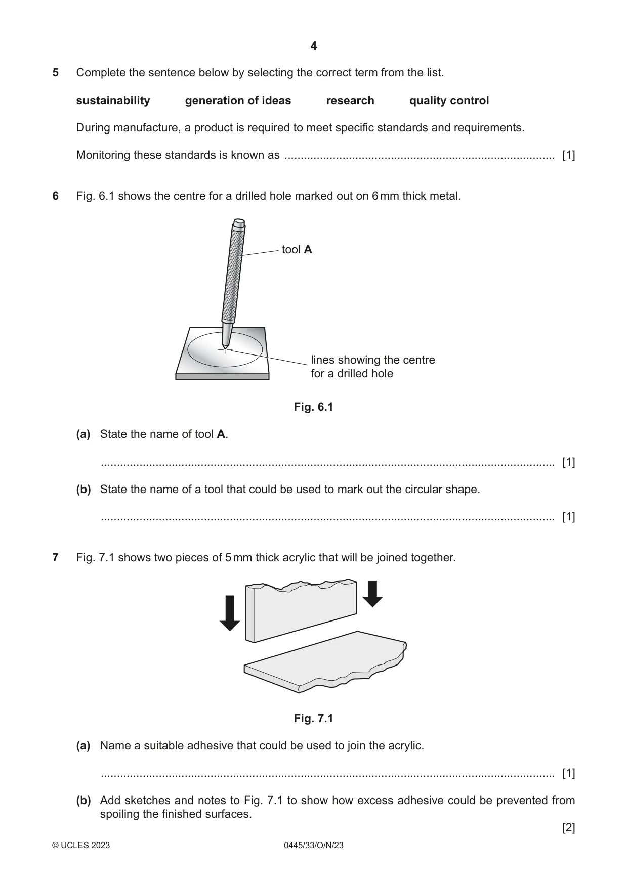
5 Complete the sentence below by selecting the correct term from the list. sustainability generation of ideas research quality control During manufacture, a product is required to meet specific standards and requirements. Monitoring these standards is known as .................................................................................... [1]
Mark scheme: 5 Quality control 1
Q6 · The centre for a drilled hole marked out on 6 mm thick metal
6 Fig. 6.1 shows the centre for a drilled hole marked out on 6 mm thick metal. tool A lines showing the centre for a drilled hole Fig. 6.1 (a) State the name of tool A. ............................................................................................................................................. [1] (b) State the name of a tool that could be used to mark out the circular shape. ............................................................................................................................................. [1]
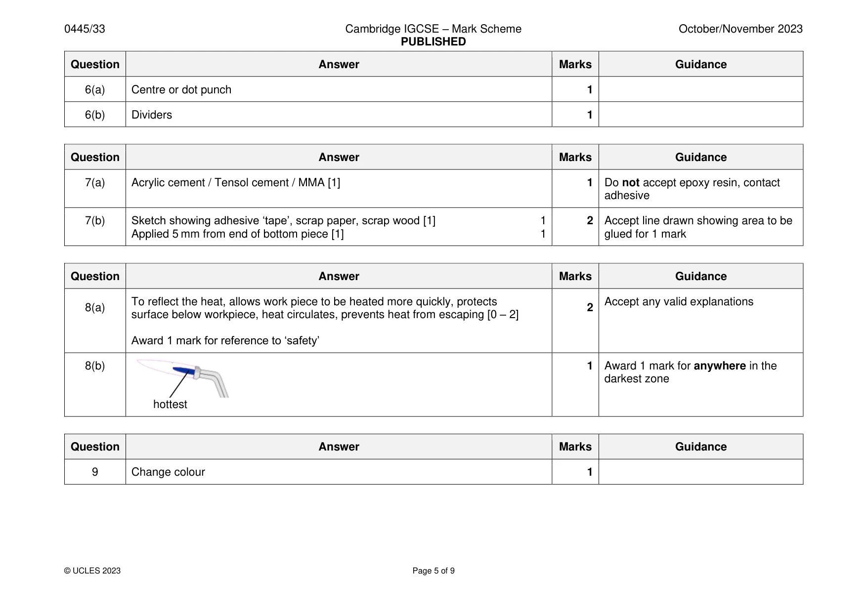
Mark scheme: 6(a) Centre or dot punch 1 6(b) Dividers 1
Q7 · Two pieces of 5 mm thick acrylic that will be joined together
7 Fig. 7.1 shows two pieces of 5 mm thick acrylic that will be joined together. Fig. 7.1 (a) Name a suitable adhesive that could be used to join the acrylic. ............................................................................................................................................. [1] (b) Add sketches and notes to Fig. 7.1 to show how excess adhesive could be prevented from spoiling the finished surfaces. [2]
Mark scheme: 7(a) Acrylic cement / Tensol cement / MMA [1] 1 Do not accept epoxy resin, contact adhesive 7(b) Sketch showing adhesive ‘tape’, scrap paper, scrap wood [1] 1 2 Accept line drawn showing area to be Applied 5 mm from end of bottom piece [1] 1 glued for 1 mark
Q8 · Two pieces of brass that will be soldered on a brazing hearth using a blow torch
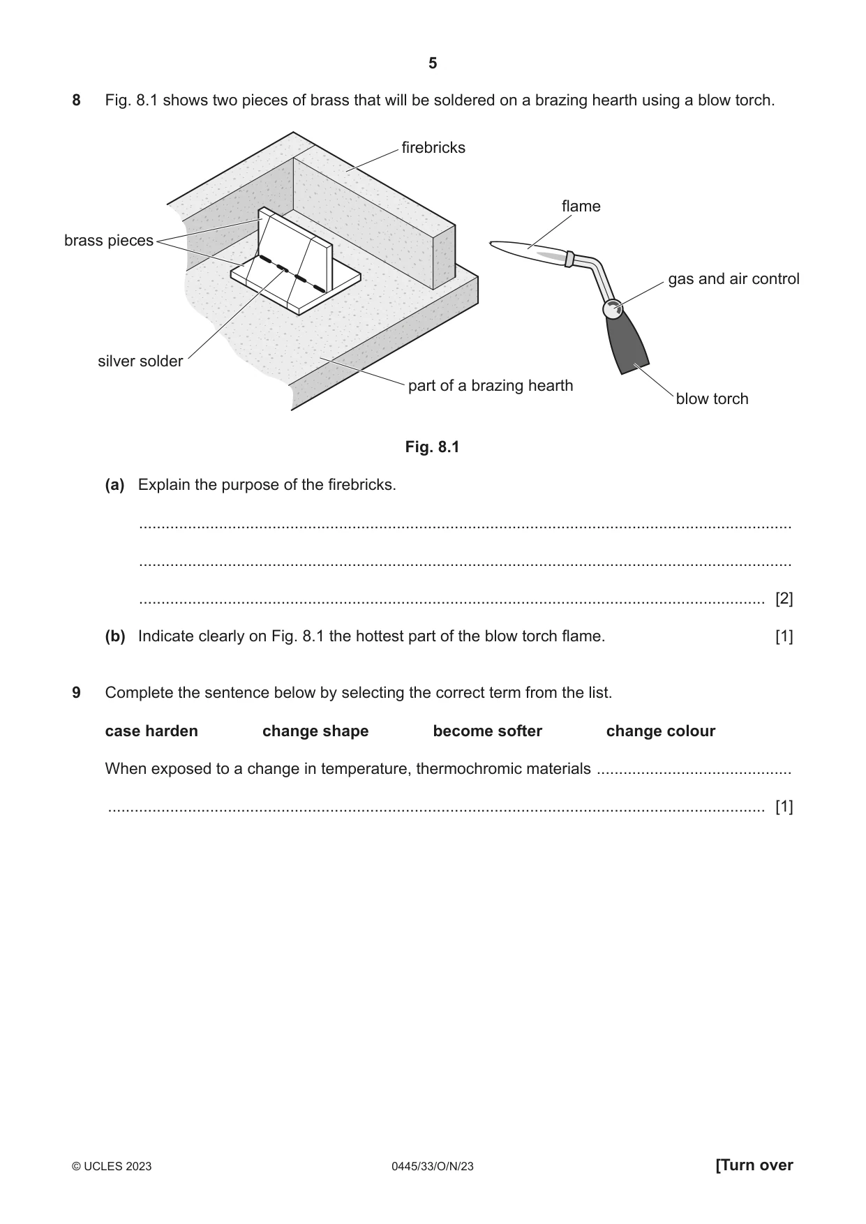
8 Fig. 8.1 shows two pieces of brass that will be soldered on a brazing hearth using a blow torch. firebricks flame brass pieces gas and air control silver solder part of a brazing hearth blow torch Fig. 8.1 (a) Explain the purpose of the firebricks. ................................................................................................................................................... ................................................................................................................................................... ............................................................................................................................................. [2] (b) Indicate clearly on Fig. 8.1 the hottest part of the blow torch flame. [1]
Mark scheme: 8(b) 1 Award 1 mark for anywhere in the darkest zone hottest
Q9 · Complete the sentence below by selecting the correct term from the list
9 Complete the sentence below by selecting the correct term from the list. case harden change shape become softer change colour When exposed to a change in temperature, thermochromic materials ............................................ .................................................................................................................................................... [1]
Mark scheme: 9 Change colour 1
Q10 · A basic design for a wall-mounted shelf made from 10 mm thick MDF
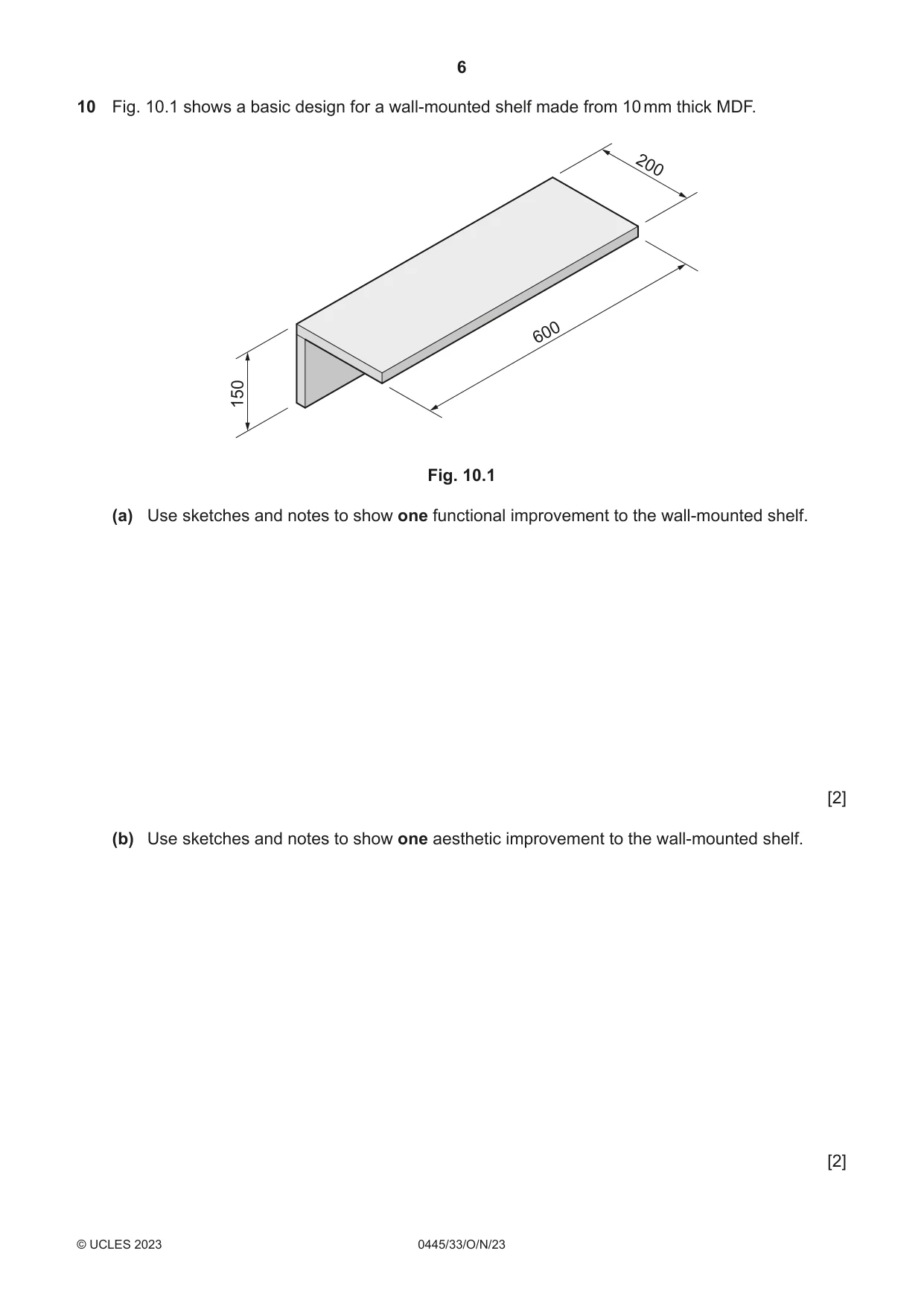
10 Fig. 10.1 shows a basic design for a wall-mounted shelf made from 10 mm thick MDF. 200 600 150 Fig. 10.1 (a) Use sketches and notes to show one functional improvement to the wall-mounted shelf. [2] (b) Use sketches and notes to show one aesthetic improvement to the wall-mounted shelf. [2]
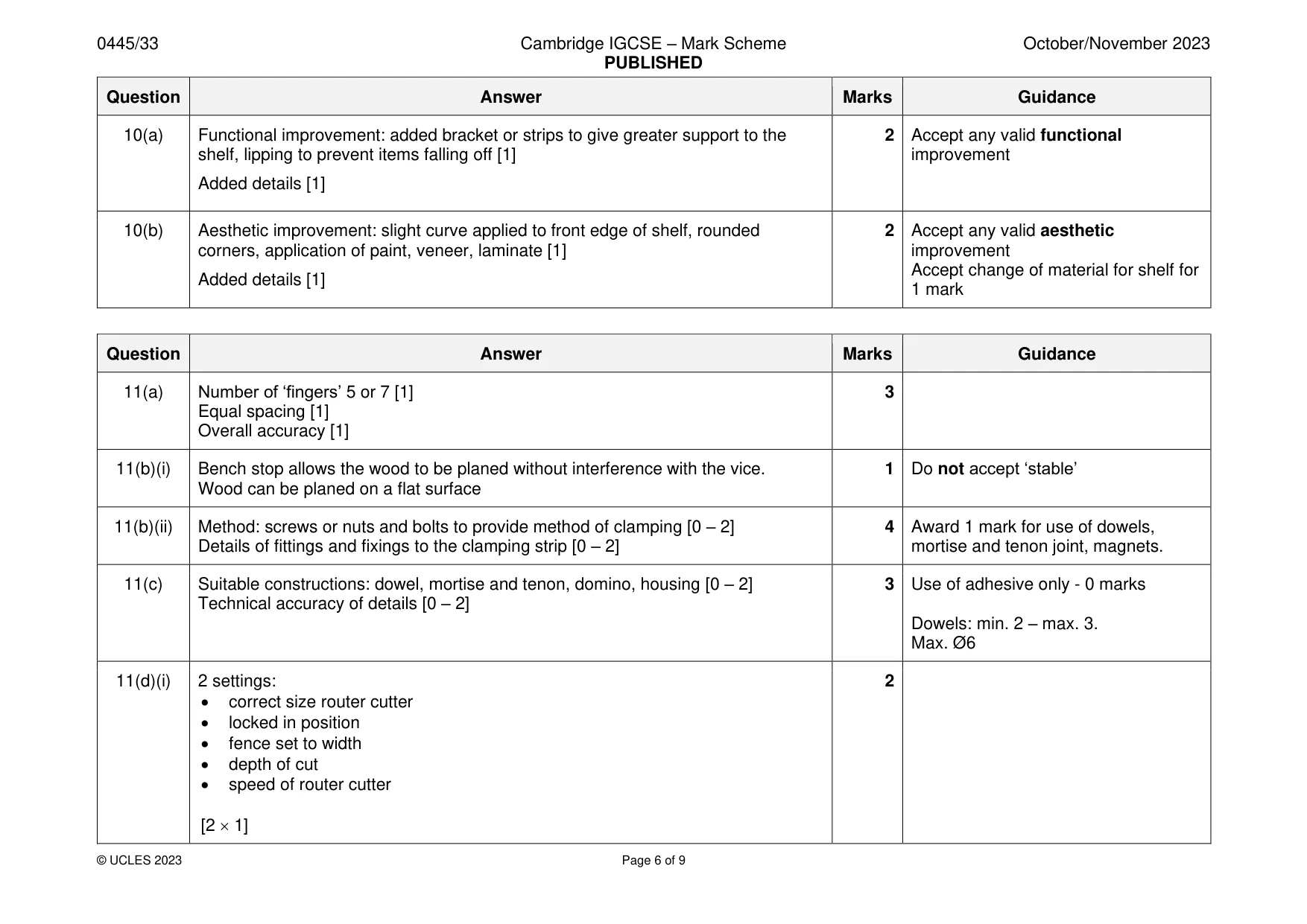
Mark scheme: 10(a) Functional improvement: added bracket or strips to give greater support to the 2 Accept any valid functional shelf, lipping to prevent items falling off [1] improvement Added details [1] 10(b) Aesthetic improvement: slight curve applied to front edge of shelf, rounded 2 Accept any valid aesthetic corners, application of paint, veneer, laminate [1] improvement Accept change of material for shelf for Added details [1] 1 mark
Q11 · Views of an incomplete design for a desktop box easel
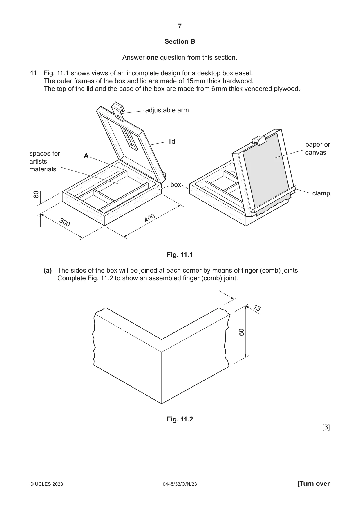
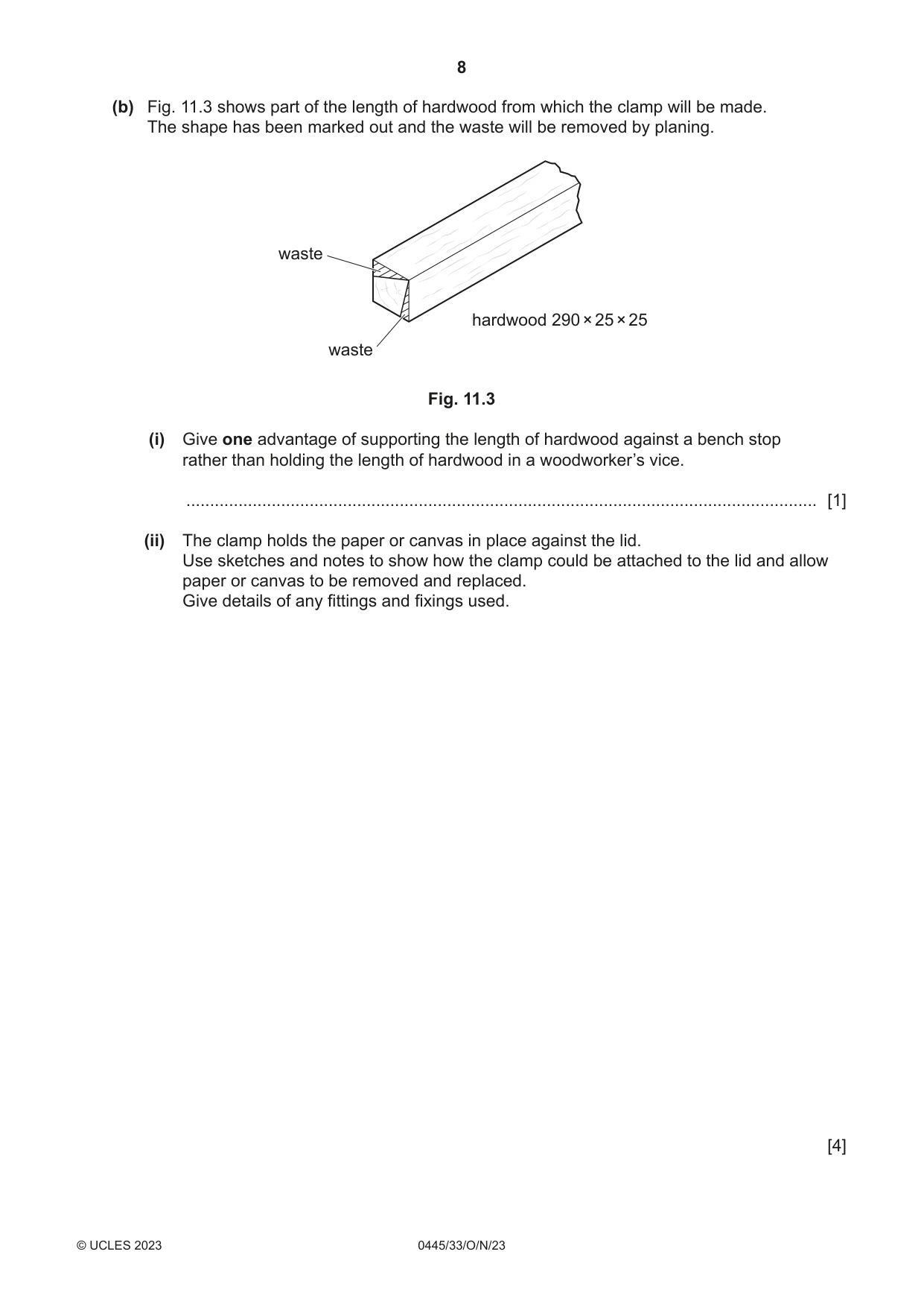
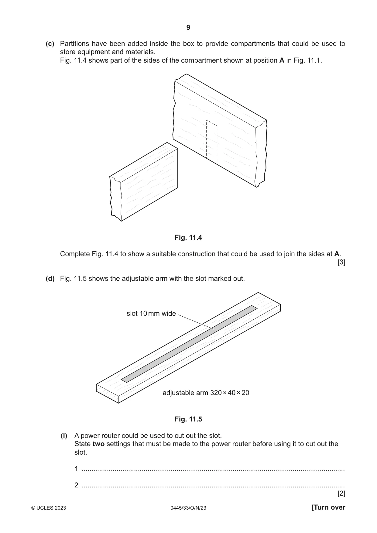
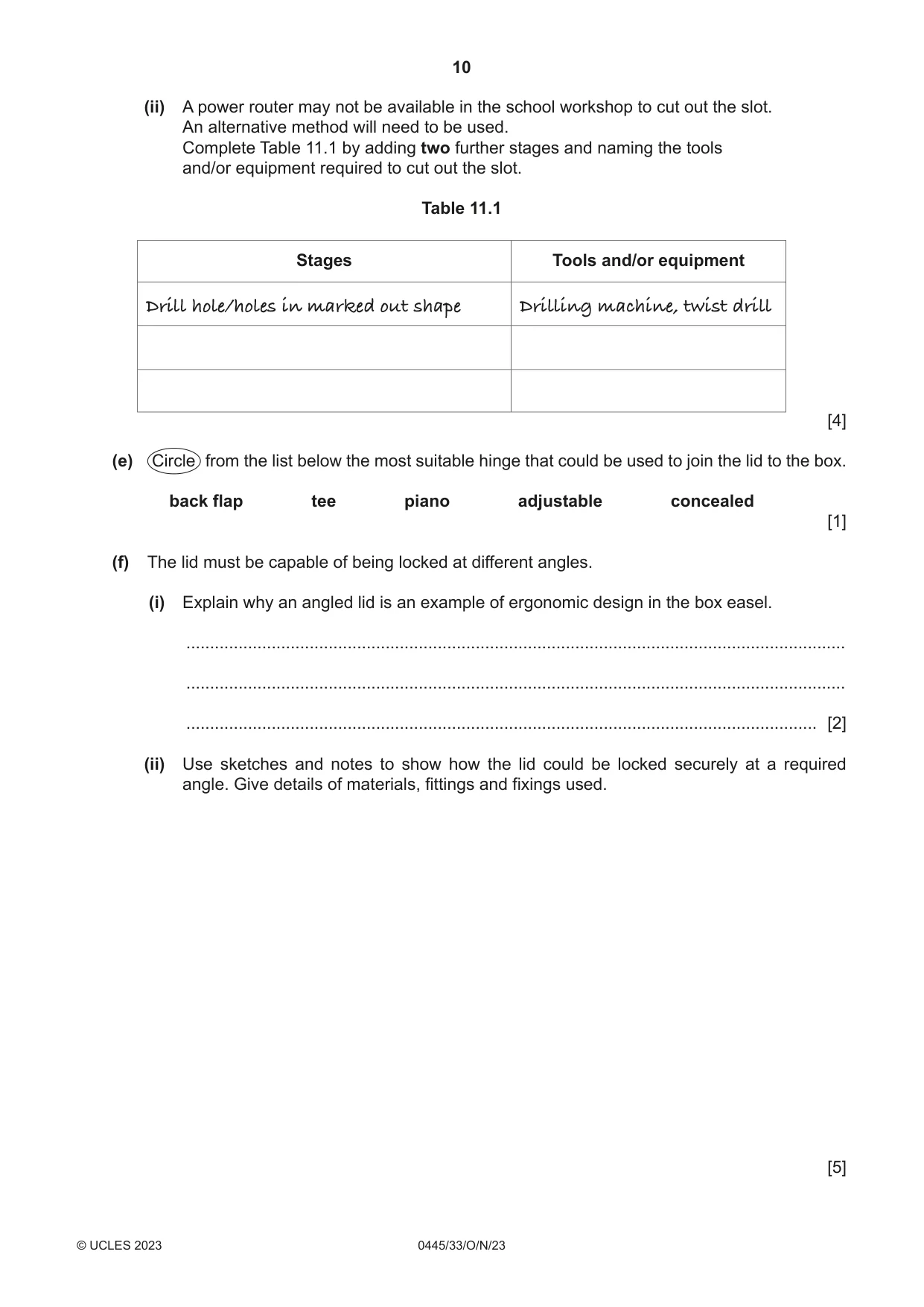
11 Fig. 11.1 shows views of an incomplete design for a desktop box easel. The outer frames of the box and lid are made of 15 mm thick hardwood. The top of the lid and the base of the box are made from 6 mm thick veneered plywood. adjustable arm lid paper or spaces for canvas A artists materials box 60 clamp 400 300 Fig. 11.1 (a) The sides of the box will be joined at each corner by means of finger (comb) joints. Complete Fig. 11.2 to show an assembled finger (comb) joint. 15 60 Fig. 11.2 [3] (b) Fig. 11.3 shows part of the length of hardwood from which the clamp will be made. The shape has been marked out and the waste will be removed by planing. waste hardwood 290 × 25 × 25 waste Fig. 11.3 (i) Give one advantage of supporting the length of hardwood against a bench stop rather than holding the length of hardwood in a woodworker’s vice. ..................................................................................................................................... [1] (ii) The clamp holds the paper or canvas in place against the lid. Use sketches and notes to show how the clamp could be attached to the lid and allow paper or canvas to be removed and replaced. Give details of any fittings and fixings used. [4] (c) Partitions have been added inside the box to provide compartments that could be used to store equipment and materials. Fig. 11.4 shows part of the sides of the compartment shown at position A in Fig. 11.1. Fig. 11.4 Complete Fig. 11.4 to show a suitable construction that could be used to join the sides at A. [3] (d) Fig. 11.5 shows the adjustable arm with the slot marked out. slot 10 mm wide adjustable arm 320 × 40 × 20 Fig. 11.5 (i) A power router could be used to cut out the slot. State two settings that must be made to the power router before using it to cut out the slot. 1 ........................................................................................................................................ 2 ........................................................................................................................................ [2] (ii) A power router may not be available in the school workshop to cut out the slot. An alternative method will need to be used. Complete Table 11.1 by adding two further stages and naming the tools and/or equipment required to cut out the slot. Table 11.1 Stages Tools and/or equipment Drill hole/holes in marked out shape Drilling machine, twist drill [4] (e) Circle from the list below the most suitable hinge that could be used to join the lid to the box. back flap tee piano adjustable concealed [1] (f) The lid must be capable of being locked at different angles. (i) Explain why an angled lid is an example of ergonomic design in the box easel. ........................................................................................................................................... ........................................................................................................................................... ..................................................................................................................................... [2] (ii) Use sketches and notes to show how the lid could be locked securely at a required angle. Give details of materials, fittings and fixings used. [5]
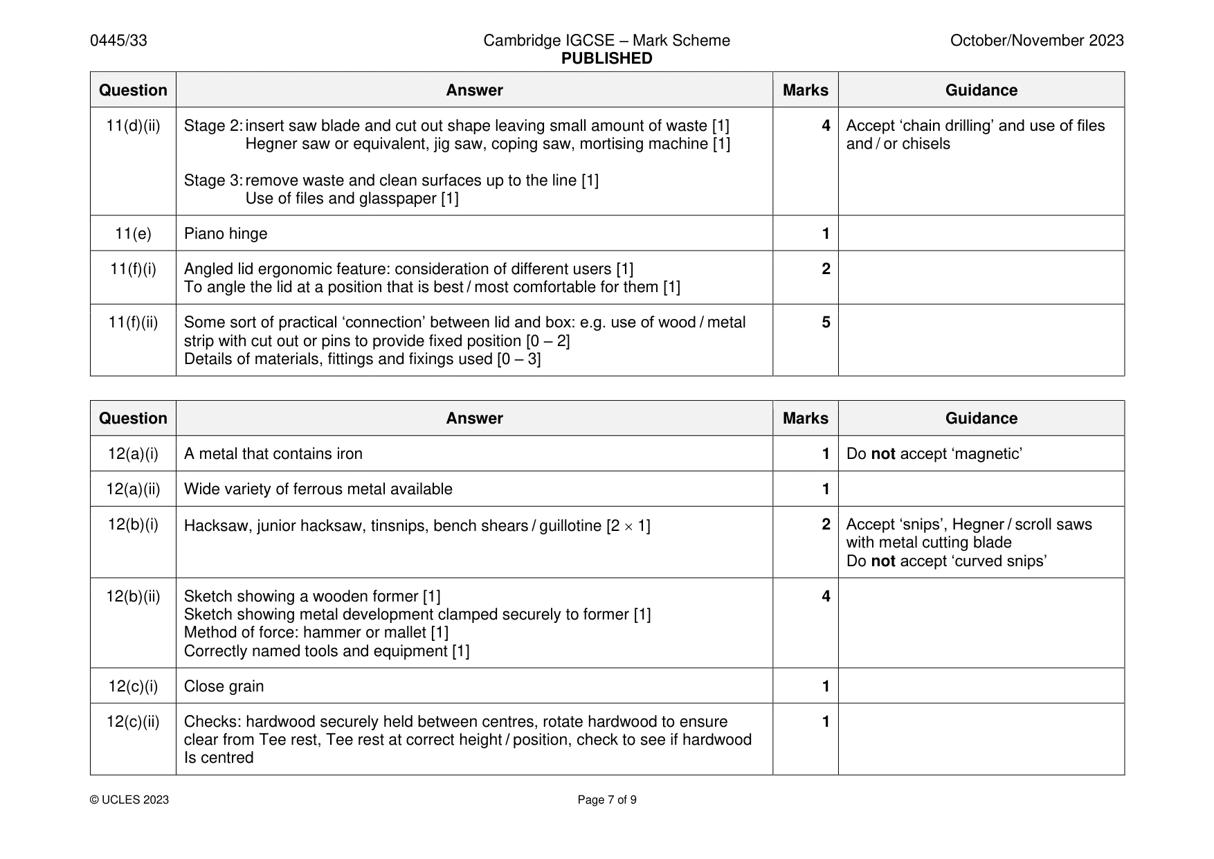
Mark scheme: 11(a) Number of ‘fingers’ 5 or 7 [1] 3 Equal spacing [1] Overall accuracy [1] 11(b)(i) Bench stop allows the wood to be planed without interference with the vice. 1 Do not accept ‘stable’ Wood can be planed on a flat surface 11(b)(ii) Method: screws or nuts and bolts to provide method of clamping [0 – 2] 4 Award 1 mark for use of dowels, Details of fittings and fixings to the clamping strip [0 – 2] mortise and tenon joint, magnets. 11(c) Suitable constructions: dowel, mortise and tenon, domino, housing [0 – 2] 3 Use of adhesive only - 0 marks Technical accuracy of details [0 – 2] Dowels: min. 2 – max. 3. Max. Ø6 11(d)(i) 2 settings: 2 • correct size router cutter • locked in position • fence set to width • depth of cut • speed of router cutter [2 1] 11(d)(ii) Stage 2: insert saw blade and cut out shape leaving small amount of waste [1] 4 Accept ‘chain drilling’ and use of files Hegner saw or equivalent, jig saw, coping saw, mortising machine [1] and / or chisels Stage 3: remove waste and clean surfaces up to the line [1] Use of files and glasspaper [1] 11(e) Piano hinge 1 11(f)(i) Angled lid ergonomic feature: consideration of different users [1] 2 To angle the lid at a position that is best / most comfortable for them [1] 11(f)(ii) Some sort of practical ‘connection’ between lid and box: e.g. use of wood / metal 5 strip with cut out or pins to provide fixed position [0 – 2] Details of materials, fittings and fixings used [0 – 3]
Q12 · An incomplete design for a tape dispenser made mainly from 1.6 mm thick mild steel sheet
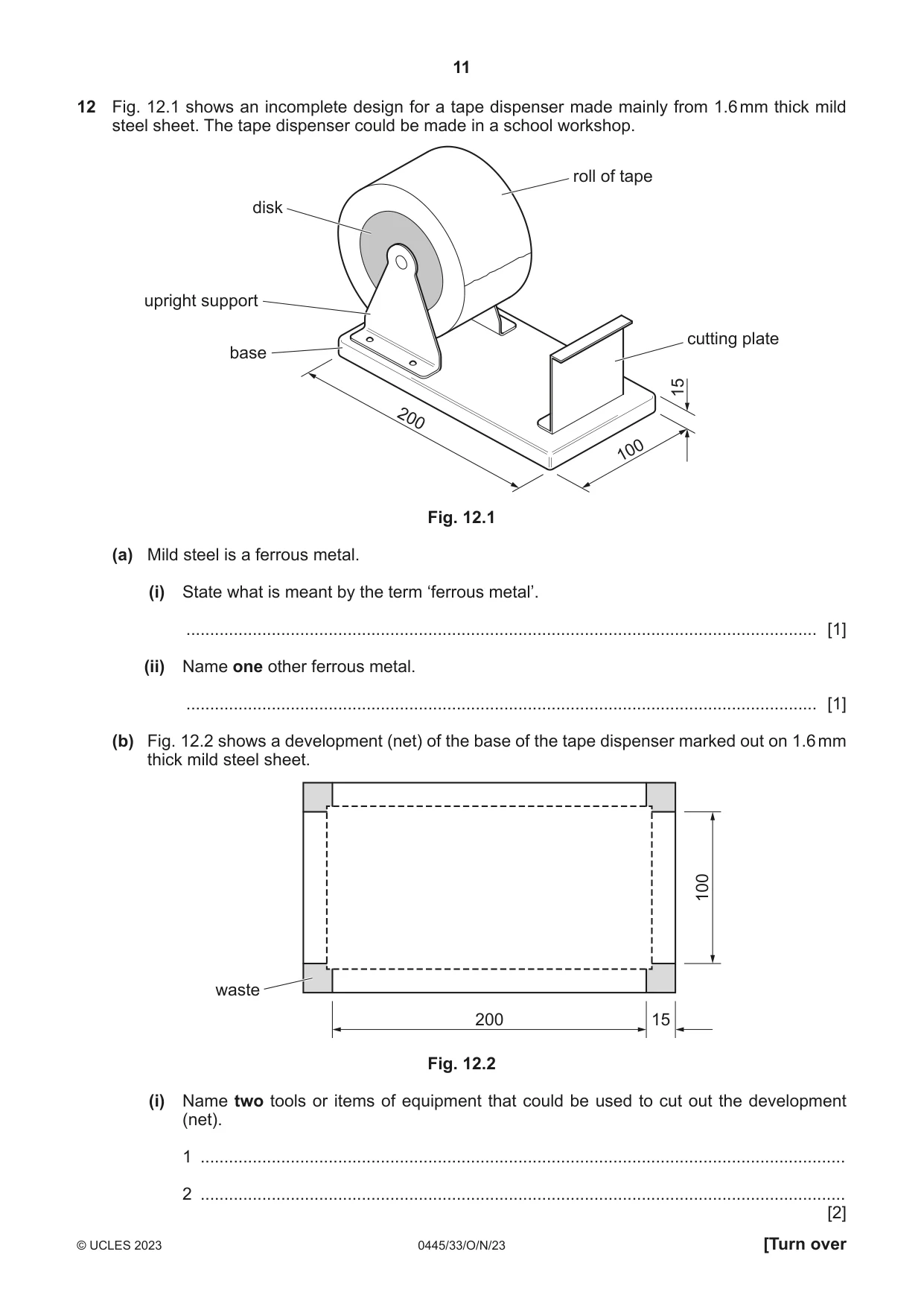
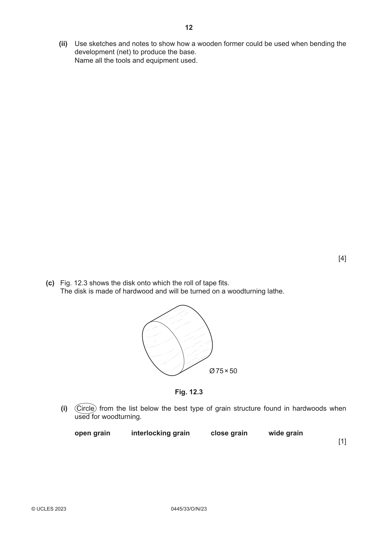
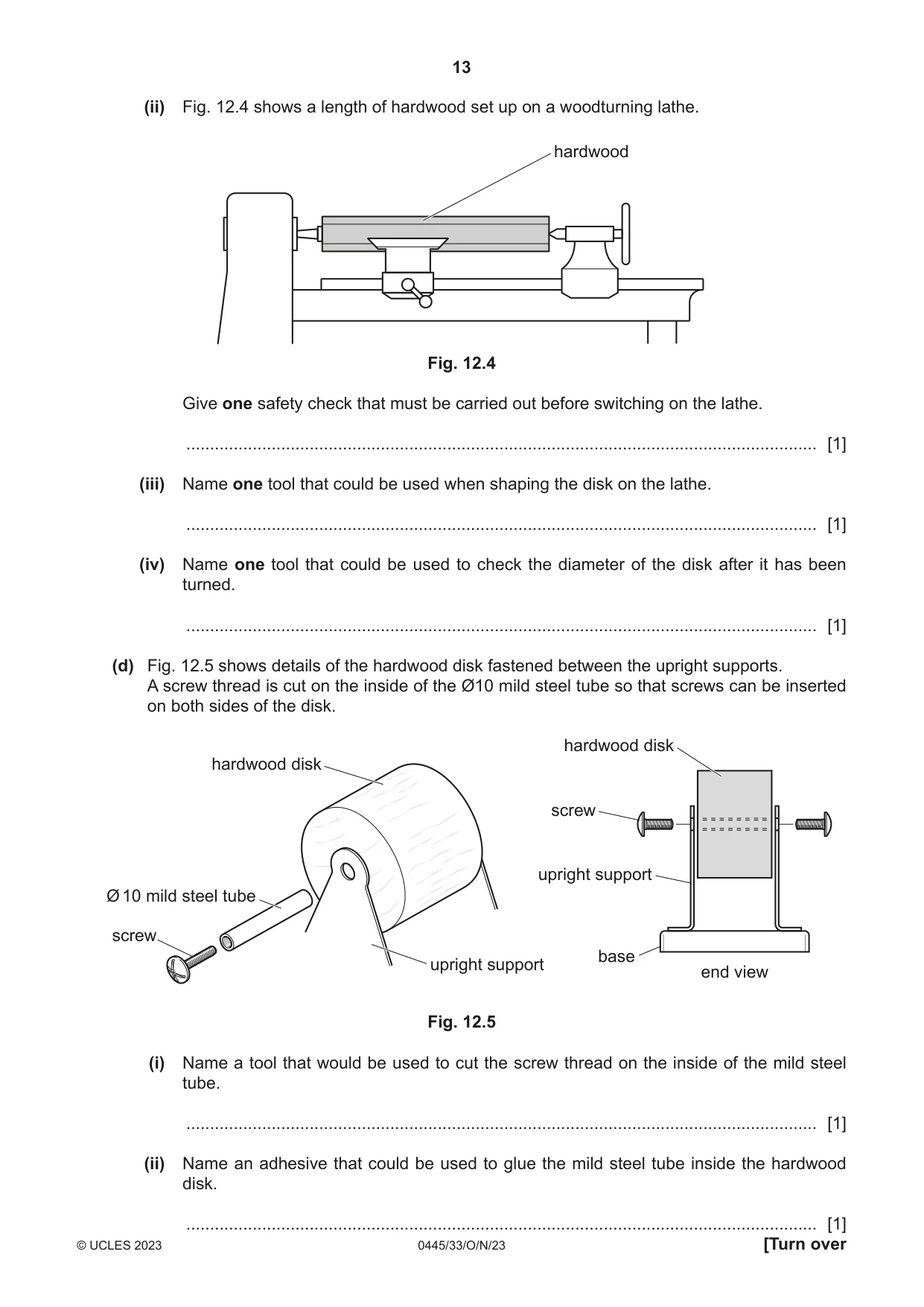
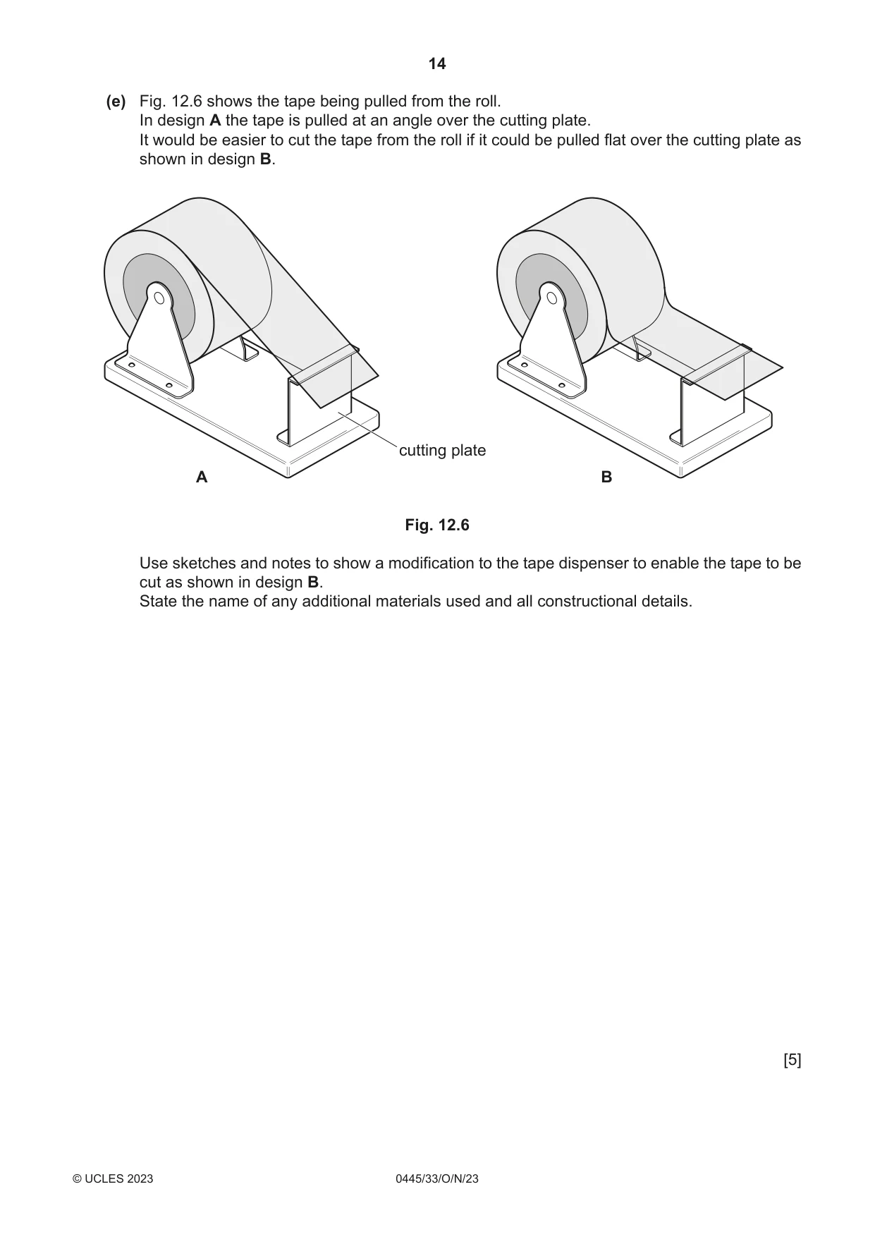
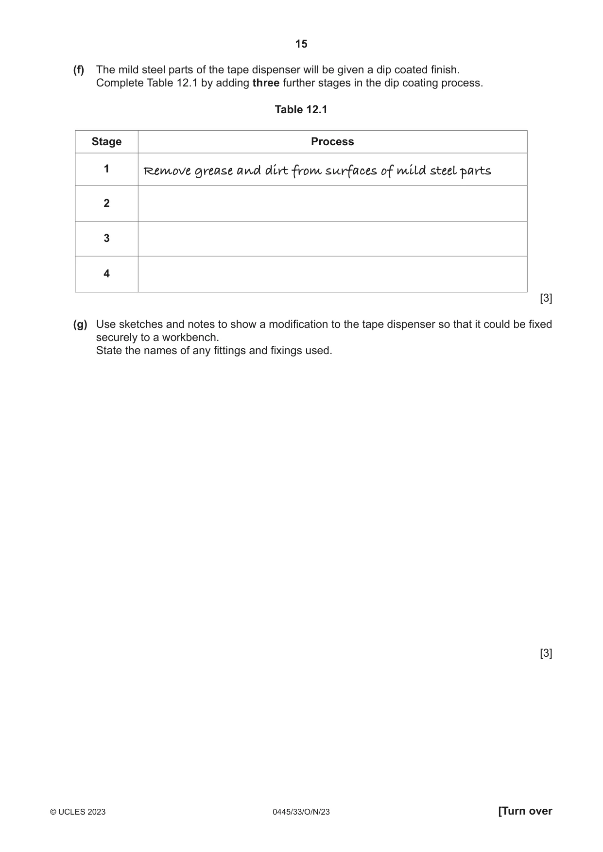
12 Fig. 12.1 shows an incomplete design for a tape dispenser made mainly from 1.6 mm thick mild steel sheet. The tape dispenser could be made in a school workshop. roll of tape disk upright support cutting plate base 15 200 100 Fig. 12.1 (a) Mild steel is a ferrous metal. (i) State what is meant by the term ‘ferrous metal’. ..................................................................................................................................... [1] (ii) Name one other ferrous metal. ..................................................................................................................................... [1] (b) Fig. 12.2 shows a development (net) of the base of the tape dispenser marked out on 1.6 mm thick mild steel sheet. 100 waste 200 15 Fig. 12.2 (i) Name two tools or items of equipment that could be used to cut out the development (net). 1 ........................................................................................................................................ 2 ........................................................................................................................................ [2] (ii) Use sketches and notes to show how a wooden former could be used when bending the development (net) to produce the base. Name all the tools and equipment used. [4] (c) Fig. 12.3 shows the disk onto which the roll of tape fits. The disk is made of hardwood and will be turned on a woodturning lathe. Ø 75 × 50 Fig. 12.3 (i) Circle from the list below the best type of grain structure found in hardwoods when used for woodturning. open grain interlocking grain close grain wide grain [1] (ii) Fig. 12.4 shows a length of hardwood set up on a woodturning lathe. hardwood Fig. 12.4 Give one safety check that must be carried out before switching on the lathe. ..................................................................................................................................... [1] (iii) Name one tool that could be used when shaping the disk on the lathe. ..................................................................................................................................... [1] (iv) Name one tool that could be used to check the diameter of the disk after it has been turned. ..................................................................................................................................... [1] (d) Fig. 12.5 shows details of the hardwood disk fastened between the upright supports. A screw thread is cut on the inside of the Ø10 mild steel tube so that screws can be inserted on both sides of the disk. hardwood disk hardwood disk screw upright support Ø 10 mild steel tube screw base upright support end view Fig. 12.5 (i) Name a tool that would be used to cut the screw thread on the inside of the mild steel tube. ..................................................................................................................................... [1] (ii) Name an adhesive that could be used to glue the mild steel tube inside the hardwood disk. (e) Fig. 12.6 shows the tape being pulled from the roll. In design A the tape is pulled at an angle over the cutting plate. It would be easier to cut the tape from the roll if it could be pulled flat over the cutting plate as shown in design B. cutting plate A B Fig. 12.6 Use sketches and notes to show a modification to the tape dispenser to enable the tape to be cut as shown in design B. State the name of any additional materials used and all constructional details. [5] (f) The mild steel parts of the tape dispenser will be given a dip coated finish. Complete Table 12.1 by adding three further stages in the dip coating process. Table 12.1 Stage Process 1 Remove grease and dirt from surfaces of mild steel parts 2 3 4 [3] (g) Use sketches and notes to show a modification to the tape dispenser so that it could be fixed securely to a workbench. State the names of any fittings and fixings used. [3]
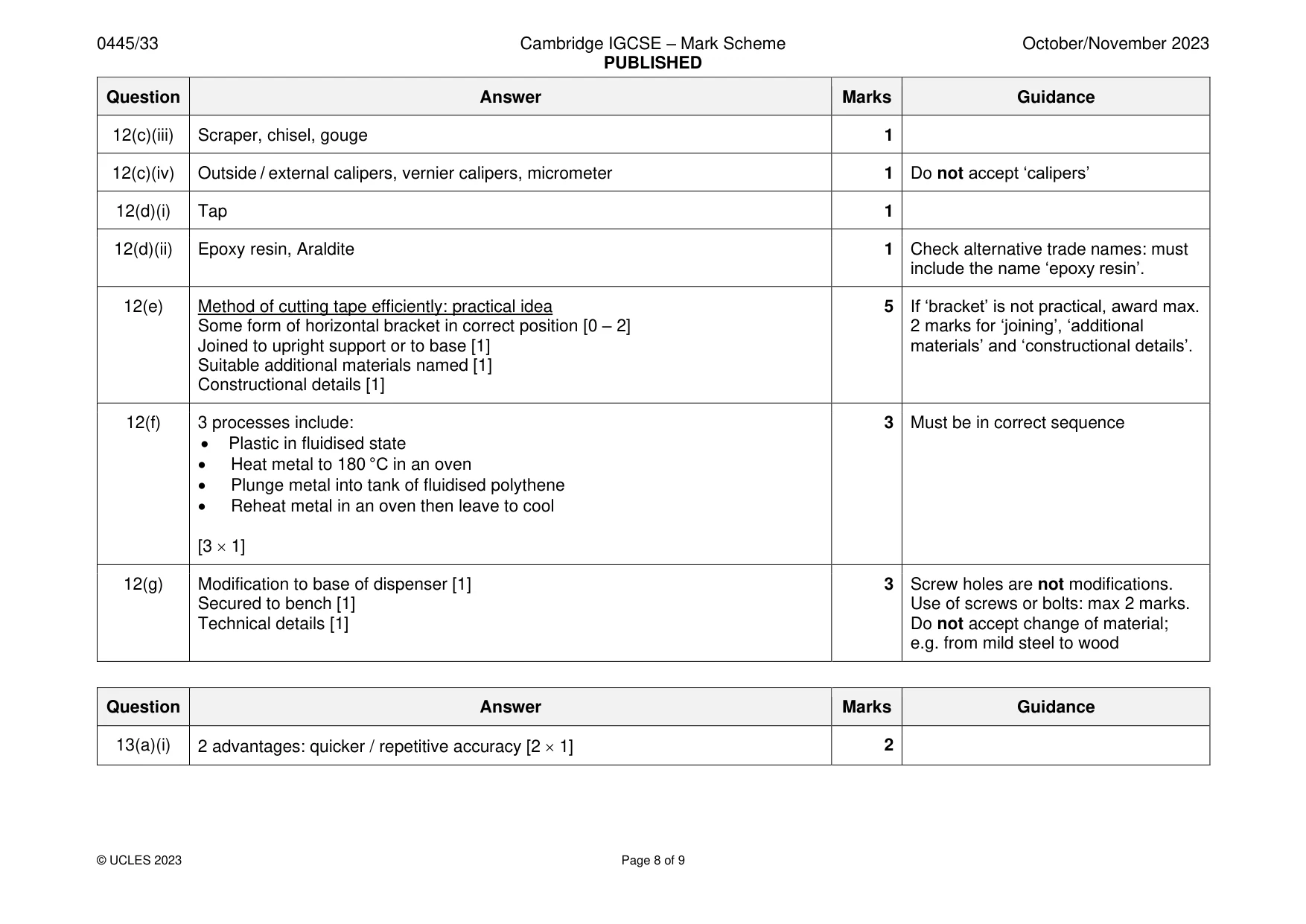
Mark scheme: 12(a)(i) A metal that contains iron 1 Do not accept ‘magnetic’ 12(a)(ii) Wide variety of ferrous metal available 1 12(b)(i) Hacksaw, junior hacksaw, tinsnips, bench shears / guillotine [2 1] 2 Accept ‘snips’, Hegner / scroll saws with metal cutting blade Do not accept ‘curved snips’ 12(b)(ii) Sketch showing a wooden former [1] 4 Sketch showing metal development clamped securely to former [1] Method of force: hammer or mallet [1] Correctly named tools and equipment [1] 12(c)(i) Close grain 1 12(c)(ii) Checks: hardwood securely held between centres, rotate hardwood to ensure 1 clear from Tee rest, Tee rest at correct height / position, check to see if hardwood Is centred 12(c)(iii) Scraper, chisel, gouge 1 12(c)(iv) Outside / external calipers, vernier calipers, micrometer 1 Do not accept ‘calipers’ 12(d)(i) Tap 1 12(d)(ii) Epoxy resin, Araldite 1 Check alternative trade names: must include the name ‘epoxy resin’. 12(e) Method of cutting tape efficiently: practical idea 5 If ‘bracket’ is not practical, award max. Some form of horizontal bracket in correct position [0 – 2] 2 marks for ‘joining’, ‘additional Joined to upright support or to base [1] materials’ and ‘constructional details’. Suitable additional materials named [1] Constructional details [1] 12(f) 3 processes include: 3 Must be in correct sequence • Plastic in fluidised state • Heat metal to 180 °C in an oven • Plunge metal into tank of fluidised polythene • Reheat metal in an oven then leave to cool [3 1] 12(g) Modification to base of dispenser [1] 3 Screw holes are not modifications. Secured to bench [1] Use of screws or bolts: max 2 marks. Technical details [1] Do not accept change of material; e.g. from mild steel to wood
Q13 · Views of a design for a novelty photograph holder made of 4 mm thick acrylic in the shape…
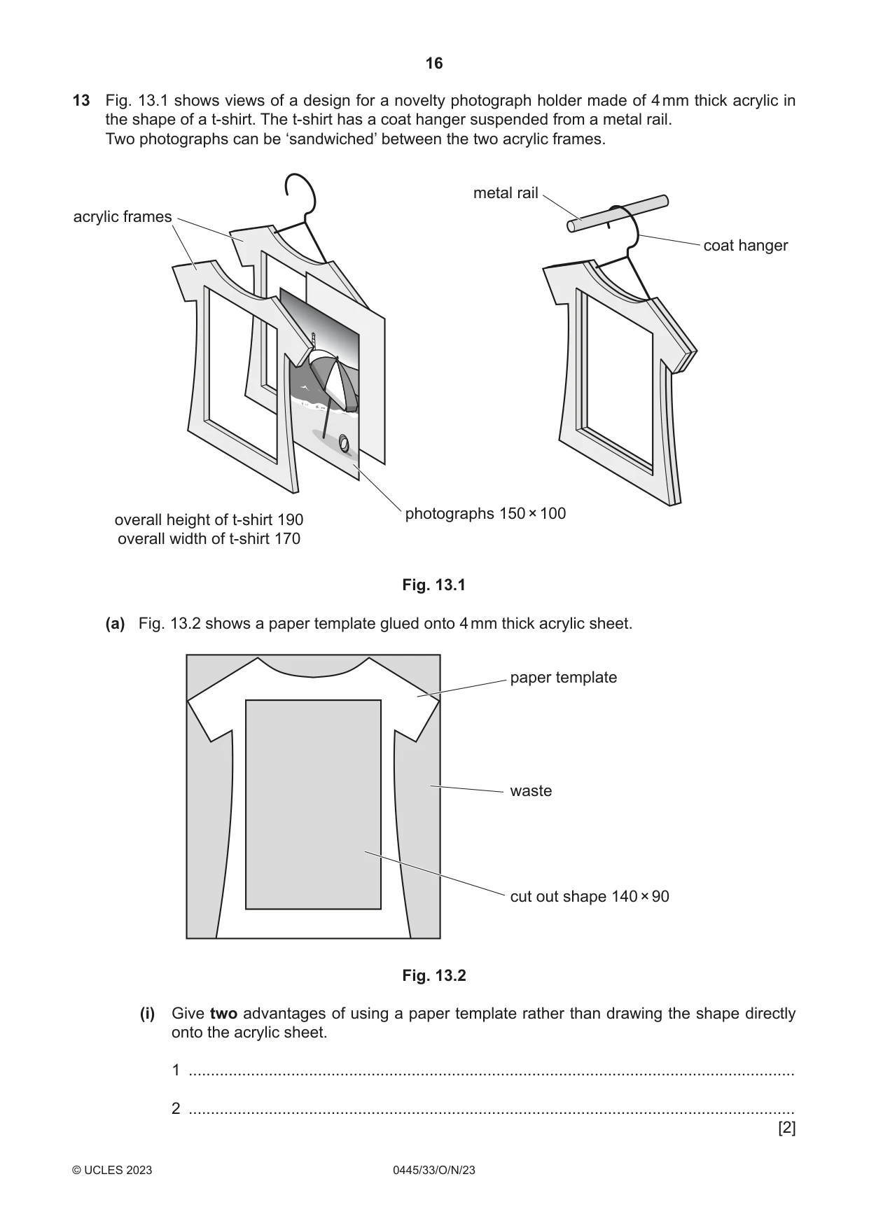
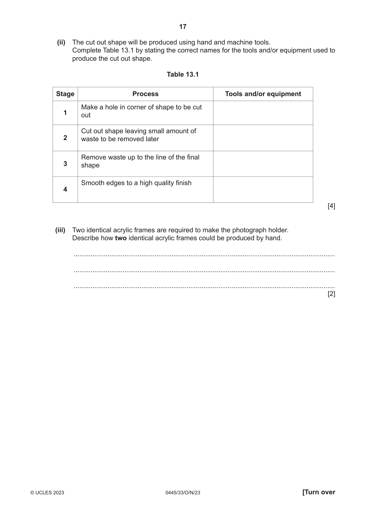
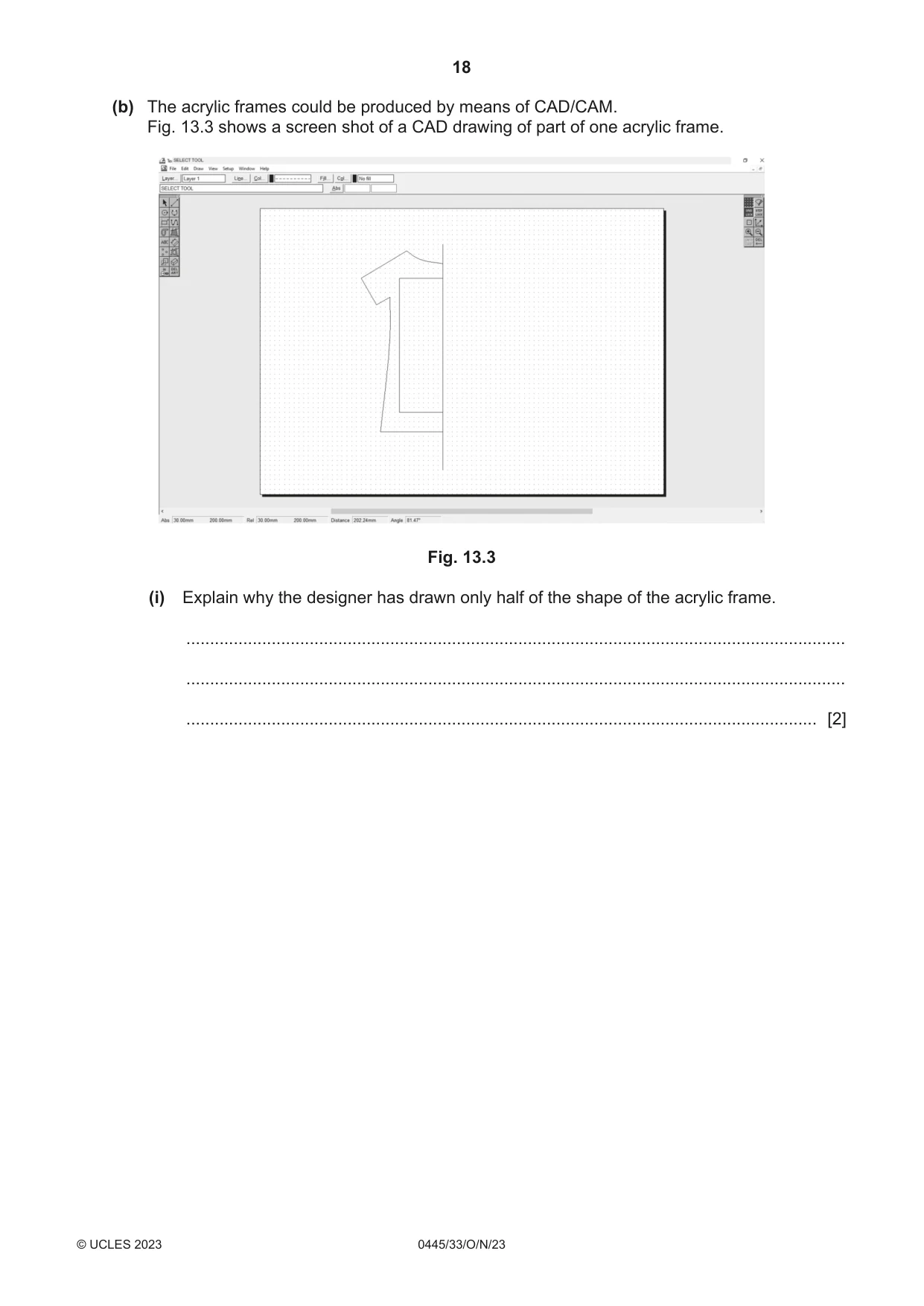
13 Fig. 13.1 shows views of a design for a novelty photograph holder made of 4 mm thick acrylic in the shape of a t-shirt. The t-shirt has a coat hanger suspended from a metal rail. Two photographs can be ‘sandwiched’ between the two acrylic frames. metal rail acrylic frames coat hanger photographs 150 × 100 overall height of t-shirt 190 overall width of t-shirt 170 Fig. 13.1 (a) Fig. 13.2 shows a paper template glued onto 4 mm thick acrylic sheet. paper template waste cut out shape 140 × 90 Fig. 13.2 (i) Give two advantages of using a paper template rather than drawing the shape directly onto the acrylic sheet. 1 ........................................................................................................................................ 2 ........................................................................................................................................ [2] (ii) The cut out shape will be produced using hand and machine tools. Complete Table 13.1 by stating the correct names for the tools and/or equipment used to produce the cut out shape. Table 13.1 Stage Process Tools and/or equipment Make a hole in corner of shape to be cut 1 out Cut out shape leaving small amount of 2 waste to be removed later Remove waste up to the line of the final 3 shape Smooth edges to a high quality finish 4 [4] (iii) Two identical acrylic frames are required to make the photograph holder. Describe how two identical acrylic frames could be produced by hand. ........................................................................................................................................... ........................................................................................................................................... ........................................................................................................................................... [2] (b) The acrylic frames could be produced by means of CAD/CAM. Fig. 13.3 shows a screen shot of a CAD drawing of part of one acrylic frame. Fig. 13.3 (i) Explain why the designer has drawn only half of the shape of the acrylic frame. ........................................................................................................................................... ........................................................................................................................................... ..................................................................................................................................... [2]
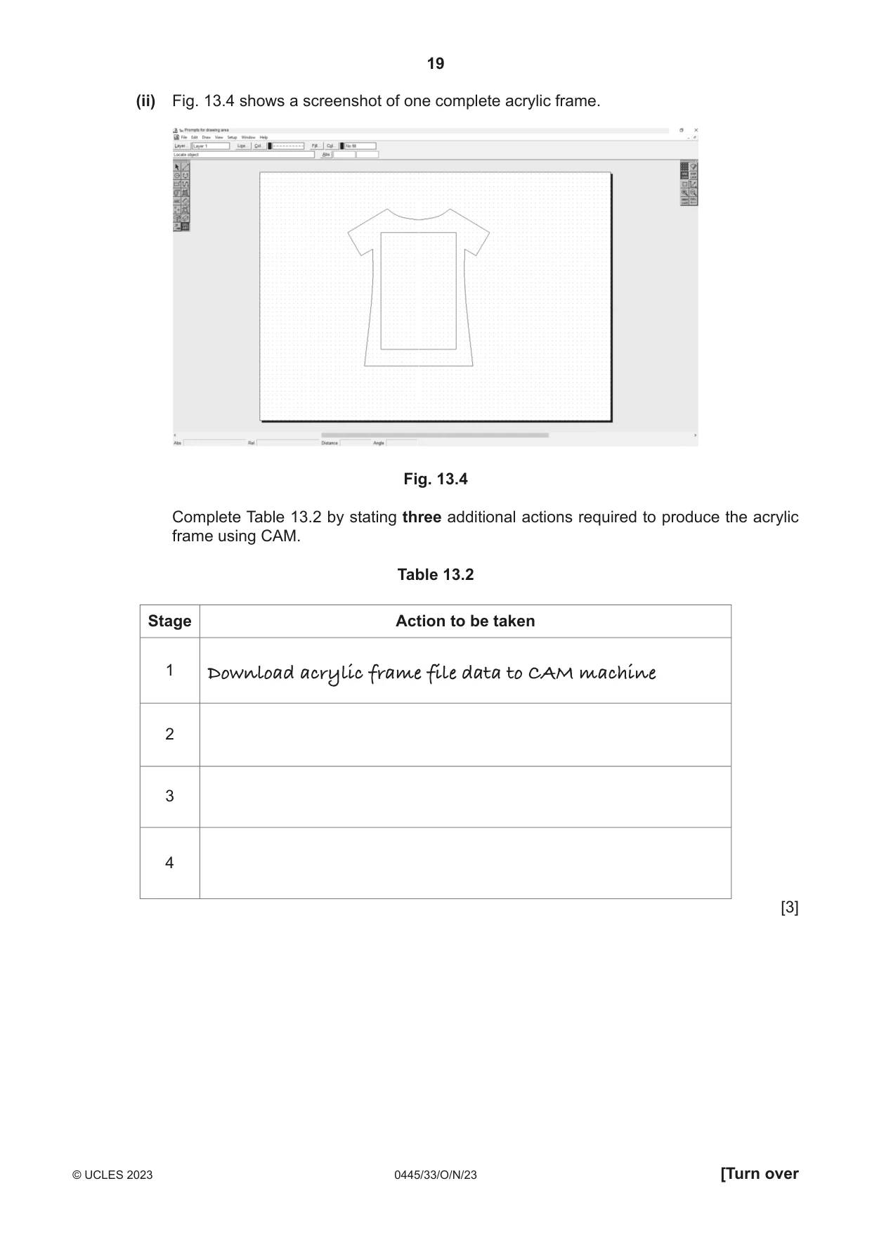
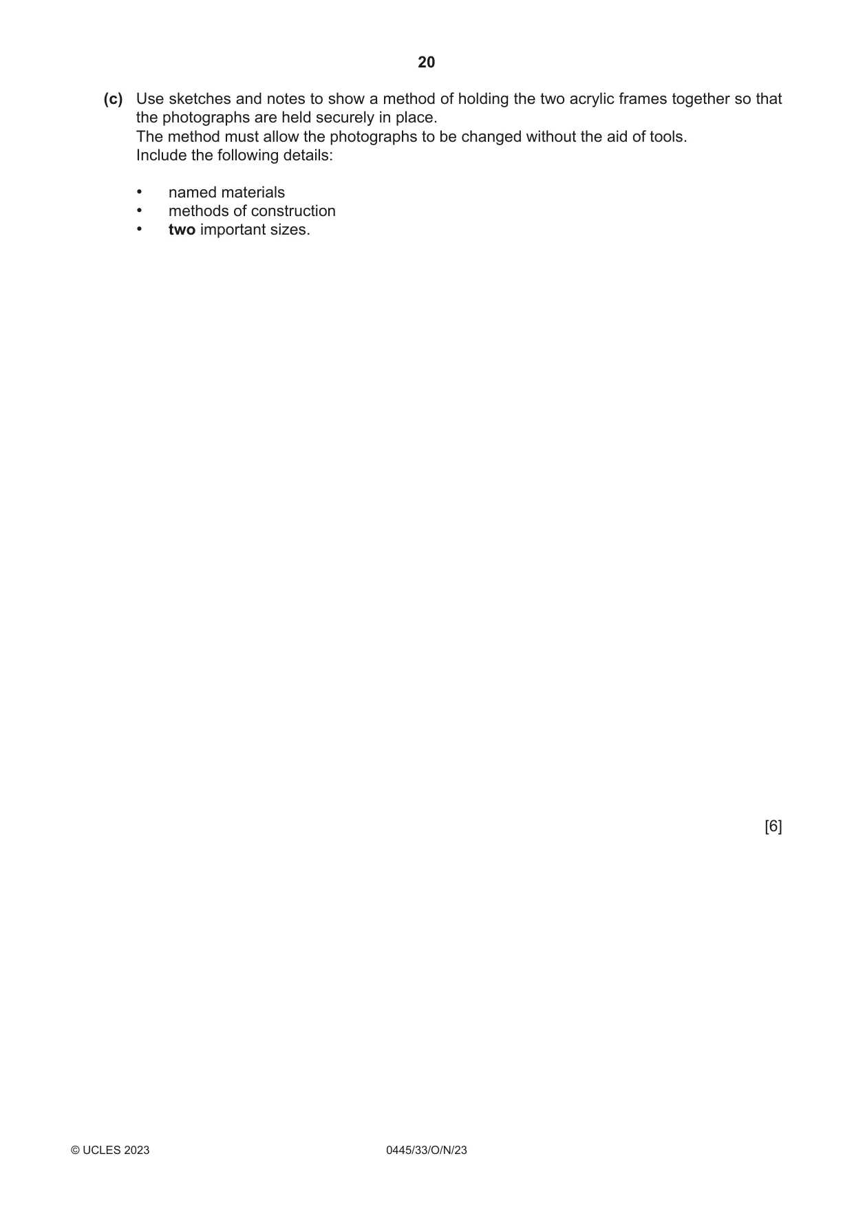
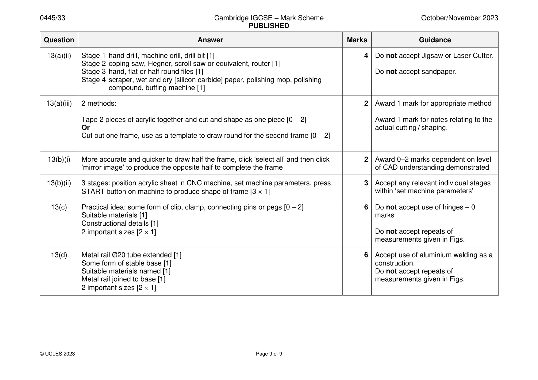
Mark scheme: 13(a)(i) 2 advantages: quicker / repetitive accuracy [2 1] 2 13(a)(ii) Stage 1 hand drill, machine drill, drill bit [1] 4 Do not accept Jigsaw or Laser Cutter. Stage 2 coping saw, Hegner, scroll saw or equivalent, router [1] Stage 3 hand, flat or half round files [1] Do not accept sandpaper. Stage 4 scraper, wet and dry [silicon carbide] paper, polishing mop, polishing compound, buffing machine [1] 13(a)(iii) 2 methods: 2 Award 1 mark for appropriate method Tape 2 pieces of acrylic together and cut and shape as one piece [0 – 2] Award 1 mark for notes relating to the Or actual cutting / shaping. Cut out one frame, use as a template to draw round for the second frame [0 – 2] 13(b)(i) More accurate and quicker to draw half the frame, click ‘select all’ and then click 2 Award 0–2 marks dependent on level ‘mirror image’ to produce the opposite half to complete the frame of CAD understanding demonstrated 13(b)(ii) 3 stages: position acrylic sheet in CNC machine, set machine parameters, press 3 Accept any relevant individual stages START button on machine to produce shape of frame [3 1] within ‘set machine parameters’ 13(c) Practical idea: some form of clip, clamp, connecting pins or pegs [0 – 2] 6 Do not accept use of hinges – 0 Suitable materials [1] marks Constructional details [1] 2 important sizes [2 1] Do not accept repeats of measurements given in Figs. 13(d) Metal rail Ø20 tube extended [1] 6 Accept use of aluminium welding as a Some form of stable base [1] construction. Suitable materials named [1] Do not accept repeats of Metal rail joined to base [1] measurements given in Figs. 2 important sizes [2 1]
What was in this paper
The subtopics covered by these 13 questions, and how many questions each got. Open one in a new tab to see every Cambridge question on it.
What you needed in this session
Cambridge’s own grade thresholds for 2023 Oct/Nov, Paper 3 · Variant 3. A higher threshold means an easier paper — the bar moves with how the cohort did.