Cambridge IGCSE Design and Technology 0445 — 2022 Oct/Nov Paper 3 · Variant 2
0445/32/O/N/22 · 13 questions · 50 marks · ≈56 min
The question paper and its mark scheme, free to read here and free to download. This is Cambridge’s own paper, exactly as it was sat.
Question paper20 pages
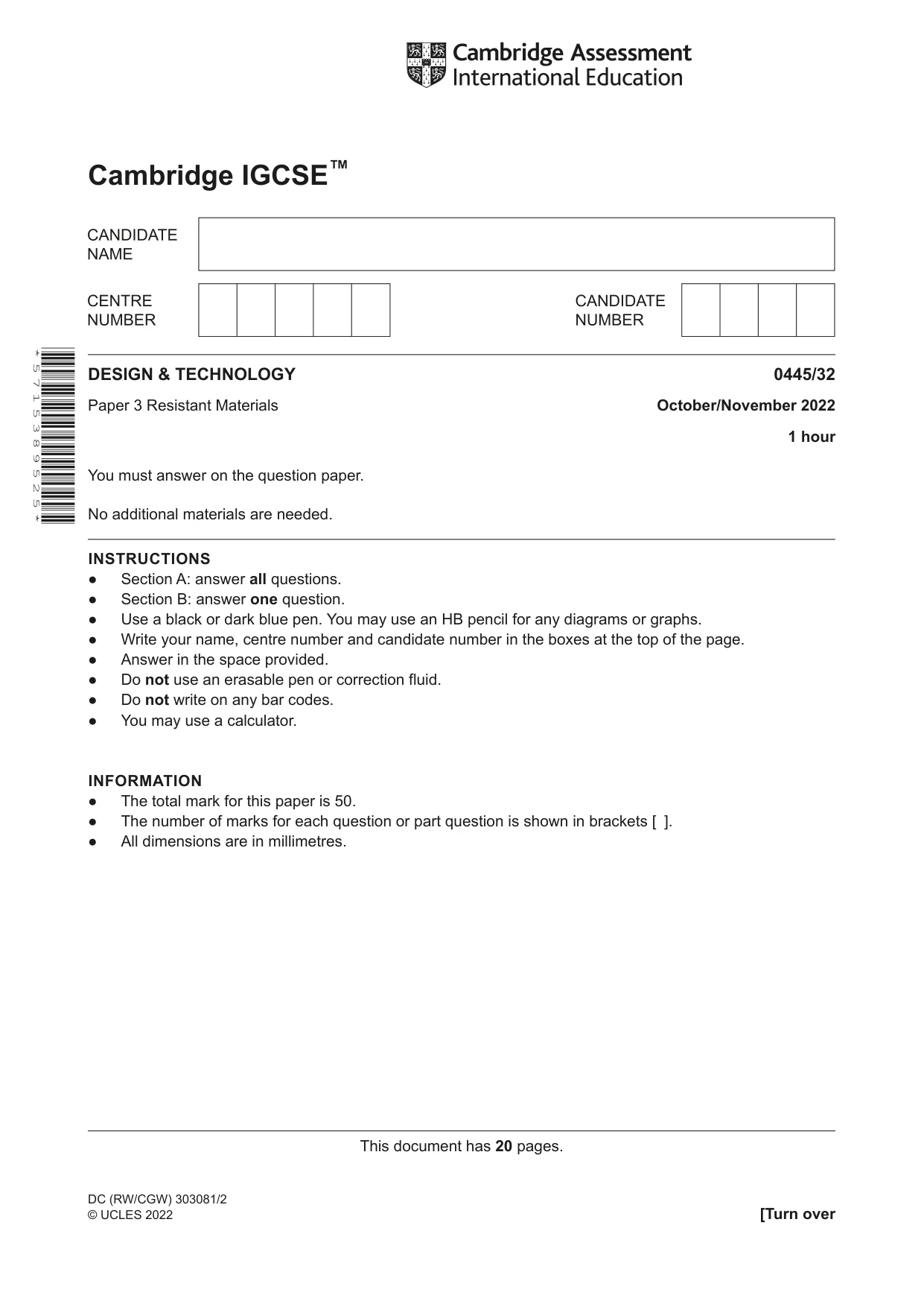
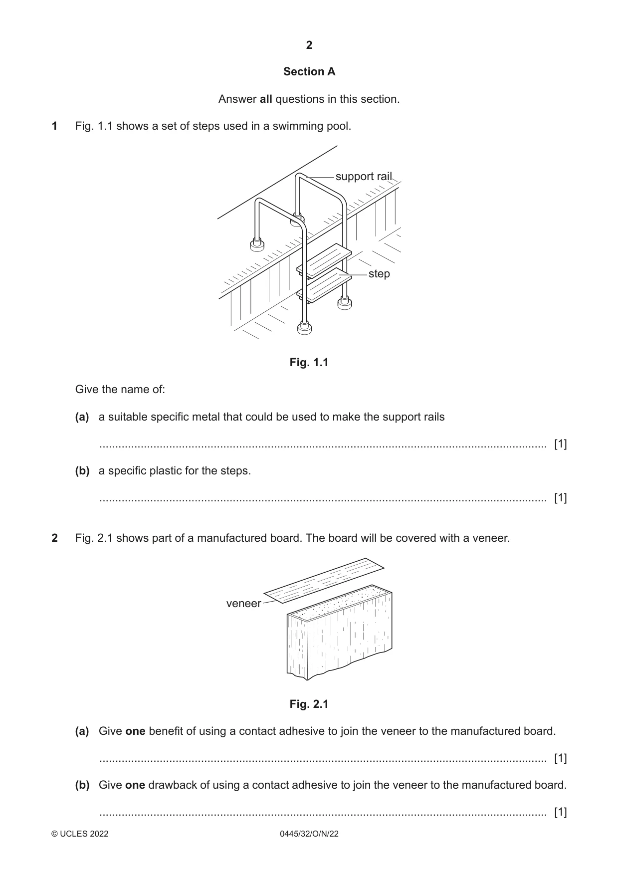
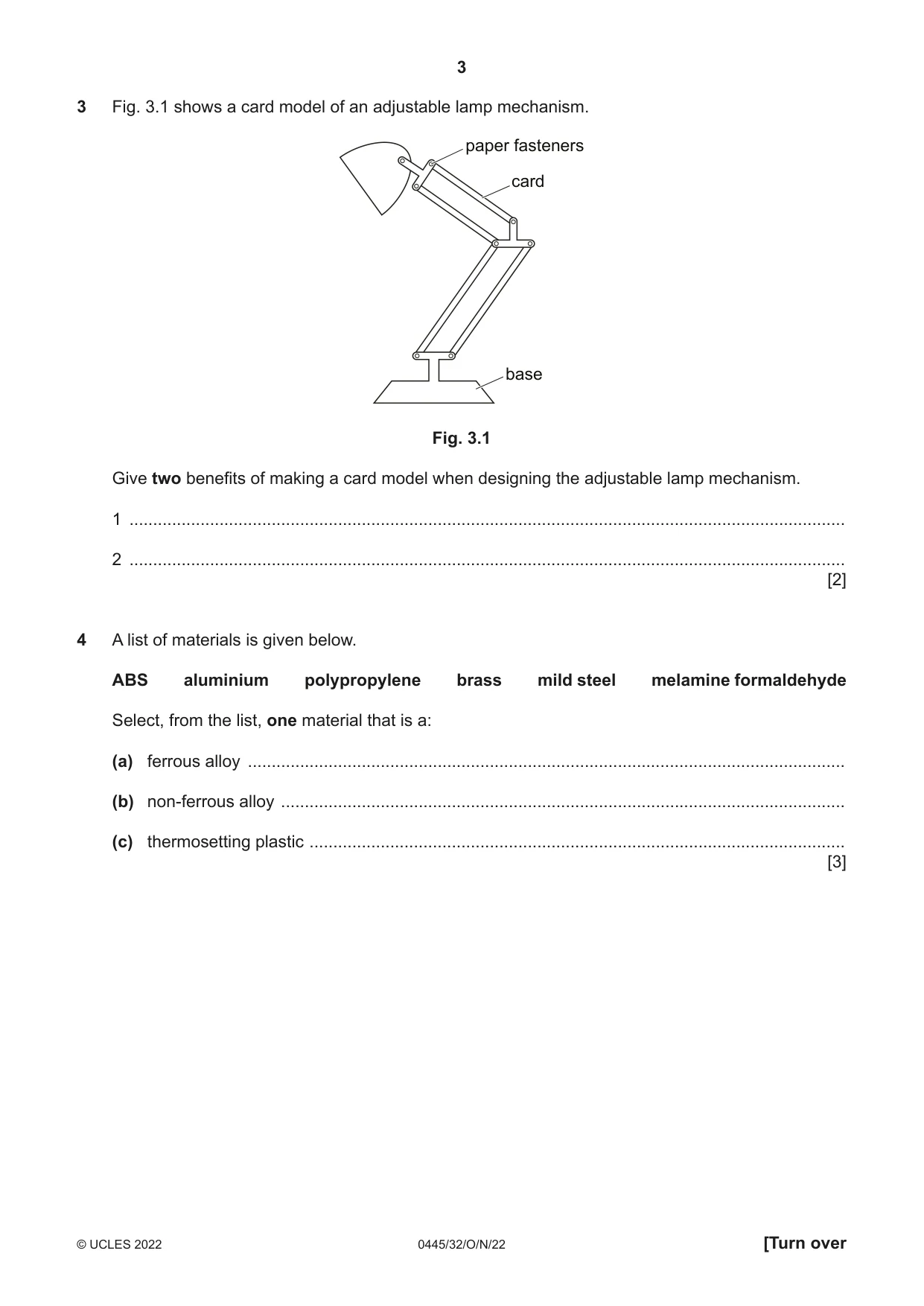
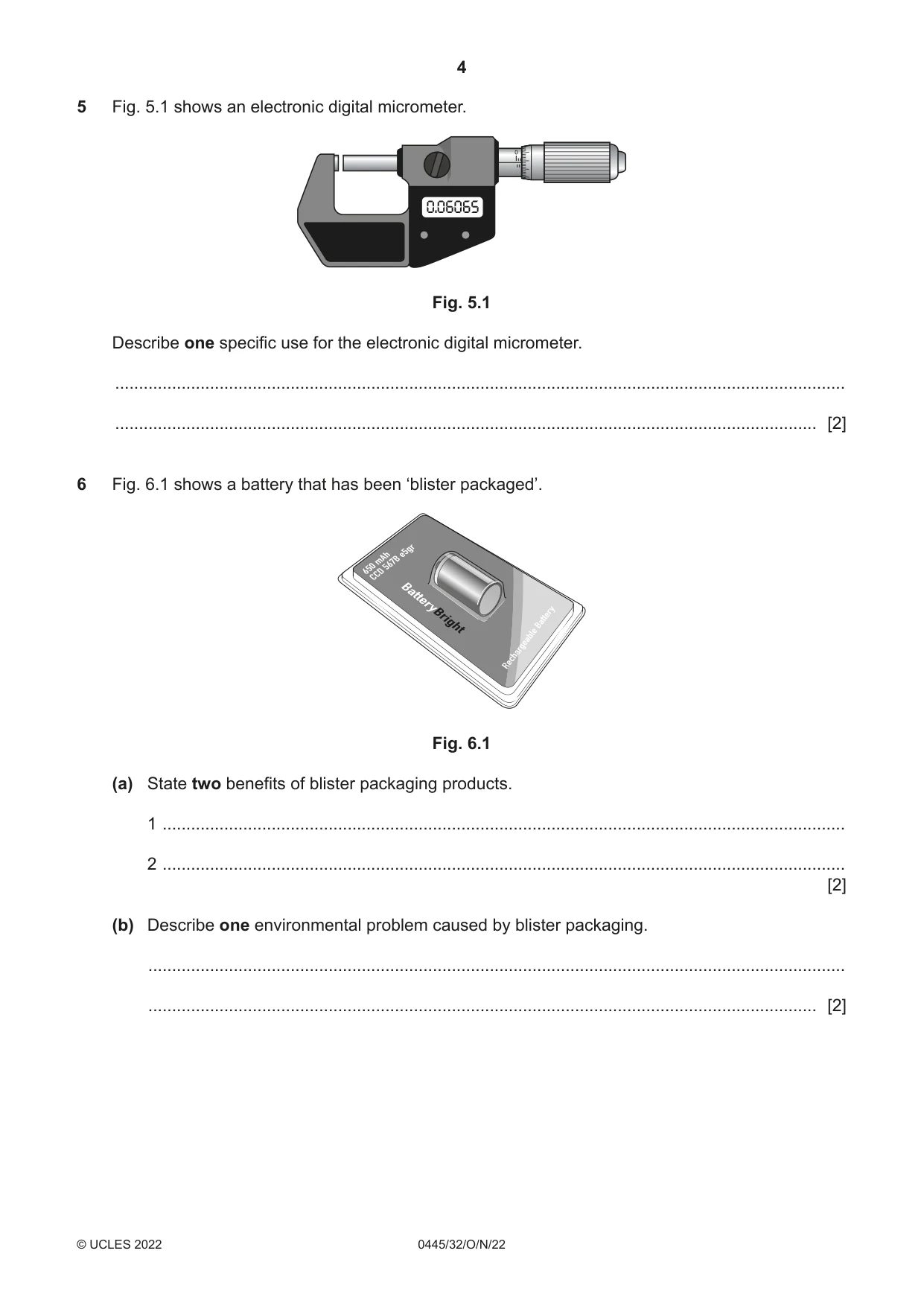
Mark scheme9 pages
Answers below. Sit the paper first if you are practising.
Questions as text
Q1 · A set of steps used in a swimming pool
1 Fig. 1.1 shows a set of steps used in a swimming pool. support rail step Fig. 1.1 Give the name of: (a) a suitable specific metal that could be used to make the support rails ............................................................................................................................................. [1] (b) a specific plastic for the steps. ............................................................................................................................................. [1]
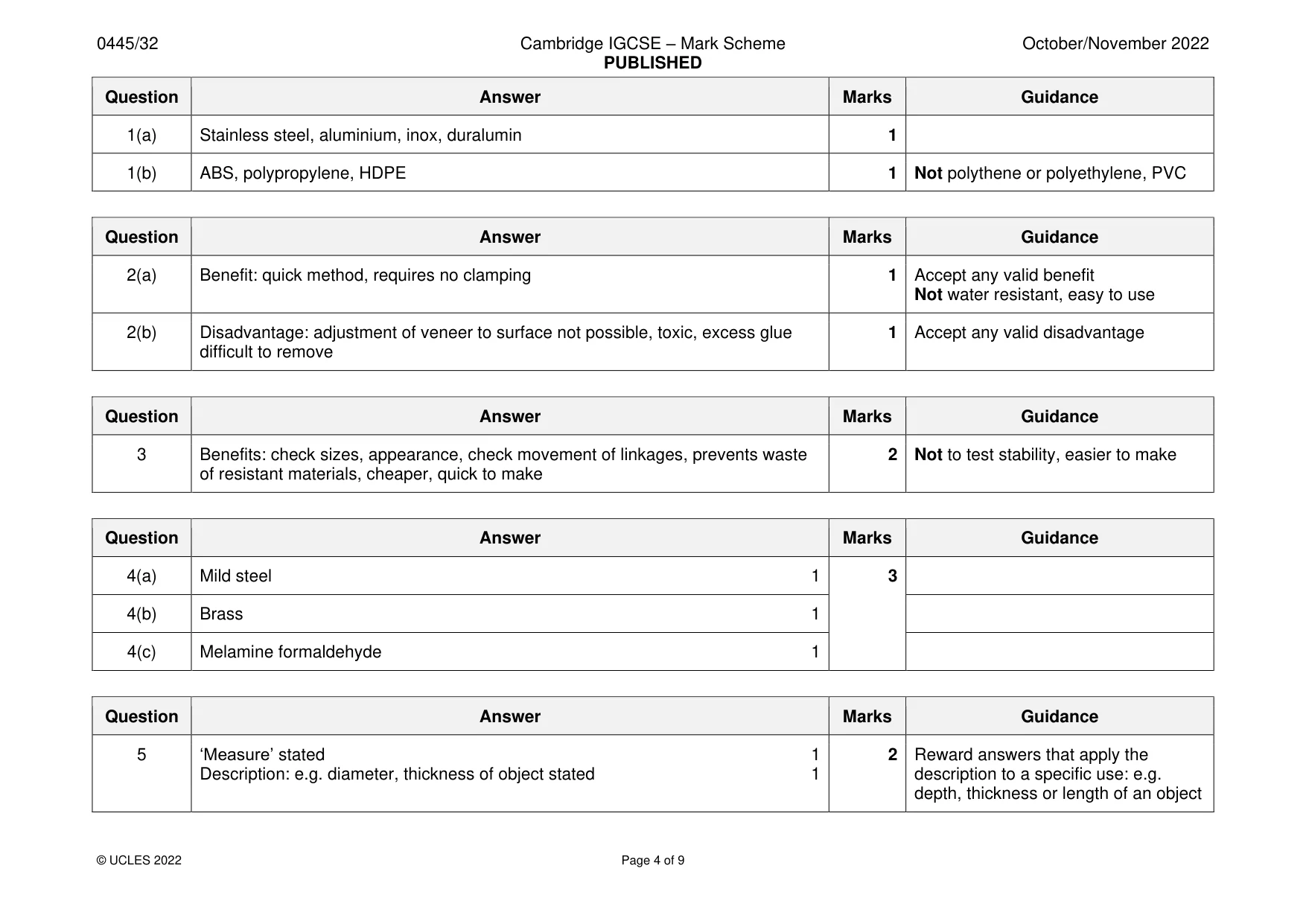
Mark scheme: Question Answer Marks Guidance 1(a) Stainless steel, aluminium, inox, duralumin 1 1(b) ABS, polypropylene, HDPE 1 Not polythene or polyethylene, PVC
Q2 · Part of a manufactured board
2 Fig. 2.1 shows part of a manufactured board. The board will be covered with a veneer. veneer Fig. 2.1 (a) Give one benefit of using a contact adhesive to join the veneer to the manufactured board. ............................................................................................................................................. [1] (b) Give one drawback of using a contact adhesive to join the veneer to the manufactured board. ............................................................................................................................................. [1]
Mark scheme: 2(a) Benefit: quick method, requires no clamping 1 Accept any valid benefit Not water resistant, easy to use 2(b) Disadvantage: adjustment of veneer to surface not possible, toxic, excess glue 1 Accept any valid disadvantage difficult to remove
Q3 · A card model of an adjustable lamp mechanism
3 Fig. 3.1 shows a card model of an adjustable lamp mechanism. paper fasteners card base Fig. 3.1 Give two benefits of making a card model when designing the adjustable lamp mechanism. 1 ....................................................................................................................................................... 2 ....................................................................................................................................................... [2]
Mark scheme: 3 Benefits: check sizes, appearance, check movement of linkages, prevents waste 2 Not to test stability, easier to make of resistant materials, cheaper, quick to make
Q4 · A list of materials is given below
4 A list of materials is given below. ABS aluminium polypropylene brass mild steel melamine formaldehyde Select, from the list, one material that is a: (a) ferrous alloy .............................................................................................................................. (b) non-ferrous alloy ....................................................................................................................... (c) thermosetting plastic ................................................................................................................. [3]
Mark scheme: 4(a) Mild steel 1 3 4(b) Brass 1 4(c) Melamine formaldehyde 1
Q5 · An electronic digital micrometer
5 Fig. 5.1 shows an electronic digital micrometer. 0.06065 Fig. 5.1 Describe one specific use for the electronic digital micrometer. .......................................................................................................................................................... .................................................................................................................................................... [2]
Mark scheme: 5 ‘Measure’ stated 1 2 Reward answers that apply the Description: e.g. diameter, thickness of object stated 1 description to a specific use: e.g. depth, thickness or length of an object
Q6 · A battery that has been ‘blister packaged’
6 Fig. 6.1 shows a battery that has been ‘blister packaged’. e5gr mAh567B 650 CCD Fig. 6.1 (a) State two benefits of blister packaging products. 1 ................................................................................................................................................ 2 ................................................................................................................................................ [2] (b) Describe one environmental problem caused by blister packaging. ................................................................................................................................................... ............................................................................................................................................. [2]
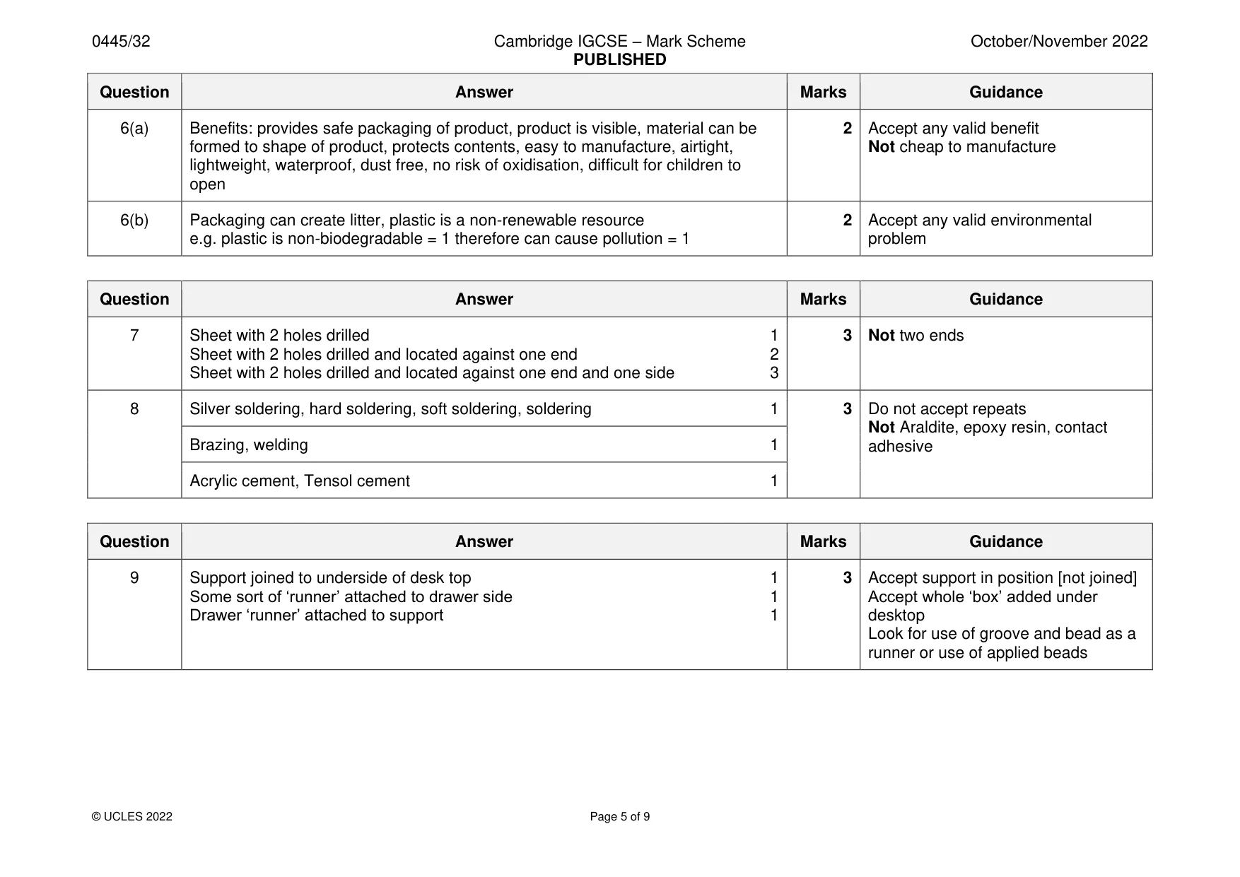
Mark scheme: 6(a) Benefits: provides safe packaging of product, product is visible, material can be 2 Accept any valid benefit formed to shape of product, protects contents, easy to manufacture, airtight, Not cheap to manufacture lightweight, waterproof, dust free, no risk of oxidisation, difficult for children to open 6(b) Packaging can create litter, plastic is a non-renewable resource 2 Accept any valid environmental e.g. plastic is non-biodegradable = 1 therefore can cause pollution = 1 problem
Q7 · Two pieces of hardwood that will be joined by means of a dowel joint
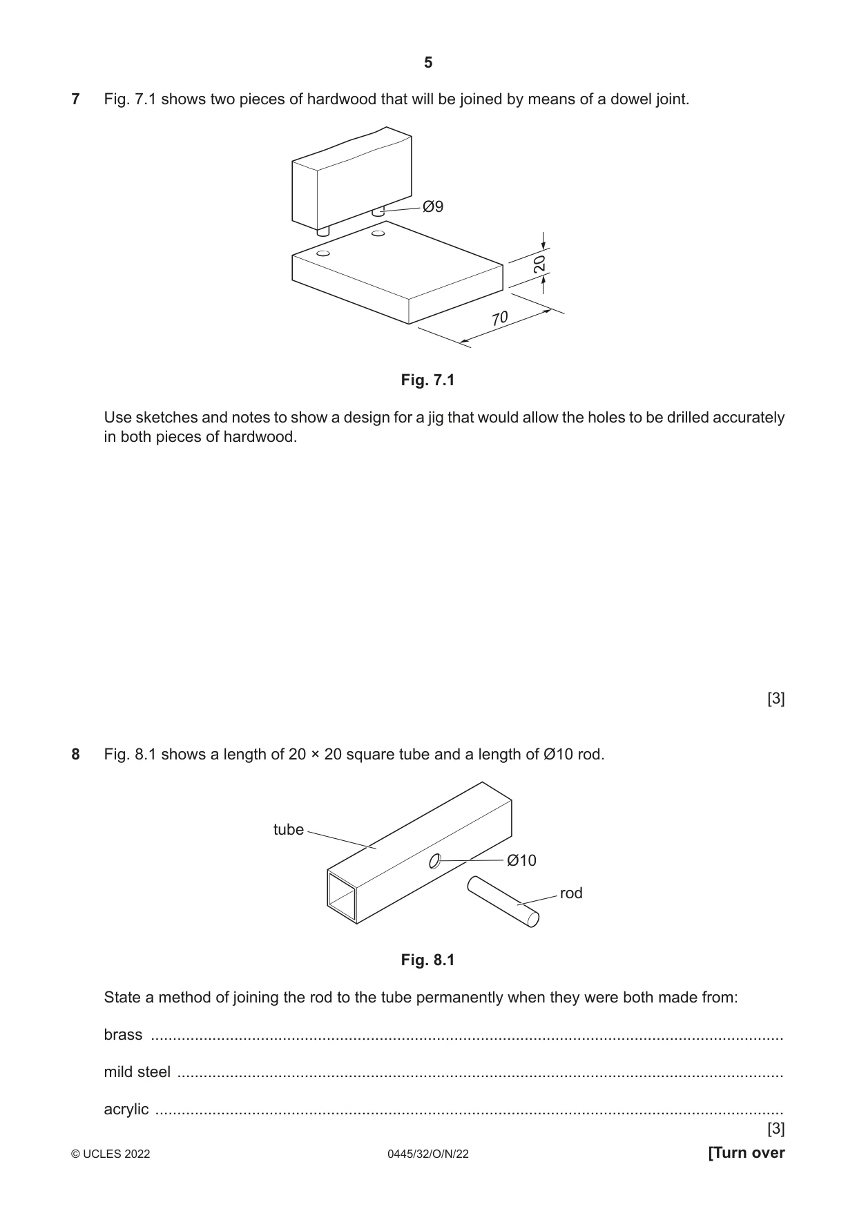
7 Fig. 7.1 shows two pieces of hardwood that will be joined by means of a dowel joint. Ø9 20 70 Fig. 7.1 Use sketches and notes to show a design for a jig that would allow the holes to be drilled accurately in both pieces of hardwood. [3]
Mark scheme: 7 Sheet with 2 holes drilled 1 3 Not two ends Sheet with 2 holes drilled and located against one end 2 Sheet with 2 holes drilled and located against one end and one side 3
Q8 · A length of 20 × 20 square tube and a length of Ø10 rod
8 Fig. 8.1 shows a length of 20 × 20 square tube and a length of Ø10 rod. tube Ø10 rod Fig. 8.1 State a method of joining the rod to the tube permanently when they were both made from: brass ................................................................................................................................................ mild steel .......................................................................................................................................... acrylic ............................................................................................................................................... [3]
Mark scheme: 8 Silver soldering, hard soldering, soft soldering, soldering 1 3 Do not accept repeats Not Araldite, epoxy resin, contact Brazing, welding 1 adhesive Acrylic cement, Tensol cement 1
Q9 · A wooden drawer and the top of a desk
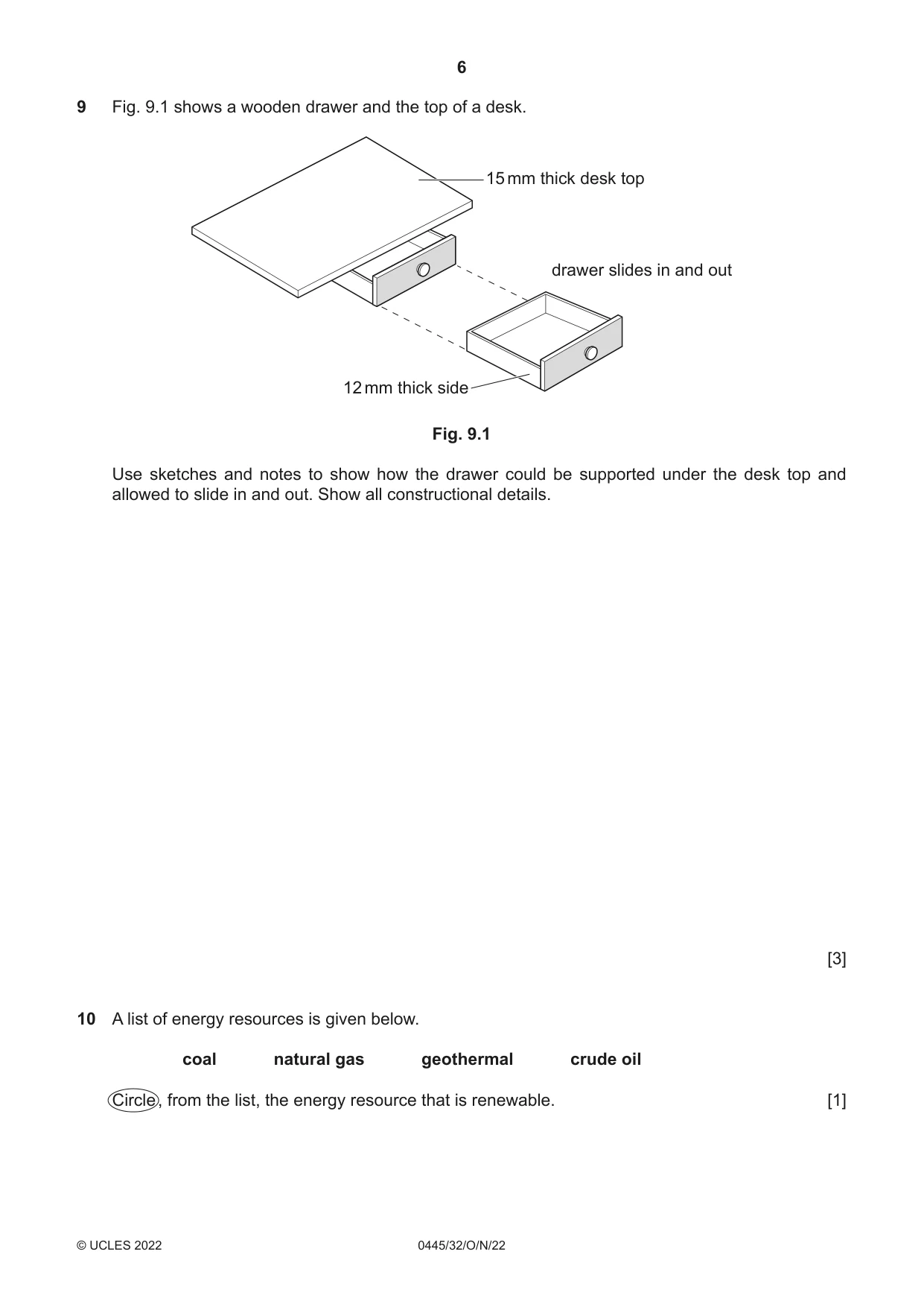
9 Fig. 9.1 shows a wooden drawer and the top of a desk. 15 mm thick desk top drawer slides in and out 12 mm thick side Fig. 9.1 Use sketches and notes to show how the drawer could be supported under the desk top and allowed to slide in and out. Show all constructional details. [3]
Mark scheme: 9 Support joined to underside of desk top 1 3 Accept support in position [not joined] Some sort of ‘runner’ attached to drawer side 1 Accept whole ‘box’ added under Drawer ‘runner’ attached to support 1 desktop Look for use of groove and bead as a runner or use of applied beads
Q10 · A list of energy resources is given below
10 A list of energy resources is given below. coal natural gas geothermal crude oil Circle , from the list, the energy resource that is renewable. [1]
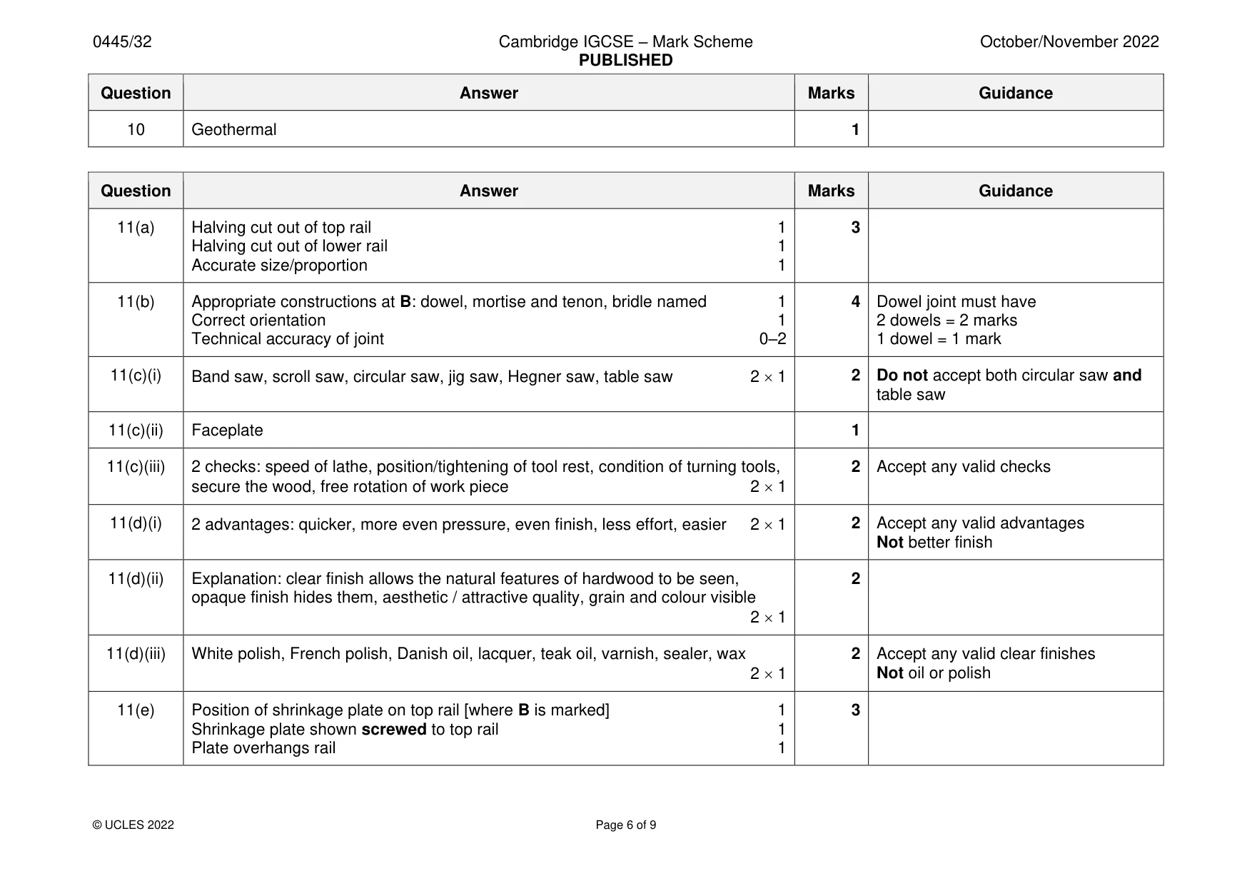
Mark scheme: 10 Geothermal 1
Q11 · A small table made from hardwood
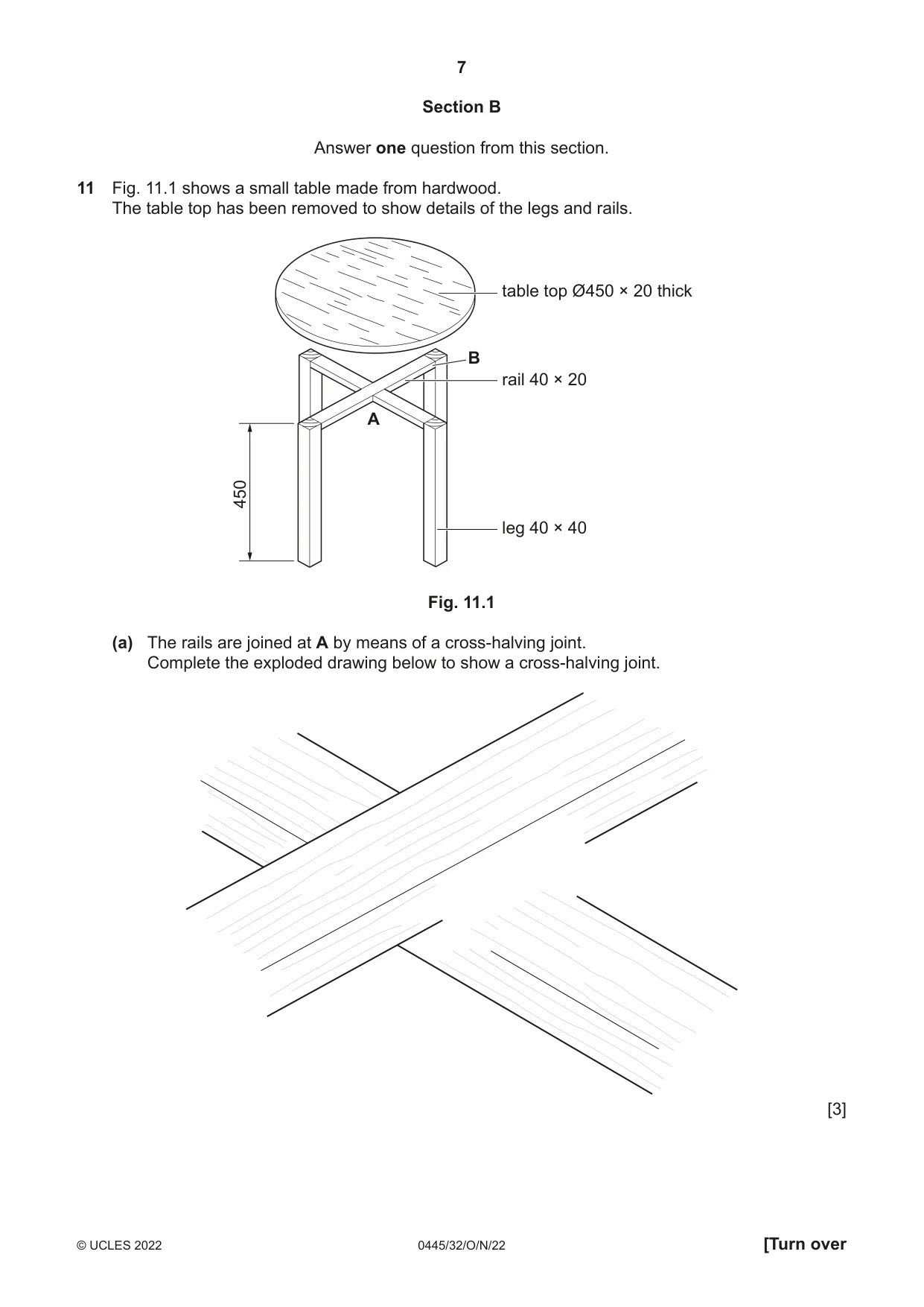
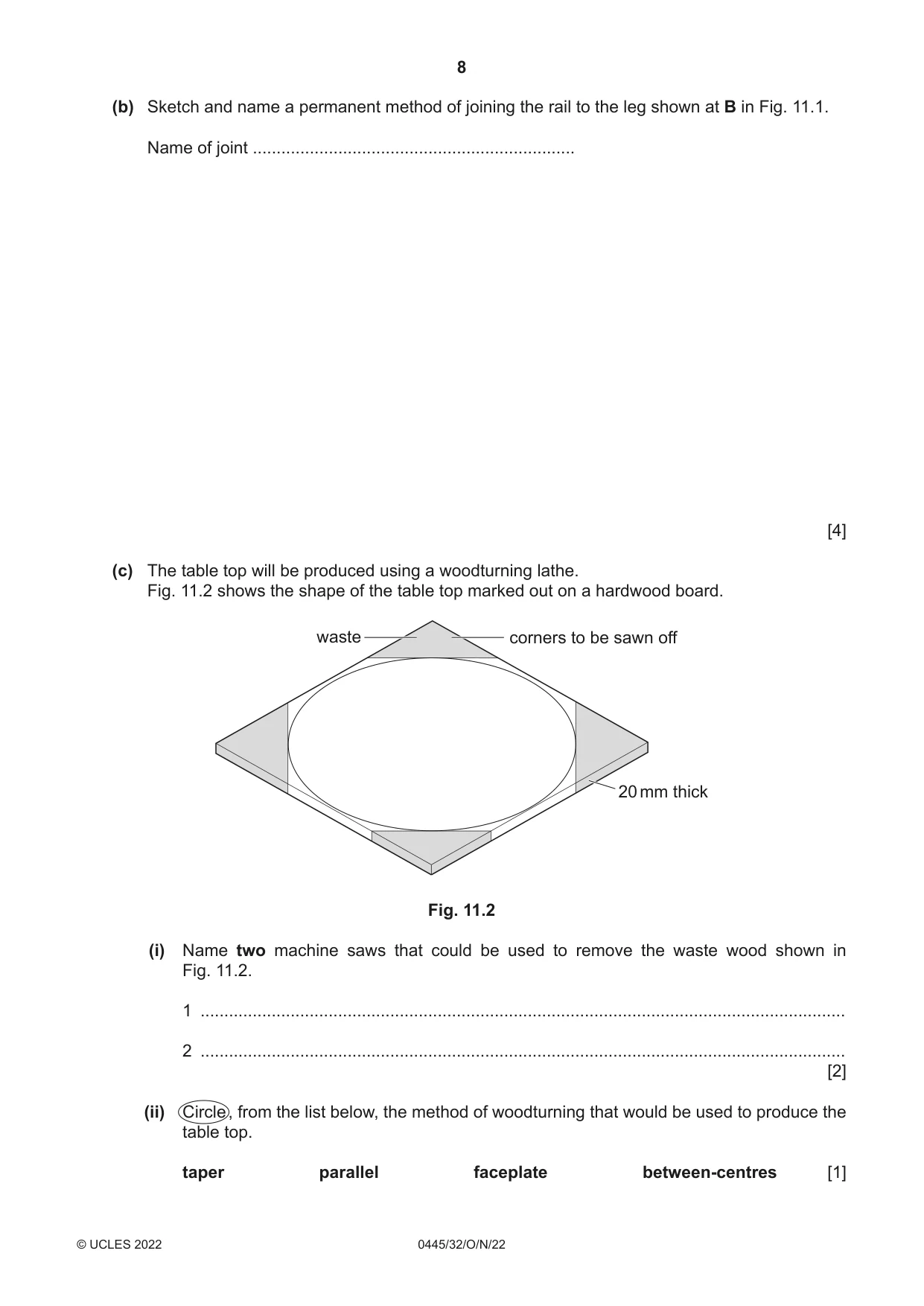
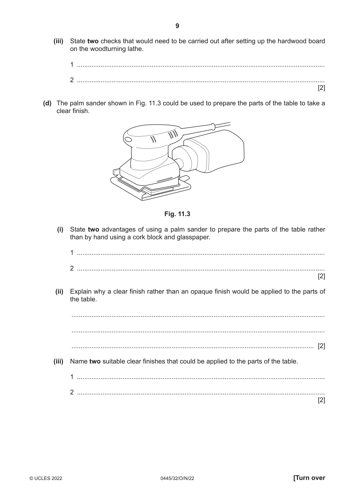
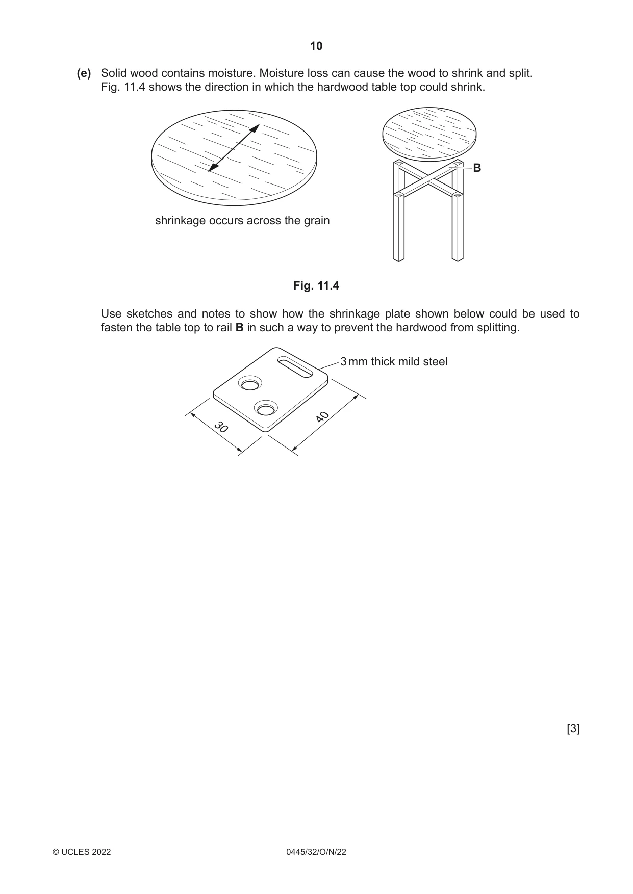
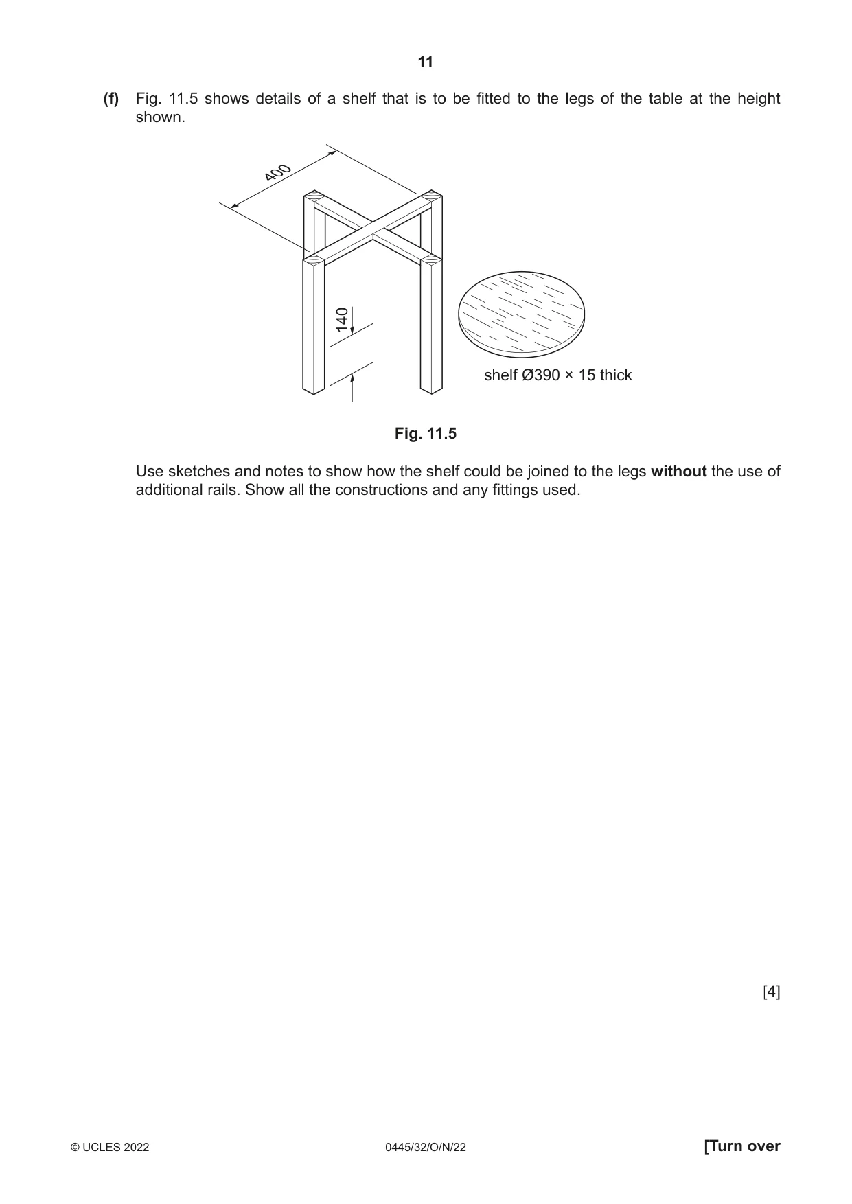
11 Fig. 11.1 shows a small table made from hardwood. The table top has been removed to show details of the legs and rails. table top Ø450 × 20 thick B rail 40 × 20 A 450 leg 40 × 40 Fig. 11.1 (a) The rails are joined at A by means of a cross-halving joint. Complete the exploded drawing below to show a cross-halving joint. [3] (b) Sketch and name a permanent method of joining the rail to the leg shown at B in Fig. 11.1. Name of joint .................................................................... [4] (c) The table top will be produced using a woodturning lathe. Fig. 11.2 shows the shape of the table top marked out on a hardwood board. waste corners to be sawn off 20 mm thick Fig. 11.2 (i) Name two machine saws that could be used to remove the waste wood shown in Fig. 11.2. 1 ........................................................................................................................................ 2 ........................................................................................................................................ [2] (ii) Circle , from the list below, the method of woodturning that would be used to produce the table top. taper parallel faceplate between-centres [1] (iii) State two checks that would need to be carried out after setting up the hardwood board on the woodturning lathe. 1 ........................................................................................................................................ 2 ........................................................................................................................................ [2] (d) The palm sander shown in Fig. 11.3 could be used to prepare the parts of the table to take a clear finish. Fig. 11.3 (i) State two advantages of using a palm sander to prepare the parts of the table rather than by hand using a cork block and glasspaper. 1 ........................................................................................................................................ 2 ........................................................................................................................................ [2] (ii) Explain why a clear finish rather than an opaque finish would be applied to the parts of the table. ........................................................................................................................................... ........................................................................................................................................... ..................................................................................................................................... [2] (iii) Name two suitable clear finishes that could be applied to the parts of the table. 1 ........................................................................................................................................ 2 ........................................................................................................................................ [2] (e) Solid wood contains moisture. Moisture loss can cause the wood to shrink and split. Fig. 11.4 shows the direction in which the hardwood table top could shrink. B shrinkage occurs across the grain Fig. 11.4 Use sketches and notes to show how the shrinkage plate shown below could be used to fasten the table top to rail B in such a way to prevent the hardwood from splitting. 3 mm thick mild steel 40 30 [3] (f) Fig. 11.5 shows details of a shelf that is to be fitted to the legs of the table at the height shown. 400 140 shelf Ø390 × 15 thick Fig. 11.5 Use sketches and notes to show how the shelf could be joined to the legs without the use of additional rails. Show all the constructions and any fittings used. [4]
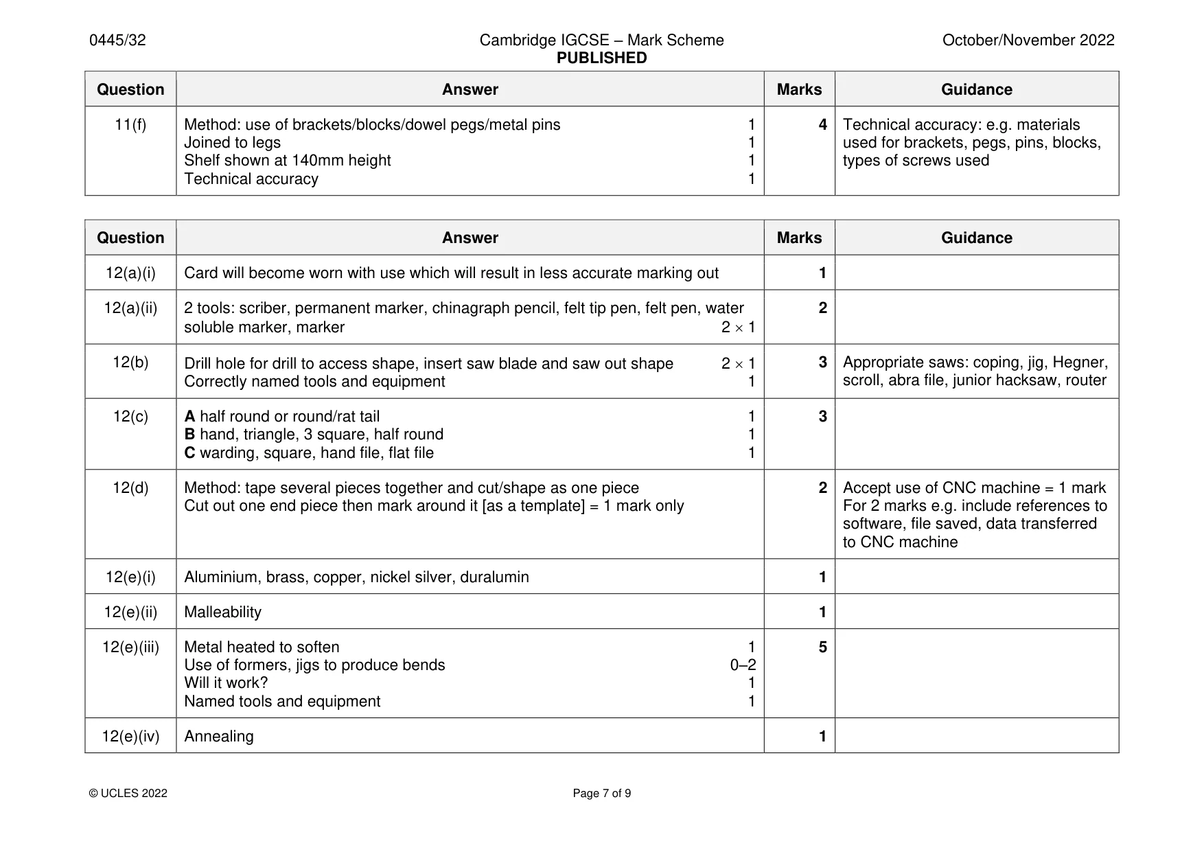
Mark scheme: 11(a) Halving cut out of top rail 1 3 Halving cut out of lower rail 1 Accurate size/proportion 1 11(b) Appropriate constructions at B: dowel, mortise and tenon, bridle named 1 4 Dowel joint must have Correct orientation 1 2 dowels = 2 marks Technical accuracy of joint 0–2 1 dowel = 1 mark 11(c)(i) Band saw, scroll saw, circular saw, jig saw, Hegner saw, table saw 2 1 2 Do not accept both circular saw and table saw 11(c)(ii) Faceplate 1 11(c)(iii) 2 checks: speed of lathe, position/tightening of tool rest, condition of turning tools, 2 Accept any valid checks secure the wood, free rotation of work piece 2 1 11(d)(i) 2 advantages: quicker, more even pressure, even finish, less effort, easier 2 1 2 Accept any valid advantages Not better finish 11(d)(ii) Explanation: clear finish allows the natural features of hardwood to be seen, 2 opaque finish hides them, aesthetic / attractive quality, grain and colour visible 2 1 11(d)(iii) White polish, French polish, Danish oil, lacquer, teak oil, varnish, sealer, wax 2 Accept any valid clear finishes 2 1 Not oil or polish 11(e) Position of shrinkage plate on top rail [where B is marked] 1 3 Shrinkage plate shown screwed to top rail 1 Plate overhangs rail 1 11(f) Method: use of brackets/blocks/dowel pegs/metal pins 1 4 Technical accuracy: e.g. materials Joined to legs 1 used for brackets, pegs, pins, blocks, Shelf shown at 140mm height 1 types of screws used Technical accuracy 1
Q12 · A book stand that will be used to display books in a school library
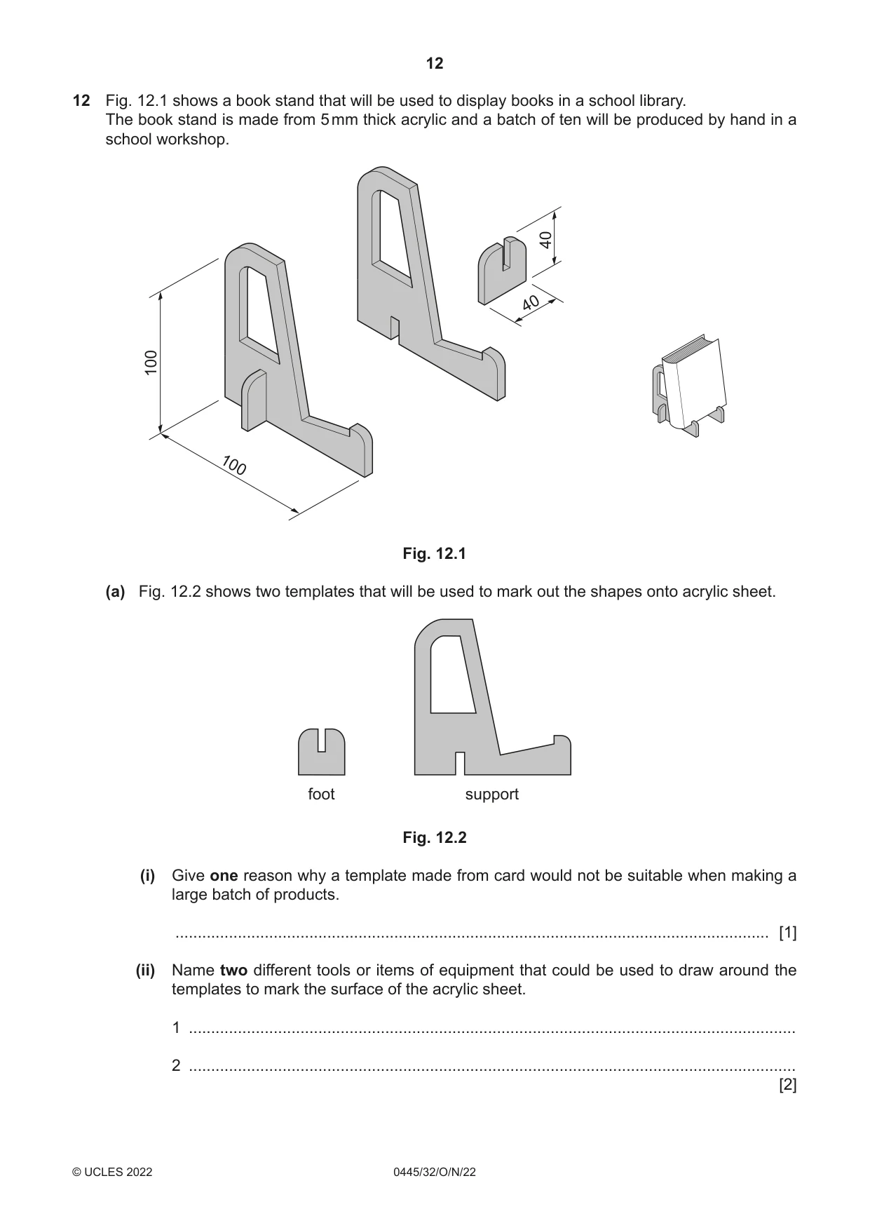
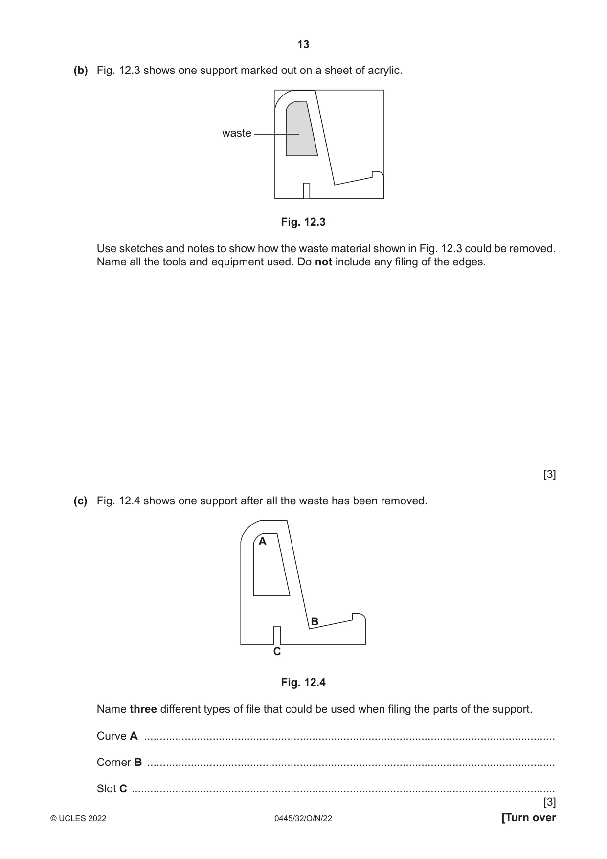
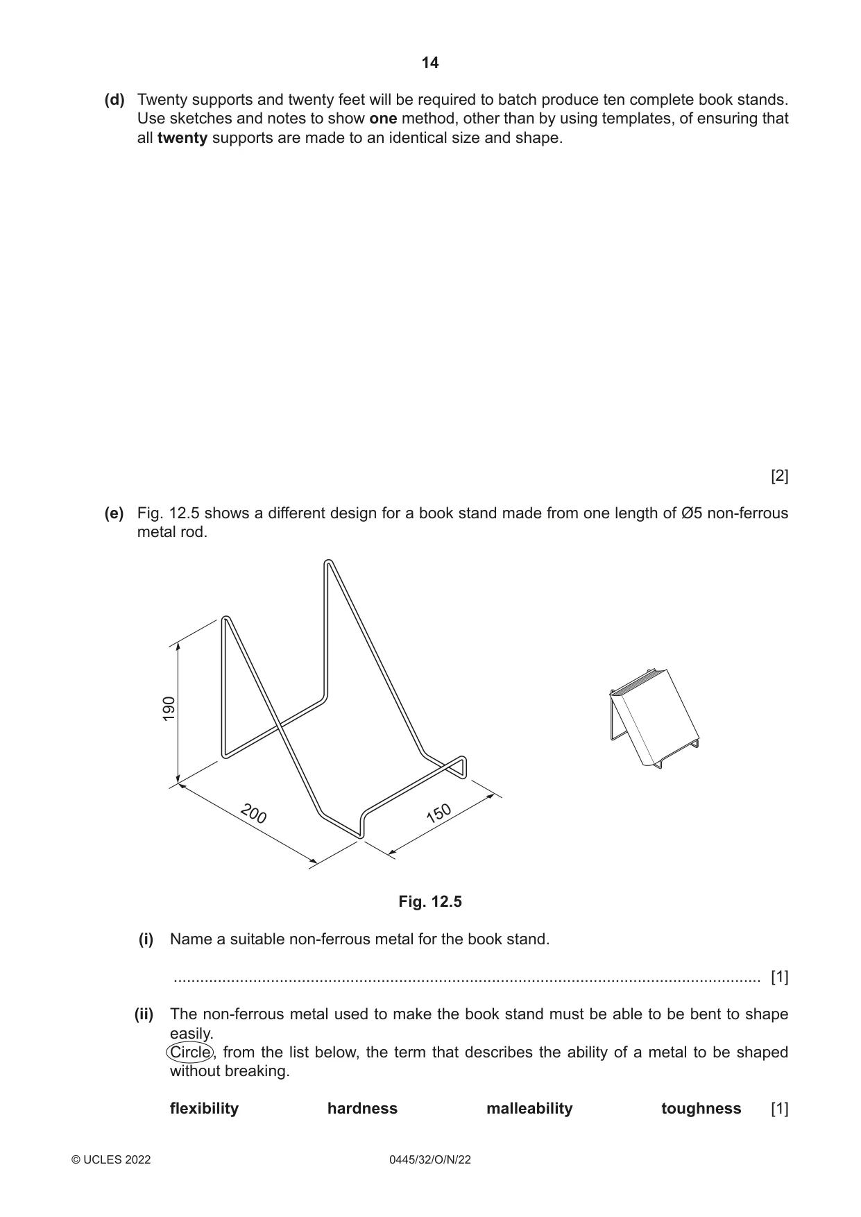
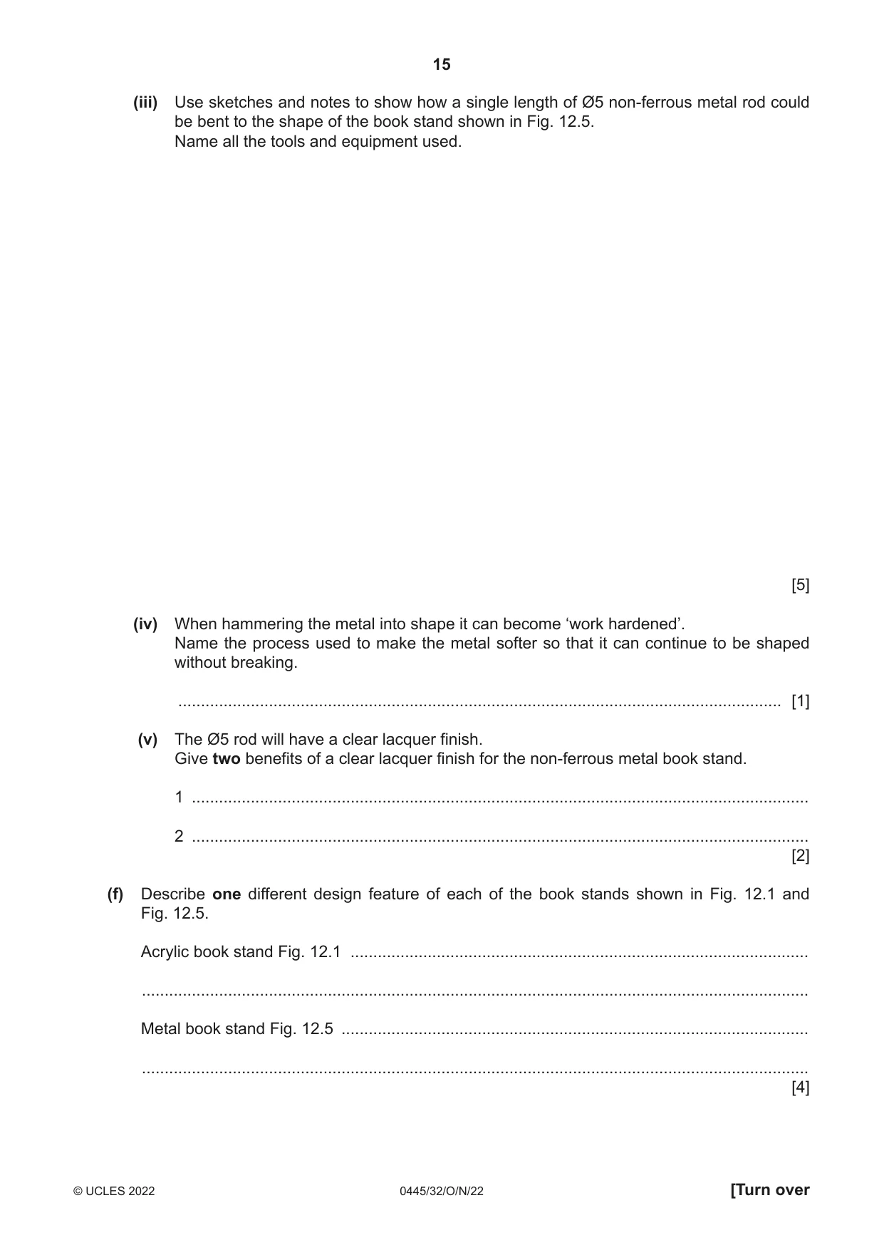
12 Fig. 12.1 shows a book stand that will be used to display books in a school library. The book stand is made from 5 mm thick acrylic and a batch of ten will be produced by hand in a school workshop. 40 40 100 100 Fig. 12.1 (a) Fig. 12.2 shows two templates that will be used to mark out the shapes onto acrylic sheet. foot support Fig. 12.2 (i) Give one reason why a template made from card would not be suitable when making a large batch of products. ..................................................................................................................................... [1] (ii) Name two different tools or items of equipment that could be used to draw around the templates to mark the surface of the acrylic sheet. 1 ........................................................................................................................................ 2 ........................................................................................................................................ [2] (b) Fig. 12.3 shows one support marked out on a sheet of acrylic. waste Fig. 12.3 Use sketches and notes to show how the waste material shown in Fig. 12.3 could be removed. Name all the tools and equipment used. Do not include any filing of the edges. [3] (c) Fig. 12.4 shows one support after all the waste has been removed. A B C Fig. 12.4 Name three different types of file that could be used when filing the parts of the support. Curve A .................................................................................................................................... Corner B ................................................................................................................................... Slot C ........................................................................................................................................ [3] (d) Twenty supports and twenty feet will be required to batch produce ten complete book stands. Use sketches and notes to show one method, other than by using templates, of ensuring that all twenty supports are made to an identical size and shape. [2] (e) Fig. 12.5 shows a different design for a book stand made from one length of Ø5 non-ferrous metal rod. 190 200 150 Fig. 12.5 (i) Name a suitable non-ferrous metal for the book stand. ..................................................................................................................................... [1] (ii) The non-ferrous metal used to make the book stand must be able to be bent to shape easily. Circle , from the list below, the term that describes the ability of a metal to be shaped without breaking. flexibility hardness malleability toughness [1] (iii) Use sketches and notes to show how a single length of Ø5 non-ferrous metal rod could be bent to the shape of the book stand shown in Fig. 12.5. Name all the tools and equipment used. [5] (iv) When hammering the metal into shape it can become ‘work hardened’. Name the process used to make the metal softer so that it can continue to be shaped without breaking. ..................................................................................................................................... [1] (v) The Ø5 rod will have a clear lacquer finish. Give two benefits of a clear lacquer finish for the non-ferrous metal book stand. 1 ........................................................................................................................................ 2 ........................................................................................................................................ [2] (f) Describe one different design feature of each of the book stands shown in Fig. 12.1 and Fig. 12.5. Acrylic book stand Fig. 12.1 ..................................................................................................... ................................................................................................................................................... Metal book stand Fig. 12.5 ....................................................................................................... ................................................................................................................................................... [4]
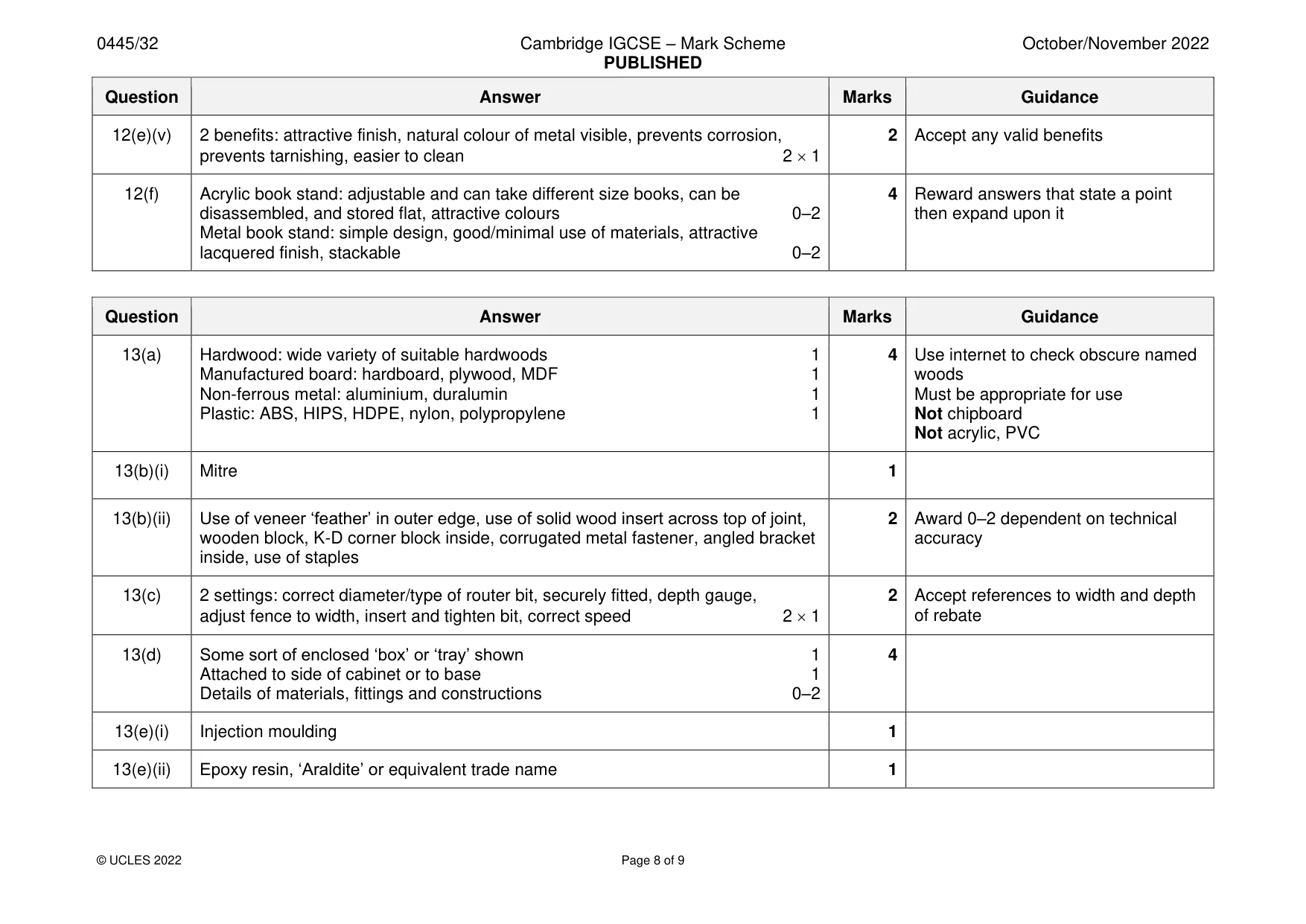
Mark scheme: 12(a)(i) Card will become worn with use which will result in less accurate marking out 1 12(a)(ii) 2 tools: scriber, permanent marker, chinagraph pencil, felt tip pen, felt pen, water 2 soluble marker, marker 2 1 12(b) Drill hole for drill to access shape, insert saw blade and saw out shape 2 1 3 Appropriate saws: coping, jig, Hegner, Correctly named tools and equipment 1 scroll, abra file, junior hacksaw, router 12(c) A half round or round/rat tail 1 3 B hand, triangle, 3 square, half round 1 C warding, square, hand file, flat file 1 12(d) Method: tape several pieces together and cut/shape as one piece 2 Accept use of CNC machine = 1 mark Cut out one end piece then mark around it [as a template] = 1 mark only For 2 marks e.g. include references to software, file saved, data transferred to CNC machine 12(e)(i) Aluminium, brass, copper, nickel silver, duralumin 1 12(e)(ii) Malleability 1 12(e)(iii) Metal heated to soften 1 5 Use of formers, jigs to produce bends 0–2 Will it work? 1 Named tools and equipment 1 12(e)(iv) Annealing 1 12(e)(v) 2 benefits: attractive finish, natural colour of metal visible, prevents corrosion, 2 Accept any valid benefits prevents tarnishing, easier to clean 2 1 12(f) Acrylic book stand: adjustable and can take different size books, can be 4 Reward answers that state a point disassembled, and stored flat, attractive colours 0–2 then expand upon it Metal book stand: simple design, good/minimal use of materials, attractive lacquered finish, stackable 0–2
Q13 · An incomplete design for a table football game
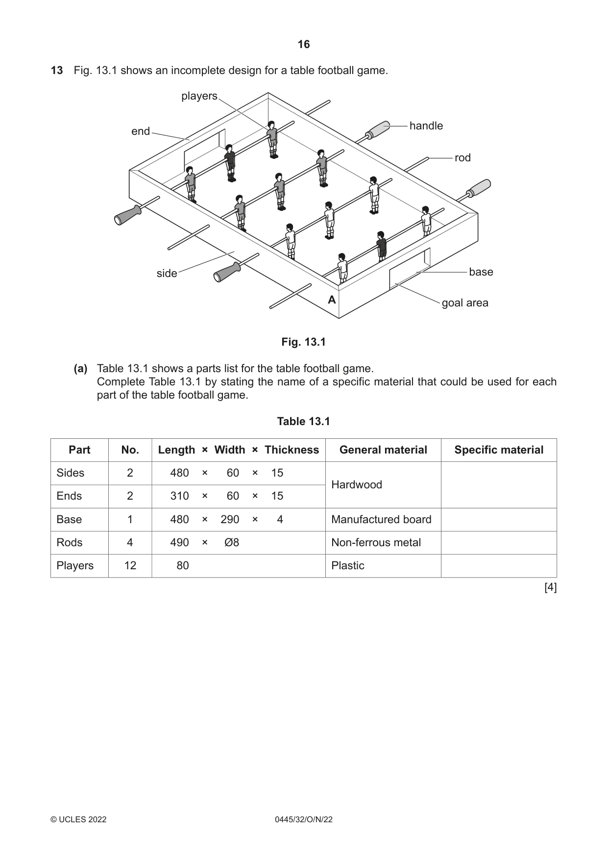
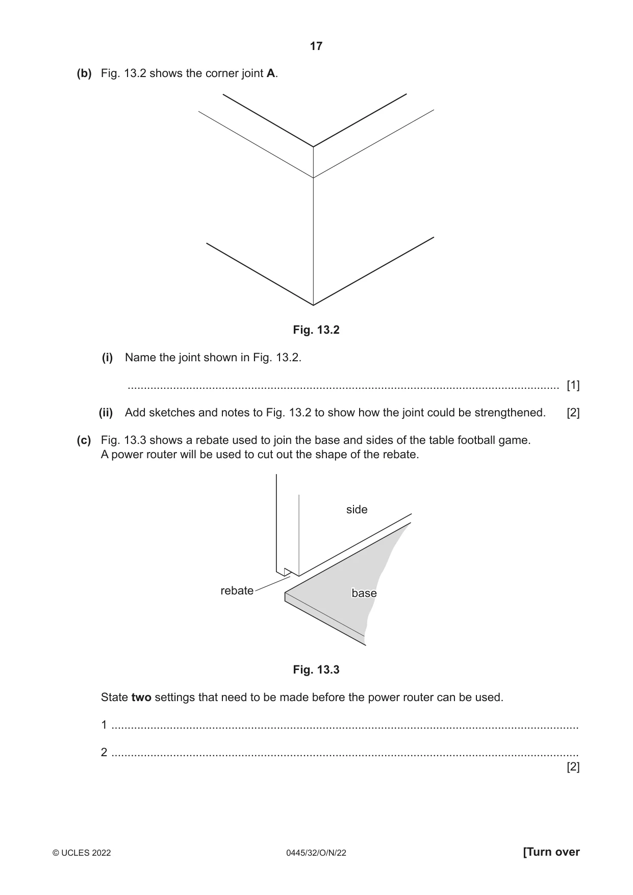
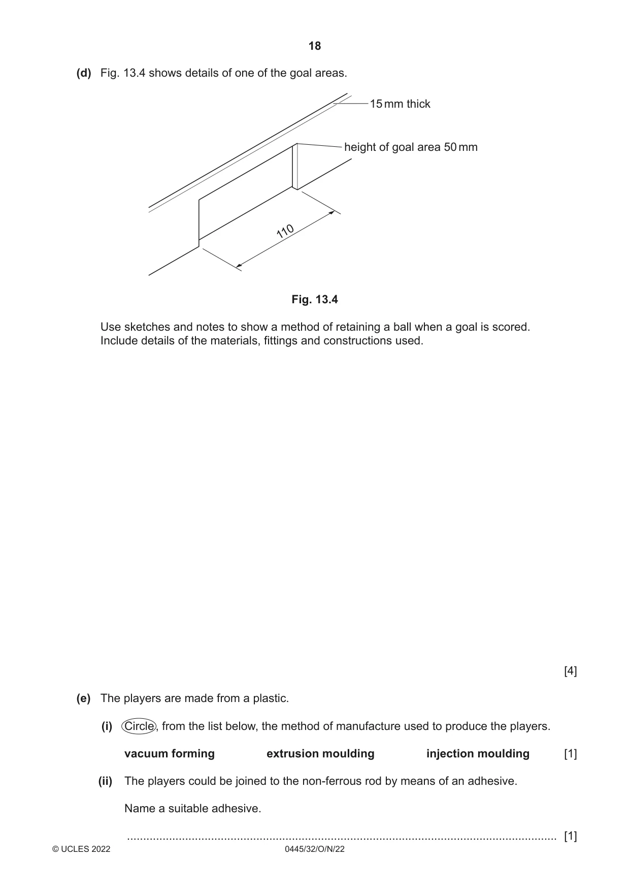
13 Fig. 13.1 shows an incomplete design for a table football game. players handle end rod side base A goal area Fig. 13.1 (a) Table 13.1 shows a parts list for the table football game. Complete Table 13.1 by stating the name of a specific material that could be used for each part of the table football game. Table 13.1 Part No. Length × Width × Thickness General material Specific material Sides 2 480 × 60 × 15 Hardwood Ends 2 310 × 60 × 15 Base 1 480 × 290 × 4 Manufactured board Rods 4 490 × Ø8 Non-ferrous metal Players 12 80 Plastic [4] (b) Fig. 13.2 shows the corner joint A. Fig. 13.2 (i) Name the joint shown in Fig. 13.2. ..................................................................................................................................... [1] (ii) Add sketches and notes to Fig. 13.2 to show how the joint could be strengthened. [2] (c) Fig. 13.3 shows a rebate used to join the base and sides of the table football game. A power router will be used to cut out the shape of the rebate. side rebate basebase Fig. 13.3 State two settings that need to be made before the power router can be used. 1 ................................................................................................................................................ 2 ................................................................................................................................................ [2] (d) Fig. 13.4 shows details of one of the goal areas. 15 mm thick height of goal area 50 mm 110 Fig. 13.4 Use sketches and notes to show a method of retaining a ball when a goal is scored. Include details of the materials, fittings and constructions used. [4] (e) The players are made from a plastic. (i) Circle , from the list below, the method of manufacture used to produce the players. vacuum forming extrusion moulding injection moulding [1] (ii) The players could be joined to the non-ferrous rod by means of an adhesive. Name a suitable adhesive.
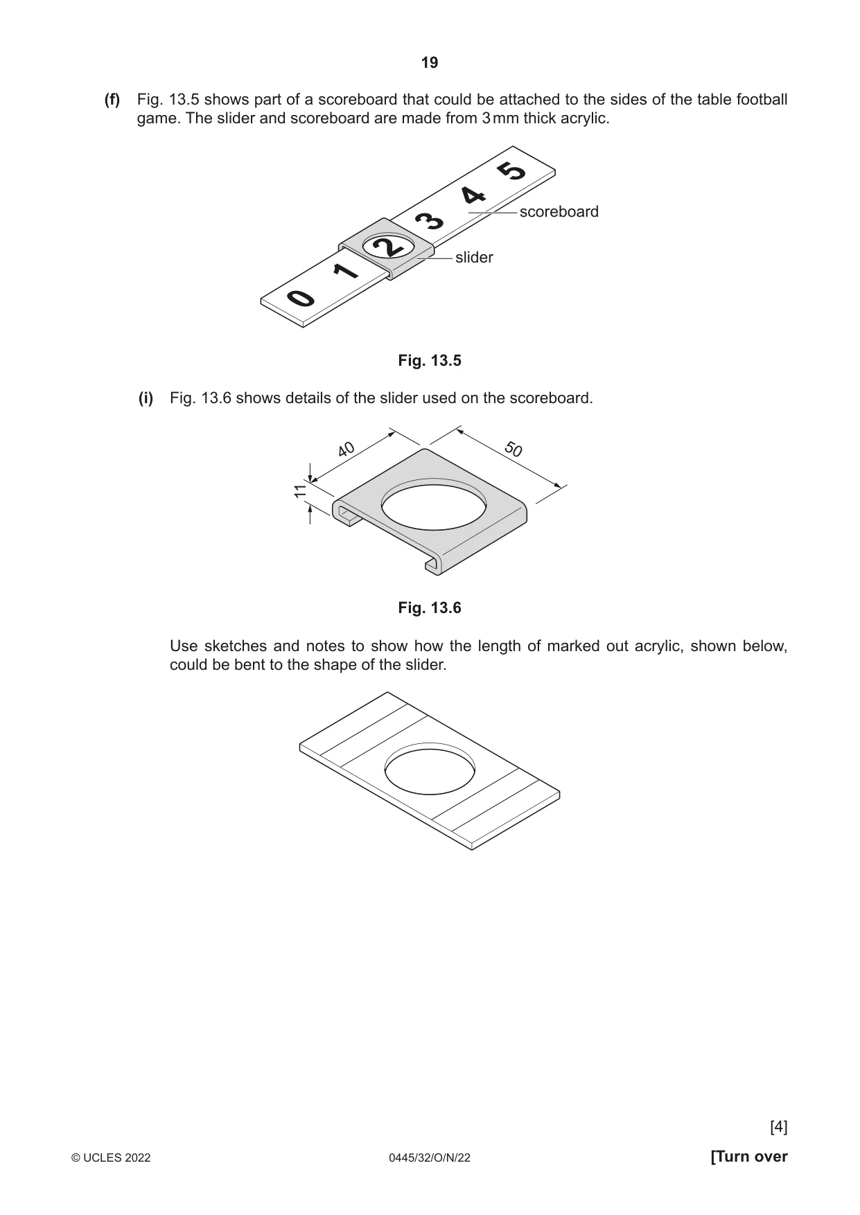
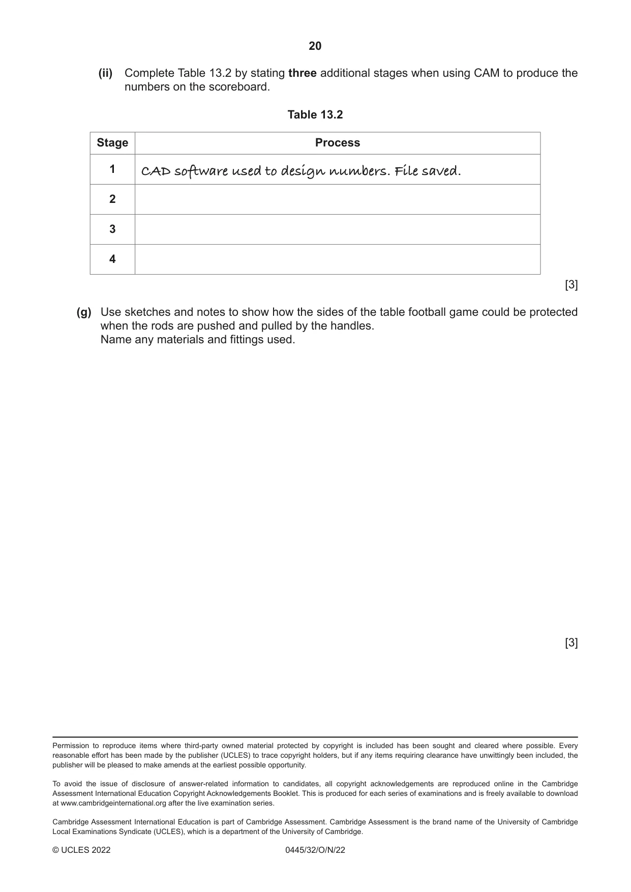
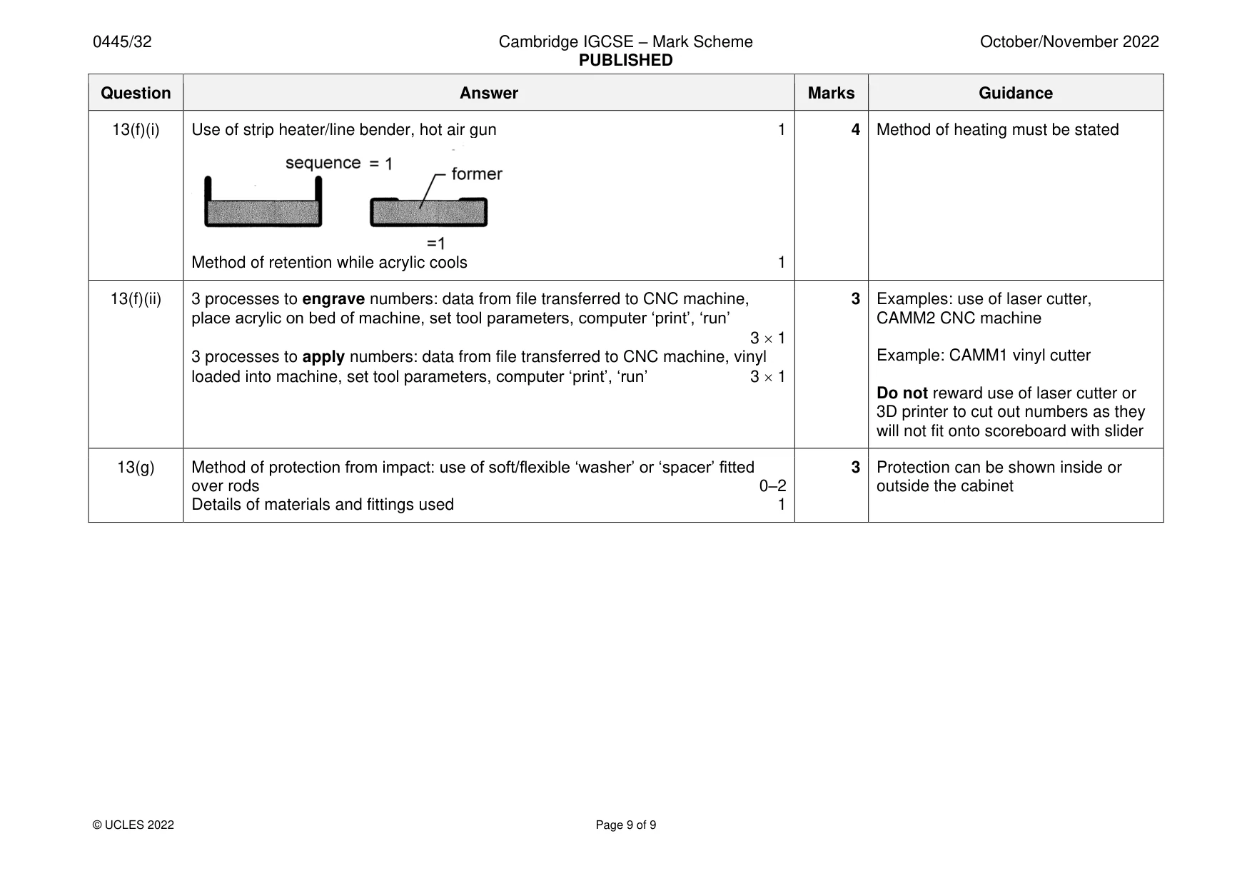
Mark scheme: 13(a) Hardwood: wide variety of suitable hardwoods 1 4 Use internet to check obscure named Manufactured board: hardboard, plywood, MDF 1 woods Non-ferrous metal: aluminium, duralumin 1 Must be appropriate for use Plastic: ABS, HIPS, HDPE, nylon, polypropylene 1 Not chipboard Not acrylic, PVC 13(b)(i) Mitre 1 13(b)(ii) Use of veneer ‘feather’ in outer edge, use of solid wood insert across top of joint, 2 Award 0–2 dependent on technical wooden block, K-D corner block inside, corrugated metal fastener, angled bracket accuracy inside, use of staples 13(c) 2 settings: correct diameter/type of router bit, securely fitted, depth gauge, 2 Accept references to width and depth adjust fence to width, insert and tighten bit, correct speed 2 1 of rebate 13(d) Some sort of enclosed ‘box’ or ‘tray’ shown 1 4 Attached to side of cabinet or to base 1 Details of materials, fittings and constructions 0–2 13(e)(i) Injection moulding 1 13(e)(ii) Epoxy resin, ‘Araldite’ or equivalent trade name 1 13(f)(i) Use of strip heater/line bender, hot air gun 1 4 Method of heating must be stated Method of retention while acrylic cools 1 13(f)(ii) 3 processes to engrave numbers: data from file transferred to CNC machine, 3 Examples: use of laser cutter, place acrylic on bed of machine, set tool parameters, computer ‘print’, ‘run’ CAMM2 CNC machine 3 1 3 processes to apply numbers: data from file transferred to CNC machine, vinyl Example: CAMM1 vinyl cutter loaded into machine, set tool parameters, computer ‘print’, ‘run’ 3 1 Do not reward use of laser cutter or 3D printer to cut out numbers as they will not fit onto scoreboard with slider 13(g) Method of protection from impact: use of soft/flexible ‘washer’ or ‘spacer’ fitted 3 Protection can be shown inside or over rods 0–2 outside the cabinet Details of materials and fittings used 1
What was in this paper
The subtopics covered by these 13 questions, and how many questions each got. Open one in a new tab to see every Cambridge question on it.
What you needed in this session
Cambridge’s own grade thresholds for 2022 Oct/Nov, Paper 3 · Variant 2. A higher threshold means an easier paper — the bar moves with how the cohort did.