Cambridge IGCSE Design and Technology 0445 — 2022 Oct/Nov Paper 3 · Variant 3
0445/33/O/N/22 · 13 questions · 50 marks · ≈56 min
The question paper and its mark scheme, free to read here and free to download. This is Cambridge’s own paper, exactly as it was sat.
Question paper28 pages


Mark scheme9 pages
Answers below. Sit the paper first if you are practising.
Questions as text
Q1 · Three fastenings, A, B and C, used to join materials
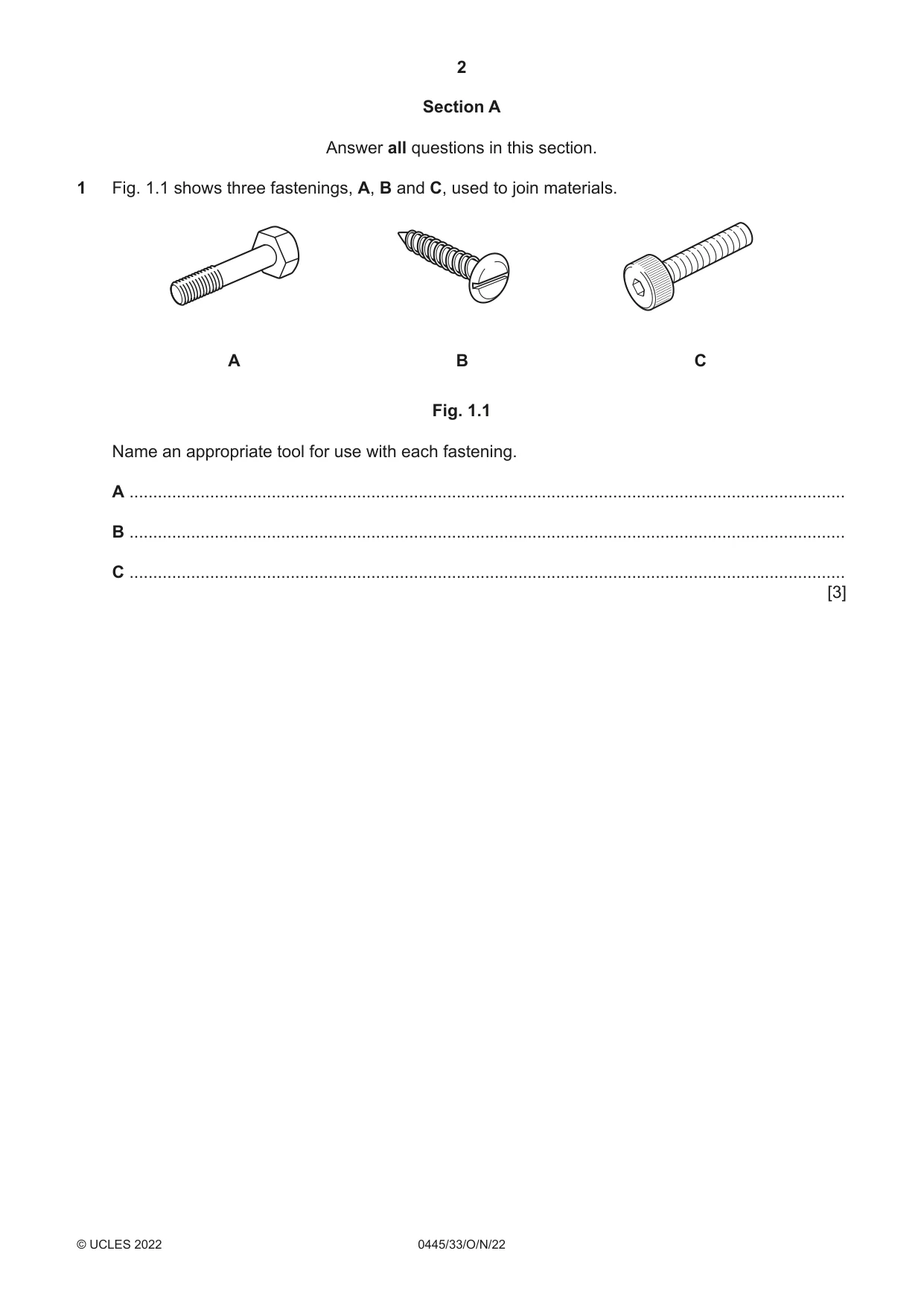
1 Fig. 1.1 shows three fastenings, A, B and C, used to join materials. A B C Fig. 1.1 Name an appropriate tool for use with each fastening. A ....................................................................................................................................................... B ....................................................................................................................................................... C ....................................................................................................................................................... [3]
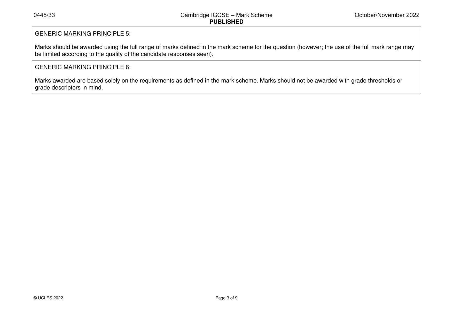
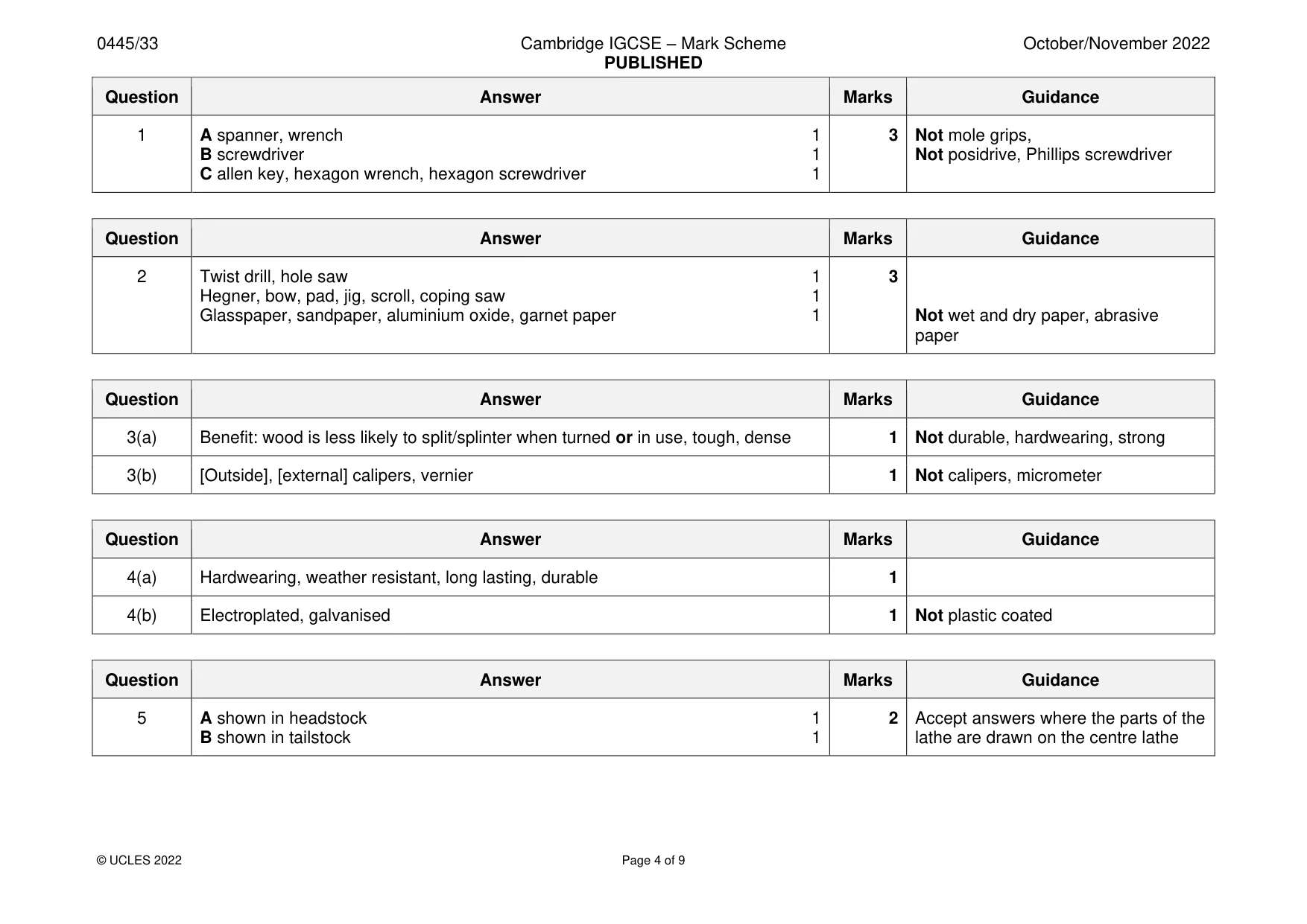
Mark scheme: Question Answer Marks Guidance 1 A spanner, wrench 1 3 Not mole grips, B screwdriver 1 Not posidrive, Phillips screwdriver C allen key, hexagon wrench, hexagon screwdriver 1
Q2 · Part of a table top with an area to be cut out so that a container can fit inside
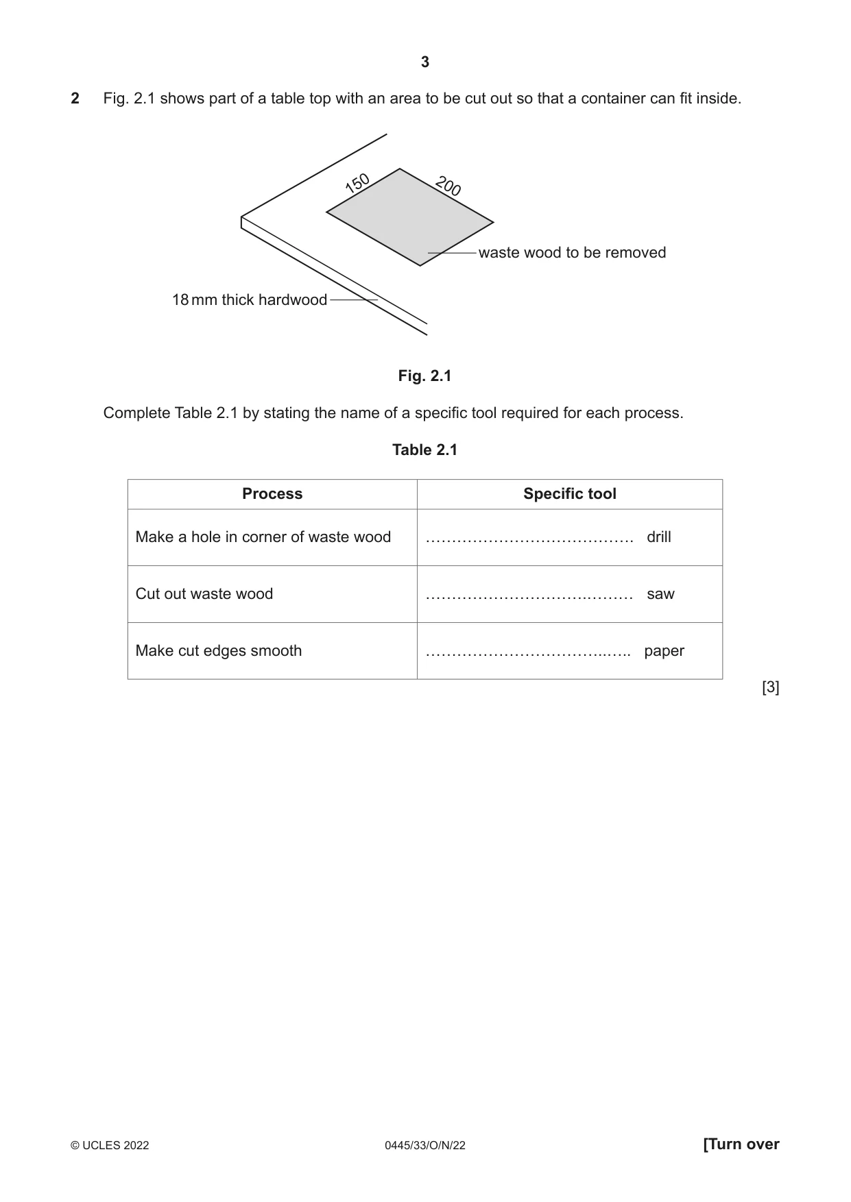
2 Fig. 2.1 shows part of a table top with an area to be cut out so that a container can fit inside. 150 200 waste wood to be removed 18 mm thick hardwood Fig. 2.1 Complete Table 2.1 by stating the name of a specific tool required for each process. Table 2.1 Process Specific tool Make a hole in corner of waste wood …………………………………. drill Cut out waste wood ………………………….……… saw Make cut edges smooth ……………………………..….. paper [3]
Mark scheme: 2 Twist drill, hole saw 1 3 Hegner, bow, pad, jig, scroll, coping saw 1 Glasspaper, sandpaper, aluminium oxide, garnet paper 1 Not wet and dry paper, abrasive paper
Q3 · A set of hardwood skittles that have been made using a woodturning lathe
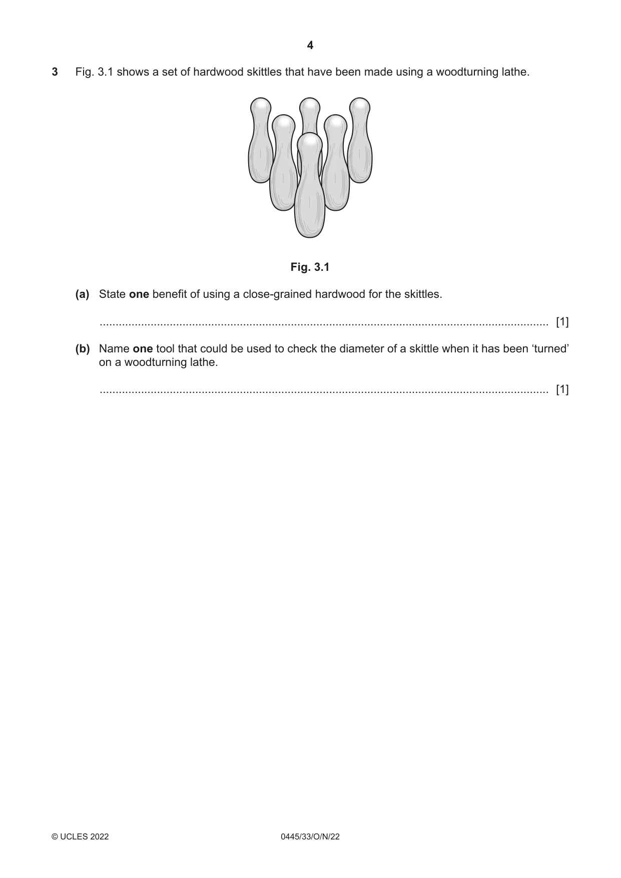
3 Fig. 3.1 shows a set of hardwood skittles that have been made using a woodturning lathe. Fig. 3.1 (a) State one benefit of using a close-grained hardwood for the skittles. ............................................................................................................................................. [1] (b) Name one tool that could be used to check the diameter of a skittle when it has been ‘turned’ on a woodturning lathe. ............................................................................................................................................. [1]
Mark scheme: 3(a) Benefit: wood is less likely to split/splinter when turned or in use, tough, dense 1 Not durable, hardwearing, strong 3(b) [Outside], [external] calipers, vernier 1 Not calipers, micrometer
Q4 · A cycle rack used in a public park
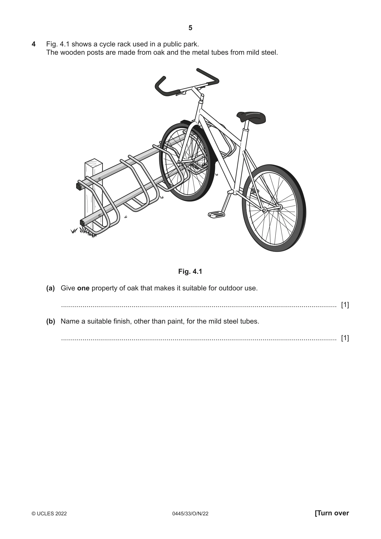
4 Fig. 4.1 shows a cycle rack used in a public park. The wooden posts are made from oak and the metal tubes from mild steel. Fig. 4.1 (a) Give one property of oak that makes it suitable for outdoor use. ............................................................................................................................................. [1] (b) Name a suitable finish, other than paint, for the mild steel tubes. ............................................................................................................................................. [1]
Mark scheme: 4(a) Hardwearing, weather resistant, long lasting, durable 1 4(b) Electroplated, galvanised 1 Not plastic coated
Question 5
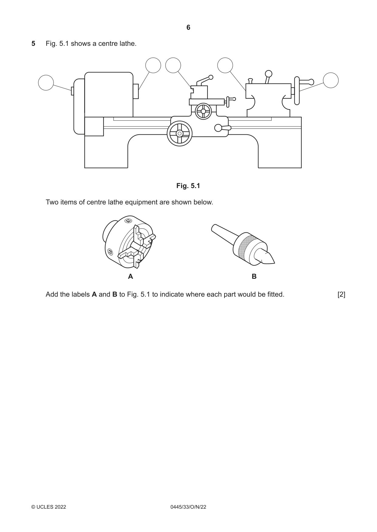
5 Fig. 5.1 shows a centre lathe. Fig. 5.1 Two items of centre lathe equipment are shown below. A B Add the labels A and B to Fig. 5.1 to indicate where each part would be fitted. [2]
Mark scheme: 5 A shown in headstock 1 2 Accept answers where the parts of the B shown in tailstock 1 lathe are drawn on the centre lathe
Q6 · An incomplete drawing of a mortise and tenon joint
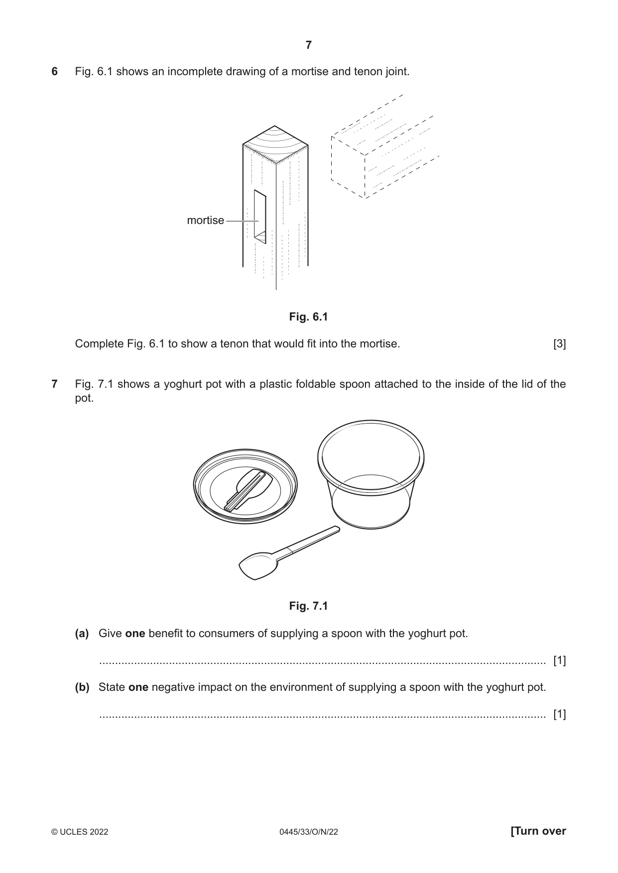
6 Fig. 6.1 shows an incomplete drawing of a mortise and tenon joint. mortise Fig. 6.1 Complete Fig. 6.1 to show a tenon that would fit into the mortise. [3]
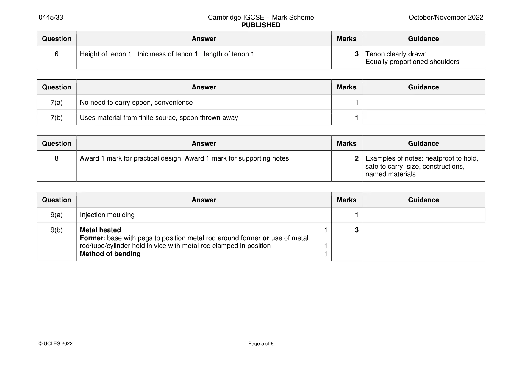
Mark scheme: 6 Height of tenon 1 thickness of tenon 1 length of tenon 1 3 Tenon clearly drawn Equally proportioned shoulders
Q7 · A yoghurt pot with a plastic foldable spoon attached to the inside of the lid of the pot
7 Fig. 7.1 shows a yoghurt pot with a plastic foldable spoon attached to the inside of the lid of the pot. Fig. 7.1 (a) Give one benefit to consumers of supplying a spoon with the yoghurt pot. ............................................................................................................................................. [1] (b) State one negative impact on the environment of supplying a spoon with the yoghurt pot. ............................................................................................................................................. [1]
Mark scheme: 7(a) No need to carry spoon, convenience 1 7(b) Uses material from finite source, spoon thrown away 1
Q8 · A barbecue made from 1.5 mm thick mild steel sheet
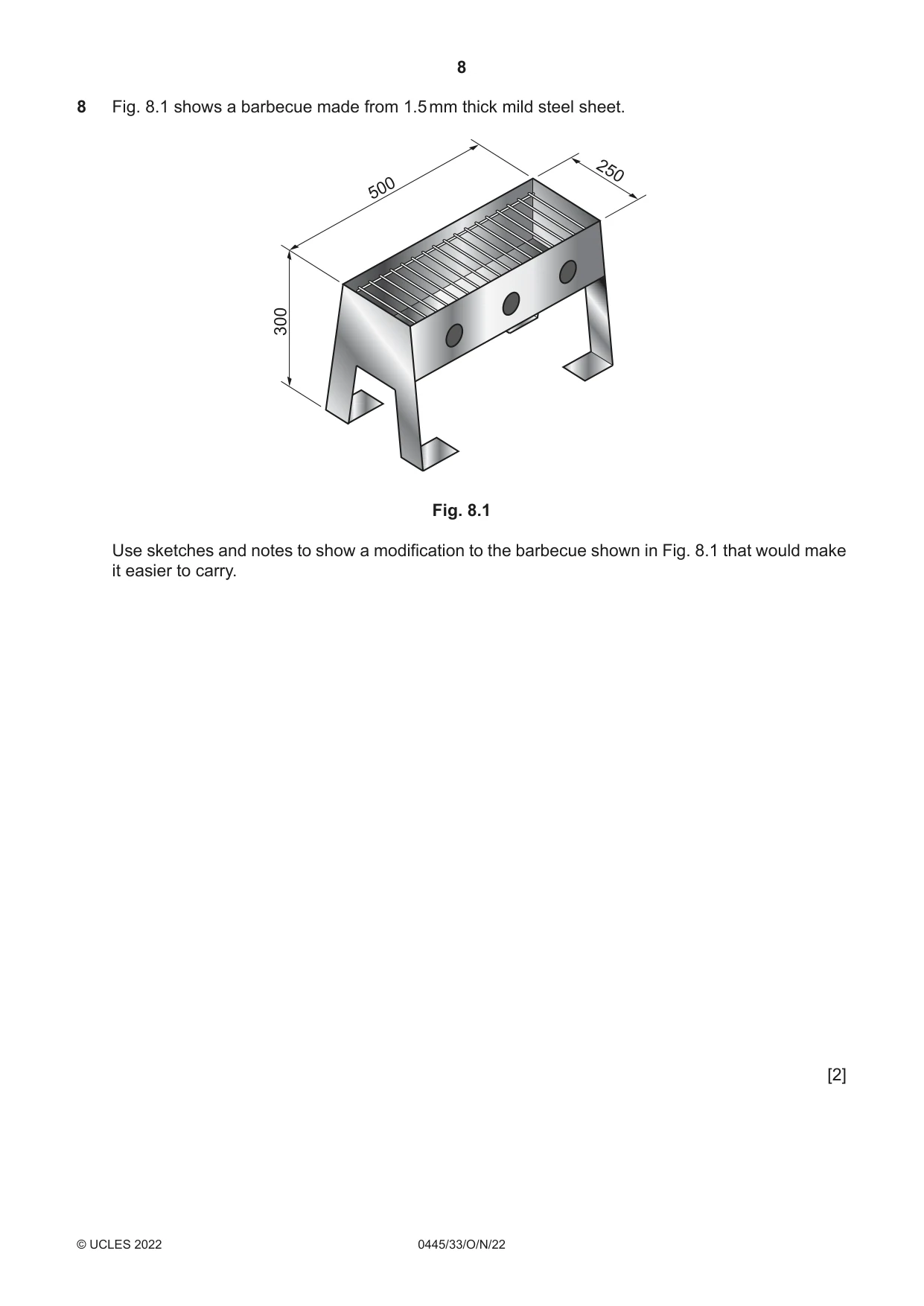
8 Fig. 8.1 shows a barbecue made from 1.5 mm thick mild steel sheet. 250 500 300 Fig. 8.1 Use sketches and notes to show a modification to the barbecue shown in Fig. 8.1 that would make it easier to carry. [2]
Mark scheme: 8 Award 1 mark for practical design. Award 1 mark for supporting notes 2 Examples of notes: heatproof to hold, safe to carry, size, constructions, named materials
Q9 · A child’s counting toy that could be made in a school workshop
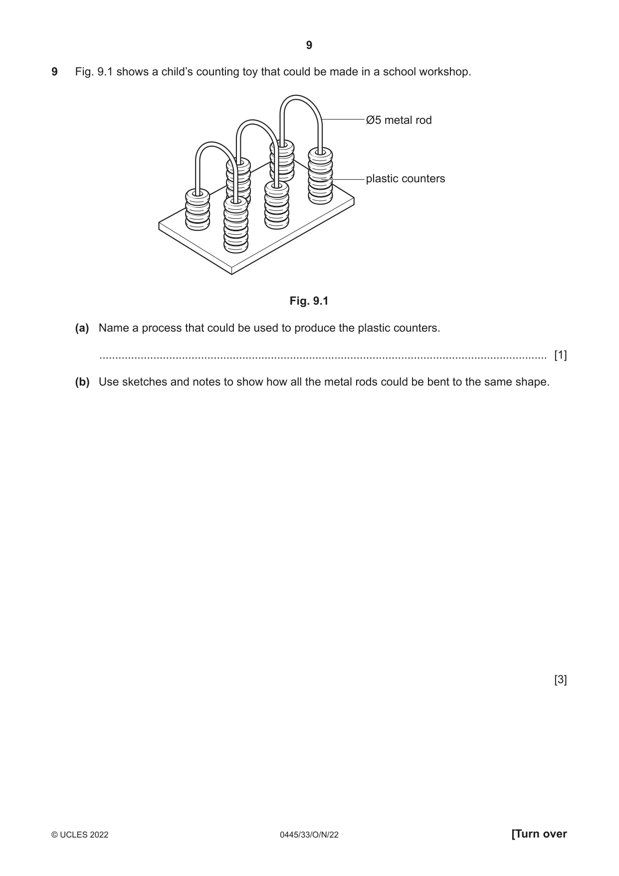
9 Fig. 9.1 shows a child’s counting toy that could be made in a school workshop. Ø5 metal rod plastic counters Fig. 9.1 (a) Name a process that could be used to produce the plastic counters. ............................................................................................................................................. [1] (b) Use sketches and notes to show how all the metal rods could be bent to the same shape. [3]
Mark scheme: 9(a) Injection moulding 1 9(b) Metal heated 1 3 Former: base with pegs to position metal rod around former or use of metal rod/tube/cylinder held in vice with metal rod clamped in position 1 Method of bending 1
Q10 · A picnic table made from recycled plastic
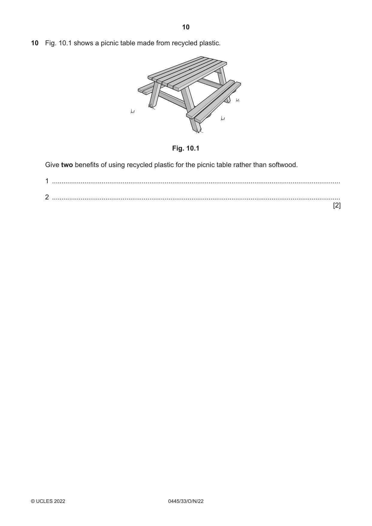
10 Fig. 10.1 shows a picnic table made from recycled plastic. Fig. 10.1 Give two benefits of using recycled plastic for the picnic table rather than softwood. 1 ....................................................................................................................................................... 2 ....................................................................................................................................................... [2]
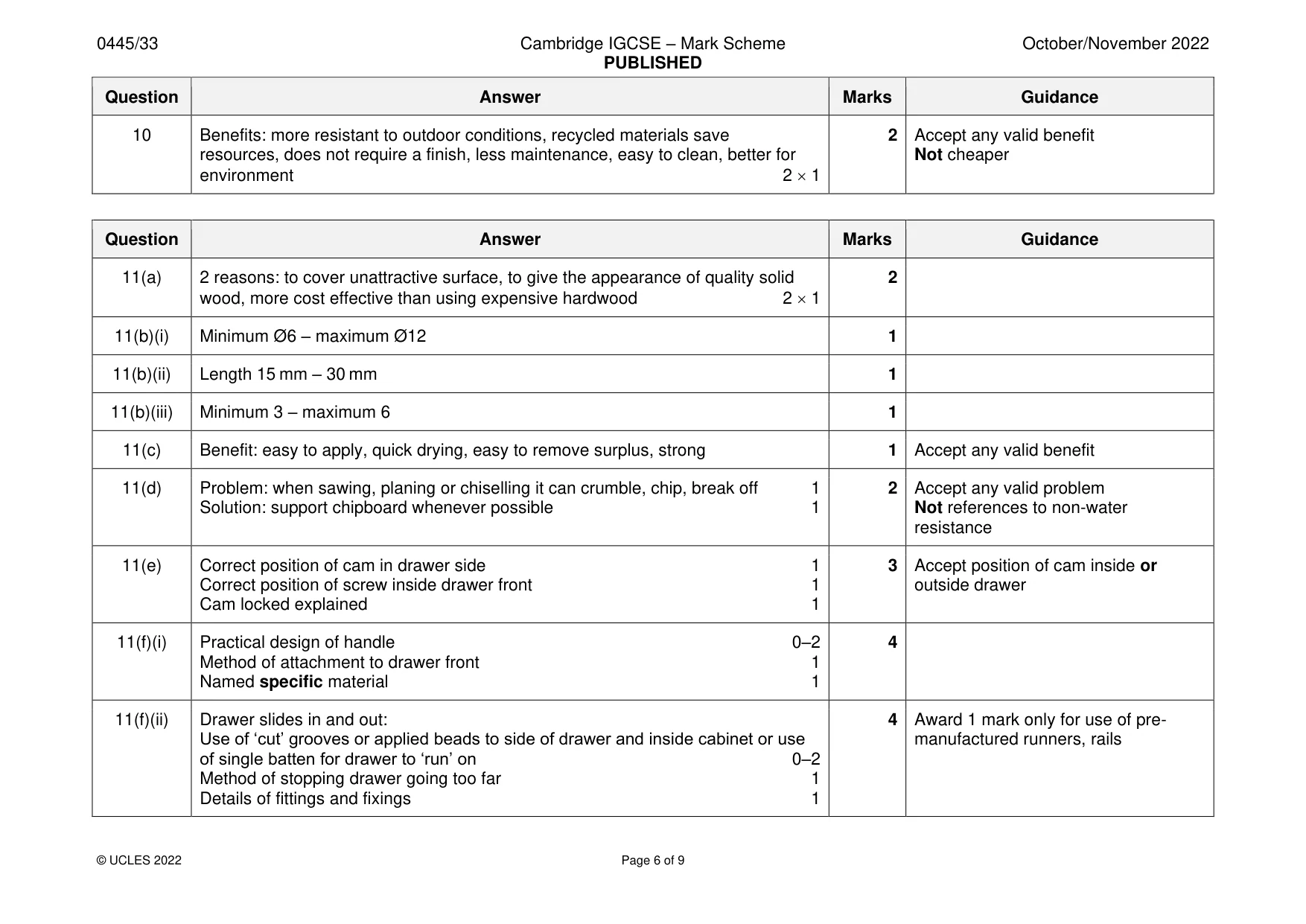
Mark scheme: 10 Benefits: more resistant to outdoor conditions, recycled materials save 2 Accept any valid benefit resources, does not require a finish, less maintenance, easy to clean, better for Not cheaper environment 2 1
Q11 · An incomplete design for a cabinet with a drawer
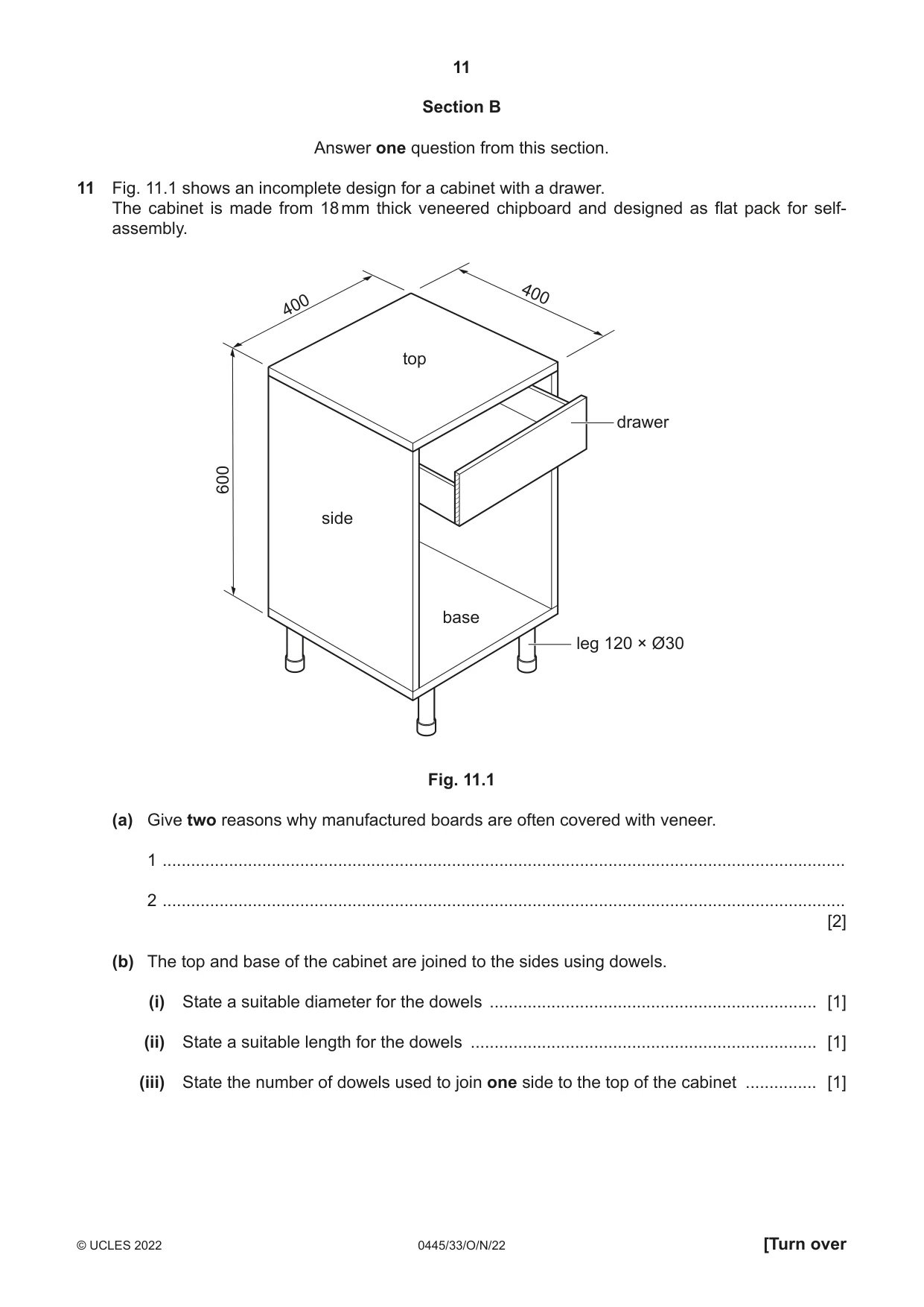
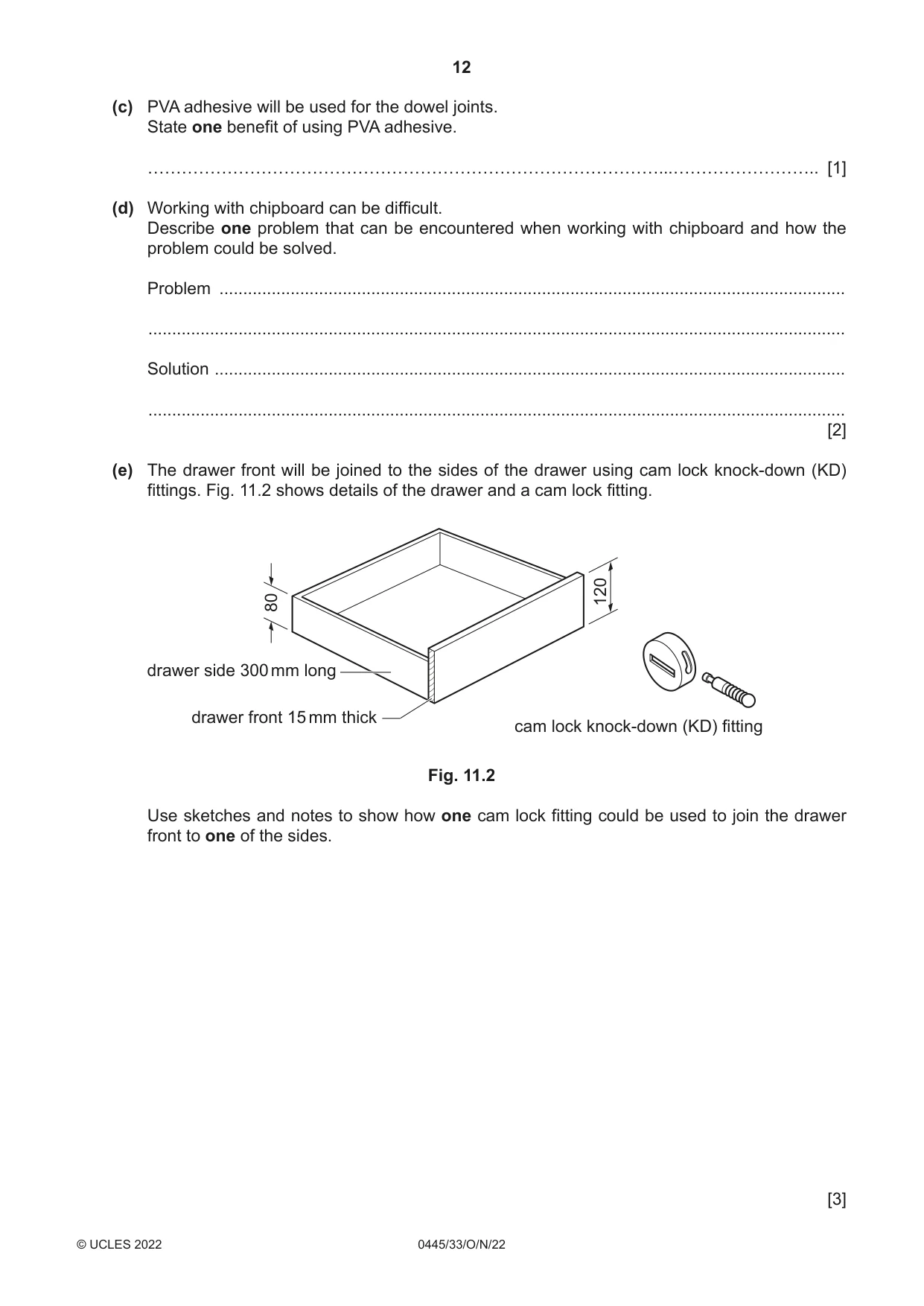
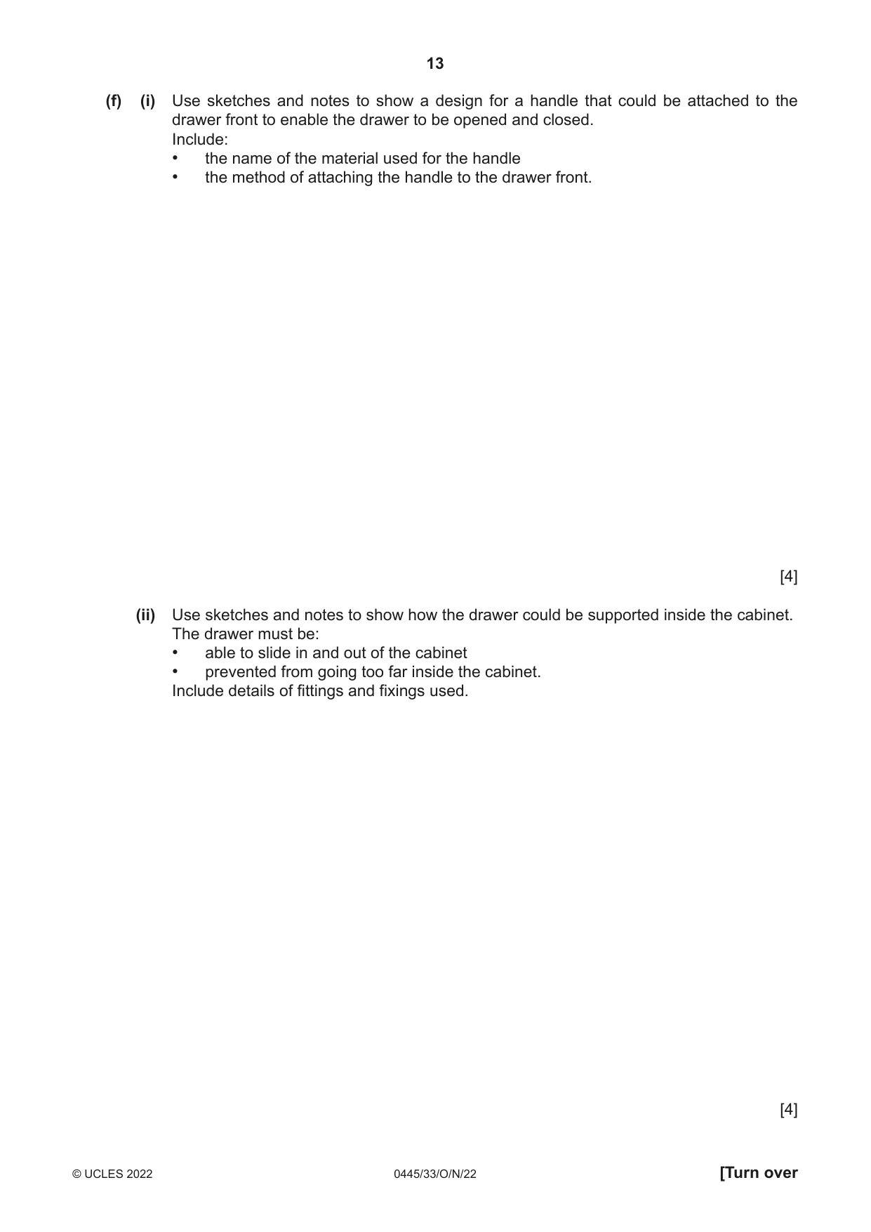
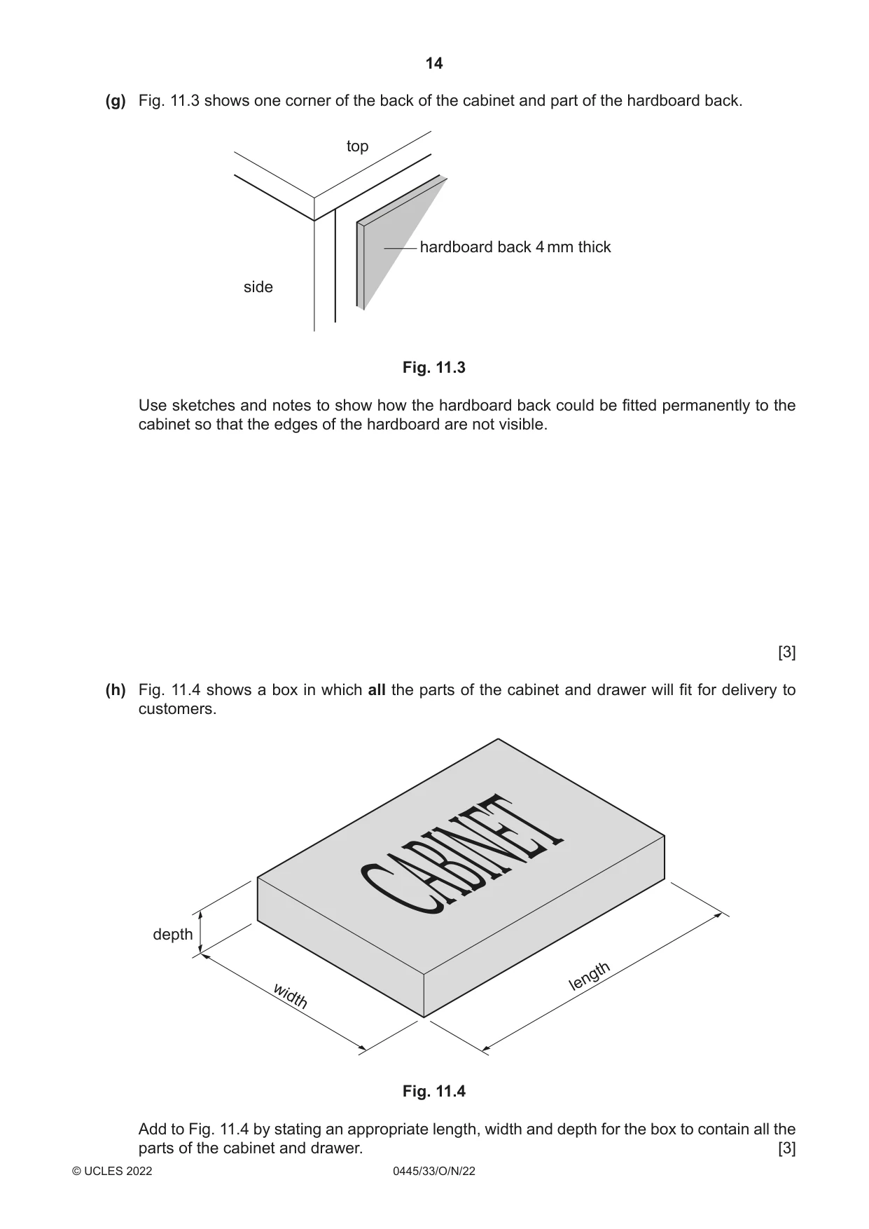
11 Fig. 11.1 shows an incomplete design for a cabinet with a drawer. The cabinet is made from 18 mm thick veneered chipboard and designed as flat pack for self- assembly. 400 400 top drawer 600 side base leg 120 × Ø30 Fig. 11.1 (a) Give two reasons why manufactured boards are often covered with veneer. 1 ................................................................................................................................................ 2 ................................................................................................................................................ [2] (b) The top and base of the cabinet are joined to the sides using dowels. (i) State a suitable diameter for the dowels ..................................................................... [1] (ii) State a suitable length for the dowels ......................................................................... [1] (iii) State the number of dowels used to join one side to the top of the cabinet ............... [1] (d) Working with chipboard can be difficult. Describe one problem that can be encountered when working with chipboard and how the problem could be solved. Problem .................................................................................................................................... ................................................................................................................................................... Solution ..................................................................................................................................... ................................................................................................................................................... [2] (e) The drawer front will be joined to the sides of the drawer using cam lock knock-down (KD) fittings. Fig. 11.2 shows details of the drawer and a cam lock fitting. 120 80 drawer side 300 mm long drawer front 15 mm thick cam lock knock-down (KD) fitting Fig. 11.2 Use sketches and notes to show how one cam lock fitting could be used to join the drawer front to one of the sides. [3] (f) (i) Use sketches and notes to show a design for a handle that could be attached to the drawer front to enable the drawer to be opened and closed. Include: • the name of the material used for the handle • the method of attaching the handle to the drawer front. [4] (ii) Use sketches and notes to show how the drawer could be supported inside the cabinet. The drawer must be: • able to slide in and out of the cabinet • prevented from going too far inside the cabinet. Include details of fittings and fixings used. [4] (g) Fig. 11.3 shows one corner of the back of the cabinet and part of the hardboard back. top hardboard back 4 mm thick side Fig. 11.3 Use sketches and notes to show how the hardboard back could be fitted permanently to the cabinet so that the edges of the hardboard are not visible. [3] (h) Fig. 11.4 shows a box in which all the parts of the cabinet and drawer will fit for delivery to customers. depth CABINET length width Fig. 11.4 Add to Fig. 11.4 by stating an appropriate length, width and depth for the box to contain all the parts of the cabinet and drawer. [3]
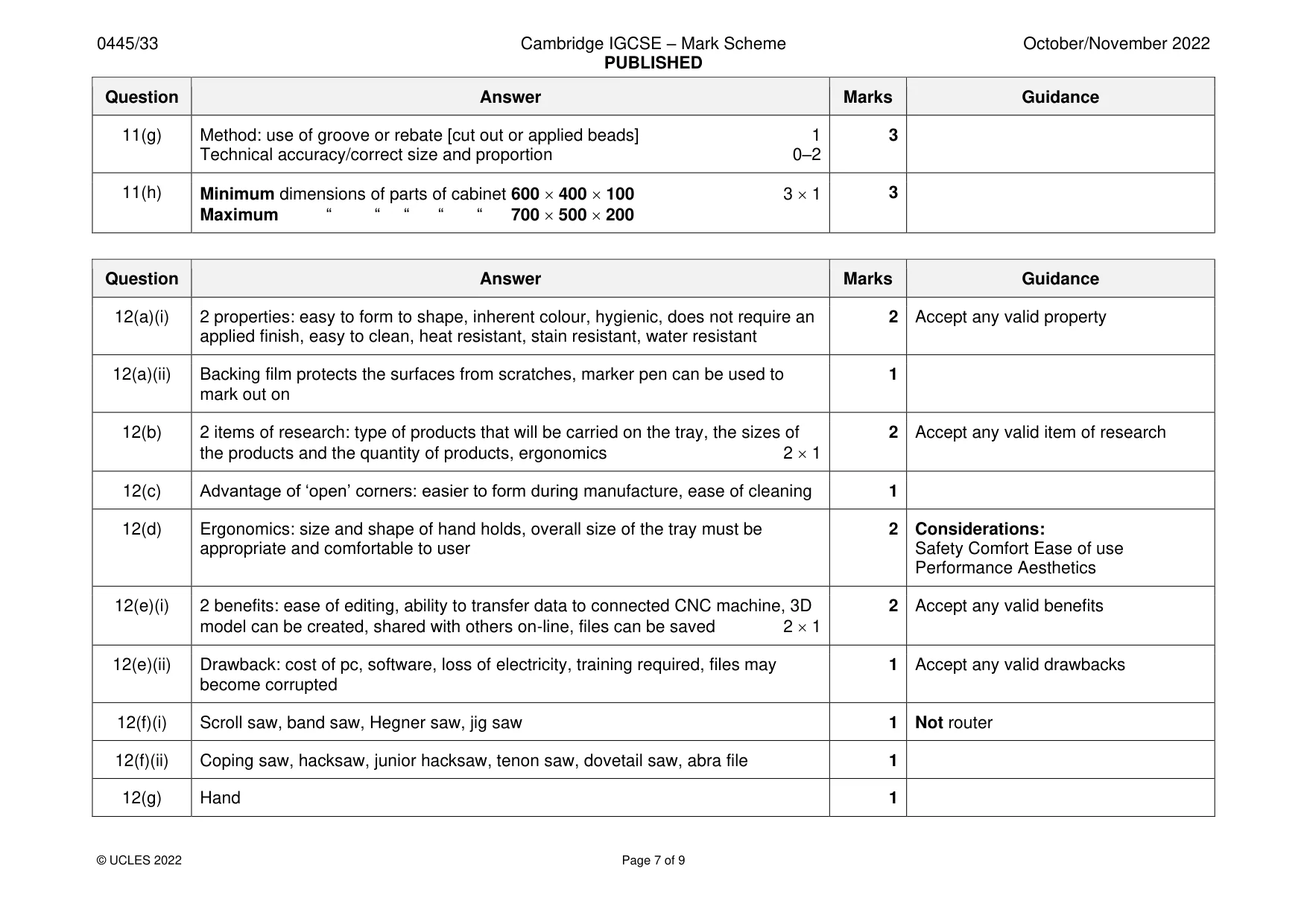
Mark scheme: 11(a) 2 reasons: to cover unattractive surface, to give the appearance of quality solid 2 wood, more cost effective than using expensive hardwood 2 1 11(b)(i) Minimum Ø6 – maximum Ø12 1 11(b)(ii) Length 15 mm – 30 mm 1 11(b)(iii) Minimum 3 – maximum 6 1 11(c) Benefit: easy to apply, quick drying, easy to remove surplus, strong 1 Accept any valid benefit 11(d) Problem: when sawing, planing or chiselling it can crumble, chip, break off 1 2 Accept any valid problem Solution: support chipboard whenever possible 1 Not references to non-water resistance 11(e) Correct position of cam in drawer side 1 3 Accept position of cam inside or Correct position of screw inside drawer front 1 outside drawer Cam locked explained 1 11(f)(i) Practical design of handle 0–2 4 Method of attachment to drawer front 1 Named specific material 1 11(f)(ii) Drawer slides in and out: 4 Award 1 mark only for use of pre- Use of ‘cut’ grooves or applied beads to side of drawer and inside cabinet or use manufactured runners, rails of single batten for drawer to ‘run’ on 0–2 Method of stopping drawer going too far 1 Details of fittings and fixings 1 11(g) Method: use of groove or rebate [cut out or applied beads] 1 3 Technical accuracy/correct size and proportion 0–2 11(h) Minimum dimensions of parts of cabinet 600 400 100 3 1 3 Maximum “ “ “ “ “ 700 500 200
Q12 · A tray made from 5 mm thick acrylic
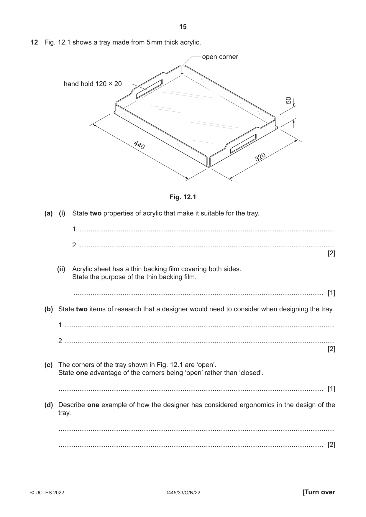
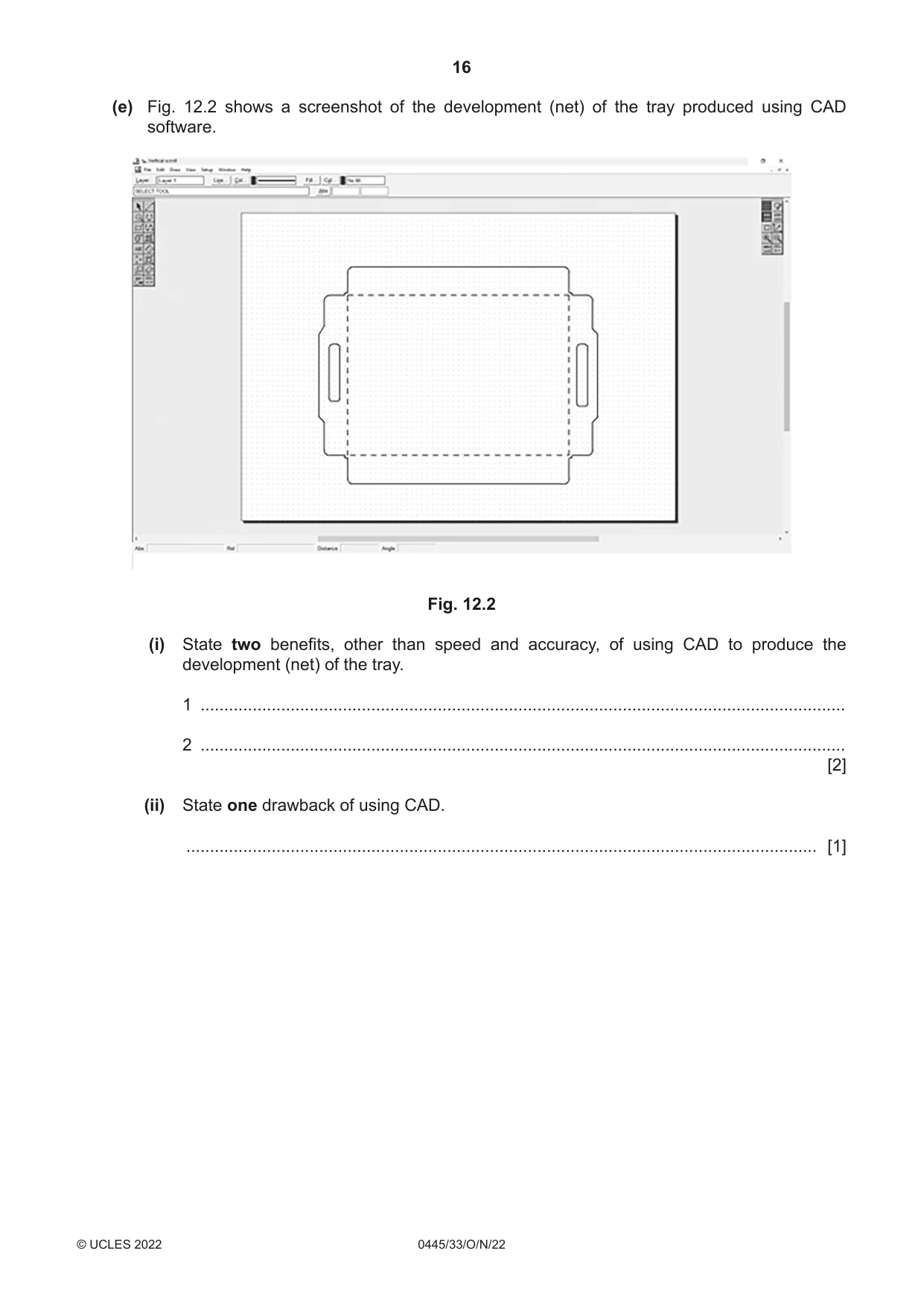
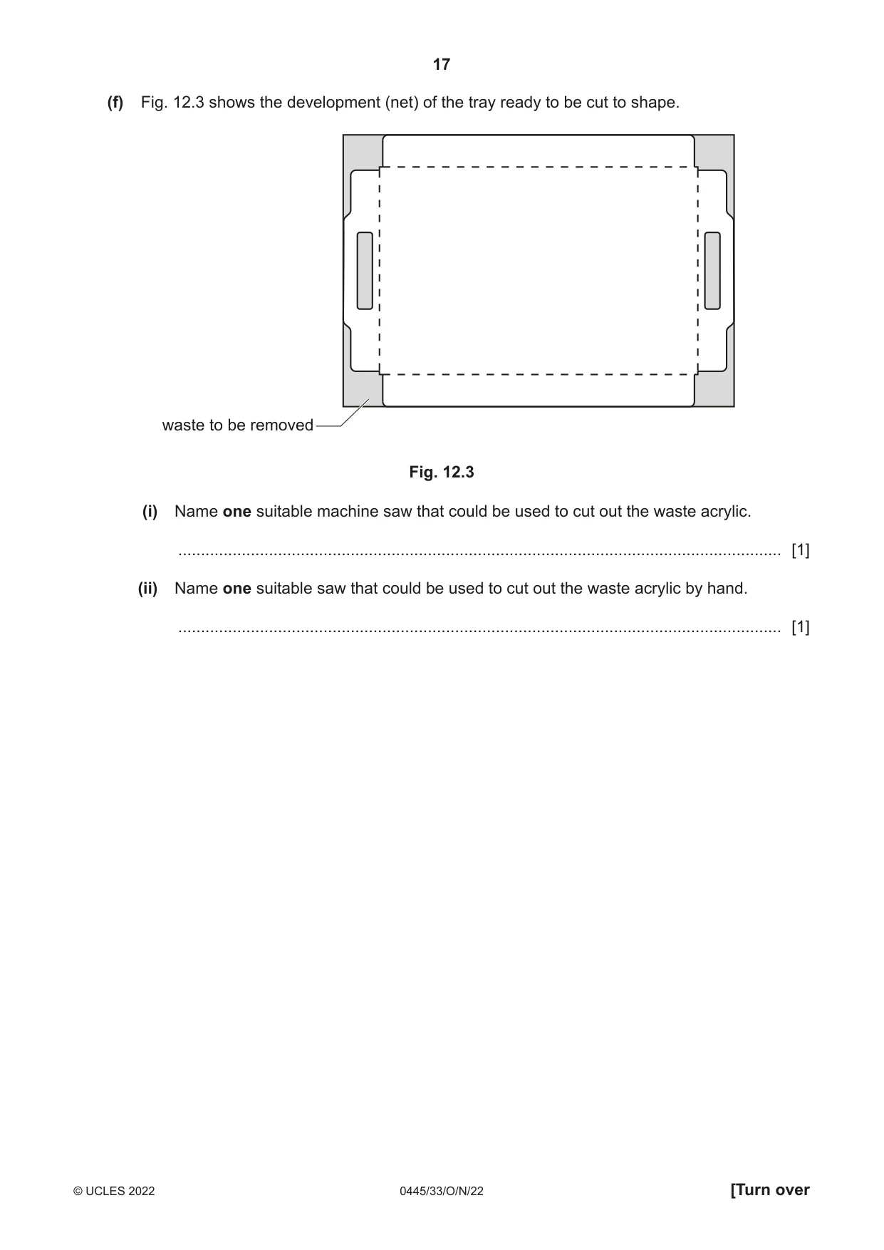
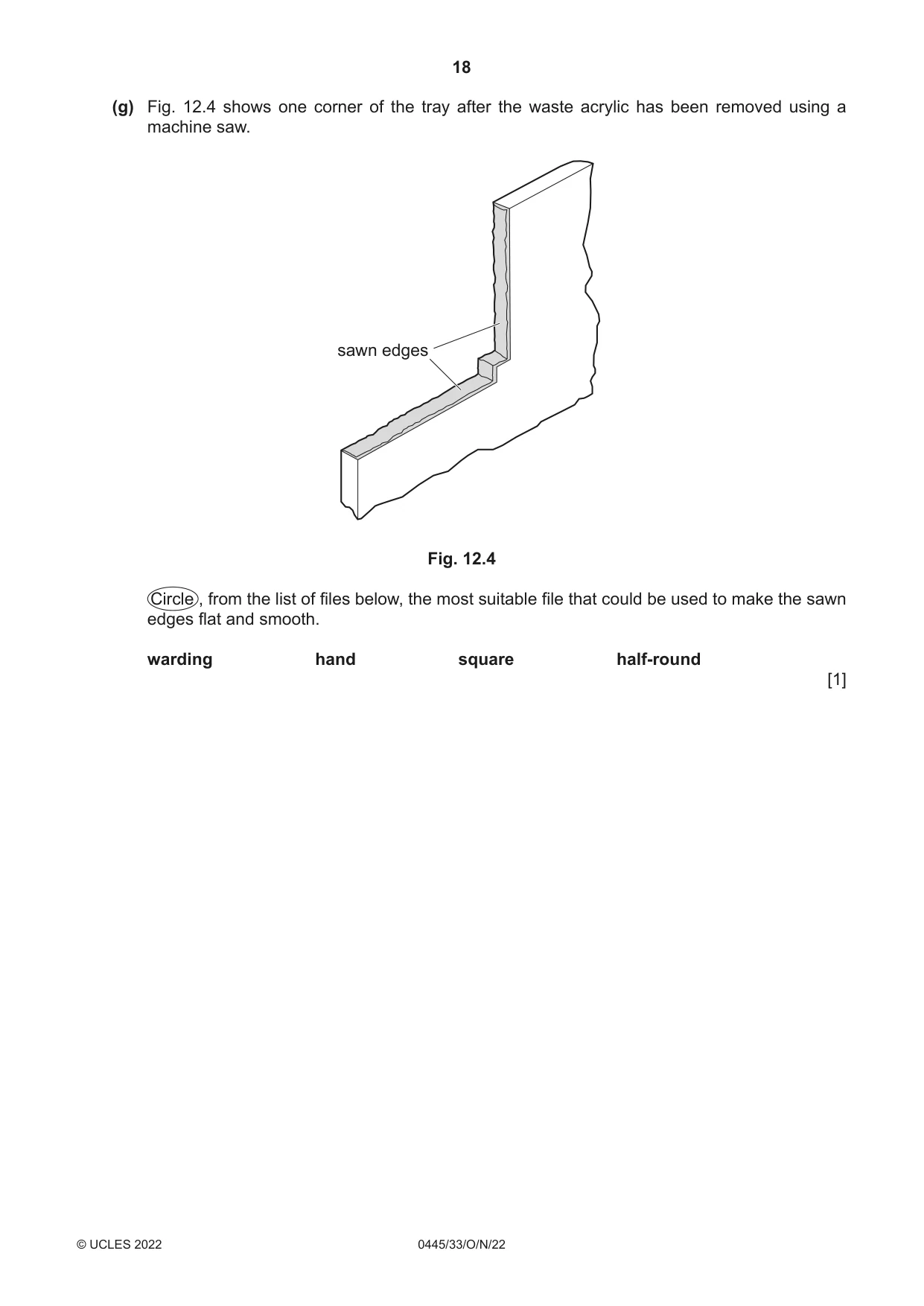
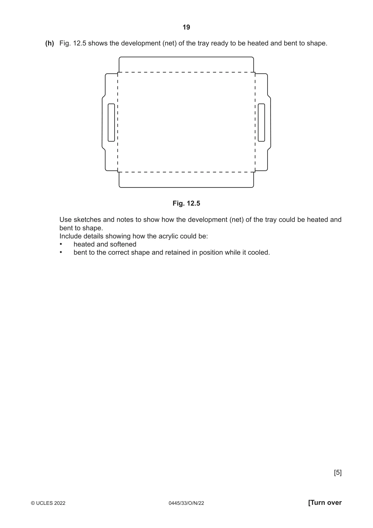
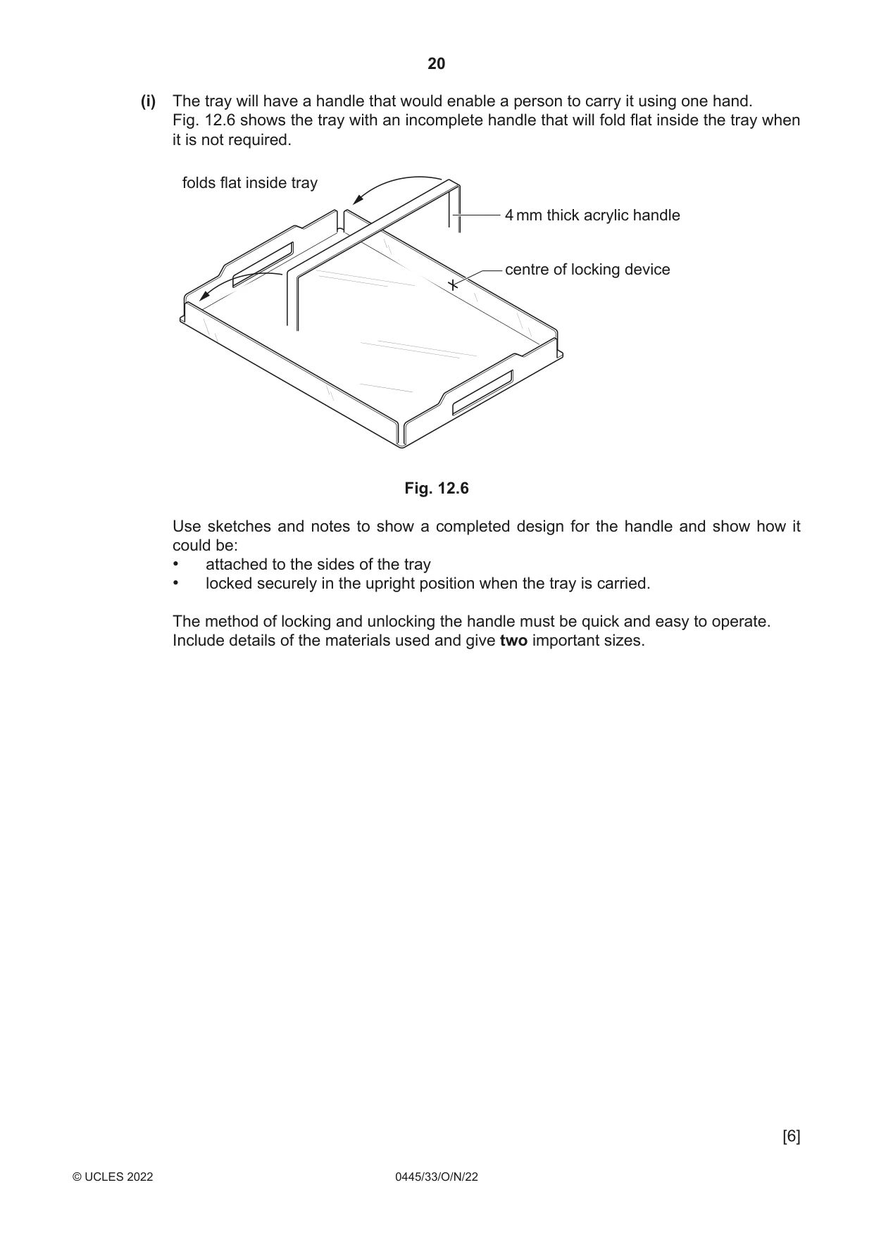
12 Fig. 12.1 shows a tray made from 5 mm thick acrylic. open corner hand hold 120 × 20 50 440 320 Fig. 12.1 (a) (i) State two properties of acrylic that make it suitable for the tray. 1 ........................................................................................................................................ 2 ........................................................................................................................................ [2] (ii) Acrylic sheet has a thin backing film covering both sides. State the purpose of the thin backing film. ..................................................................................................................................... [1] (b) State two items of research that a designer would need to consider when designing the tray. 1 ................................................................................................................................................ 2 ................................................................................................................................................ [2] (c) The corners of the tray shown in Fig. 12.1 are ‘open’. State one advantage of the corners being ‘open’ rather than ‘closed’. ............................................................................................................................................. [1] (d) Describe one example of how the designer has considered ergonomics in the design of the tray. ................................................................................................................................................... ............................................................................................................................................. [2] (e) Fig. 12.2 shows a screenshot of the development (net) of the tray produced using CAD software. Fig. 12.2 (i) State two benefits, other than speed and accuracy, of using CAD to produce the development (net) of the tray. 1 ........................................................................................................................................ 2 ........................................................................................................................................ [2] (ii) State one drawback of using CAD. ..................................................................................................................................... [1] (f) Fig. 12.3 shows the development (net) of the tray ready to be cut to shape. waste to be removed Fig. 12.3 (i) Name one suitable machine saw that could be used to cut out the waste acrylic. ..................................................................................................................................... [1] (ii) Name one suitable saw that could be used to cut out the waste acrylic by hand. ..................................................................................................................................... [1] (g) Fig. 12.4 shows one corner of the tray after the waste acrylic has been removed using a machine saw. sawn edges Fig. 12.4 Circle , from the list of files below, the most suitable file that could be used to make the sawn edges flat and smooth. warding hand square half-round [1] (h) Fig. 12.5 shows the development (net) of the tray ready to be heated and bent to shape. Fig. 12.5 Use sketches and notes to show how the development (net) of the tray could be heated and bent to shape. Include details showing how the acrylic could be: • heated and softened • bent to the correct shape and retained in position while it cooled. [5] (i) The tray will have a handle that would enable a person to carry it using one hand. Fig. 12.6 shows the tray with an incomplete handle that will fold flat inside the tray when it is not required. folds flat inside tray 4 mm thick acrylic handle centre of locking device Fig. 12.6 Use sketches and notes to show a completed design for the handle and show how it could be: • attached to the sides of the tray • locked securely in the upright position when the tray is carried. The method of locking and unlocking the handle must be quick and easy to operate. Include details of the materials used and give two important sizes. [6]
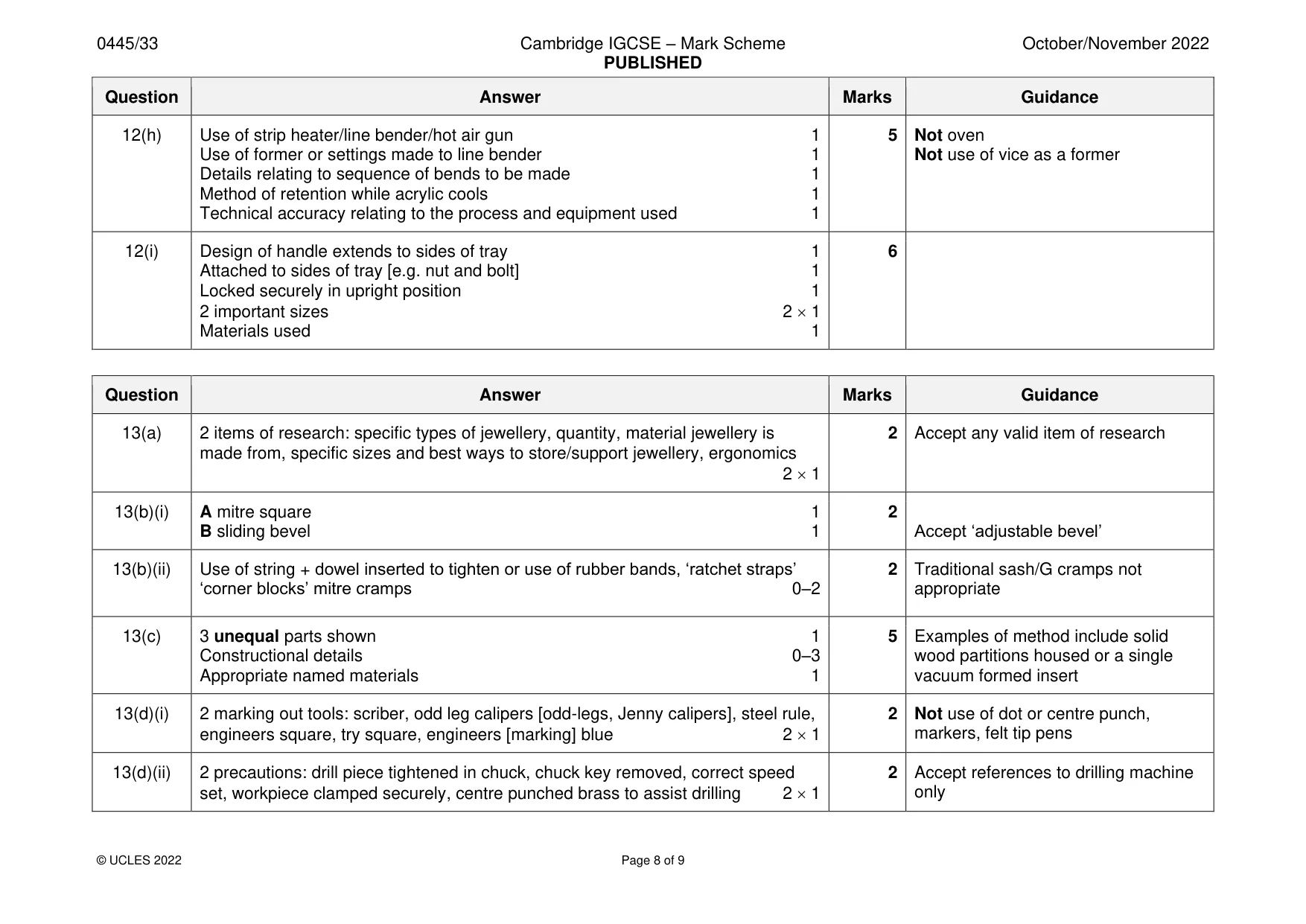
Mark scheme: 12(a)(i) 2 properties: easy to form to shape, inherent colour, hygienic, does not require an 2 Accept any valid property applied finish, easy to clean, heat resistant, stain resistant, water resistant 12(a)(ii) Backing film protects the surfaces from scratches, marker pen can be used to 1 mark out on 12(b) 2 items of research: type of products that will be carried on the tray, the sizes of 2 Accept any valid item of research the products and the quantity of products, ergonomics 2 1 12(c) Advantage of ‘open’ corners: easier to form during manufacture, ease of cleaning 1 12(d) Ergonomics: size and shape of hand holds, overall size of the tray must be 2 Considerations: appropriate and comfortable to user Safety Comfort Ease of use Performance Aesthetics 12(e)(i) 2 benefits: ease of editing, ability to transfer data to connected CNC machine, 3D 2 Accept any valid benefits model can be created, shared with others on-line, files can be saved 2 1 12(e)(ii) Drawback: cost of pc, software, loss of electricity, training required, files may 1 Accept any valid drawbacks become corrupted 12(f)(i) Scroll saw, band saw, Hegner saw, jig saw 1 Not router 12(f)(ii) Coping saw, hacksaw, junior hacksaw, tenon saw, dovetail saw, abra file 1 12(g) Hand 1 12(h) Use of strip heater/line bender/hot air gun 1 5 Not oven Use of former or settings made to line bender 1 Not use of vice as a former Details relating to sequence of bends to be made 1 Method of retention while acrylic cools 1 Technical accuracy relating to the process and equipment used 1 12(i) Design of handle extends to sides of tray 1 6 Attached to sides of tray [e.g. nut and bolt] 1 Locked securely in upright position 1 2 important sizes 2 1 Materials used 1
Q13 · A jewellery stand made in a school workshop
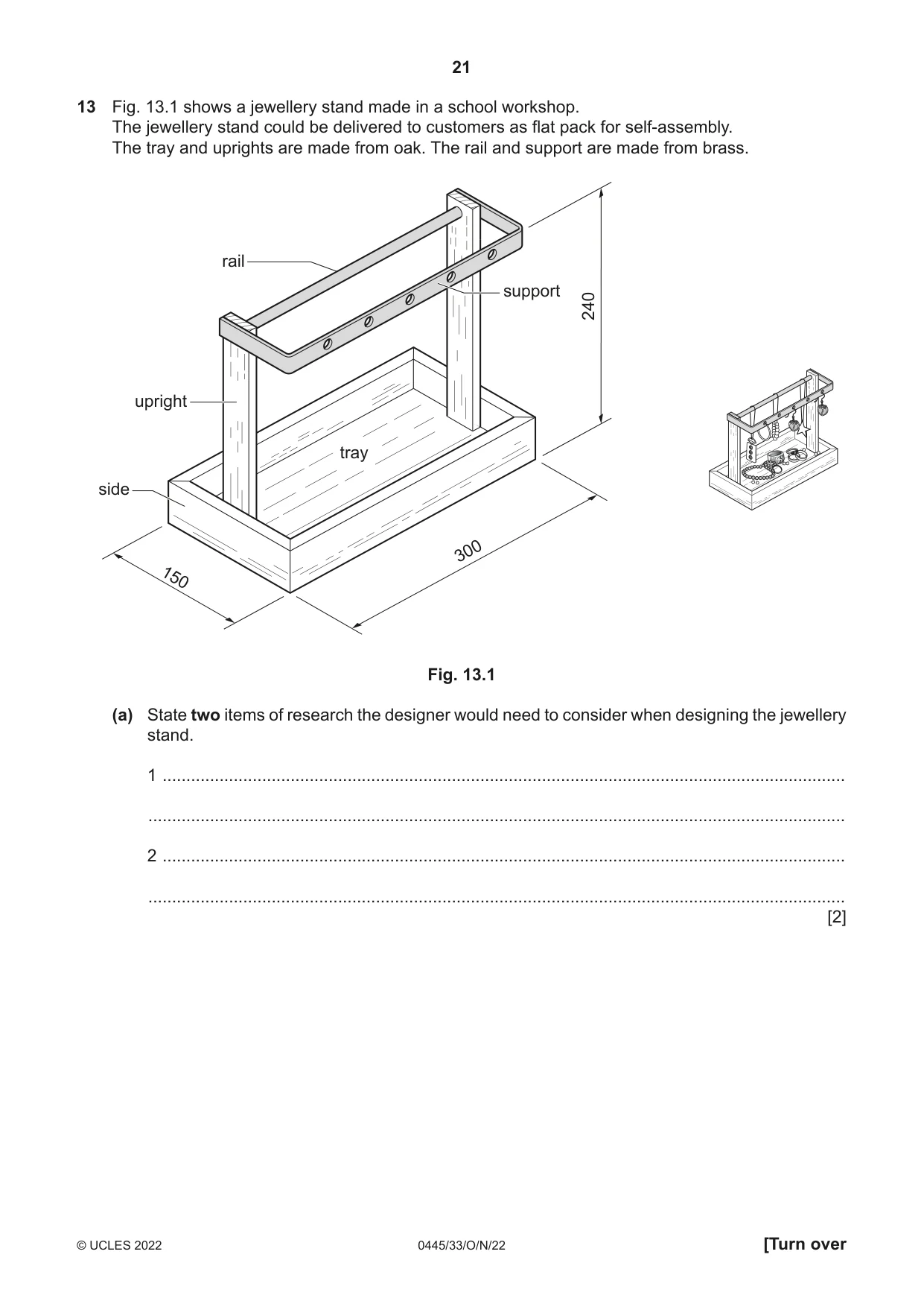
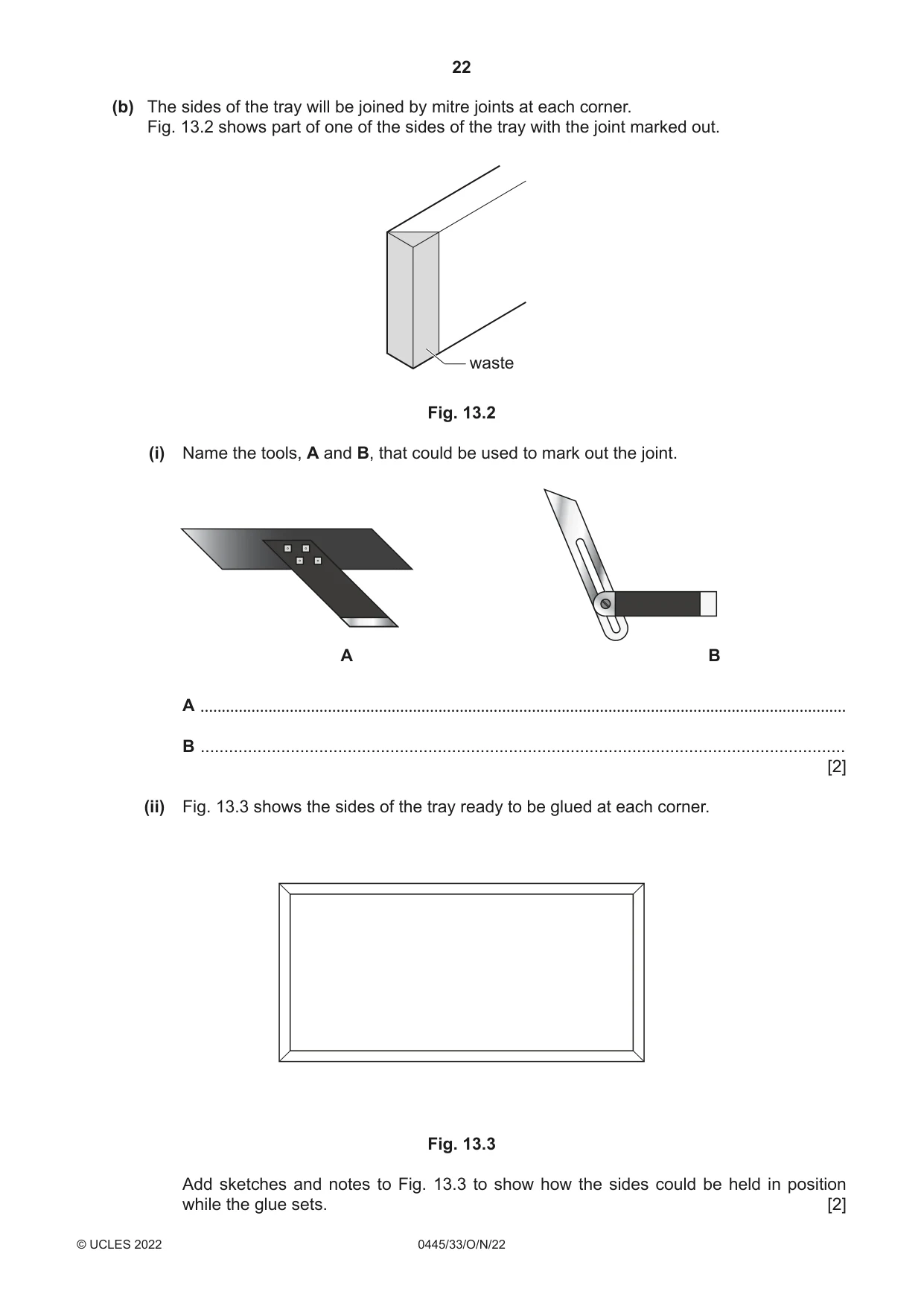
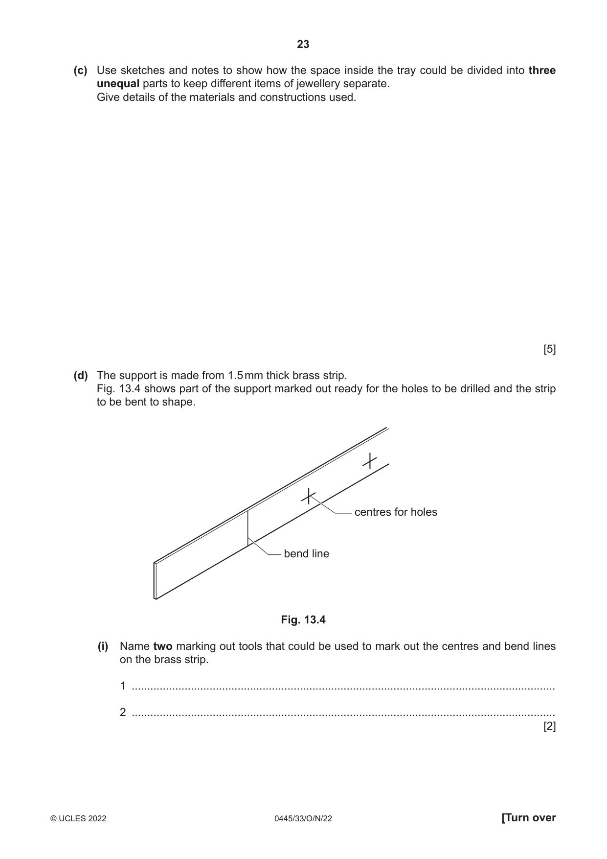
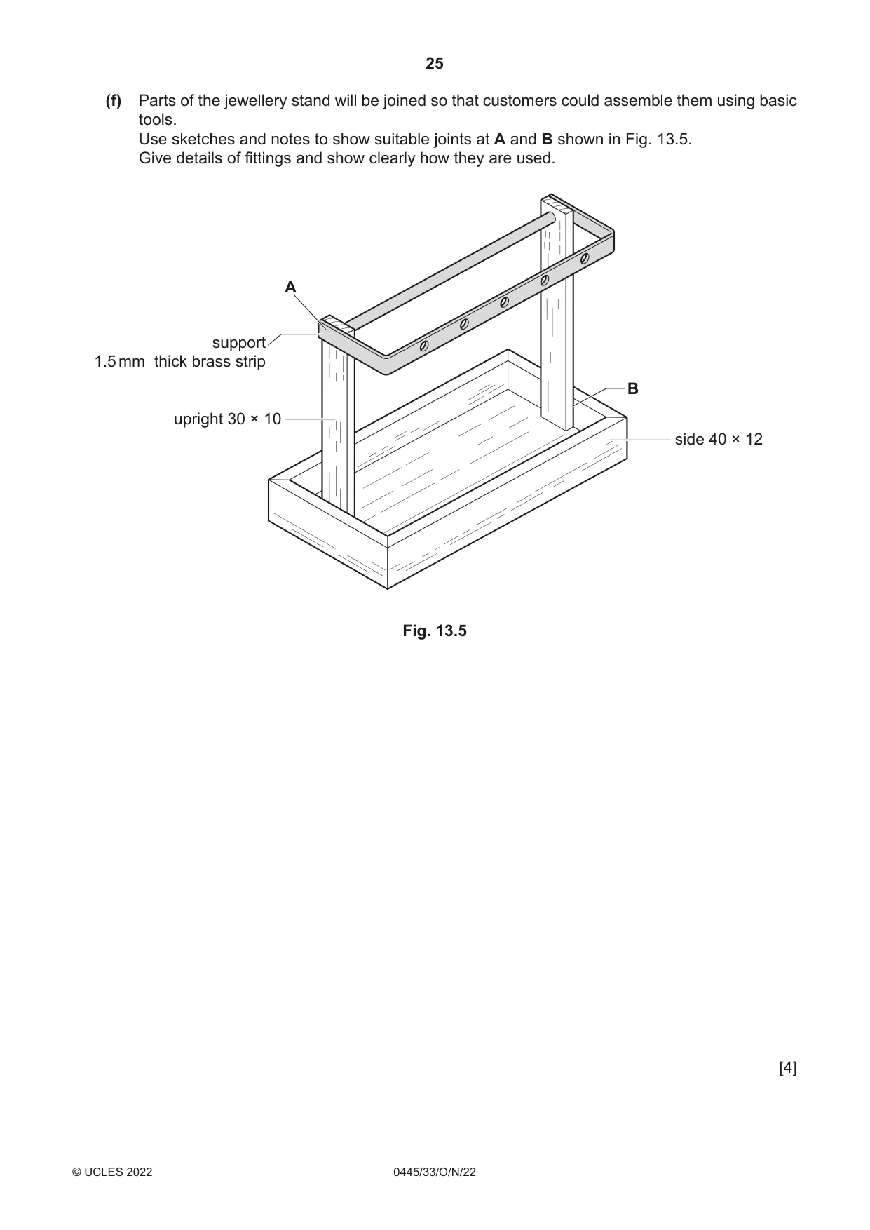
13 Fig. 13.1 shows a jewellery stand made in a school workshop. The jewellery stand could be delivered to customers as flat pack for self-assembly. The tray and uprights are made from oak. The rail and support are made from brass. rail support 240 upright tray side 300 150 Fig. 13.1 (a) State two items of research the designer would need to consider when designing the jewellery stand. 1 ................................................................................................................................................ ................................................................................................................................................... 2 ................................................................................................................................................ ................................................................................................................................................... [2] (b) The sides of the tray will be joined by mitre joints at each corner. Fig. 13.2 shows part of one of the sides of the tray with the joint marked out. waste Fig. 13.2 (i) Name the tools, A and B, that could be used to mark out the joint. A B A ........................................................................................................................................................ B ........................................................................................................................................ [2] (ii) Fig. 13.3 shows the sides of the tray ready to be glued at each corner. Fig. 13.3 Add sketches and notes to Fig. 13.3 to show how the sides could be held in position while the glue sets. [2] (c) Use sketches and notes to show how the space inside the tray could be divided into three unequal parts to keep different items of jewellery separate. Give details of the materials and constructions used. [5] (d) The support is made from 1.5 mm thick brass strip. Fig. 13.4 shows part of the support marked out ready for the holes to be drilled and the strip to be bent to shape. centres for holes bend line Fig. 13.4 (i) Name two marking out tools that could be used to mark out the centres and bend lines on the brass strip. 1 ........................................................................................................................................ 2 ........................................................................................................................................ [2]
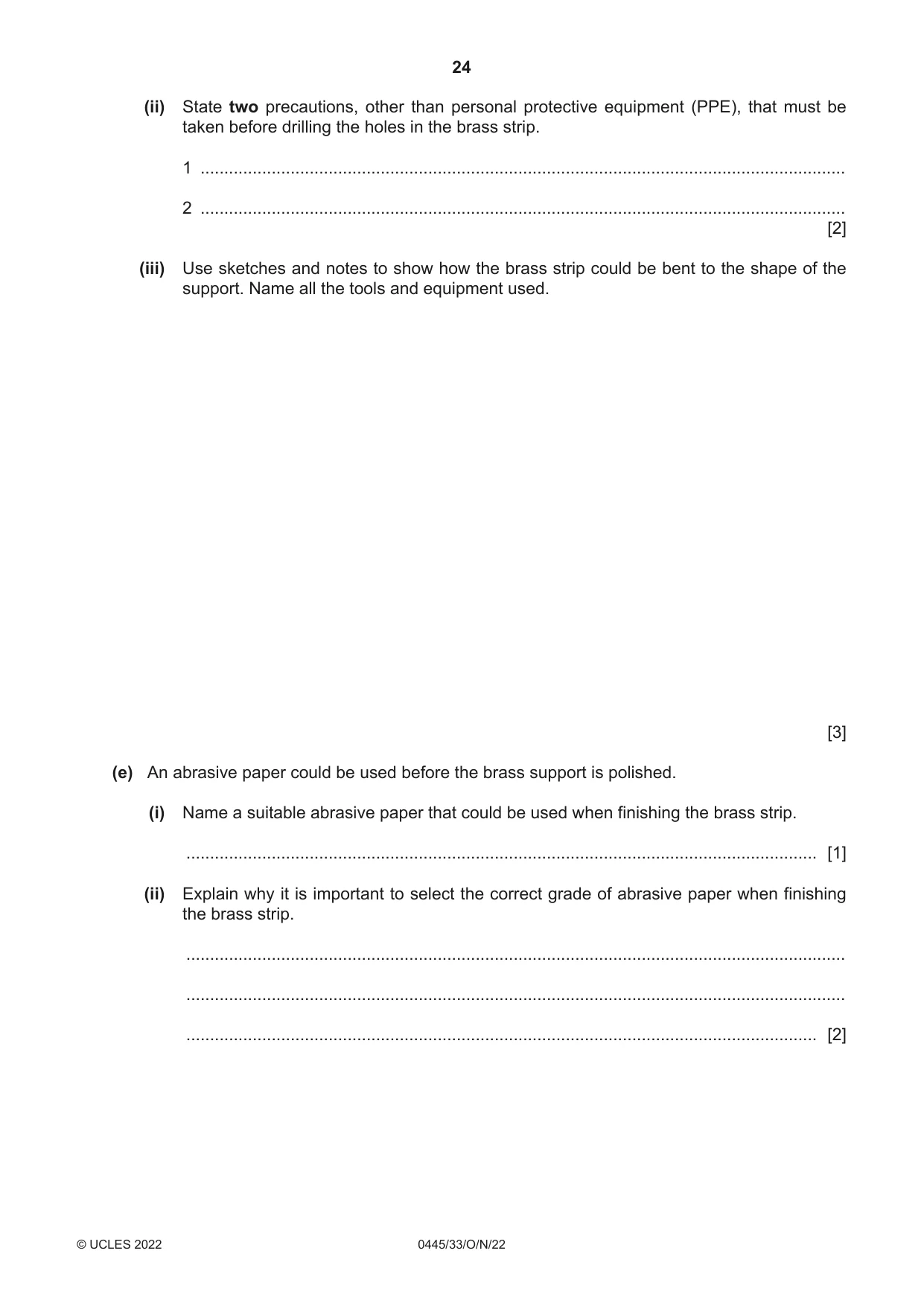
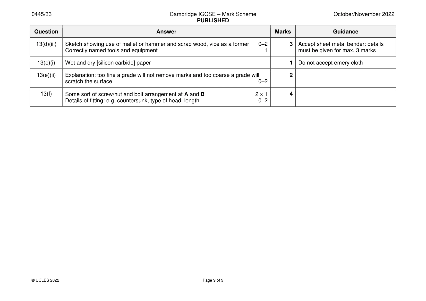
Mark scheme: 13(a) 2 items of research: specific types of jewellery, quantity, material jewellery is 2 Accept any valid item of research made from, specific sizes and best ways to store/support jewellery, ergonomics 2 1 13(b)(i) A mitre square 1 2 B sliding bevel 1 Accept ‘adjustable bevel’ 13(b)(ii) Use of string + dowel inserted to tighten or use of rubber bands, ‘ratchet straps’ 2 Traditional sash/G cramps not ‘corner blocks’ mitre cramps 0–2 appropriate 13(c) 3 unequal parts shown 1 5 Examples of method include solid Constructional details 0–3 wood partitions housed or a single Appropriate named materials 1 vacuum formed insert 13(d)(i) 2 marking out tools: scriber, odd leg calipers [odd-legs, Jenny calipers], steel rule, 2 Not use of dot or centre punch, engineers square, try square, engineers [marking] blue 2 1 markers, felt tip pens 13(d)(ii) 2 precautions: drill piece tightened in chuck, chuck key removed, correct speed 2 Accept references to drilling machine set, workpiece clamped securely, centre punched brass to assist drilling 2 1 only 13(d)(iii) Sketch showing use of mallet or hammer and scrap wood, vice as a former 0–2 3 Accept sheet metal bender: details Correctly named tools and equipment 1 must be given for max. 3 marks 13(e)(i) Wet and dry [silicon carbide] paper 1 Do not accept emery cloth 13(e)(ii) Explanation: too fine a grade will not remove marks and too coarse a grade will 2 scratch the surface 0–2 13(f) Some sort of screw/nut and bolt arrangement at A and B 2 1 4 Details of fitting: e.g. countersunk, type of head, length 0–2
What was in this paper
The subtopics covered by these 13 questions, and how many questions each got. Open one in a new tab to see every Cambridge question on it.
What you needed in this session
Cambridge’s own grade thresholds for 2022 Oct/Nov, Paper 3 · Variant 3. A higher threshold means an easier paper — the bar moves with how the cohort did.