Cambridge IGCSE Design and Technology 0445 — 2021 Oct/Nov Paper 3 · Variant 2
0445/32/O/N/21 · 13 questions · 50 marks · ≈56 min
The question paper and its mark scheme, free to read here and free to download. This is Cambridge’s own paper, exactly as it was sat.
Question paper20 pages
Mark scheme10 pages
Answers below. Sit the paper first if you are practising.
Questions as text
Q1 · Safety precautions need to be taken when carrying out different processes in a workshop
1 Safety precautions need to be taken when carrying out different processes in a workshop. Complete Table 1.1 by stating one safety precaution that would need to be taken for each process. Table 1.1 Process Safety precaution taken Using a pillar drill to drill sheet metal Using a disc sander to sand a hardwood block [2]
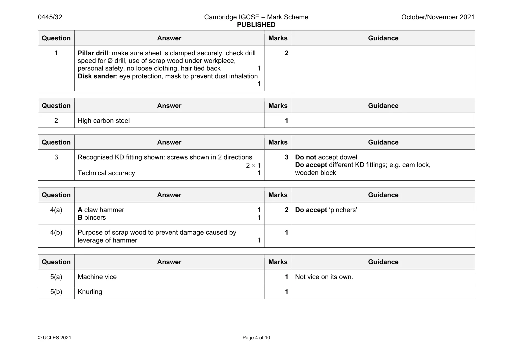
Mark scheme: 1 Pillar drill: make sure sheet is clamped securely, check drill speed for Ø drill, use of scrap wood under workpiece, personal safety, no loose clothing, hair tied back 1 Disk sander: eye protection, mask to prevent dust inhalation 1 2
Q2 · Circle from the list of materials below one metal that can be hardened
2 Circle from the list of materials below one metal that can be hardened. lead zinc high carbon steel cast iron [1]
Mark scheme: 2 High carbon steel 1
Q3 · Two pieces of hardwood that are to be joined by means of a KD (Knock-Down) fitting
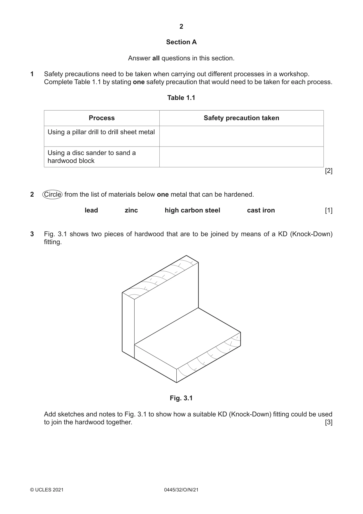
3 Fig. 3.1 shows two pieces of hardwood that are to be joined by means of a KD (Knock-Down) fitting. Fig. 3.1 Add sketches and notes to Fig. 3.1 to show how a suitable KD (Knock-Down) fitting could be used to join the hardwood together. [3]
Mark scheme: 3 Recognised KD fitting shown: screws shown in 2 directions 2 × 1 Technical accuracy 1 Do accept different KD fittings; e.g. cam lock, wooden block
Q4 · Two tools, A and B, that are used to remove nails from wood
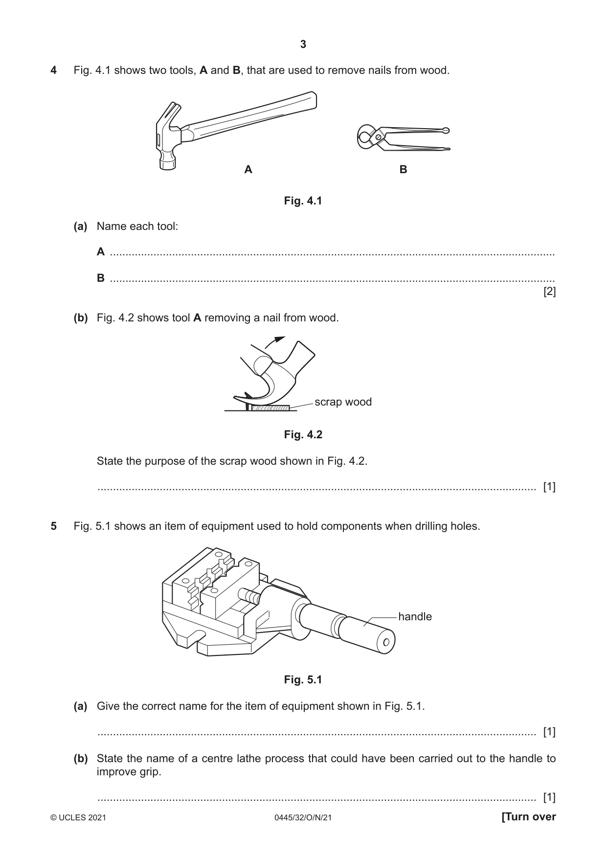
4 Fig. 4.1 shows two tools, A and B, that are used to remove nails from wood. A B Fig. 4.1 (a) Name each tool: A ............................................................................................................................................... B ............................................................................................................................................... [2] (b) Fig. 4.2 shows tool A removing a nail from wood. scrap wood Fig. 4.2 State the purpose of the scrap wood shown in Fig. 4.2. ............................................................................................................................................. [1]
Mark scheme: 4(a) A claw hammer 1 B pincers 1 2 Do accept ‘pinchers’ 4(b) Purpose of scrap wood to prevent damage caused by leverage of hammer 1 1
Q5 · An item of equipment used to hold components when drilling holes
5 Fig. 5.1 shows an item of equipment used to hold components when drilling holes. handle Fig. 5.1 (a) Give the correct name for the item of equipment shown in Fig. 5.1. ............................................................................................................................................. [1] (b) State the name of a centre lathe process that could have been carried out to the handle to improve grip. ............................................................................................................................................. [1]
Mark scheme: 5(a) Machine vice 1 Not vice on its own. 5(b) Knurling 1
Question 6
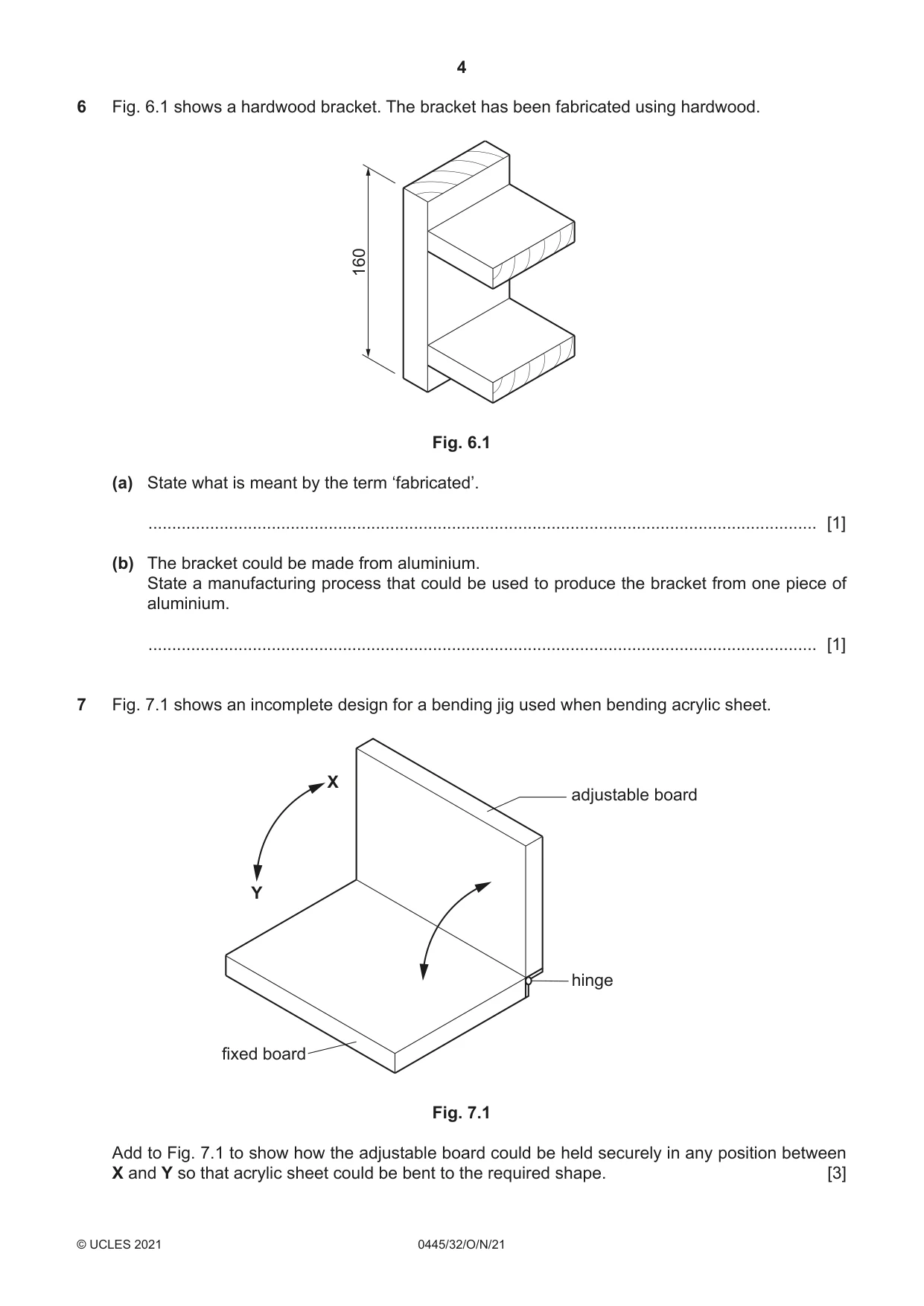
6 Fig. 6.1 shows a hardwood bracket. The bracket has been fabricated using hardwood. 160 Fig. 6.1 (a) State what is meant by the term ‘fabricated’. ............................................................................................................................................. [1] (b) The bracket could be made from aluminium. State a manufacturing process that could be used to produce the bracket from one piece of aluminium. ............................................................................................................................................. [1]
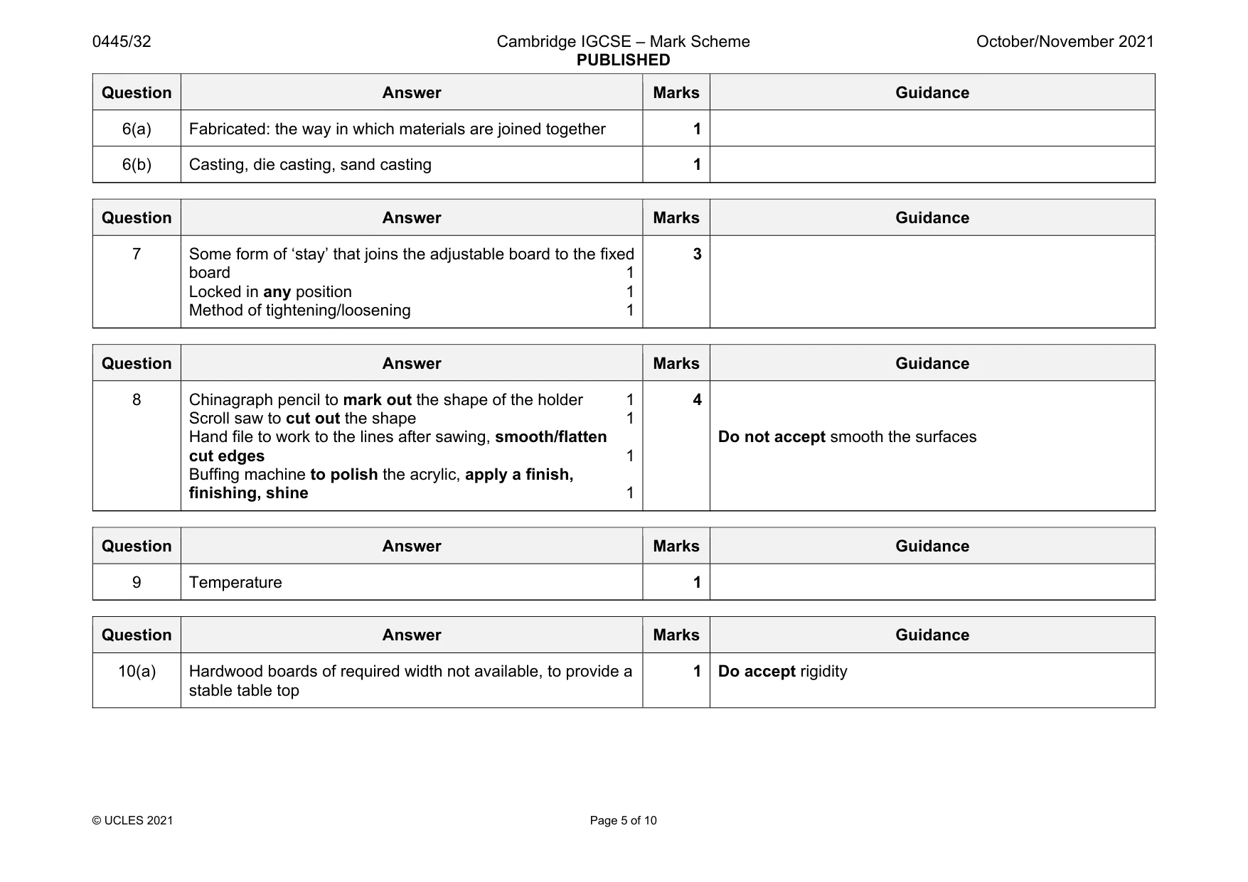
Mark scheme: 6(a) Fabricated: the way in which materials are joined together 1 6(b) Casting, die casting, sand casting 1
Q7 · An incomplete design for a bending jig used when bending acrylic sheet
7 Fig. 7.1 shows an incomplete design for a bending jig used when bending acrylic sheet. X adjustable board Y hinge fixed board Fig. 7.1 Add to Fig. 7.1 to show how the adjustable board could be held securely in any position between X and Y so that acrylic sheet could be bent to the required shape. [3]
Mark scheme: 7 Some form of ‘stay’ that joins the adjustable board to the fixed board 1 Locked in any position 1 Method of tightening/loosening 1 3
Q8 · A leaflet holder made from 3 mm thick acrylic
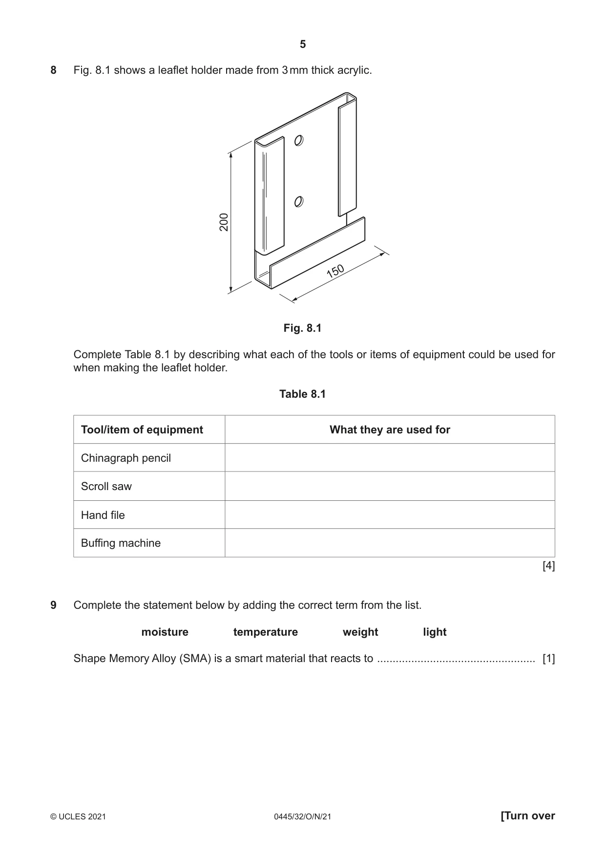
8 Fig. 8.1 shows a leaflet holder made from 3 mm thick acrylic. 200 150 Fig. 8.1 Complete Table 8.1 by describing what each of the tools or items of equipment could be used for when making the leaflet holder. Table 8.1 Tool/item of equipment What they are used for Chinagraph pencil Scroll saw Hand file Buffing machine [4]
Mark scheme: 8 Chinagraph pencil to mark out the shape of the holder 1 Scroll saw to cut out the shape 1 Hand file to work to the lines after sawing, smooth/flatten cut edges 1 Buffing machine to polish the acrylic, apply a finish, finishing, shine 1 Do not accept smooth the surfaces
Q9 · Complete the statement below by adding the correct term from the list
9 Complete the statement below by adding the correct term from the list. moisture temperature weight light Shape Memory Alloy (SMA) is a smart material that reacts to ................................................... [1]
Mark scheme: 9 Temperature 1
Q10 · The underside of a table top
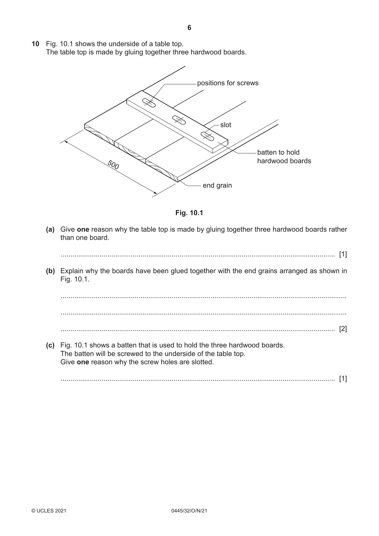
10 Fig. 10.1 shows the underside of a table top. The table top is made by gluing together three hardwood boards. positions for screws slot batten to hold 500 hardwood boards end grain Fig. 10.1 (a) Give one reason why the table top is made by gluing together three hardwood boards rather than one board. ............................................................................................................................................. [1] (b) Explain why the boards have been glued together with the end grains arranged as shown in Fig. 10.1. ................................................................................................................................................... ................................................................................................................................................... ............................................................................................................................................. [2] (c) Fig. 10.1 shows a batten that is used to hold the three hardwood boards. The batten will be screwed to the underside of the table top. Give one reason why the screw holes are slotted. ............................................................................................................................................. [1]
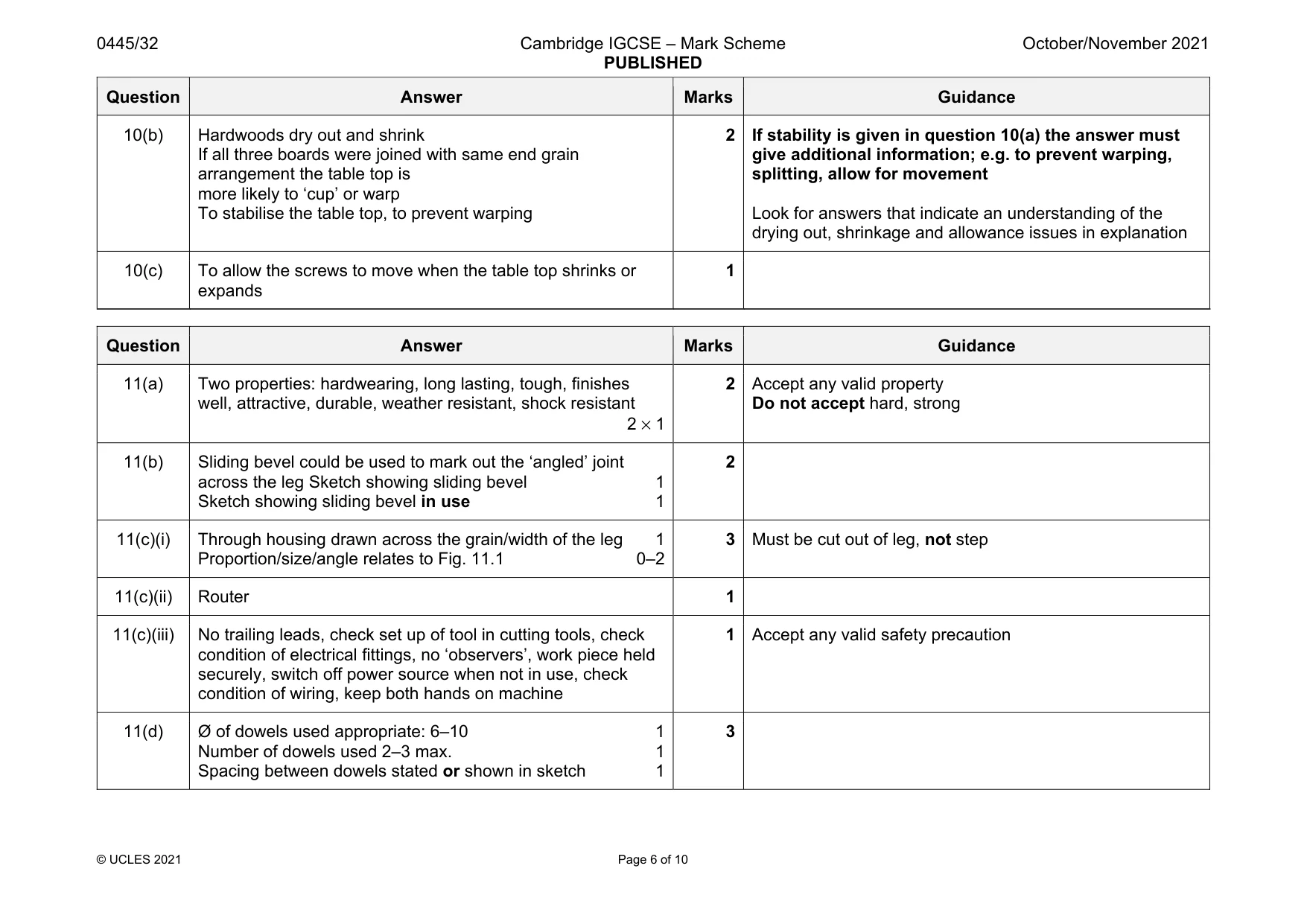
Mark scheme: 10(a) Hardwood boards of required width not available, to provide a stable table top 1 Do accept rigidity Question Answer Marks Guidance 10(b) Hardwoods dry out and shrink If all three boards were joined with same end grain arrangement the table top is more likely to ‘cup’ or warp To stabilise the table top, to prevent warping 2 If stability is given in question 10(a) the answer must give additional information; e.g. to prevent warping, splitting, allow for movement Look for answers that indicate an understanding of the drying out, shrinkage and allowance issues in explanation 10(c) To allow the screws to move when the table top shrinks or expands 1
Q11 · An incomplete design for a step stool made from oak
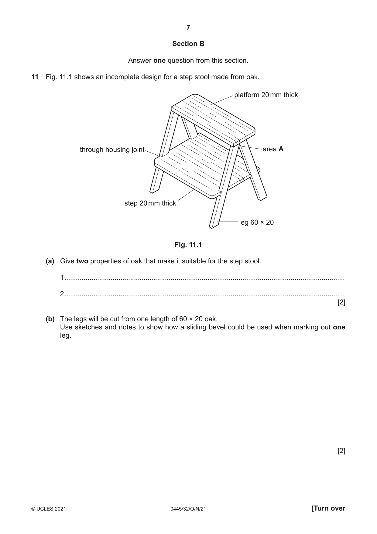
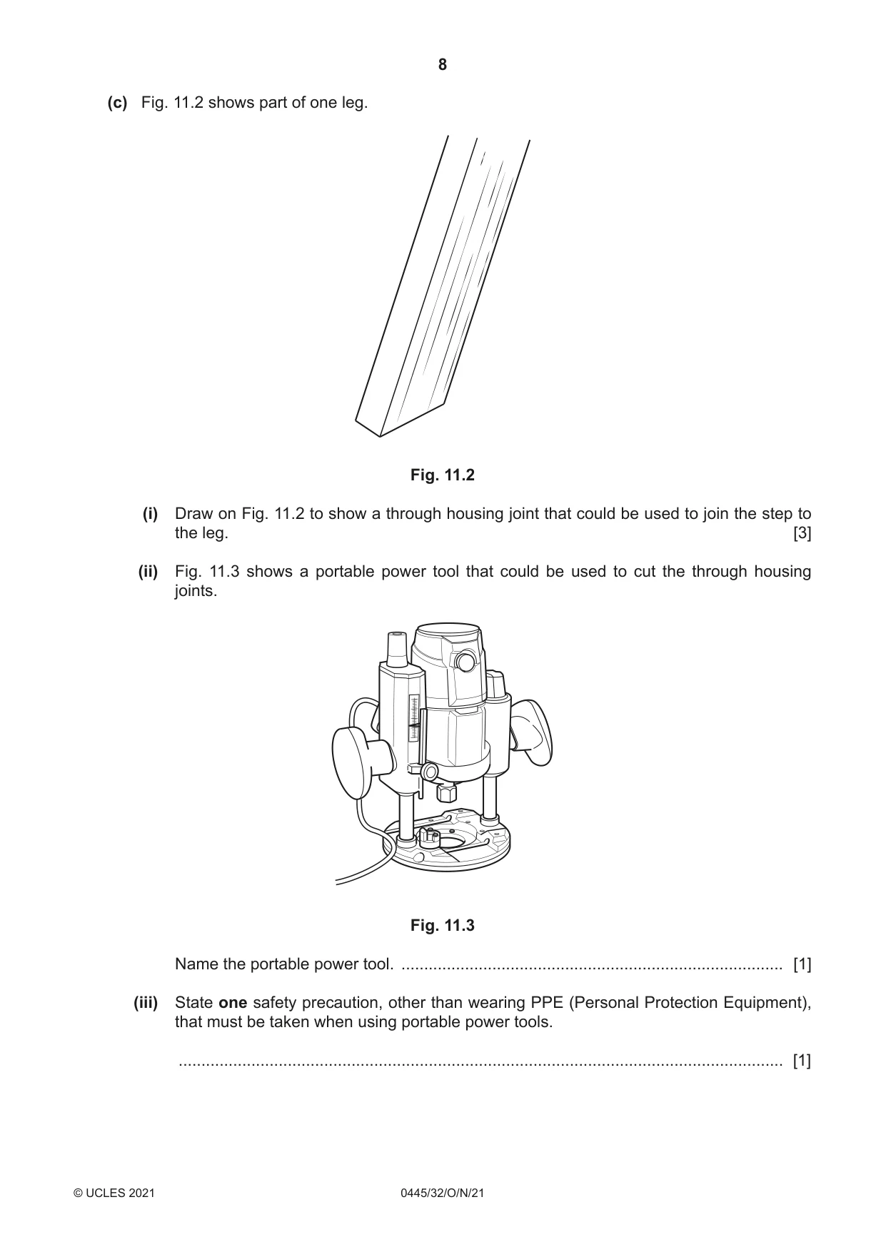
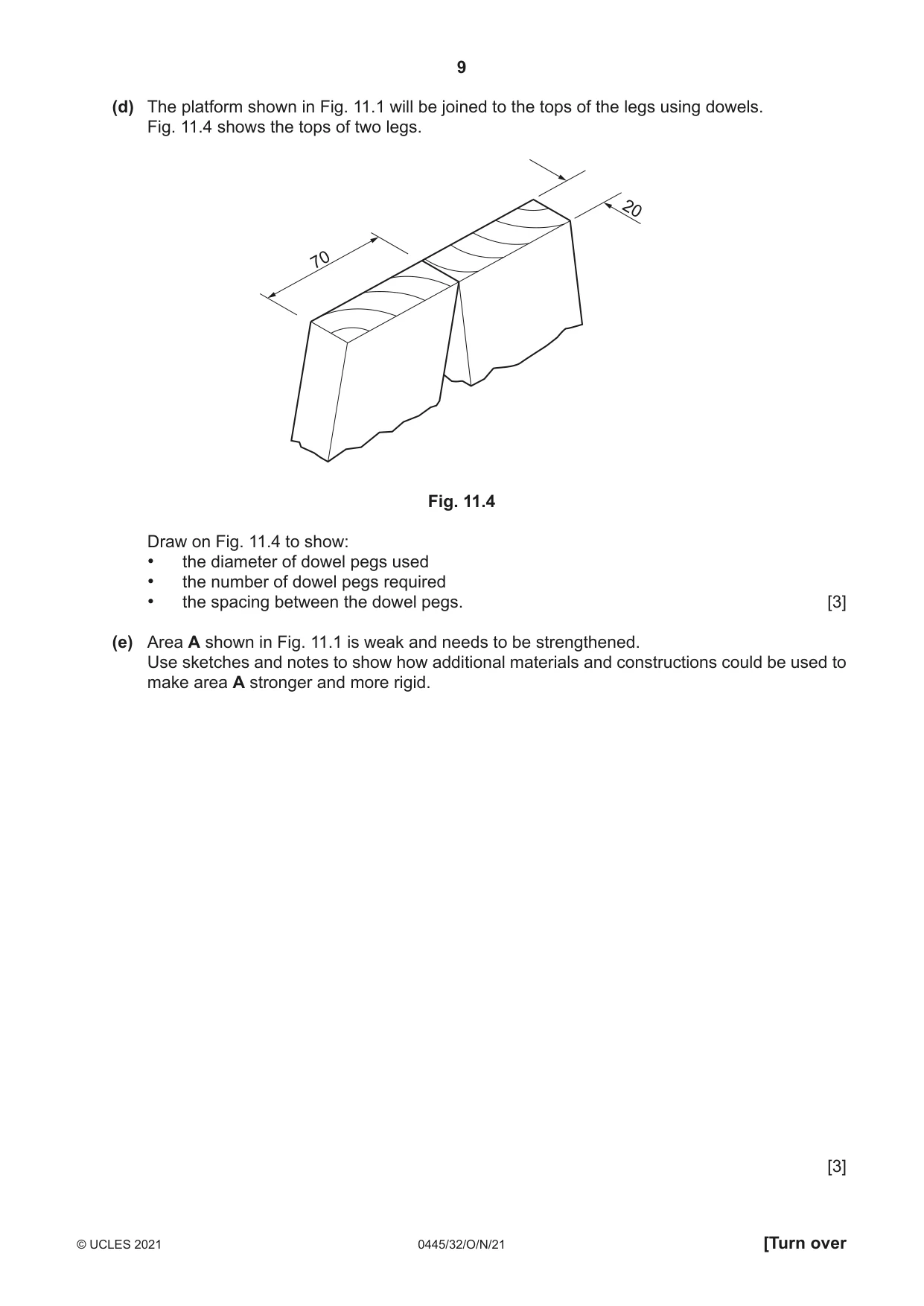
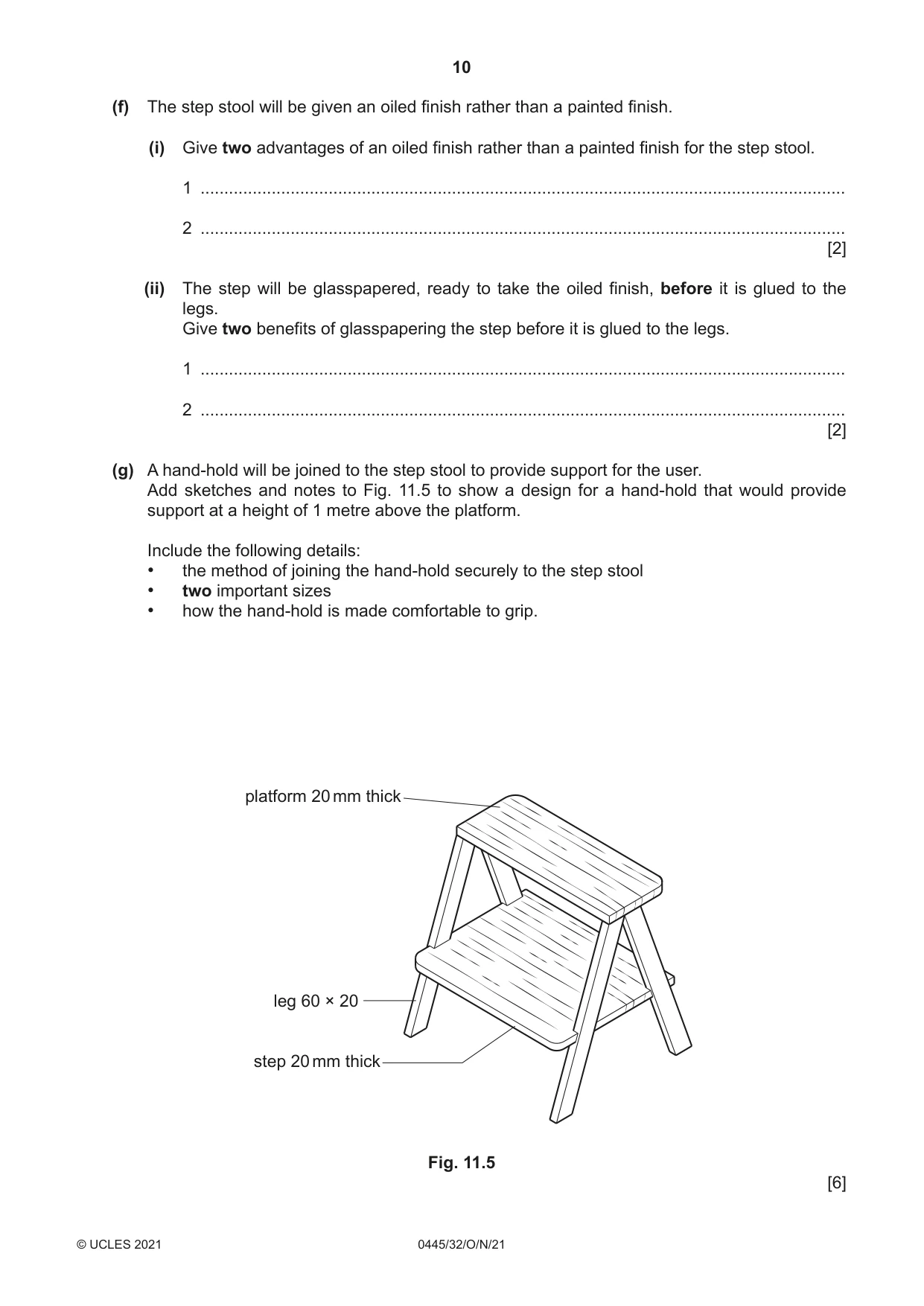
11 Fig. 11.1 shows an incomplete design for a step stool made from oak. platform 20 mm thick through housing joint area A step 20 mm thick leg 60 × 20 Fig. 11.1 (a) Give two properties of oak that make it suitable for the step stool. 1 ................................................................................................................................................. 2 ................................................................................................................................................. [2] (b) The legs will be cut from one length of 60 × 20 oak. Use sketches and notes to show how a sliding bevel could be used when marking out one leg. [2] (c) Fig. 11.2 shows part of one leg. Fig. 11.2 (i) Draw on Fig. 11.2 to show a through housing joint that could be used to join the step to the leg. [3] (ii) Fig. 11.3 shows a portable power tool that could be used to cut the through housing joints. Fig. 11.3 Name the portable power tool. .................................................................................... [1] (iii) State one safety precaution, other than wearing PPE (Personal Protection Equipment), that must be taken when using portable power tools. ..................................................................................................................................... [1] (d) The platform shown in Fig. 11.1 will be joined to the tops of the legs using dowels. Fig. 11.4 shows the tops of two legs. 20 70 Fig. 11.4 Draw on Fig. 11.4 to show: • the diameter of dowel pegs used • the number of dowel pegs required • the spacing between the dowel pegs. [3] (e) Area A shown in Fig. 11.1 is weak and needs to be strengthened. Use sketches and notes to show how additional materials and constructions could be used to make area A stronger and more rigid. [3] (f) The step stool will be given an oiled finish rather than a painted finish. (i) Give two advantages of an oiled finish rather than a painted finish for the step stool. 1 ........................................................................................................................................ 2 ........................................................................................................................................ [2] (ii) The step will be glasspapered, ready to take the oiled finish, before it is glued to the legs. Give two benefits of glasspapering the step before it is glued to the legs. 1 ........................................................................................................................................ 2 ........................................................................................................................................ [2] (g) A hand-hold will be joined to the step stool to provide support for the user. Add sketches and notes to Fig. 11.5 to show a design for a hand-hold that would provide support at a height of 1 metre above the platform. Include the following details: • the method of joining the hand-hold securely to the step stool • two important sizes • how the hand-hold is made comfortable to grip. platform 20 mm thick leg 60 × 20 step 20 mm thick Fig. 11.5 [6]
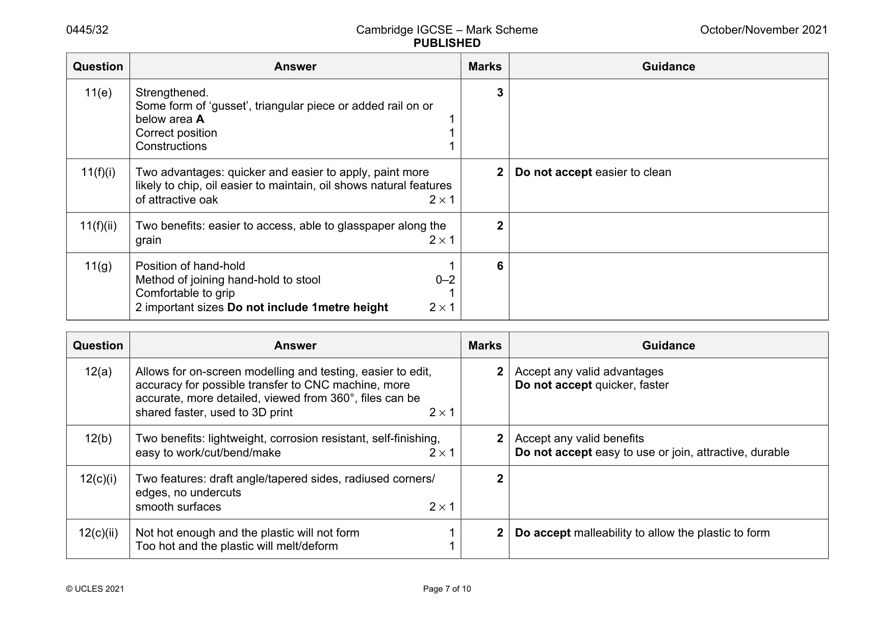
Mark scheme: 11(a) Two properties: hardwearing, long lasting, tough, finishes well, attractive, durable, weather resistant, shock resistant 2 × 1 2 Accept any valid property Do not accept hard, strong 11(b) Sliding bevel could be used to mark out the ‘angled’ joint across the leg Sketch showing sliding bevel 1 Sketch showing sliding bevel in use 1 2 11(c)(i) Through housing drawn across the grain/width of the leg 1 Proportion/size/angle relates to Fig. 11.1 0–2 3 Must be cut out of leg, not step 11(c)(ii) Router 1 11(c)(iii) No trailing leads, check set up of tool in cutting tools, check condition of electrical fittings, no ‘observers’, work piece held securely, switch off power source when not in use, check condition of wiring, keep both hands on machine 1 Accept any valid safety precaution 11(d) Ø of dowels used appropriate: 6–10 1 Number of dowels used 2–3 max. 1 Spacing between dowels stated or shown in sketch 1 3 Question Answer Marks Guidance 11(e) Strengthened. Some form of ‘gusset’, triangular piece or added rail on or below area A 1 Correct position 1 Constructions 1 3 11(f)(i) Two advantages: quicker and easier to apply, paint more likely to chip, oil easier to maintain, oil shows natural features of attractive oak 2 × 1 2 Do not accept easier to clean 11(f)(ii) Two benefits: easier to access, able to glasspaper along the grain 2 × 1 2 11(g) Position of hand-hold 1 Method of joining hand-hold to stool 0–2 Comfortable to grip 1 2 important sizes Do not include 1metre height 2 × 1 6
Q12 · Parts of an incomplete model car
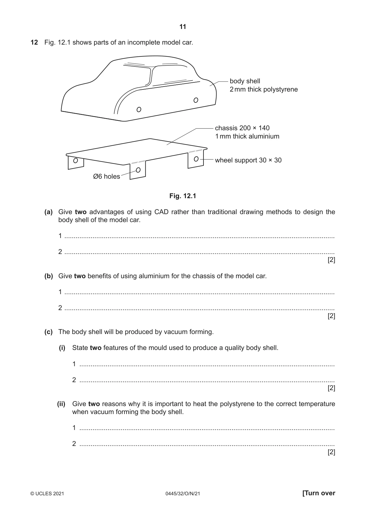
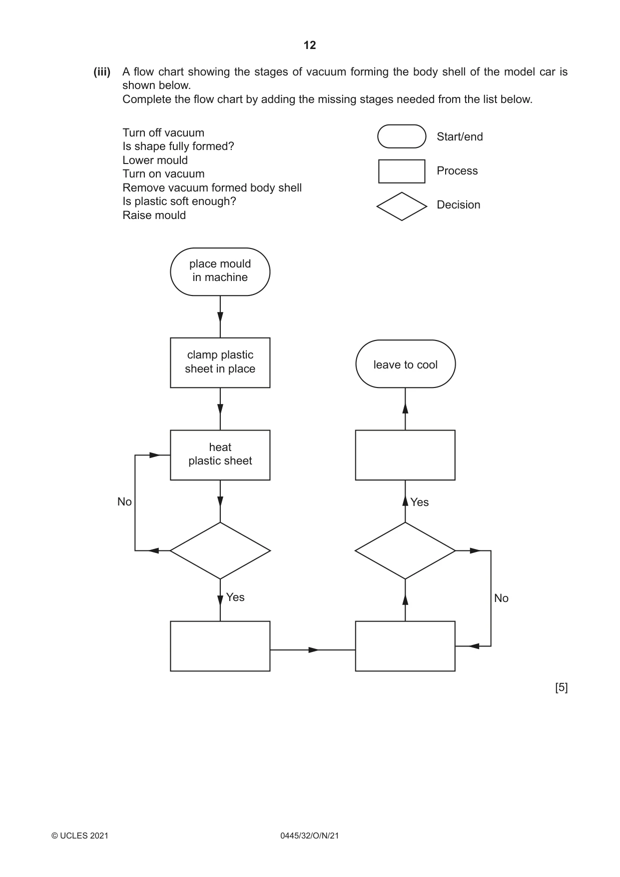
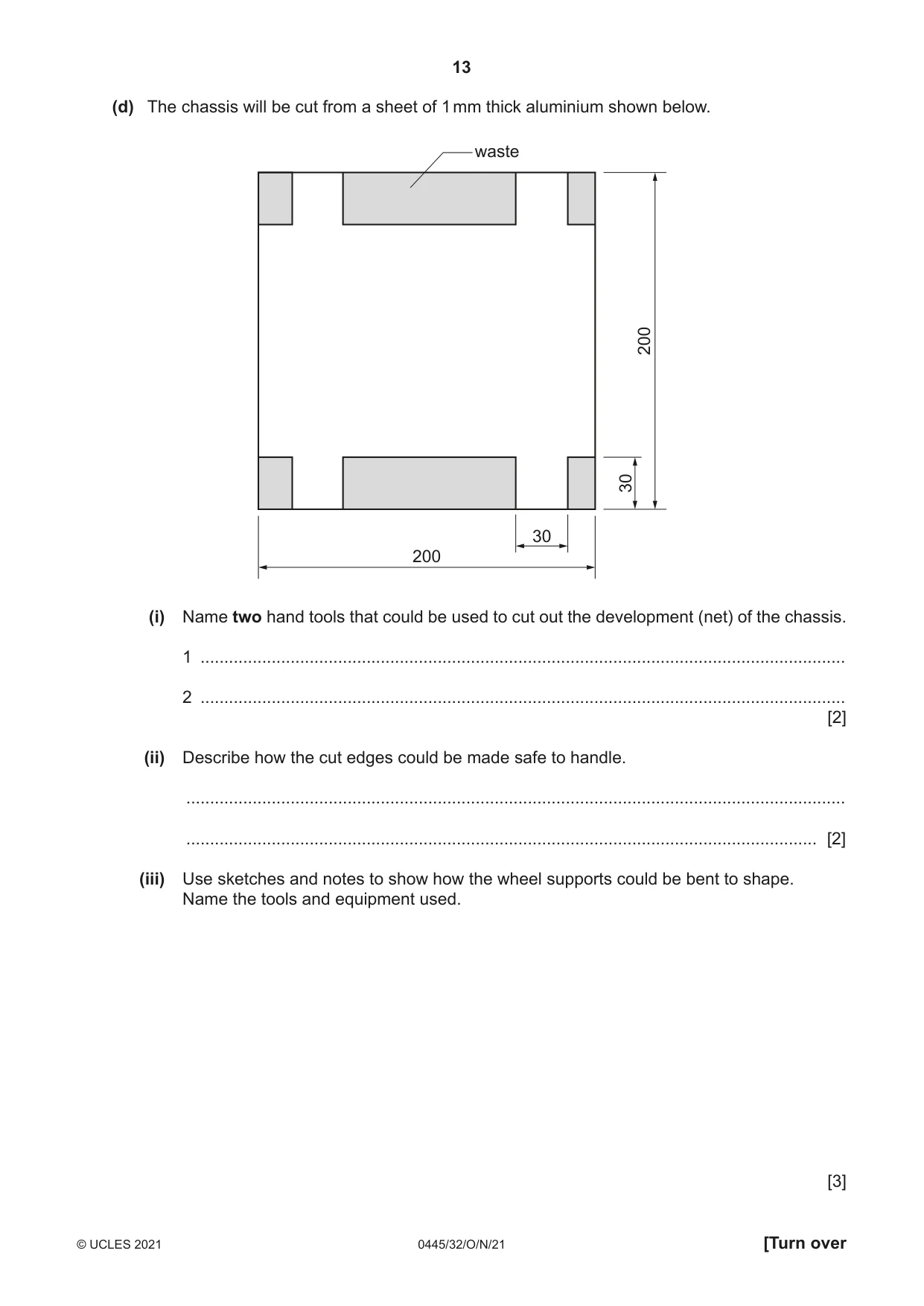
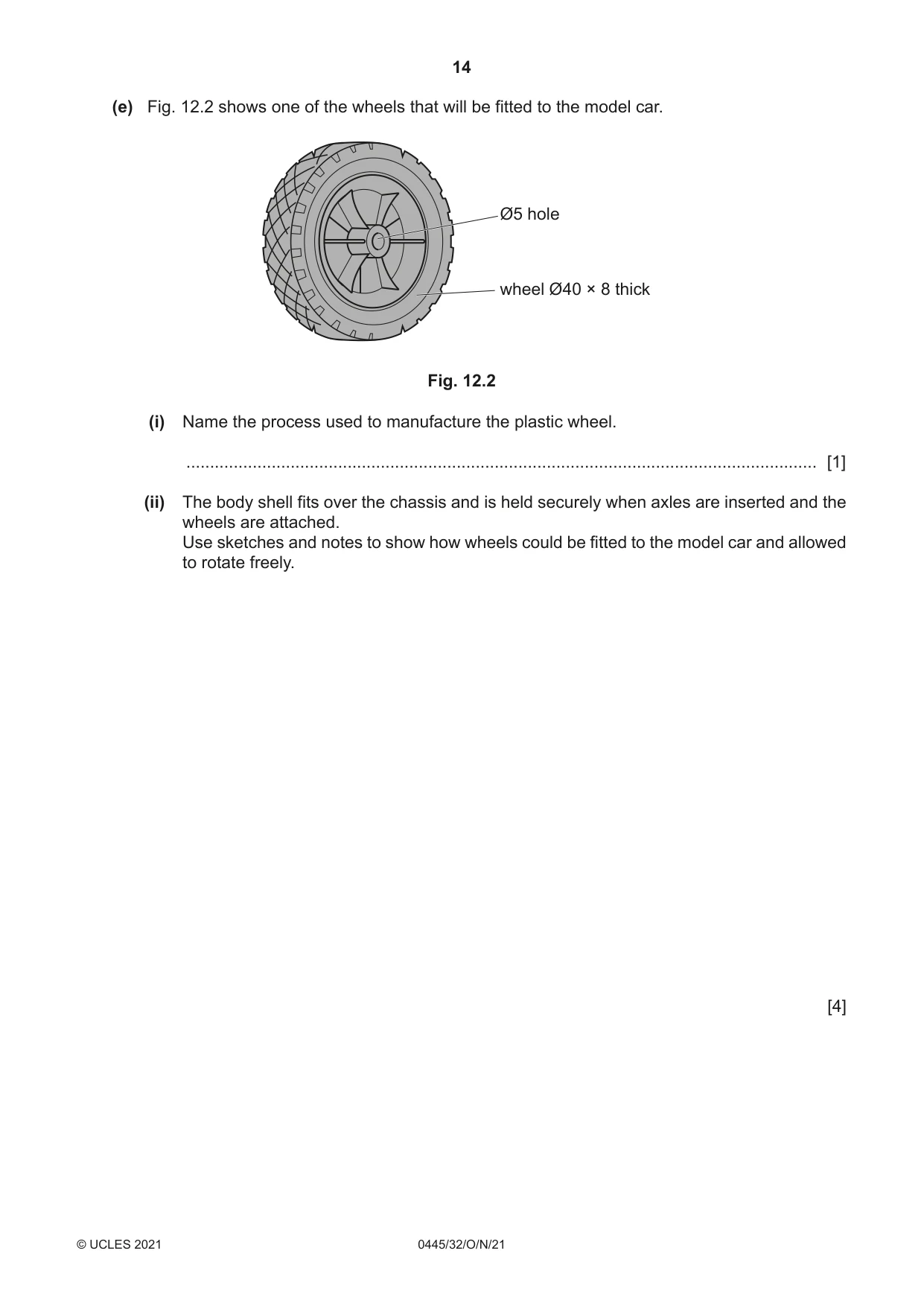
12 Fig. 12.1 shows parts of an incomplete model car. body shell 2 mm thick polystyrene chassis 200 × 140 1 mm thick aluminium wheel support 30 × 30 Ø6 holes Fig. 12.1 (a) Give two advantages of using CAD rather than traditional drawing methods to design the body shell of the model car. 1 ................................................................................................................................................ 2 ................................................................................................................................................ [2] (b) Give two benefits of using aluminium for the chassis of the model car. 1 ................................................................................................................................................ 2 ................................................................................................................................................ [2] (c) The body shell will be produced by vacuum forming. (i) State two features of the mould used to produce a quality body shell. 1 ........................................................................................................................................ 2 ........................................................................................................................................ [2] (ii) Give two reasons why it is important to heat the polystyrene to the correct temperature when vacuum forming the body shell. 1 ........................................................................................................................................ 2 ........................................................................................................................................ [2] (iii) A flow chart showing the stages of vacuum forming the body shell of the model car is shown below. Complete the flow chart by adding the missing stages needed from the list below. Turn off vacuum Start/end Is shape fully formed? Lower mould Turn on vacuum Process Remove vacuum formed body shell Is plastic soft enough? Decision Raise mould place mould in machine clamp plastic leave to cool sheet in place heat plastic sheet No Yes Yes No [5] (d) The chassis will be cut from a sheet of 1 mm thick aluminium shown below. waste 200 30 30 200 (i) Name two hand tools that could be used to cut out the development (net) of the chassis. 1 ........................................................................................................................................ 2 ........................................................................................................................................ [2] (ii) Describe how the cut edges could be made safe to handle. ........................................................................................................................................... ..................................................................................................................................... [2] (iii) Use sketches and notes to show how the wheel supports could be bent to shape. Name the tools and equipment used. [3] (e) Fig. 12.2 shows one of the wheels that will be fitted to the model car. Ø5 hole wheel Ø40 × 8 thick Fig. 12.2 (i) Name the process used to manufacture the plastic wheel. ..................................................................................................................................... [1] (ii) The body shell fits over the chassis and is held securely when axles are inserted and the wheels are attached. Use sketches and notes to show how wheels could be fitted to the model car and allowed to rotate freely. [4]
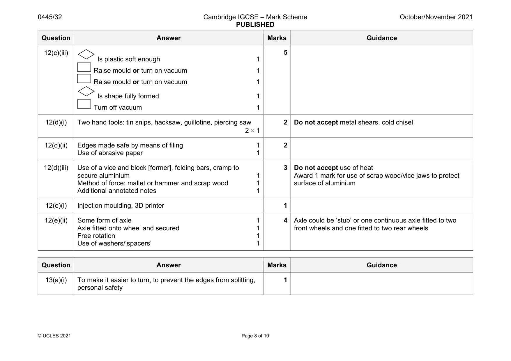
Mark scheme: 12(a) Allows for on-screen modelling and testing, easier to edit, accuracy for possible transfer to CNC machine, more accurate, more detailed, viewed from 360°, files can be shared faster, used to 3D print 2 × 1 Do not accept quicker, faster 12(b) Two benefits: lightweight, corrosion resistant, self-finishing, easy to work/cut/bend/make 2 × 1 2 Accept any valid benefits Do not accept easy to use or join, attractive, durable 12(c)(i) Two features: draft angle/tapered sides, radiused corners/ edges, no undercuts smooth surfaces 2 × 1 2 12(c)(ii) Not hot enough and the plastic will not form 1 Too hot and the plastic will melt/deform 1 2 Do accept malleability to allow the plastic to form Question Answer Marks Guidance 12(c)(iii) Is plastic soft enough 1 Raise mould or turn on vacuum 1 Raise mould or turn on vacuum 1 Is shape fully formed 1 Turn off vacuum 1 5 12(d)(i) Two hand tools: tin snips, hacksaw, guillotine, piercing saw 2 × 1 2 Do not accept metal shears, cold chisel 12(d)(ii) Edges made safe by means of filing 1 Use of abrasive paper 1 2 12(d)(iii) Use of a vice and block [former], folding bars, cramp to secure aluminium 1 Method of force: mallet or hammer and scrap wood 1 Additional annotated notes 1 3 Do not accept use of heat Award 1 mark for use of scrap wood/vice jaws to protect surface of aluminium 12(e)(i) Injection moulding, 3D printer 1 12(e)(ii) Some form of axle 1 Axle fitted onto wheel and secured 1 Free rotation 1 Use of washers/‘spacers’ 1 4 Axle could be ‘stub’ or one continuous axle fitted to two front wheels and one fitted to two rear wheels
Q13 · An incomplete design for a jewellery stand made from mahogany and brass
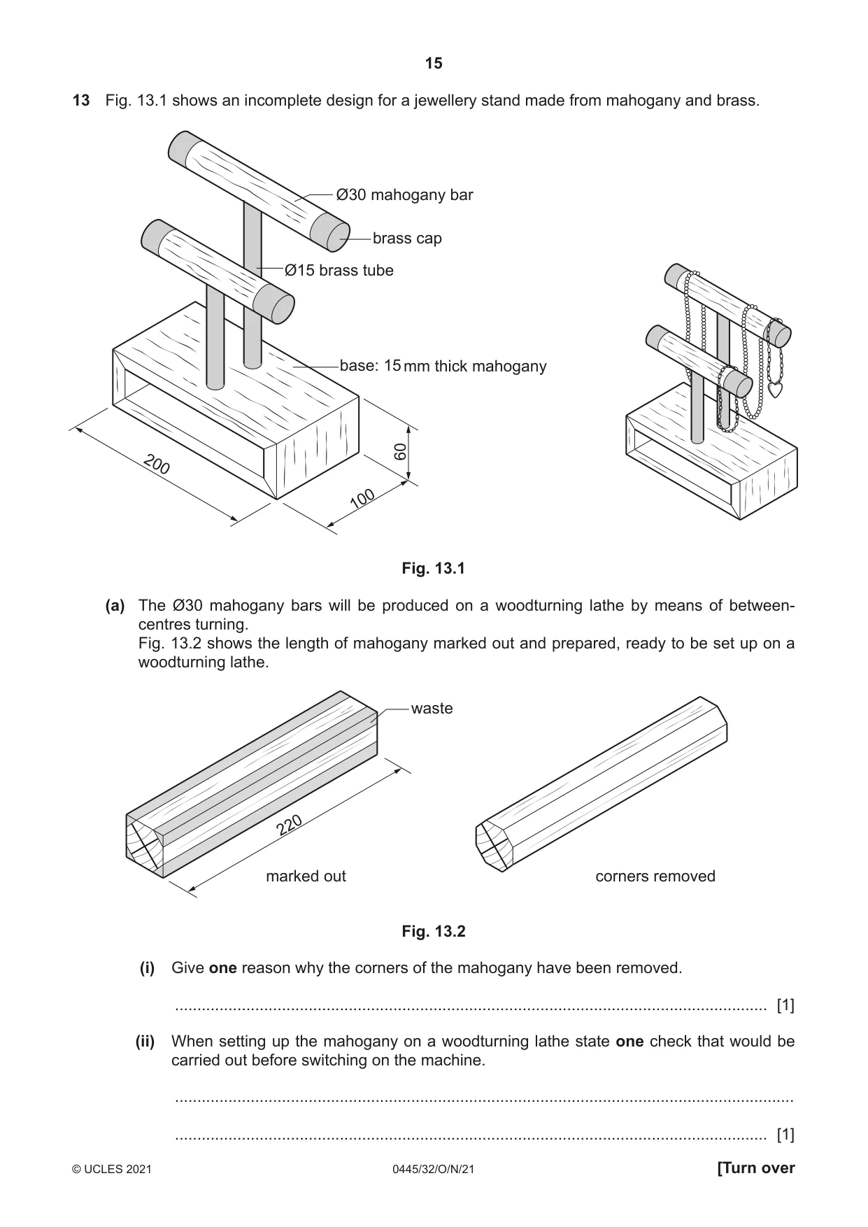
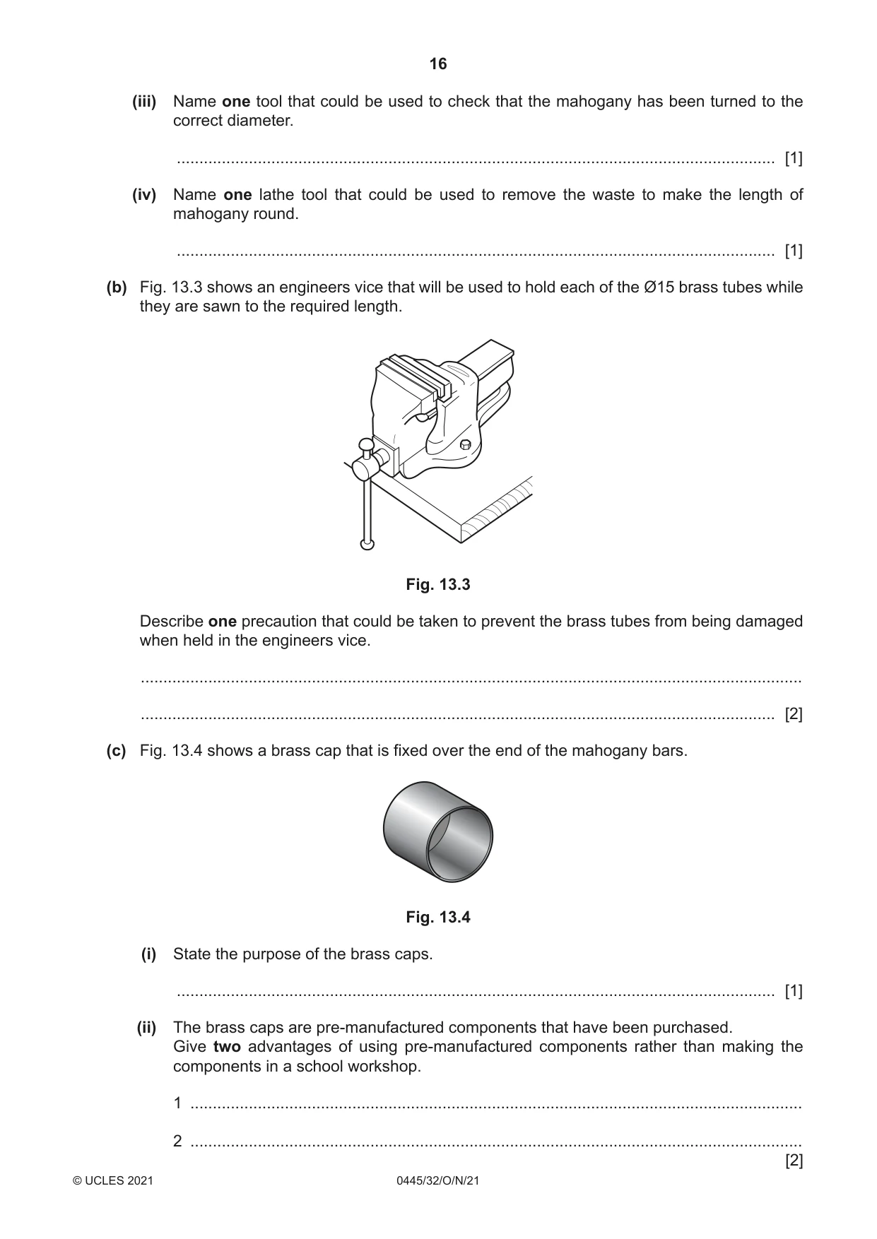
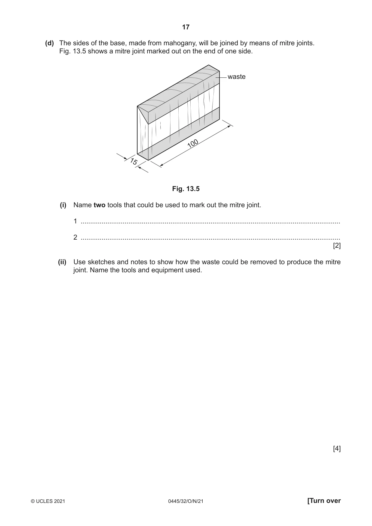
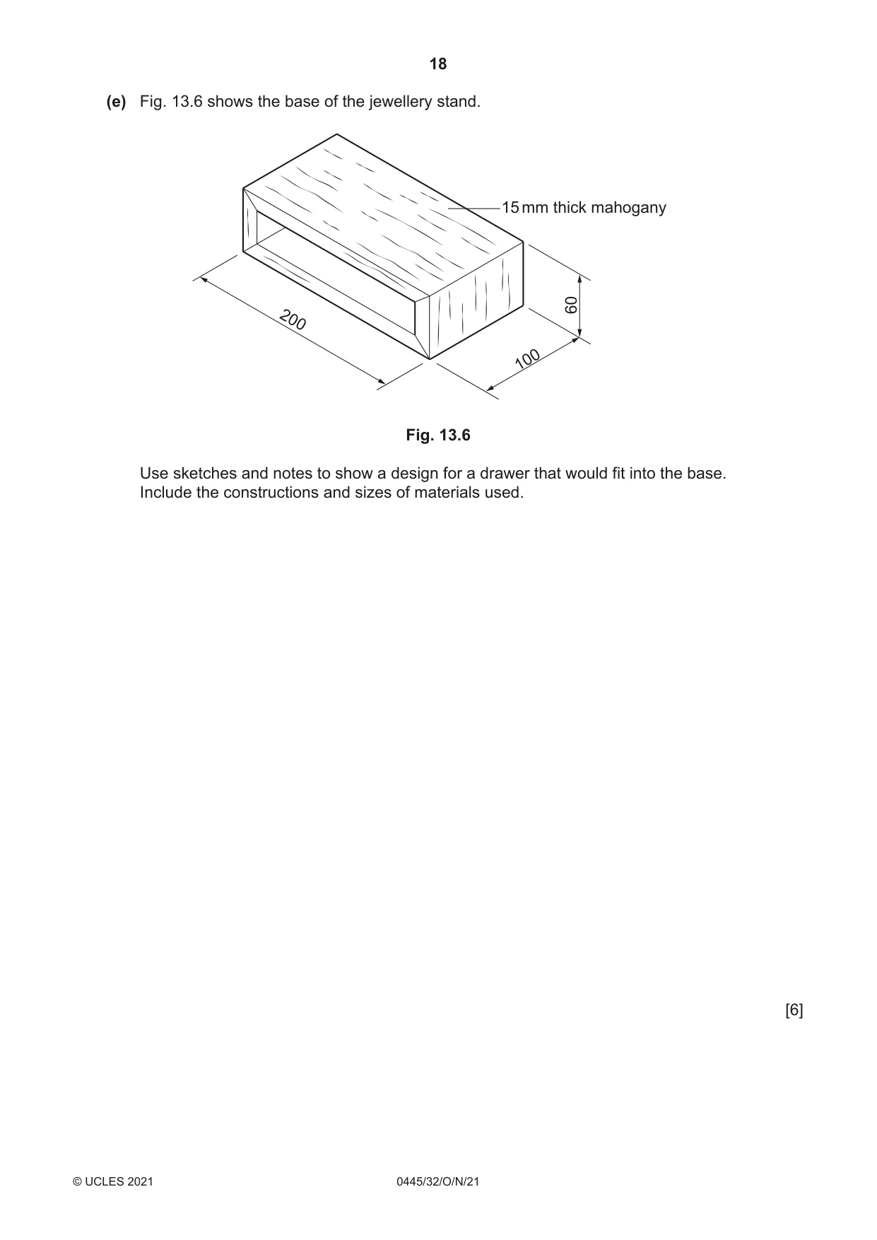
13 Fig. 13.1 shows an incomplete design for a jewellery stand made from mahogany and brass. Ø30 mahogany bar brass cap Ø15 brass tube base: 15 mm thick mahogany 60 200 100 Fig. 13.1 (a) The Ø30 mahogany bars will be produced on a woodturning lathe by means of between- centres turning. Fig. 13.2 shows the length of mahogany marked out and prepared, ready to be set up on a woodturning lathe. waste 220 marked out corners removed Fig. 13.2 (i) Give one reason why the corners of the mahogany have been removed. ..................................................................................................................................... [1] (ii) When setting up the mahogany on a woodturning lathe state one check that would be carried out before switching on the machine. ........................................................................................................................................... ..................................................................................................................................... [1] (iii) Name one tool that could be used to check that the mahogany has been turned to the correct diameter. ..................................................................................................................................... [1] (iv) Name one lathe tool that could be used to remove the waste to make the length of mahogany round. ..................................................................................................................................... [1] (b) Fig. 13.3 shows an engineers vice that will be used to hold each of the Ø15 brass tubes while they are sawn to the required length. Fig. 13.3 Describe one precaution that could be taken to prevent the brass tubes from being damaged when held in the engineers vice. ................................................................................................................................................... ............................................................................................................................................. [2] (c) Fig. 13.4 shows a brass cap that is fixed over the end of the mahogany bars. Fig. 13.4 (i) State the purpose of the brass caps. ..................................................................................................................................... [1] (ii) The brass caps are pre-manufactured components that have been purchased. Give two advantages of using pre-manufactured components rather than making the components in a school workshop. 1 ........................................................................................................................................ 2 ........................................................................................................................................ [2] (d) The sides of the base, made from mahogany, will be joined by means of mitre joints. Fig. 13.5 shows a mitre joint marked out on the end of one side. waste 100 15 Fig. 13.5 (i) Name two tools that could be used to mark out the mitre joint. 1 ........................................................................................................................................ 2 ........................................................................................................................................ [2] (ii) Use sketches and notes to show how the waste could be removed to produce the mitre joint. Name the tools and equipment used. [4]
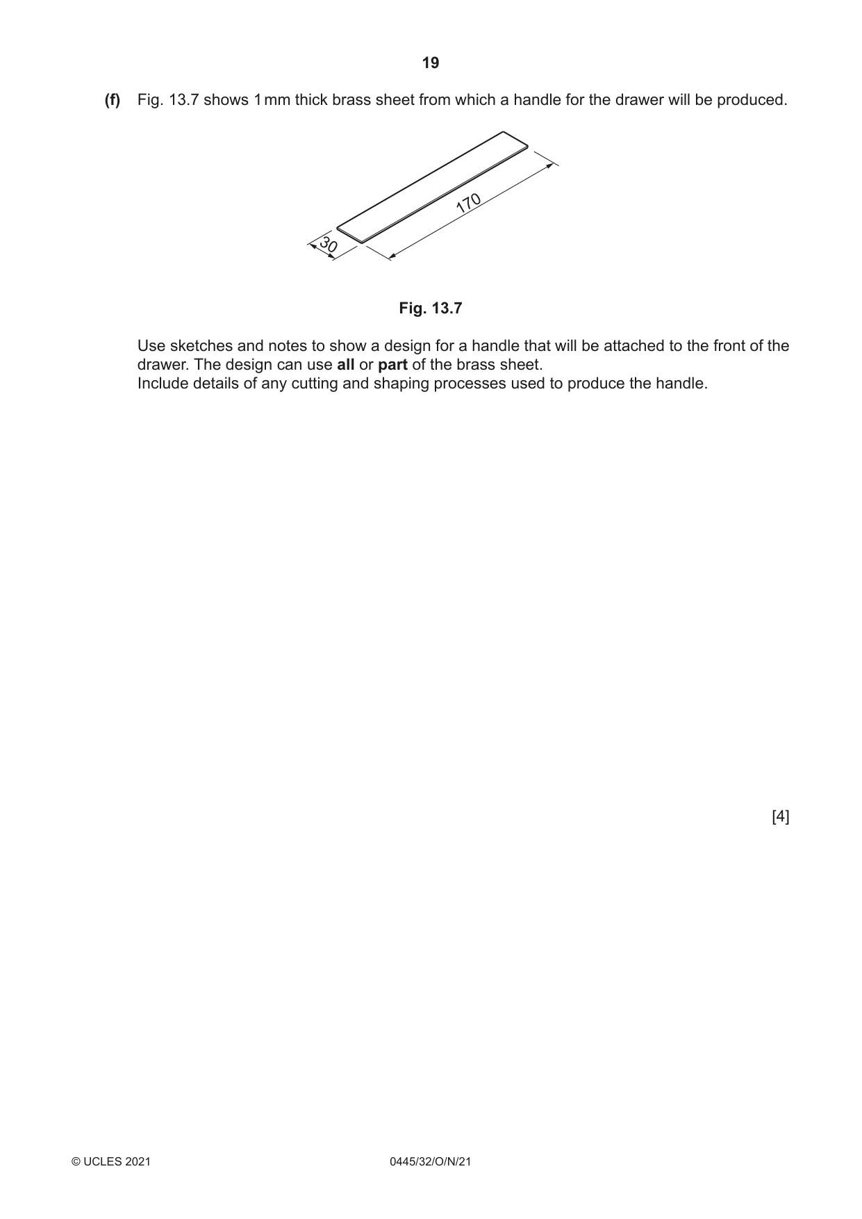
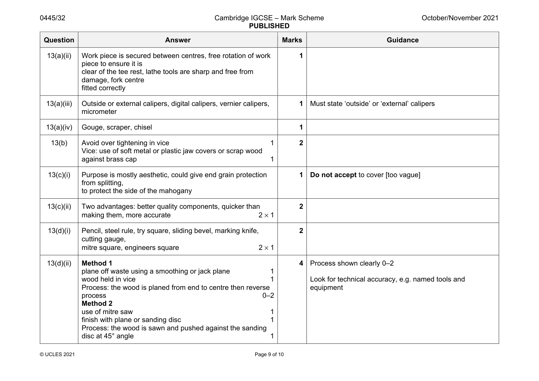
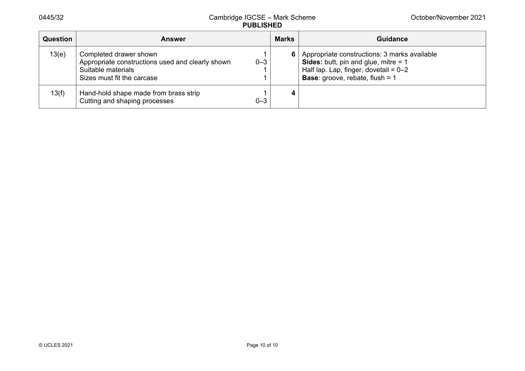
Mark scheme: 13(a)(i) To make it easier to turn, to prevent the edges from splitting, personal safety 1 Question Answer Marks Guidance 13(a)(ii) Work piece is secured between centres, free rotation of work piece to ensure it is clear of the tee rest, lathe tools are sharp and free from damage, fork centre fitted correctly 1 13(a)(iii) Outside or external calipers, digital calipers, vernier calipers, micrometer 1 Must state ‘outside’ or ‘external’ calipers 13(a)(iv) Gouge, scraper, chisel 1 13(b) Avoid over tightening in vice 1 Vice: use of soft metal or plastic jaw covers or scrap wood against brass cap 1 2 13(c)(i) Purpose is mostly aesthetic, could give end grain protection from splitting, to protect the side of the mahogany 1 Do not accept to cover [too vague] 13(c)(ii) Two advantages: better quality components, quicker than making them, more accurate 2 × 1 2 13(d)(i) Pencil, steel rule, try square, sliding bevel, marking knife, cutting gauge, mitre square, engineers square 2 × 1 2 13(d)(ii) Method 1 plane off waste using a smoothing or jack plane 1 wood held in vice 1 Process: the wood is planed from end to centre then reverse process 0–2 Method 2 use of mitre saw 1 finish with plane or sanding disc 1 Process: the wood is sawn and pushed against the sanding disc at 45° angle 1 4 Process shown clearly 0–2 Look for technical accuracy, e.g. named tools and equipment Question Answer Marks Guidance 13(e) Completed drawer shown 1 Appropriate constructions used and clearly shown 0–3 Suitable materials 1 Sizes must fit the carcase 1 6 Appropriate constructions: 3 marks available Sides: butt, pin and glue, mitre = 1 Half lap. Lap, finger, dovetail = 0–2 Base: groove, rebate, flush = 1 13(f) Hand-hold shape made from brass strip 1 Cutting and shaping processes 0–3 4
What was in this paper
The subtopics covered by these 13 questions, and how many questions each got. Open one in a new tab to see every Cambridge question on it.
What you needed in this session
Cambridge’s own grade thresholds for 2021 Oct/Nov, Paper 3 · Variant 2. A higher threshold means an easier paper — the bar moves with how the cohort did.