Cambridge IGCSE Design and Technology 0445 — 2021 May/June Paper 3 · Variant 2
0445/32/M/J/21 · 13 questions · 50 marks · ≈56 min
The question paper and its mark scheme, free to read here and free to download. This is Cambridge’s own paper, exactly as it was sat.
Question paper24 pages


Mark scheme10 pages
Answers below. Sit the paper first if you are practising.
Questions as text
Q1 · A workshop operation where there is a danger of damaging the material
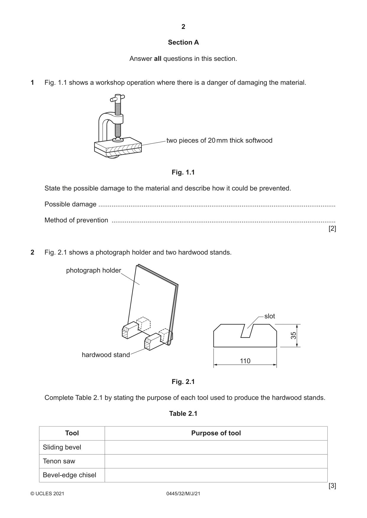
1 Fig. 1.1 shows a workshop operation where there is a danger of damaging the material. two pieces of 20 mm thick softwood Fig. 1.1 State the possible damage to the material and describe how it could be prevented. Possible damage .............................................................................................................................. Method of prevention ....................................................................................................................... [2]
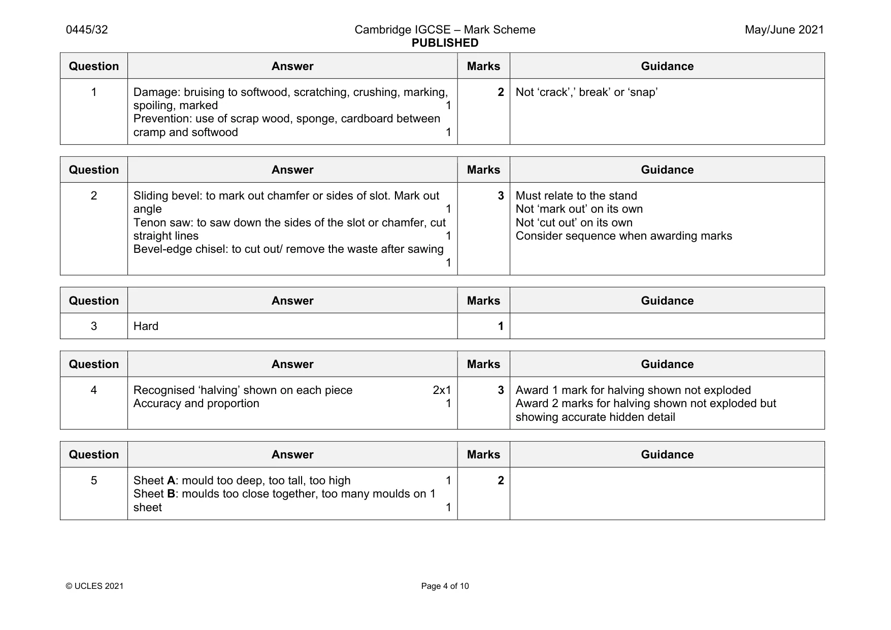
Mark scheme: 1 Damage: bruising to softwood, scratching, crushing, marking, spoiling, marked 1 Prevention: use of scrap wood, sponge, cardboard between cramp and softwood 1 2 Not ‘crack’,’ break’ or ‘snap’
Q2 · A photograph holder and two hardwood stands
2 Fig. 2.1 shows a photograph holder and two hardwood stands. photograph holder slot 35 hardwood stand 110 Fig. 2.1 Complete Table 2.1 by stating the purpose of each tool used to produce the hardwood stands. Table 2.1 Tool Purpose of tool Sliding bevel Tenon saw Bevel-edge chisel [3]
Mark scheme: 2 Sliding bevel: to mark out chamfer or sides of slot. Mark out angle 1 Tenon saw: to saw down the sides of the slot or chamfer, cut straight lines 1 Bevel-edge chisel: to cut out/ remove the waste after sawing 1 Not ‘mark out’ on its own Not ‘cut out’ on its own Consider sequence when awarding marks
Q3 · Complete the statement below by adding the correct term from the list
3 Complete the statement below by adding the correct term from the list. soft flexible hard corrosion resistant Steel that contains a high amount of carbon is very .................................................................. [1]
Mark scheme: 3 Hard 1
Question 4
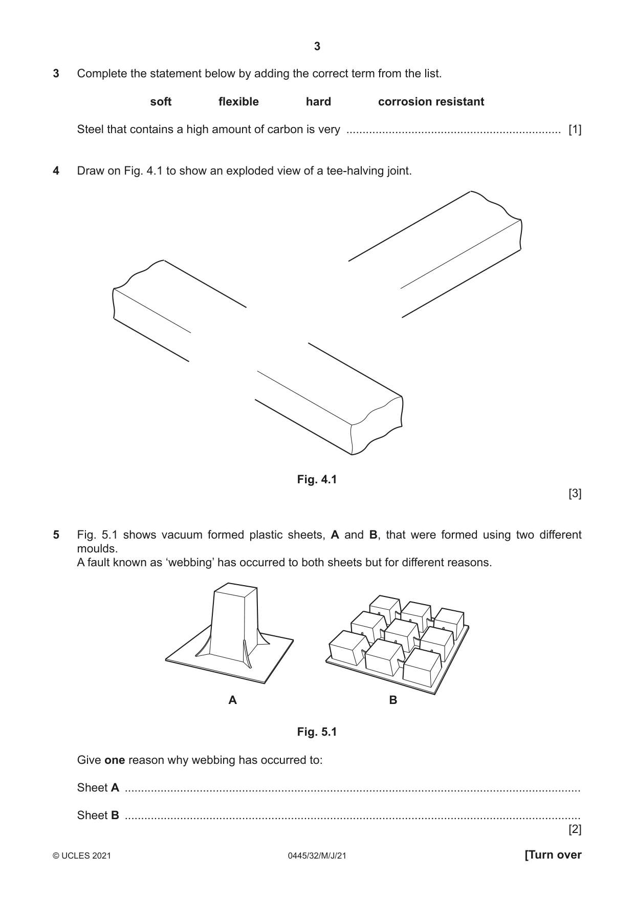
4 Draw on Fig. 4.1 to show an exploded view of a tee-halving joint. Fig. 4.1 [3]
Mark scheme: 4 Recognised ‘halving’ shown on each piece 2x1 Accuracy and proportion 1 3 Award 1 mark for halving shown not exploded Award 2 marks for halving shown not exploded but showing accurate hidden detail
Q5 · Vacuum formed plastic sheets, A and B, that were formed using two different moulds
5 Fig. 5.1 shows vacuum formed plastic sheets, A and B, that were formed using two different moulds. A fault known as ‘webbing’ has occurred to both sheets but for different reasons. A B Fig. 5.1 Give one reason why webbing has occurred to: Sheet A ............................................................................................................................................ Sheet B ............................................................................................................................................ [2]
Mark scheme: 5 Sheet A: mould too deep, too tall, too high 1 Sheet B: moulds too close together, too many moulds on 1 sheet 1 2
Q6 · Two lengths of 5 mm thick mild steel strip with pre-drilled holes
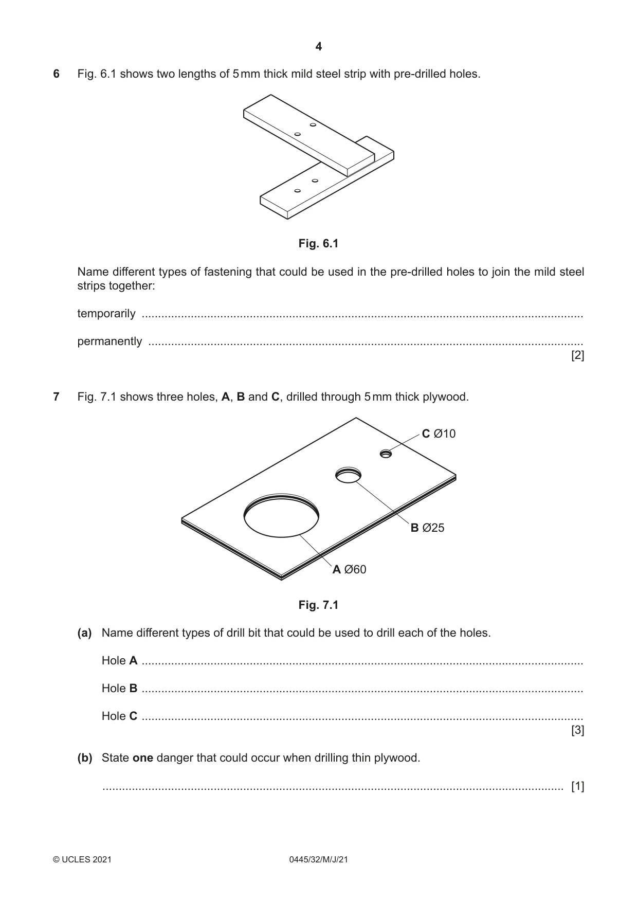
6 Fig. 6.1 shows two lengths of 5 mm thick mild steel strip with pre-drilled holes. Fig. 6.1 Name different types of fastening that could be used in the pre-drilled holes to join the mild steel strips together: temporarily ....................................................................................................................................... permanently ..................................................................................................................................... [2]
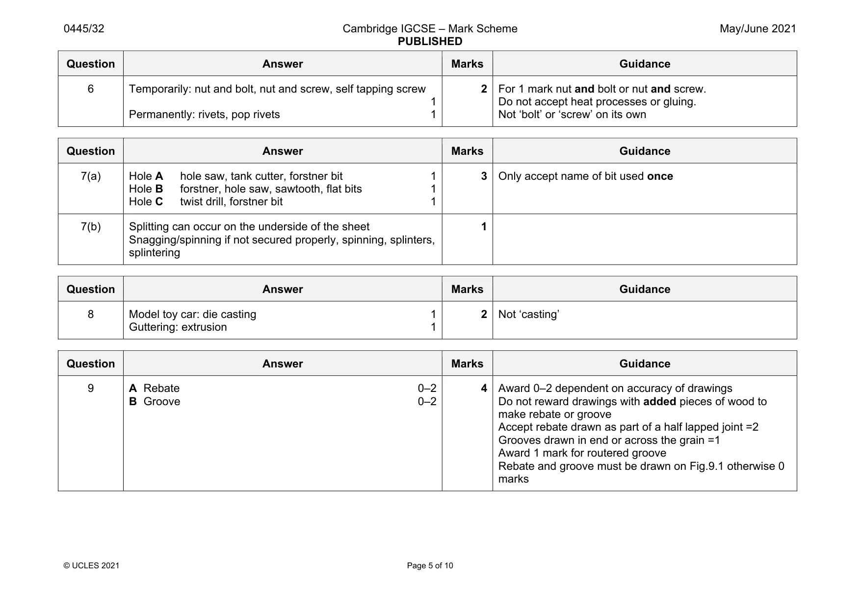
Mark scheme: 6 Temporarily: nut and bolt, nut and screw, self tapping screw 1 Permanently: rivets, pop rivets 1 2 For 1 mark nut and bolt or nut and screw. Do not accept heat processes or gluing. Not ‘bolt’ or ‘screw’ on its own
Q7 · Three holes, A, B and C, drilled through 5 mm thick plywood
7 Fig. 7.1 shows three holes, A, B and C, drilled through 5 mm thick plywood. C Ø10 B Ø25 A Ø60 Fig. 7.1 (a) Name different types of drill bit that could be used to drill each of the holes. Hole A ....................................................................................................................................... Hole B ....................................................................................................................................... Hole C ....................................................................................................................................... [3] (b) State one danger that could occur when drilling thin plywood. ............................................................................................................................................. [1]
Mark scheme: 7(a) Hole A hole saw, tank cutter, forstner bit 1 Hole B forstner, hole saw, sawtooth, flat bits 1 Hole C twist drill, forstner bit 1 3 Only accept name of bit used once 7(b) Splitting can occur on the underside of the sheet Snagging/spinning if not secured properly, spinning, splinters, splintering 1
Q8 · Complete Table 8.1 by stating the manufacturing process used to make each product
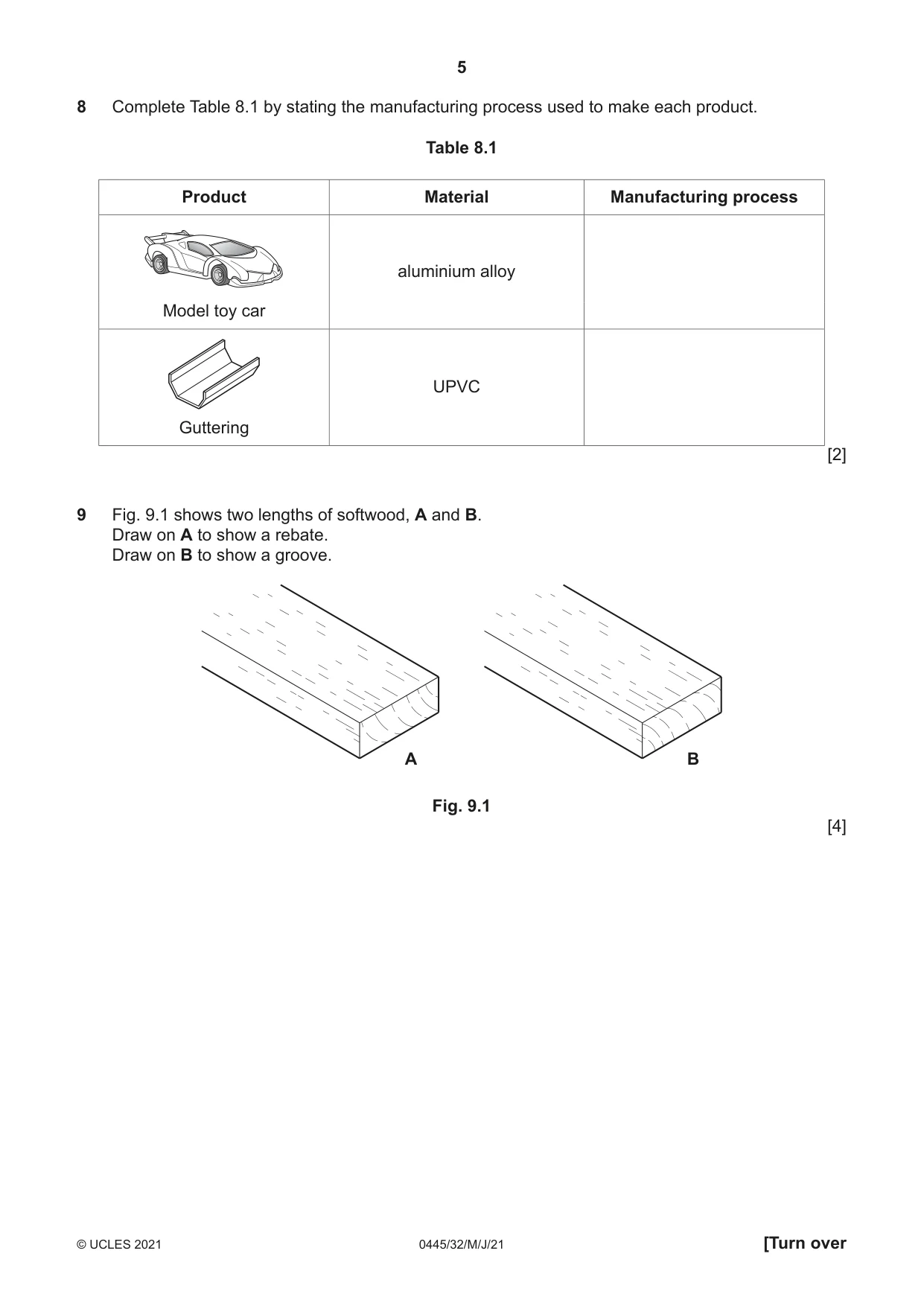
8 Complete Table 8.1 by stating the manufacturing process used to make each product. Table 8.1 Product Material Manufacturing process aluminium alloy Model toy car UPVC Guttering [2]
Mark scheme: 8 Model toy car: die casting 1 Guttering: extrusion 1 2 Not ‘casting’
Q9 · Two lengths of softwood, A and B
9 Fig. 9.1 shows two lengths of softwood, A and B. Draw on A to show a rebate. Draw on B to show a groove. A B Fig. 9.1 [4]
Mark scheme: 9 A Rebate 0–2 B Groove 0–2 4 Award 0–2 dependent on accuracy of drawings Do not reward drawings with added pieces of wood to make rebate or groove Accept rebate drawn as part of a half lapped joint =2 Grooves drawn in end or across the grain =1 Award 1 mark for routered groove Rebate and groove must be drawn on Fig.9.1 otherwise 0 marks
Q10 · Equipment used to apply an attractive finish on an aluminium product
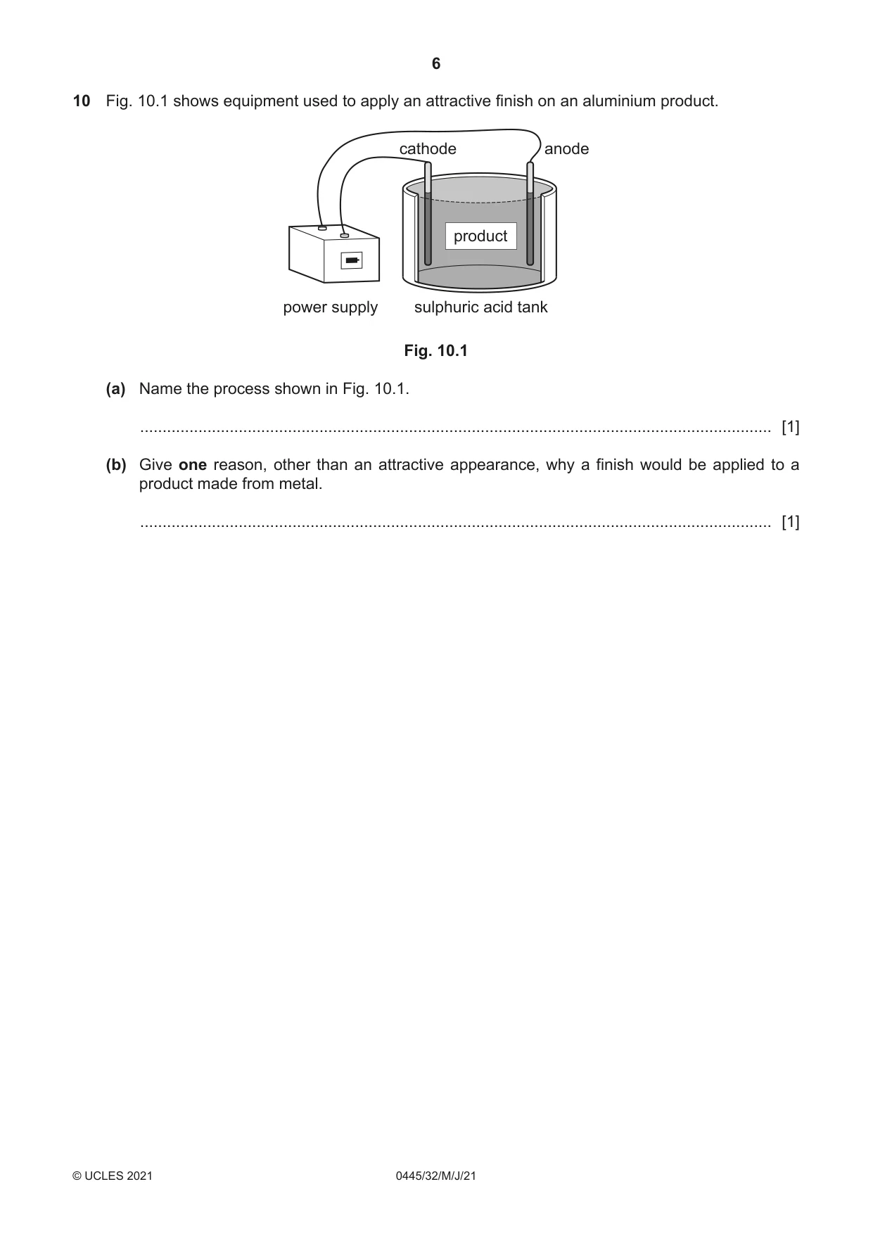
10 Fig. 10.1 shows equipment used to apply an attractive finish on an aluminium product. cathode anode product power supply sulphuric acid tank Fig. 10.1 (a) Name the process shown in Fig. 10.1. ............................................................................................................................................. [1] (b) Give one reason, other than an attractive appearance, why a finish would be applied to a product made from metal. ............................................................................................................................................. [1]
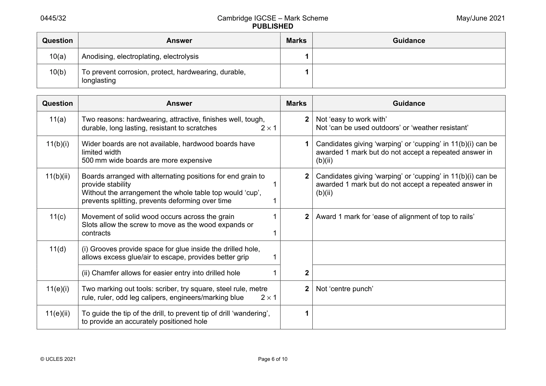
Mark scheme: 10(a) Anodising, electroplating, electrolysis 1 10(b) To prevent corrosion, protect, hardwearing, durable, longlasting 1
Q11 · A table made from oak with a detachable magazine rack made from acrylic
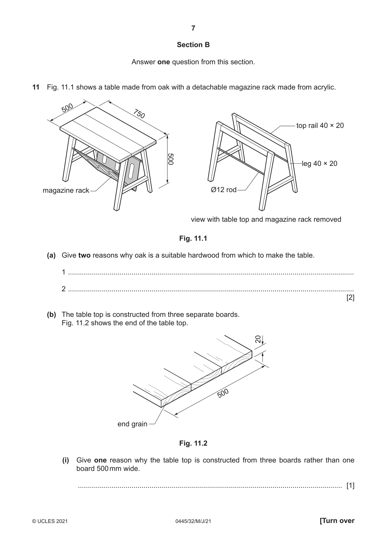
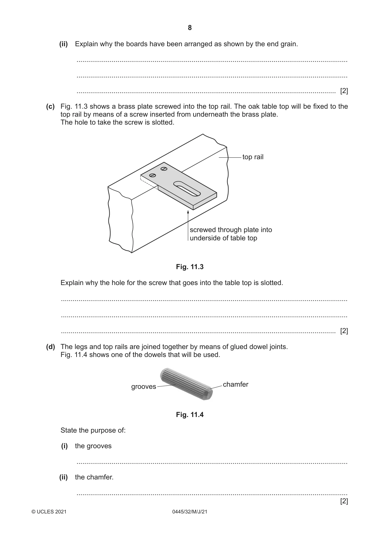
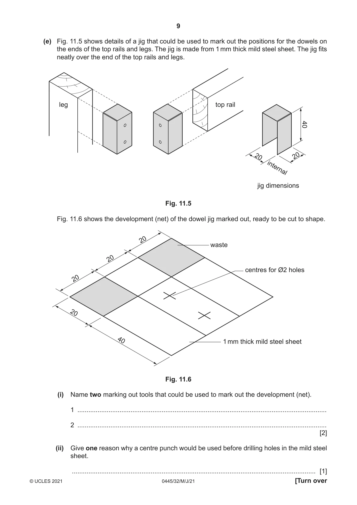
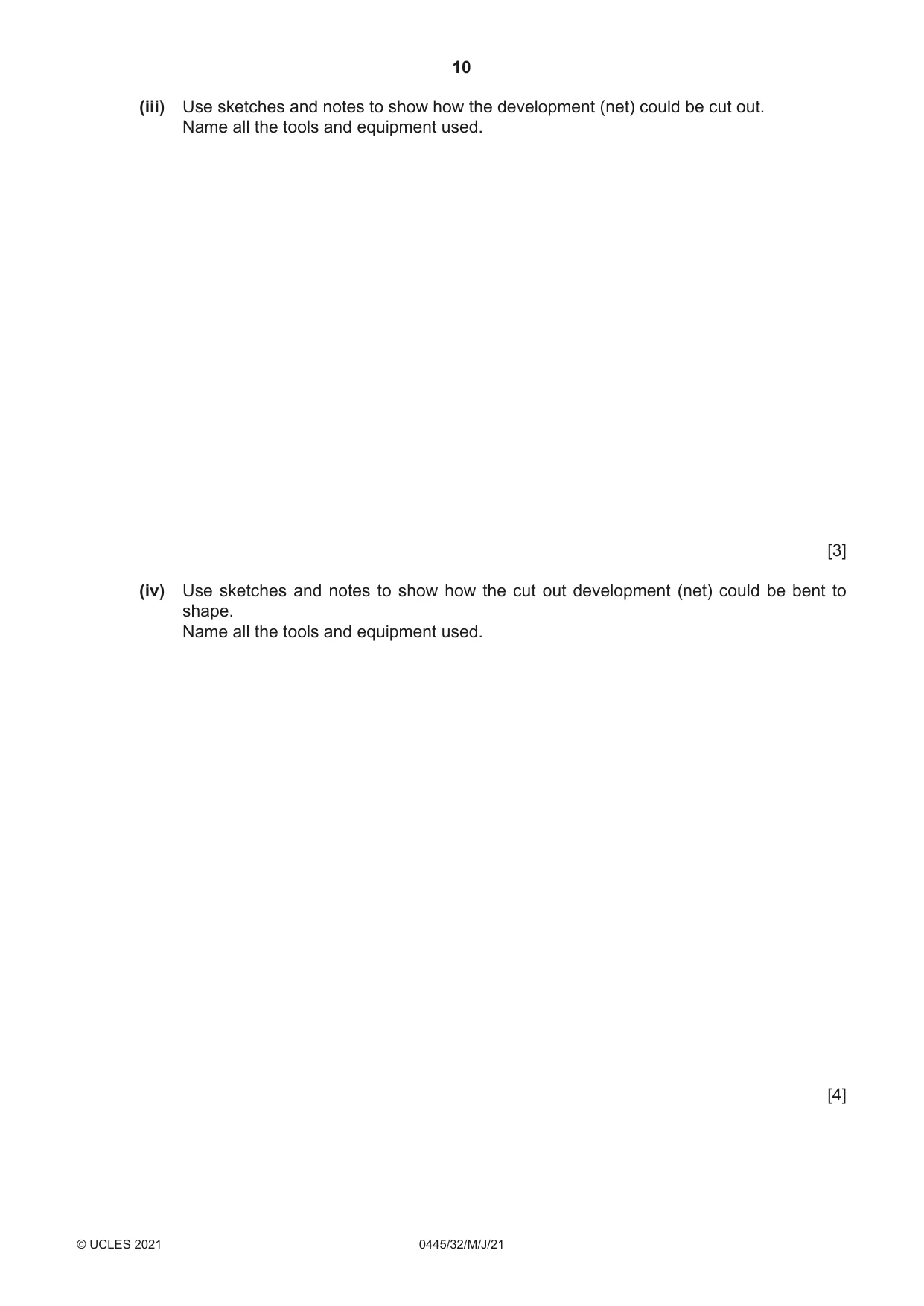
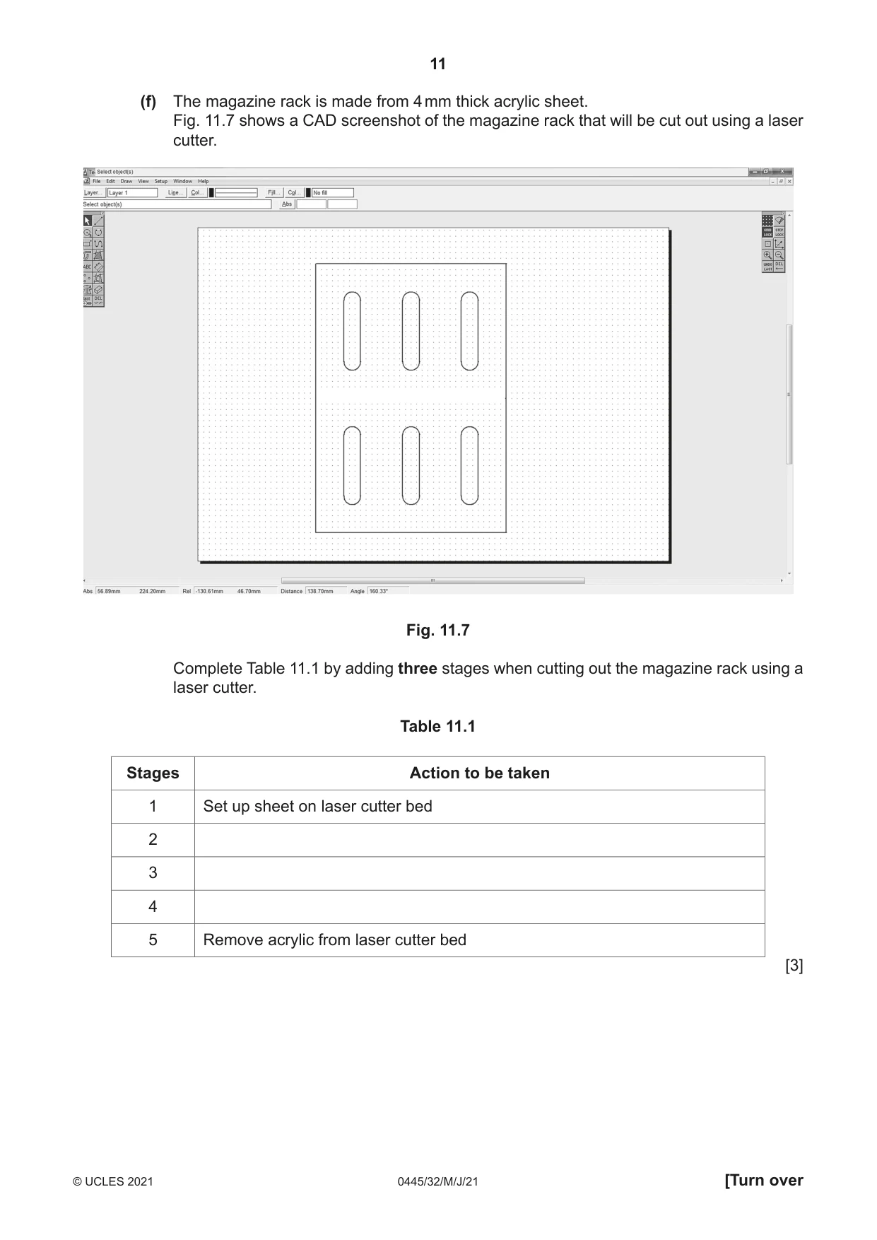
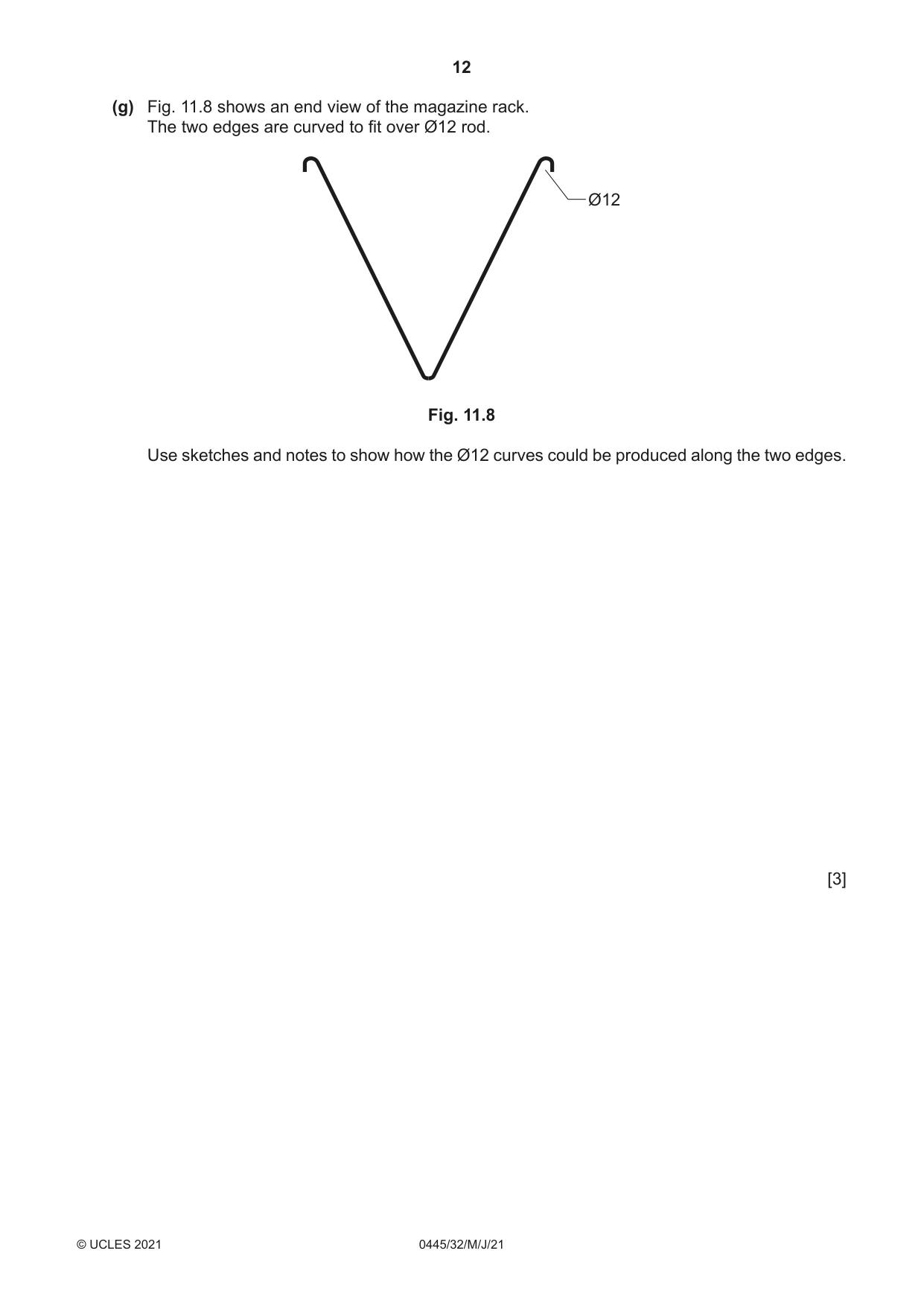
11 Fig. 11.1 shows a table made from oak with a detachable magazine rack made from acrylic. 500 750 top rail 40 × 20 500 leg 40 × 20 magazine rack Ø12 rod view with table top and magazine rack removed Fig. 11.1 (a) Give two reasons why oak is a suitable hardwood from which to make the table. 1 ................................................................................................................................................ 2 ................................................................................................................................................ [2] (b) The table top is constructed from three separate boards. Fig. 11.2 shows the end of the table top. 20 500 end grain Fig. 11.2 (i) Give one reason why the table top is constructed from three boards rather than one board 500 mm wide. ..................................................................................................................................... [1] (ii) Explain why the boards have been arranged as shown by the end grain. ........................................................................................................................................... ........................................................................................................................................... ..................................................................................................................................... [2] (c) Fig. 11.3 shows a brass plate screwed into the top rail. The oak table top will be fixed to the top rail by means of a screw inserted from underneath the brass plate. The hole to take the screw is slotted. top rail screwed through plate into underside of table top Fig. 11.3 Explain why the hole for the screw that goes into the table top is slotted. ................................................................................................................................................... ................................................................................................................................................... ............................................................................................................................................. [2] (d) The legs and top rails are joined together by means of glued dowel joints. Fig. 11.4 shows one of the dowels that will be used. chamfer grooves Fig. 11.4 State the purpose of: (i) the grooves ........................................................................................................................................... (ii) the chamfer. ........................................................................................................................................... [2] (e) Fig. 11.5 shows details of a jig that could be used to mark out the positions for the dowels on the ends of the top rails and legs. The jig is made from 1 mm thick mild steel sheet. The jig fits neatly over the end of the top rails and legs. leg top rail 40 20 20 internal jig dimensions Fig. 11.5 Fig. 11.6 shows the development (net) of the dowel jig marked out, ready to be cut to shape. 20 waste 20 centres for Ø2 holes 20 20 40 1 mm thick mild steel sheet Fig. 11.6 (i) Name two marking out tools that could be used to mark out the development (net). 1 ........................................................................................................................................ 2 ........................................................................................................................................ [2] (ii) Give one reason why a centre punch would be used before drilling holes in the mild steel sheet. ..................................................................................................................................... [1] (iii) Use sketches and notes to show how the development (net) could be cut out. Name all the tools and equipment used. [3] (iv) Use sketches and notes to show how the cut out development (net) could be bent to shape. Name all the tools and equipment used. [4] (f) The magazine rack is made from 4 mm thick acrylic sheet. Fig. 11.7 shows a CAD screenshot of the magazine rack that will be cut out using a laser cutter. Fig. 11.7 Complete Table 11.1 by adding three stages when cutting out the magazine rack using a laser cutter. Table 11.1 Stages Action to be taken 1 Set up sheet on laser cutter bed 2 3 4 5 Remove acrylic from laser cutter bed [3] (g) Fig. 11.8 shows an end view of the magazine rack. The two edges are curved to fit over Ø12 rod. Ø12 Fig. 11.8 Use sketches and notes to show how the Ø12 curves could be produced along the two edges. [3]
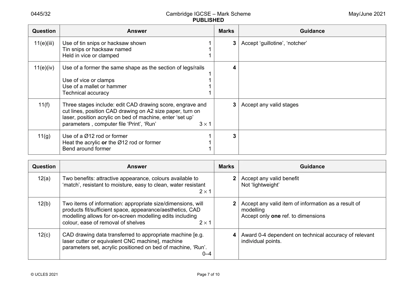
Mark scheme: 11(a) Two reasons: hardwearing, attractive, finishes well, tough, durable, long lasting, resistant to scratches 2 × 1 2 Not ‘easy to work with’ Not ‘can be used outdoors’ or ‘weather resistant’ 11(b)(i) Wider boards are not available, hardwood boards have limited width 500 mm wide boards are more expensive 1 Candidates giving ‘warping’ or ‘cupping’ in 11(b)(i) can be awarded 1 mark but do not accept a repeated answer in (b)(ii) 11(b)(ii) Boards arranged with alternating positions for end grain to provide stability 1 Without the arrangement the whole table top would ‘cup’, prevents splitting, prevents deforming over time 1 2 Candidates giving ‘warping’ or ‘cupping’ in 11(b)(i) can be awarded 1 mark but do not accept a repeated answer in (b)(ii) 11(c) Movement of solid wood occurs across the grain 1 Slots allow the screw to move as the wood expands or contracts 1 2 Award 1 mark for ‘ease of alignment of top to rails’ 11(d) (i) Grooves provide space for glue inside the drilled hole, allows excess glue/air to escape, provides better grip 1 (ii) Chamfer allows for easier entry into drilled hole 1 2 11(e)(i) Two marking out tools: scriber, try square, steel rule, metre rule, ruler, odd leg calipers, engineers/marking blue 2 × 1 2 Not ‘centre punch’ 11(e)(ii) To guide the tip of the drill, to prevent tip of drill ‘wandering’, to provide an accurately positioned hole 1 Question Answer Marks Guidance 11(e)(iii) Use of tin snips or hacksaw shown 1 Tin snips or hacksaw named 1 Held in vice or clamped 1 3 Accept ‘guillotine’, ‘notcher’ 11(e)(iv) Use of a former the same shape as the section of legs/rails 1 Use of vice or clamps 1 Use of a mallet or hammer 1 Technical accuracy 1 4 11(f) Three stages include: edit CAD drawing score, engrave and cut lines, position CAD drawing on A2 size paper, turn on laser, position acrylic on bed of machine, enter ‘set up’ parameters , computer file ‘Print’, ‘Run’ 3 × 1 3 Accept any valid stages 11(g) Use of a Ø12 rod or former 1 Heat the acrylic or the Ø12 rod or former 1 Bend around former 1 3
Q12 · A storage unit with adjustable shelves that will be used in a bathroom
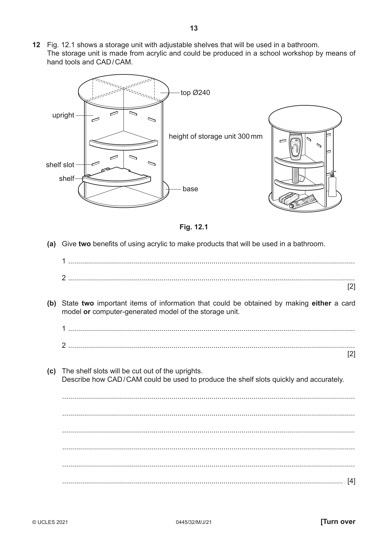
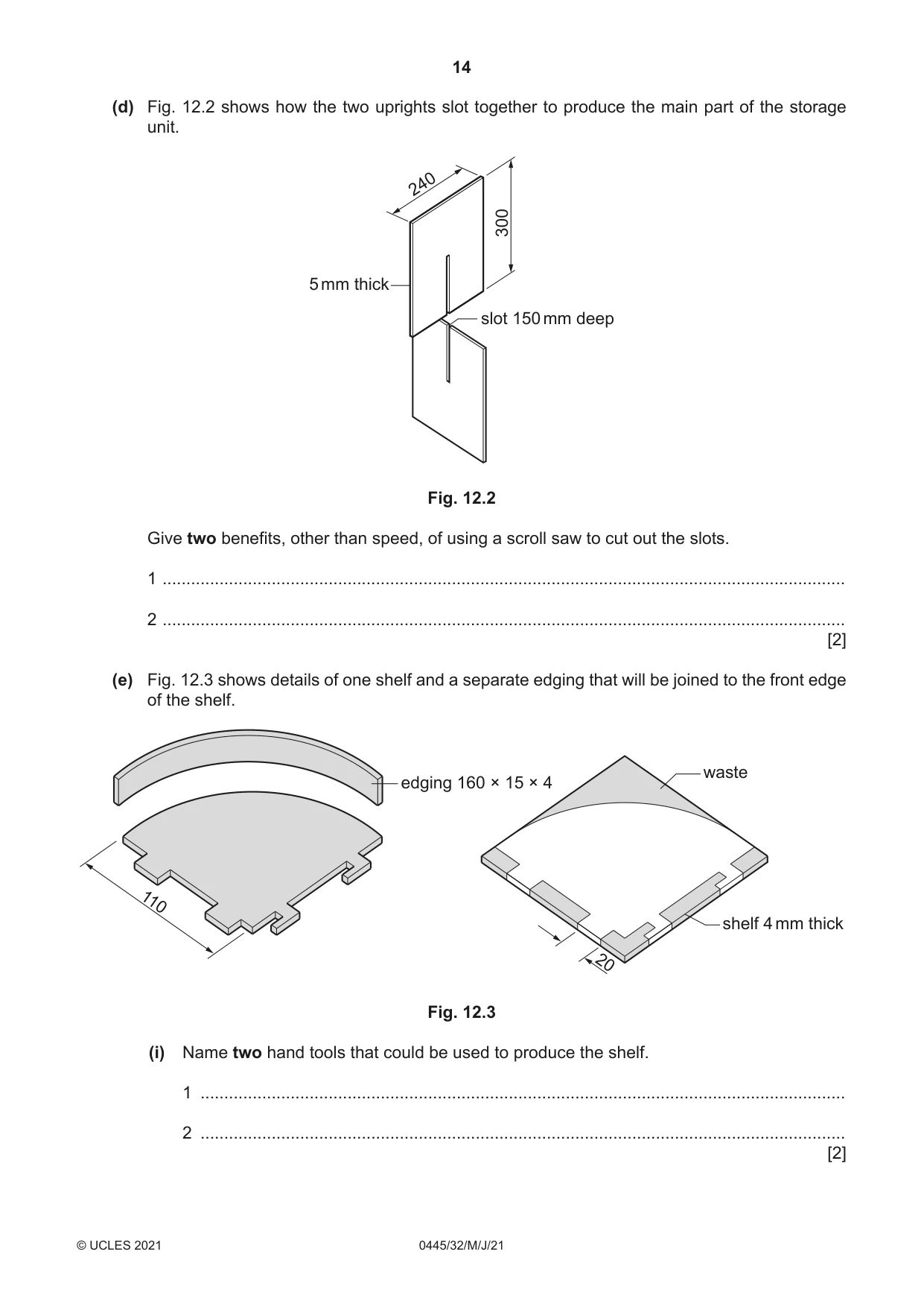
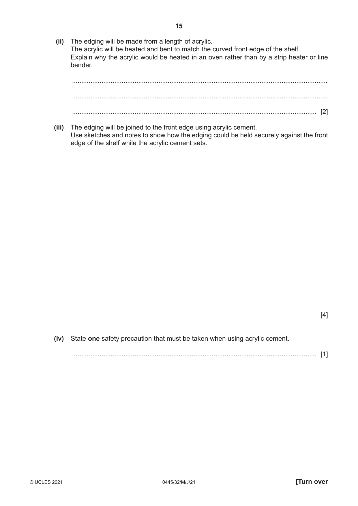
12 Fig. 12.1 shows a storage unit with adjustable shelves that will be used in a bathroom. The storage unit is made from acrylic and could be produced in a school workshop by means of hand tools and CAD / CAM. top Ø240 upright height of storage unit 300 mm shelf slot shelf base Fig. 12.1 (a) Give two benefits of using acrylic to make products that will be used in a bathroom. 1 ................................................................................................................................................ 2 ................................................................................................................................................ [2] (b) State two important items of information that could be obtained by making either a card model or computer-generated model of the storage unit. 1 ................................................................................................................................................ 2 ................................................................................................................................................ [2] (c) The shelf slots will be cut out of the uprights. Describe how CAD / CAM could be used to produce the shelf slots quickly and accurately. ................................................................................................................................................... ................................................................................................................................................... ................................................................................................................................................... ................................................................................................................................................... ................................................................................................................................................... ............................................................................................................................................. [4] (d) Fig. 12.2 shows how the two uprights slot together to produce the main part of the storage unit. 240 300 5 mm thick slot 150 mm deep Fig. 12.2 Give two benefits, other than speed, of using a scroll saw to cut out the slots. 1 ................................................................................................................................................ 2 ................................................................................................................................................ [2] (e) Fig. 12.3 shows details of one shelf and a separate edging that will be joined to the front edge of the shelf. waste edging 160 × 15 × 4 110 shelf 4 mm thick 20 Fig. 12.3 (i) Name two hand tools that could be used to produce the shelf. 1 ........................................................................................................................................ 2 ........................................................................................................................................ [2] (ii) The edging will be made from a length of acrylic. The acrylic will be heated and bent to match the curved front edge of the shelf. Explain why the acrylic would be heated in an oven rather than by a strip heater or line bender. ........................................................................................................................................... ........................................................................................................................................... ..................................................................................................................................... [2] (iii) The edging will be joined to the front edge using acrylic cement. Use sketches and notes to show how the edging could be held securely against the front edge of the shelf while the acrylic cement sets. [4] (iv) State one safety precaution that must be taken when using acrylic cement. ..................................................................................................................................... [1] (f) The items stored in the unit could be made easier to access if the unit could be made to rotate. Use sketches and notes to show how an additional base could be used to make the storage unit rotate. Give details of the materials and constructions used. [6]
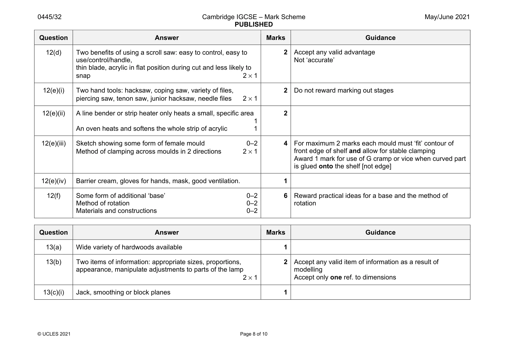
Mark scheme: 12(a) Two benefits: attractive appearance, colours available to ‘match’, resistant to moisture, easy to clean, water resistant 2 × 1 2 Accept any valid benefit Not ‘lightweight’ 12(b) Two items of information: appropriate size/dimensions, will products fit/sufficient space, appearance/aesthetics, CAD modelling allows for on-screen modelling edits including colour, ease of removal of shelves 2 × 1 2 Accept any valid item of information as a result of modelling Accept only one ref. to dimensions 12(c) CAD drawing data transferred to appropriate machine [e.g. laser cutter or equivalent CNC machine], machine parameters set, acrylic positioned on bed of machine, ‘Run’. 0–4 4 Award 0-4 dependent on technical accuracy of relevant individual points. Question Answer Marks Guidance 12(d) Two benefits of using a scroll saw: easy to control, easy to use/control/handle, thin blade, acrylic in flat position during cut and less likely to snap 2 × 1 2 Accept any valid advantage Not ‘accurate’ 12(e)(i) Two hand tools: hacksaw, coping saw, variety of files, piercing saw, tenon saw, junior hacksaw, needle files 2 × 1 2 Do not reward marking out stages 12(e)(ii) A line bender or strip heater only heats a small, specific area 1 An oven heats and softens the whole strip of acrylic 1 2 12(e)(iii) Sketch showing some form of female mould 0–2 Method of clamping across moulds in 2 directions 2 × 1 4 For maximum 2 marks each mould must ‘fit’ contour of front edge of shelf and allow for stable clamping Award 1 mark for use of G cramp or vice when curved part is glued onto the shelf [not edge] 12(e)(iv) Barrier cream, gloves for hands, mask, good ventilation. 1 12(f) Some form of additional ‘base’ 0–2 Method of rotation 0–2 Materials and constructions 0–2 6 Reward practical ideas for a base and the method of rotation
Q13 · An incomplete design for a novelty adjustable lamp made from hardwood
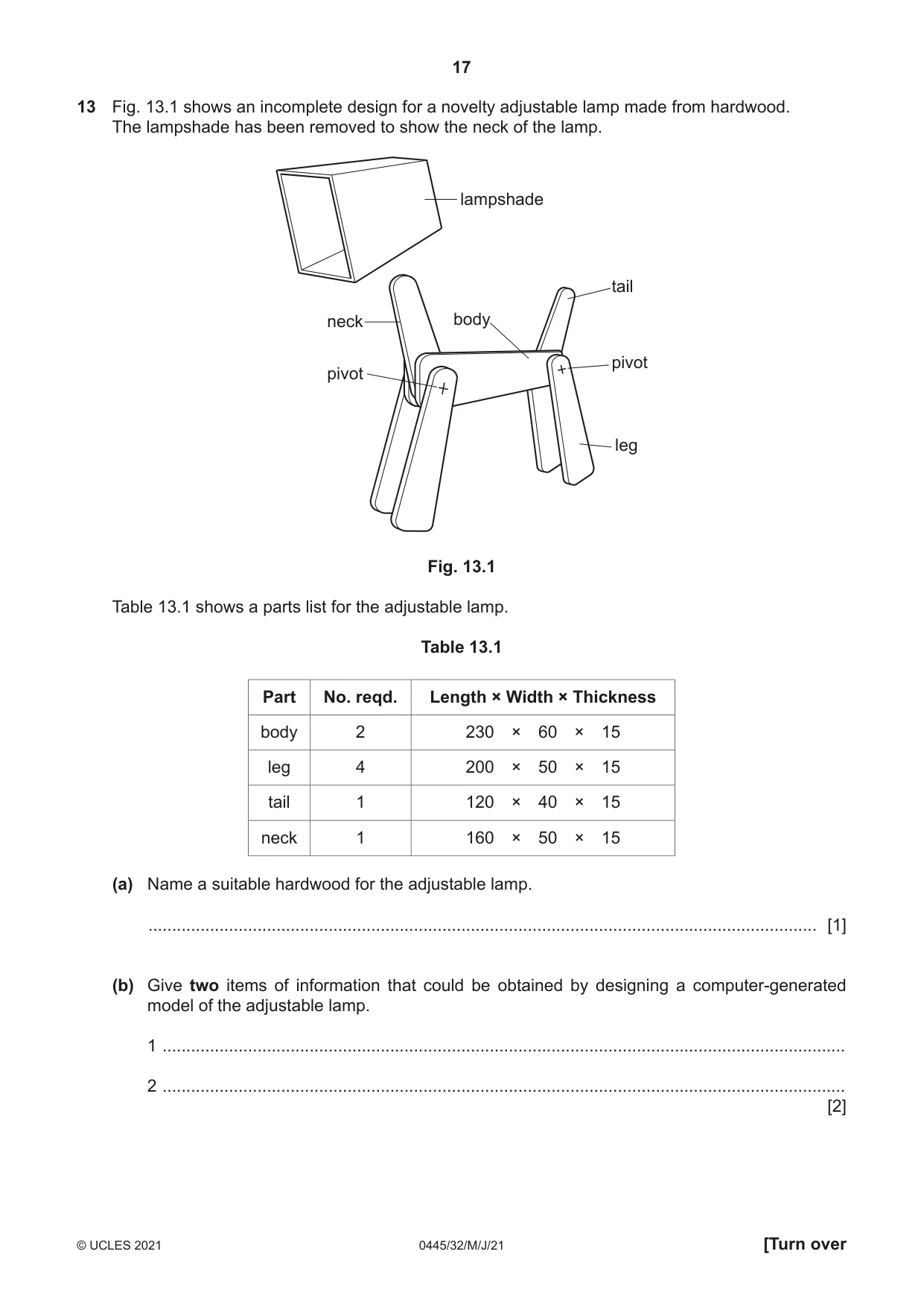
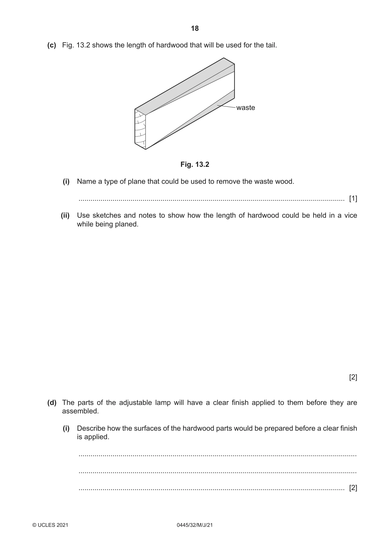
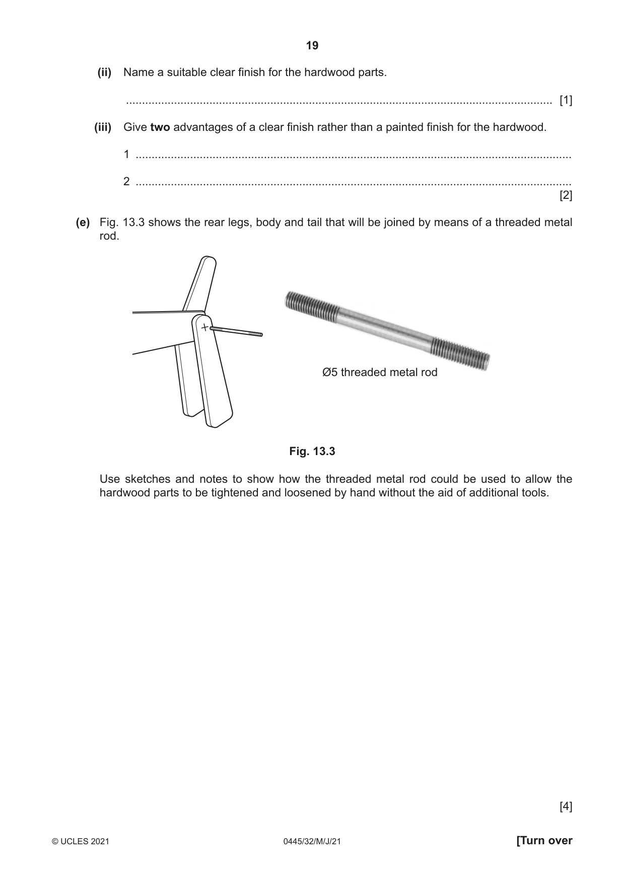
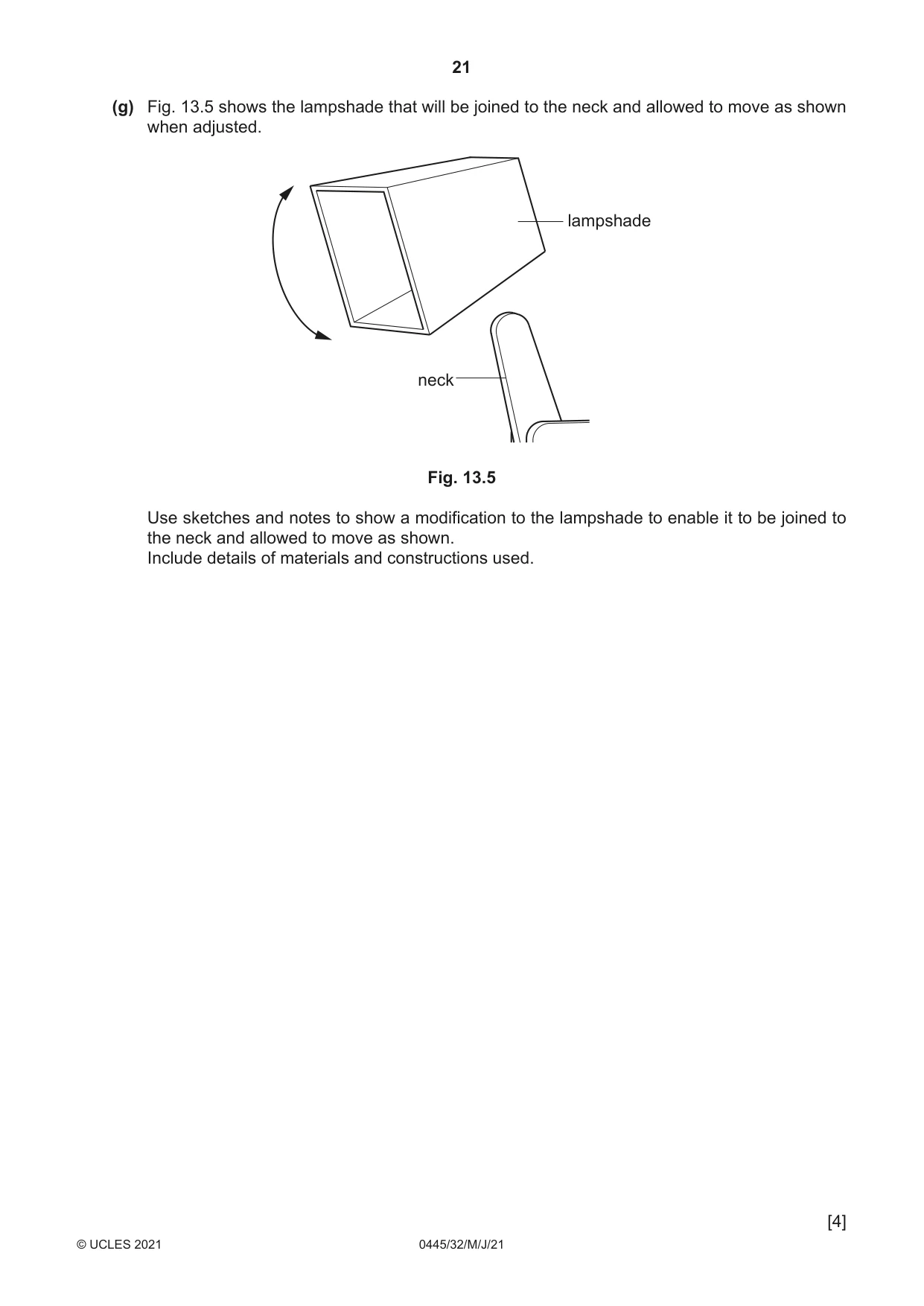
13 Fig. 13.1 shows an incomplete design for a novelty adjustable lamp made from hardwood. The lampshade has been removed to show the neck of the lamp. lampshade tail neck body pivot pivot leg Fig. 13.1 Table 13.1 shows a parts list for the adjustable lamp. Table 13.1 Part No. reqd. Length × Width × Thickness body 2 230 × 60 × 15 leg 4 200 × 50 × 15 tail 1 120 × 40 × 15 neck 1 160 × 50 × 15 (a) Name a suitable hardwood for the adjustable lamp. ............................................................................................................................................. [1] (b) Give two items of information that could be obtained by designing a computer-generated model of the adjustable lamp. 1 ................................................................................................................................................ 2 ................................................................................................................................................ [2] (c) Fig. 13.2 shows the length of hardwood that will be used for the tail. waste Fig. 13.2 (i) Name a type of plane that could be used to remove the waste wood. ..................................................................................................................................... [1] (ii) Use sketches and notes to show how the length of hardwood could be held in a vice while being planed. [2] (d) The parts of the adjustable lamp will have a clear finish applied to them before they are assembled. (i) Describe how the surfaces of the hardwood parts would be prepared before a clear finish is applied. ........................................................................................................................................... ........................................................................................................................................... ..................................................................................................................................... [2] (ii) Name a suitable clear finish for the hardwood parts. ..................................................................................................................................... [1] (iii) Give two advantages of a clear finish rather than a painted finish for the hardwood. 1 ........................................................................................................................................ 2 ........................................................................................................................................ [2] (e) Fig. 13.3 shows the rear legs, body and tail that will be joined by means of a threaded metal rod. Ø5 threaded metal rod Fig. 13.3 Use sketches and notes to show how the threaded metal rod could be used to allow the hardwood parts to be tightened and loosened by hand without the aid of additional tools. [4]
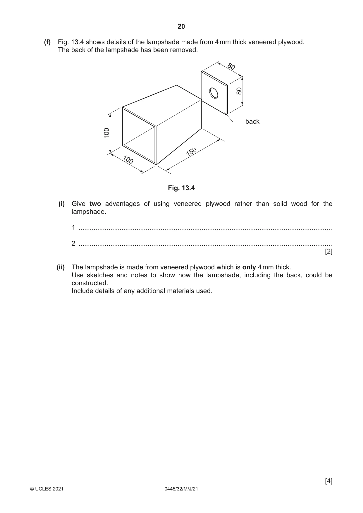
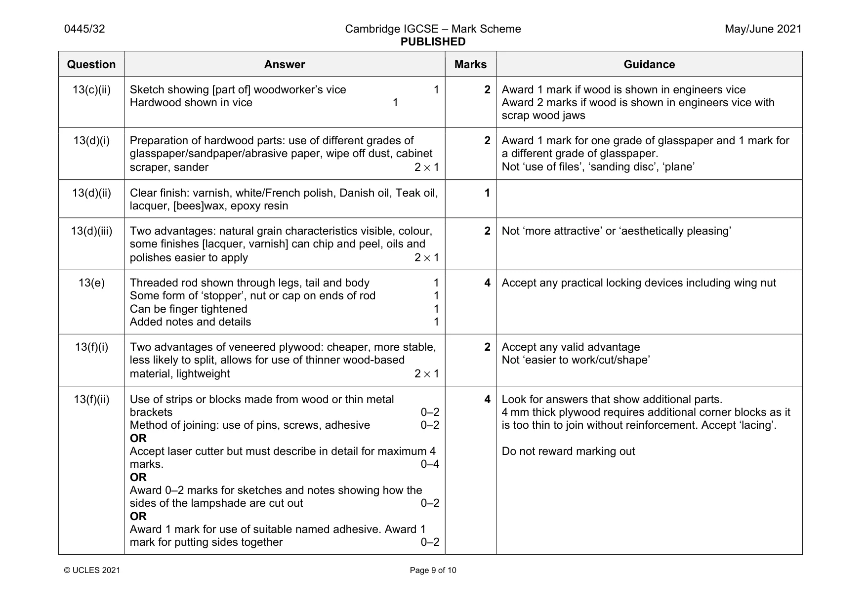
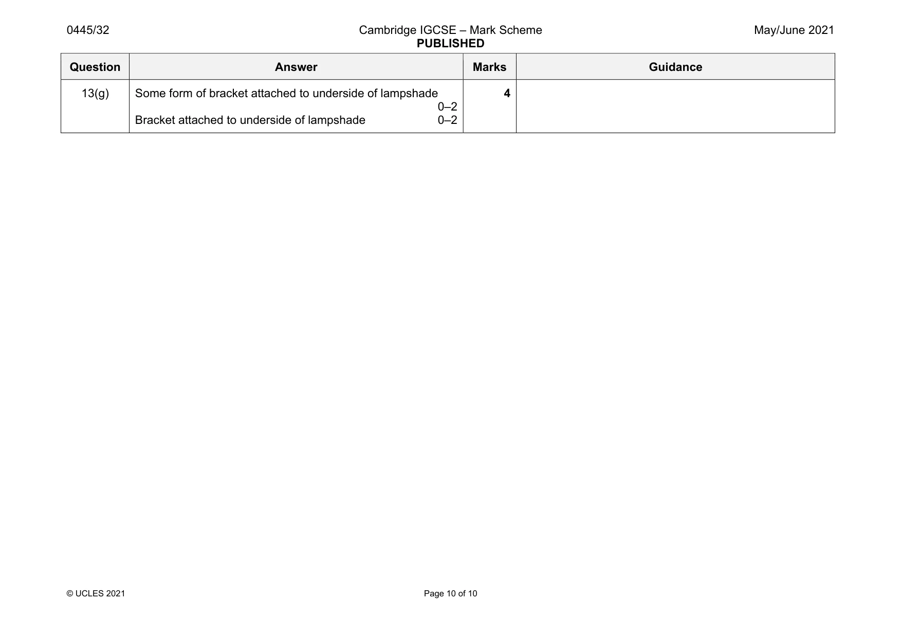
Mark scheme: 13(a) Wide variety of hardwoods available 1 13(b) Two items of information: appropriate sizes, proportions, appearance, manipulate adjustments to parts of the lamp 2 × 1 2 Accept any valid item of information as a result of modelling Accept only one ref. to dimensions 13(c)(i) Jack, smoothing or block planes 1 Question Answer Marks Guidance 13(c)(ii) Sketch showing [part of] woodworker’s vice 1 Hardwood shown in vice 1 2 Award 1 mark if wood is shown in engineers vice Award 2 marks if wood is shown in engineers vice with scrap wood jaws 13(d)(i) Preparation of hardwood parts: use of different grades of glasspaper/sandpaper/abrasive paper, wipe off dust, cabinet scraper, sander 2 × 1 2 Award 1 mark for one grade of glasspaper and 1 mark for a different grade of glasspaper. Not ‘use of files’, ‘sanding disc’, ‘plane’ 13(d)(ii) Clear finish: varnish, white/French polish, Danish oil, Teak oil, lacquer, [bees]wax, epoxy resin 1 13(d)(iii) Two advantages: natural grain characteristics visible, colour, some finishes [lacquer, varnish] can chip and peel, oils and polishes easier to apply 2 × 1 2 Not ‘more attractive’ or ‘aesthetically pleasing’ 13(e) Threaded rod shown through legs, tail and body 1 Some form of ‘stopper’, nut or cap on ends of rod 1 Can be finger tightened 1 Added notes and details 1 4 Accept any practical locking devices including wing nut 13(f)(i) Two advantages of veneered plywood: cheaper, more stable, less likely to split, allows for use of thinner wood-based material, lightweight 2 × 1 2 Accept any valid advantage Not ‘easier to work/cut/shape’ 13(f)(ii) Use of strips or blocks made from wood or thin metal brackets 0–2 Method of joining: use of pins, screws, adhesive 0–2 OR Accept laser cutter but must describe in detail for maximum 4 marks. 0–4 OR Award 0–2 marks for sketches and notes showing how the sides of the lampshade are cut out 0–2 OR Award 1 mark for use of suitable named adhesive. Award 1 mark for putting sides together 0–2 4 Look for answers that show additional parts. 4 mm thick plywood requires additional corner blocks as it is too thin to join without reinforcement. Accept ‘lacing’. Do not reward marking out Question Answer Marks Guidance 13(g) Some form of bracket attached to underside of lampshade 0–2 Bracket attached to underside of lampshade 0–2 4
What was in this paper
The subtopics covered by these 13 questions, and how many questions each got. Open one in a new tab to see every Cambridge question on it.
What you needed in this session
Cambridge’s own grade thresholds for 2021 May/June, Paper 3 · Variant 2. A higher threshold means an easier paper — the bar moves with how the cohort did.