Cambridge IGCSE Design and Technology 0445 — 2021 May/June Paper 3 · Variant 3
0445/33/M/J/21 · 13 questions · 50 marks · ≈56 min
The question paper and its mark scheme, free to read here and free to download. This is Cambridge’s own paper, exactly as it was sat.
Question paper20 pages
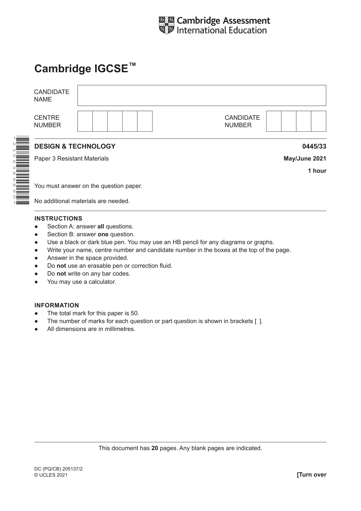

Mark scheme10 pages
Answers below. Sit the paper first if you are practising.
Questions as text
Question 1
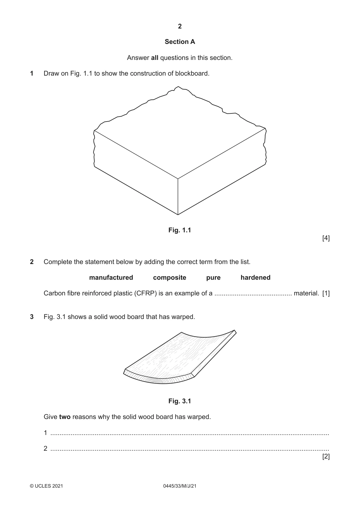
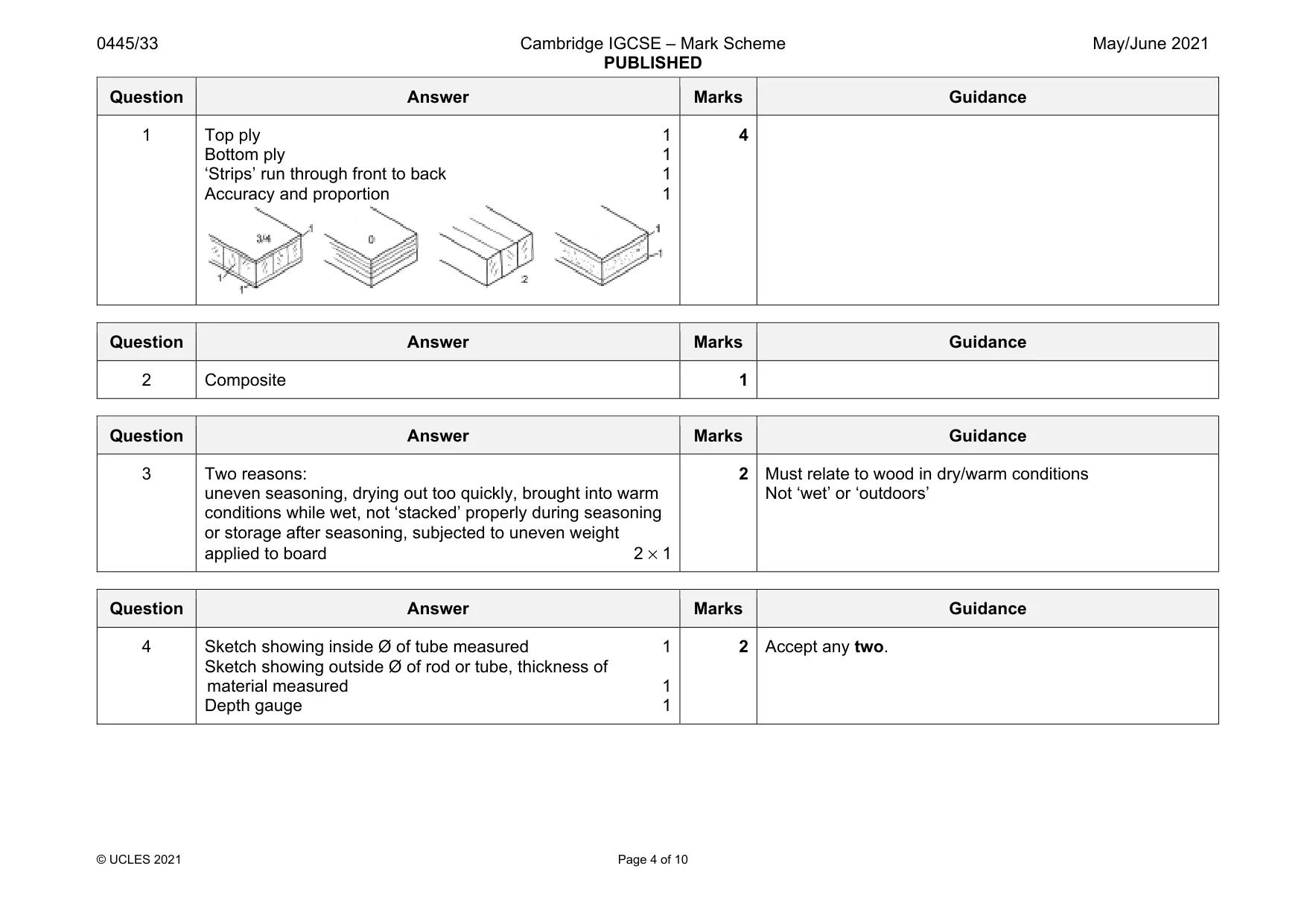
1 Draw on Fig. 1.1 to show the construction of blockboard. Fig. 1.1 [4]
Mark scheme: 1 Top ply 1 Bottom ply 1 ‘Strips’ run through front to back 1 Accuracy and proportion 1 4
Q2 · Complete the statement below by adding the correct term from the list
2 Complete the statement below by adding the correct term from the list. manufactured composite pure hardened Carbon fibre reinforced plastic (CFRP) is an example of a .......................................... material. [1]
Mark scheme: 2 Composite 1
Q3 · A solid wood board that has warped
3 Fig. 3.1 shows a solid wood board that has warped. Fig. 3.1 Give two reasons why the solid wood board has warped. 1 ....................................................................................................................................................... 2 ....................................................................................................................................................... [2]
Mark scheme: 3 Two reasons: uneven seasoning, drying out too quickly, brought into warm conditions while wet, not ‘stacked’ properly during seasoning or storage after seasoning, subjected to uneven weight applied to board 2 × 1 2 Must relate to wood in dry/warm conditions Not ‘wet’ or ‘outdoors’
Question 4
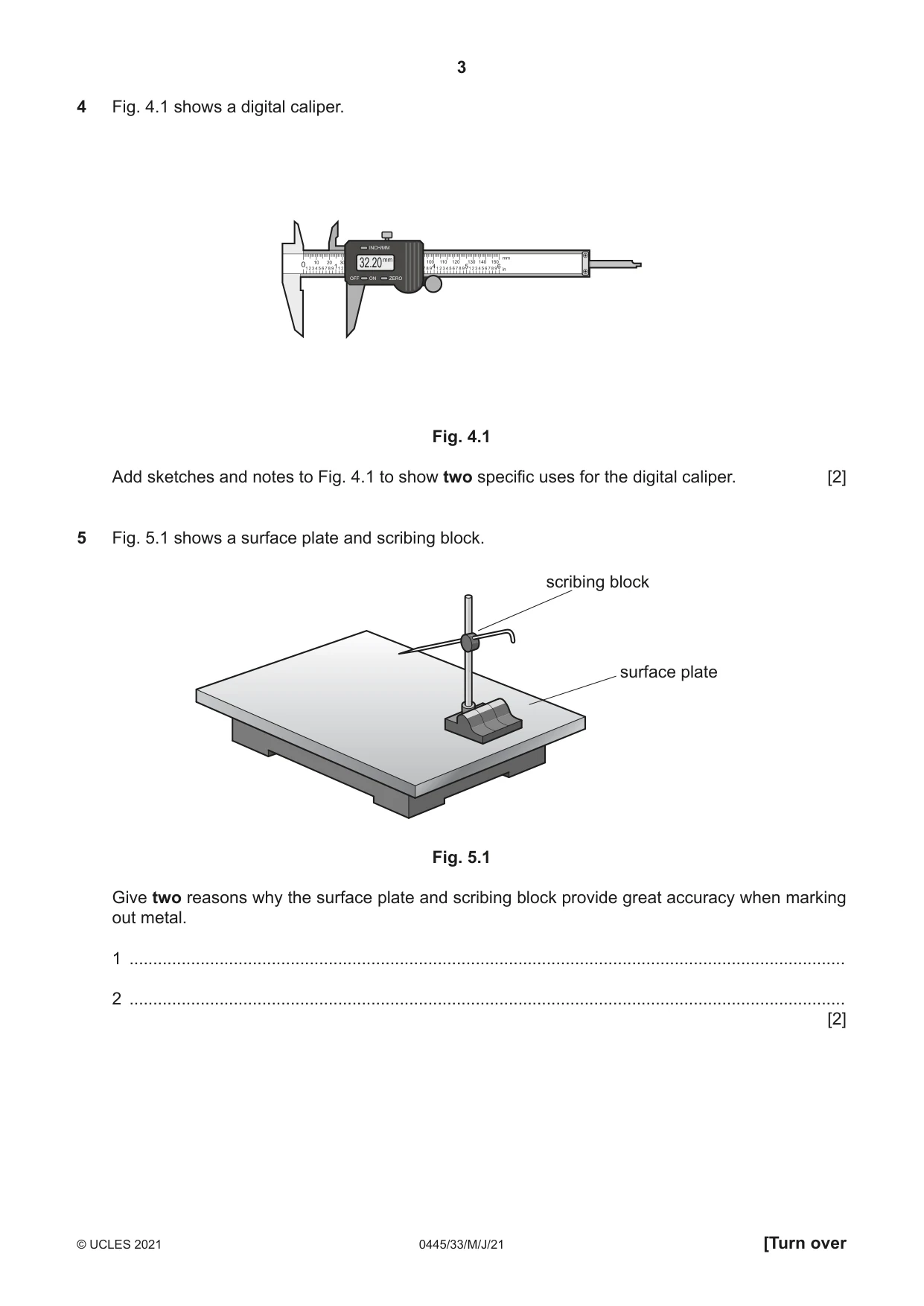
4 Fig. 4.1 shows a digital caliper. Fig. 4.1 Add sketches and notes to Fig. 4.1 to show two specific uses for the digital caliper. [2]
Mark scheme: 4 Sketch showing inside Ø of tube measured 1 Sketch showing outside Ø of rod or tube, thickness of material measured 1 Depth gauge 1 2 Accept any two.
Q5 · A surface plate and scribing block
5 Fig. 5.1 shows a surface plate and scribing block. scribing block surface plate Fig. 5.1 Give two reasons why the surface plate and scribing block provide great accuracy when marking out metal. 1 ....................................................................................................................................................... 2 ....................................................................................................................................................... [2]
Mark scheme: 5 Two reasons: surface plate and base of gauge machined to high specification, Provide a true surface from which to mark out, repetitive accuracy possible, parallel lines can be drawn, heights tested, fine adjustments can be made 2 × 1 Scribing block fixed position
Q6 · Complete the statement below by adding the correct term from the list
6 (a) Complete the statement below by adding the correct term from the list. polystyrene polypropylene polythene polyester Glass-reinforced plastic (GRP) is produced by laminating layers of glass-fibre mat with .......................................... resin. [1] (b) Some car bodies are made from glass-reinforced plastic (GRP). Give two advantages of using GRP rather than steel for car bodies. 1 ................................................................................................................................................ 2 ................................................................................................................................................ [2]
Mark scheme: 6(a) Polyester 1 6(b) Two advantages: lightweight, corrosion resistant, easily formed, excellent strength-weight ratio, easily repaired, inherent colour, weather resistant 2 × 1 2 Not ‘cheaper’, ‘impact resistant’, ‘tough’, ‘strong’, ‘easier to work’, easier to make ‘durable’
Q7 · An incomplete drawing of a hasp and staple fitting
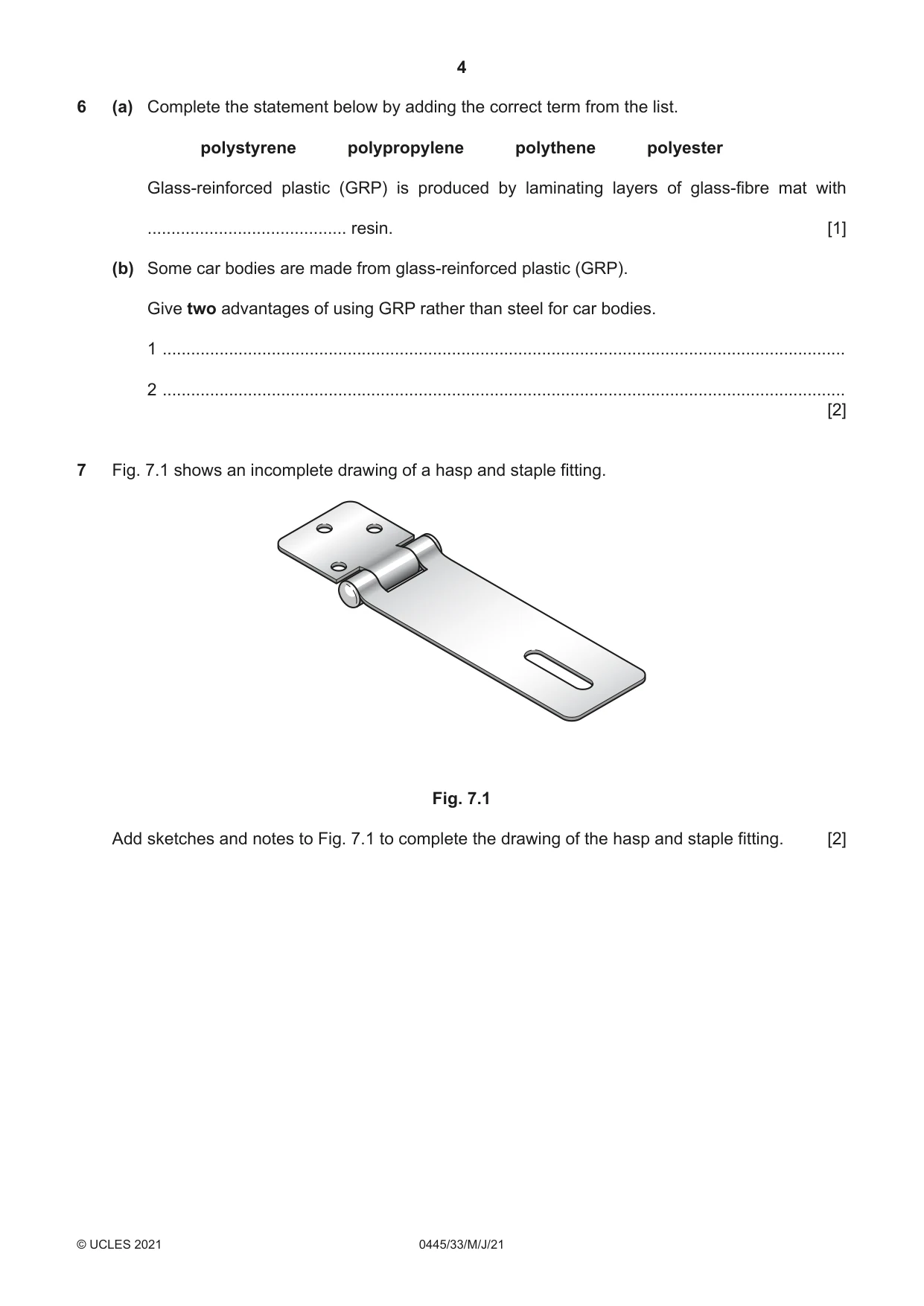
7 Fig. 7.1 shows an incomplete drawing of a hasp and staple fitting. Fig. 7.1 Add sketches and notes to Fig. 7.1 to complete the drawing of the hasp and staple fitting. [2]
Mark scheme: 7 Staple shown inserted through slot 1 Staple includes bottom plate/base 1 2
Q8 · A chair leg made from a length of hardwood 100 mm wide × 20 mm thick
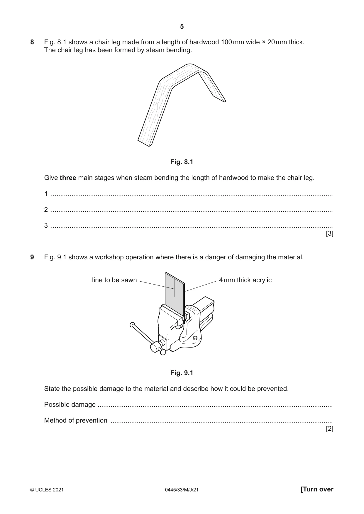
8 Fig. 8.1 shows a chair leg made from a length of hardwood 100 mm wide × 20 mm thick. The chair leg has been formed by steam bending. Fig. 8.1 Give three main stages when steam bending the length of hardwood to make the chair leg. 1 ....................................................................................................................................................... 2 ....................................................................................................................................................... 3 ....................................................................................................................................................... [3]
Mark scheme: 8 Stages include: wood placed in sealed chest, chest filled with steam, wood absorbs hot steam, wood held around a former, clamped in position, allowed to dry before removing from chest 3 × 1 Must include clamping for maximum marks Do not accept ‘steam machine’
Q9 · A workshop operation where there is a danger of damaging the material
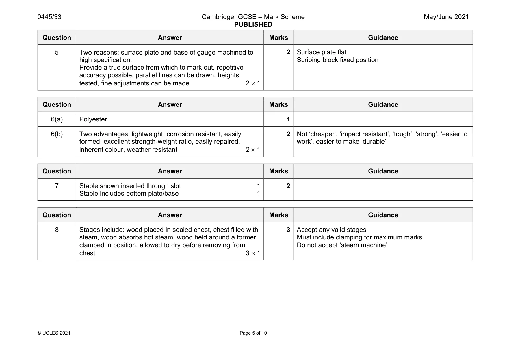
9 Fig. 9.1 shows a workshop operation where there is a danger of damaging the material. line to be sawn 4 mm thick acrylic Fig. 9.1 State the possible damage to the material and describe how it could be prevented. Possible damage .............................................................................................................................. Method of prevention ....................................................................................................................... [2]
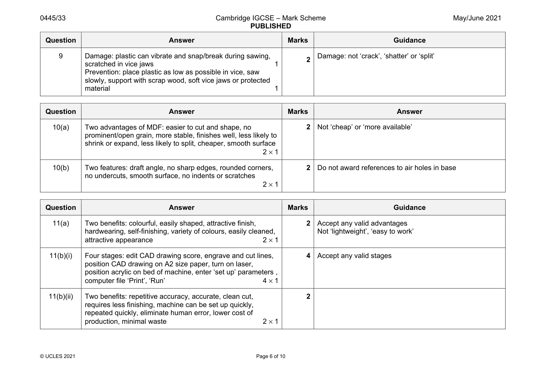
Mark scheme: 9 Damage: plastic can vibrate and snap/break during sawing, scratched in vice jaws 1 Prevention: place plastic as low as possible in vice, saw slowly, support with scrap wood, soft vice jaws or protected material 1 2 Damage: not ‘crack’, ‘shatter’ or ‘split’
Q10 · A wooden mould used to vacuum form a small tray
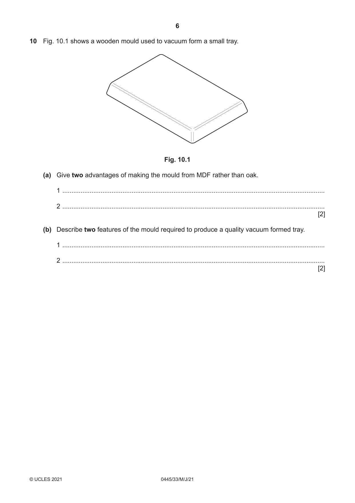
10 Fig. 10.1 shows a wooden mould used to vacuum form a small tray. Fig. 10.1 (a) Give two advantages of making the mould from MDF rather than oak. 1 ................................................................................................................................................ 2 ................................................................................................................................................ [2] (b) Describe two features of the mould required to produce a quality vacuum formed tray. 1 ................................................................................................................................................ 2 ................................................................................................................................................ [2]
Mark scheme: 10(a) Two advantages of MDF: easier to cut and shape, no prominent/open grain, more stable, finishes well, less likely to shrink or expand, less likely to split, cheaper, smooth surface 2 × 1 10(b) Two features: draft angle, no sharp edges, rounded corners, no undercuts, smooth surface, no indents or scratches 2 × 1 2 Do not award references to air holes in base
Q11 · Details of an incomplete design for an adjustable mirror made mainly from acrylic
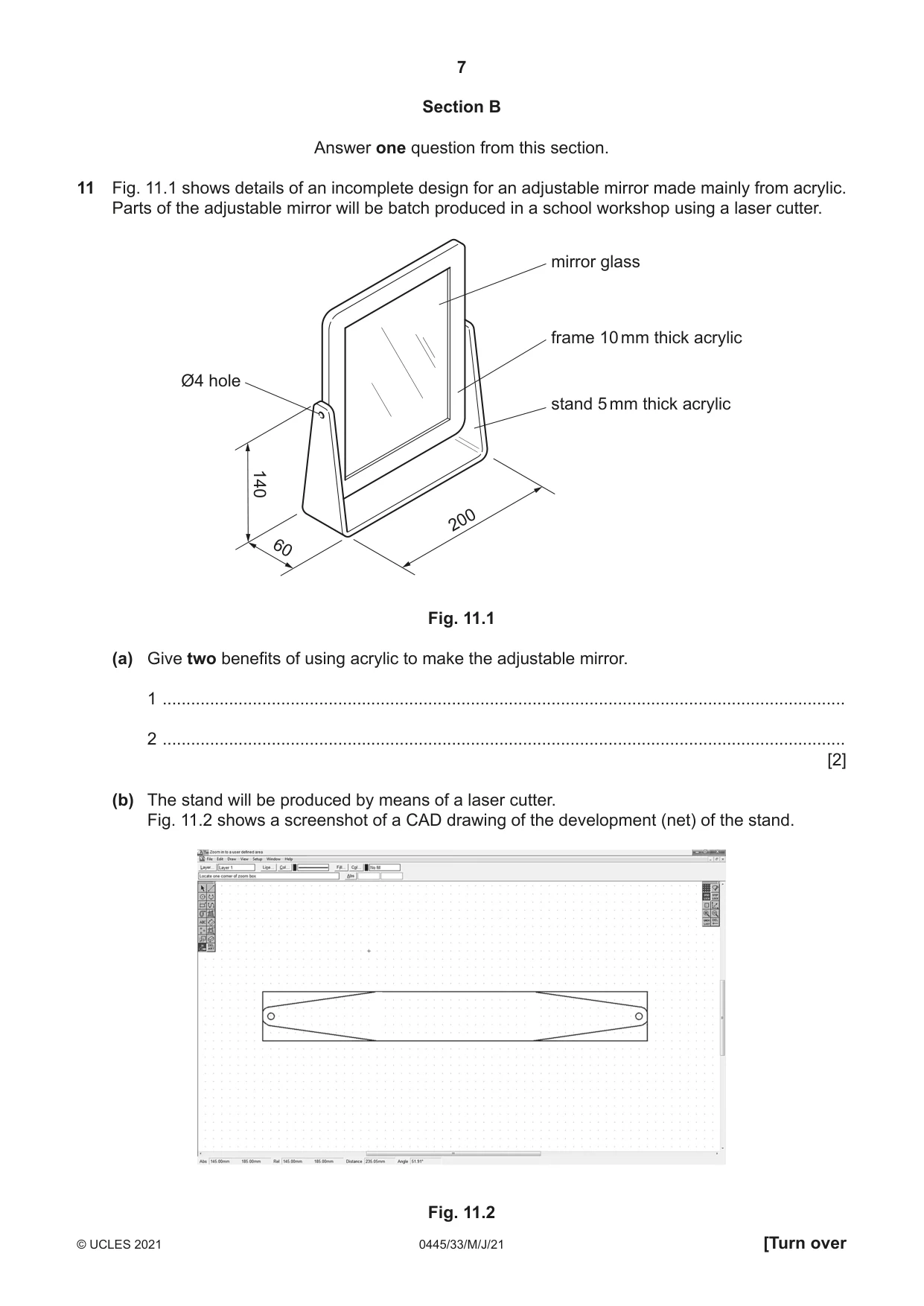
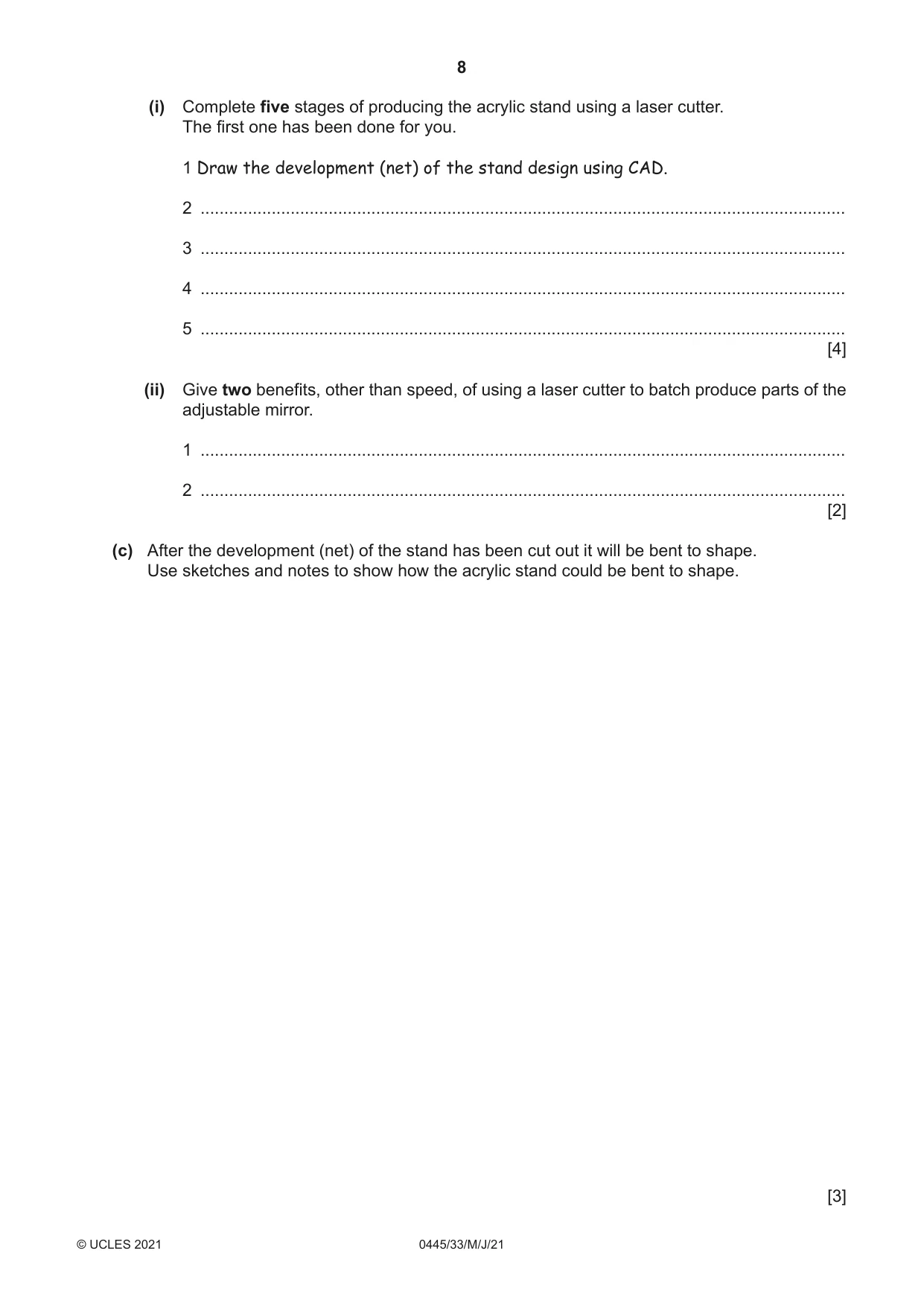
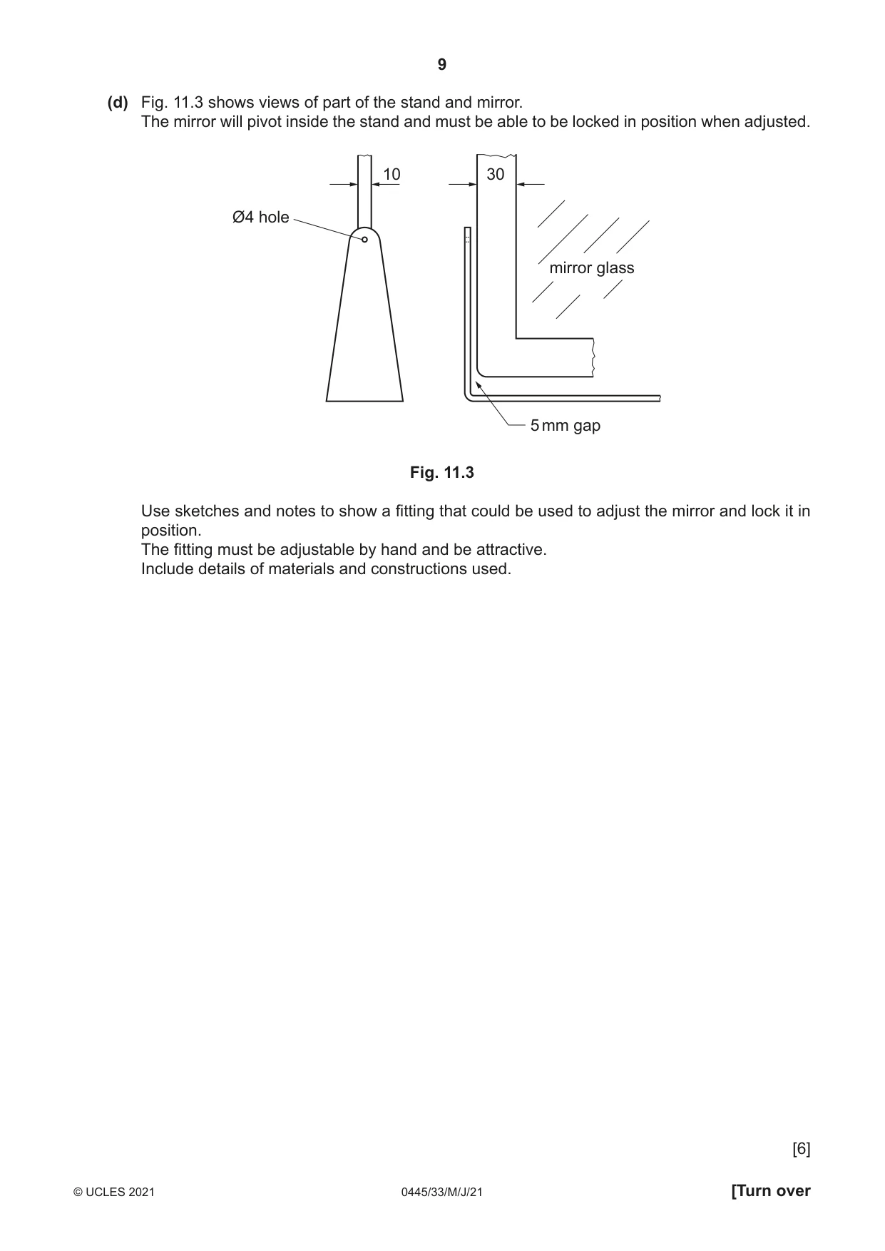
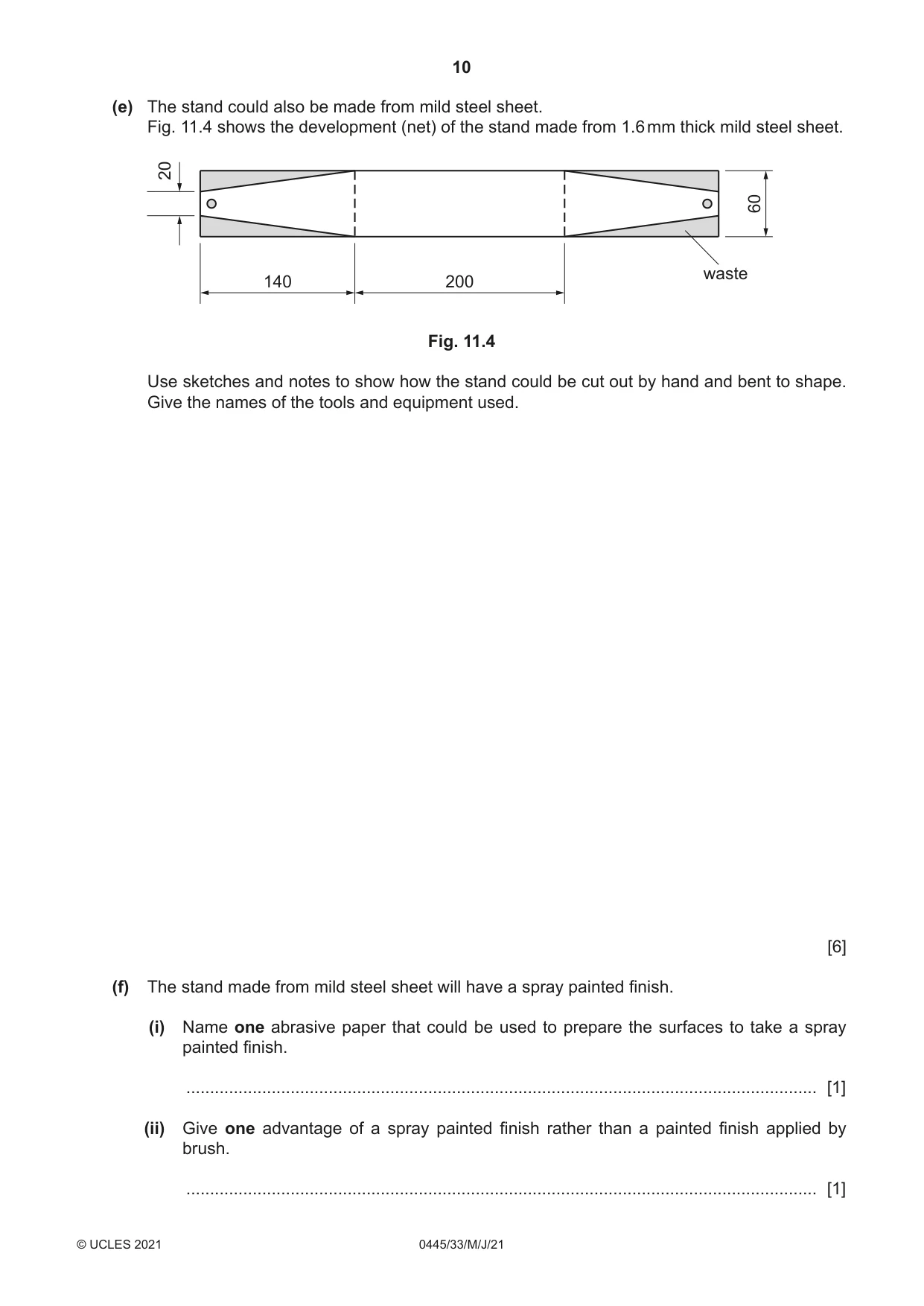
11 Fig. 11.1 shows details of an incomplete design for an adjustable mirror made mainly from acrylic. Parts of the adjustable mirror will be batch produced in a school workshop using a laser cutter. mirror glass frame 10 mm thick acrylic Ø4 hole stand 5 mm thick acrylic 140 200 60 Fig. 11.1 (a) Give two benefits of using acrylic to make the adjustable mirror. 1 ................................................................................................................................................ 2 ................................................................................................................................................ [2] (b) The stand will be produced by means of a laser cutter. Fig. 11.2 shows a screenshot of a CAD drawing of the development (net) of the stand. Fig. 11.2 (i) Complete five stages of producing the acrylic stand using a laser cutter. The first one has been done for you. 1 Draw the development (net) of the stand design using CAD. 2 ........................................................................................................................................ 3 ........................................................................................................................................ 4 ........................................................................................................................................ 5 ........................................................................................................................................ [4] (ii) Give two benefits, other than speed, of using a laser cutter to batch produce parts of the adjustable mirror. 1 ........................................................................................................................................ 2 ........................................................................................................................................ [2] (c) After the development (net) of the stand has been cut out it will be bent to shape. Use sketches and notes to show how the acrylic stand could be bent to shape. [3] (d) Fig. 11.3 shows views of part of the stand and mirror. The mirror will pivot inside the stand and must be able to be locked in position when adjusted. 10 30 Ø4 hole mirror glass 5 mm gap Fig. 11.3 Use sketches and notes to show a fitting that could be used to adjust the mirror and lock it in position. The fitting must be adjustable by hand and be attractive. Include details of materials and constructions used. [6] (e) The stand could also be made from mild steel sheet. Fig. 11.4 shows the development (net) of the stand made from 1.6 mm thick mild steel sheet. 20 60 waste 140 200 Fig. 11.4 Use sketches and notes to show how the stand could be cut out by hand and bent to shape. Give the names of the tools and equipment used. [6] (f) The stand made from mild steel sheet will have a spray painted finish. (i) Name one abrasive paper that could be used to prepare the surfaces to take a spray painted finish. ..................................................................................................................................... [1] (ii) Give one advantage of a spray painted finish rather than a painted finish applied by brush. ..................................................................................................................................... [1]
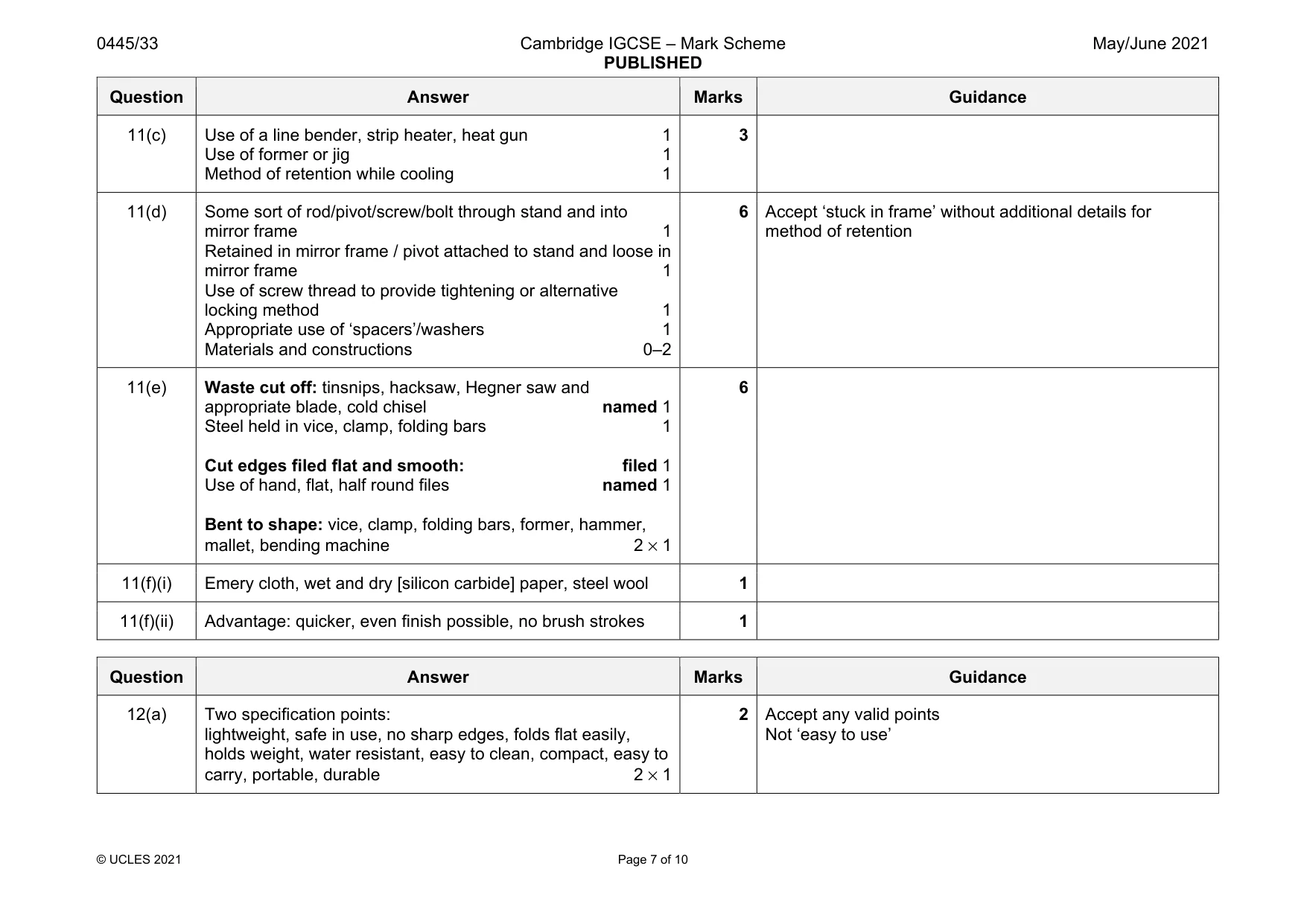
Mark scheme: 11(a) Two benefits: colourful, easily shaped, attractive finish, hardwearing, self-finishing, variety of colours, easily cleaned, attractive appearance 2 × 1 2 Accept any valid advantages Not ‘lightweight’, ‘easy to work’ 11(b)(i) Four stages: edit CAD drawing score, engrave and cut lines, position CAD drawing on A2 size paper, turn on laser, position acrylic on bed of machine, enter ‘set up’ parameters , computer file ‘Print’, ‘Run’ 4 × 1 4 Accept any valid stages 11(b)(ii) Two benefits: repetitive accuracy, accurate, clean cut, requires less finishing, machine can be set up quickly, repeated quickly, eliminate human error, lower cost of production, minimal waste 2 × 1 2 Question Answer Marks Guidance 11(c) Use of a line bender, strip heater, heat gun 1 Use of former or jig 1 Method of retention while cooling 1 3 11(d) Some sort of rod/pivot/screw/bolt through stand and into mirror frame 1 Retained in mirror frame / pivot attached to stand and loose in mirror frame 1 Use of screw thread to provide tightening or alternative locking method 1 Appropriate use of ‘spacers’/washers 1 Materials and constructions 0–2 6 Accept ‘stuck in frame’ without additional details for method of retention 11(e) Waste cut off: tinsnips, hacksaw, Hegner saw and appropriate blade, cold chisel named 1 Steel held in vice, clamp, folding bars 1 Cut edges filed flat and smooth: filed 1 Use of hand, flat, half round files named 1 Bent to shape: vice, clamp, folding bars, former, hammer, mallet, bending machine 2 × 1 6 11(f)(i) Emery cloth, wet and dry [silicon carbide] paper, steel wool 1 11(f)(ii) Advantage: quicker, even finish possible, no brush strokes 1
Q12 · A folding stool made from hardwood with a fabric seat
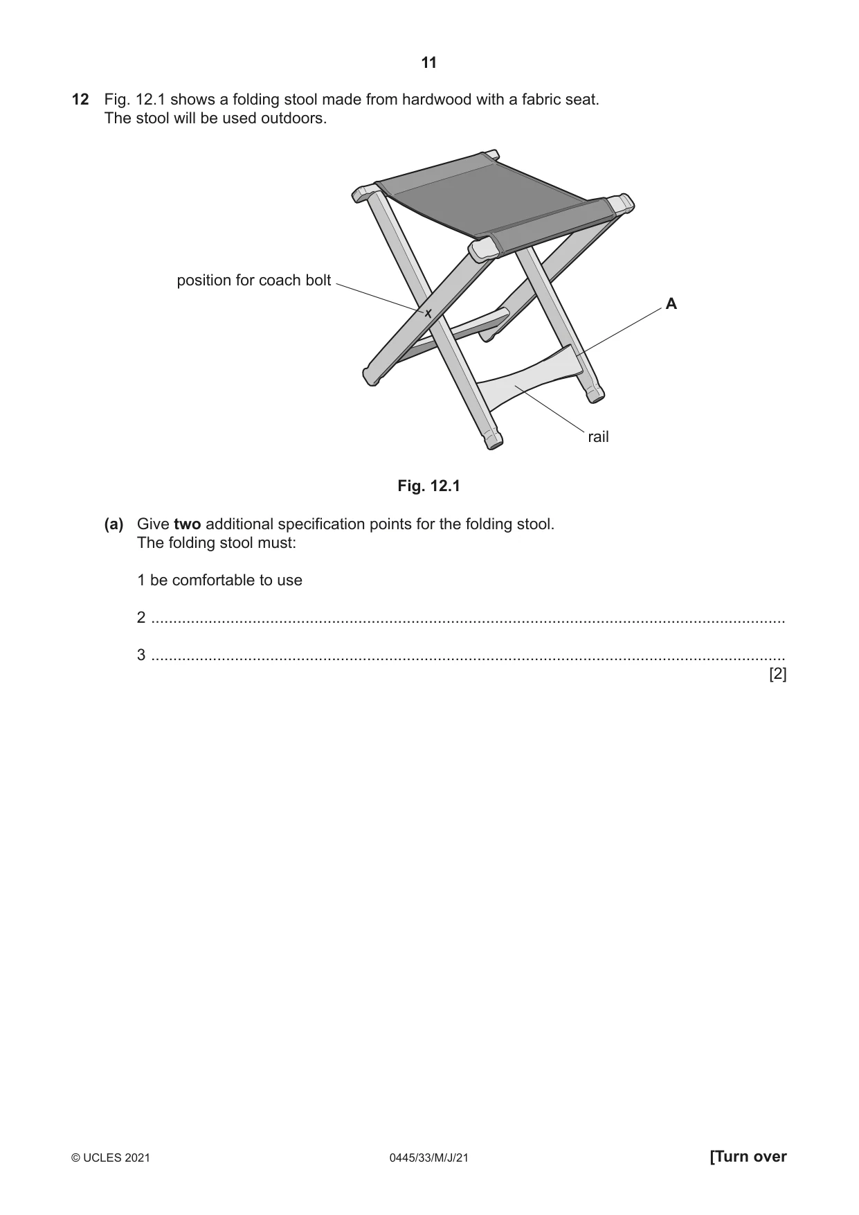
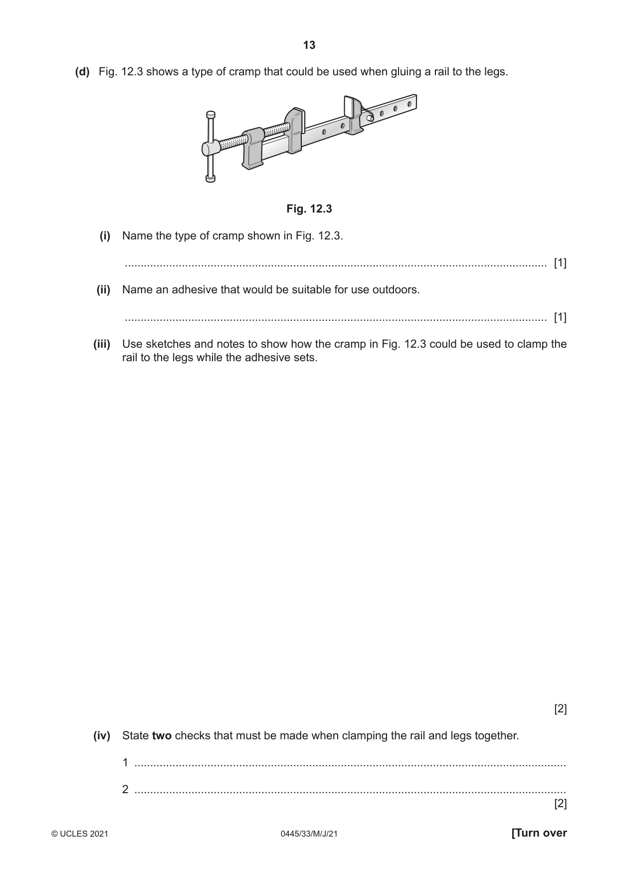
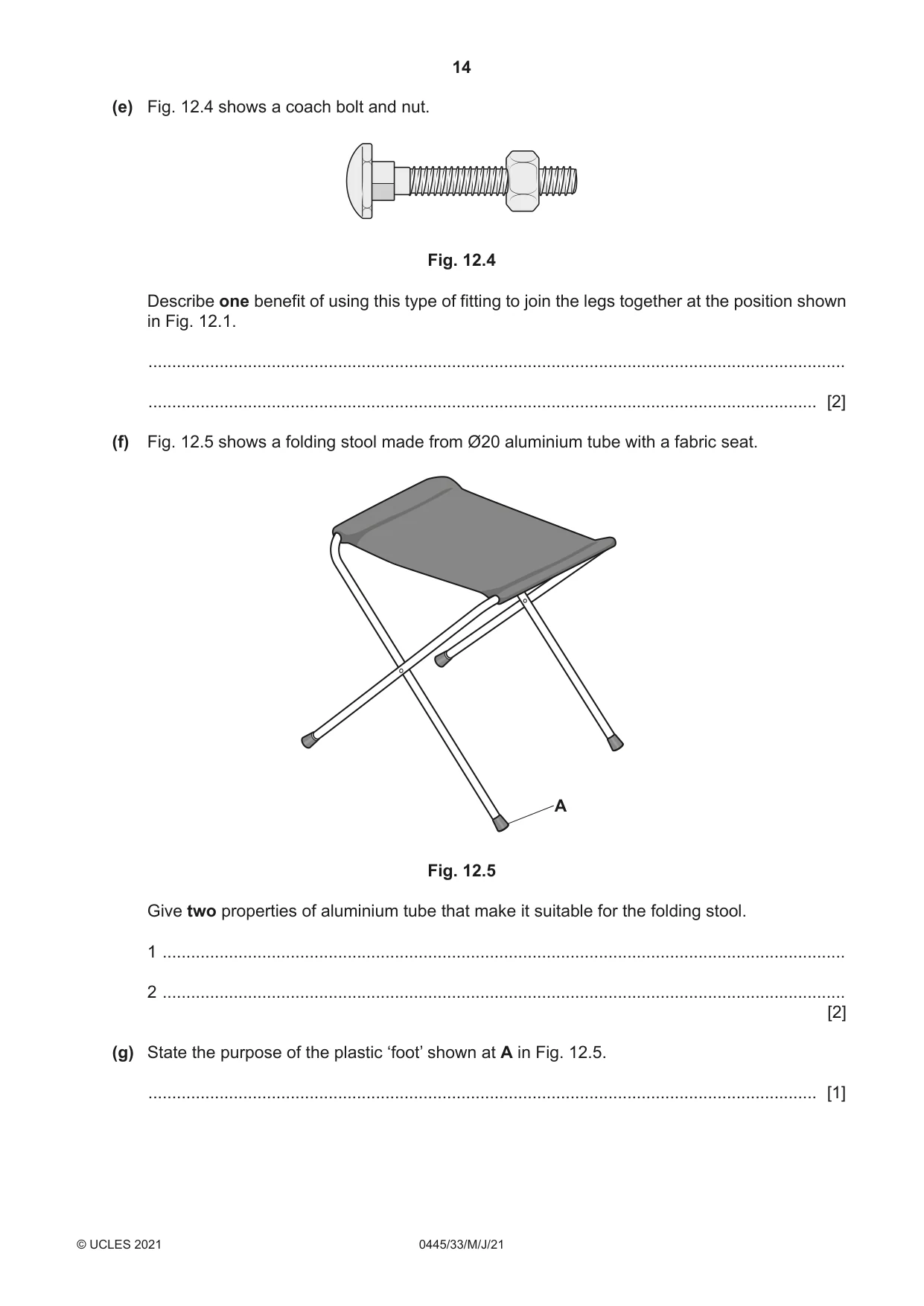
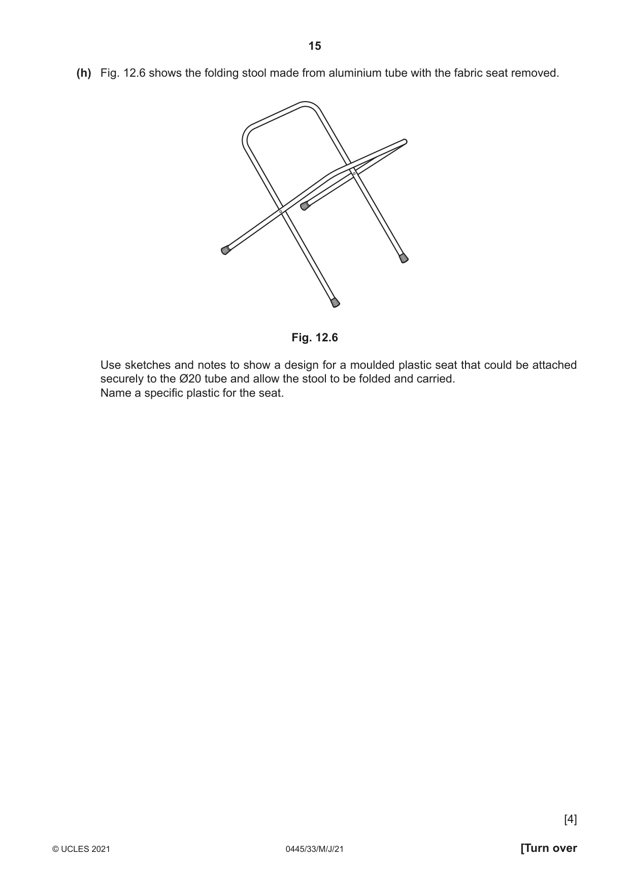
12 Fig. 12.1 shows a folding stool made from hardwood with a fabric seat. The stool will be used outdoors. position for coach bolt A rail Fig. 12.1 (a) Give two additional specification points for the folding stool. The folding stool must: 1 be comfortable to use 2 ................................................................................................................................................ 3 ................................................................................................................................................ [2] (b) Fig. 12.2 shows the shape of the rail marked out, ready to be cut out. waste 400 50 20 Fig. 12.2 Use sketches and notes to show how the curved shape could be produced. Show how the rail could be held securely while the shape is produced. Give the correct names of the tools and equipment used. [4] (c) Sketch and name a suitable construction that could be used to join the rail to the leg at A in Fig. 12.1. Name of construction ................................................................................................................ [4] (d) Fig. 12.3 shows a type of cramp that could be used when gluing a rail to the legs. Fig. 12.3 (i) Name the type of cramp shown in Fig. 12.3. ..................................................................................................................................... [1] (ii) Name an adhesive that would be suitable for use outdoors. ..................................................................................................................................... [1] (iii) Use sketches and notes to show how the cramp in Fig. 12.3 could be used to clamp the rail to the legs while the adhesive sets. [2] (iv) State two checks that must be made when clamping the rail and legs together. 1 ........................................................................................................................................ 2 ........................................................................................................................................ [2] (e) Fig. 12.4 shows a coach bolt and nut. Fig. 12.4 Describe one benefit of using this type of fitting to join the legs together at the position shown in Fig. 12.1. ................................................................................................................................................... ............................................................................................................................................. [2] (f) Fig. 12.5 shows a folding stool made from Ø20 aluminium tube with a fabric seat. A Fig. 12.5 Give two properties of aluminium tube that make it suitable for the folding stool. 1 ................................................................................................................................................ 2 ................................................................................................................................................ [2] (g) State the purpose of the plastic ‘foot’ shown at A in Fig. 12.5. ............................................................................................................................................. [1] (h) Fig. 12.6 shows the folding stool made from aluminium tube with the fabric seat removed. Fig. 12.6 Use sketches and notes to show a design for a moulded plastic seat that could be attached securely to the Ø20 tube and allow the stool to be folded and carried. Name a specific plastic for the seat. [4]
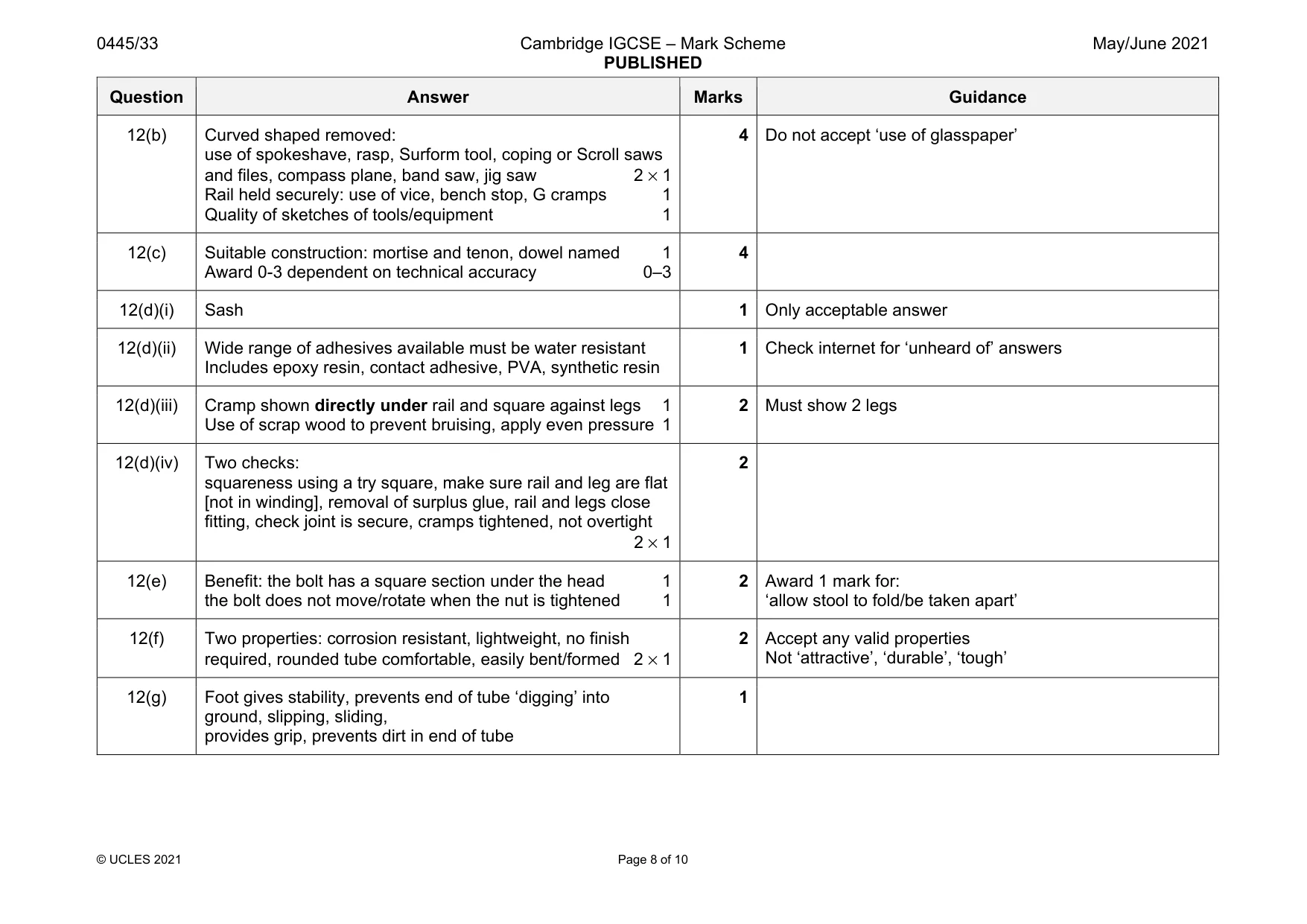
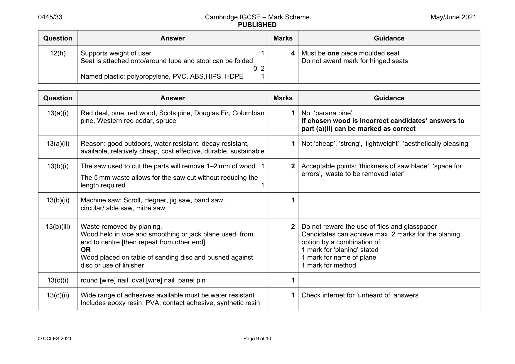
Mark scheme: 12(a) Two specification points: lightweight, safe in use, no sharp edges, folds flat easily, holds weight, water resistant, easy to clean, compact, easy to carry, portable, durable 2 × 1 2 Accept any valid points Not ‘easy to use’ Question Answer Marks Guidance 12(b) Curved shaped removed: use of spokeshave, rasp, Surform tool, coping or Scroll saws and files, compass plane, band saw, jig saw 2 × 1 Rail held securely: use of vice, bench stop, G cramps 1 Quality of sketches of tools/equipment 1 4 Do not accept ‘use of glasspaper’ 12(c) Suitable construction: mortise and tenon, dowel named 1 Award 0-3 dependent on technical accuracy 0–3 4 12(d)(i) Sash 1 Only acceptable answer 12(d)(ii) Wide range of adhesives available must be water resistant Includes epoxy resin, contact adhesive, PVA, synthetic resin 1 Check internet for ‘unheard of’ answers 12(d)(iii) Cramp shown directly under rail and square against legs 1 Use of scrap wood to prevent bruising, apply even pressure 1 2 Must show 2 legs 12(d)(iv) Two checks: squareness using a try square, make sure rail and leg are flat [not in winding], removal of surplus glue, rail and legs close fitting, check joint is secure, cramps tightened, not overtight 2 × 1 2 12(e) Benefit: the bolt has a square section under the head 1 the bolt does not move/rotate when the nut is tightened 1 2 Award 1 mark for: ‘allow stool to fold/be taken apart’ 12(f) Two properties: corrosion resistant, lightweight, no finish required, rounded tube comfortable, easily bent/formed 2 × 1 2 Accept any valid properties Not ‘attractive’, ‘durable’, ‘tough’ 12(g) Foot gives stability, prevents end of tube ‘digging’ into ground, slipping, sliding, provides grip, prevents dirt in end of tube 1 Question Answer Marks Guidance 12(h) Supports weight of user 1 Seat is attached onto/around tube and stool can be folded 0–2 Named plastic: polypropylene, PVC, ABS,HIPS, HDPE 1 4 Must be one piece moulded seat Do not award mark for hinged seats
Q13 · A nesting box made from 15 mm thick softwood
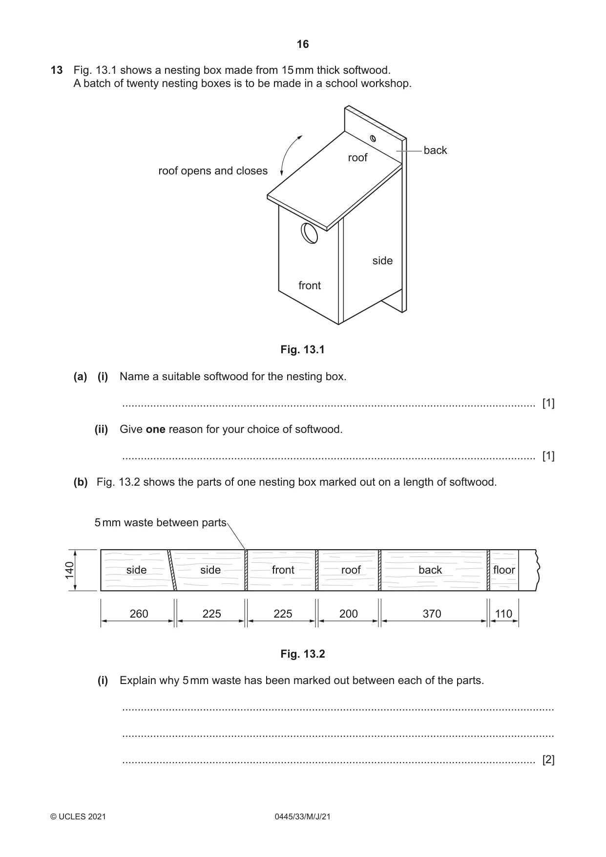
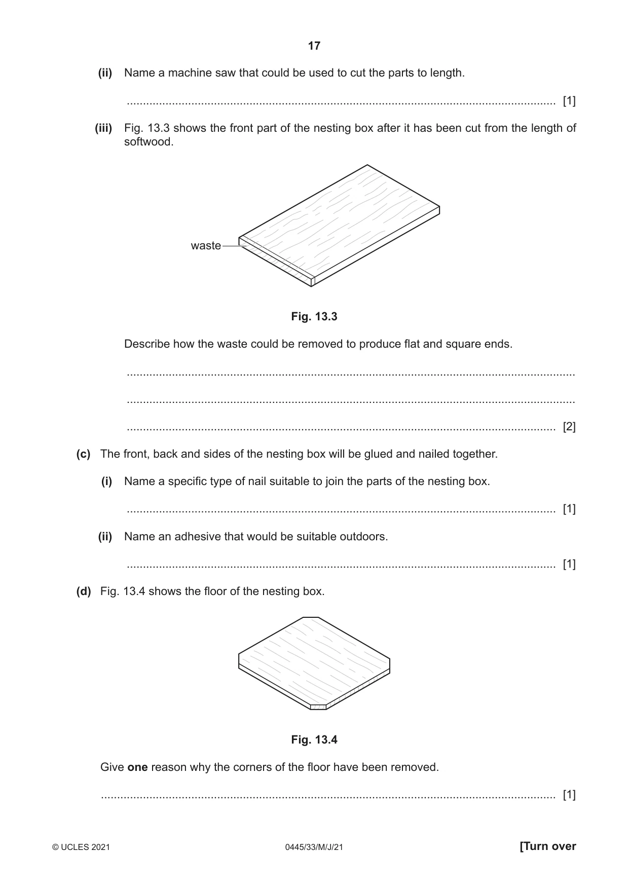
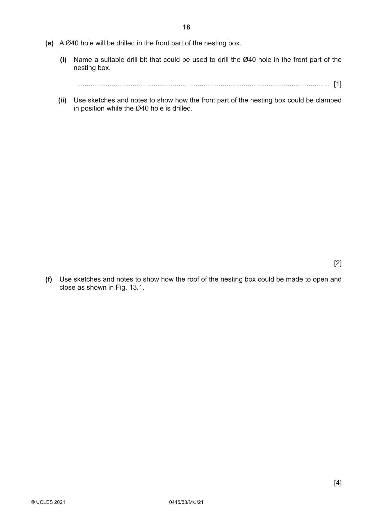
13 Fig. 13.1 shows a nesting box made from 15 mm thick softwood. A batch of twenty nesting boxes is to be made in a school workshop. back roof roof opens and closes side front Fig. 13.1 (a) (i) Name a suitable softwood for the nesting box. ..................................................................................................................................... [1] (ii) Give one reason for your choice of softwood. ..................................................................................................................................... [1] (b) Fig. 13.2 shows the parts of one nesting box marked out on a length of softwood. 5 mm waste between parts 140 sideside sideside frontfront roofroof backback floorfloor 260 225 225 200 370 110 Fig. 13.2 (i) Explain why 5 mm waste has been marked out between each of the parts. ........................................................................................................................................... ........................................................................................................................................... ..................................................................................................................................... [2] (ii) Name a machine saw that could be used to cut the parts to length. ..................................................................................................................................... [1] (iii) Fig. 13.3 shows the front part of the nesting box after it has been cut from the length of softwood. waste Fig. 13.3 Describe how the waste could be removed to produce flat and square ends. ........................................................................................................................................... ........................................................................................................................................... ..................................................................................................................................... [2] (c) The front, back and sides of the nesting box will be glued and nailed together. (i) Name a specific type of nail suitable to join the parts of the nesting box. ..................................................................................................................................... [1] (ii) Name an adhesive that would be suitable outdoors. ..................................................................................................................................... [1] (d) Fig. 13.4 shows the floor of the nesting box. Fig. 13.4 Give one reason why the corners of the floor have been removed. ............................................................................................................................................. [1] (e) A Ø40 hole will be drilled in the front part of the nesting box. (i) Name a suitable drill bit that could be used to drill the Ø40 hole in the front part of the nesting box. ..................................................................................................................................... [1] (ii) Use sketches and notes to show how the front part of the nesting box could be clamped in position while the Ø40 hole is drilled. [2] (f) Use sketches and notes to show how the roof of the nesting box could be made to open and close as shown in Fig. 13.1. [4]
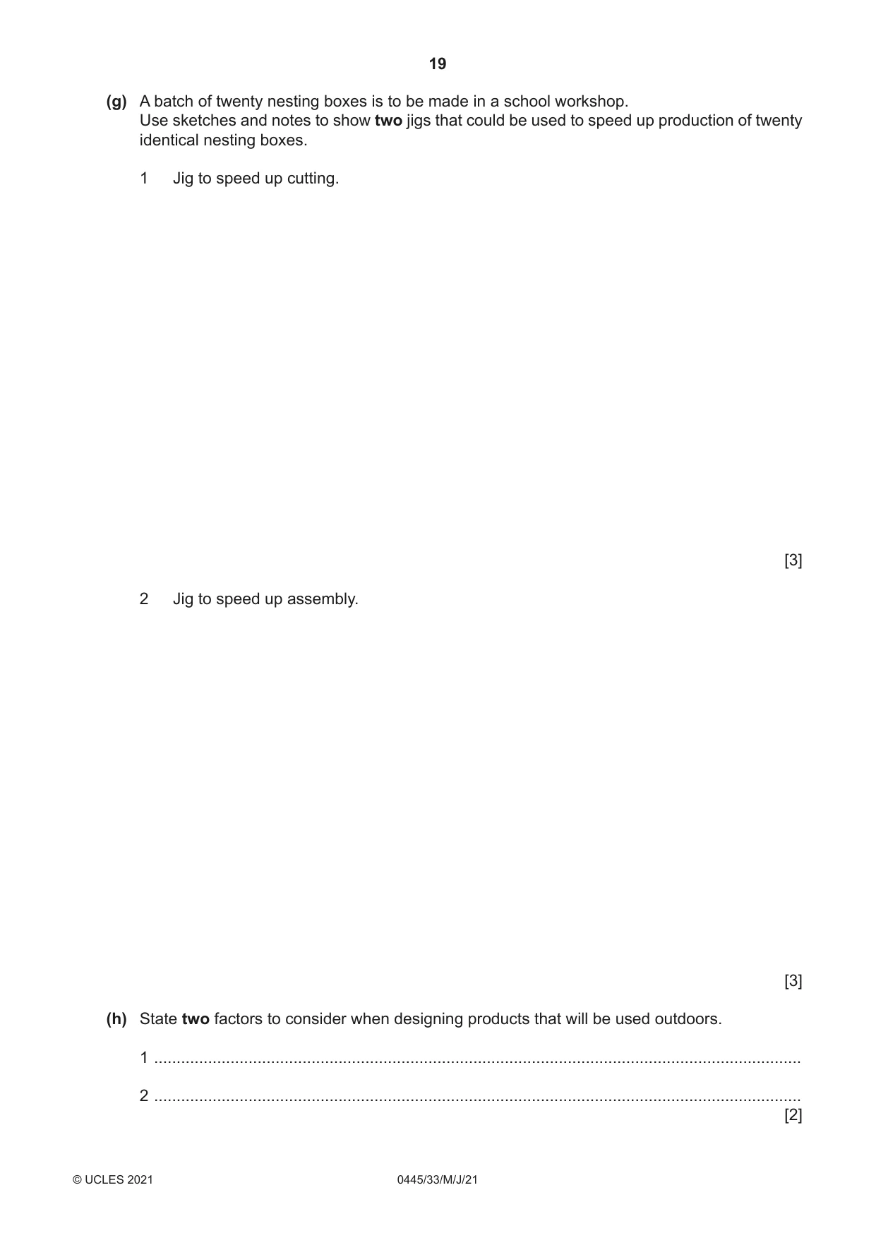
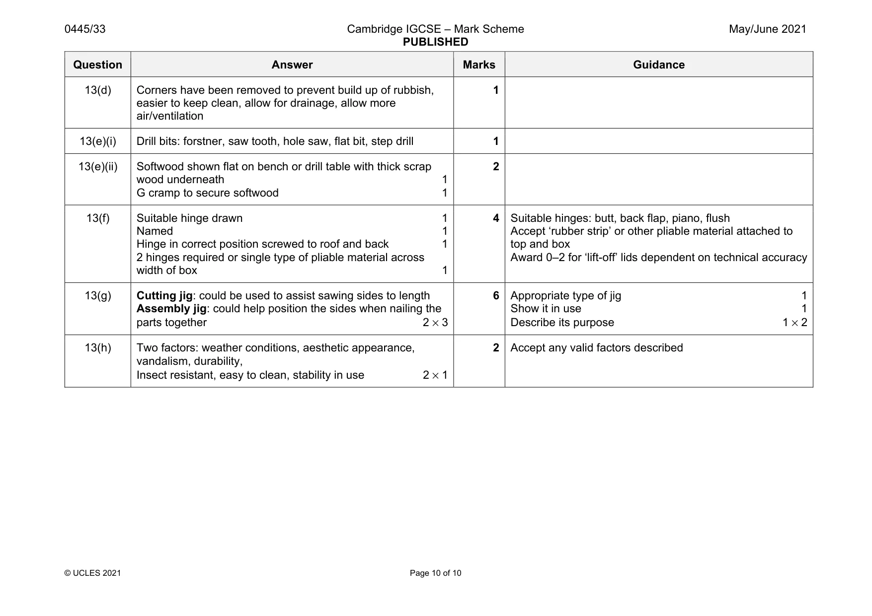
Mark scheme: 13(a)(i) Red deal, pine, red wood, Scots pine, Douglas Fir, Columbian pine, Western red cedar, spruce 1 Not ‘parana pine’ If chosen wood is incorrect candidates’ answers to part (a)(ii) can be marked as correct 13(a)(ii) Reason: good outdoors, water resistant, decay resistant, available, relatively cheap, cost effective, durable, sustainable 1 Not ‘cheap’, ‘strong’, ‘lightweight’, ‘aesthetically pleasing’ 13(b)(i) The saw used to cut the parts will remove 1–2 mm of wood 1 The 5 mm waste allows for the saw cut without reducing the length required 1 2 Acceptable points: ‘thickness of saw blade’, ‘space for errors’, ‘waste to be removed later’ 13(b)(ii) Machine saw: Scroll, Hegner, jig saw, band saw, circular/table saw, mitre saw 1 13(b)(iii) Waste removed by planing. Wood held in vice and smoothing or jack plane used, from end to centre [then repeat from other end] OR Wood placed on table of sanding disc and pushed against disc or use of linisher 2 Do not reward the use of files and glasspaper Candidates can achieve max. 2 marks for the planing option by a combination of: 1 mark for ‘planing’ stated 1 mark for name of plane 1 mark for method 13(c)(i) round [wire] nail oval [wire] nail panel pin 1 13(c)(ii) Wide range of adhesives available must be water resistant Includes epoxy resin, PVA, contact adhesive, synthetic resin 1 Check internet for ‘unheard of’ answers Question Answer Marks Guidance 13(d) Corners have been removed to prevent build up of rubbish, easier to keep clean, allow for drainage, allow more air/ventilation 1 13(e)(i) Drill bits: forstner, saw tooth, hole saw, flat bit, step drill 1 13(e)(ii) Softwood shown flat on bench or drill table with thick scrap wood underneath 1 G cramp to secure softwood 1 2 13(f) Suitable hinge drawn 1 Named 1 Hinge in correct position screwed to roof and back 1 2 hinges required or single type of pliable material across width of box 1 4 Suitable hinges: butt, back flap, piano, flush Accept ‘rubber strip’ or other pliable material attached to top and box Award 0–2 for ‘lift-off’ lids dependent on technical accuracy 13(g) Cutting jig: could be used to assist sawing sides to length Assembly jig: could help position the sides when nailing the parts together 2 × 3 6 Appropriate type of jig 1 Show it in use 1 Describe its purpose 1 × 2 13(h) Two factors: weather conditions, aesthetic appearance, vandalism, durability, Insect resistant, easy to clean, stability in use 2 × 1 2 Accept any valid factors described
What was in this paper
The subtopics covered by these 13 questions, and how many questions each got. Open one in a new tab to see every Cambridge question on it.
What you needed in this session
Cambridge’s own grade thresholds for 2021 May/June, Paper 3 · Variant 3. A higher threshold means an easier paper — the bar moves with how the cohort did.