Cambridge IGCSE Design and Technology 0445 — 2020 Oct/Nov Paper 3 · Variant 2
0445/32/O/N/20 · 13 questions · 50 marks · ≈56 min
The question paper and its mark scheme, free to read here and free to download. This is Cambridge’s own paper, exactly as it was sat.
Question paper24 pages
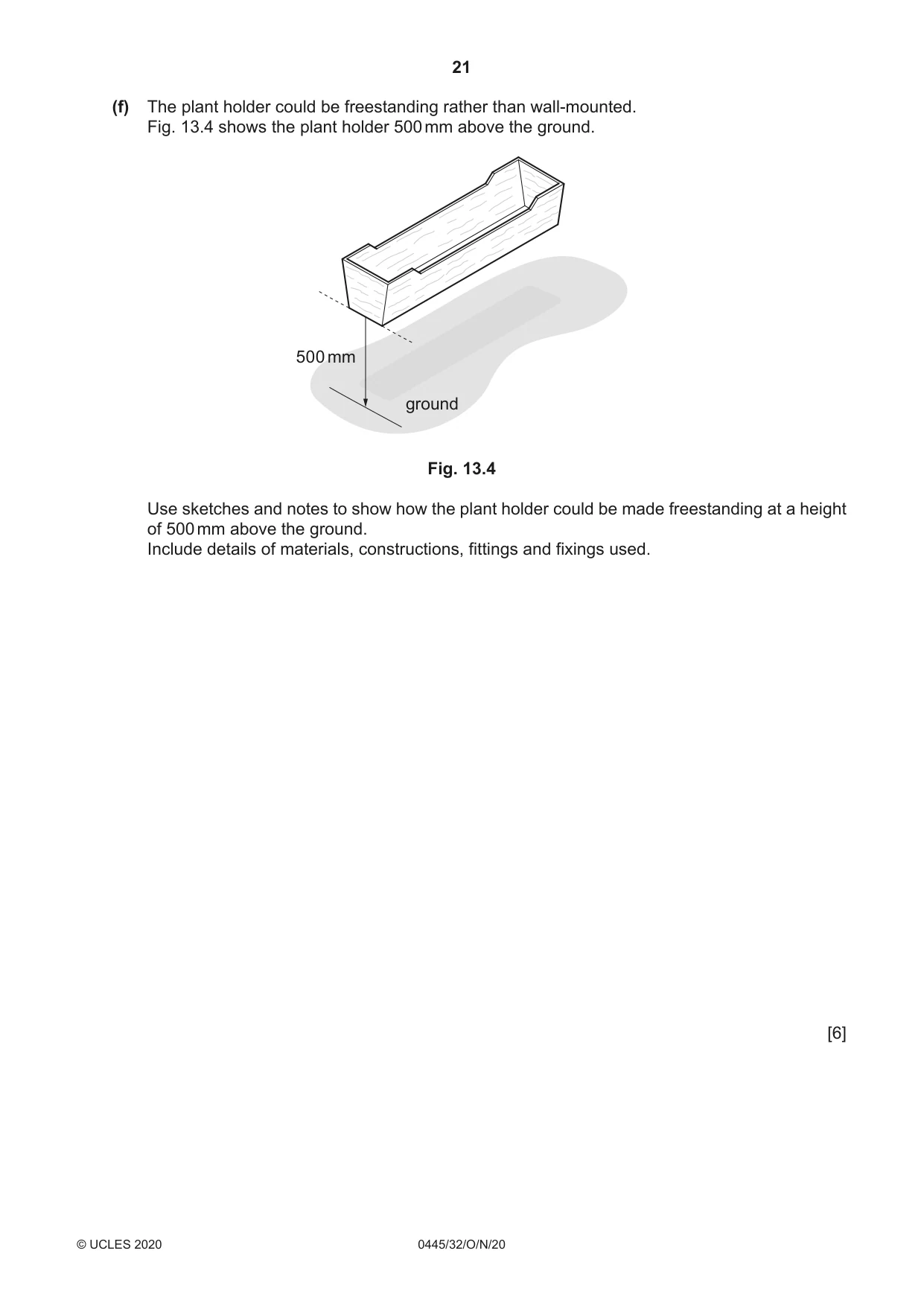


Mark scheme10 pages
Answers below. Sit the paper first if you are practising.
Questions as text
Q1 · Parts of a fastening device
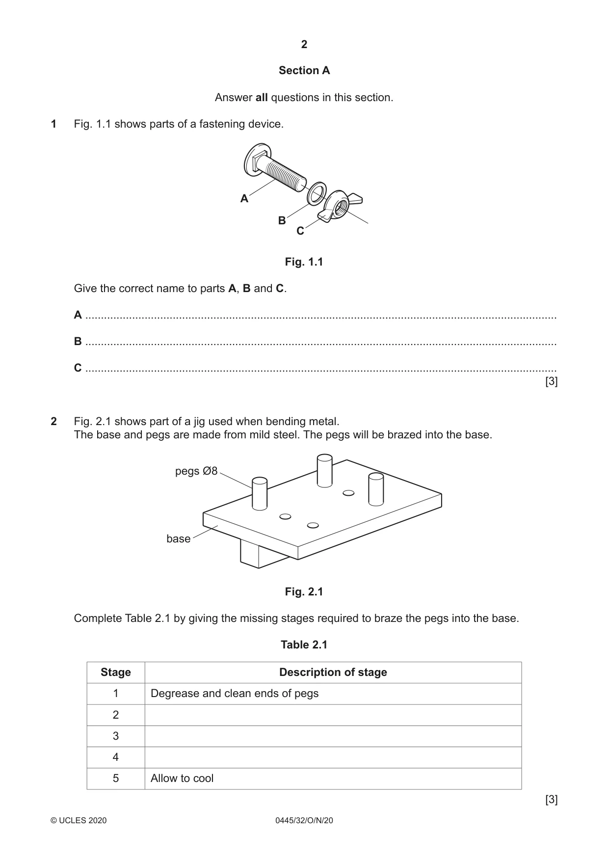
1 Fig. 1.1 shows parts of a fastening device. A B C Fig. 1.1 Give the correct name to parts A, B and C. A ....................................................................................................................................................... B ....................................................................................................................................................... C ....................................................................................................................................................... [3]
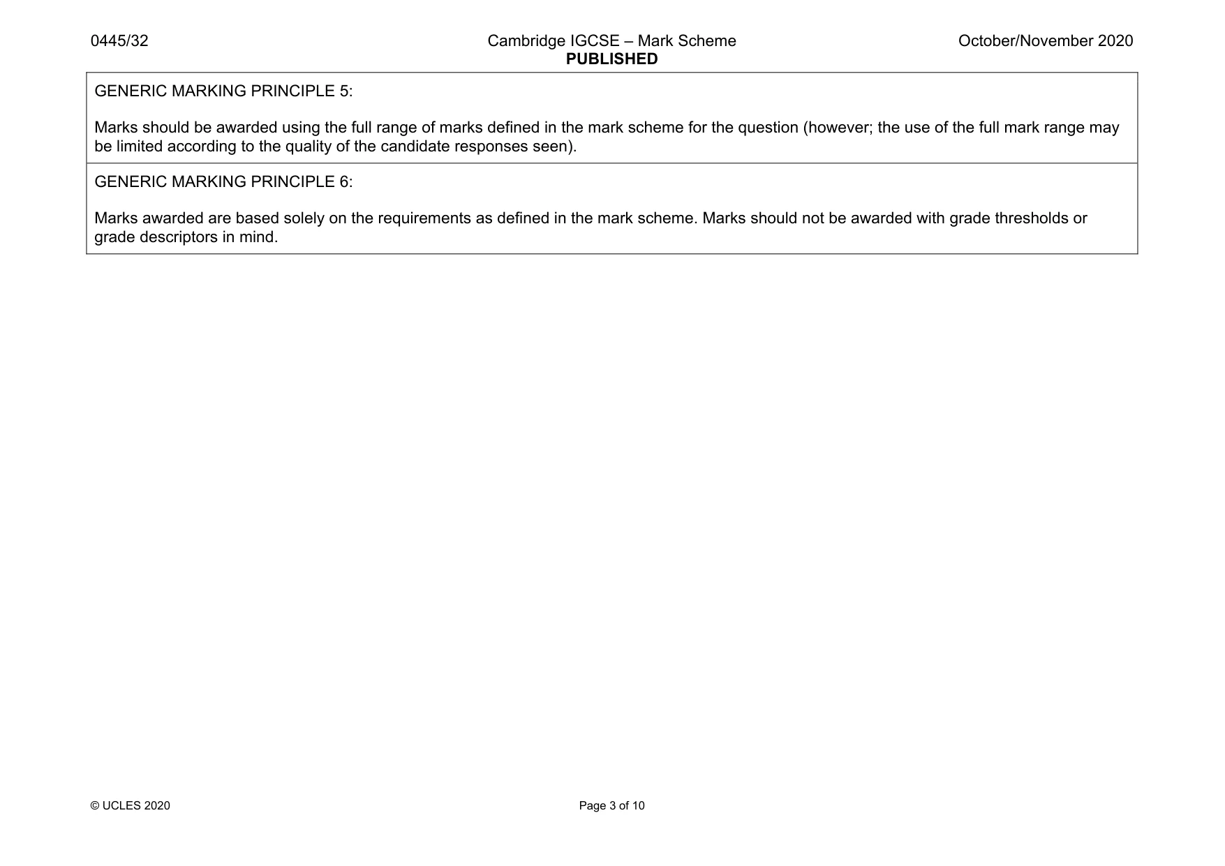
Mark scheme: 1 A bolt, screw [thread] 1 B washer 1 C wing nut, 1 3
Q2 · Part of a jig used when bending metal
2 Fig. 2.1 shows part of a jig used when bending metal. The base and pegs are made from mild steel. The pegs will be brazed into the base. pegs Ø8 base Fig. 2.1 Complete Table 2.1 by giving the missing stages required to braze the pegs into the base. Table 2.1 Stage Description of stage 1 Degrease and clean ends of pegs 2 3 4 5 Allow to cool [3]
Mark scheme: 2 3 stages include: apply flux, insert pegs into holes, position on hearth [firebricks], heat to appropriate temperature, apply brazing rod, make sure brazing rod ‘runs’ into joint, degrease holes 3 × 1
Q3 · Views of a mortise and tenon joint
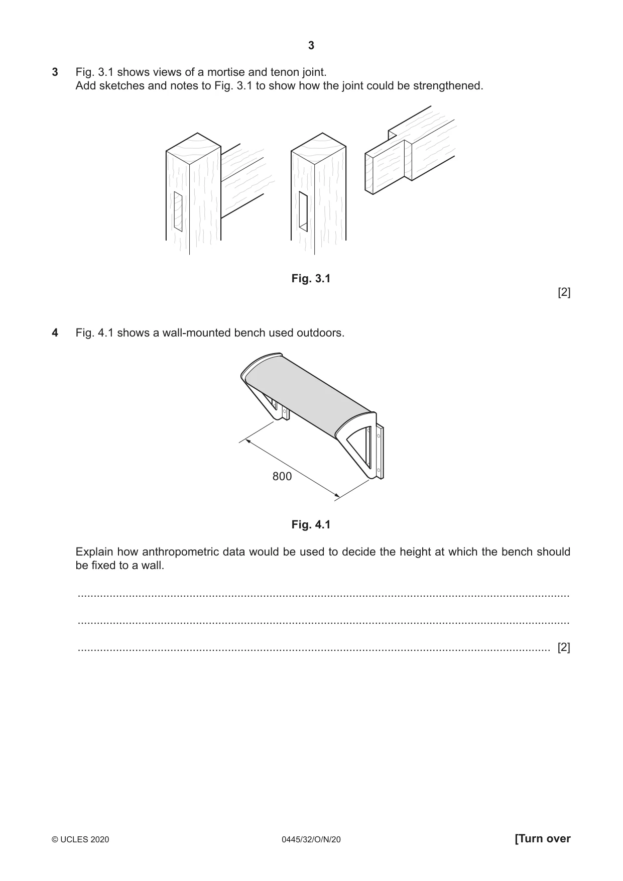
3 Fig. 3.1 shows views of a mortise and tenon joint. Add sketches and notes to Fig. 3.1 to show how the joint could be strengthened. Fig. 3.1 [2]
Mark scheme: 3 Methods: use of a wedge, dowel, nails, screws, bolts 1 nail/screw/bolt = 1mark 2 nails/screws/bolts = 2 marks 1 or 2 dowels = 2 marks
Q4 · A wall-mounted bench used outdoors
4 Fig. 4.1 shows a wall-mounted bench used outdoors. 800 Fig. 4.1 Explain how anthropometric data would be used to decide the height at which the bench should be fixed to a wall. .......................................................................................................................................................... .......................................................................................................................................................... .................................................................................................................................................... [2]
Mark scheme: 4 Basic understanding of the term ‘anthropometrics’ 1 Height dependent on distance from part of the leg behind the knee to the ground [popliteal height]. 1 2 Reference to human measurements
Q5 · Explain what is meant by the term ‘alloy’
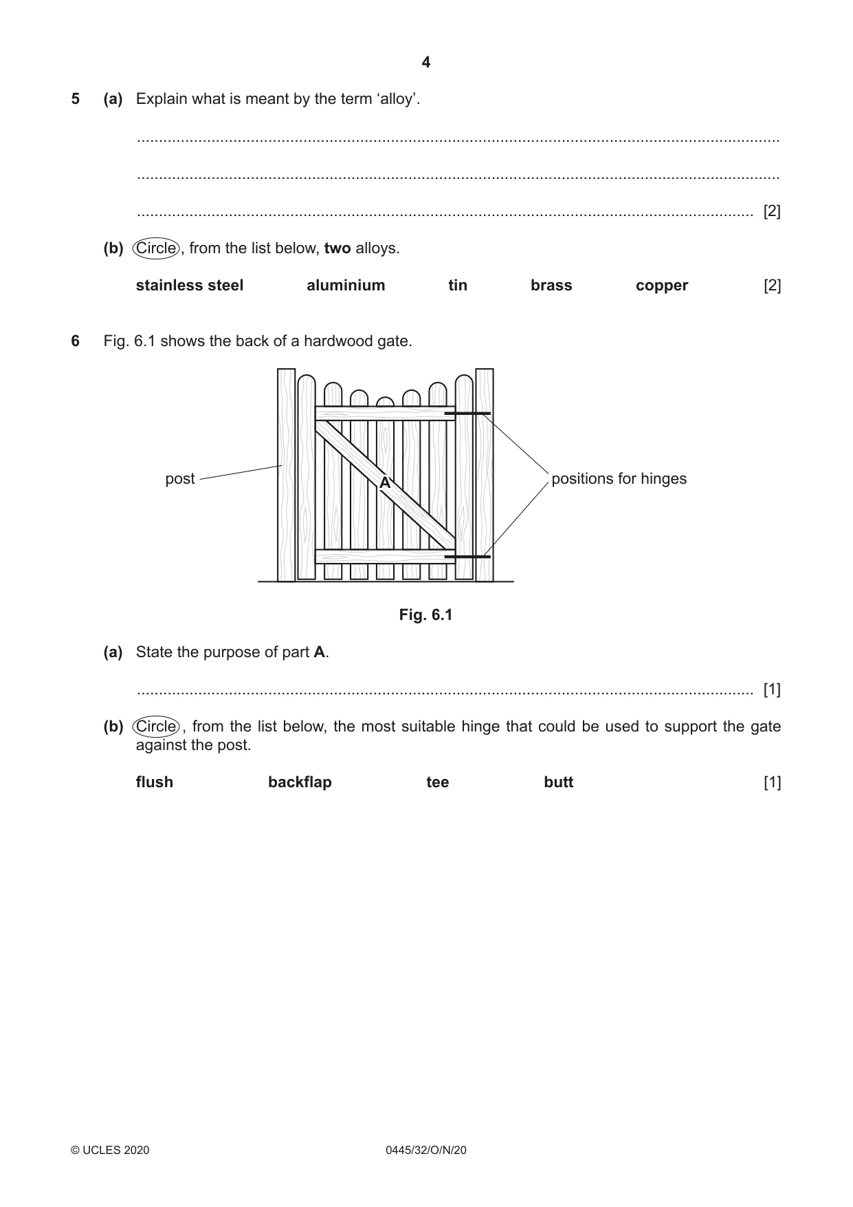
5 (a) Explain what is meant by the term ‘alloy’. ................................................................................................................................................... ................................................................................................................................................... ............................................................................................................................................. [2] (b) Circle , from the list below, two alloys. stainless steel aluminium tin brass copper [2]
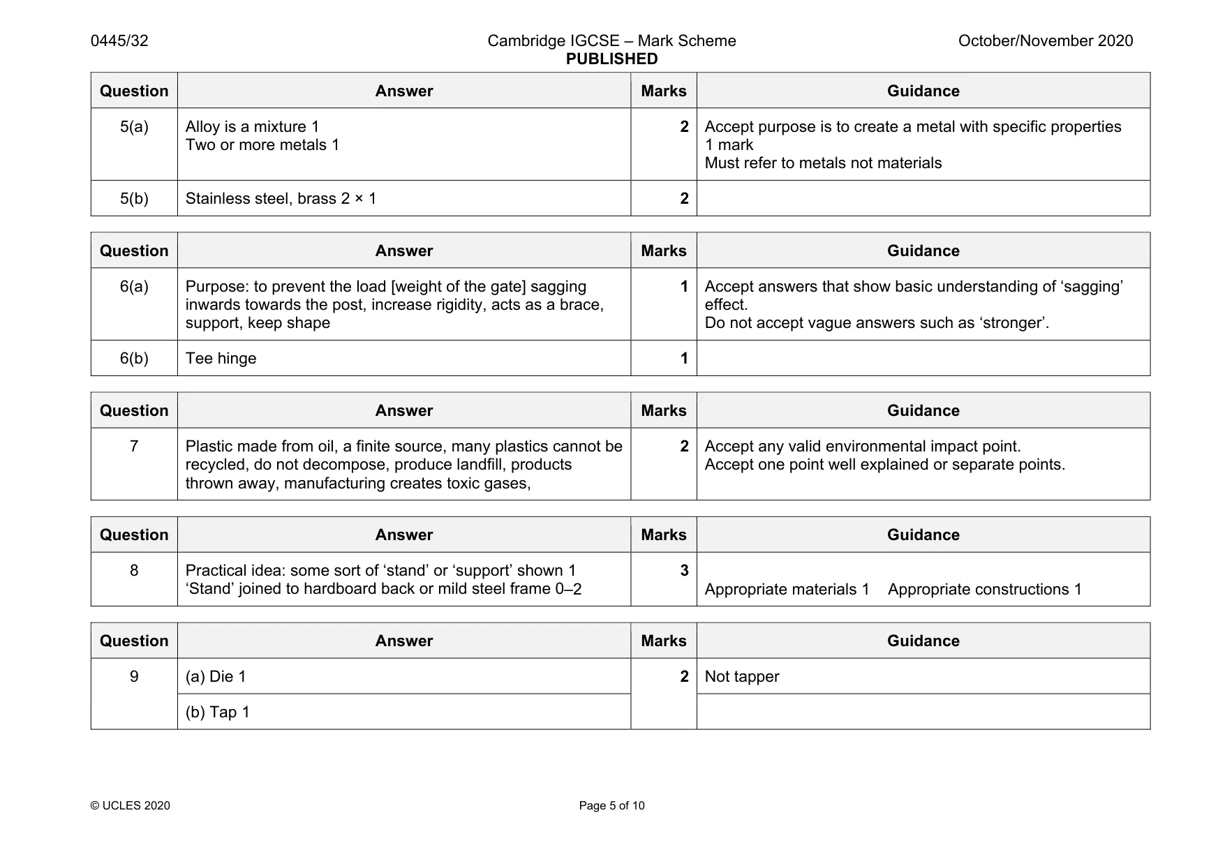
Mark scheme: 5(a) Alloy is a mixture 1 Two or more metals 1 2 Accept purpose is to create a metal with specific properties 1 mark Must refer to metals not materials 5(b) Stainless steel, brass 2 × 1 2
Q6 · The back of a hardwood gate
6 Fig. 6.1 shows the back of a hardwood gate. post positions for hinges A Fig. 6.1 (a) State the purpose of part A. ............................................................................................................................................. [1] (b) Circle , from the list below, the most suitable hinge that could be used to support the gate against the post. flush backflap tee butt [1]
Mark scheme: 6(a) Purpose: to prevent the load [weight of the gate] sagging inwards towards the post, increase rigidity, acts as a brace, support, keep shape 1 Accept answers that show basic understanding of ‘sagging’ effect. Do not accept vague answers such as ‘stronger’. 6(b) Tee hinge 1
Q7 · A notelet holder made from plastic
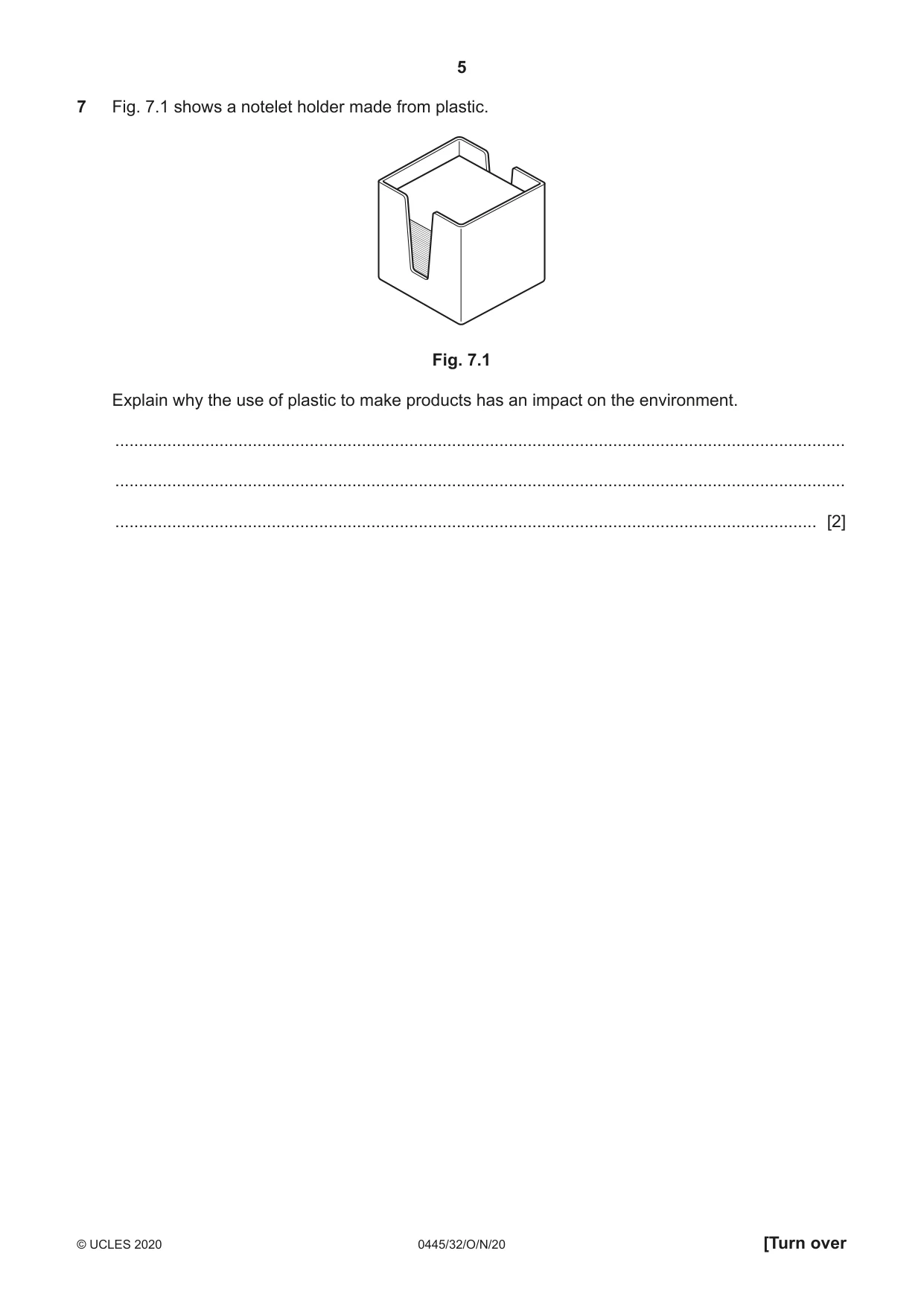
7 Fig. 7.1 shows a notelet holder made from plastic. Fig. 7.1 Explain why the use of plastic to make products has an impact on the environment. .......................................................................................................................................................... .......................................................................................................................................................... .................................................................................................................................................... [2]
Mark scheme: 7 Plastic made from oil, a finite source, many plastics cannot be recycled, do not decompose, produce landfill, products thrown away, manufacturing creates toxic gases, 2 Accept any valid environmental impact point. Accept one point well explained or separate points.
Q8 · Views of an incomplete design for a photograph frame
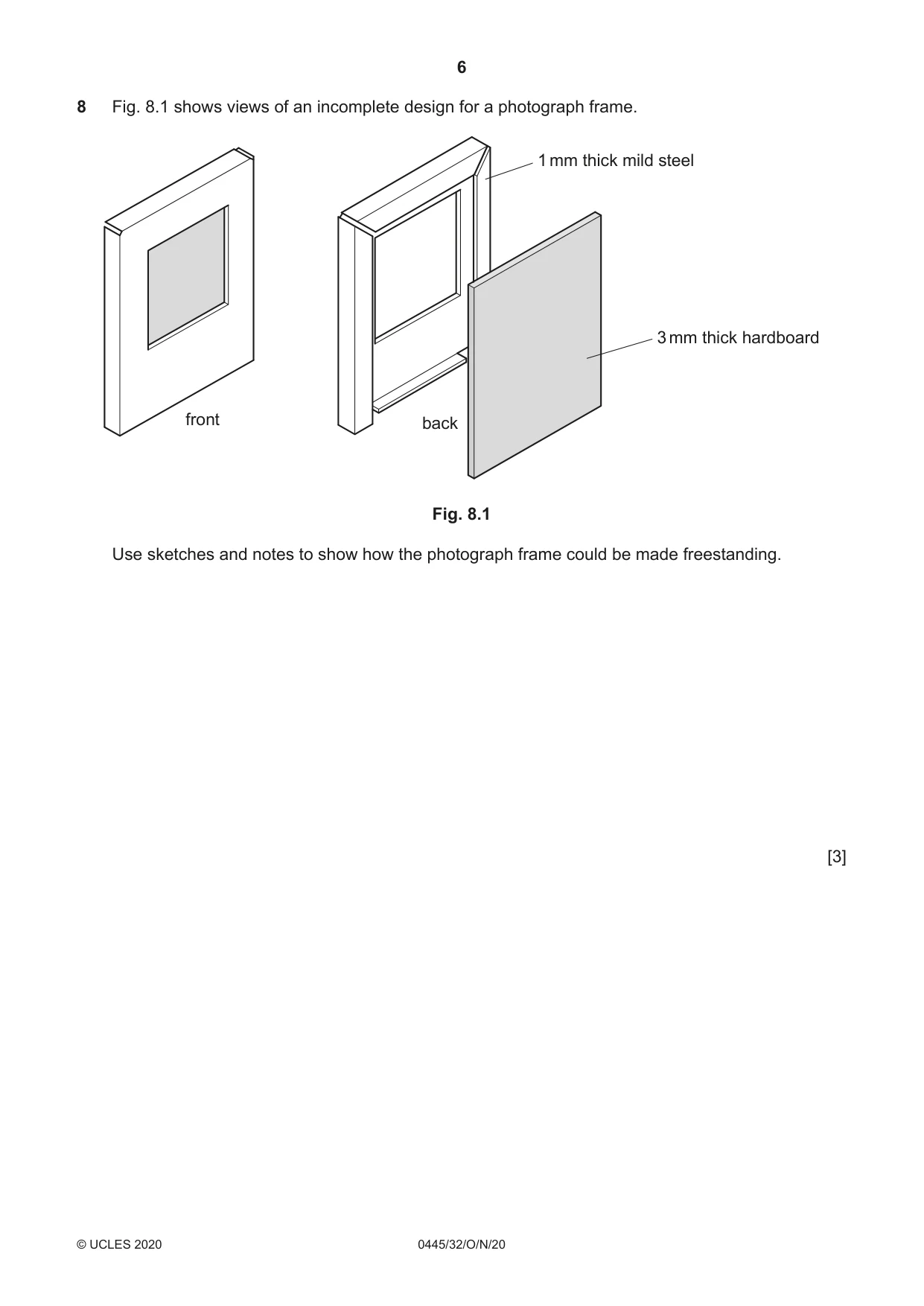
8 Fig. 8.1 shows views of an incomplete design for a photograph frame. 1 mm thick mild steel 3 mm thick hardboard front back Fig. 8.1 Use sketches and notes to show how the photograph frame could be made freestanding. [3]
Mark scheme: 8 Practical idea: some sort of ‘stand’ or ‘support’ shown 1 ‘Stand’ joined to hardboard back or mild steel frame 0–2 3 Appropriate materials 1 Appropriate constructions 1
Q9 · A mild steel rod that will be joined to a mild steel base by means of a screw thread
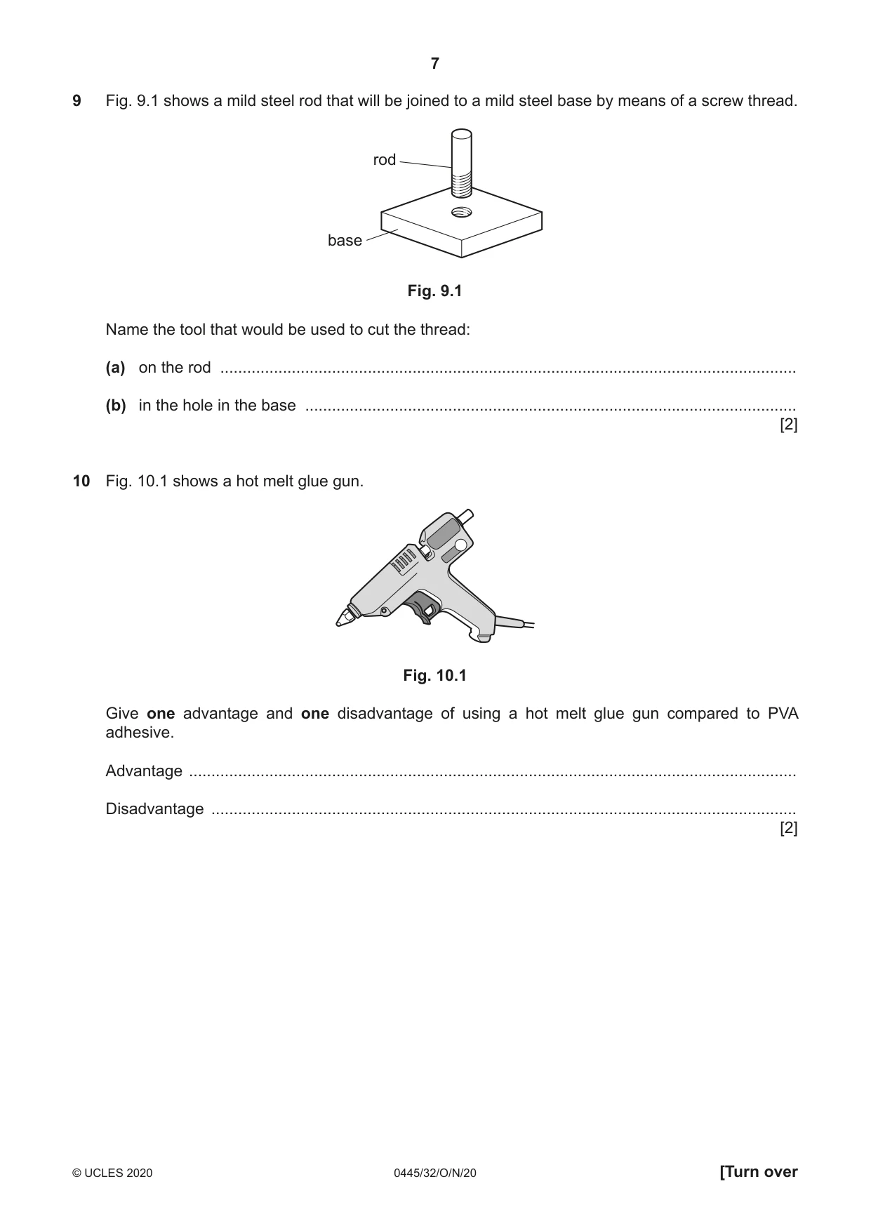
9 Fig. 9.1 shows a mild steel rod that will be joined to a mild steel base by means of a screw thread. rod base Fig. 9.1 Name the tool that would be used to cut the thread: (a) on the rod ................................................................................................................................. (b) in the hole in the base .............................................................................................................. [2]
Mark scheme: 9 (a) Die 1 2 Not tapper (b) Tap 1
Q10 · A hot melt glue gun
10 Fig. 10.1 shows a hot melt glue gun. Fig. 10.1 Give one advantage and one disadvantage of using a hot melt glue gun compared to PVA adhesive. Advantage ........................................................................................................................................ Disadvantage ................................................................................................................................... [2]
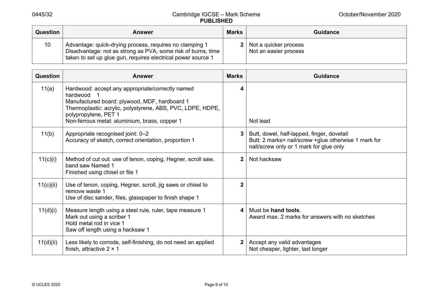
Mark scheme: 10 Advantage: quick-drying process, requires no clamping 1 Disadvantage: not as strong as PVA, some risk of burns, time taken to set up glue gun, requires electrical power source 1 2 Not a quicker process Not an easier process
Q11 · A balance that will be used by young children
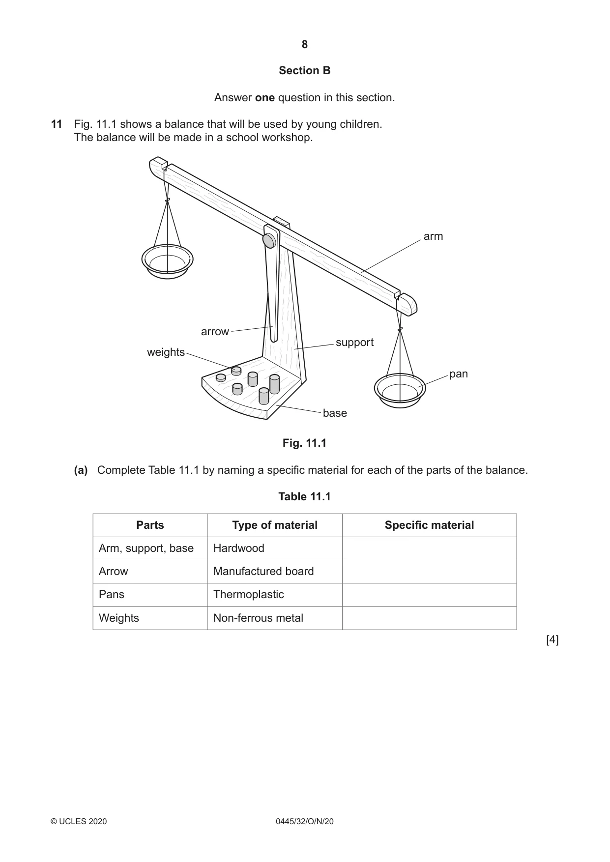
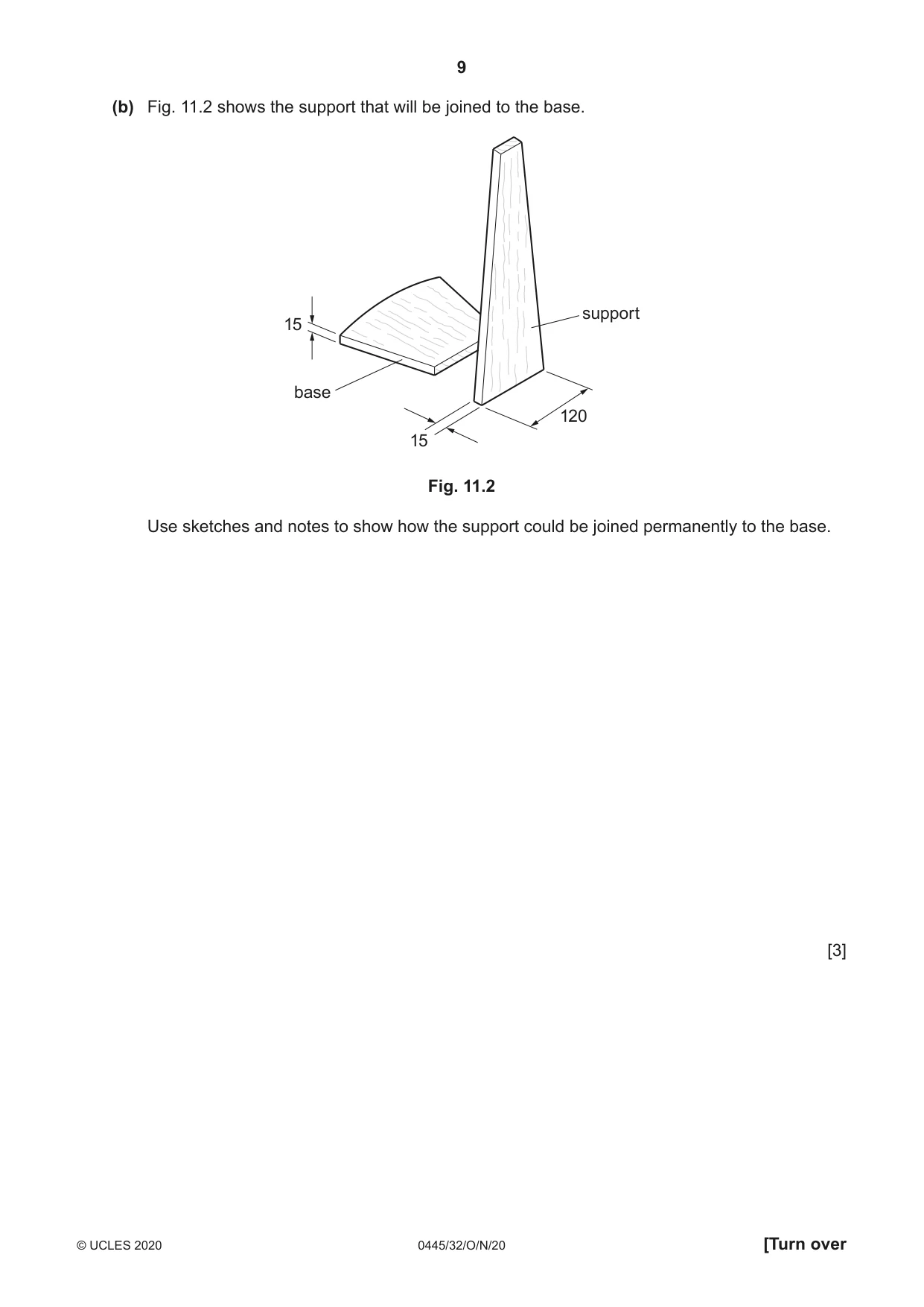
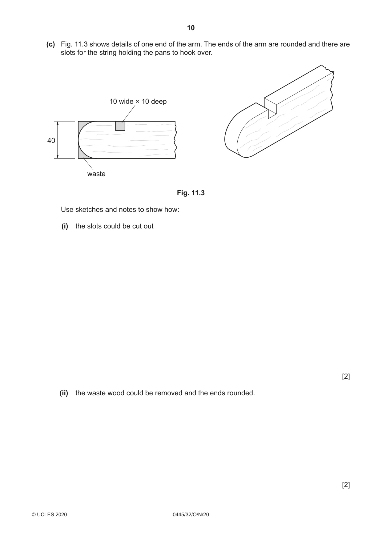
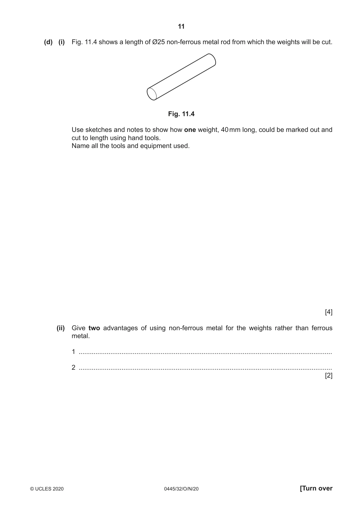
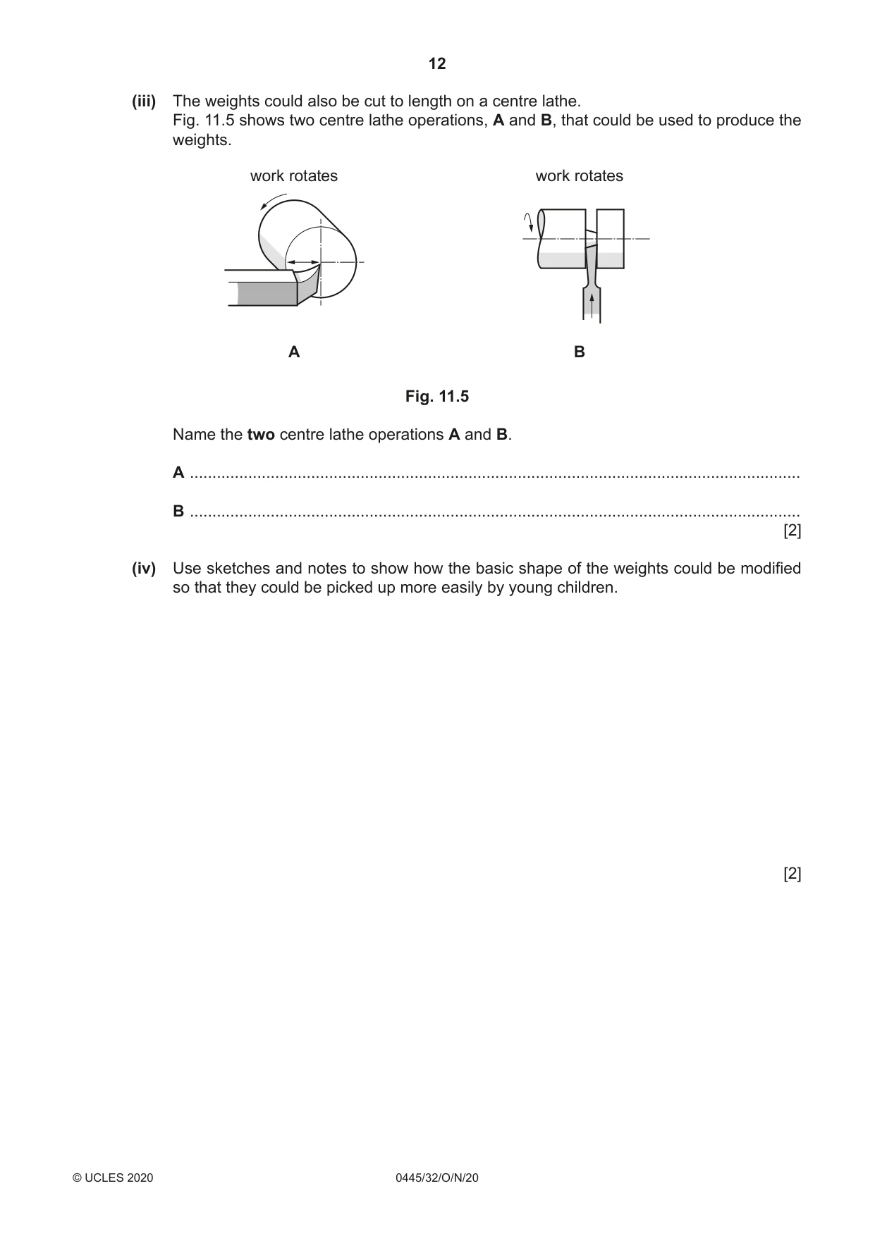
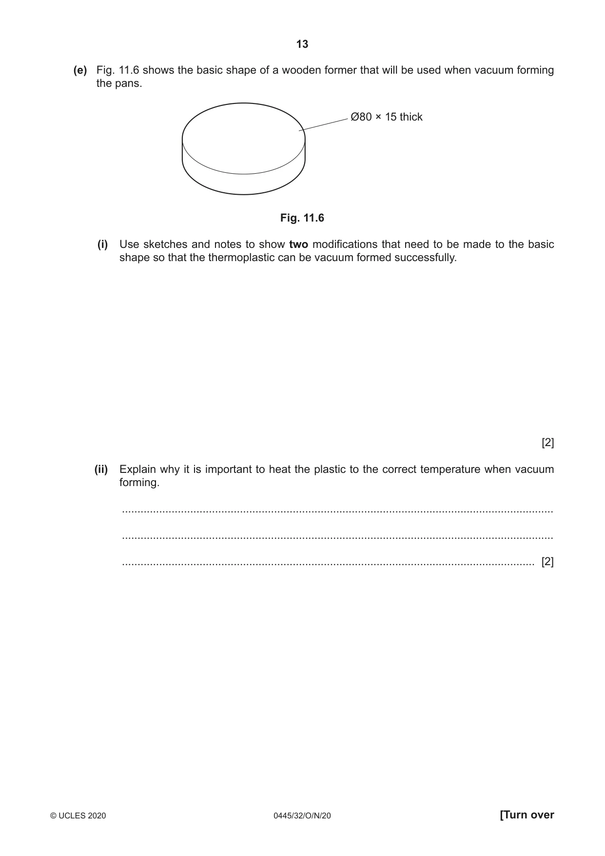
11 Fig. 11.1 shows a balance that will be used by young children. The balance will be made in a school workshop. arm arrow support weights pan base Fig. 11.1 (a) Complete Table 11.1 by naming a specific material for each of the parts of the balance. Table 11.1 Parts Type of material Specific material Arm, support, base Hardwood Arrow Manufactured board Pans Thermoplastic Weights Non-ferrous metal [4] (b) Fig. 11.2 shows the support that will be joined to the base. support 15 base 120 15 Fig. 11.2 Use sketches and notes to show how the support could be joined permanently to the base. [3] (c) Fig. 11.3 shows details of one end of the arm. The ends of the arm are rounded and there are slots for the string holding the pans to hook over. 10 wide × 10 deep 40 waste Fig. 11.3 Use sketches and notes to show how: (i) the slots could be cut out [2] (ii) the waste wood could be removed and the ends rounded. [2] (d) (i) Fig. 11.4 shows a length of Ø25 non-ferrous metal rod from which the weights will be cut. Fig. 11.4 Use sketches and notes to show how one weight, 40 mm long, could be marked out and cut to length using hand tools. Name all the tools and equipment used. [4] (ii) Give two advantages of using non-ferrous metal for the weights rather than ferrous metal. 1 ........................................................................................................................................ 2 ........................................................................................................................................ [2] (iii) The weights could also be cut to length on a centre lathe. Fig. 11.5 shows two centre lathe operations, A and B, that could be used to produce the weights. work rotates work rotates A B Fig. 11.5 Name the two centre lathe operations A and B. A ........................................................................................................................................ B ........................................................................................................................................ [2] (iv) Use sketches and notes to show how the basic shape of the weights could be modified so that they could be picked up more easily by young children. [2] (e) Fig. 11.6 shows the basic shape of a wooden former that will be used when vacuum forming the pans. Ø80 × 15 thick Fig. 11.6 (i) Use sketches and notes to show two modifications that need to be made to the basic shape so that the thermoplastic can be vacuum formed successfully. [2] (ii) Explain why it is important to heat the plastic to the correct temperature when vacuum forming. ........................................................................................................................................... ........................................................................................................................................... ..................................................................................................................................... [2]
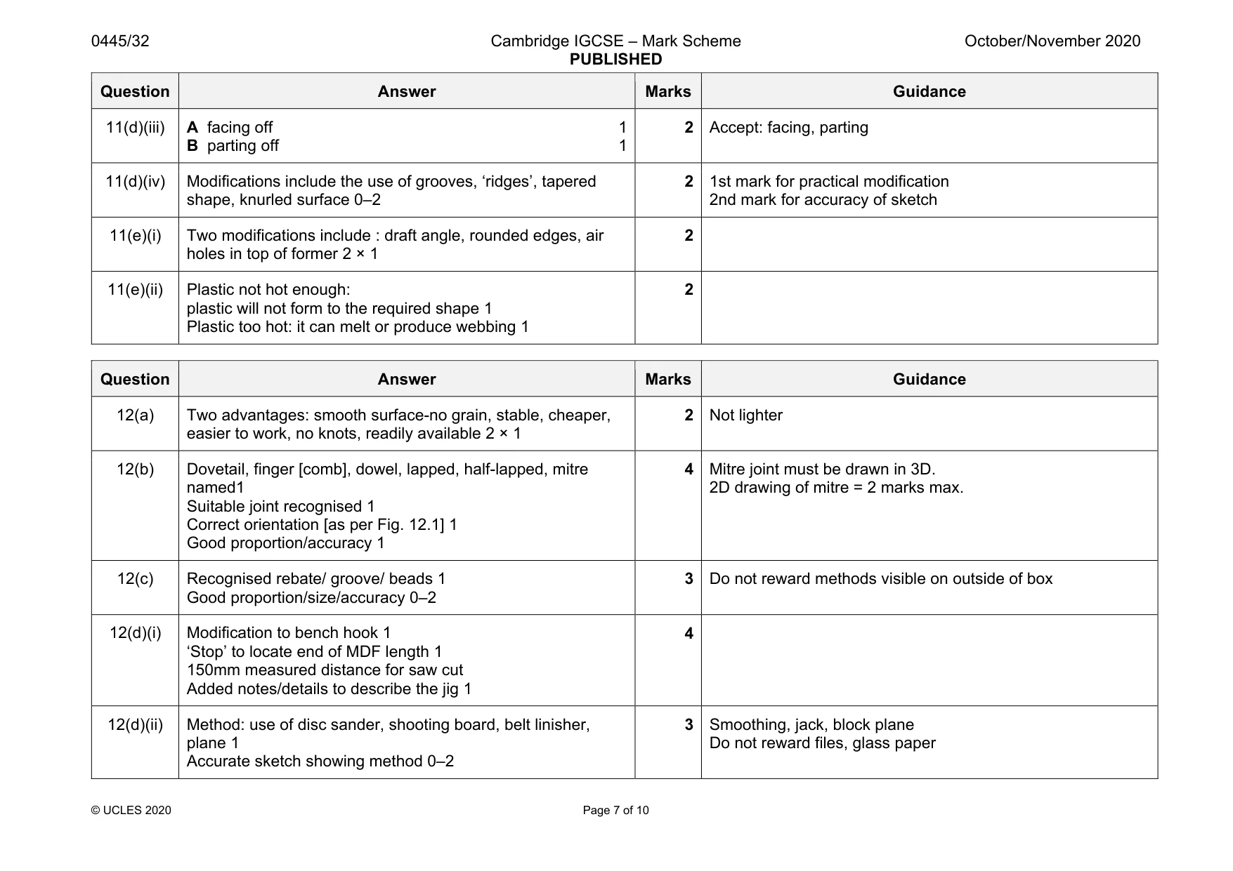
Mark scheme: 11(a) Hardwood: accept any appropriate/correctly named hardwood 1 Manufactured board: plywood, MDF, hardboard 1 Thermoplastic: acrylic, polystyrene, ABS, PVC, LDPE, HDPE, polypropylene, PET 1 Non-ferrous metal: aluminium, brass, copper 1 Not lead 11(b) Appropriate recognised joint: 0–2 Accuracy of sketch, correct orientation, proportion 1 3 Butt, dowel, half-lapped, finger, dovetail Butt: 2 marks= nail/screw +glue otherwise 1 mark for nail/screw only or 1 mark for glue only 11(c)(i) Method of cut out: use of tenon, coping, Hegner, scroll saw, band saw Named 1 Finished using chisel or file 1 2 Not hacksaw 11(c)(ii) Use of tenon, coping, Hegner, scroll, jig saws or chisel to remove waste 1 Use of disc sander, files, glasspaper to finish shape 1 2 11(d)(i) Measure length using a steel rule, ruler, tape measure 1 Mark out using a scriber 1 Hold metal rod in vice 1 Saw off length using a hacksaw 1 4 Must be hand tools. Award max. 2 marks for answers with no sketches 11(d)(ii) Less likely to corrode, self-finishing, do not need an applied finish, attractive 2 × 1 2 Accept any valid advantages Not cheaper, lighter, last longer Question Answer Marks Guidance 11(d)(iii) A facing off 1 B parting off 1 2 Accept: facing, parting 11(d)(iv) Modifications include the use of grooves, ‘ridges’, tapered shape, knurled surface 0–2 2 1st mark for practical modification 2nd mark for accuracy of sketch 11(e)(i) Two modifications include : draft angle, rounded edges, air holes in top of former 2 × 1 2 11(e)(ii) Plastic not hot enough: plastic will not form to the required shape 1 Plastic too hot: it can melt or produce webbing 1 2
Q12 · A box of giant dominoes used by young children
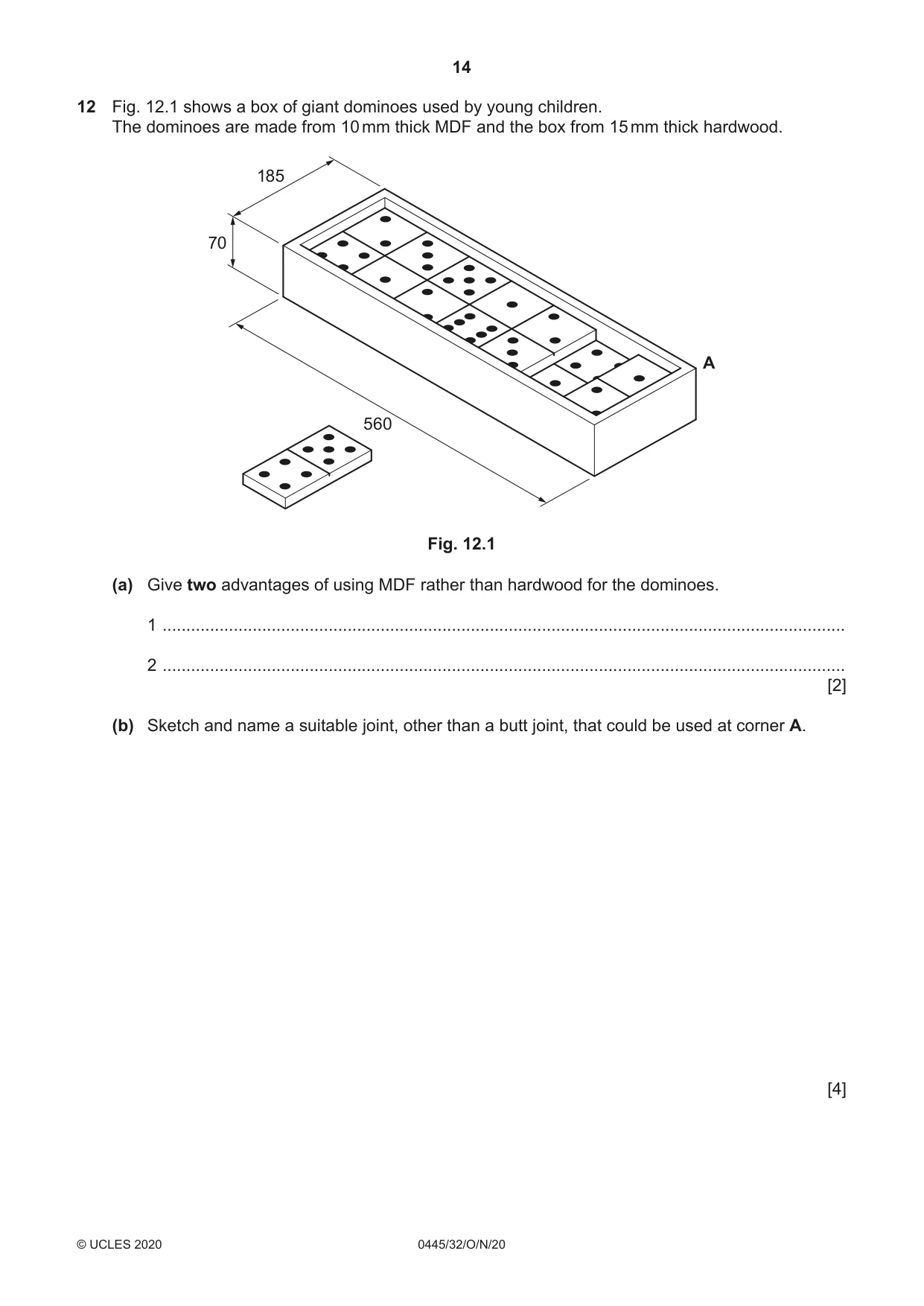
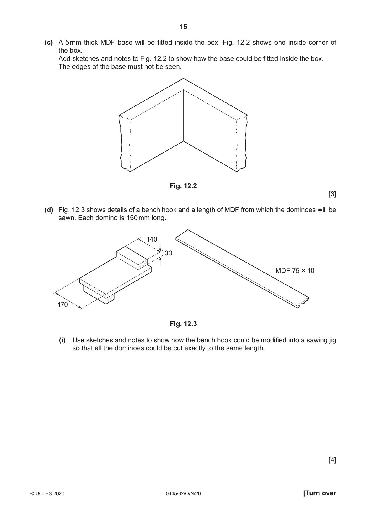
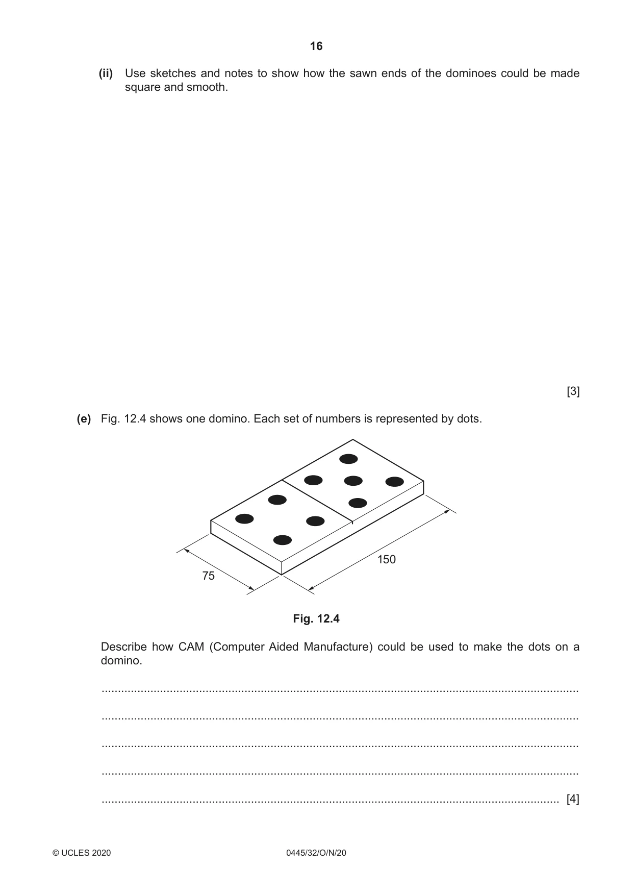
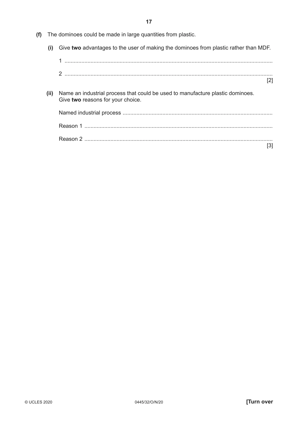
12 Fig. 12.1 shows a box of giant dominoes used by young children. The dominoes are made from 10 mm thick MDF and the box from 15 mm thick hardwood. 185 70 A 560 Fig. 12.1 (a) Give two advantages of using MDF rather than hardwood for the dominoes. 1 ................................................................................................................................................ 2 ................................................................................................................................................ [2] (b) Sketch and name a suitable joint, other than a butt joint, that could be used at corner A. [4] (c) A 5 mm thick MDF base will be fitted inside the box. Fig. 12.2 shows one inside corner of the box. Add sketches and notes to Fig. 12.2 to show how the base could be fitted inside the box. The edges of the base must not be seen. Fig. 12.2 [3] (d) Fig. 12.3 shows details of a bench hook and a length of MDF from which the dominoes will be sawn. Each domino is 150 mm long. 140 30 MDF 75 × 10 170 Fig. 12.3 (i) Use sketches and notes to show how the bench hook could be modified into a sawing jig so that all the dominoes could be cut exactly to the same length. [4] (ii) Use sketches and notes to show how the sawn ends of the dominoes could be made square and smooth. [3] (e) Fig. 12.4 shows one domino. Each set of numbers is represented by dots. 150 75 Fig. 12.4 Describe how CAM (Computer Aided Manufacture) could be used to make the dots on a domino. ................................................................................................................................................... ................................................................................................................................................... ................................................................................................................................................... ................................................................................................................................................... ............................................................................................................................................. [4] (f) The dominoes could be made in large quantities from plastic. (i) Give two advantages to the user of making the dominoes from plastic rather than MDF. 1 ........................................................................................................................................ 2 ........................................................................................................................................ [2] (ii) Name an industrial process that could be used to manufacture plastic dominoes. Give two reasons for your choice. Named industrial process .................................................................................................. Reason 1 ........................................................................................................................... Reason 2 ........................................................................................................................... [3]
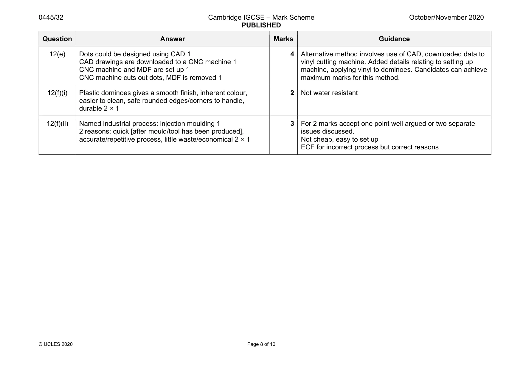
Mark scheme: 12(a) Two advantages: smooth surface-no grain, stable, cheaper, easier to work, no knots, readily available 2 × 1 2 Not lighter 12(b) Dovetail, finger [comb], dowel, lapped, half-lapped, mitre named1 Suitable joint recognised 1 Correct orientation [as per Fig. 12.1] 1 Good proportion/accuracy 1 4 Mitre joint must be drawn in 3D. 2D drawing of mitre = 2 marks max. 12(c) Recognised rebate/ groove/ beads 1 Good proportion/size/accuracy 0–2 3 Do not reward methods visible on outside of box 12(d)(i) Modification to bench hook 1 ‘Stop’ to locate end of MDF length 1 150mm measured distance for saw cut Added notes/details to describe the jig 1 4 12(d)(ii) Method: use of disc sander, shooting board, belt linisher, plane 1 Accurate sketch showing method 0–2 3 Smoothing, jack, block plane Do not reward files, glass paper Question Answer Marks Guidance 12(e) Dots could be designed using CAD 1 CAD drawings are downloaded to a CNC machine 1 CNC machine and MDF are set up 1 CNC machine cuts out dots, MDF is removed 1 4 Alternative method involves use of CAD, downloaded data to vinyl cutting machine. Added details relating to setting up machine, applying vinyl to dominoes. Candidates can achieve maximum marks for this method. 12(f)(i) Plastic dominoes gives a smooth finish, inherent colour, easier to clean, safe rounded edges/corners to handle, durable 2 × 1 2 Not water resistant 12(f)(ii) Named industrial process: injection moulding 1 2 reasons: quick [after mould/tool has been produced], accurate/repetitive process, little waste/economical 2 × 1 3 For 2 marks accept one point well argued or two separate issues discussed. Not cheap, easy to set up ECF for incorrect process but correct reasons
Q13 · A plant holder and the brackets that will support it on a wall
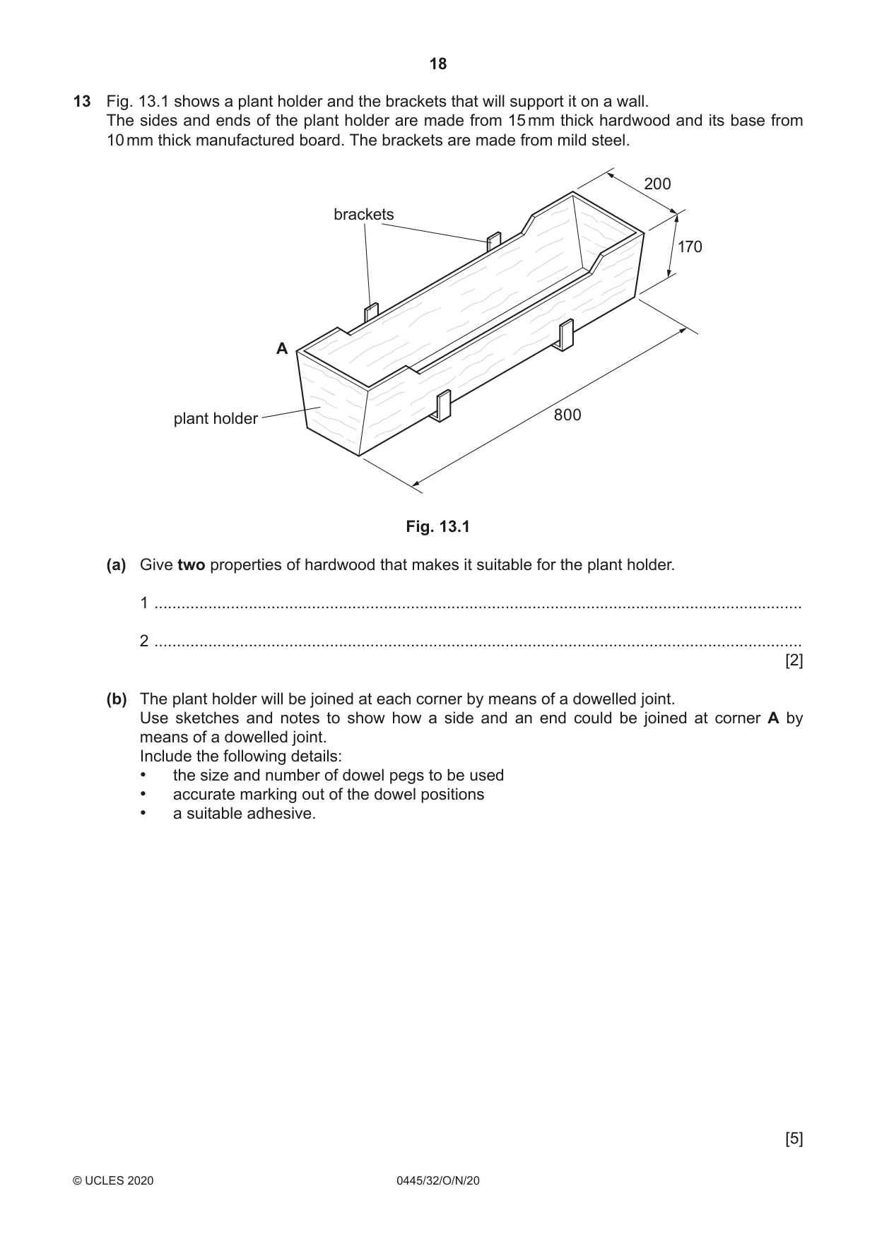
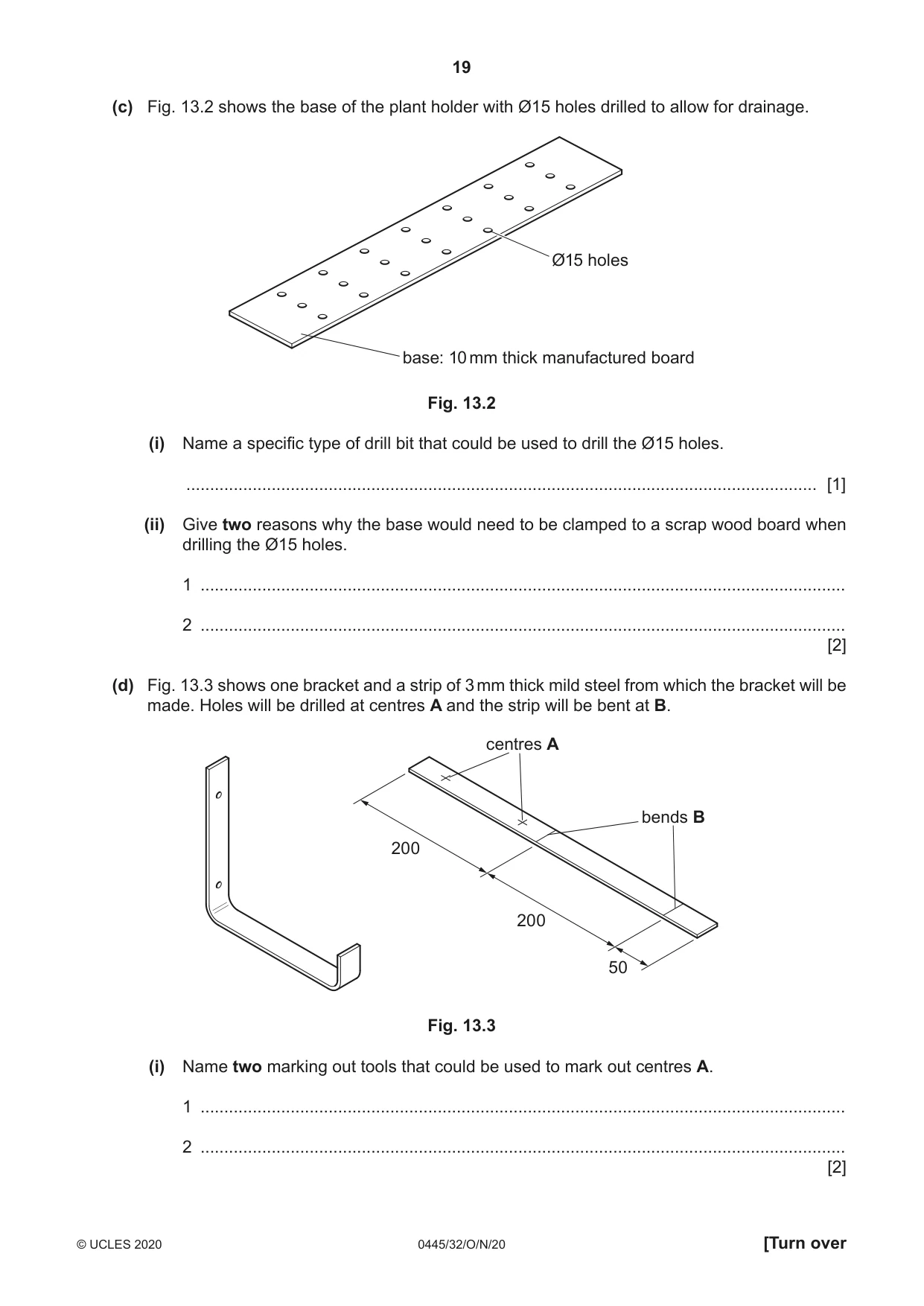
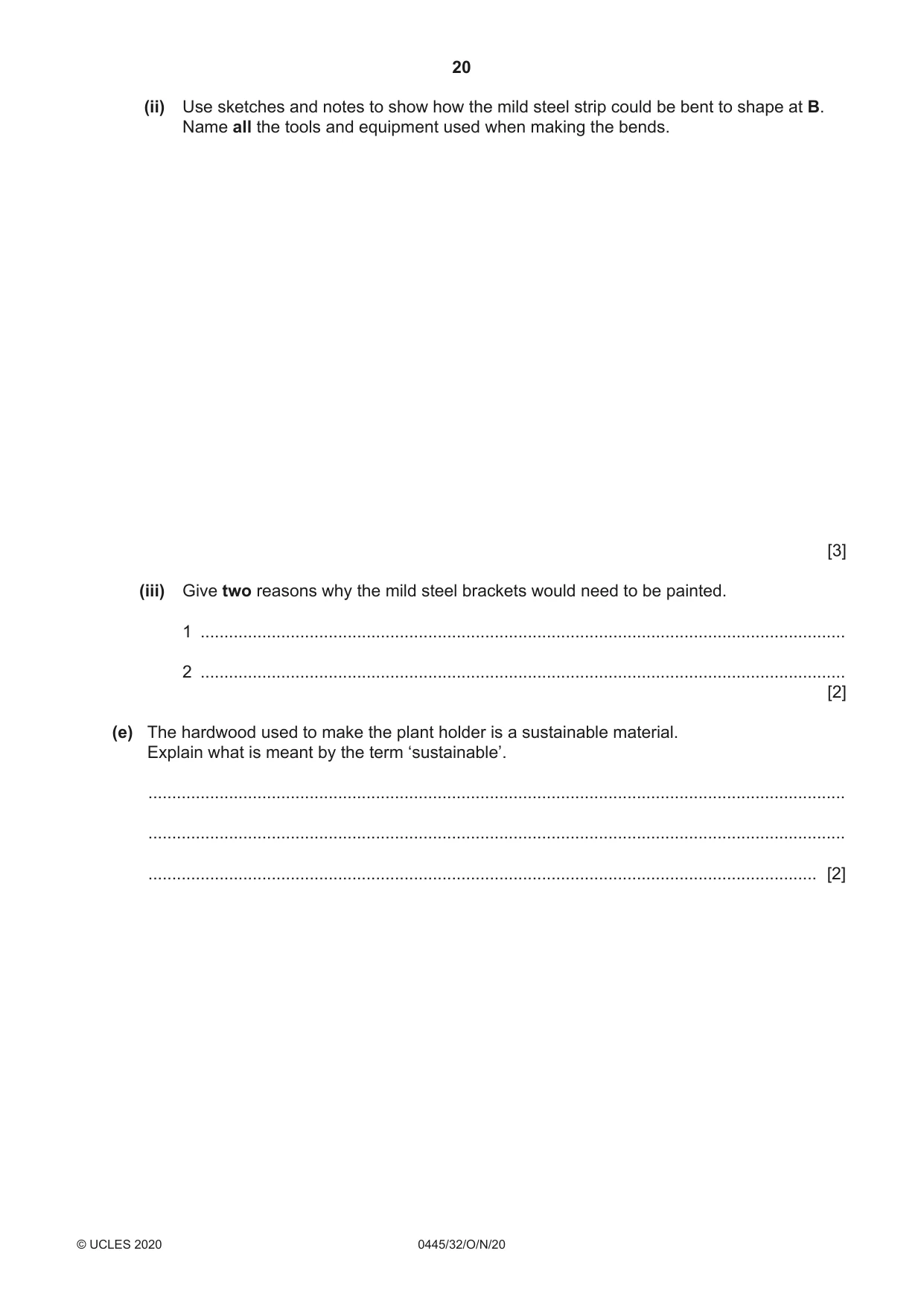
13 Fig. 13.1 shows a plant holder and the brackets that will support it on a wall. The sides and ends of the plant holder are made from 15 mm thick hardwood and its base from 10 mm thick manufactured board. The brackets are made from mild steel. 200 brackets 170 A plant holder 800 Fig. 13.1 (a) Give two properties of hardwood that makes it suitable for the plant holder. 1 ................................................................................................................................................ 2 ................................................................................................................................................ [2] (b) The plant holder will be joined at each corner by means of a dowelled joint. Use sketches and notes to show how a side and an end could be joined at corner A by means of a dowelled joint. Include the following details: • the size and number of dowel pegs to be used • accurate marking out of the dowel positions • a suitable adhesive. [5] (c) Fig. 13.2 shows the base of the plant holder with Ø15 holes drilled to allow for drainage. Ø15 holes base: 10 mm thick manufactured board Fig. 13.2 (i) Name a specific type of drill bit that could be used to drill the Ø15 holes. ..................................................................................................................................... [1] (ii) Give two reasons why the base would need to be clamped to a scrap wood board when drilling the Ø15 holes. 1 ........................................................................................................................................ 2 ........................................................................................................................................ [2] (d) Fig. 13.3 shows one bracket and a strip of 3 mm thick mild steel from which the bracket will be made. Holes will be drilled at centres A and the strip will be bent at B. centres A bends B 200 200 50 Fig. 13.3 (i) Name two marking out tools that could be used to mark out centres A. 1 ........................................................................................................................................ 2 ........................................................................................................................................ [2] (ii) Use sketches and notes to show how the mild steel strip could be bent to shape at B. Name all the tools and equipment used when making the bends. [3] (iii) Give two reasons why the mild steel brackets would need to be painted. 1 ........................................................................................................................................ 2 ........................................................................................................................................ [2] (e) The hardwood used to make the plant holder is a sustainable material. Explain what is meant by the term ‘sustainable’. ................................................................................................................................................... ................................................................................................................................................... ............................................................................................................................................. [2]
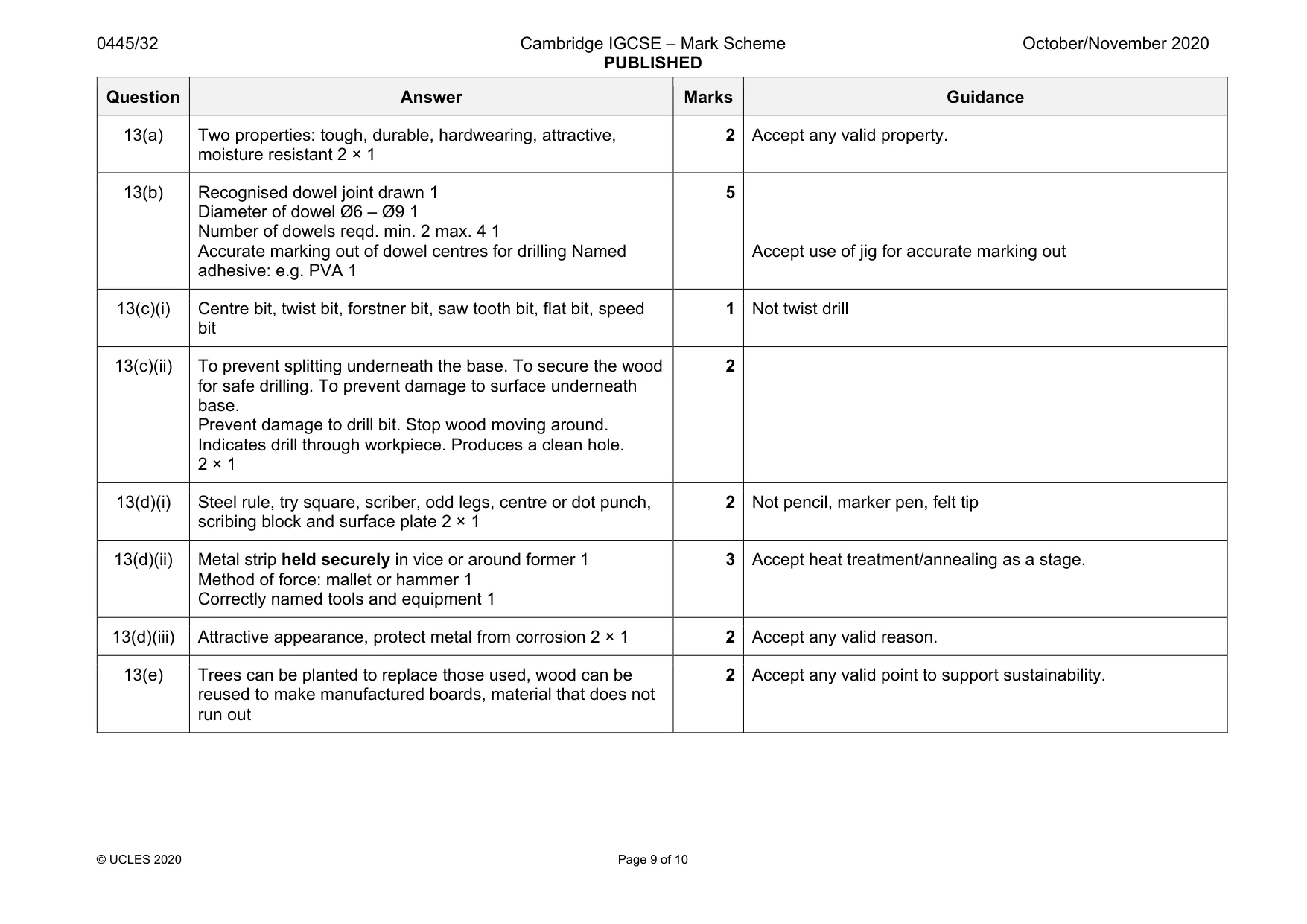
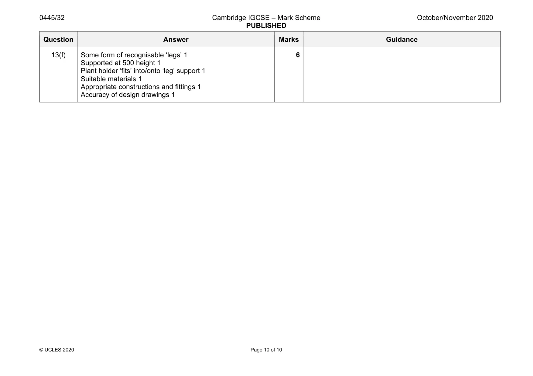
Mark scheme: 13(a) Two properties: tough, durable, hardwearing, attractive, moisture resistant 2 × 1 2 Accept any valid property. 13(b) Recognised dowel joint drawn 1 Diameter of dowel Ø6 – Ø9 1 Number of dowels reqd. min. 2 max. 4 1 Accurate marking out of dowel centres for drilling Named adhesive: e.g. PVA 1 5 Accept use of jig for accurate marking out 13(c)(i) Centre bit, twist bit, forstner bit, saw tooth bit, flat bit, speed bit 1 Not twist drill 13(c)(ii) To prevent splitting underneath the base. To secure the wood for safe drilling. To prevent damage to surface underneath base. Prevent damage to drill bit. Stop wood moving around. Indicates drill through workpiece. Produces a clean hole. 2 × 1 2 13(d)(i) Steel rule, try square, scriber, odd legs, centre or dot punch, scribing block and surface plate 2 × 1 2 Not pencil, marker pen, felt tip 13(d)(ii) Metal strip held securely in vice or around former 1 Method of force: mallet or hammer 1 Correctly named tools and equipment 1 3 Accept heat treatment/annealing as a stage. 13(d)(iii) Attractive appearance, protect metal from corrosion 2 × 1 2 Accept any valid reason. 13(e) Trees can be planted to replace those used, wood can be reused to make manufactured boards, material that does not run out 2 Accept any valid point to support sustainability. Question Answer Marks Guidance 13(f) Some form of recognisable ‘legs’ 1 Supported at 500 height 1 Plant holder ‘fits’ into/onto ‘leg’ support 1 Suitable materials 1 Appropriate constructions and fittings 1 Accuracy of design drawings 1 6
What was in this paper
The subtopics covered by these 13 questions, and how many questions each got. Open one in a new tab to see every Cambridge question on it.
What you needed in this session
Cambridge’s own grade thresholds for 2020 Oct/Nov, Paper 3 · Variant 2. A higher threshold means an easier paper — the bar moves with how the cohort did.