Cambridge IGCSE Design and Technology 0445 — 2020 Oct/Nov Paper 3 · Variant 3
0445/33/O/N/20 · 13 questions · 50 marks · ≈56 min
The question paper and its mark scheme, free to read here and free to download. This is Cambridge’s own paper, exactly as it was sat.
Question paper20 pages
Mark scheme8 pages
Answers below. Sit the paper first if you are practising.
Questions as text
Q1 · Two standard timber sections, A and B
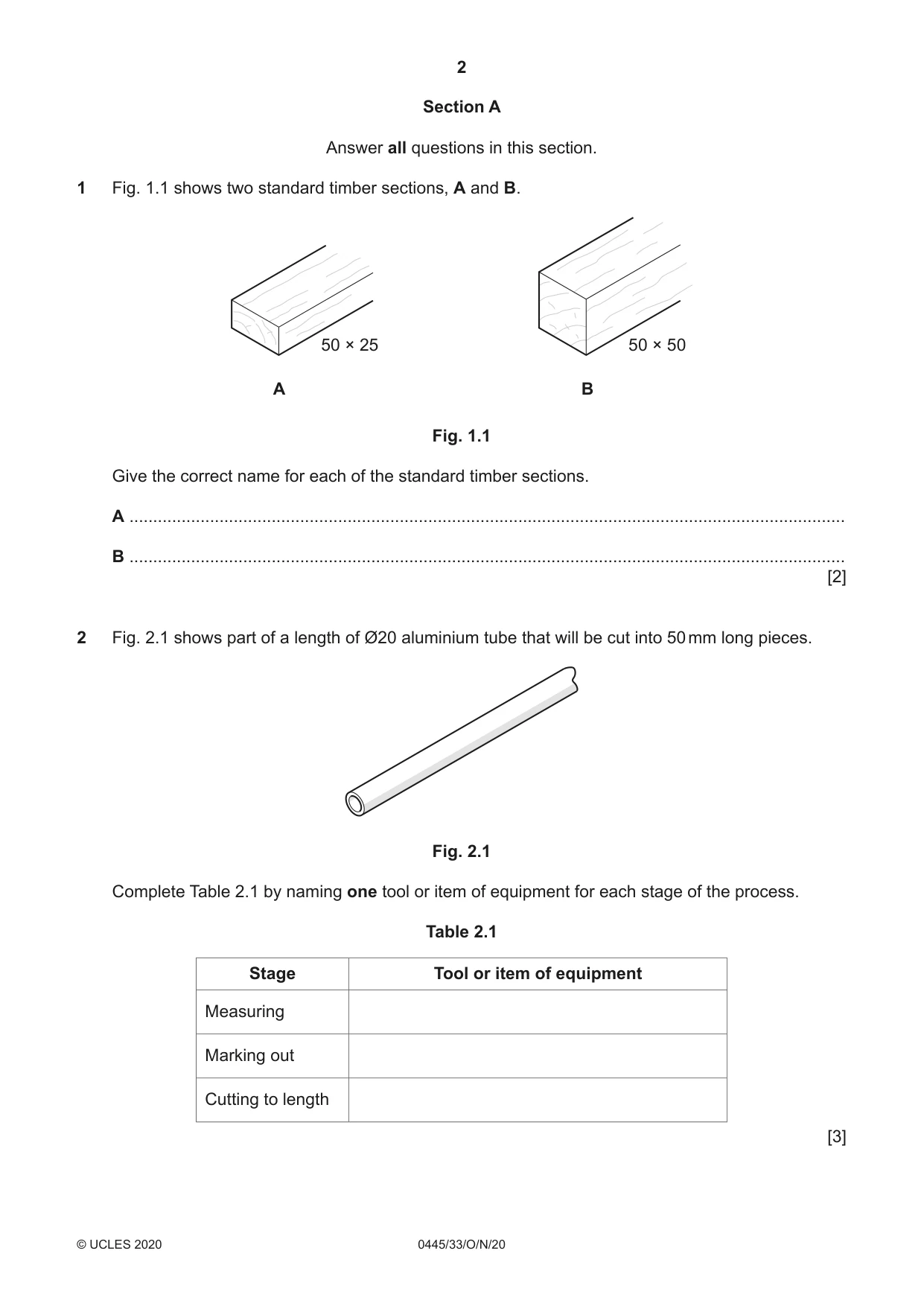
1 Fig. 1.1 shows two standard timber sections, A and B. 50 × 25 50 × 50 A B Fig. 1.1 Give the correct name for each of the standard timber sections. A ....................................................................................................................................................... B ....................................................................................................................................................... [2]
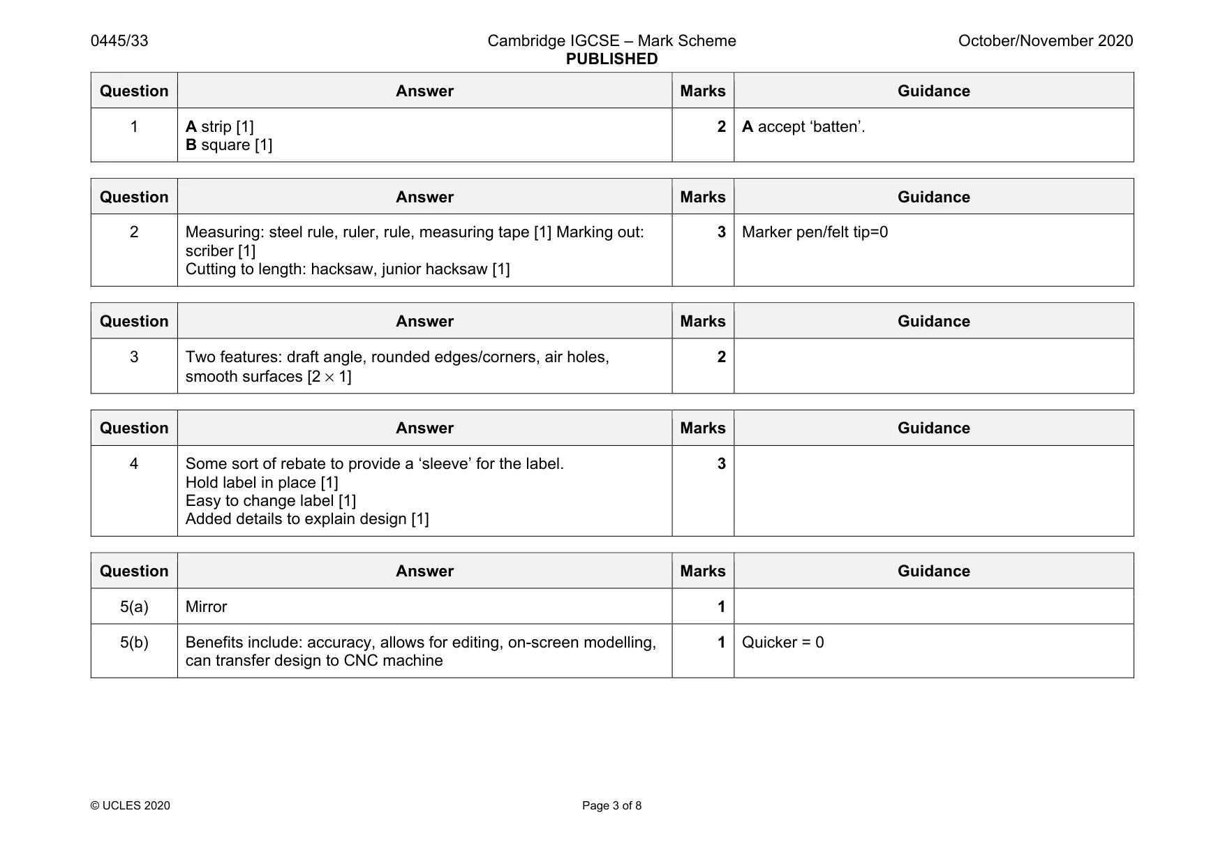
Mark scheme: 1 A strip [1] B square [1] 2 A accept ‘batten’.
Q2 · Part of a length of Ø20 aluminium tube that will be cut into 50 mm long pieces
2 Fig. 2.1 shows part of a length of Ø20 aluminium tube that will be cut into 50 mm long pieces. Fig. 2.1 Complete Table 2.1 by naming one tool or item of equipment for each stage of the process. Table 2.1 Stage Tool or item of equipment Measuring Marking out Cutting to length [3]
Mark scheme: 2 Measuring: steel rule, ruler, rule, measuring tape [1] Marking out: scriber [1] Cutting to length: hacksaw, junior hacksaw [1] 3 Marker pen/felt tip=0
Q3 · A former that will be used when vacuum forming plastic
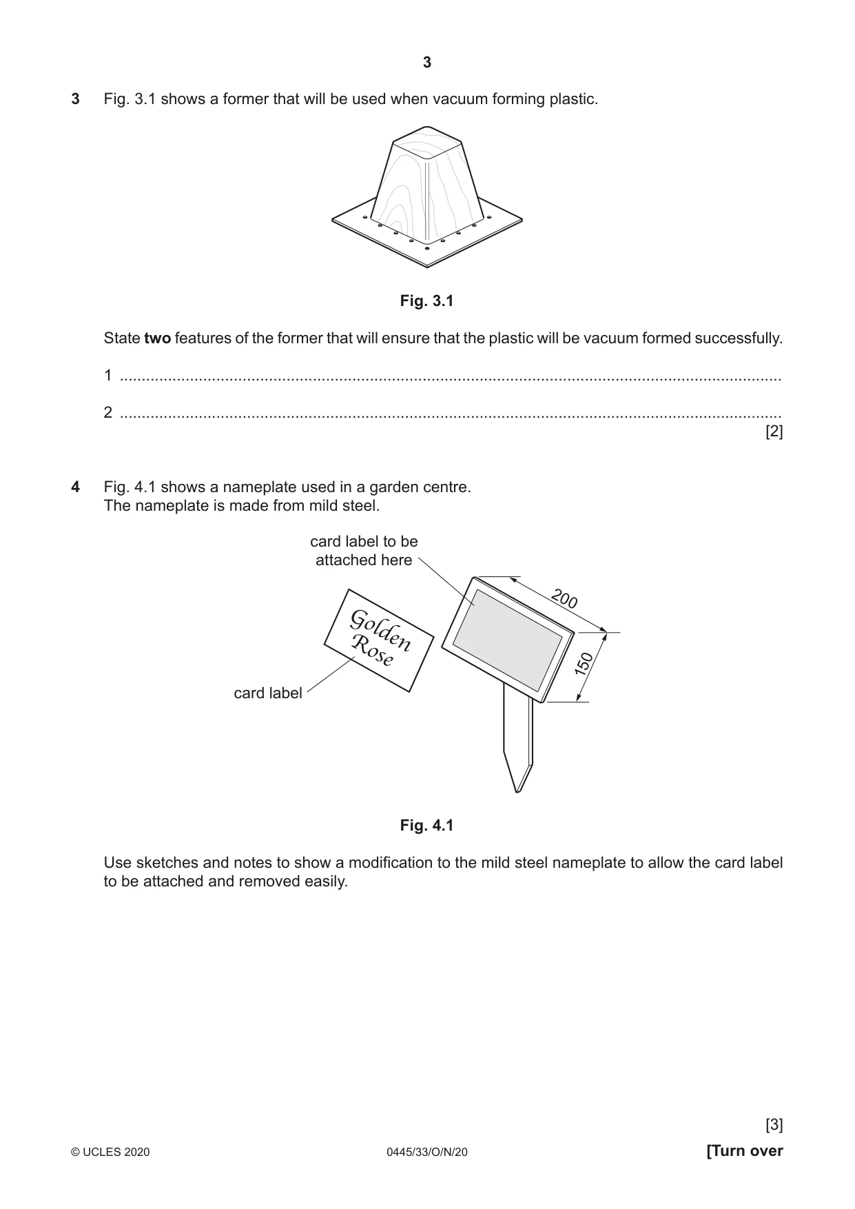
3 Fig. 3.1 shows a former that will be used when vacuum forming plastic. Fig. 3.1 State two features of the former that will ensure that the plastic will be vacuum formed successfully. 1 ....................................................................................................................................................... 2 ....................................................................................................................................................... [2]
Mark scheme: 3 Two features: draft angle, rounded edges/corners, air holes, smooth surfaces [2 × 1] 2
Q4 · A nameplate used in a garden centre
4 Fig. 4.1 shows a nameplate used in a garden centre. The nameplate is made from mild steel. card label to be attached here 200 Golden Rose 150 card label Fig. 4.1 Use sketches and notes to show a modification to the mild steel nameplate to allow the card label to be attached and removed easily. [3]
Mark scheme: 4 Some sort of rebate to provide a ‘sleeve’ for the label. Hold label in place [1] Easy to change label [1] Added details to explain design [1]
Q5 · A leaflet holder made from acrylic sheet
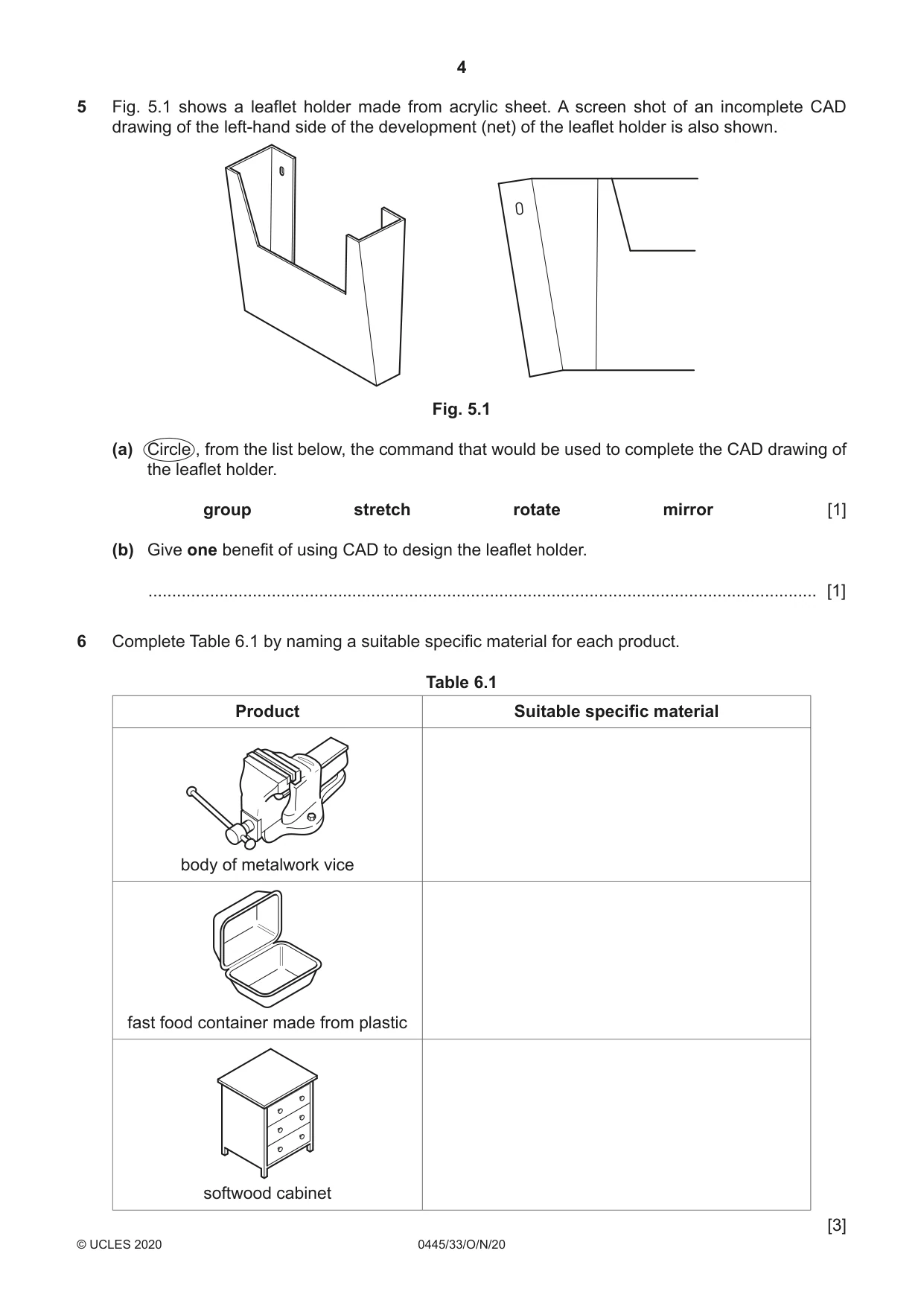
5 Fig. 5.1 shows a leaflet holder made from acrylic sheet. A screen shot of an incomplete CAD drawing of the left-hand side of the development (net) of the leaflet holder is also shown. Fig. 5.1 (a) Circle , from the list below, the command that would be used to complete the CAD drawing of the leaflet holder. group stretch rotate mirror [1] (b) Give one benefit of using CAD to design the leaflet holder. ............................................................................................................................................. [1]
Mark scheme: 5(a) Mirror 1 5(b) Benefits include: accuracy, allows for editing, on-screen modelling, can transfer design to CNC machine 1 Quicker = 0
Q6 · Complete Table 6.1 by naming a suitable specific material for each product
6 Complete Table 6.1 by naming a suitable specific material for each product. Table 6.1 Product Suitable specific material body of metalwork vice fast food container made from plastic softwood cabinet [3]
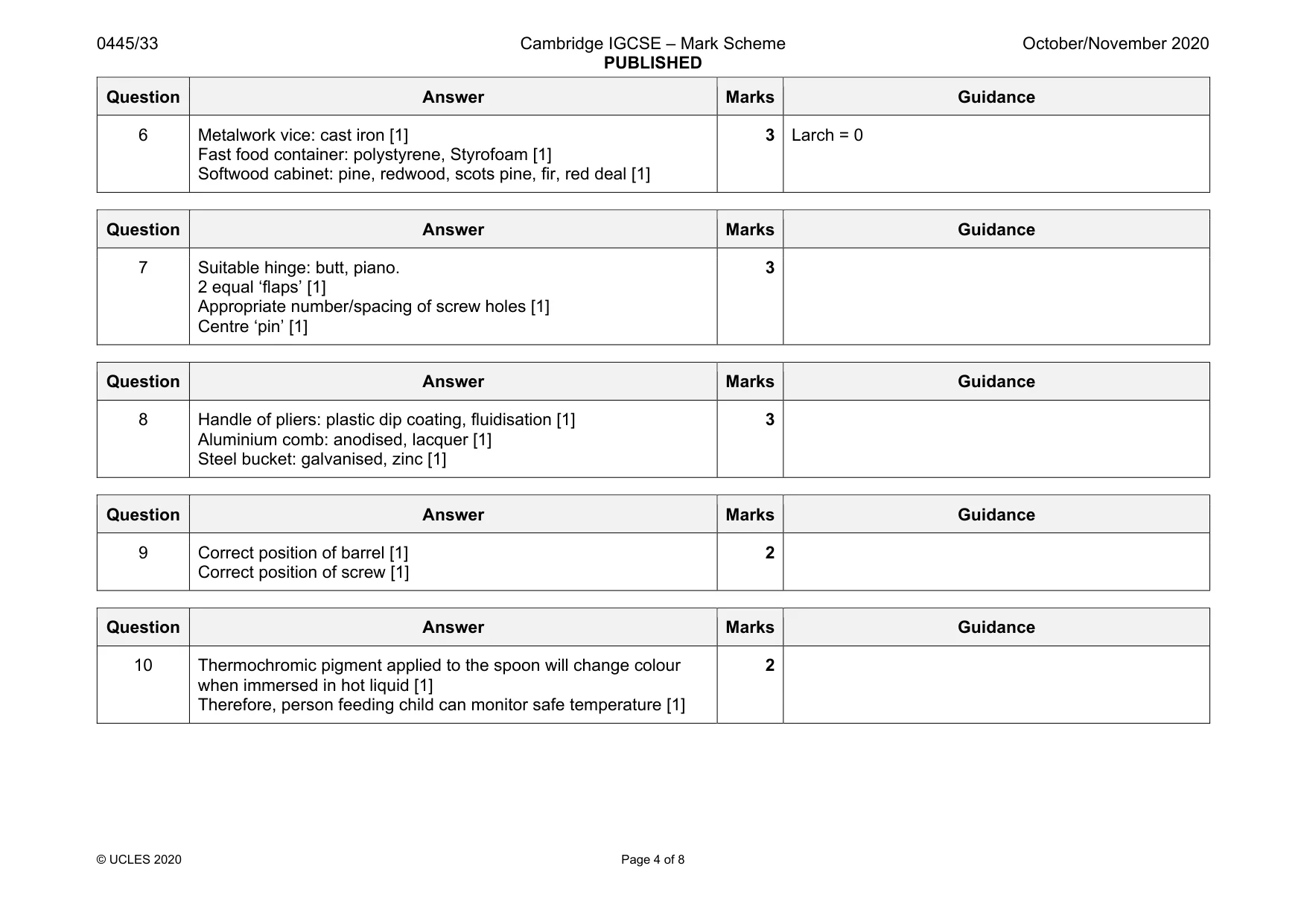
Mark scheme: 6 Metalwork vice: cast iron [1] Fast food container: polystyrene, Styrofoam [1] Softwood cabinet: pine, redwood, scots pine, fir, red deal [1] 3 Larch = 0
Question 7
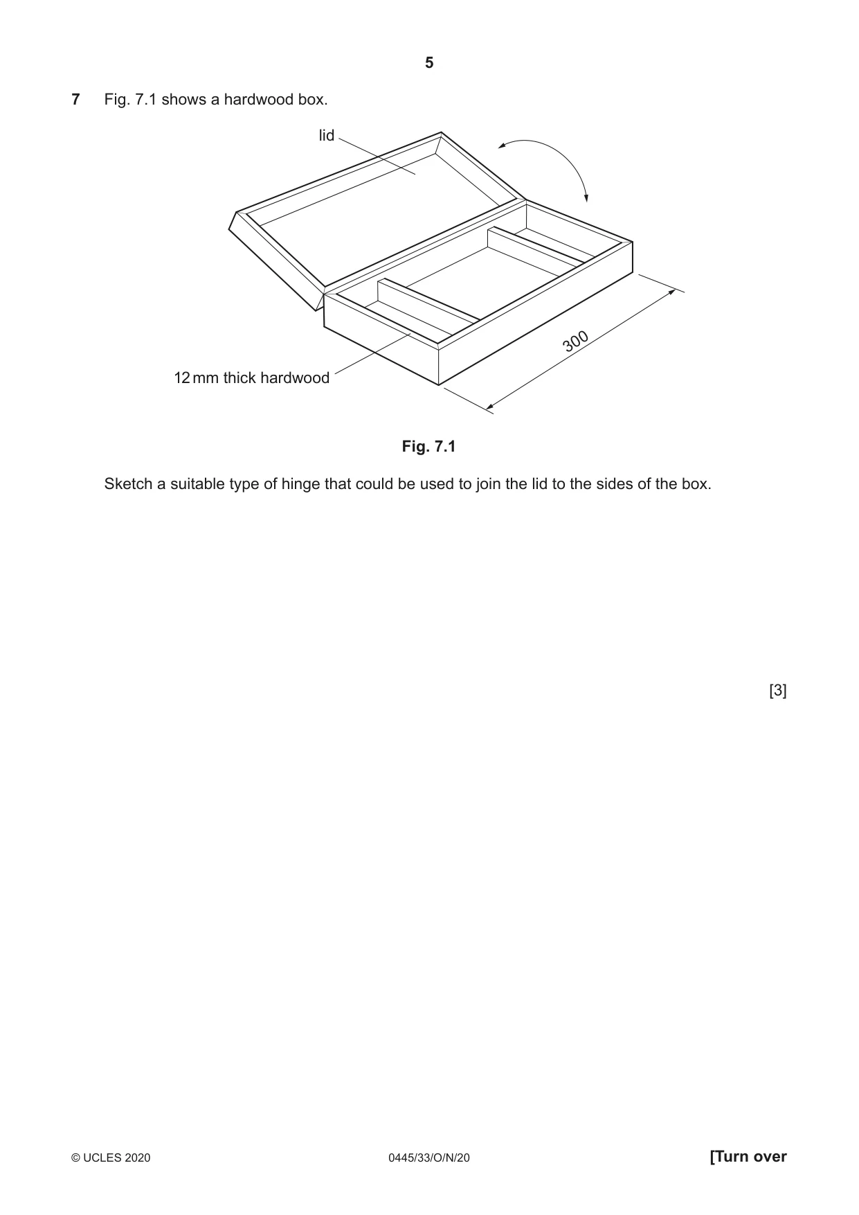
7 Fig. 7.1 shows a hardwood box. lid 300 12 mm thick hardwood Fig. 7.1 Sketch a suitable type of hinge that could be used to join the lid to the sides of the box. [3]
Mark scheme: 7 Suitable hinge: butt, piano. 2 equal ‘flaps’ [1] Appropriate number/spacing of screw holes [1] Centre ‘pin’ [1] 3
Q8 · Complete Table 8.1 by naming a suitable finish, other than paint, for each of the…
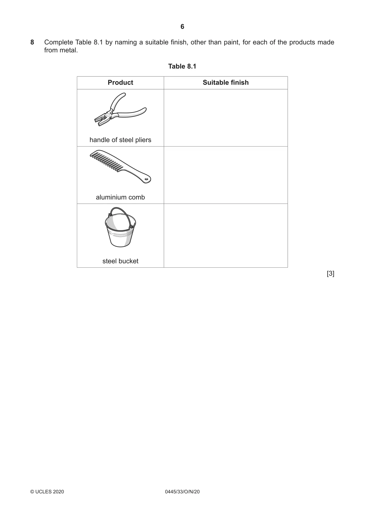
8 Complete Table 8.1 by naming a suitable finish, other than paint, for each of the products made from metal. Table 8.1 Product Suitable finish handle of steel pliers aluminium comb steel bucket [3]
Mark scheme: 8 Handle of pliers: plastic dip coating, fluidisation [1] Aluminium comb: anodised, lacquer [1] Steel bucket: galvanised, zinc [1] 3
Q9 · Details of a knock-down (KD) fitting
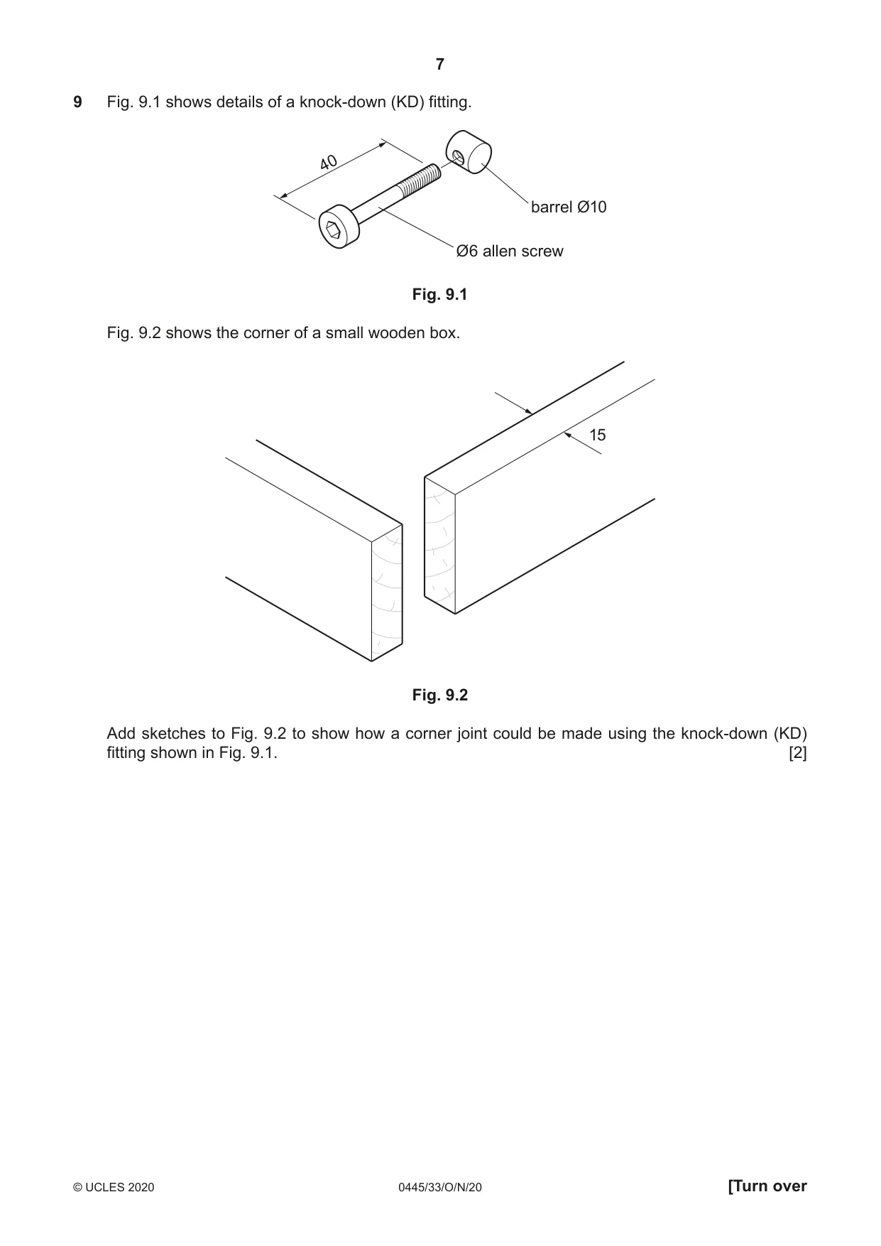
9 Fig. 9.1 shows details of a knock-down (KD) fitting. 40 barrel Ø10 Ø6 allen screw Fig. 9.1 Fig. 9.2 shows the corner of a small wooden box. 15 Fig. 9.2 Add sketches to Fig. 9.2 to show how a corner joint could be made using the knock-down (KD) fitting shown in Fig. 9.1. [2]
Mark scheme: 9 Correct position of barrel [1] Correct position of screw [1] 2
Q10 · A plastic fork and spoon used to feed very young children
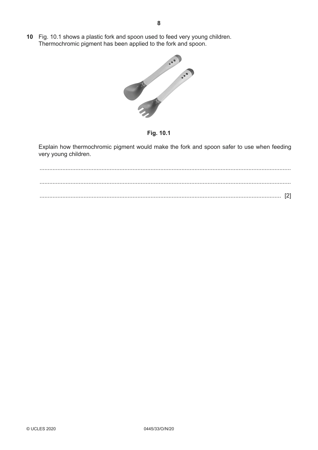
10 Fig. 10.1 shows a plastic fork and spoon used to feed very young children. Thermochromic pigment has been applied to the fork and spoon. Fig. 10.1 Explain how thermochromic pigment would make the fork and spoon safer to use when feeding very young children. .......................................................................................................................................................... .......................................................................................................................................................... .................................................................................................................................................... [2]
Mark scheme: 10 Thermochromic pigment applied to the spoon will change colour when immersed in hot liquid [1] Therefore, person feeding child can monitor safe temperature [1] 2
Q11 · Views of a small table made from 15 mm thick plywood
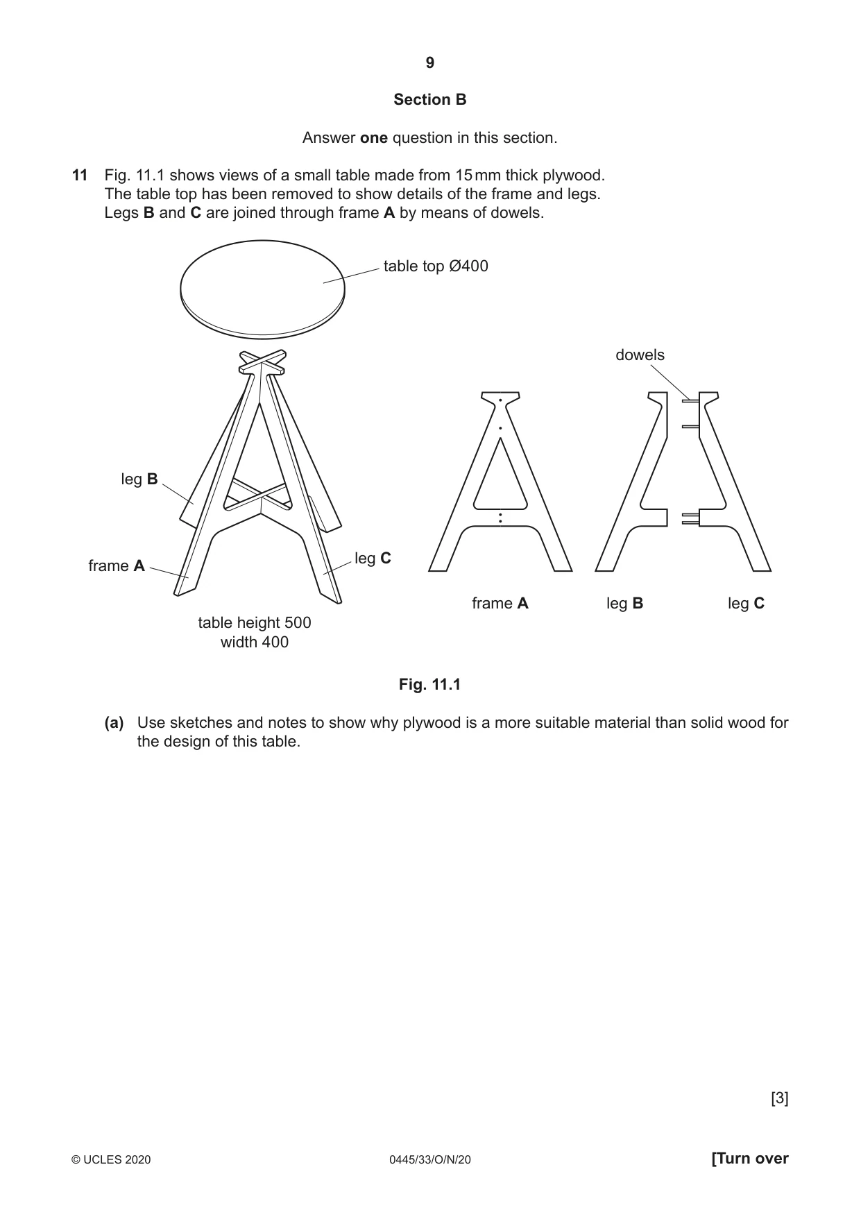
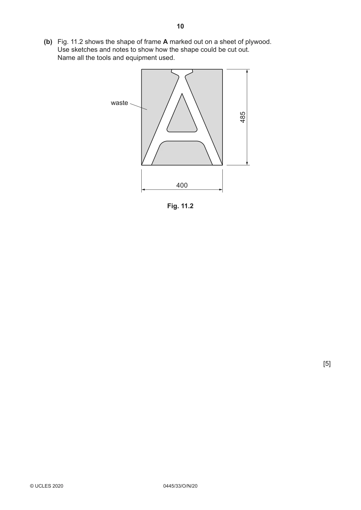
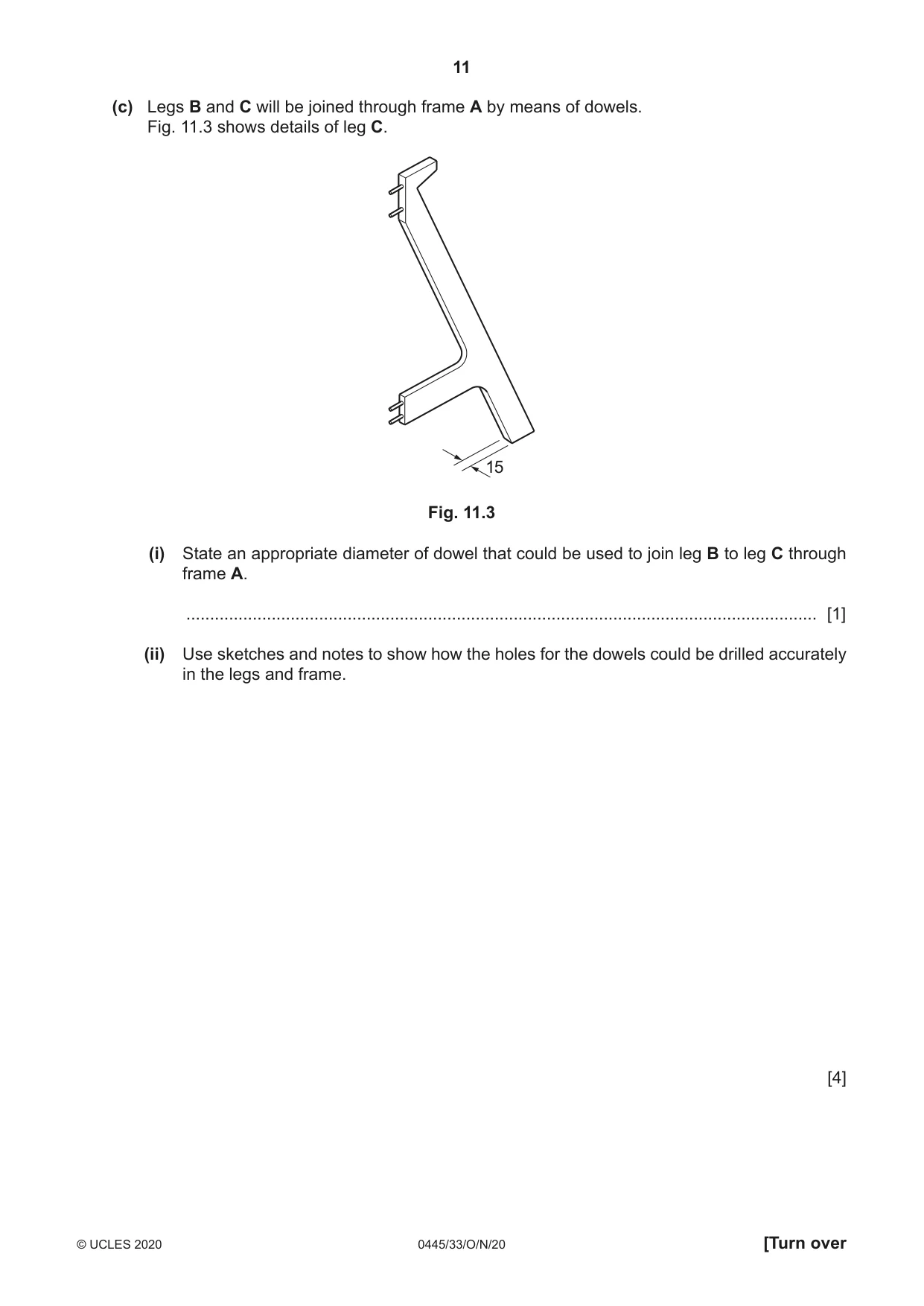
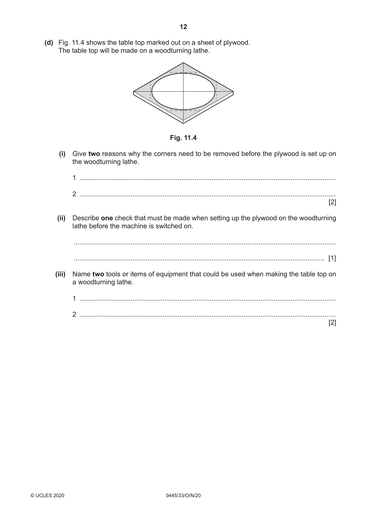
11 Fig. 11.1 shows views of a small table made from 15 mm thick plywood. The table top has been removed to show details of the frame and legs. Legs B and C are joined through frame A by means of dowels. table top Ø400 dowels leg B leg C frame A frame A leg B leg C table height 500 width 400 Fig. 11.1 (a) Use sketches and notes to show why plywood is a more suitable material than solid wood for the design of this table. [3] (b) Fig. 11.2 shows the shape of frame A marked out on a sheet of plywood. Use sketches and notes to show how the shape could be cut out. Name all the tools and equipment used. waste 485 400 Fig. 11.2 [5] (c) Legs B and C will be joined through frame A by means of dowels. Fig. 11.3 shows details of leg C. 15 Fig. 11.3 (i) State an appropriate diameter of dowel that could be used to join leg B to leg C through frame A. ..................................................................................................................................... [1] (ii) Use sketches and notes to show how the holes for the dowels could be drilled accurately in the legs and frame. [4] (d) Fig. 11.4 shows the table top marked out on a sheet of plywood. The table top will be made on a woodturning lathe. Fig. 11.4 (i) Give two reasons why the corners need to be removed before the plywood is set up on the woodturning lathe. 1 ........................................................................................................................................ 2 ........................................................................................................................................ [2] (ii) Describe one check that must be made when setting up the plywood on the woodturning lathe before the machine is switched on. ........................................................................................................................................... ..................................................................................................................................... [1] (iii) Name two tools or items of equipment that could be used when making the table top on a woodturning lathe. 1 ........................................................................................................................................ 2 ........................................................................................................................................ [2] (e) Use sketches and notes to show a method of fixing the table top to the frame and legs. Additional materials may be used. [4] (f) The table will have a painted finish. (i) Give one reason why the parts of the table would be painted before they are assembled. ..................................................................................................................................... [1] (ii) A primer coat will be applied first. Explain the purpose of a primer coat. ........................................................................................................................................... ........................................................................................................................................... ..................................................................................................................................... [2]
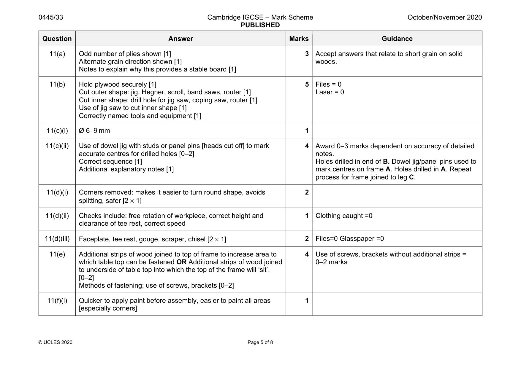
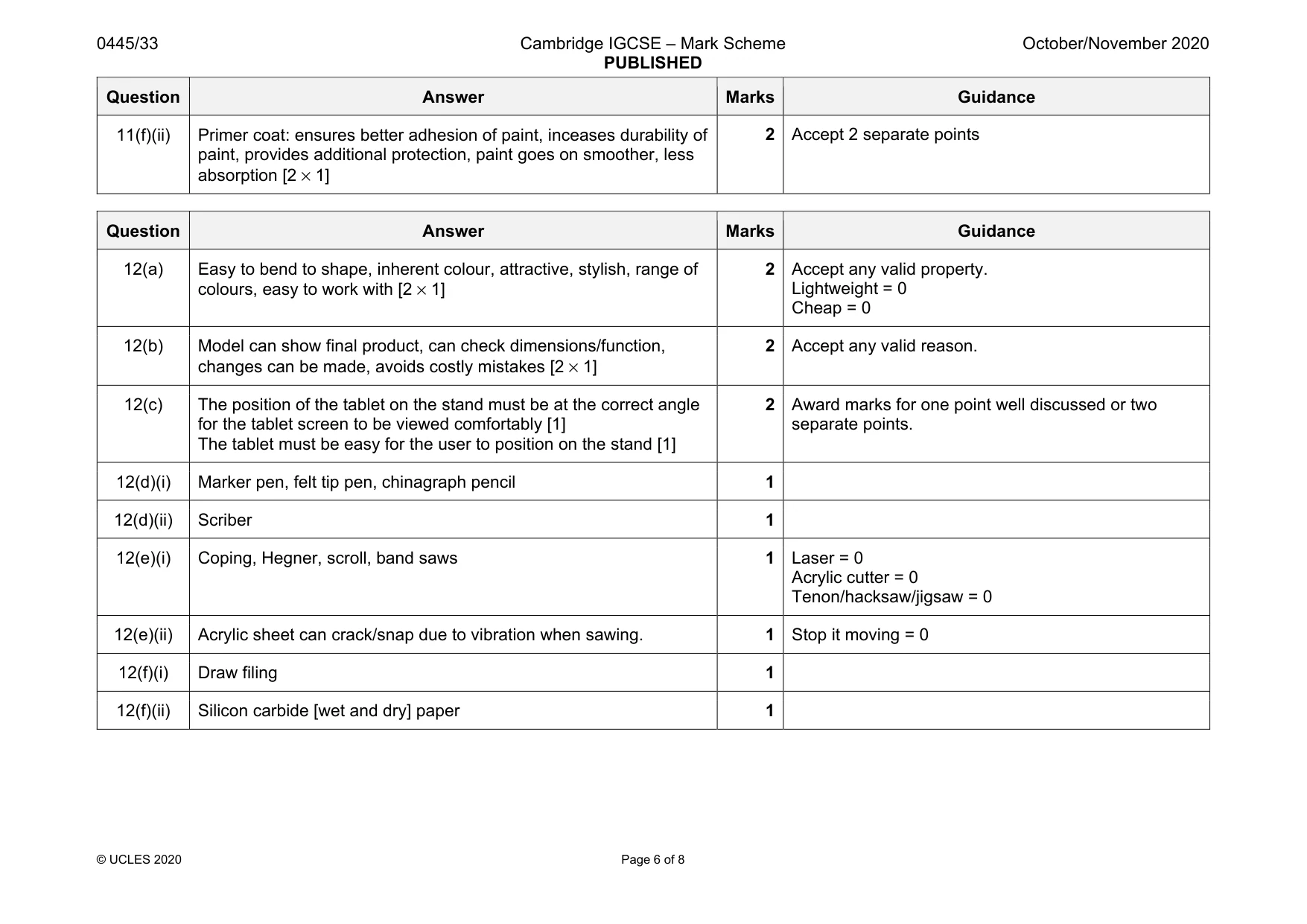
Mark scheme: 11(a) Odd number of plies shown [1] Alternate grain direction shown [1] Notes to explain why this provides a stable board [1] 3 Accept answers that relate to short grain on solid woods. 11(b) Hold plywood securely [1] Cut outer shape: jig, Hegner, scroll, band saws, router [1] Cut inner shape: drill hole for jig saw, coping saw, router [1] Use of jig saw to cut inner shape [1] Correctly named tools and equipment [1] 5 Files = 0 Laser = 0 11(c)(i) Ø 6–9 mm 1 11(c)(ii) Use of dowel jig with studs or panel pins [heads cut off] to mark accurate centres for drilled holes [0–2] Correct sequence [1] Additional explanatory notes [1] 4 Award 0–3 marks dependent on accuracy of detailed notes. Holes drilled in end of B. Dowel jig/panel pins used to mark centres on frame A. Holes drilled in A. Repeat process for frame joined to leg C. 11(d)(i) Corners removed: makes it easier to turn round shape, avoids splitting, safer [2 × 1] 2 11(d)(ii) Checks include: free rotation of workpiece, correct height and clearance of tee rest, correct speed 1 Clothing caught =0 11(d)(iii) Faceplate, tee rest, gouge, scraper, chisel [2 × 1] 2 Files=0 Glasspaper =0 11(e) Additional strips of wood joined to top of frame to increase area to which table top can be fastened OR Additional strips of wood joined to underside of table top into which the top of the frame will ‘sit’. [0–2] Methods of fastening; use of screws, brackets [0–2] 4 Use of screws, brackets without additional strips = 0–2 marks 11(f)(i) Quicker to apply paint before assembly, easier to paint all areas [especially corners] 1 Question Answer Marks Guidance 11(f)(ii) Primer coat: ensures better adhesion of paint, inceases durability of paint, provides additional protection, paint goes on smoother, less absorption [2 × 1] 2 Accept 2 separate points
Q12 · Views of an incomplete design of a stand for a tablet
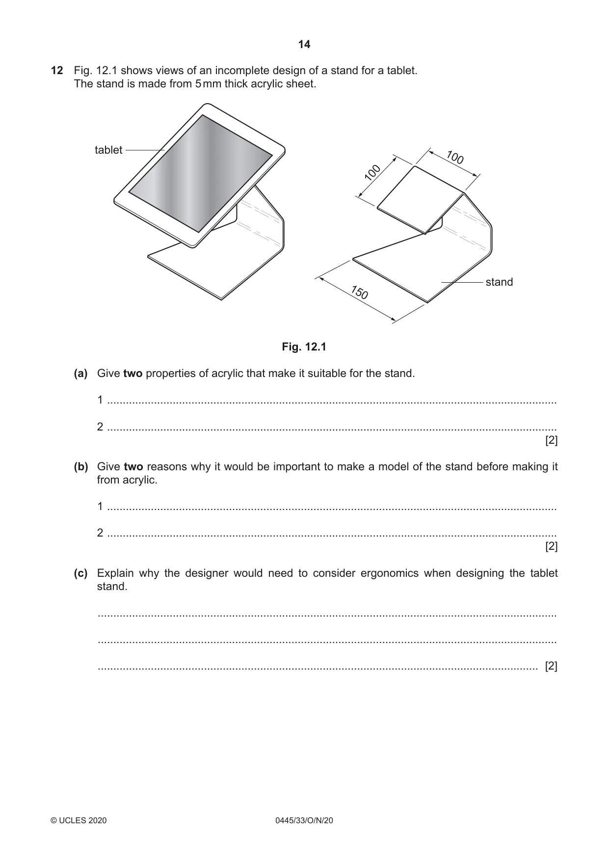
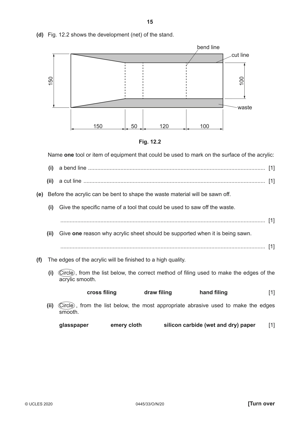
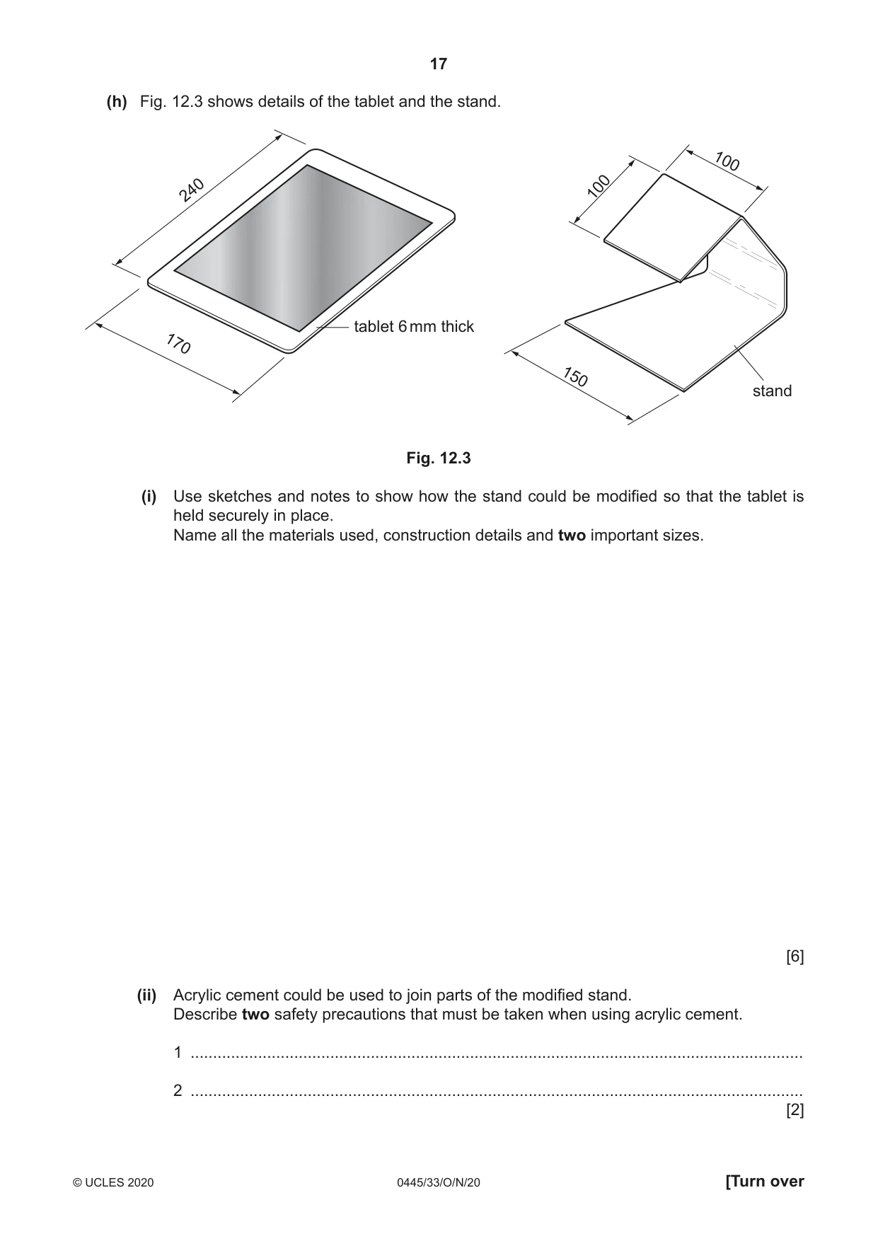
12 Fig. 12.1 shows views of an incomplete design of a stand for a tablet. The stand is made from 5 mm thick acrylic sheet. tablet 100 100 stand 150 Fig. 12.1 (a) Give two properties of acrylic that make it suitable for the stand. 1 ................................................................................................................................................ 2 ................................................................................................................................................ [2] (b) Give two reasons why it would be important to make a model of the stand before making it from acrylic. 1 ................................................................................................................................................ 2 ................................................................................................................................................ [2] (c) Explain why the designer would need to consider ergonomics when designing the tablet stand. ................................................................................................................................................... ................................................................................................................................................... ............................................................................................................................................. [2] (d) Fig. 12.2 shows the development (net) of the stand. bend line cut line 150 100 waste 150 50 120 100 Fig. 12.2 Name one tool or item of equipment that could be used to mark on the surface of the acrylic: (i) a bend line ................................................................................................................... [1] (ii) a cut line ...................................................................................................................... [1] (e) Before the acrylic can be bent to shape the waste material will be sawn off. (i) Give the specific name of a tool that could be used to saw off the waste. ..................................................................................................................................... [1] (ii) Give one reason why acrylic sheet should be supported when it is being sawn. ..................................................................................................................................... [1] (f) The edges of the acrylic will be finished to a high quality. (i) Circle , from the list below, the correct method of filing used to make the edges of the acrylic smooth. cross filing draw filing hand filing [1] (ii) Circle , from the list below, the most appropriate abrasive used to make the edges smooth. glasspaper emery cloth silicon carbide (wet and dry) paper [1] (g) Use sketches and notes to show how the acrylic could be bent to shape. Include details of: • the method of heating the acrylic • the method of bending the acrylic • the method of retaining the acrylic while it cools • the sequence in which the bends will be produced. [5] (h) Fig. 12.3 shows details of the tablet and the stand. 100 240 100 tablet 6 mm thick 170 150 stand Fig. 12.3 (i) Use sketches and notes to show how the stand could be modified so that the tablet is held securely in place. Name all the materials used, construction details and two important sizes. [6] (ii) Acrylic cement could be used to join parts of the modified stand. Describe two safety precautions that must be taken when using acrylic cement. 1 ........................................................................................................................................ 2 ........................................................................................................................................ [2]
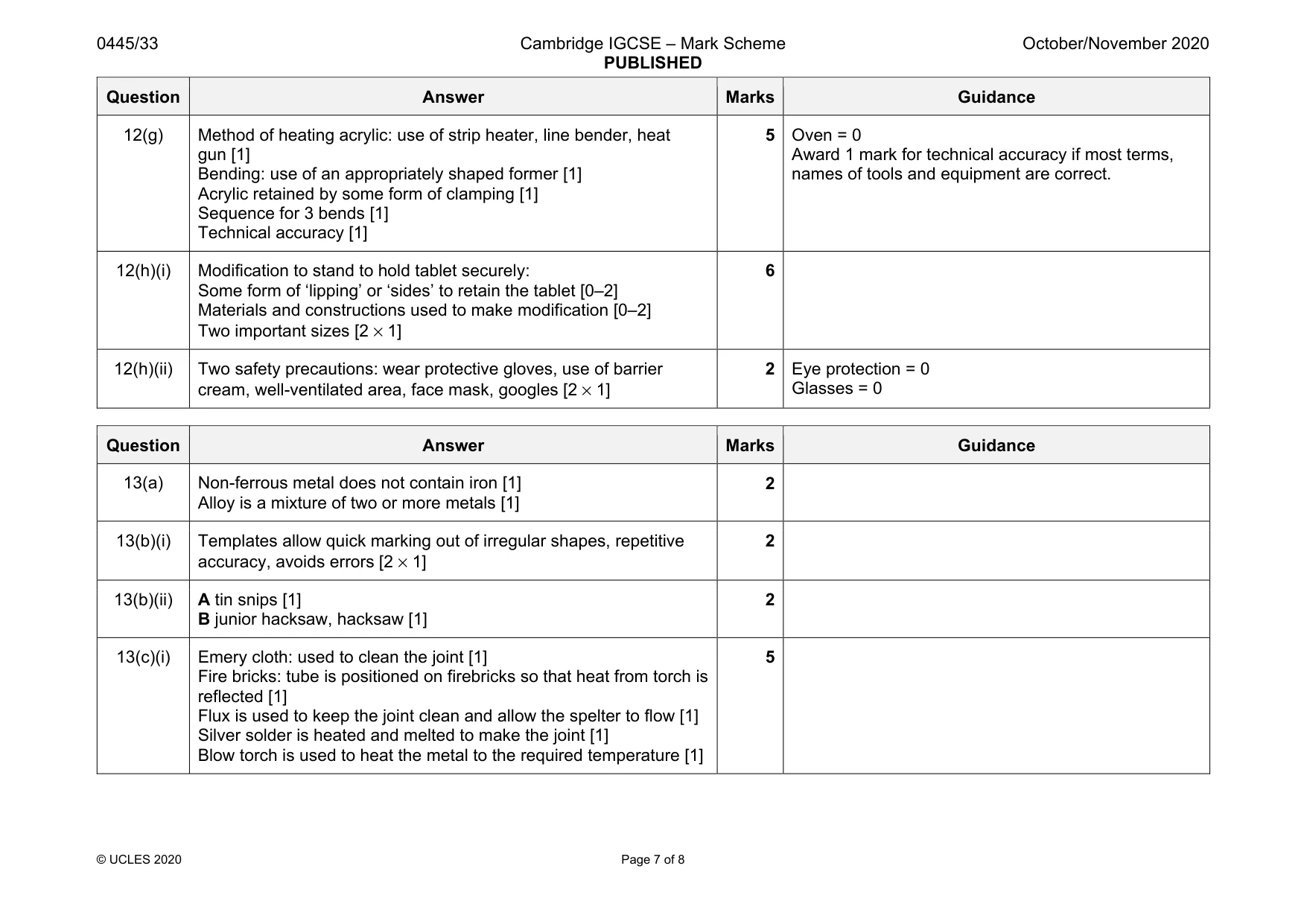
Mark scheme: 12(a) Easy to bend to shape, inherent colour, attractive, stylish, range of colours, easy to work with [2 × 1] 2 Accept any valid property. Lightweight = 0 Cheap = 0 12(b) Model can show final product, can check dimensions/function, changes can be made, avoids costly mistakes [2 × 1] 2 Accept any valid reason. 12(c) The position of the tablet on the stand must be at the correct angle for the tablet screen to be viewed comfortably [1] The tablet must be easy for the user to position on the stand [1] 2 Award marks for one point well discussed or two separate points. 12(d)(i) Marker pen, felt tip pen, chinagraph pencil 1 12(d)(ii) Scriber 1 12(e)(i) Coping, Hegner, scroll, band saws 1 Laser = 0 Acrylic cutter = 0 Tenon/hacksaw/jigsaw = 0 12(e)(ii) Acrylic sheet can crack/snap due to vibration when sawing. 1 Stop it moving = 0 12(f)(i) Draw filing 1 12(f)(ii) Silicon carbide [wet and dry] paper 1 Question Answer Marks Guidance 12(g) Method of heating acrylic: use of strip heater, line bender, heat gun [1] Bending: use of an appropriately shaped former [1] Acrylic retained by some form of clamping [1] Sequence for 3 bends [1] Technical accuracy [1] 5 Oven = 0 Award 1 mark for technical accuracy if most terms, names of tools and equipment are correct. 12(h)(i) Modification to stand to hold tablet securely: Some form of ‘lipping’ or ‘sides’ to retain the tablet [0–2] Materials and constructions used to make modification [0–2] Two important sizes [2 × 1] 6 12(h)(ii) Two safety precautions: wear protective gloves, use of barrier cream, well-ventilated area, face mask, googles [2 × 1] 2 Eye protection = 0 Glasses = 0
Q13 · A table lamp that could be made in a school workshop
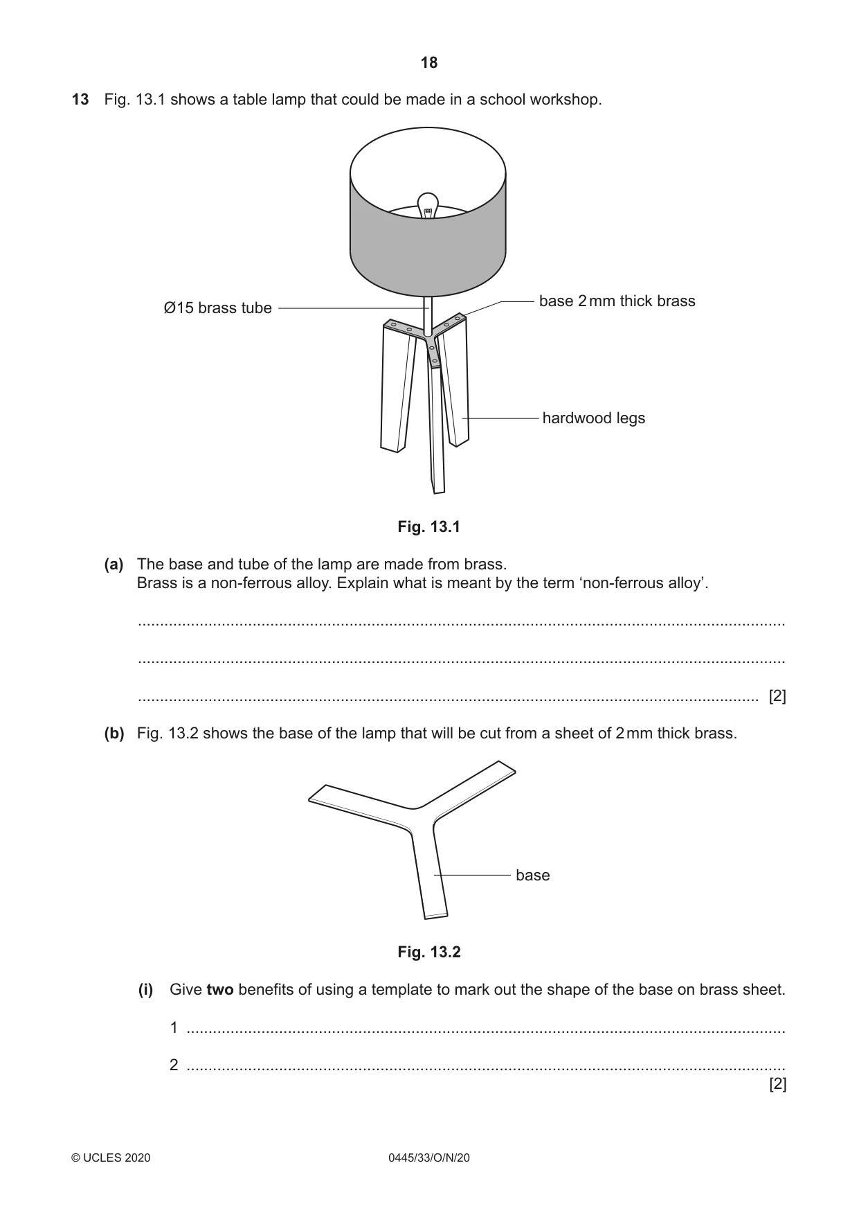
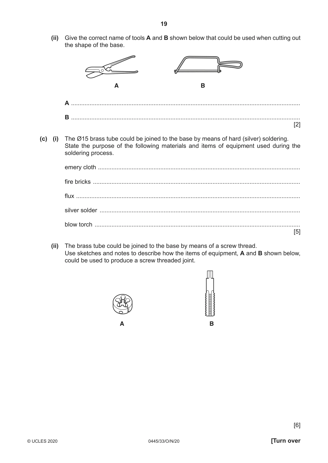
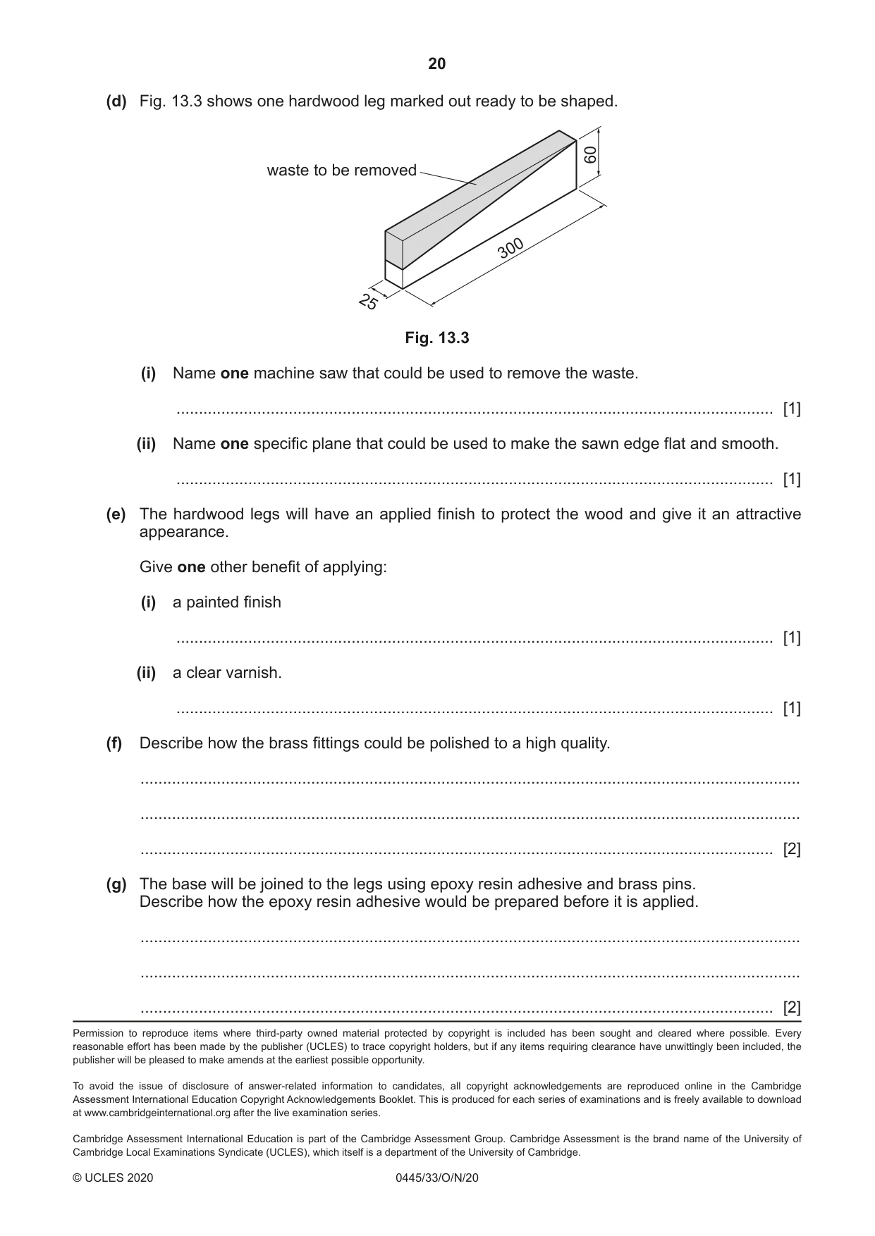
13 Fig. 13.1 shows a table lamp that could be made in a school workshop. base 2 mm thick brass Ø15 brass tube hardwood legs Fig. 13.1 (a) The base and tube of the lamp are made from brass. Brass is a non-ferrous alloy. Explain what is meant by the term ‘non-ferrous alloy’. ................................................................................................................................................... ................................................................................................................................................... ............................................................................................................................................. [2] (b) Fig. 13.2 shows the base of the lamp that will be cut from a sheet of 2 mm thick brass. base Fig. 13.2 (i) Give two benefits of using a template to mark out the shape of the base on brass sheet. 1 ........................................................................................................................................ 2 ........................................................................................................................................ [2] (ii) Give the correct name of tools A and B shown below that could be used when cutting out the shape of the base. A B A ........................................................................................................................................ B ........................................................................................................................................ [2] (c) (i) The Ø15 brass tube could be joined to the base by means of hard (silver) soldering. State the purpose of the following materials and items of equipment used during the soldering process. emery cloth ........................................................................................................................ fire bricks ........................................................................................................................... flux ..................................................................................................................................... silver solder ....................................................................................................................... blow torch .......................................................................................................................... [5] (ii) The brass tube could be joined to the base by means of a screw thread. Use sketches and notes to describe how the items of equipment, A and B shown below, could be used to produce a screw threaded joint. A B [6] (d) Fig. 13.3 shows one hardwood leg marked out ready to be shaped. 60 waste to be removed 300 25 Fig. 13.3 (i) Name one machine saw that could be used to remove the waste. ..................................................................................................................................... [1] (ii) Name one specific plane that could be used to make the sawn edge flat and smooth. ..................................................................................................................................... [1] (e) The hardwood legs will have an applied finish to protect the wood and give it an attractive appearance. Give one other benefit of applying: (i) a painted finish ..................................................................................................................................... [1] (ii) a clear varnish. ..................................................................................................................................... [1] (f) Describe how the brass fittings could be polished to a high quality. ................................................................................................................................................... ................................................................................................................................................... ............................................................................................................................................. [2] (g) The base will be joined to the legs using epoxy resin adhesive and brass pins. Describe how the epoxy resin adhesive would be prepared before it is applied. ................................................................................................................................................... ................................................................................................................................................... ............................................................................................................................................. [2]
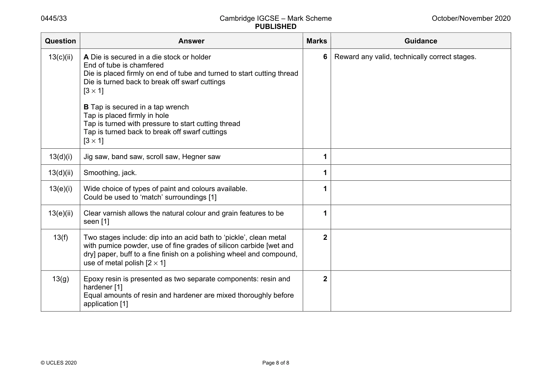
Mark scheme: 13(a) Non-ferrous metal does not contain iron [1] Alloy is a mixture of two or more metals [1] 2 13(b)(i) Templates allow quick marking out of irregular shapes, repetitive accuracy, avoids errors [2 × 1] 2 13(b)(ii) A tin snips [1] B junior hacksaw, hacksaw [1] 2 13(c)(i) Emery cloth: used to clean the joint [1] Fire bricks: tube is positioned on firebricks so that heat from torch is reflected [1] Flux is used to keep the joint clean and allow the spelter to flow [1] Silver solder is heated and melted to make the joint [1] Blow torch is used to heat the metal to the required temperature [1] 5 Question Answer Marks Guidance 13(c)(ii) A Die is secured in a die stock or holder End of tube is chamfered Die is placed firmly on end of tube and turned to start cutting thread Die is turned back to break off swarf cuttings [3 × 1] B Tap is secured in a tap wrench Tap is placed firmly in hole Tap is turned with pressure to start cutting thread Tap is turned back to break off swarf cuttings [3 × 1] 6 Reward any valid, technically correct stages. 13(d)(i) Jig saw, band saw, scroll saw, Hegner saw 1 13(d)(ii) Smoothing, jack. 1 13(e)(i) Wide choice of types of paint and colours available. Could be used to ‘match’ surroundings [1] 1 13(e)(ii) Clear varnish allows the natural colour and grain features to be seen [1] 1 13(f) Two stages include: dip into an acid bath to ‘pickle’, clean metal with pumice powder, use of fine grades of silicon carbide [wet and dry] paper, buff to a fine finish on a polishing wheel and compound, use of metal polish [2 × 1] 2 13(g) Epoxy resin is presented as two separate components: resin and hardener [1] Equal amounts of resin and hardener are mixed thoroughly before application [1] 2
What was in this paper
The subtopics covered by these 13 questions, and how many questions each got. Open one in a new tab to see every Cambridge question on it.
What you needed in this session
Cambridge’s own grade thresholds for 2020 Oct/Nov, Paper 3 · Variant 3. A higher threshold means an easier paper — the bar moves with how the cohort did.