Cambridge IGCSE Design and Technology 0445 — 2020 May/June Paper 3 · Variant 2
0445/32/M/J/20 · 13 questions · 100 marks · ≈113 min
The question paper and its mark scheme, free to read here and free to download. This is Cambridge’s own paper, exactly as it was sat.
Question paper20 pages
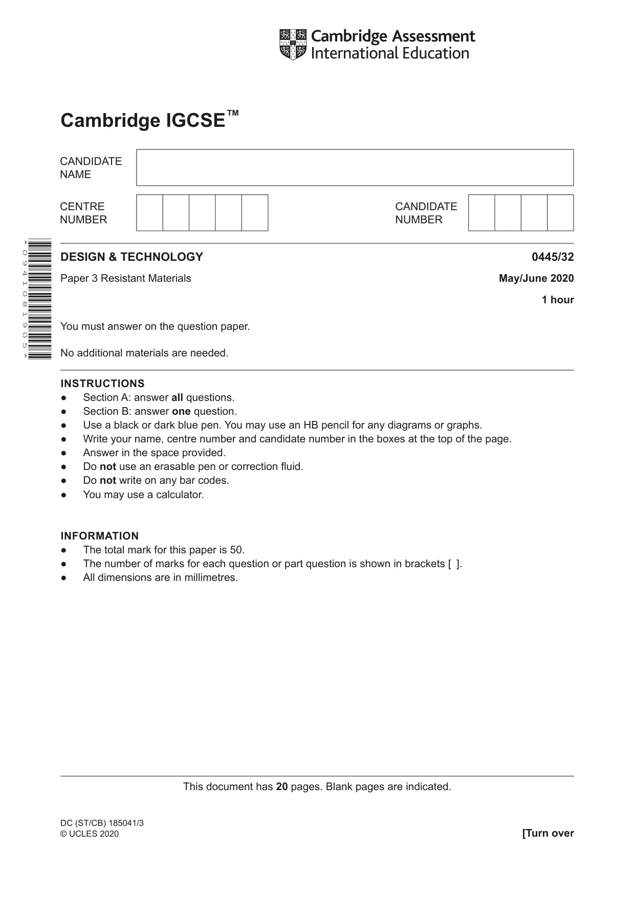
Mark scheme6 pages
Answers below. Sit the paper first if you are practising.
Questions as text
Q1 · Complete Table 1.1 by naming each of the tools that are used to mark out metal
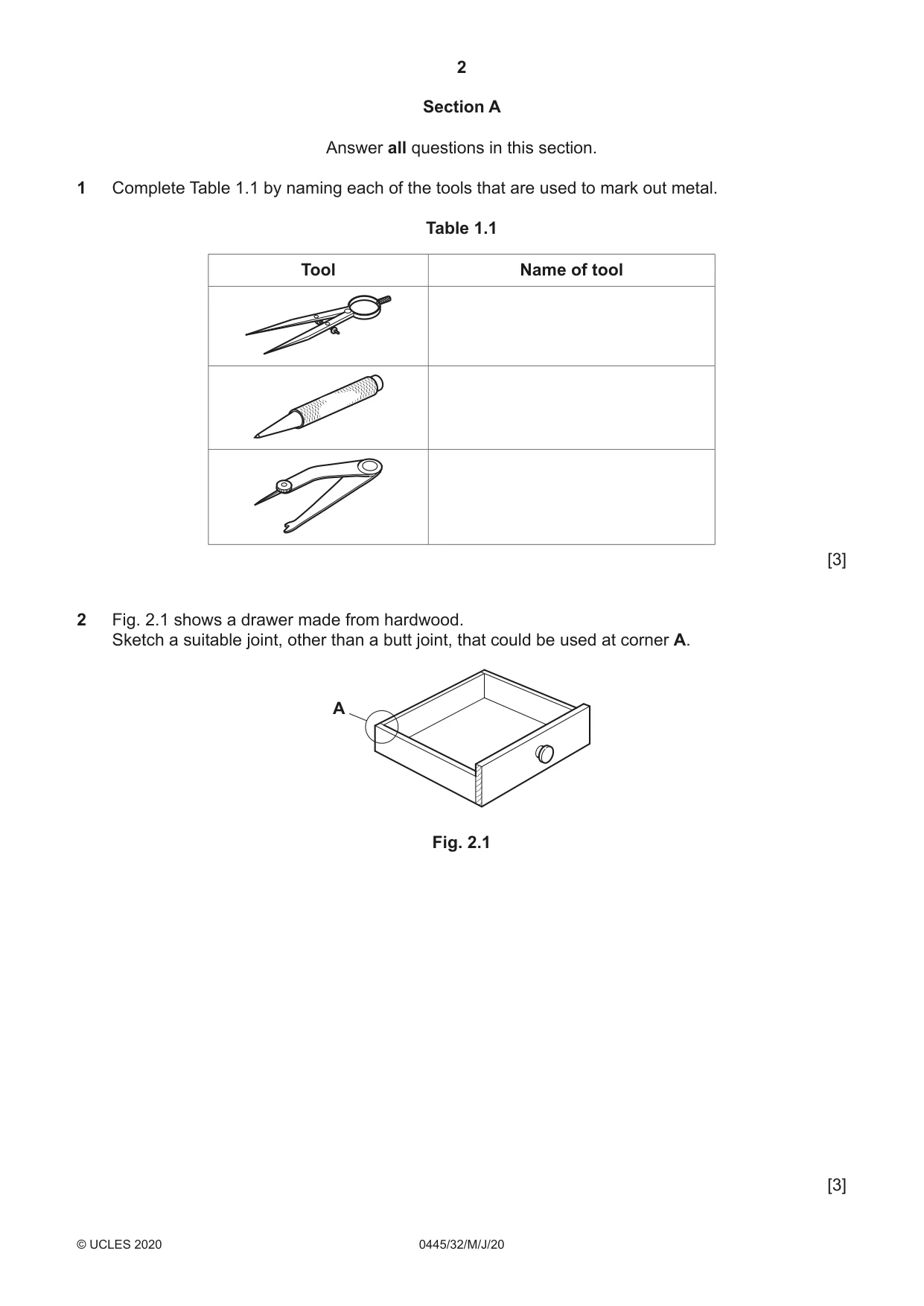
1 Complete Table 1.1 by naming each of the tools that are used to mark out metal. Table 1.1 Tool Name of tool [3]
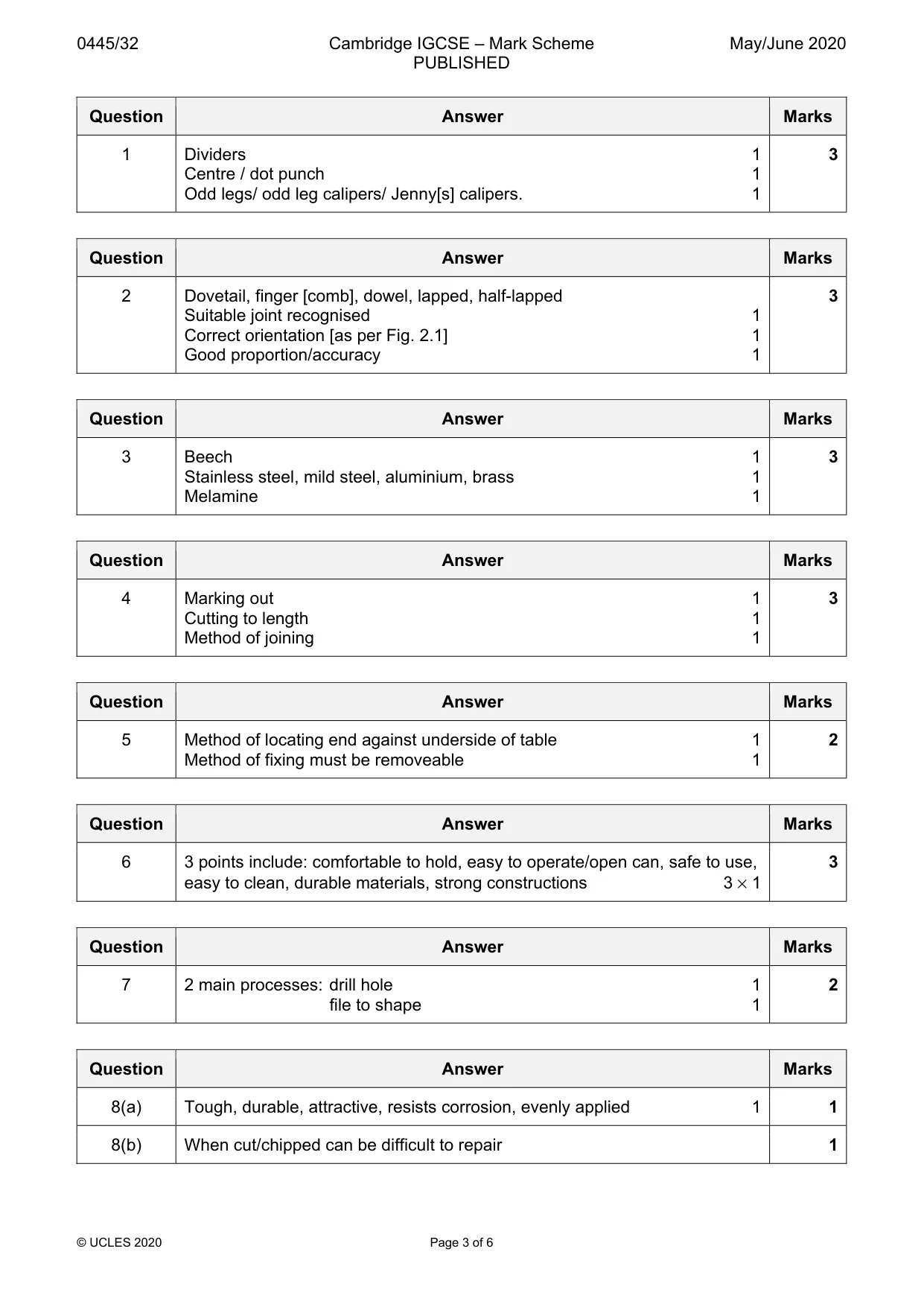
Mark scheme: Question Answer Marks 1 Dividers 1 3 Centre / dot punch 1 Odd legs/ odd leg calipers/ Jenny[s] calipers. 1
Q2 · A drawer made from hardwood
2 Fig. 2.1 shows a drawer made from hardwood. Sketch a suitable joint, other than a butt joint, that could be used at corner A. A Fig. 2.1 [3]
Mark scheme: 2 Dovetail, finger [comb], dowel, lapped, half-lapped 3 Suitable joint recognised 1 Correct orientation [as per Fig. 2.1] 1 Good proportion/accuracy 1
Q3 · Complete Table 3.1 by naming a suitable material for each product
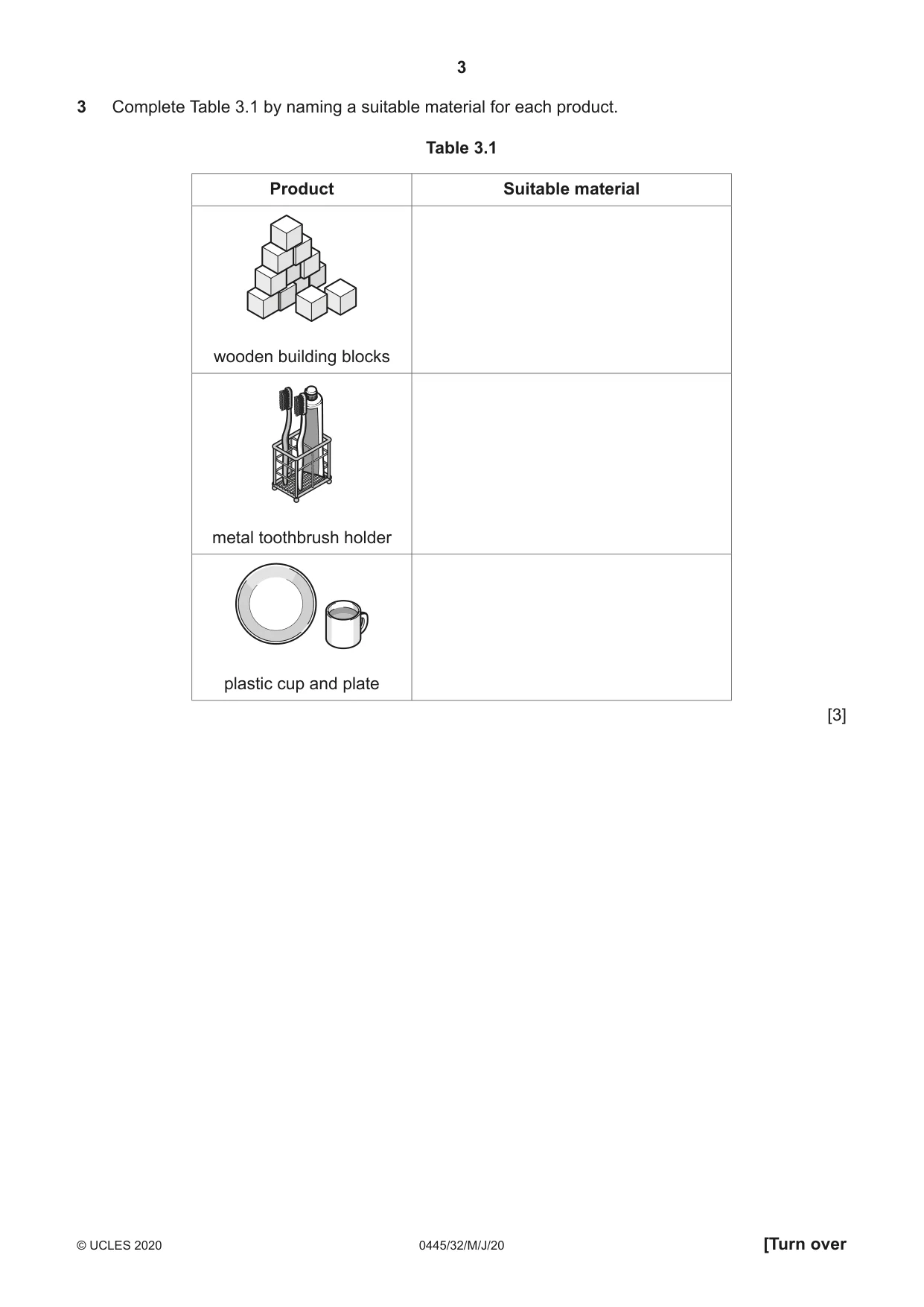
3 Complete Table 3.1 by naming a suitable material for each product. Table 3.1 Product Suitable material wooden building blocks metal toothbrush holder plastic cup and plate [3]
Mark scheme: 3 Beech 1 3 Stainless steel, mild steel, aluminium, brass 1 Melamine 1
Q4 · Details of a shelf bracket and a length of softwood from which the bracket is made
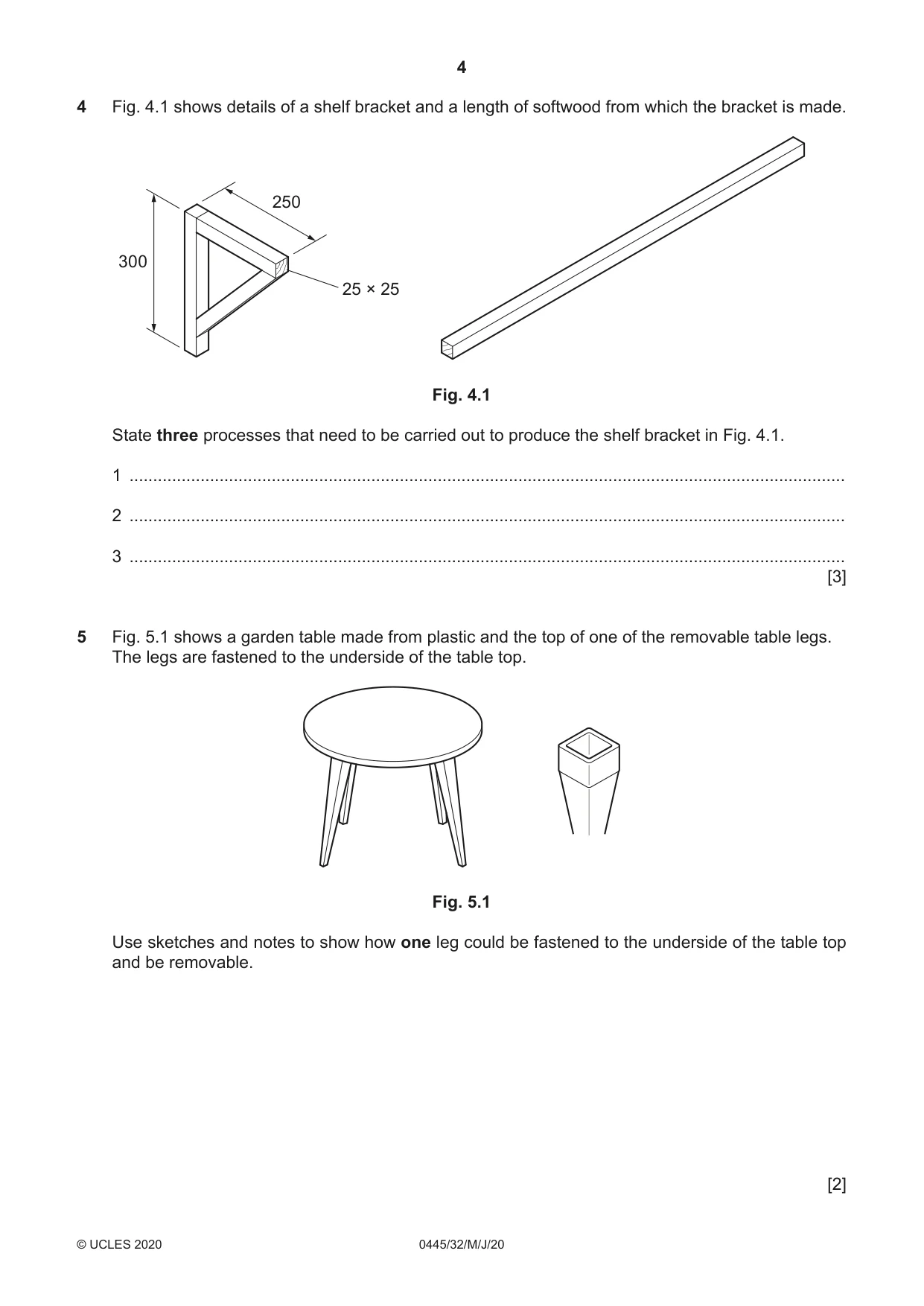
4 Fig. 4.1 shows details of a shelf bracket and a length of softwood from which the bracket is made. 250 300 25 × 25 Fig. 4.1 State three processes that need to be carried out to produce the shelf bracket in Fig. 4.1. 1 ....................................................................................................................................................... 2 ....................................................................................................................................................... 3 ....................................................................................................................................................... [3]
Mark scheme: 4 Marking out 1 3 Cutting to length 1 Method of joining 1
Q5 · A garden table made from plastic and the top of one of the removable table legs
5 Fig. 5.1 shows a garden table made from plastic and the top of one of the removable table legs. The legs are fastened to the underside of the table top. Fig. 5.1 Use sketches and notes to show how one leg could be fastened to the underside of the table top and be removable. [2]
Mark scheme: 5 Method of locating end against underside of table 1 2 Method of fixing must be removeable 1
Q6 · A can opener in use
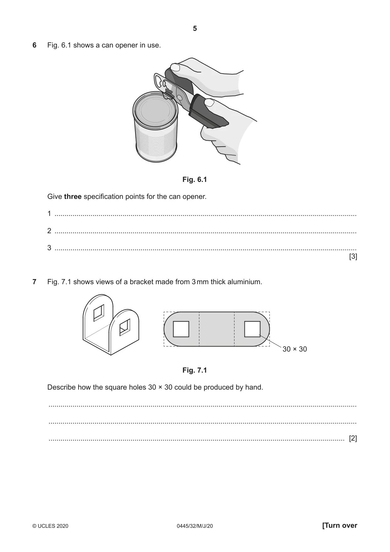
6 Fig. 6.1 shows a can opener in use. Fig. 6.1 Give three specification points for the can opener. 1 ....................................................................................................................................................... 2 ....................................................................................................................................................... 3 ....................................................................................................................................................... [3]
Mark scheme: 6 3 points include: comfortable to hold, easy to operate/open can, safe to use, 3 easy to clean, durable materials, strong constructions 3 × 1
Q7 · Views of a bracket made from 3 mm thick aluminium
7 Fig. 7.1 shows views of a bracket made from 3 mm thick aluminium. 30 × 30 Fig. 7.1 Describe how the square holes 30 × 30 could be produced by hand. .......................................................................................................................................................... .......................................................................................................................................................... .................................................................................................................................................... [2]
Mark scheme: 7 2 main processes: drill hole 1 2 file to shape 1
Q8 · A draining rack used for drying crockery and cutlery
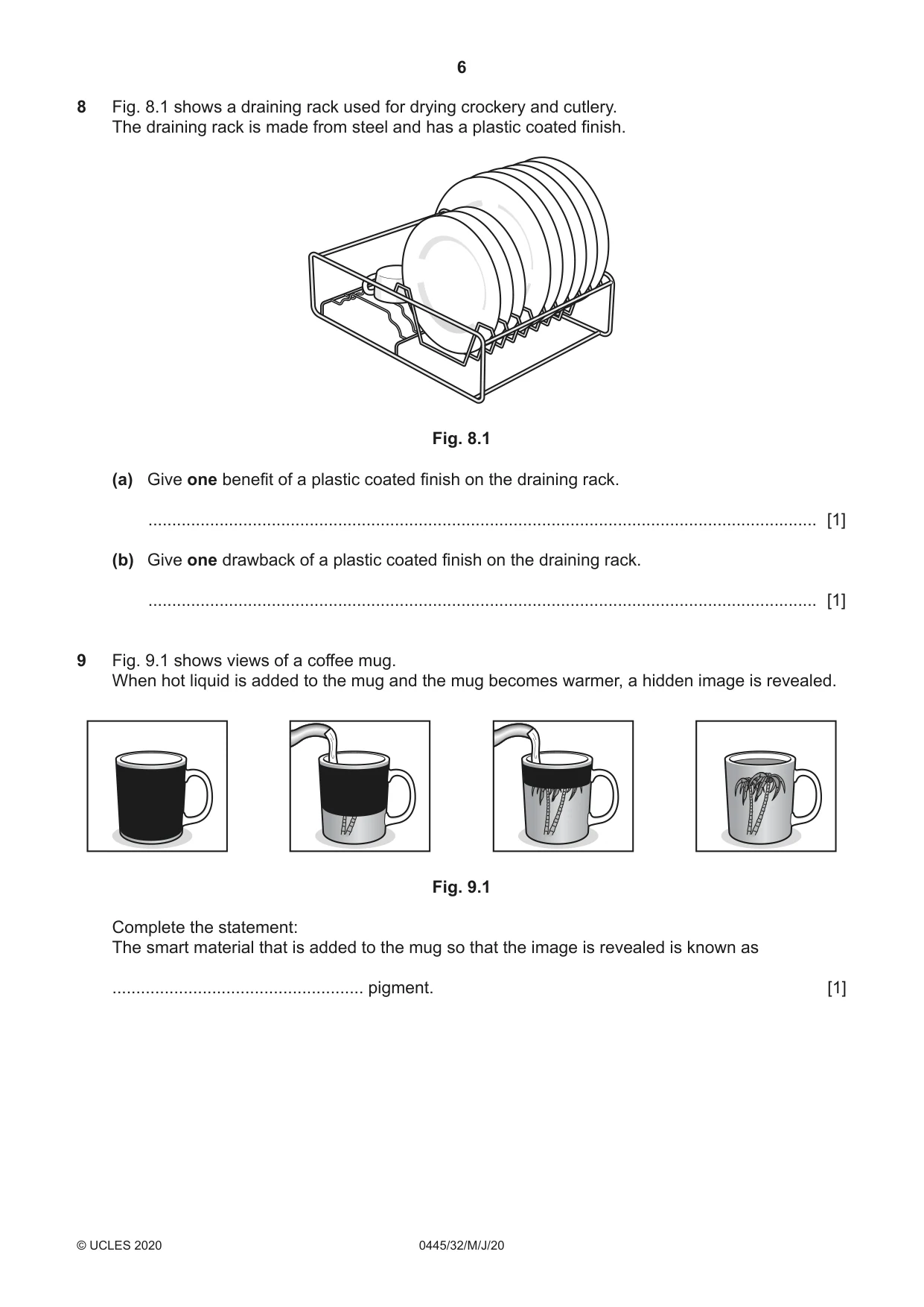
8 Fig. 8.1 shows a draining rack used for drying crockery and cutlery. The draining rack is made from steel and has a plastic coated finish. Fig. 8.1 (a) Give one benefit of a plastic coated finish on the draining rack. ............................................................................................................................................. [1] (b) Give one drawback of a plastic coated finish on the draining rack. ............................................................................................................................................. [1]
Mark scheme: 8(a) Tough, durable, attractive, resists corrosion, evenly applied 1 1 8(b) When cut/chipped can be difficult to repair 1
Q9 · Views of a coffee mug
9 Fig. 9.1 shows views of a coffee mug. When hot liquid is added to the mug and the mug becomes warmer, a hidden image is revealed. Fig. 9.1 Complete the statement: The smart material that is added to the mug so that the image is revealed is known as ..................................................... pigment. [1]
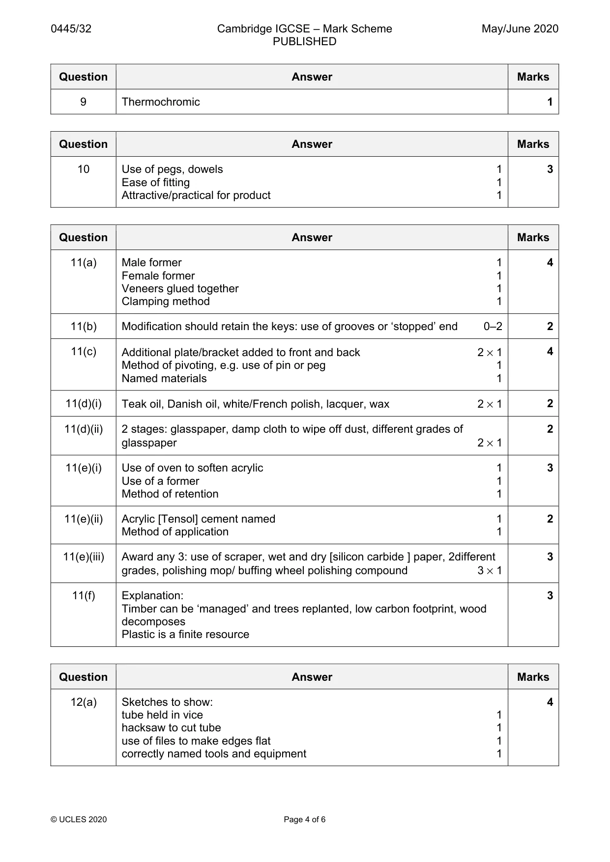
Mark scheme: 9 Thermochromic 1
Q10 · Views of a desk tidy made from 3 mm thick MDF
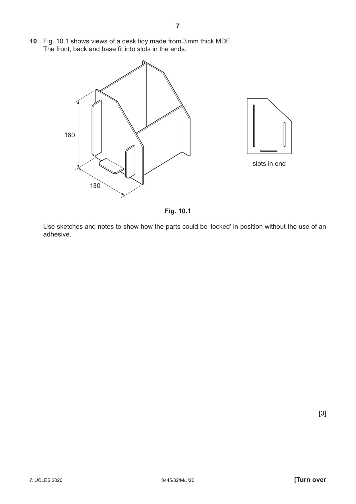
10 Fig. 10.1 shows views of a desk tidy made from 3 mm thick MDF. The front, back and base fit into slots in the ends. 160 slots in end 130 Fig. 10.1 Use sketches and notes to show how the parts could be ‘locked’ in position without the use of an adhesive. [3]
Mark scheme: 10 Use of pegs, dowels 1 3 Ease of fitting 1 Attractive/practical for product 1
Q11 · Views of an incomplete design for a key rack made from hardwood
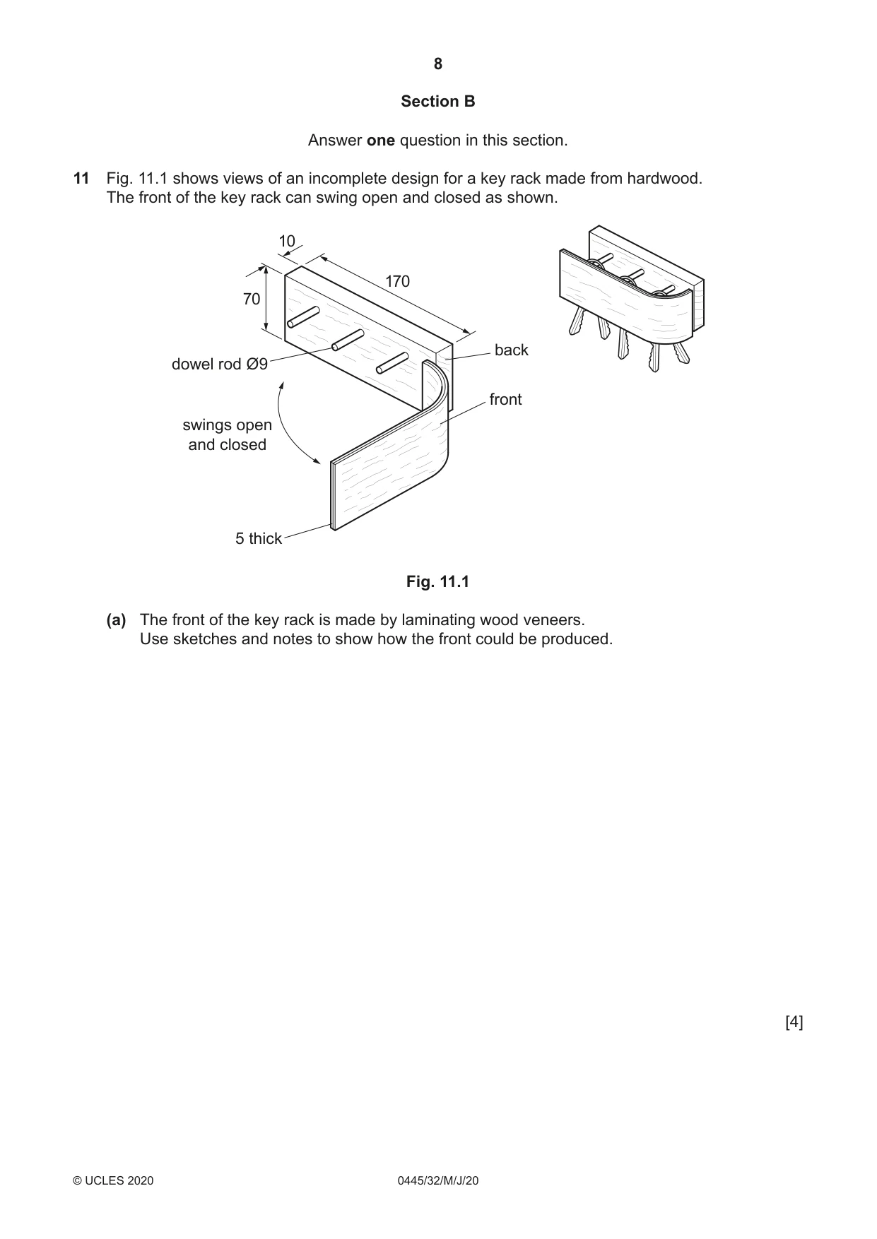
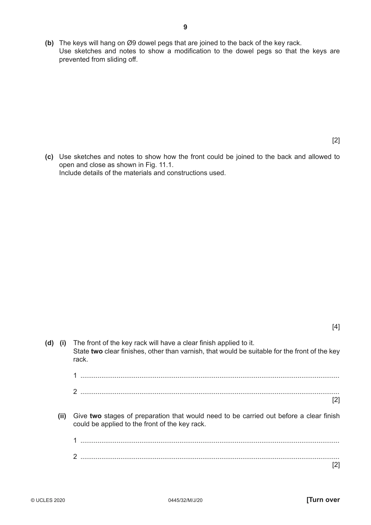
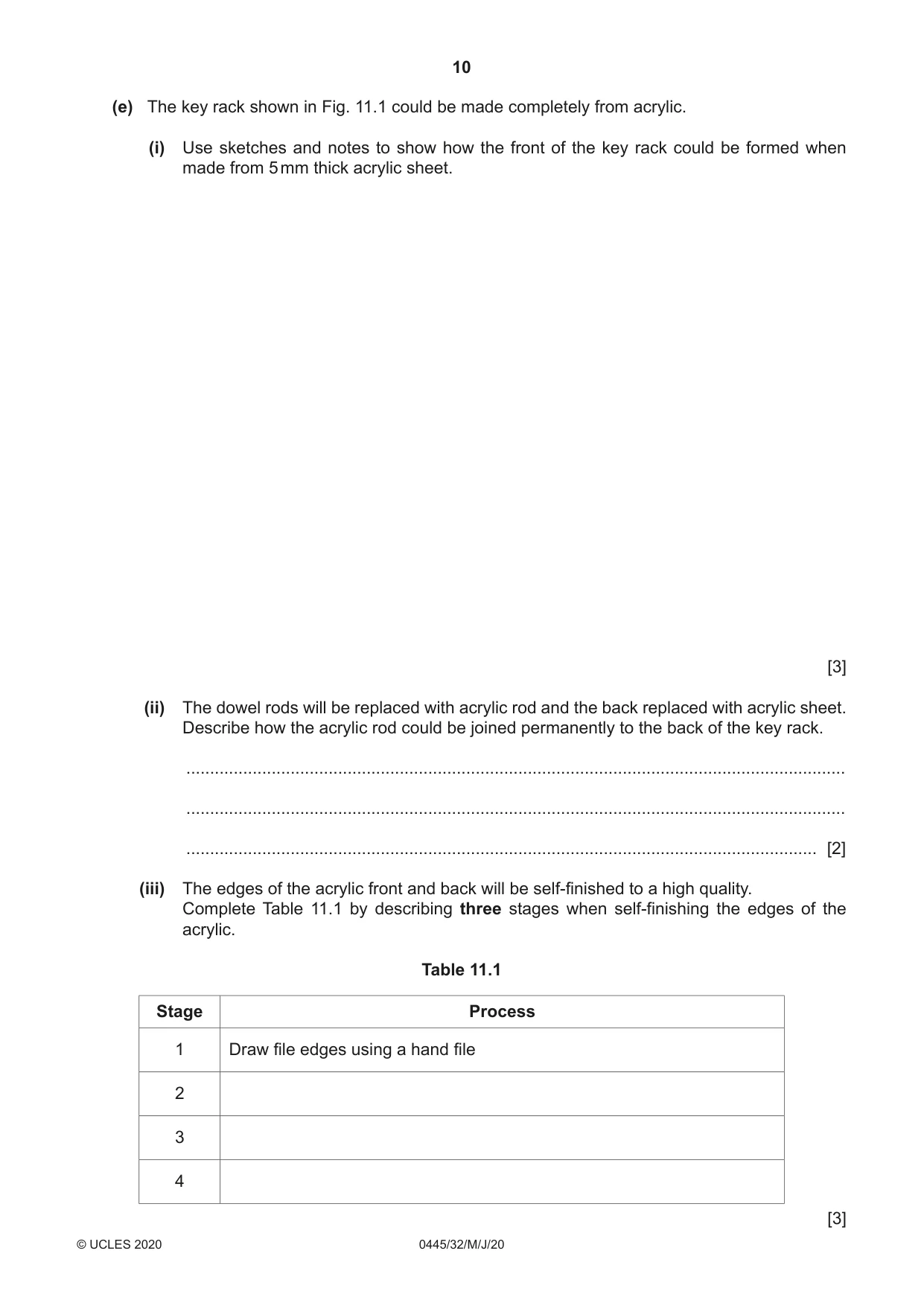
11 Fig. 11.1 shows views of an incomplete design for a key rack made from hardwood. The front of the key rack can swing open and closed as shown. 10 170 70 back dowel rod Ø9 front swings open and closed 5 thick Fig. 11.1 (a) The front of the key rack is made by laminating wood veneers. Use sketches and notes to show how the front could be produced. [4] (b) The keys will hang on Ø9 dowel pegs that are joined to the back of the key rack. Use sketches and notes to show a modification to the dowel pegs so that the keys are prevented from sliding off. [2] (c) Use sketches and notes to show how the front could be joined to the back and allowed to open and close as shown in Fig. 11.1. Include details of the materials and constructions used. [4] (d) (i) The front of the key rack will have a clear finish applied to it. State two clear finishes, other than varnish, that would be suitable for the front of the key rack. 1 ........................................................................................................................................ 2 ........................................................................................................................................ [2] (ii) Give two stages of preparation that would need to be carried out before a clear finish could be applied to the front of the key rack. 1 ........................................................................................................................................ 2 ........................................................................................................................................ [2] (e) The key rack shown in Fig. 11.1 could be made completely from acrylic. (i) Use sketches and notes to show how the front of the key rack could be formed when made from 5 mm thick acrylic sheet. [3] (ii) The dowel rods will be replaced with acrylic rod and the back replaced with acrylic sheet. Describe how the acrylic rod could be joined permanently to the back of the key rack. ........................................................................................................................................... ........................................................................................................................................... ..................................................................................................................................... [2] (iii) The edges of the acrylic front and back will be self-finished to a high quality. Complete Table 11.1 by describing three stages when self-finishing the edges of the acrylic. Table 11.1 Stage Process 1 Draw file edges using a hand file 2 3 4 [3] (f) When designing products, designers should select materials that are sustainable. The key rack could be made from wood or plastic. Explain why wood is considered to be more sustainable than plastic. ................................................................................................................................................... ................................................................................................................................................... ................................................................................................................................................... ............................................................................................................................................. [3]
Mark scheme: 11(a) Male former 1 4 Female former 1 Veneers glued together 1 Clamping method 1 11(b) Modification should retain the keys: use of grooves or ‘stopped’ end 0–2 2 11(c) Additional plate/bracket added to front and back 2 × 1 4 Method of pivoting, e.g. use of pin or peg 1 Named materials 1 11(d)(i) Teak oil, Danish oil, white/French polish, lacquer, wax 2 × 1 2 11(d)(ii) 2 stages: glasspaper, damp cloth to wipe off dust, different grades of 2 glasspaper 2 × 1 11(e)(i) Use of oven to soften acrylic 1 3 Use of a former 1 Method of retention 1 11(e)(ii) Acrylic [Tensol] cement named 1 2 Method of application 1 11(e)(iii) Award any 3: use of scraper, wet and dry [silicon carbide ] paper, 2different 3 grades, polishing mop/ buffing wheel polishing compound 3 × 1 11(f) Explanation: 3 Timber can be ‘managed’ and trees replanted, low carbon footprint, wood decomposes Plastic is a finite resource
Q12 · An incomplete design for a rack to store items of equipment used for cycle maintenance
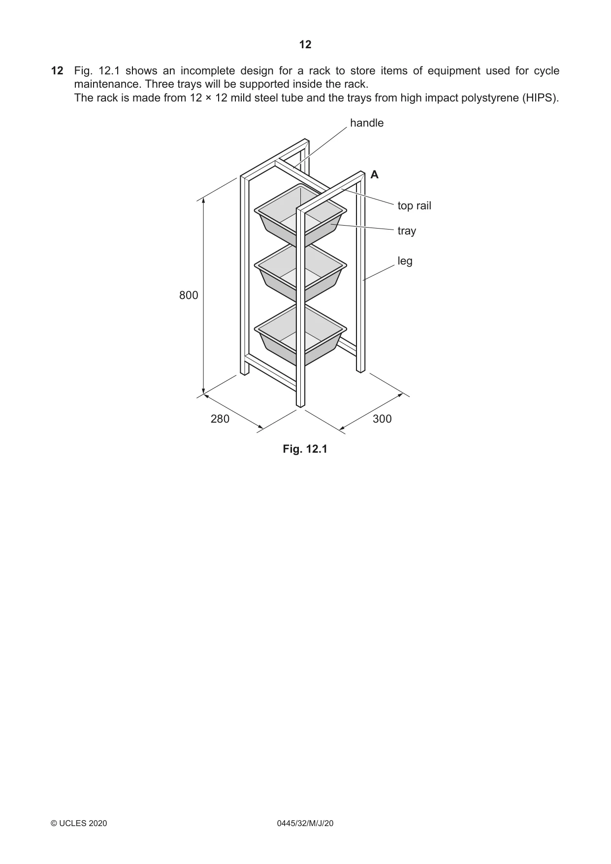
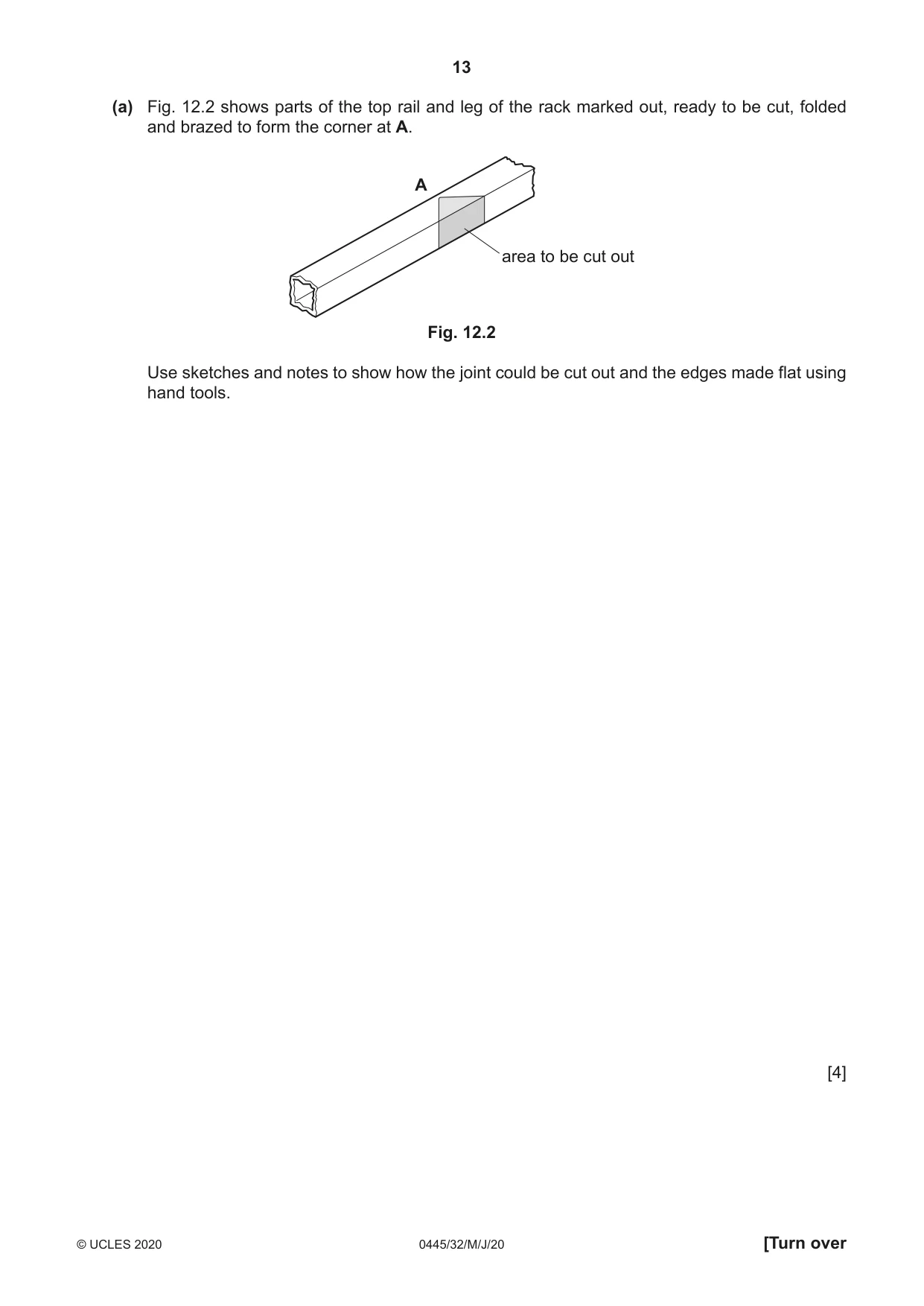
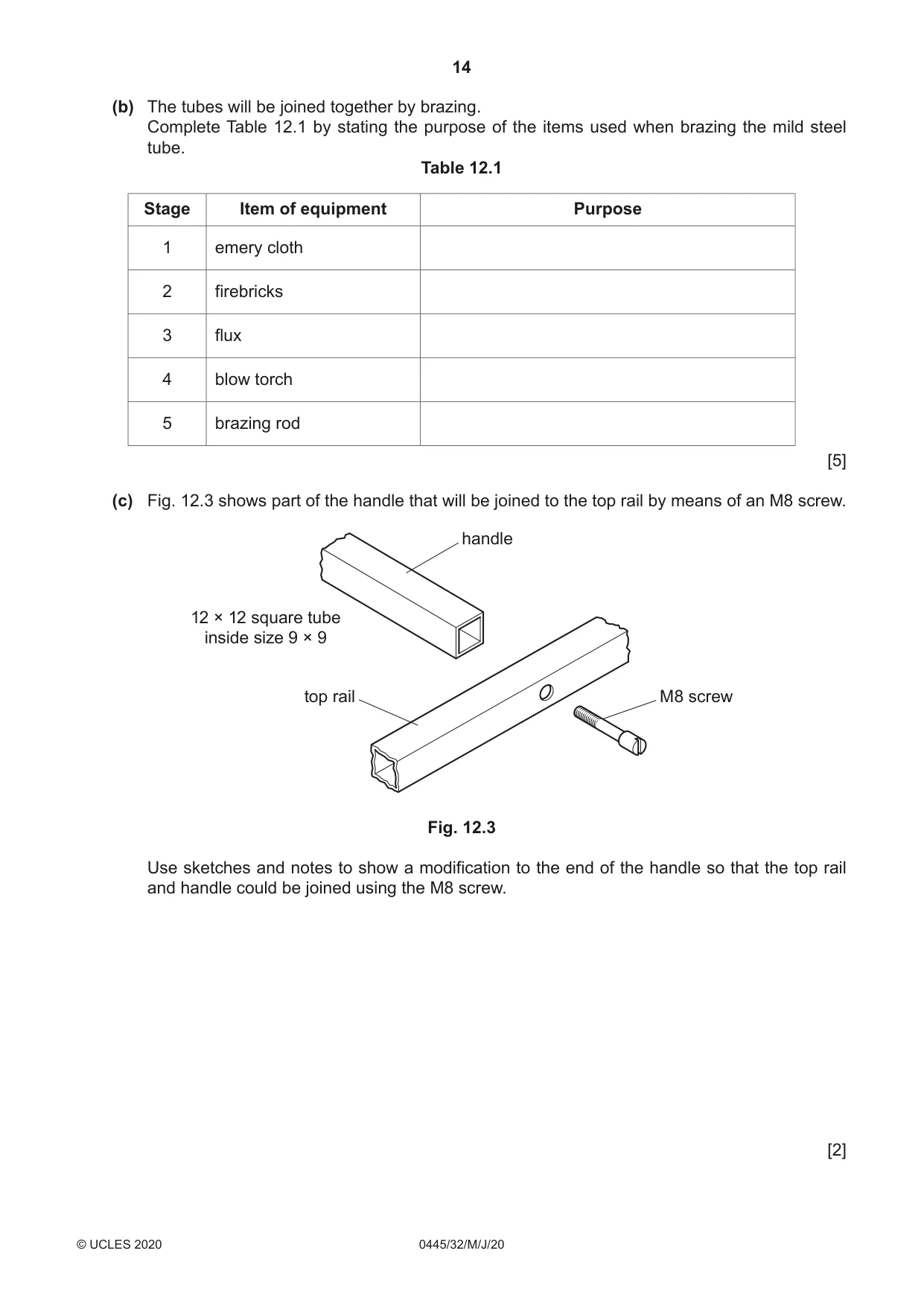
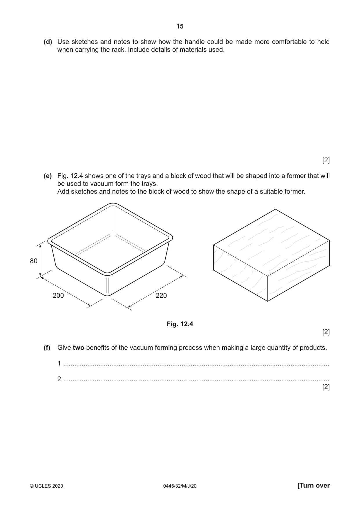
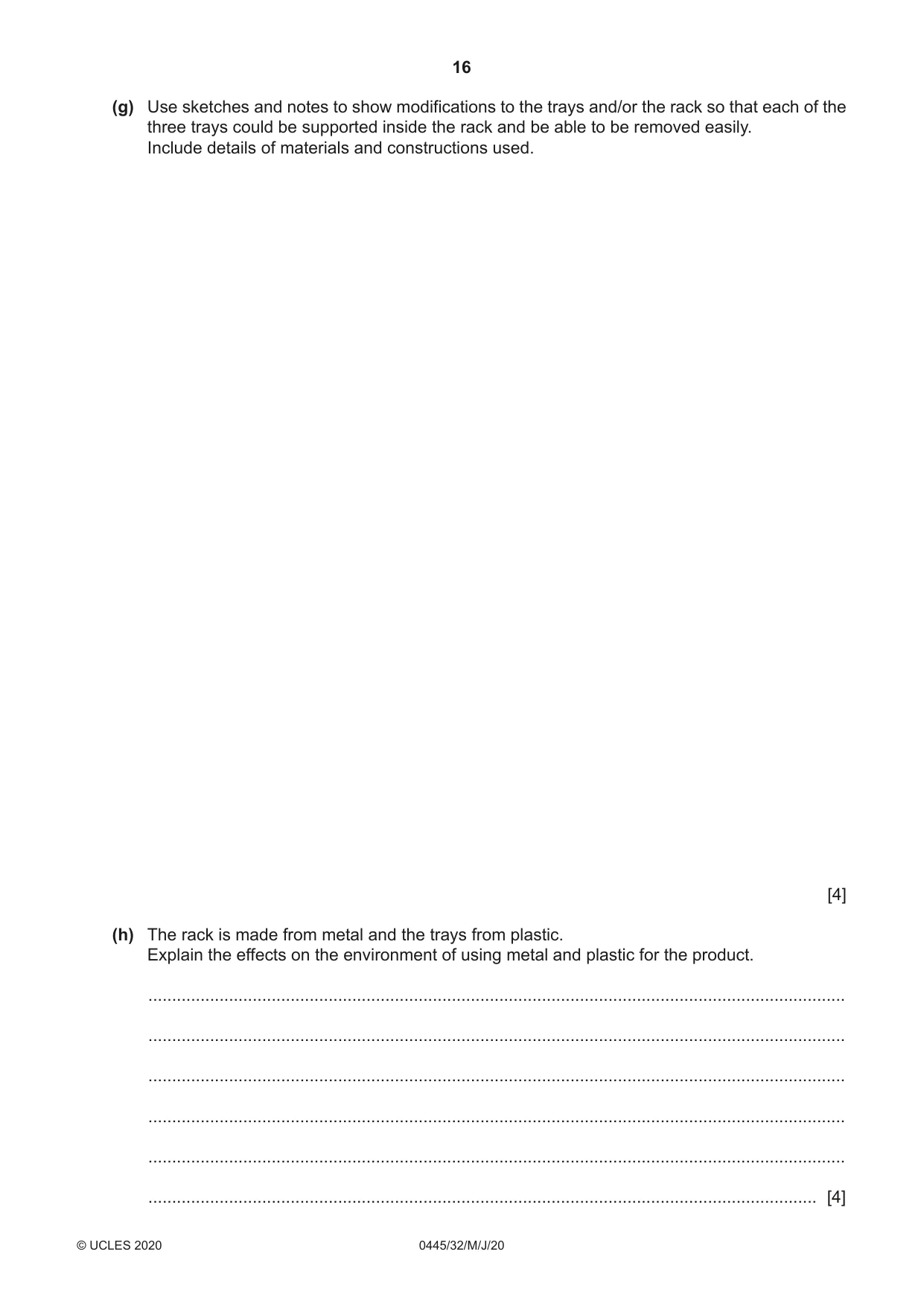
12 Fig. 12.1 shows an incomplete design for a rack to store items of equipment used for cycle maintenance. Three trays will be supported inside the rack. The rack is made from 12 × 12 mild steel tube and the trays from high impact polystyrene (HIPS). handle A top rail tray leg 800 280 300 Fig. 12.1 (a) Fig. 12.2 shows parts of the top rail and leg of the rack marked out, ready to be cut, folded and brazed to form the corner at A. A area to be cut out Fig. 12.2 Use sketches and notes to show how the joint could be cut out and the edges made flat using hand tools. [4] (b) The tubes will be joined together by brazing. Complete Table 12.1 by stating the purpose of the items used when brazing the mild steel tube. Table 12.1 Stage Item of equipment Purpose 1 emery cloth 2 firebricks 3 flux 4 blow torch 5 brazing rod [5] (c) Fig. 12.3 shows part of the handle that will be joined to the top rail by means of an M8 screw. handle 12 × 12 square tube inside size 9 × 9 top rail M8 screw Fig. 12.3 Use sketches and notes to show a modification to the end of the handle so that the top rail and handle could be joined using the M8 screw. [2] (d) Use sketches and notes to show how the handle could be made more comfortable to hold when carrying the rack. Include details of materials used. [2] (e) Fig. 12.4 shows one of the trays and a block of wood that will be shaped into a former that will be used to vacuum form the trays. Add sketches and notes to the block of wood to show the shape of a suitable former. 80 200 220 Fig. 12.4 [2] (f) Give two benefits of the vacuum forming process when making a large quantity of products. 1 ................................................................................................................................................ 2 ................................................................................................................................................ [2] (g) Use sketches and notes to show modifications to the trays and/or the rack so that each of the three trays could be supported inside the rack and be able to be removed easily. Include details of materials and constructions used. [4] (h) The rack is made from metal and the trays from plastic. Explain the effects on the environment of using metal and plastic for the product. ................................................................................................................................................... ................................................................................................................................................... ................................................................................................................................................... ................................................................................................................................................... ................................................................................................................................................... ............................................................................................................................................. [4]
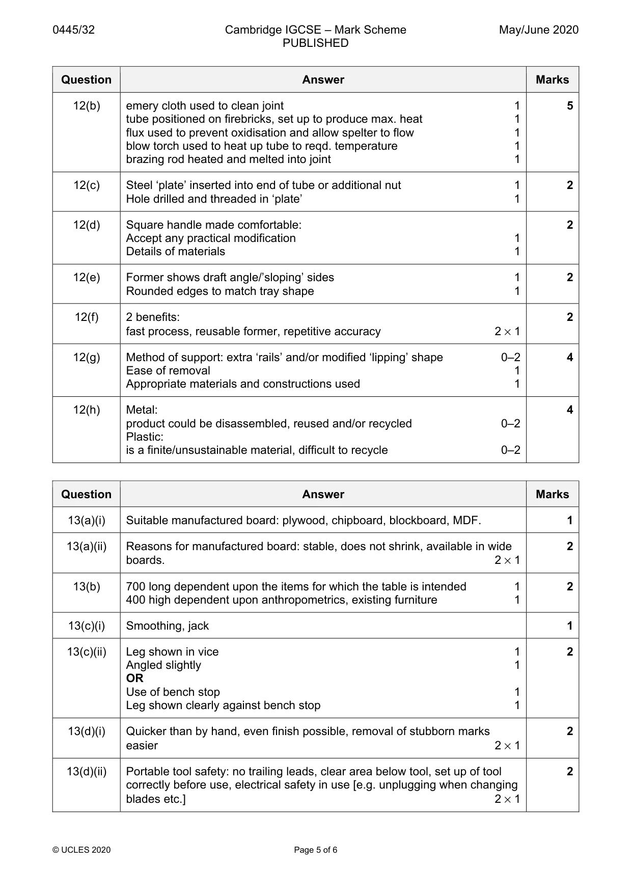
Mark scheme: 12(a) Sketches to show: 4 tube held in vice 1 hacksaw to cut tube 1 use of files to make edges flat 1 correctly named tools and equipment 1 12(b) emery cloth used to clean joint 1 5 tube positioned on firebricks, set up to produce max. heat 1 flux used to prevent oxidisation and allow spelter to flow 1 blow torch used to heat up tube to reqd. temperature 1 brazing rod heated and melted into joint 1 12(c) Steel ‘plate’ inserted into end of tube or additional nut 1 2 Hole drilled and threaded in ‘plate’ 1 12(d) Square handle made comfortable: 2 Accept any practical modification 1 Details of materials 1 12(e) Former shows draft angle/’sloping’ sides 1 2 Rounded edges to match tray shape 1 12(f) 2 benefits: 2 fast process, reusable former, repetitive accuracy 2 × 1 12(g) Method of support: extra ‘rails’ and/or modified ‘lipping’ shape 0–2 4 Ease of removal 1 Appropriate materials and constructions used 1 12(h) Metal: 4 product could be disassembled, reused and/or recycled 0–2 Plastic: is a finite/unsustainable material, difficult to recycle 0–2
Q13 · A small table to be made in a school workshop
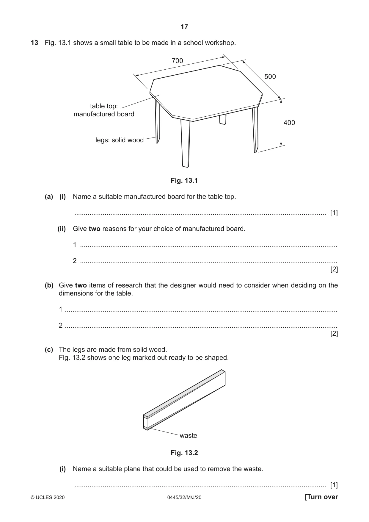
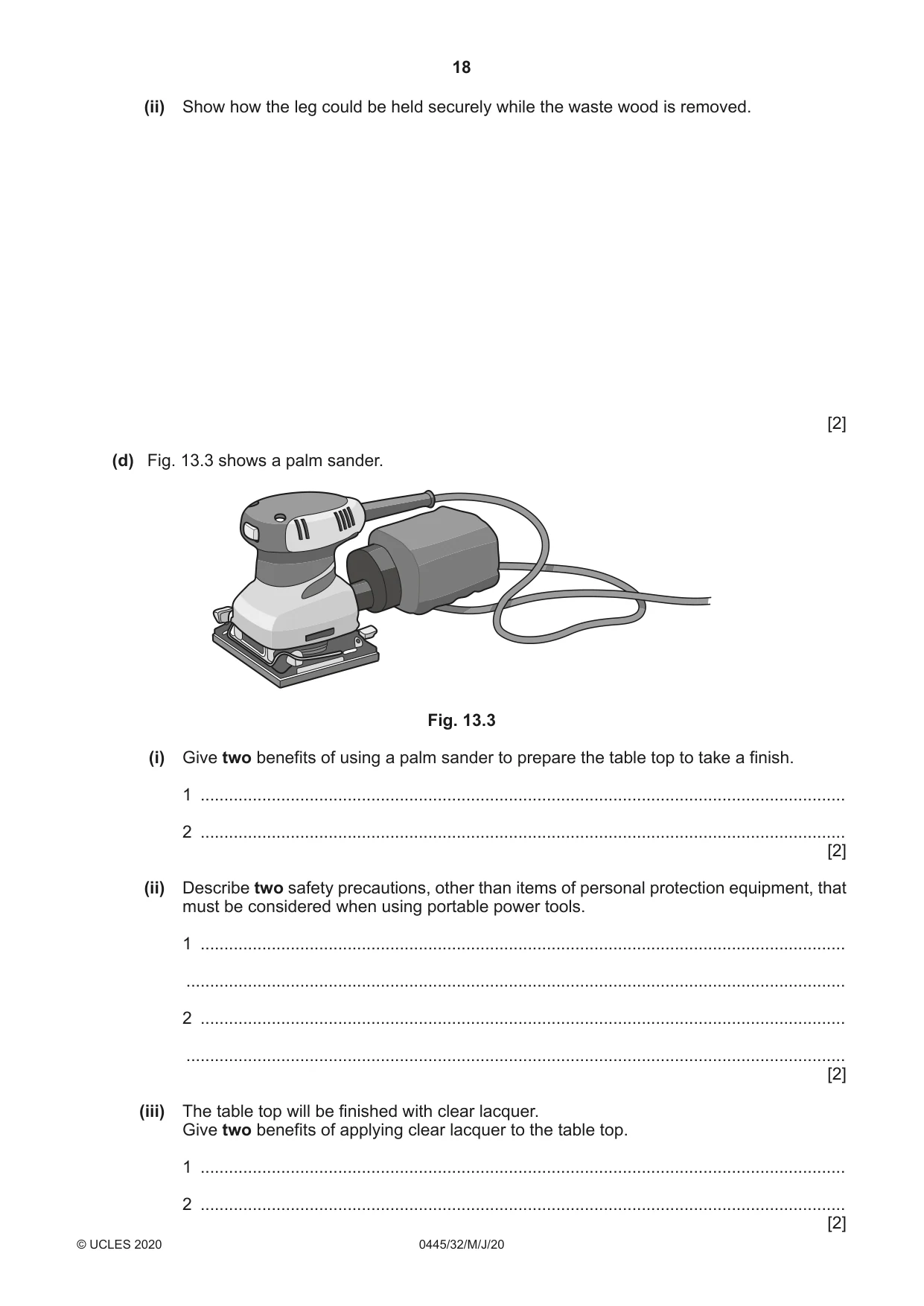
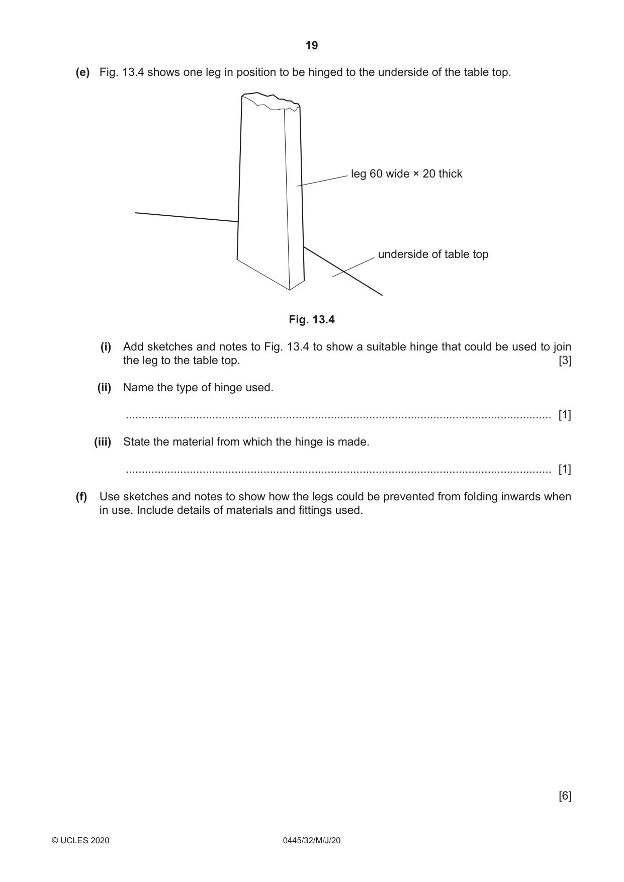
13 Fig. 13.1 shows a small table to be made in a school workshop. 700 500 table top: manufactured board 400 legs: solid wood Fig. 13.1 (a) (i) Name a suitable manufactured board for the table top. ..................................................................................................................................... [1] (ii) Give two reasons for your choice of manufactured board. 1 ........................................................................................................................................ 2 ........................................................................................................................................ [2] (b) Give two items of research that the designer would need to consider when deciding on the dimensions for the table. 1 ................................................................................................................................................ 2 ................................................................................................................................................ [2] (c) The legs are made from solid wood. Fig. 13.2 shows one leg marked out ready to be shaped. waste Fig. 13.2 (i) Name a suitable plane that could be used to remove the waste. ..................................................................................................................................... [1] (ii) Show how the leg could be held securely while the waste wood is removed. [2] (d) Fig. 13.3 shows a palm sander. Fig. 13.3 (i) Give two benefits of using a palm sander to prepare the table top to take a finish. 1 ........................................................................................................................................ 2 ........................................................................................................................................ [2] (ii) Describe two safety precautions, other than items of personal protection equipment, that must be considered when using portable power tools. 1 ........................................................................................................................................ ........................................................................................................................................... 2 ........................................................................................................................................ ........................................................................................................................................... [2] (iii) The table top will be finished with clear lacquer. Give two benefits of applying clear lacquer to the table top. 1 ........................................................................................................................................ 2 ........................................................................................................................................ [2] (e) Fig. 13.4 shows one leg in position to be hinged to the underside of the table top. leg 60 wide × 20 thick underside of table top Fig. 13.4 (i) Add sketches and notes to Fig. 13.4 to show a suitable hinge that could be used to join the leg to the table top. [3] (ii) Name the type of hinge used. ..................................................................................................................................... [1] (iii) State the material from which the hinge is made. ..................................................................................................................................... [1] (f) Use sketches and notes to show how the legs could be prevented from folding inwards when in use. Include details of materials and fittings used. [6]
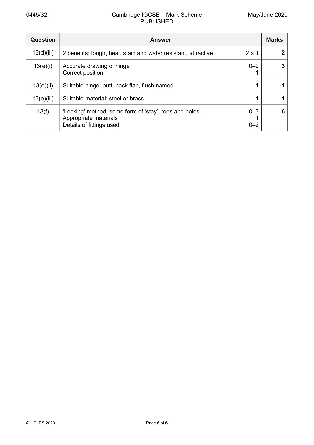
Mark scheme: 13(a)(i) Suitable manufactured board: plywood, chipboard, blockboard, MDF. 1 13(a)(ii) Reasons for manufactured board: stable, does not shrink, available in wide 2 boards. 2 × 1 13(b) 700 long dependent upon the items for which the table is intended 1 2 400 high dependent upon anthropometrics, existing furniture 1 13(c)(i) Smoothing, jack 1 13(c)(ii) Leg shown in vice 1 2 Angled slightly 1 OR Use of bench stop 1 Leg shown clearly against bench stop 1 13(d)(i) Quicker than by hand, even finish possible, removal of stubborn marks 2 easier 2 × 1 13(d)(ii) Portable tool safety: no trailing leads, clear area below tool, set up of tool 2 correctly before use, electrical safety in use [e.g. unplugging when changing blades etc.] 2 × 1 13(d)(iii) 2 benefits: tough, heat, stain and water resistant, attractive 2 × 1 2 13(e)(i) Accurate drawing of hinge 0–2 3 Correct position 1 13(e)(ii) Suitable hinge: butt, back flap, flush named 1 1 13(e)(iii) Suitable material: steel or brass 1 1 13(f) ‘Locking’ method: some form of ‘stay’, rods and holes. 0–3 6 Appropriate materials 1 Details of fittings used 0–2
What was in this paper
The subtopics covered by these 13 questions, and how many questions each got. Open one in a new tab to see every Cambridge question on it.