Cambridge IGCSE Design and Technology 0445 — 2020 May/June Paper 3 · Variant 1
0445/31/M/J/20 · 13 questions · 96 marks · ≈108 min
The question paper and its mark scheme, free to read here and free to download. This is Cambridge’s own paper, exactly as it was sat.
Question paper20 pages

Mark scheme6 pages
Answers below. Sit the paper first if you are practising.
Questions as text
Q1 · Give two pieces of information required when buying woodscrews
1 Give two pieces of information required when buying woodscrews. 1 ....................................................................................................................................................... 2 ....................................................................................................................................................... [2]
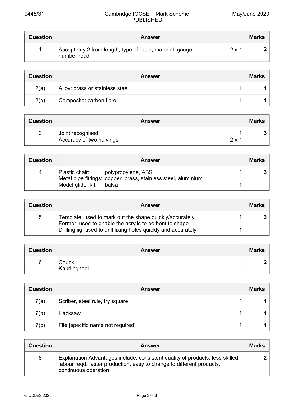
Mark scheme: Question Answer Marks 1 Accept any 2 from length, type of head, material, gauge, 2 × 1 2 number reqd.
Q2 · A list of materials is given below
2 A list of materials is given below. brass CFRP copper polycarbonate stainless steel Select from the list one material that is: (a) an alloy ............................................................................................................................... [1] (b) a composite ........................................................................................................................ [1]
Mark scheme: 2(a) Alloy: brass or stainless steel 1 1 2(b) Composite: carbon fibre 1 1
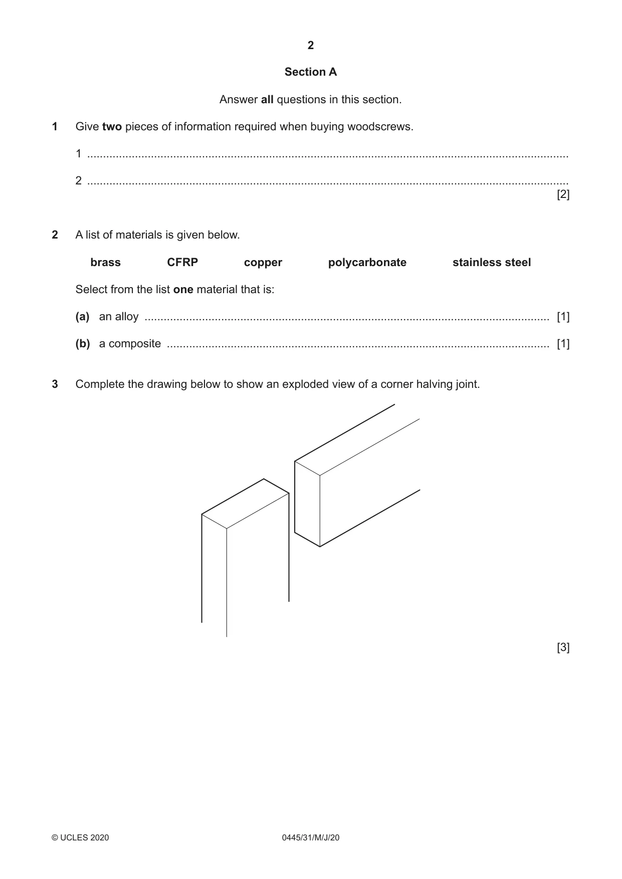
Q3 · Complete the drawing below to show an exploded view of a corner halving joint
3 Complete the drawing below to show an exploded view of a corner halving joint. [3]
Mark scheme: 3 Joint recognised 1 3 Accuracy of two halvings 2 × 1
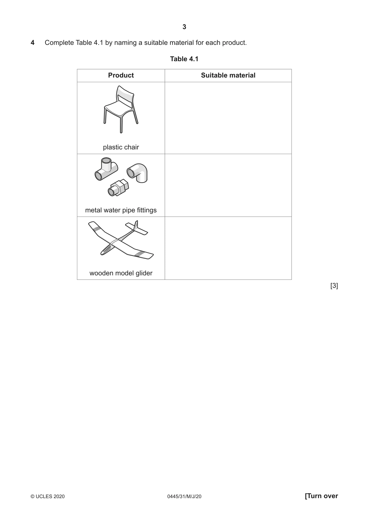
Q4 · Complete Table 4.1 by naming a suitable material for each product
4 Complete Table 4.1 by naming a suitable material for each product. Table 4.1 Product Suitable material plastic chair metal water pipe fittings wooden model glider [3]
Mark scheme: 4 Plastic chair: polypropylene, ABS 1 3 Metal pipe fittings: copper, brass, stainless steel, aluminium 1 Model glider kit: balsa 1
Q5 · A coat hook for a child
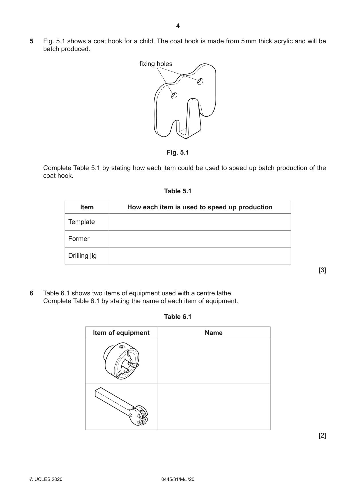
5 Fig. 5.1 shows a coat hook for a child. The coat hook is made from 5 mm thick acrylic and will be batch produced. fixing holes Fig. 5.1 Complete Table 5.1 by stating how each item could be used to speed up batch production of the coat hook. Table 5.1 Item How each item is used to speed up production Template Former Drilling jig [3]
Mark scheme: 5 Template: used to mark out the shape quickly/accurately 1 3 Former: used to enable the acrylic to be bent to shape 1 Drilling jig: used to drill fixing holes quickly and accurately 1
Q6 · Two items of equipment used with a centre lathe
6 Table 6.1 shows two items of equipment used with a centre lathe. Complete Table 6.1 by stating the name of each item of equipment. Table 6.1 Item of equipment Name [2]
Mark scheme: 6 Chuck 1 2 Knurling tool 1
Q7 · The end of a mild steel strip marked out, ready to be shaped
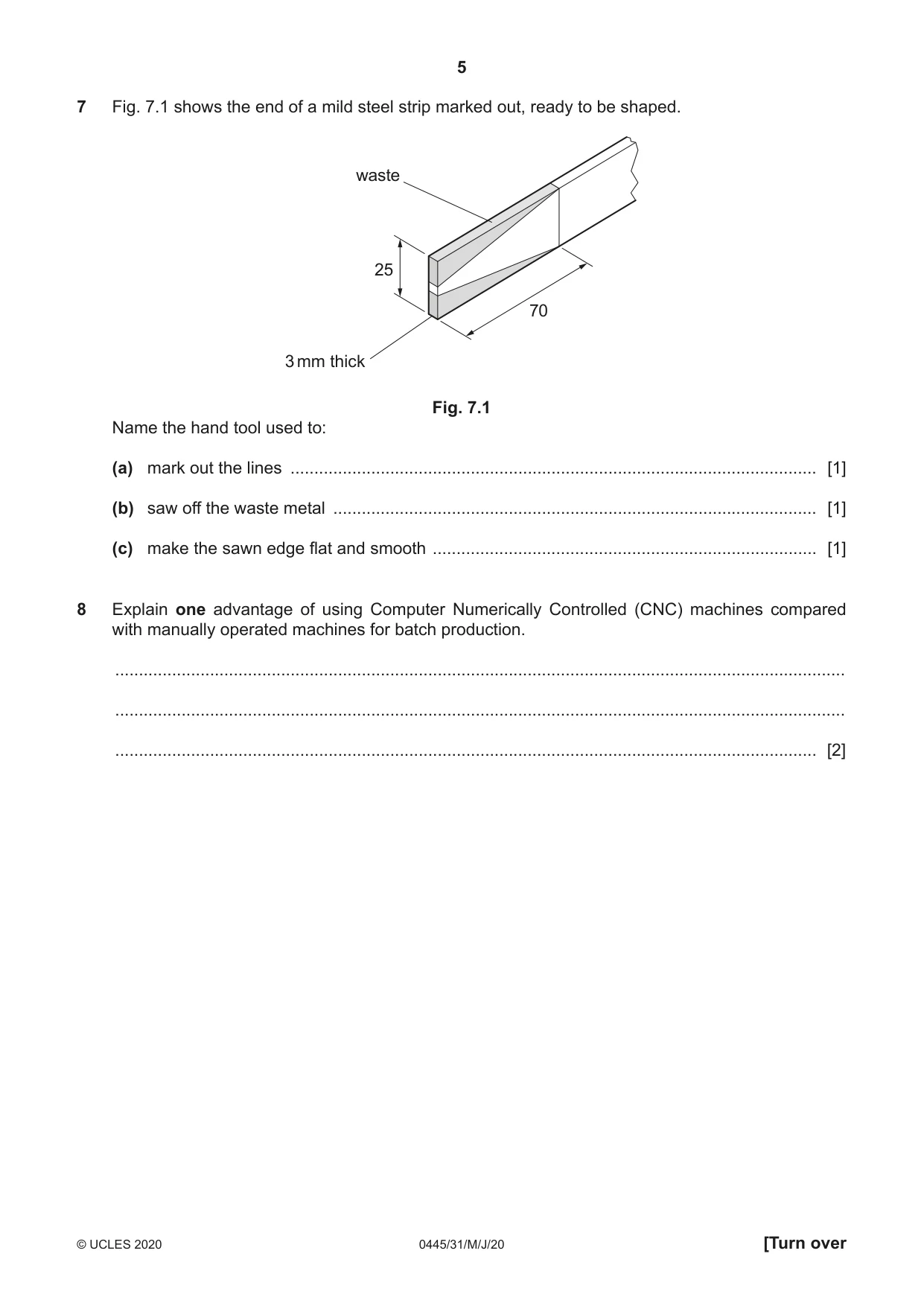
7 Fig. 7.1 shows the end of a mild steel strip marked out, ready to be shaped. waste 25 70 3 mm thick Fig. 7.1 Name the hand tool used to: (a) mark out the lines ............................................................................................................... [1] (b) saw off the waste metal ...................................................................................................... [1] (c) make the sawn edge flat and smooth ................................................................................. [1]
Mark scheme: 7(a) Scriber, steel rule, try square 1 1 7(b) Hacksaw 1 1 7(c) File [specific name not required] 1 1
Q8 · Explain one advantage of using Computer Numerically Controlled (CNC) machines compared…
8 Explain one advantage of using Computer Numerically Controlled (CNC) machines compared with manually operated machines for batch production. .......................................................................................................................................................... .......................................................................................................................................................... .................................................................................................................................................... [2]
Mark scheme: 8 Explanation Advantages include: consistent quality of products, less skilled 2 labour reqd. faster production, easy to change to different products, continuous operation
Q9 · A box made from softwood
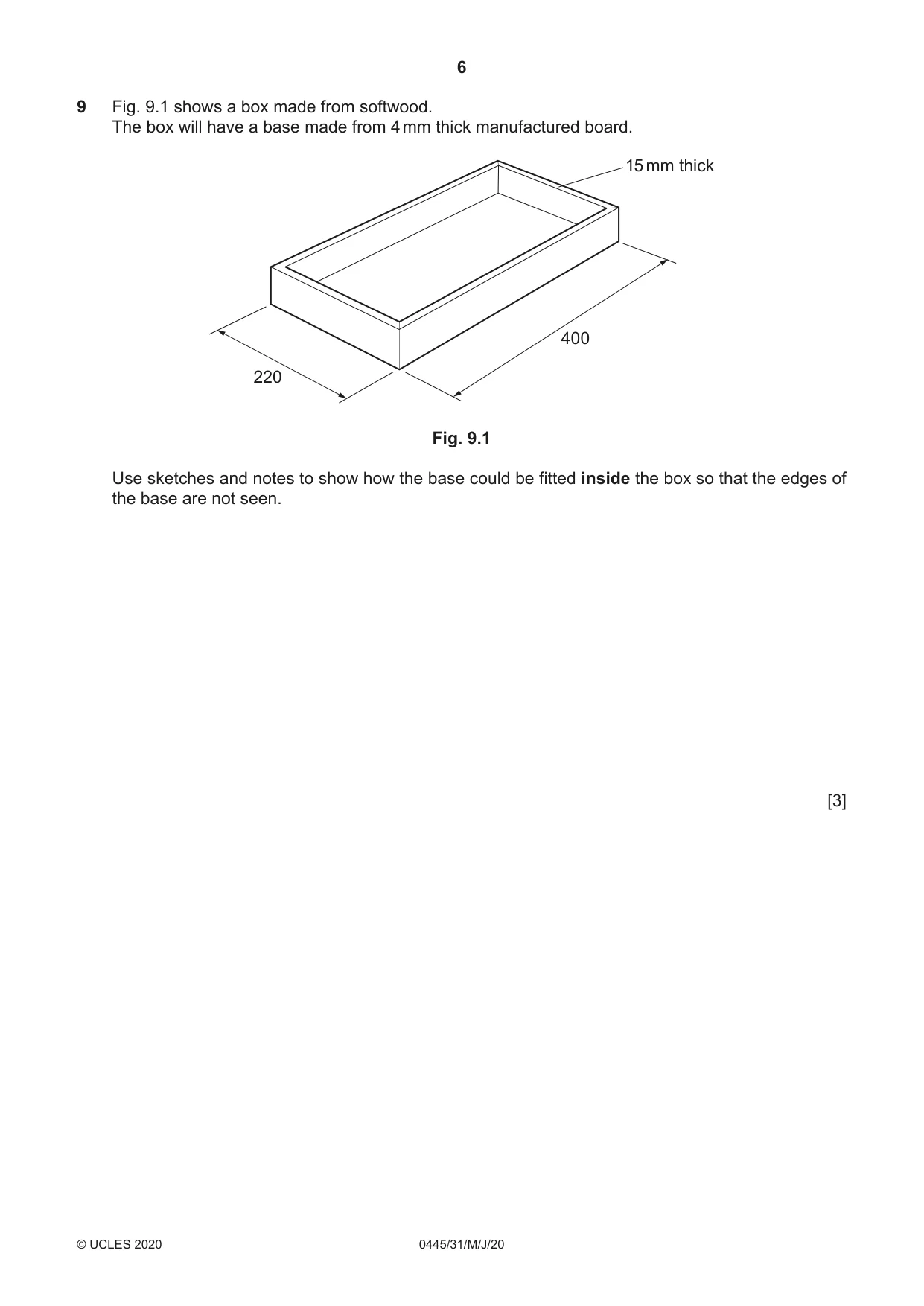
9 Fig. 9.1 shows a box made from softwood. The box will have a base made from 4 mm thick manufactured board. 15 mm thick 400 220 Fig. 9.1 Use sketches and notes to show how the base could be fitted inside the box so that the edges of the base are not seen. [3]
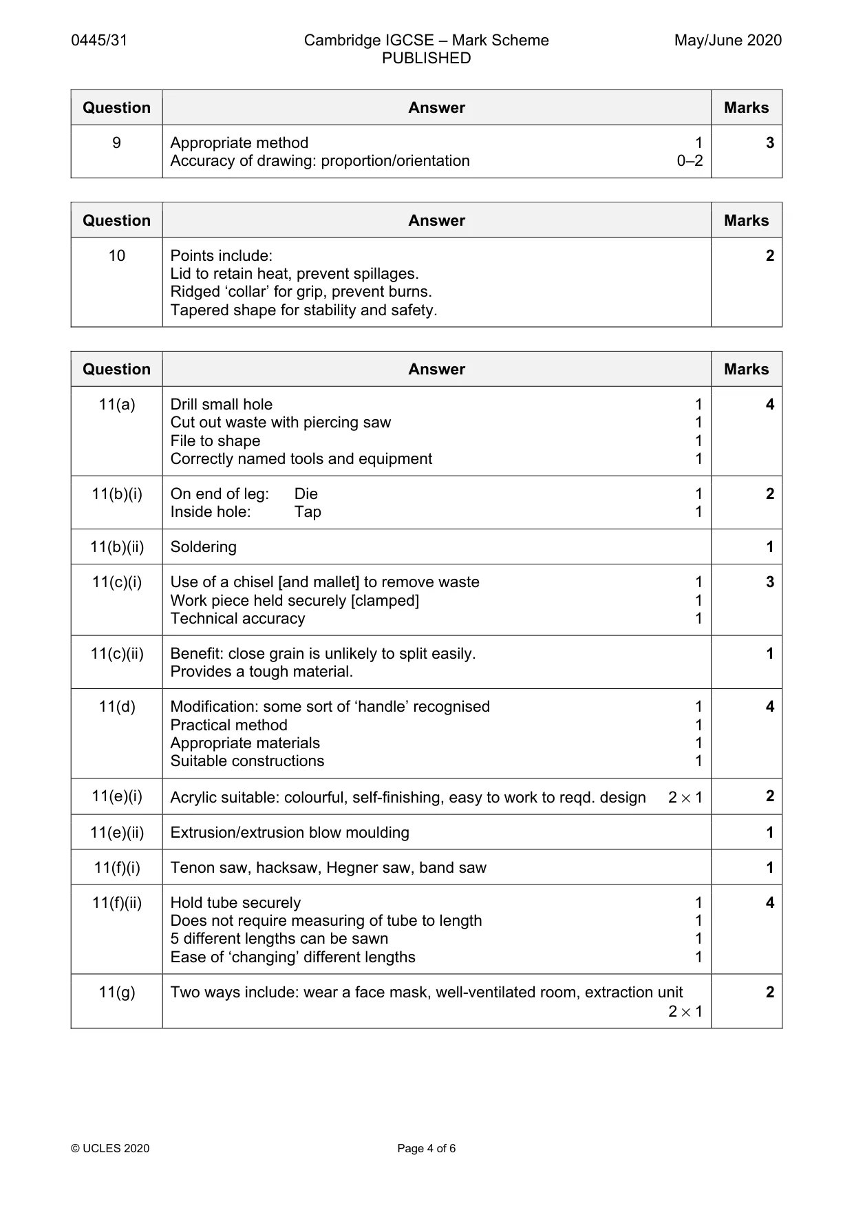
Mark scheme: 9 Appropriate method 1 3 Accuracy of drawing: proportion/orientation 0–2
Q10 · A plastic cup used for hot drinks
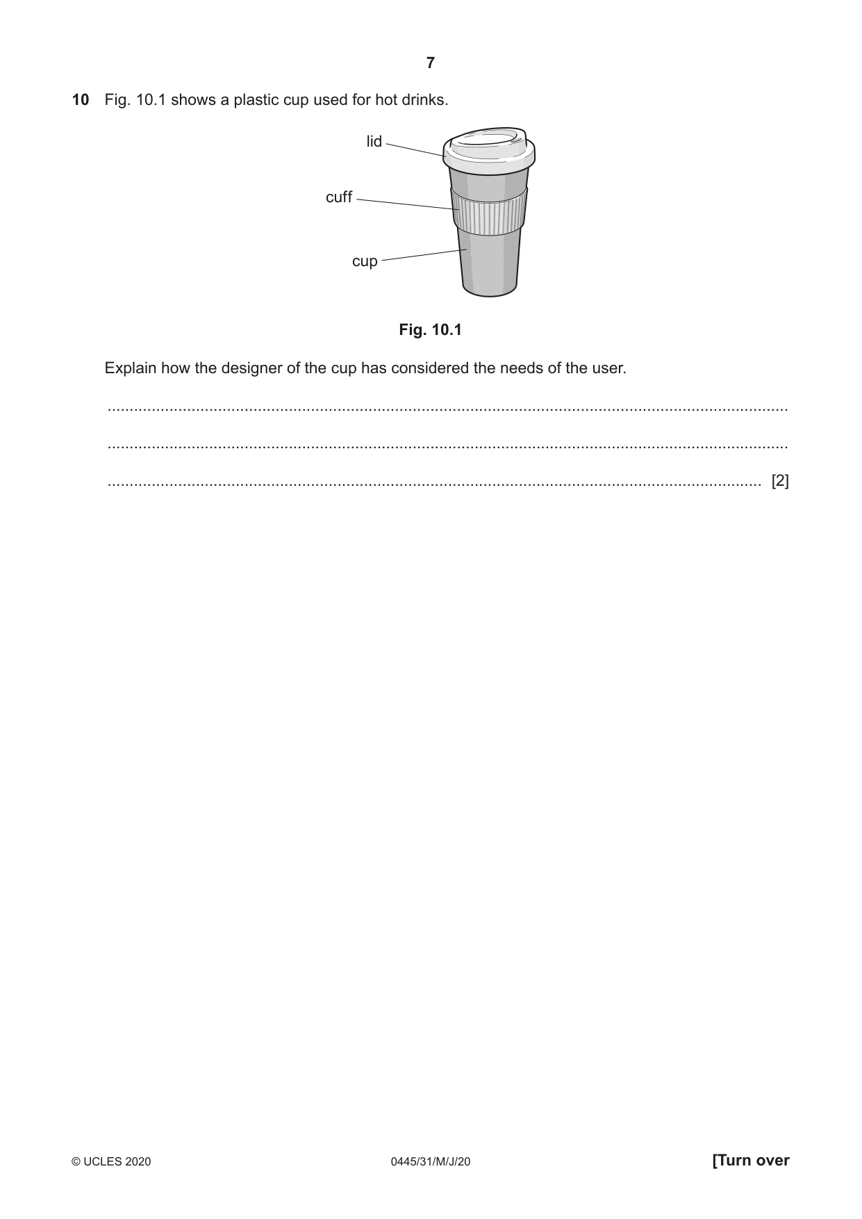
10 Fig. 10.1 shows a plastic cup used for hot drinks. lid cuff cup Fig. 10.1 Explain how the designer of the cup has considered the needs of the user. .......................................................................................................................................................... .......................................................................................................................................................... .................................................................................................................................................... [2]
Mark scheme: 10 Points include: 2 Lid to retain heat, prevent spillages. Ridged ‘collar’ for grip, prevent burns. Tapered shape for stability and safety.
Q11 · A pen and pencil holder
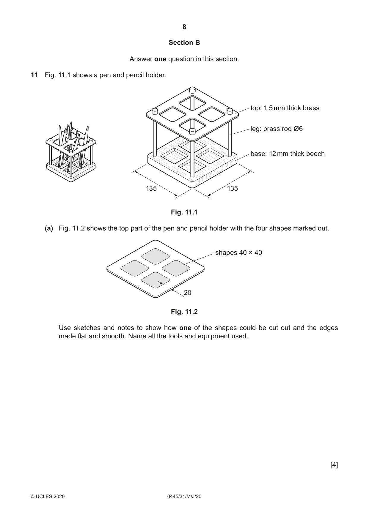
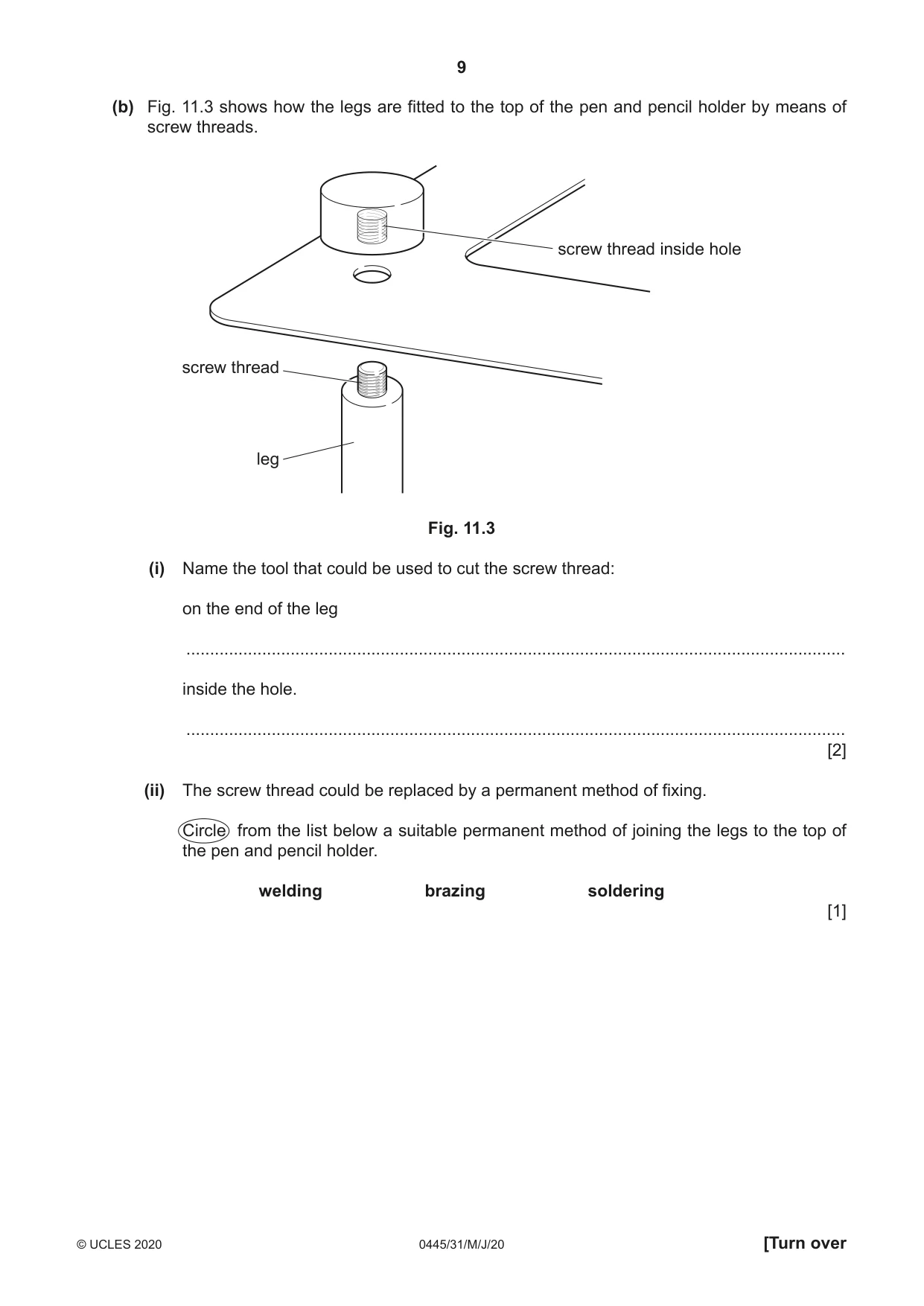
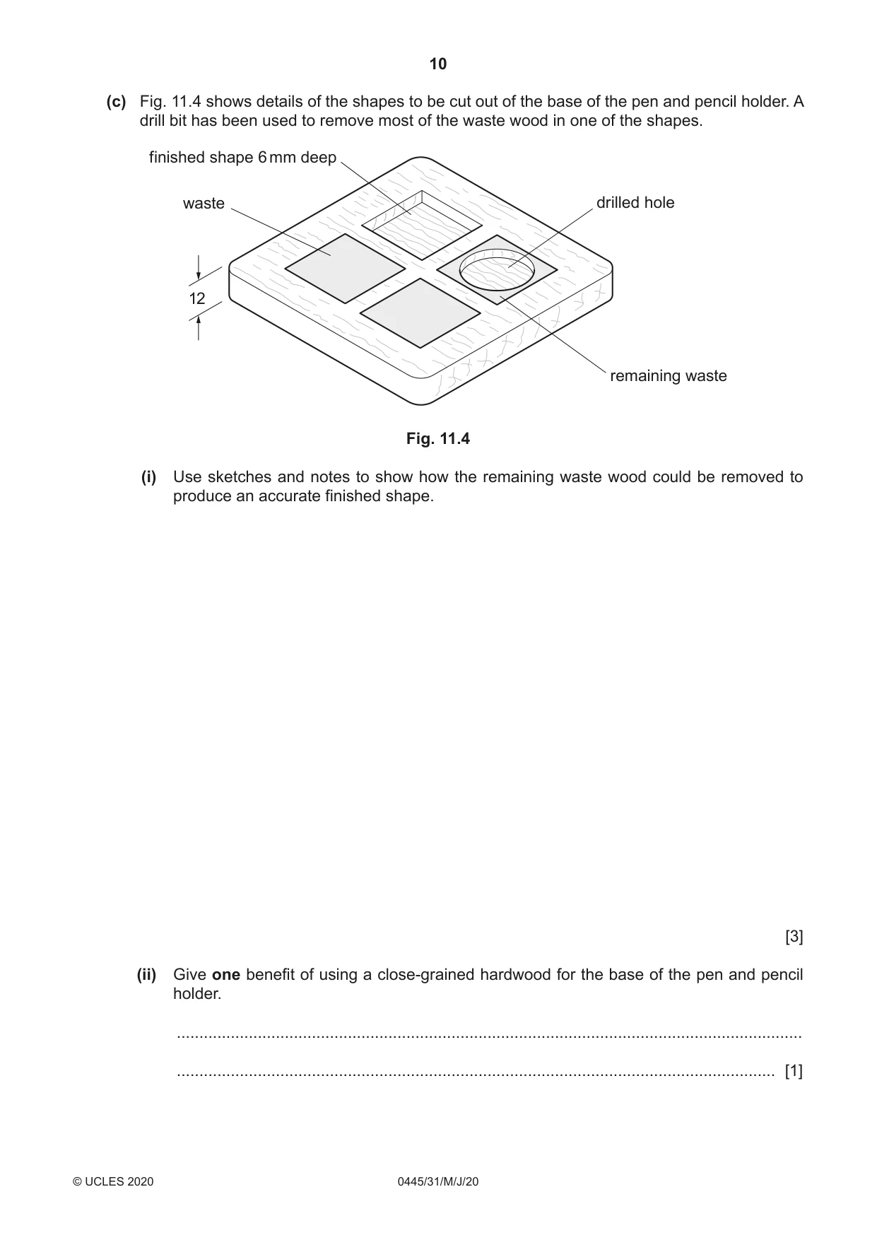
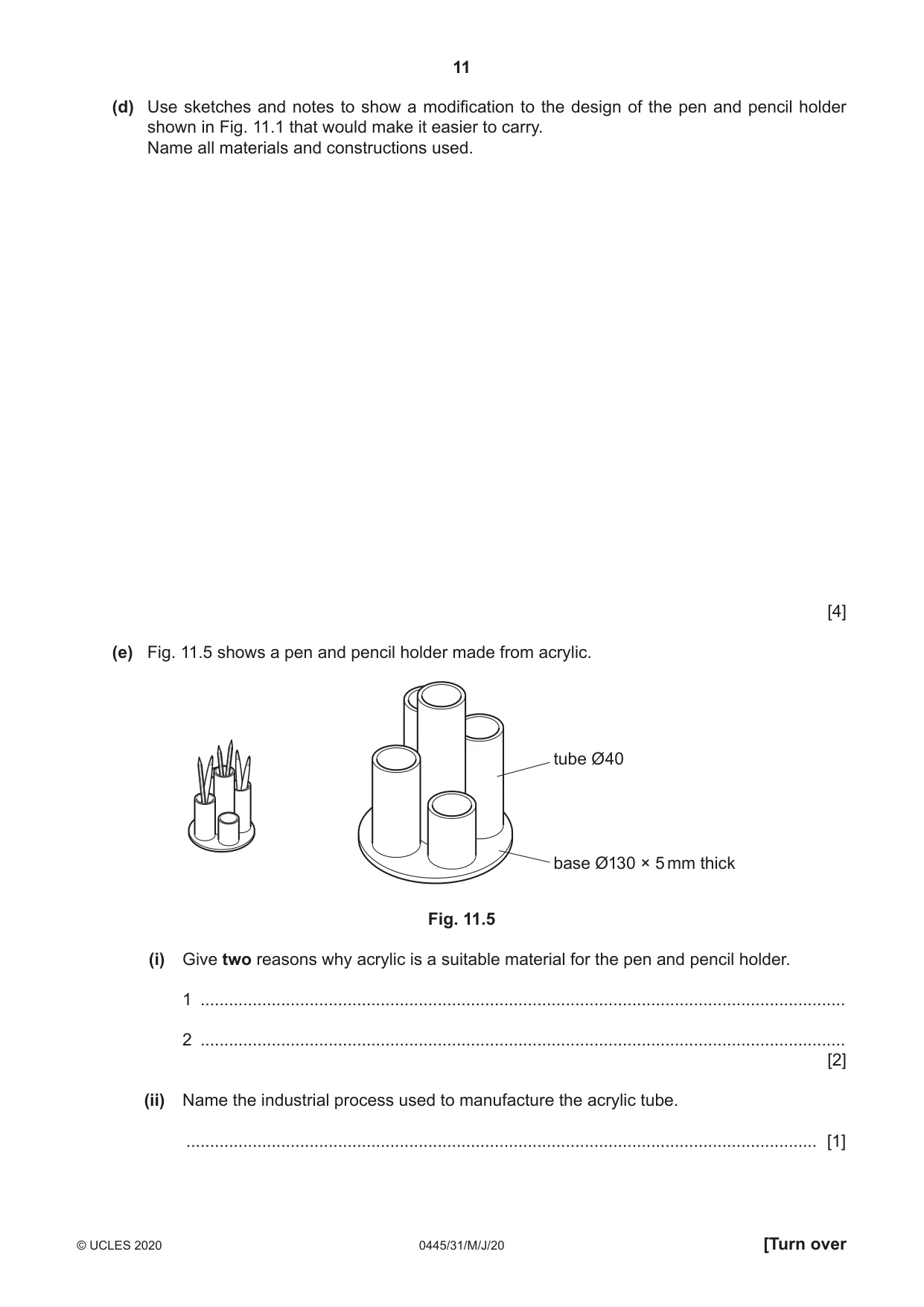
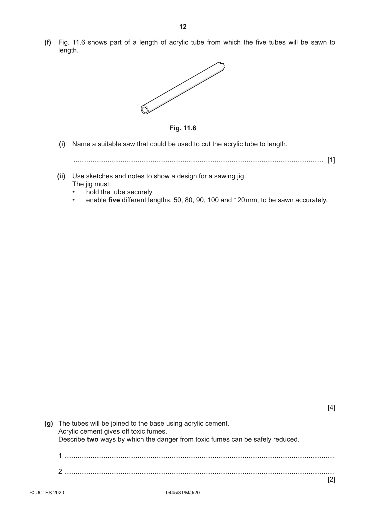
11 Fig. 11.1 shows a pen and pencil holder. top: 1.5 mm thick brass leg: brass rod Ø6 base: 12 mm thick beech 135 135 Fig. 11.1 (a) Fig. 11.2 shows the top part of the pen and pencil holder with the four shapes marked out. shapes 40 × 40 20 Fig. 11.2 Use sketches and notes to show how one of the shapes could be cut out and the edges made flat and smooth. Name all the tools and equipment used. [4] (b) Fig. 11.3 shows how the legs are fitted to the top of the pen and pencil holder by means of screw threads. screw thread inside hole screw thread leg Fig. 11.3 (i) Name the tool that could be used to cut the screw thread: on the end of the leg ........................................................................................................................................... inside the hole. ........................................................................................................................................... [2] (ii) The screw thread could be replaced by a permanent method of fixing. Circle from the list below a suitable permanent method of joining the legs to the top of the pen and pencil holder. welding brazing soldering [1] (c) Fig. 11.4 shows details of the shapes to be cut out of the base of the pen and pencil holder. A drill bit has been used to remove most of the waste wood in one of the shapes. finished shape 6 mm deep waste drilled hole 12 remaining waste Fig. 11.4 (i) Use sketches and notes to show how the remaining waste wood could be removed to produce an accurate finished shape. [3] (ii) Give one benefit of using a close-grained hardwood for the base of the pen and pencil holder. ........................................................................................................................................... ..................................................................................................................................... [1] (d) Use sketches and notes to show a modification to the design of the pen and pencil holder shown in Fig. 11.1 that would make it easier to carry. Name all materials and constructions used. [4] (e) Fig. 11.5 shows a pen and pencil holder made from acrylic. tube Ø40 base Ø130 × 5 mm thick Fig. 11.5 (i) Give two reasons why acrylic is a suitable material for the pen and pencil holder. 1 ........................................................................................................................................ 2 ........................................................................................................................................ [2] (ii) Name the industrial process used to manufacture the acrylic tube. ..................................................................................................................................... [1] (f) Fig. 11.6 shows part of a length of acrylic tube from which the five tubes will be sawn to length. Fig. 11.6 (i) Name a suitable saw that could be used to cut the acrylic tube to length. ..................................................................................................................................... [1] (ii) Use sketches and notes to show a design for a sawing jig. The jig must: • hold the tube securely • enable five different lengths, 50, 80, 90, 100 and 120 mm, to be sawn accurately. [4] (g) The tubes will be joined to the base using acrylic cement. Acrylic cement gives off toxic fumes. Describe two ways by which the danger from toxic fumes can be safely reduced. 1 ................................................................................................................................................ 2 ................................................................................................................................................ [2]
Mark scheme: 11(a) Drill small hole 1 4 Cut out waste with piercing saw 1 File to shape 1 Correctly named tools and equipment 1 11(b)(i) On end of leg: Die 1 2 Inside hole: Tap 1 11(b)(ii) Soldering 1 11(c)(i) Use of a chisel [and mallet] to remove waste 1 3 Work piece held securely [clamped] 1 Technical accuracy 1 11(c)(ii) Benefit: close grain is unlikely to split easily. 1 Provides a tough material. 11(d) Modification: some sort of ‘handle’ recognised 1 4 Practical method 1 Appropriate materials 1 Suitable constructions 1 11(e)(i) Acrylic suitable: colourful, self-finishing, easy to work to reqd. design 2 × 1 2 11(e)(ii) Extrusion/extrusion blow moulding 1 11(f)(i) Tenon saw, hacksaw, Hegner saw, band saw 1 11(f)(ii) Hold tube securely 1 4 Does not require measuring of tube to length 1 5 different lengths can be sawn 1 Ease of ‘changing’ different lengths 1 11(g) Two ways include: wear a face mask, well-ventilated room, extraction unit 2 2 × 1
Q12 · An incomplete design for a storage box made from wood
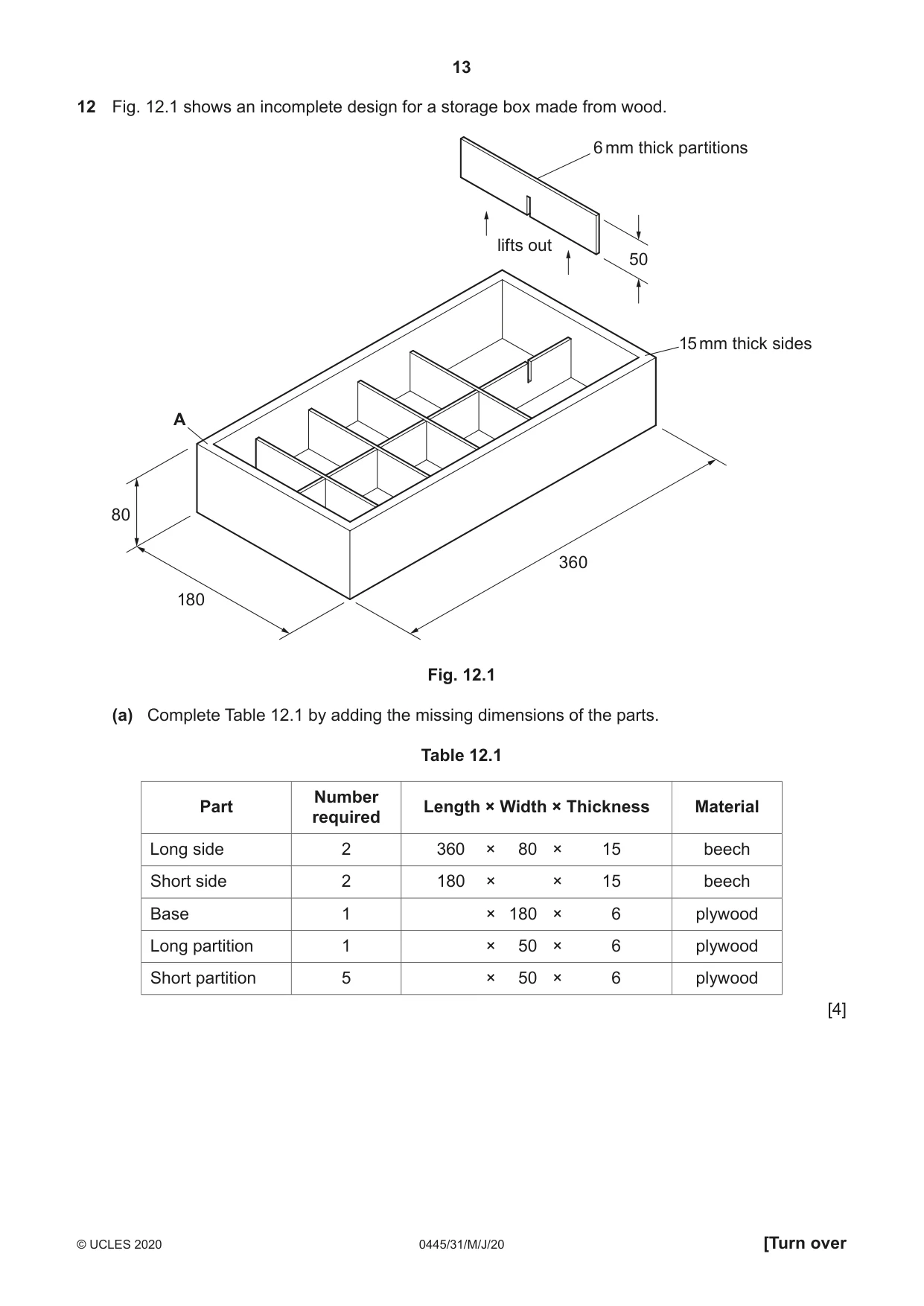
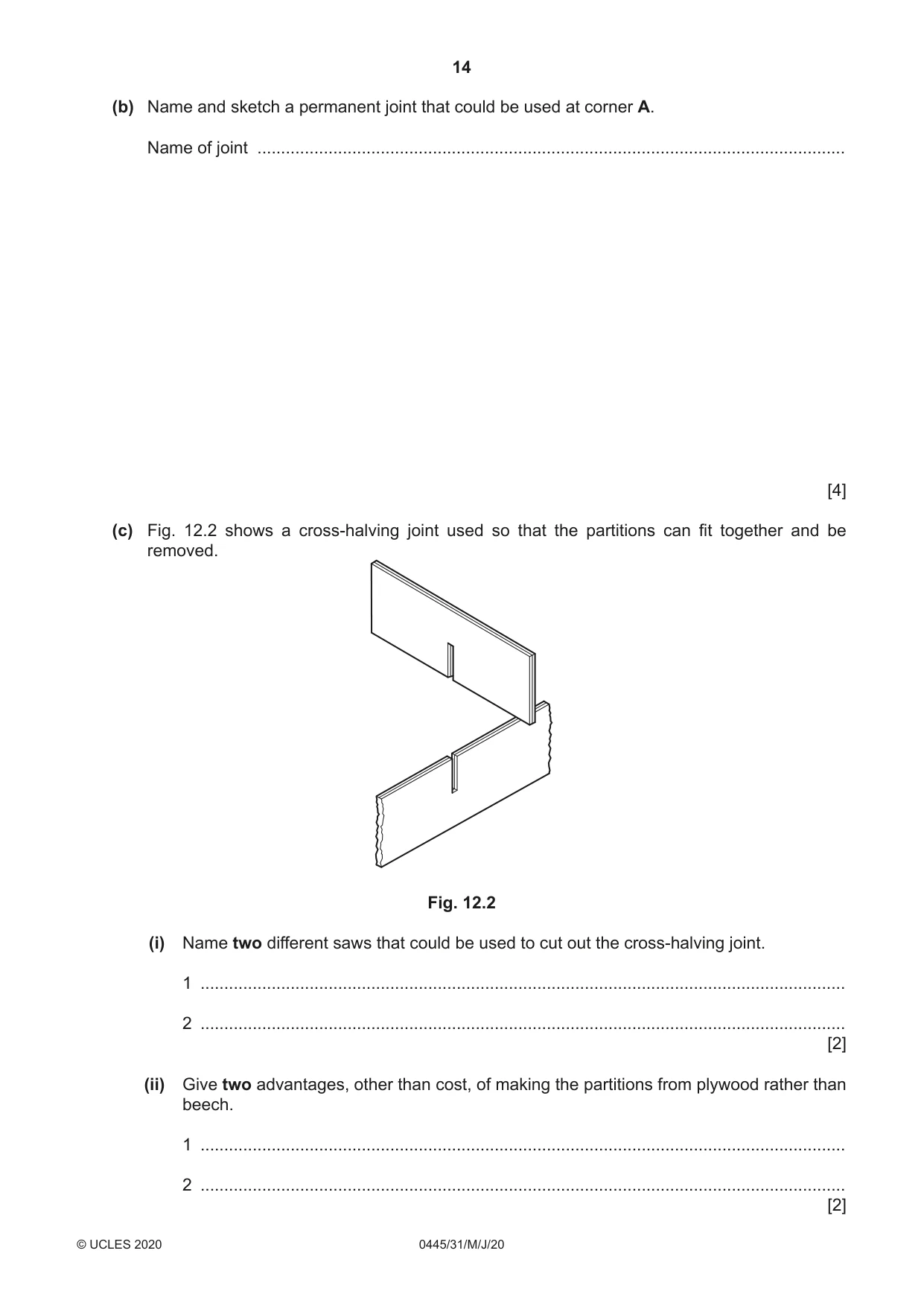
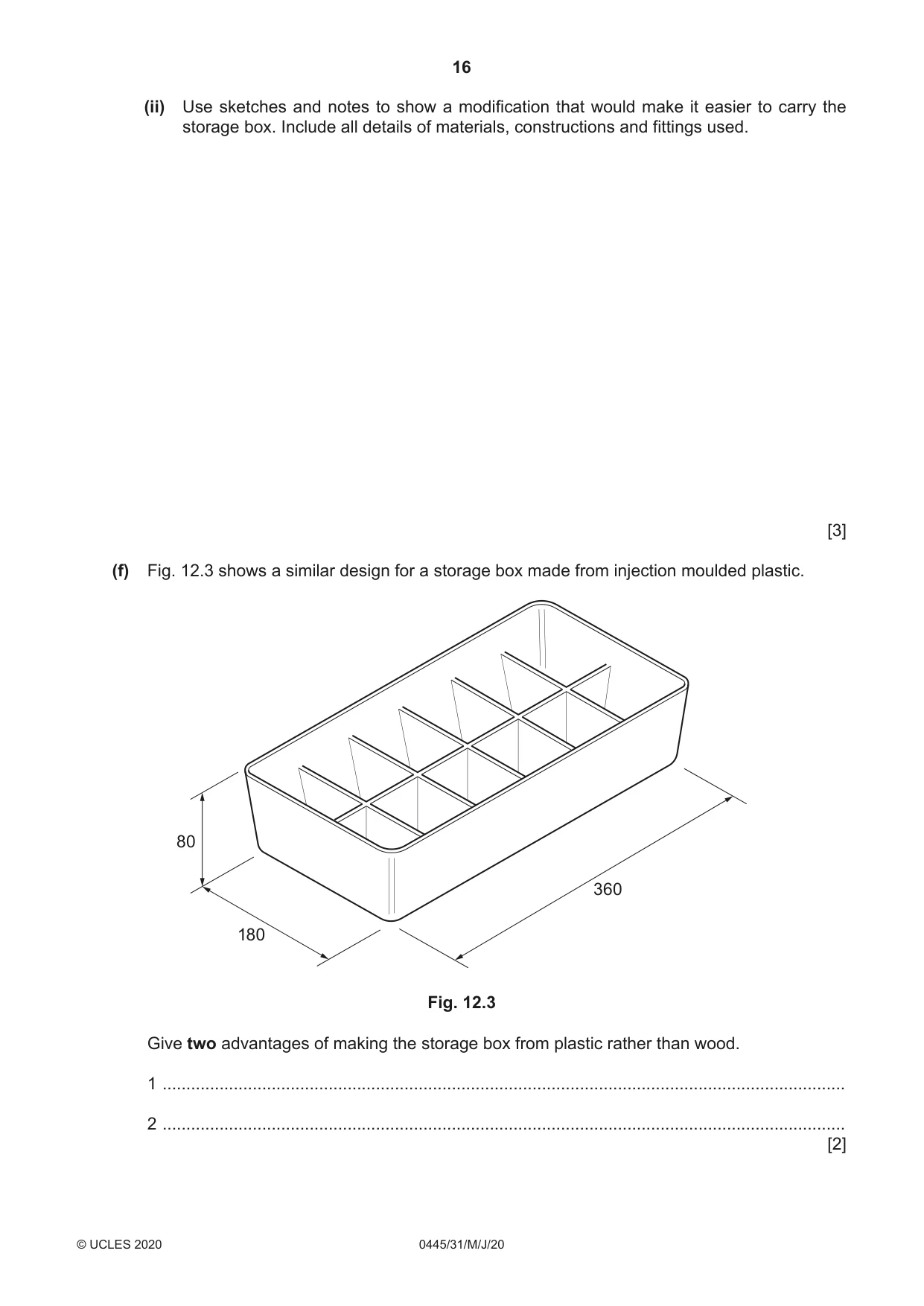
12 Fig. 12.1 shows an incomplete design for a storage box made from wood. 6 mm thick partitions lifts out 50 15 mm thick sides A 80 360 180 Fig. 12.1 (a) Complete Table 12.1 by adding the missing dimensions of the parts. Table 12.1 Number Part Length × Width × Thickness Material required Long side 2 360 × 80 × 15 beech Short side 2 180 × × 15 beech Base 1 × 180 × 6 plywood Long partition 1 × 50 × 6 plywood Short partition 5 × 50 × 6 plywood [4] (b) Name and sketch a permanent joint that could be used at corner A. Name of joint ............................................................................................................................ [4] (c) Fig. 12.2 shows a cross-halving joint used so that the partitions can fit together and be removed. Fig. 12.2 (i) Name two different saws that could be used to cut out the cross-halving joint. 1 ........................................................................................................................................ 2 ........................................................................................................................................ [2] (ii) Give two advantages, other than cost, of making the partitions from plywood rather than beech. 1 ........................................................................................................................................ 2 ........................................................................................................................................ [2] (d) Use sketches and notes to show a different method of keeping items separate inside a storage box. [3] (e) To complete the design of the storage box in Fig. 12.1 modifications need to be made. (i) Use sketches and notes to show a design for a lid that could be fitted to the storage box. Include all details of materials, constructions and fittings used. [5] (ii) Use sketches and notes to show a modification that would make it easier to carry the storage box. Include all details of materials, constructions and fittings used. [3] (f) Fig. 12.3 shows a similar design for a storage box made from injection moulded plastic. 80 360 180 Fig. 12.3 Give two advantages of making the storage box from plastic rather than wood. 1 ................................................................................................................................................ 2 ................................................................................................................................................ [2]
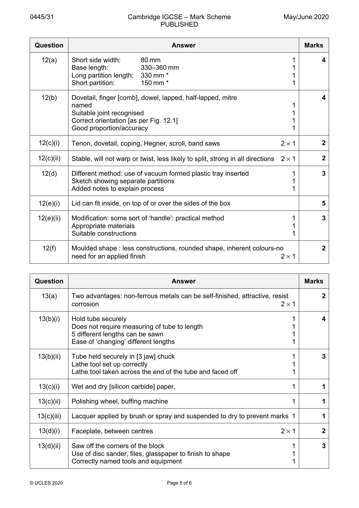
Mark scheme: 12(a) Short side width: 80 mm 1 4 Base length: 330–360 mm 1 Long partition length: 330 mm * 1 Short partition: 150 mm * 1 12(b) Dovetail, finger [comb], dowel, lapped, half-lapped, mitre 4 named 1 Suitable joint recognised 1 Correct orientation [as per Fig. 12.1] 1 Good proportion/accuracy 1 12(c)(i) Tenon, dovetail, coping, Hegner, scroll, band saws 2 × 1 2 12(c)(ii) Stable, will not warp or twist, less likely to split, strong in all directions 2 × 1 2 12(d) Different method: use of vacuum formed plastic tray inserted 1 3 Sketch showing separate partitions 1 Added notes to explain process 1 12(e)(i) Lid can fit inside, on top of or over the sides of the box 5 12(e)(ii) Modification: some sort of ‘handle’: practical method 1 3 Appropriate materials 1 Suitable constructions 1 12(f) Moulded shape : less constructions, rounded shape, inherent colours-no 2 need for an applied finish 2 × 1
Q13 · Wind chimes that will be batch produced in a school workshop
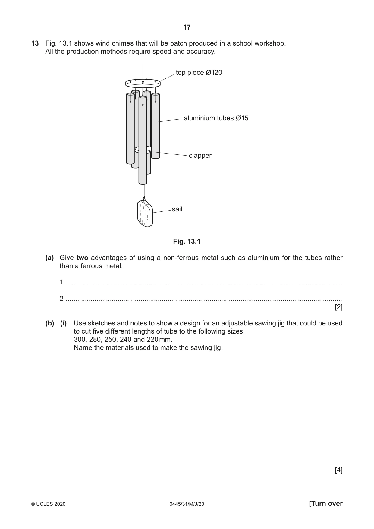
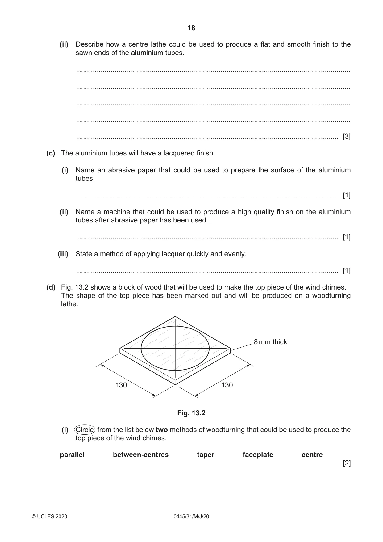
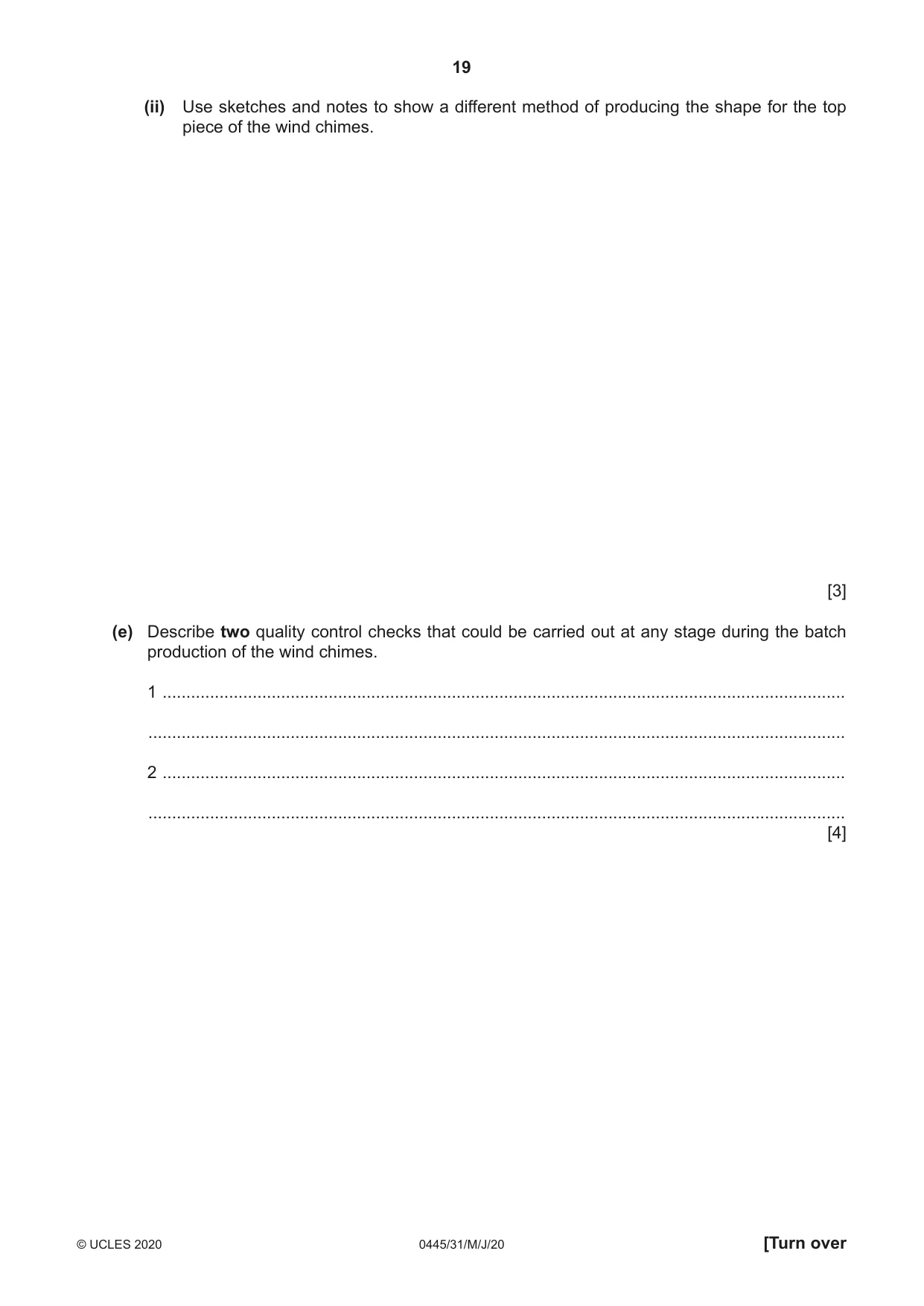
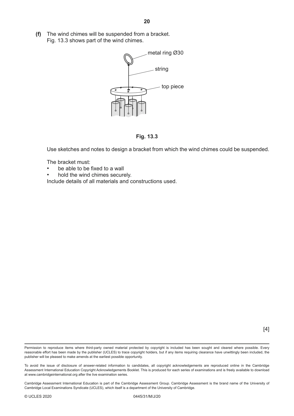
13 Fig. 13.1 shows wind chimes that will be batch produced in a school workshop. All the production methods require speed and accuracy. top piece Ø120 aluminium tubes Ø15 clapper sail Fig. 13.1 (a) Give two advantages of using a non-ferrous metal such as aluminium for the tubes rather than a ferrous metal. 1 ................................................................................................................................................ 2 ................................................................................................................................................ [2] (b) (i) Use sketches and notes to show a design for an adjustable sawing jig that could be used to cut five different lengths of tube to the following sizes: 300, 280, 250, 240 and 220 mm. Name the materials used to make the sawing jig. [4] (ii) Describe how a centre lathe could be used to produce a flat and smooth finish to the sawn ends of the aluminium tubes. ........................................................................................................................................... ........................................................................................................................................... ........................................................................................................................................... ........................................................................................................................................... ..................................................................................................................................... [3] (c) The aluminium tubes will have a lacquered finish. (i) Name an abrasive paper that could be used to prepare the surface of the aluminium tubes. ..................................................................................................................................... [1] (ii) Name a machine that could be used to produce a high quality finish on the aluminium tubes after abrasive paper has been used. ..................................................................................................................................... [1] (iii) State a method of applying lacquer quickly and evenly. ..................................................................................................................................... [1] (d) Fig. 13.2 shows a block of wood that will be used to make the top piece of the wind chimes. The shape of the top piece has been marked out and will be produced on a woodturning lathe. 8 mm thick 130 130 Fig. 13.2 (i) Circle from the list below two methods of woodturning that could be used to produce the top piece of the wind chimes. parallel between-centres taper faceplate centre [2] (ii) Use sketches and notes to show a different method of producing the shape for the top piece of the wind chimes. [3] (e) Describe two quality control checks that could be carried out at any stage during the batch production of the wind chimes. 1 ................................................................................................................................................ ................................................................................................................................................... 2 ................................................................................................................................................ ................................................................................................................................................... [4]
Mark scheme: 13(a) Two advantages: non-ferrous metals can be self-finished, attractive, resist 2 corrosion 2 × 1 13(b)(i) Hold tube securely 1 4 Does not require measuring of tube to length 1 5 different lengths can be sawn 1 Ease of ‘changing’ different lengths 1 13(b)(ii) Tube held securely in [3 jaw] chuck 1 3 Lathe tool set up correctly 1 Lathe tool taken across the end of the tube and faced off 1 13(c)(i) Wet and dry [silicon carbide] paper, 1 1 13(c)(ii) Polishing wheel, buffing machine 1 1 13(c)(iii) Lacquer applied by brush or spray and suspended to dry to prevent marks 1 1 13(d)(i) Faceplate, between centres 2 × 1 2 13(d)(ii) Saw off the corners of the block 1 3 Use of disc sander, files, glasspaper to finish to shape 1 Correctly named tools and equipment 1 13(e) Quality control checks include: dimension checks of various component 4 parts of the wind chimes, e.g. length of tube, positions of holes, diameter of top piece. Visual check on quality of finish. 2 × 2 13(f) Practical idea: allows bracket to be fixed to a wall 1 4 chimes secure 1 materials 1 constructions 1
What was in this paper
The subtopics covered by these 13 questions, and how many questions each got. Open one in a new tab to see every Cambridge question on it.