Cambridge IGCSE Design and Technology 0445 — 2019 Oct/Nov Paper 3 · Variant 2
0445/32/O/N/19 · 13 questions · 50 marks · ≈56 min
The question paper and its mark scheme, free to read here and free to download. This is Cambridge’s own paper, exactly as it was sat.
Question paper20 pages

Mark scheme6 pages
Answers below. Sit the paper first if you are practising.
Questions as text
Q1 · Complete the table by stating the manufacturing process used to make each plastic product
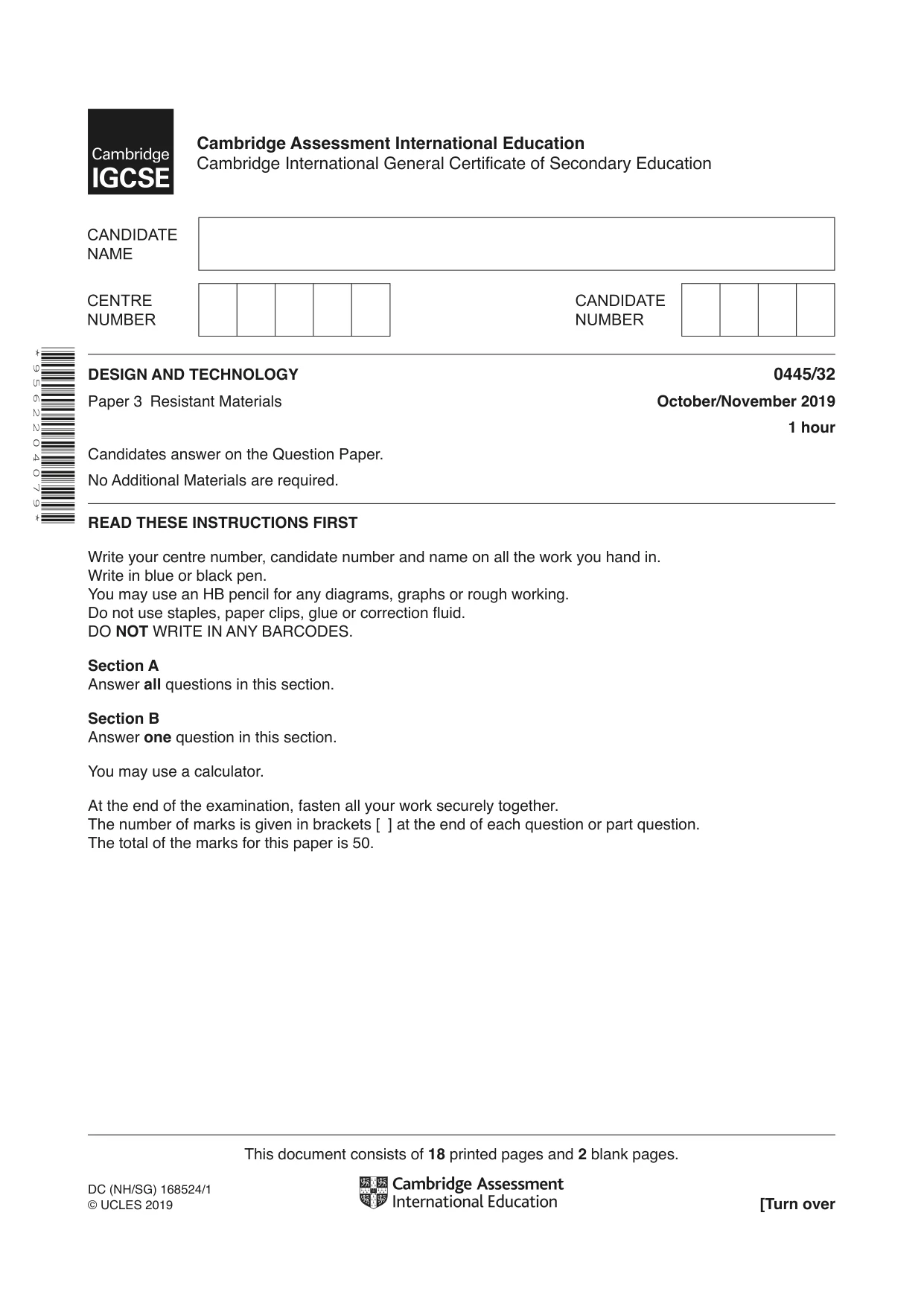
1 Complete the table by stating the manufacturing process used to make each plastic product. Plastic product Manufacturing process electrical plug guttering sandwich container [3]
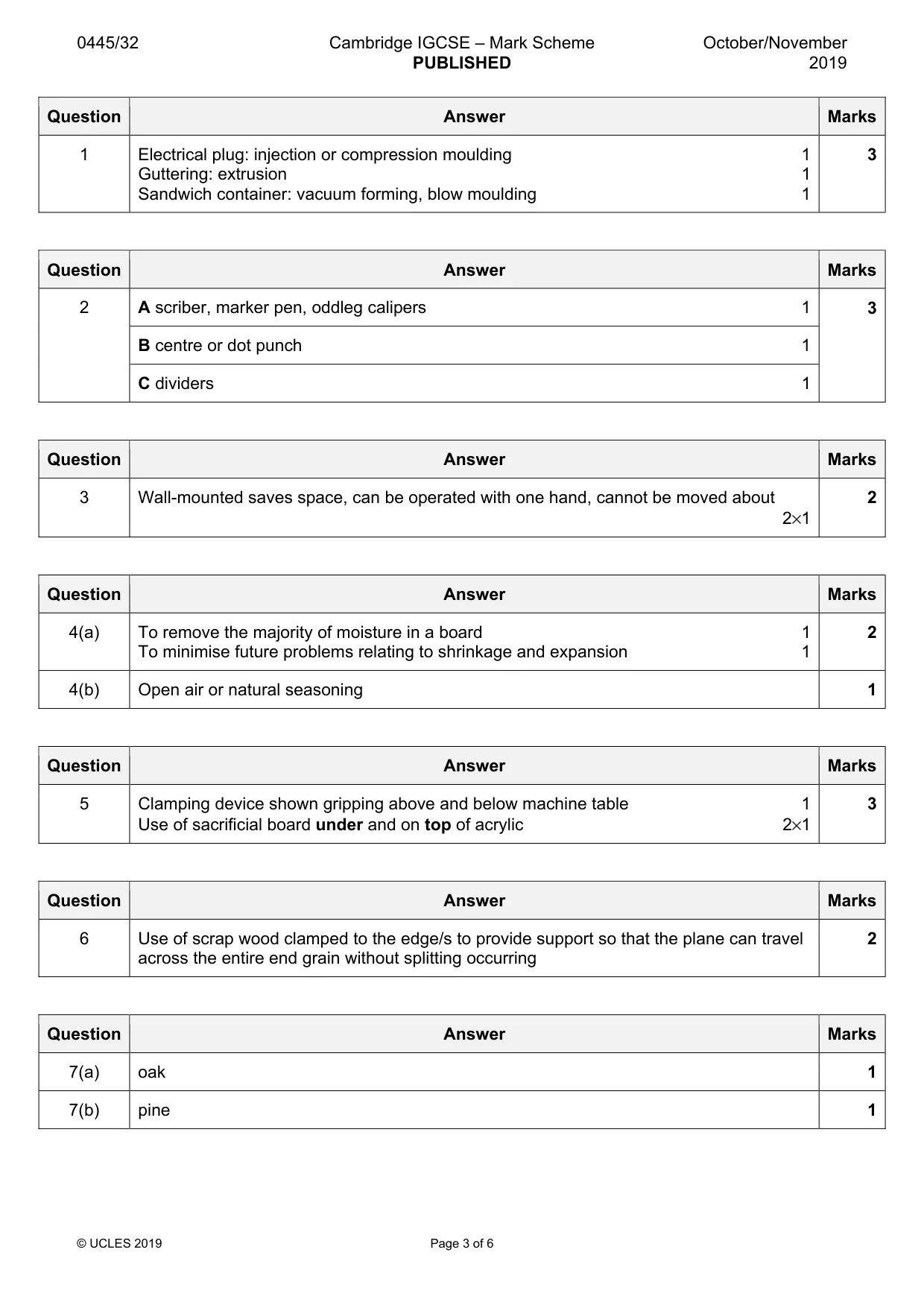
Mark scheme: Question Answer Marks 1 Electrical plug: injection or compression moulding 1 3 Guttering: extrusion 1 Sandwich container: vacuum forming, blow moulding 1
Q2 · A block of metal marked out ready to be drilled
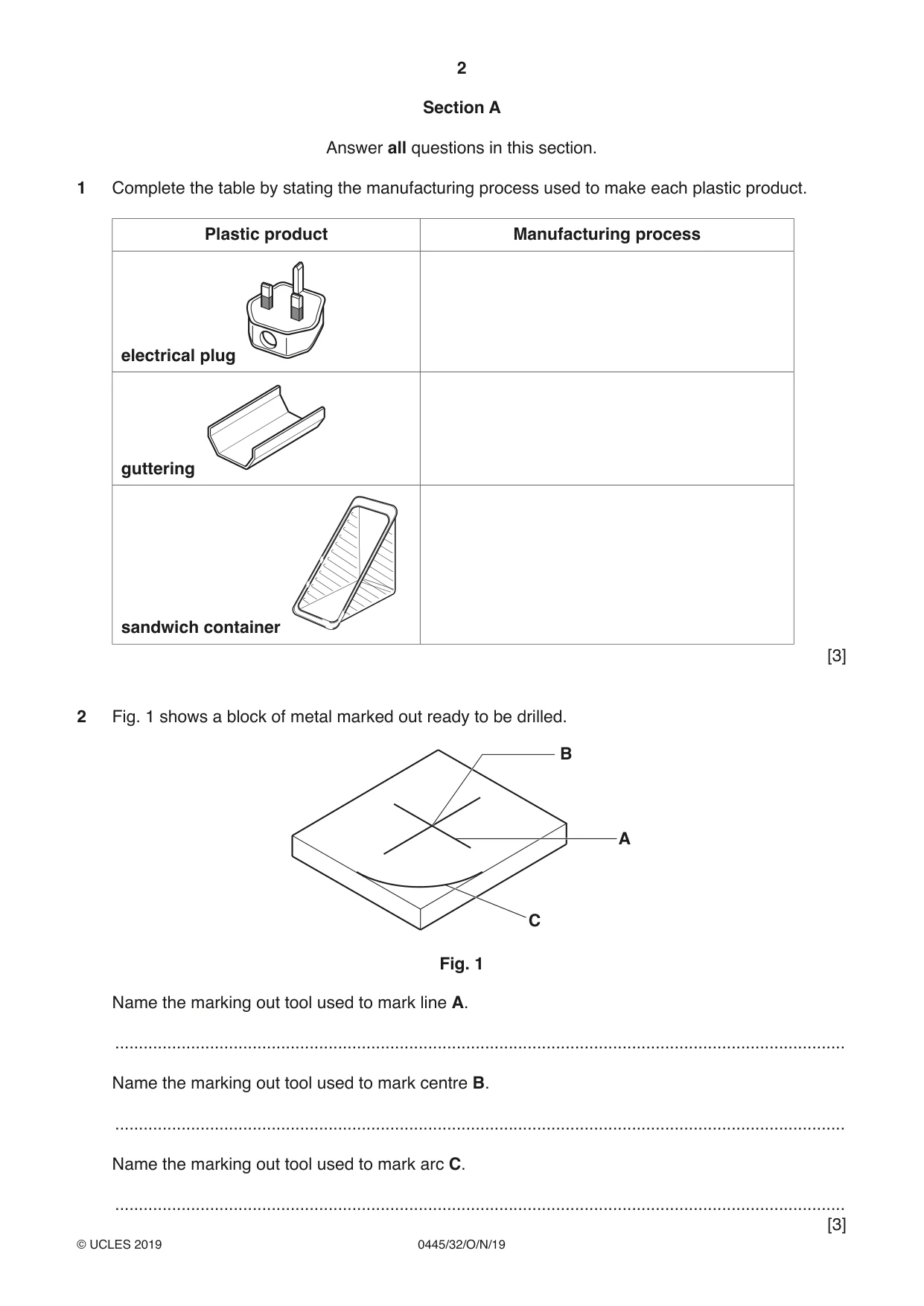
2 Fig. 1 shows a block of metal marked out ready to be drilled. B A C Fig. 1 Name the marking out tool used to mark line A. .......................................................................................................................................................... Name the marking out tool used to mark centre B. .......................................................................................................................................................... Name the marking out tool used to mark arc C. ..........................................................................................................................................................
Mark scheme: 2 A scriber, marker pen, oddleg calipers 1 3 B centre or dot punch 1 C dividers 1
Q3 · Two basic designs for kitchen roll holders
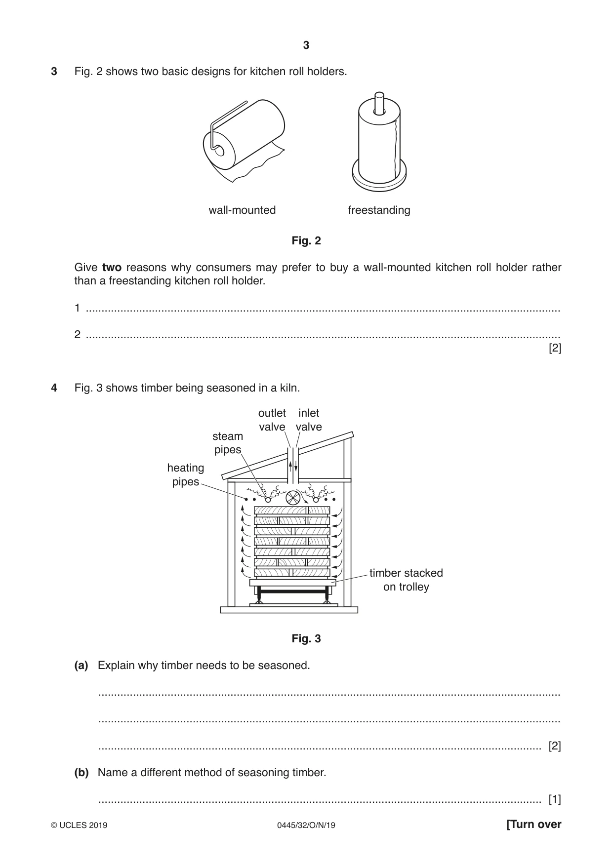
3 Fig. 2 shows two basic designs for kitchen roll holders. wall-mounted freestanding Fig. 2 Give two reasons why consumers may prefer to buy a wall-mounted kitchen roll holder rather than a freestanding kitchen roll holder. 1 ....................................................................................................................................................... 2 ....................................................................................................................................................... [2]
Mark scheme: 3 Wall-mounted saves space, can be operated with one hand, cannot be moved about 2 2×1
Q4 · Timber being seasoned in a kiln
4 Fig. 3 shows timber being seasoned in a kiln. outlet inlet valve valve steam pipes heating pipes timber stacked on trolley Fig. 3 (a) Explain why timber needs to be seasoned. ................................................................................................................................................... ................................................................................................................................................... ............................................................................................................................................. [2] (b) Name a different method of seasoning timber. ............................................................................................................................................. [1]
Mark scheme: 4(a) To remove the majority of moisture in a board 1 2 To minimise future problems relating to shrinkage and expansion 1 4(b) Open air or natural seasoning 1
Q5 · A Ø10 hole will be drilled in a sheet of 4 mm thick acrylic
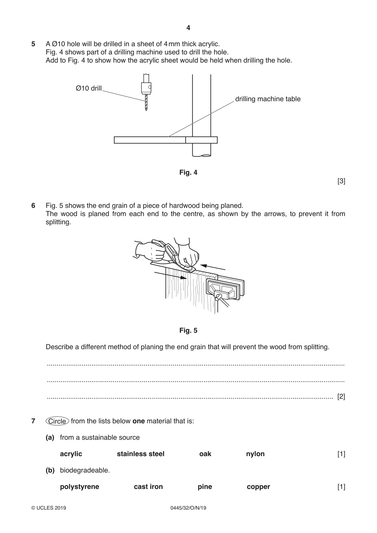
5 A Ø10 hole will be drilled in a sheet of 4 mm thick acrylic. Fig. 4 shows part of a drilling machine used to drill the hole. Add to Fig. 4 to show how the acrylic sheet would be held when drilling the hole. Ø10 drill drilling machine table Fig. 4 [3]
Mark scheme: 5 Clamping device shown gripping above and below machine table 1 3 Use of sacrificial board under and on top of acrylic 2×1
Q6 · The end grain of a piece of hardwood being planed
6 Fig. 5 shows the end grain of a piece of hardwood being planed. The wood is planed from each end to the centre, as shown by the arrows, to prevent it from splitting. Fig. 5 Describe a different method of planing the end grain that will prevent the wood from splitting. .......................................................................................................................................................... .......................................................................................................................................................... .................................................................................................................................................... [2]
Mark scheme: 6 Use of scrap wood clamped to the edge/s to provide support so that the plane can travel 2 across the entire end grain without splitting occurring
Q7 · Circle from the lists below one material that is: (a) from a sustainable source acrylic…
7 Circle from the lists below one material that is: (a) from a sustainable source acrylic stainless steel oak nylon [1] (b) biodegradeable. polystyrene cast iron pine copper [1]
Mark scheme: 7(a) oak 1 7(b) pine 1
Question 8
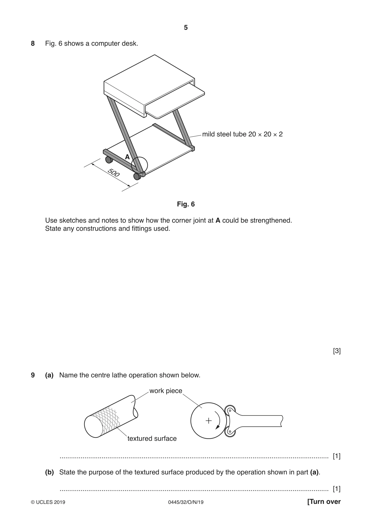
8 Fig. 6 shows a computer desk. mild steel tube 20 × 20 × 2 A 500 Fig. 6 Use sketches and notes to show how the corner joint at A could be strengthened. State any constructions and fittings used. [3]
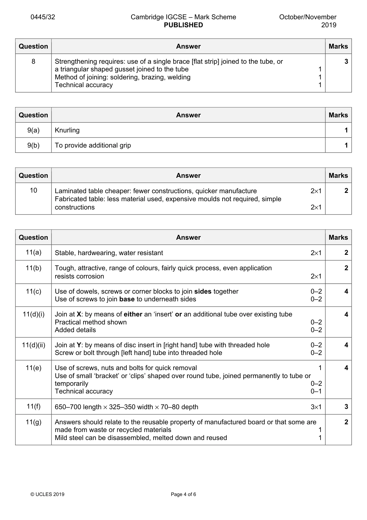
Mark scheme: 8 Strengthening requires: use of a single brace [flat strip] joined to the tube, or 3 a triangular shaped gusset joined to the tube 1 Method of joining: soldering, brazing, welding 1 Technical accuracy 1
Q9 · Name the centre lathe operation shown below
9 (a) Name the centre lathe operation shown below. work piece textured surface ............................................................................................................................................. [1] (b) State the purpose of the textured surface produced by the operation shown in part (a). ............................................................................................................................................. [1]
Mark scheme: 9(a) Knurling 1 9(b) To provide additional grip 1
Q10 · Two small wooden tables
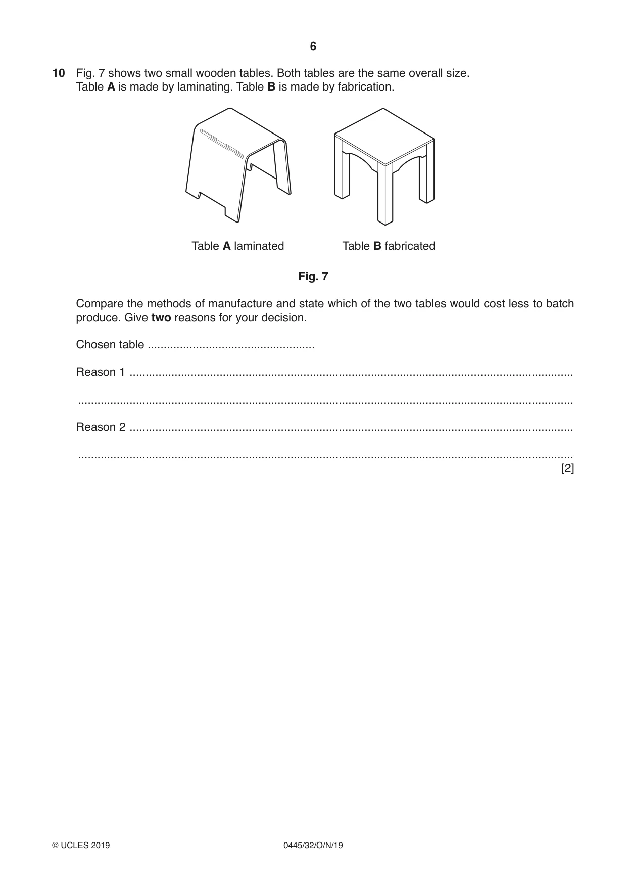
10 Fig. 7 shows two small wooden tables. Both tables are the same overall size. Table A is made by laminating. Table B is made by fabrication. Table A laminated Table B fabricated Fig. 7 Compare the methods of manufacture and state which of the two tables would cost less to batch produce. Give two reasons for your decision. Chosen table .................................................... Reason 1 .......................................................................................................................................... .......................................................................................................................................................... Reason 2 .......................................................................................................................................... .......................................................................................................................................................... [2]
Mark scheme: 10 Laminated table cheaper: fewer constructions, quicker manufacture 2×1 2 Fabricated table: less material used, expensive moulds not required, simple constructions 2×1
Q11 · Views of a planter box and stand
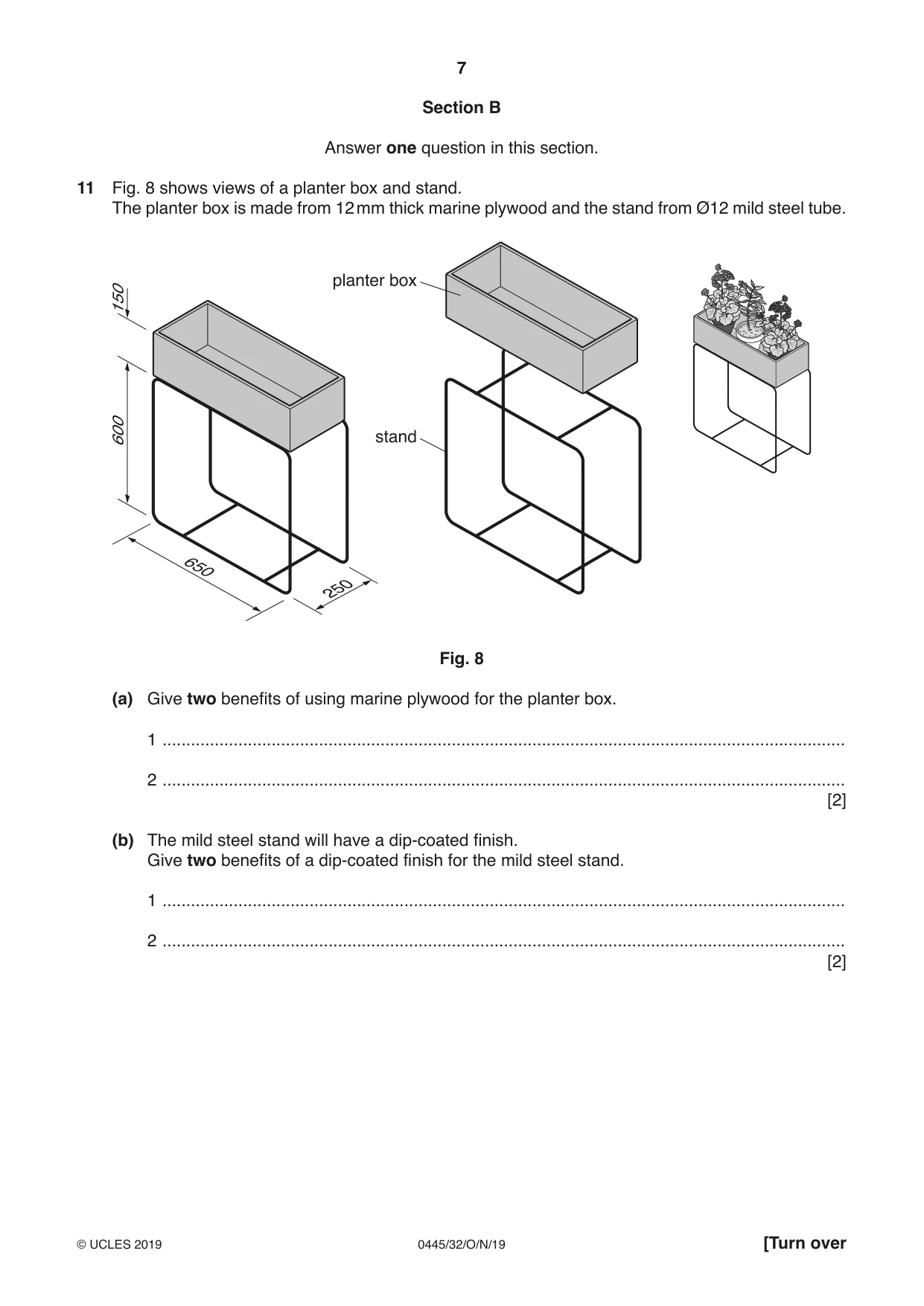
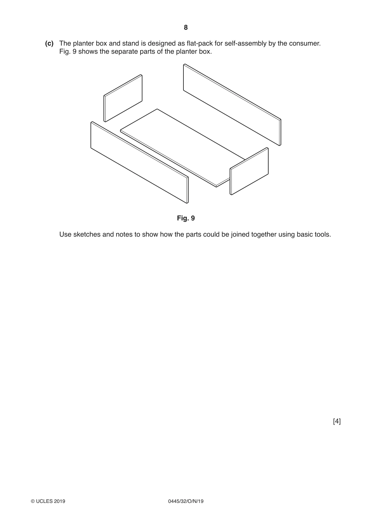
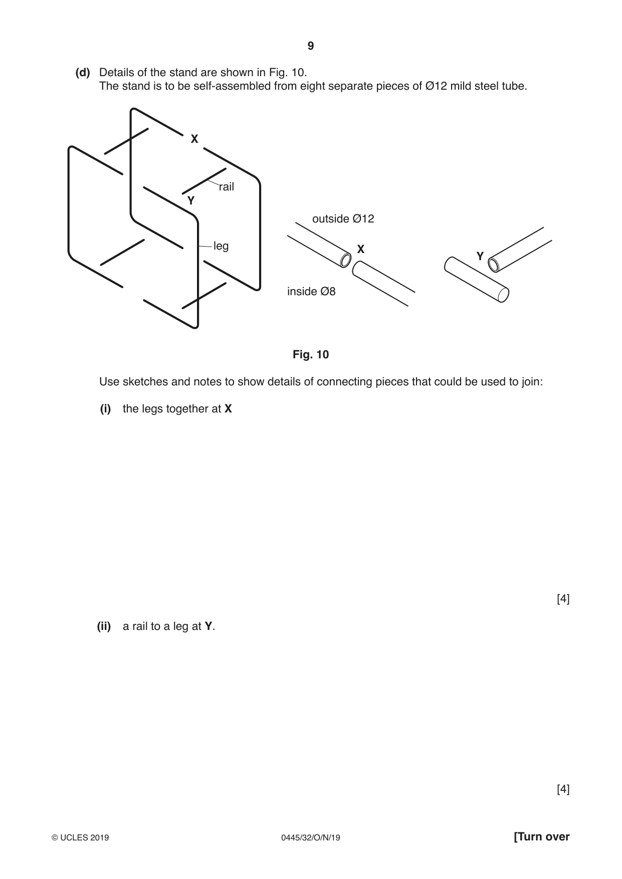
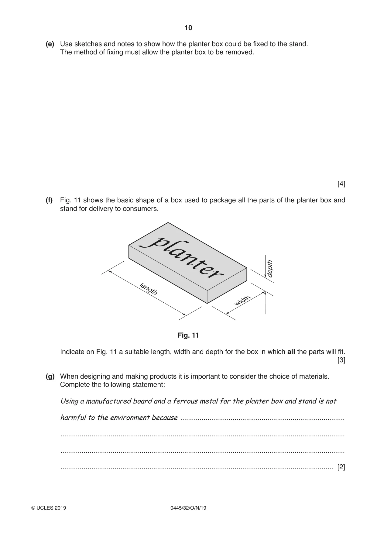
11 Fig. 8 shows views of a planter box and stand. The planter box is made from 12 mm thick marine plywood and the stand from Ø12 mild steel tube. planter box 150 600 stand 650 250 Fig. 8 (a) Give two benefits of using marine plywood for the planter box. 1 ................................................................................................................................................ 2 ................................................................................................................................................ [2] (b) The mild steel stand will have a dip-coated finish. Give two benefits of a dip-coated finish for the mild steel stand. 1 ................................................................................................................................................ 2 ................................................................................................................................................ [2] (c) The planter box and stand is designed as flat-pack for self-assembly by the consumer. Fig. 9 shows the separate parts of the planter box. Fig. 9 Use sketches and notes to show how the parts could be joined together using basic tools. [4] (d) Details of the stand are shown in Fig. 10. The stand is to be self-assembled from eight separate pieces of Ø12 mild steel tube. X rail Y outside Ø12 leg X Y inside Ø8 Fig. 10 Use sketches and notes to show details of connecting pieces that could be used to join: (i) the legs together at X [4] (ii) a rail to a leg at Y. [4] (e) Use sketches and notes to show how the planter box could be fixed to the stand. The method of fixing must allow the planter box to be removed. [4] (f) Fig. 11 shows the basic shape of a box used to package all the parts of the planter box and stand for delivery to consumers. depth length width Fig. 11 Indicate on Fig. 11 a suitable length, width and depth for the box in which all the parts will fit. [3] (g) When designing and making products it is important to consider the choice of materials. Complete the following statement: Usingamanufacturedboardandaferrousmetalfortheplanterboxandstandisnot harmfultotheenvironmentbecause ..................................................................................... ................................................................................................................................................... ................................................................................................................................................... ............................................................................................................................................. [2]
Mark scheme: 11(a) Stable, hardwearing, water resistant 2×1 2 11(b) Tough, attractive, range of colours, fairly quick process, even application 2 resists corrosion 2×1 11(c) Use of dowels, screws or corner blocks to join sides together 0–2 4 Use of screws to join base to underneath sides 0–2 11(d)(i) Join at X: by means of either an ‘insert’ or an additional tube over existing tube 4 Practical method shown 0–2 Added details 0–2 11(d)(ii) Join at Y: by means of disc insert in [right hand] tube with threaded hole 0–2 4 Screw or bolt through [left hand] tube into threaded hole 0–2 11(e) Use of screws, nuts and bolts for quick removal 1 4 Use of small ‘bracket’ or ‘clips’ shaped over round tube, joined permanently to tube or temporarily 0–2 Technical accuracy 0–1 11(f) 650–700 length × 325–350 width × 70–80 depth 3×1 3 11(g) Answers should relate to the reusable property of manufactured board or that some are 2 made from waste or recycled materials 1 Mild steel can be disassembled, melted down and reused 1
Q12 · Views of an incomplete design for a toy helicopter made from 6 mm thick plywood
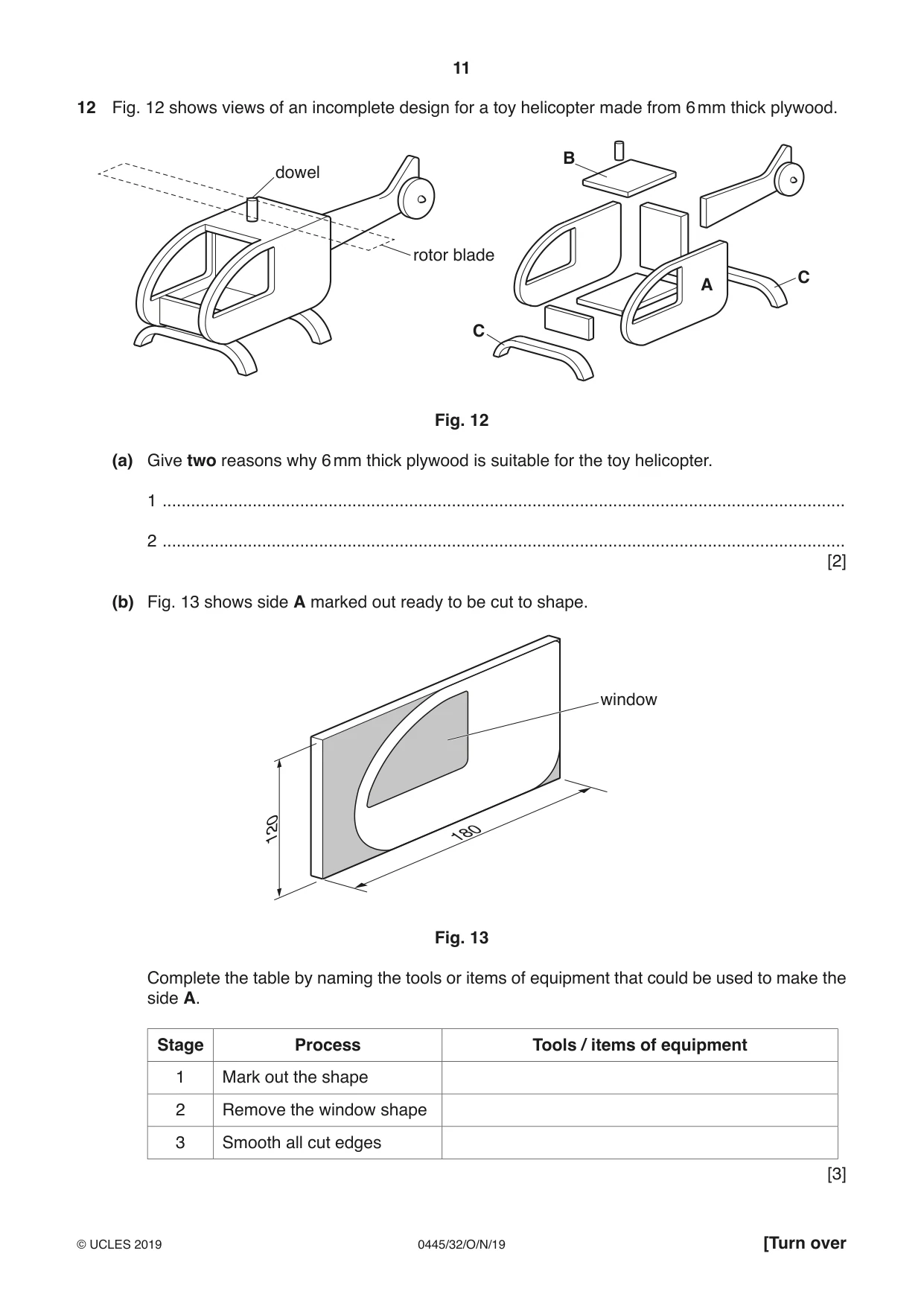
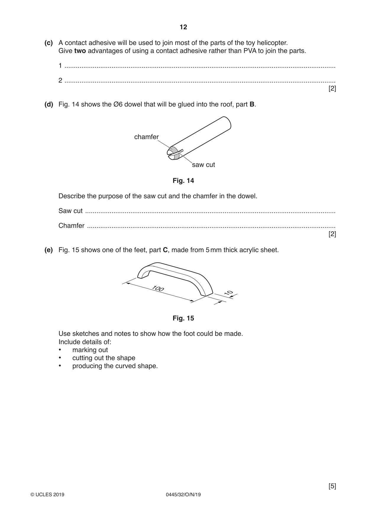
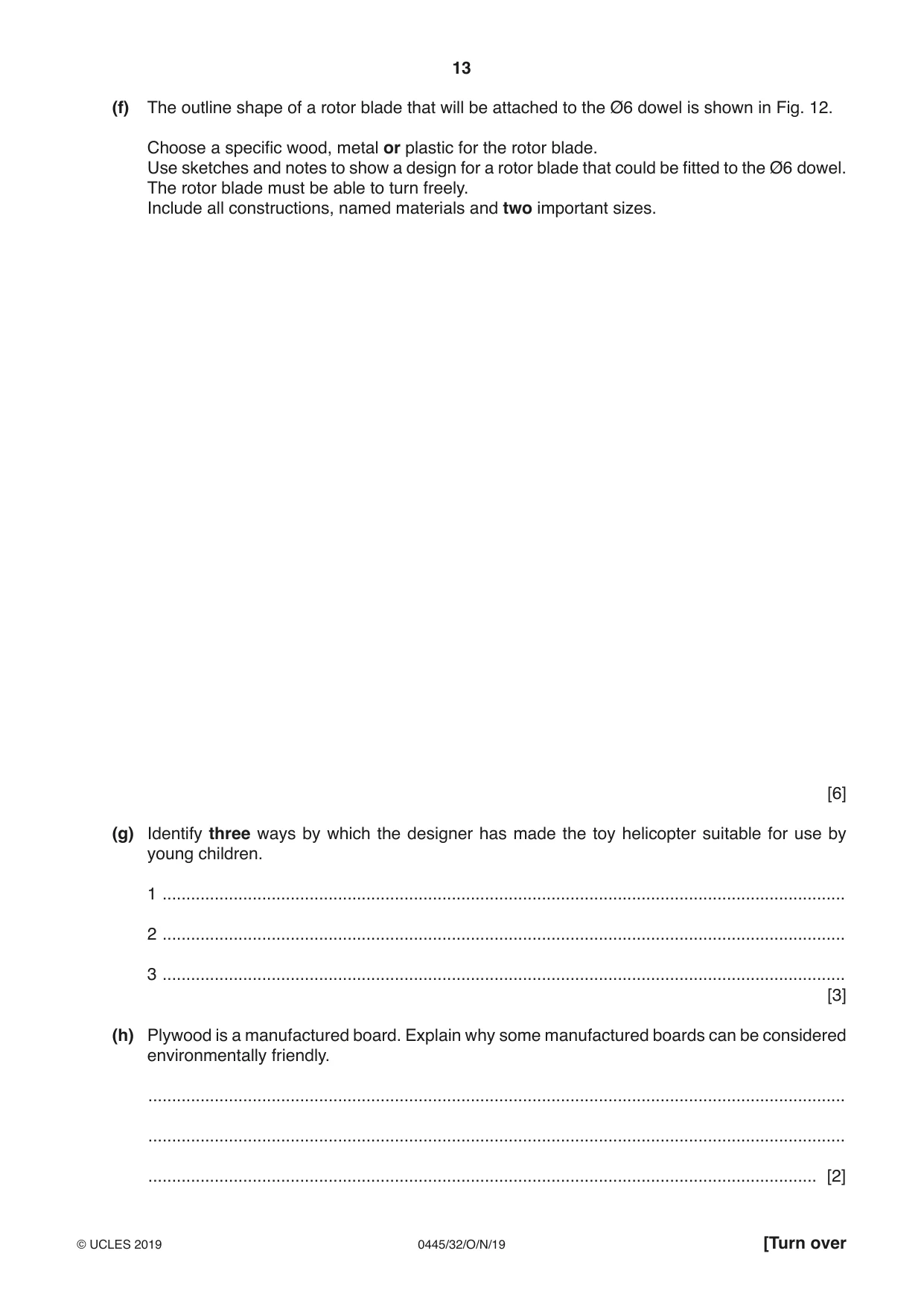
12 Fig. 12 shows views of an incomplete design for a toy helicopter made from 6 mm thick plywood. B dowel rotor blade C A C Fig. 12 (a) Give two reasons why 6 mm thick plywood is suitable for the toy helicopter. 1 ................................................................................................................................................ 2 ................................................................................................................................................ [2] (b) Fig. 13 shows side A marked out ready to be cut to shape. window 120 180 Fig. 13 Complete the table by naming the tools or items of equipment that could be used to make the side A. Stage Process Tools / items of equipment 1 Mark out the shape 2 Remove the window shape 3 Smooth all cut edges [3] (c) A contact adhesive will be used to join most of the parts of the toy helicopter. Give two advantages of using a contact adhesive rather than PVA to join the parts. 1 ................................................................................................................................................ 2 ................................................................................................................................................ [2] (d) Fig. 14 shows the Ø6 dowel that will be glued into the roof, part B. chamfer saw cut Fig. 14 Describe the purpose of the saw cut and the chamfer in the dowel. Saw cut ..................................................................................................................................... Chamfer .................................................................................................................................... [2] (e) Fig. 15 shows one of the feet, part C, made from 5 mm thick acrylic sheet. 100 10 Fig. 15 Use sketches and notes to show how the foot could be made. Include details of: • marking out • cutting out the shape • producing the curved shape. [5] (f) The outline shape of a rotor blade that will be attached to the Ø6 dowel is shown in Fig. 12. Choose a specific wood, metal or plastic for the rotor blade. Use sketches and notes to show a design for a rotor blade that could be fitted to the Ø6 dowel. The rotor blade must be able to turn freely. Include all constructions, named materials and two important sizes. [6] (g) Identify three ways by which the designer has made the toy helicopter suitable for use by young children. 1 ................................................................................................................................................ 2 ................................................................................................................................................ 3 ................................................................................................................................................ [3] (h) Plywood is a manufactured board. Explain why some manufactured boards can be considered environmentally friendly. ................................................................................................................................................... ................................................................................................................................................... ............................................................................................................................................. [2]
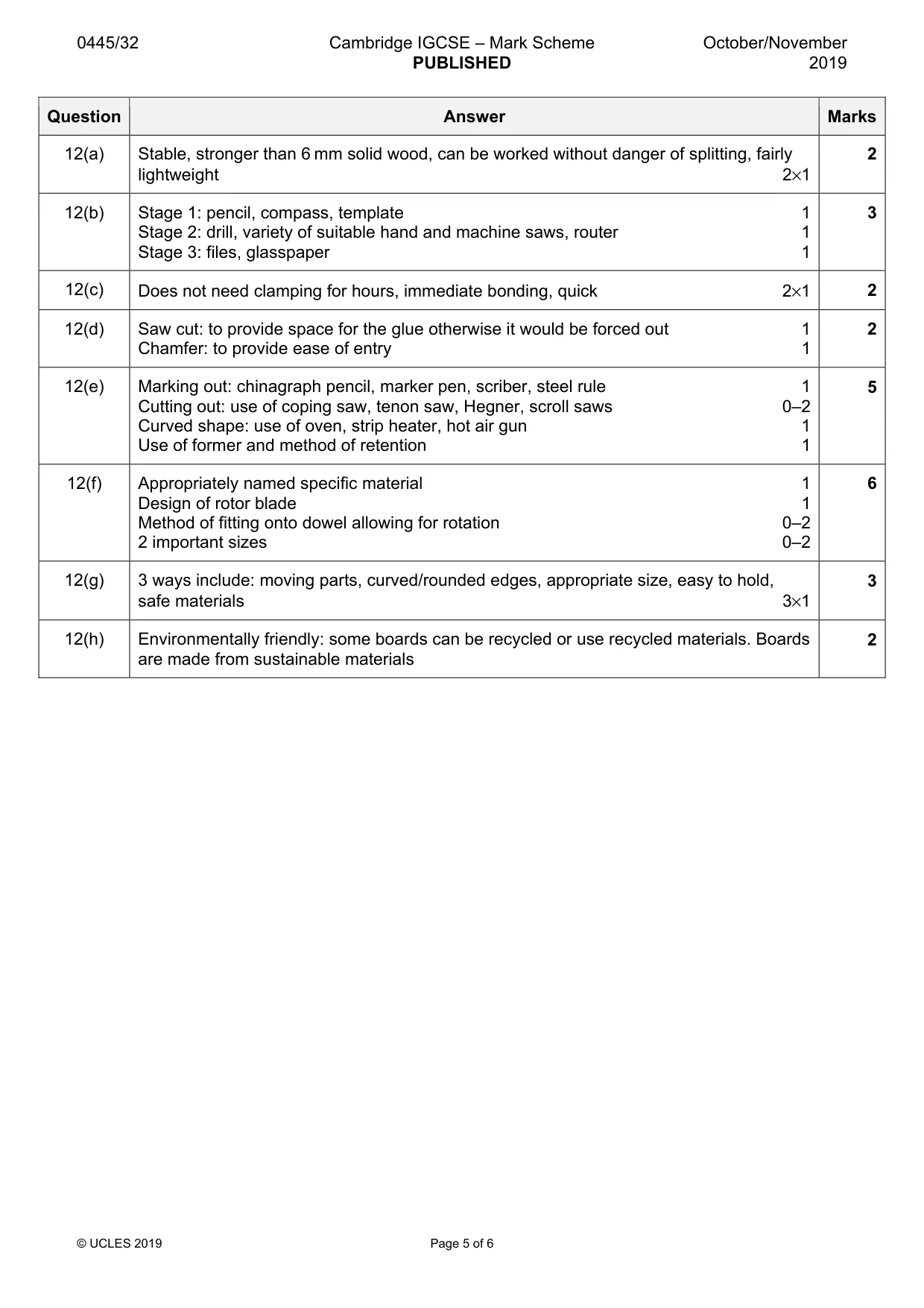
Mark scheme: 12(a) Stable, stronger than 6 mm solid wood, can be worked without danger of splitting, fairly 2 lightweight 2×1 12(b) Stage 1: pencil, compass, template 1 3 Stage 2: drill, variety of suitable hand and machine saws, router 1 Stage 3: files, glasspaper 1 12(c) Does not need clamping for hours, immediate bonding, quick 2×1 2 12(d) Saw cut: to provide space for the glue otherwise it would be forced out 1 2 Chamfer: to provide ease of entry 1 12(e) Marking out: chinagraph pencil, marker pen, scriber, steel rule 1 5 Cutting out: use of coping saw, tenon saw, Hegner, scroll saws 0–2 Curved shape: use of oven, strip heater, hot air gun 1 Use of former and method of retention 1 12(f) Appropriately named specific material 1 6 Design of rotor blade 1 Method of fitting onto dowel allowing for rotation 0–2 2 important sizes 0–2 12(g) 3 ways include: moving parts, curved/rounded edges, appropriate size, easy to hold, 3 safe materials 3×1 12(h) Environmentally friendly: some boards can be recycled or use recycled materials. Boards 2 are made from sustainable materials
Q13 · A ladder plant stand
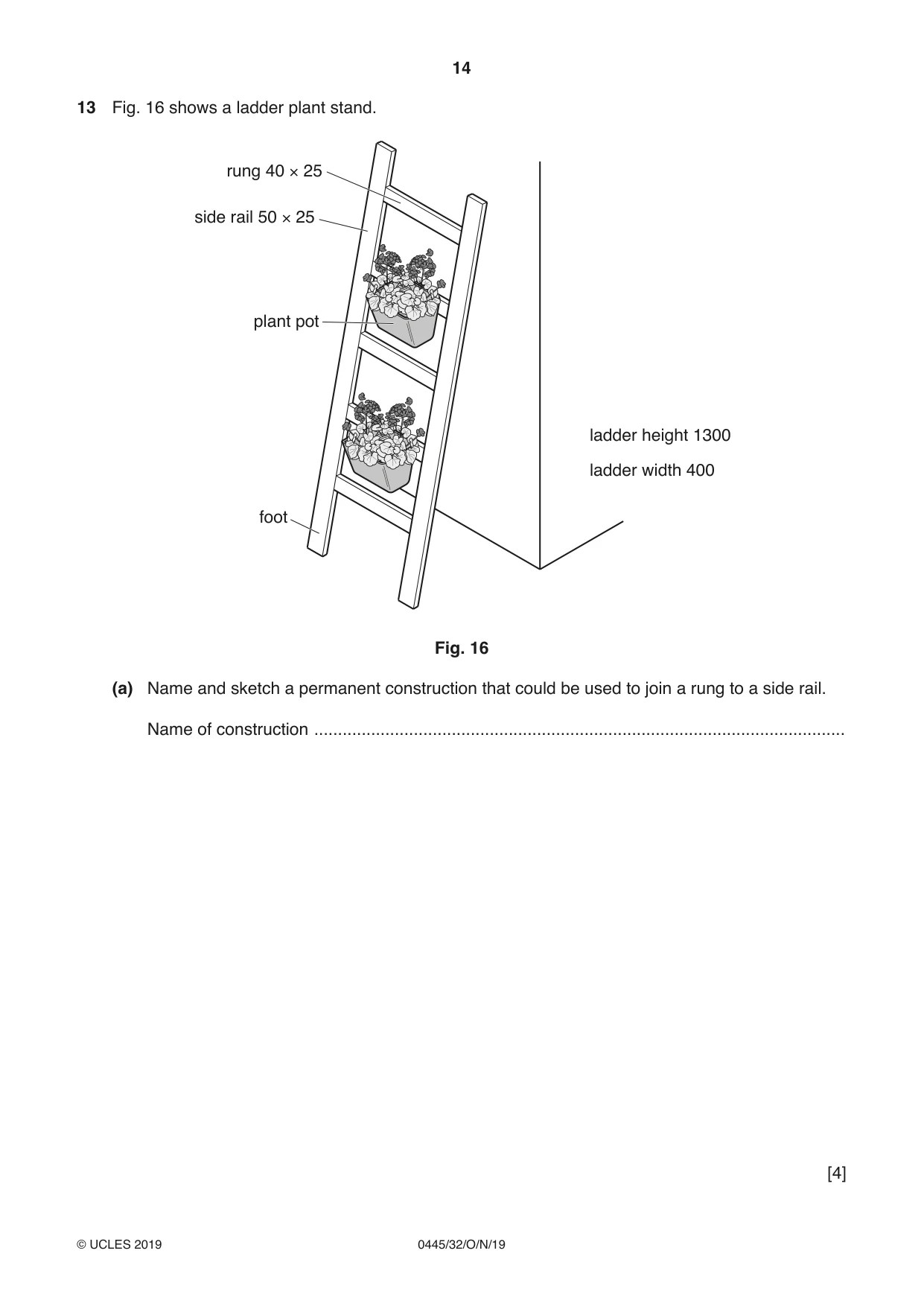
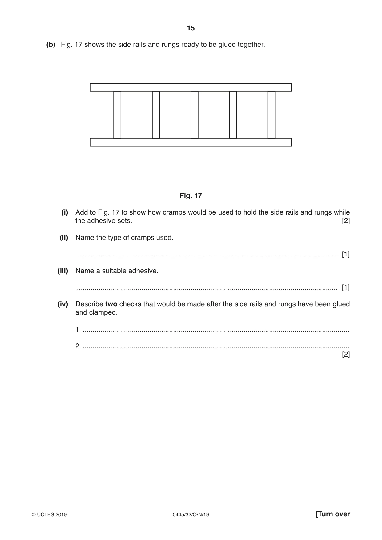
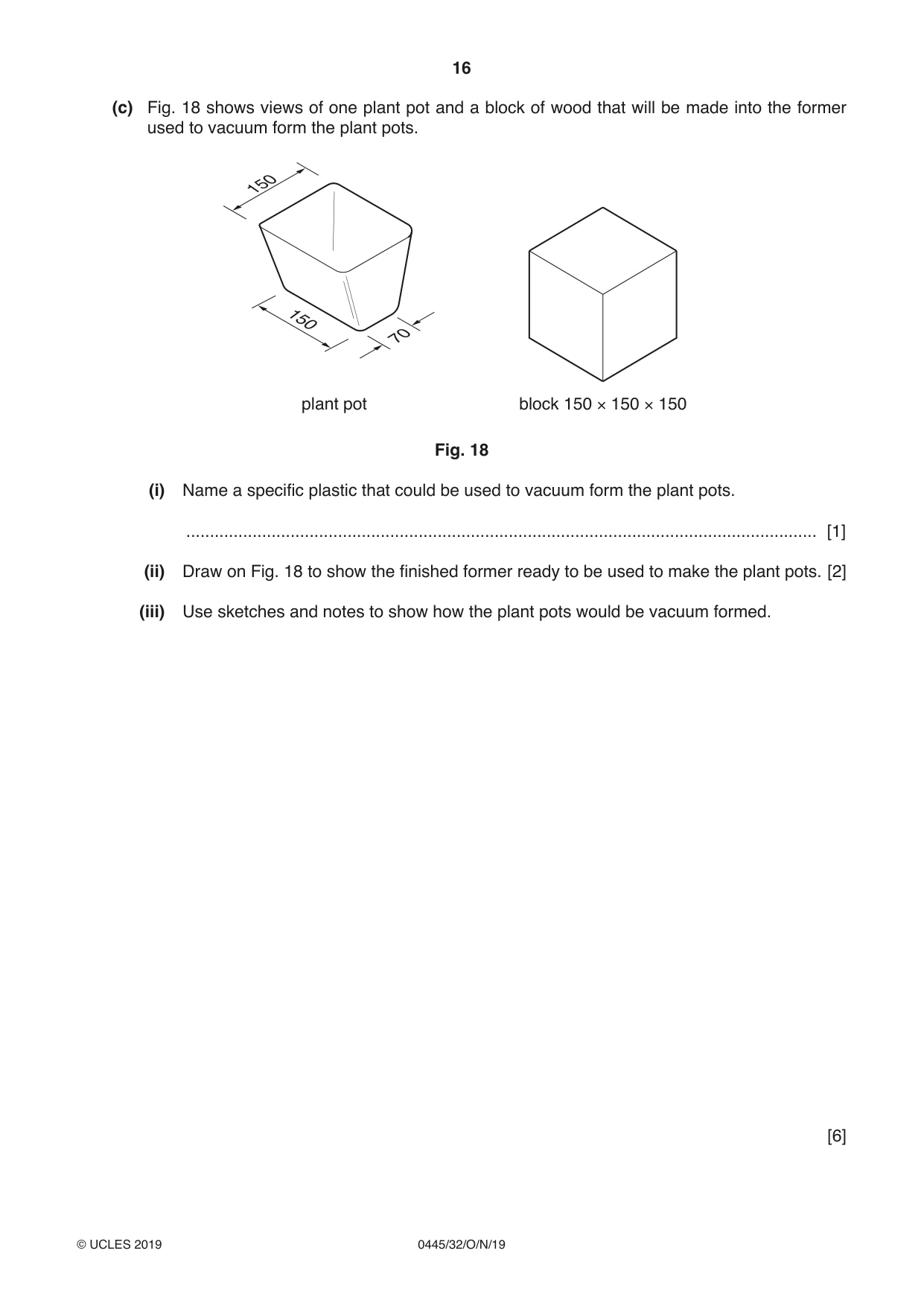
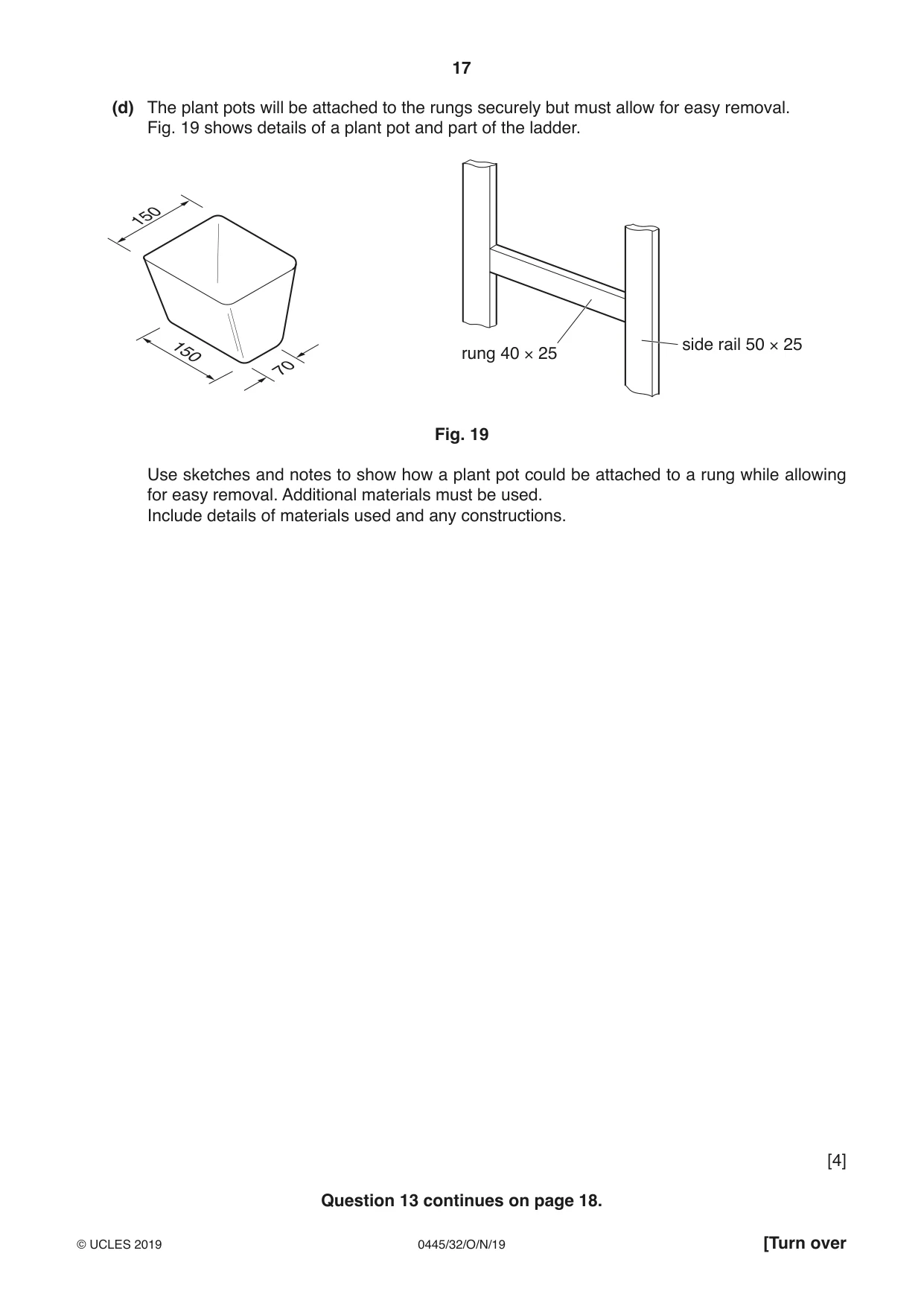
13 Fig. 16 shows a ladder plant stand. rung 40 × 25 side rail 50 × 25 plant pot ladder height 1300 ladder width 400 foot Fig. 16 (a) Name and sketch a permanent construction that could be used to join a rung to a side rail. Name of construction ................................................................................................................ [4] (b) Fig. 17 shows the side rails and rungs ready to be glued together. Fig. 17 (i) Add to Fig. 17 to show how cramps would be used to hold the side rails and rungs while the adhesive sets. [2] (ii) Name the type of cramps used. ..................................................................................................................................... [1] (iii) Name a suitable adhesive. ..................................................................................................................................... [1] (iv) Describe two checks that would be made after the side rails and rungs have been glued and clamped. 1 ........................................................................................................................................ 2 ........................................................................................................................................ [2] (c) Fig. 18 shows views of one plant pot and a block of wood that will be made into the former used to vacuum form the plant pots. 150 150 70 plant pot block 150 × 150 × 150 Fig. 18 (i) Name a specific plastic that could be used to vacuum form the plant pots. ..................................................................................................................................... [1] (ii) Draw on Fig. 18 to show the finished former ready to be used to make the plant pots. [2] (iii) Use sketches and notes to show how the plant pots would be vacuum formed. [6]
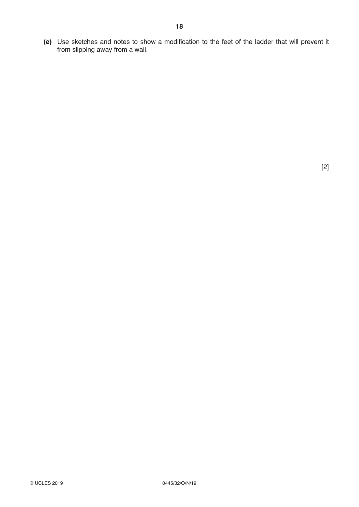
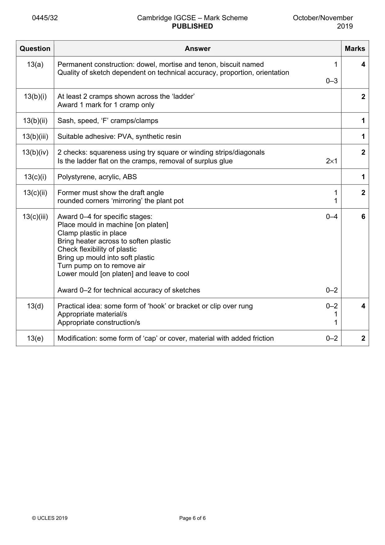
Mark scheme: 13(a) Permanent construction: dowel, mortise and tenon, biscuit named 1 4 Quality of sketch dependent on technical accuracy, proportion, orientation 0–3 13(b)(i) At least 2 cramps shown across the ‘ladder’ 2 Award 1 mark for 1 cramp only 13(b)(ii) Sash, speed, ‘F’ cramps/clamps 1 13(b)(iii) Suitable adhesive: PVA, synthetic resin 1 13(b)(iv) 2 checks: squareness using try square or winding strips/diagonals 2 Is the ladder flat on the cramps, removal of surplus glue 2×1 13(c)(i) Polystyrene, acrylic, ABS 1 13(c)(ii) Former must show the draft angle 1 2 rounded corners ‘mirroring’ the plant pot 1 13(c)(iii) Award 0–4 for specific stages: 0–4 6 Place mould in machine [on platen] Clamp plastic in place Bring heater across to soften plastic Check flexibility of plastic Bring up mould into soft plastic Turn pump on to remove air Lower mould [on platen] and leave to cool Award 0–2 for technical accuracy of sketches 0–2 13(d) Practical idea: some form of ‘hook’ or bracket or clip over rung 0–2 4 Appropriate material/s 1 Appropriate construction/s 1 13(e) Modification: some form of ‘cap’ or cover, material with added friction 0–2 2
What was in this paper
The subtopics covered by these 13 questions, and how many questions each got. Open one in a new tab to see every Cambridge question on it.
What you needed in this session
Cambridge’s own grade thresholds for 2019 Oct/Nov, Paper 3 · Variant 2. A higher threshold means an easier paper — the bar moves with how the cohort did.