Cambridge IGCSE Design and Technology 0445 — 2019 Oct/Nov Paper 3 · Variant 3
0445/33/O/N/19 · 13 questions · 50 marks · ≈56 min
The question paper and its mark scheme, free to read here and free to download. This is Cambridge’s own paper, exactly as it was sat.
Question paper20 pages

Mark scheme6 pages
Answers below. Sit the paper first if you are practising.
Questions as text
Question 1
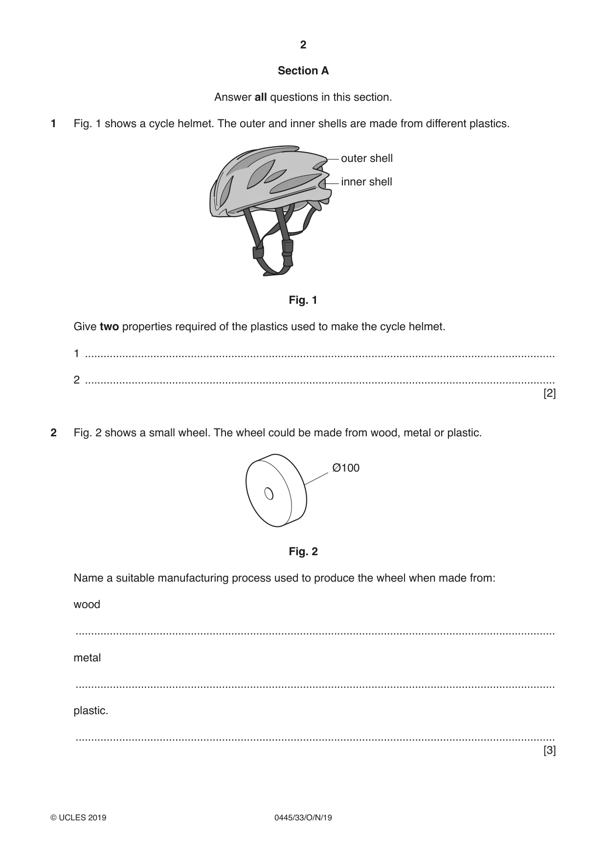
1 Fig. 1 shows a cycle helmet. The outer and inner shells are made from different plastics. outer shell inner shell Fig. 1 Give two properties required of the plastics used to make the cycle helmet. 1 ....................................................................................................................................................... 2 ....................................................................................................................................................... [2]
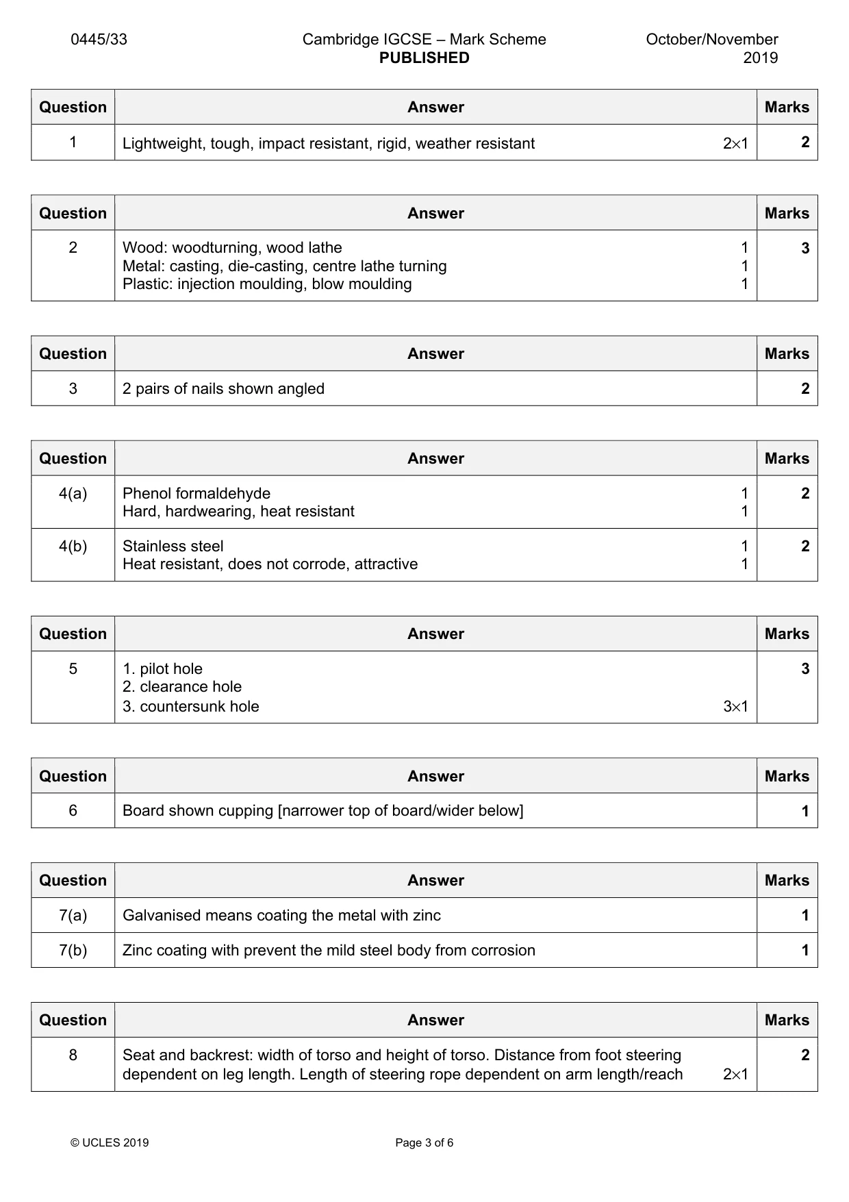
Mark scheme: Question Answer Marks 1 Lightweight, tough, impact resistant, rigid, weather resistant 2×1 2
Question 2
2 Fig. 2 shows a small wheel. The wheel could be made from wood, metal or plastic. Ø100 Fig. 2 Name a suitable manufacturing process used to produce the wheel when made from: wood .......................................................................................................................................................... metal .......................................................................................................................................................... plastic. .......................................................................................................................................................... [3]
Mark scheme: 2 Wood: woodturning, wood lathe 1 3 Metal: casting, die-casting, centre lathe turning 1 Plastic: injection moulding, blow moulding 1
Q3 · Two pieces of wood being glued together
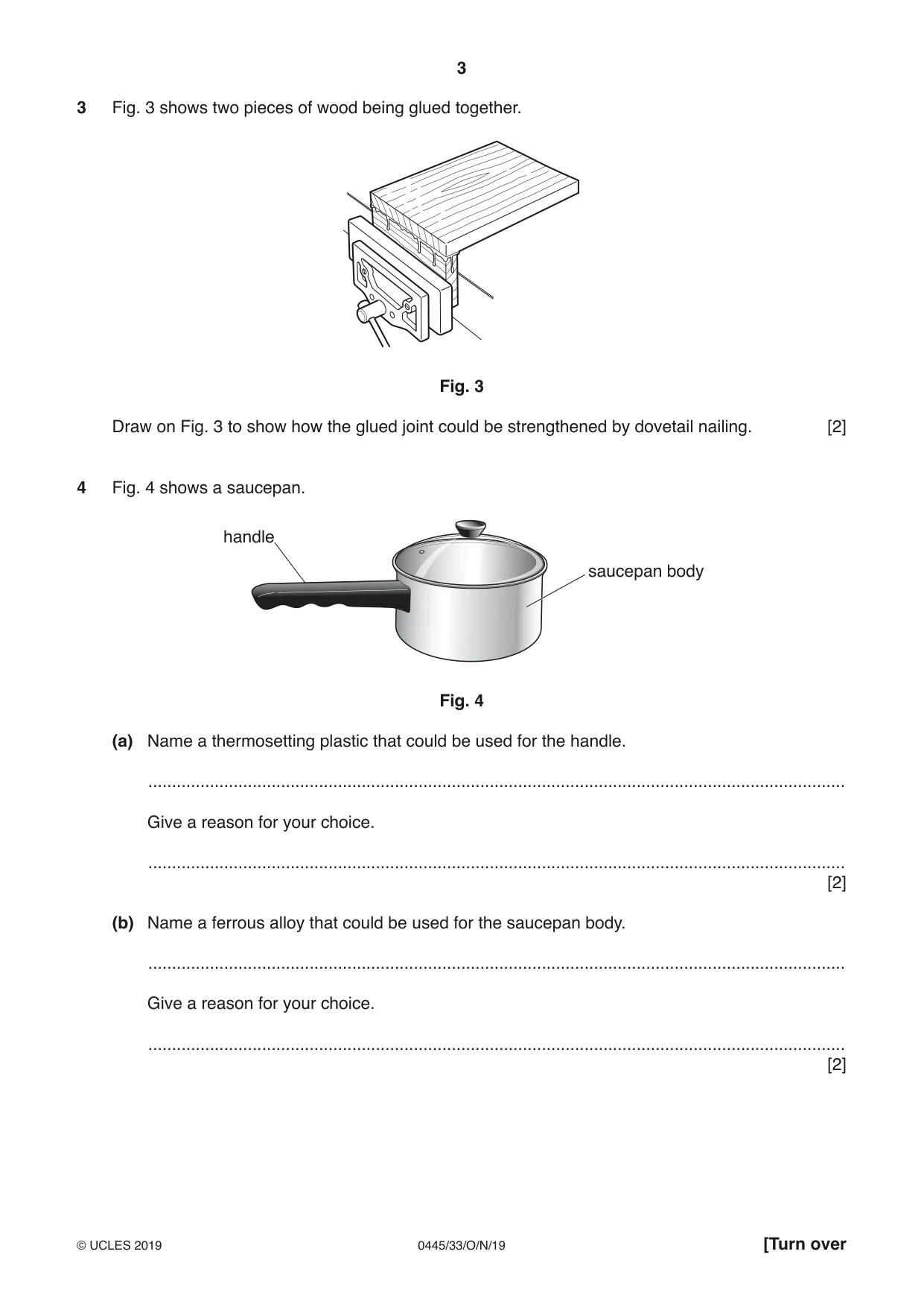
3 Fig. 3 shows two pieces of wood being glued together. Fig. 3 Draw on Fig. 3 to show how the glued joint could be strengthened by dovetail nailing. [2]
Mark scheme: 3 2 pairs of nails shown angled 2
Question 4
4 Fig. 4 shows a saucepan. handle saucepan body Fig. 4 (a) Name a thermosetting plastic that could be used for the handle. ................................................................................................................................................... Give a reason for your choice. ................................................................................................................................................... [2] (b) Name a ferrous alloy that could be used for the saucepan body. ................................................................................................................................................... Give a reason for your choice. ................................................................................................................................................... [2]
Mark scheme: 4(a) Phenol formaldehyde 1 2 Hard, hardwearing, heat resistant 1 4(b) Stainless steel 1 2 Heat resistant, does not corrode, attractive 1
Q5 · Three pre-drilled holes to take a screw
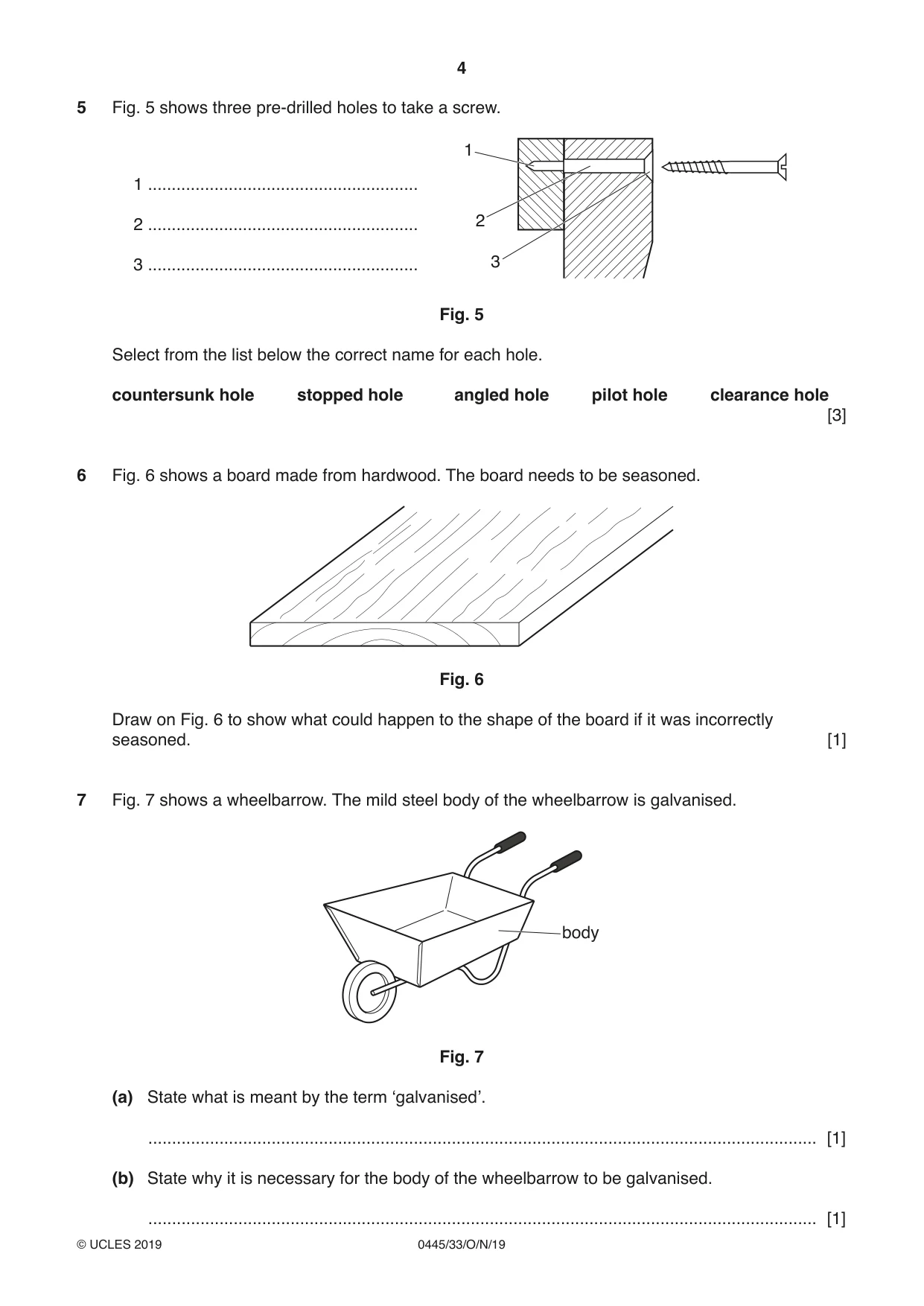
5 Fig. 5 shows three pre-drilled holes to take a screw. 1 1 ......................................................... 2 ......................................................... 2 3 ......................................................... 3 Fig. 5 Select from the list below the correct name for each hole. countersunk hole stopped hole angled hole pilot hole clearance hole [3]
Mark scheme: 5 1. pilot hole 3 2. clearance hole 3. countersunk hole 3×1
Q6 · A board made from hardwood
6 Fig. 6 shows a board made from hardwood. The board needs to be seasoned. Fig. 6 Draw on Fig. 6 to show what could happen to the shape of the board if it was incorrectly seasoned. [1]
Mark scheme: 6 Board shown cupping [narrower top of board/wider below] 1
Question 7
7 Fig. 7 shows a wheelbarrow. The mild steel body of the wheelbarrow is galvanised. body Fig. 7 (a) State what is meant by the term ‘galvanised’. ............................................................................................................................................. [1] (b) State why it is necessary for the body of the wheelbarrow to be galvanised. ............................................................................................................................................. [1]
Mark scheme: 7(a) Galvanised means coating the metal with zinc 1 7(b) Zinc coating with prevent the mild steel body from corrosion 1
Q8 · A child’s push-along go-kart
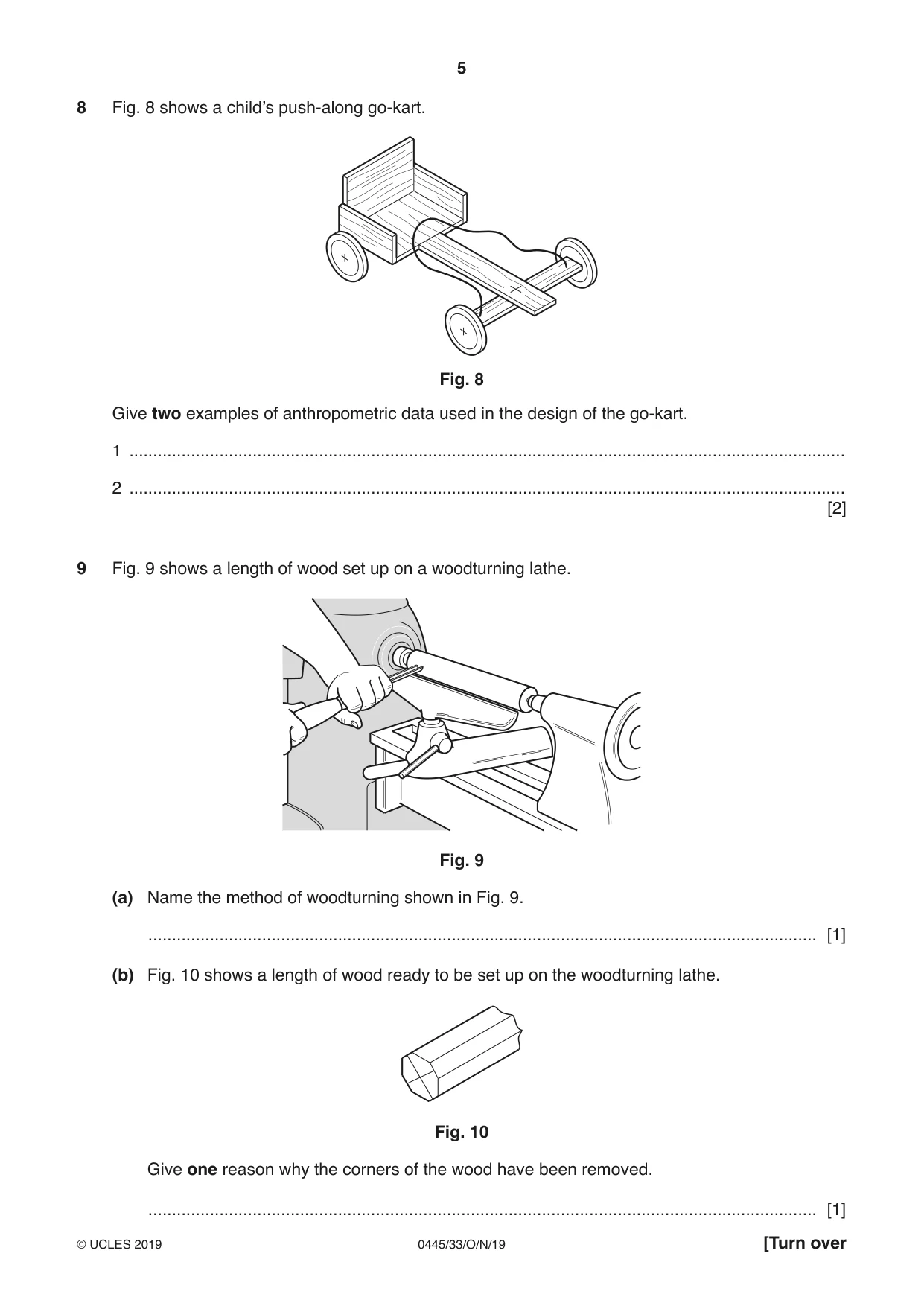
8 Fig. 8 shows a child’s push-along go-kart. Fig. 8 Give two examples of anthropometric data used in the design of the go-kart. 1 ....................................................................................................................................................... 2 ....................................................................................................................................................... [2]
Mark scheme: 8 Seat and backrest: width of torso and height of torso. Distance from foot steering 2 dependent on leg length. Length of steering rope dependent on arm length/reach 2×1
Q9 · A length of wood set up on a woodturning lathe
9 Fig. 9 shows a length of wood set up on a woodturning lathe. Fig. 9 (a) Name the method of woodturning shown in Fig. 9. ............................................................................................................................................. [1] (b) Fig. 10 shows a length of wood ready to be set up on the woodturning lathe. Fig. 10 Give one reason why the corners of the wood have been removed. ............................................................................................................................................. [1]
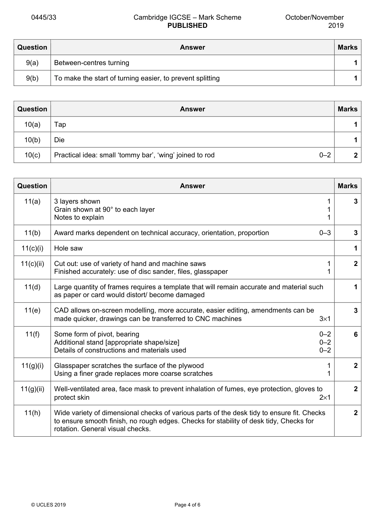
Mark scheme: 9(a) Between-centres turning 1 9(b) To make the start of turning easier, to prevent splitting 1
Q10 · An incomplete metal bracket used to support a net on a table-tennis table
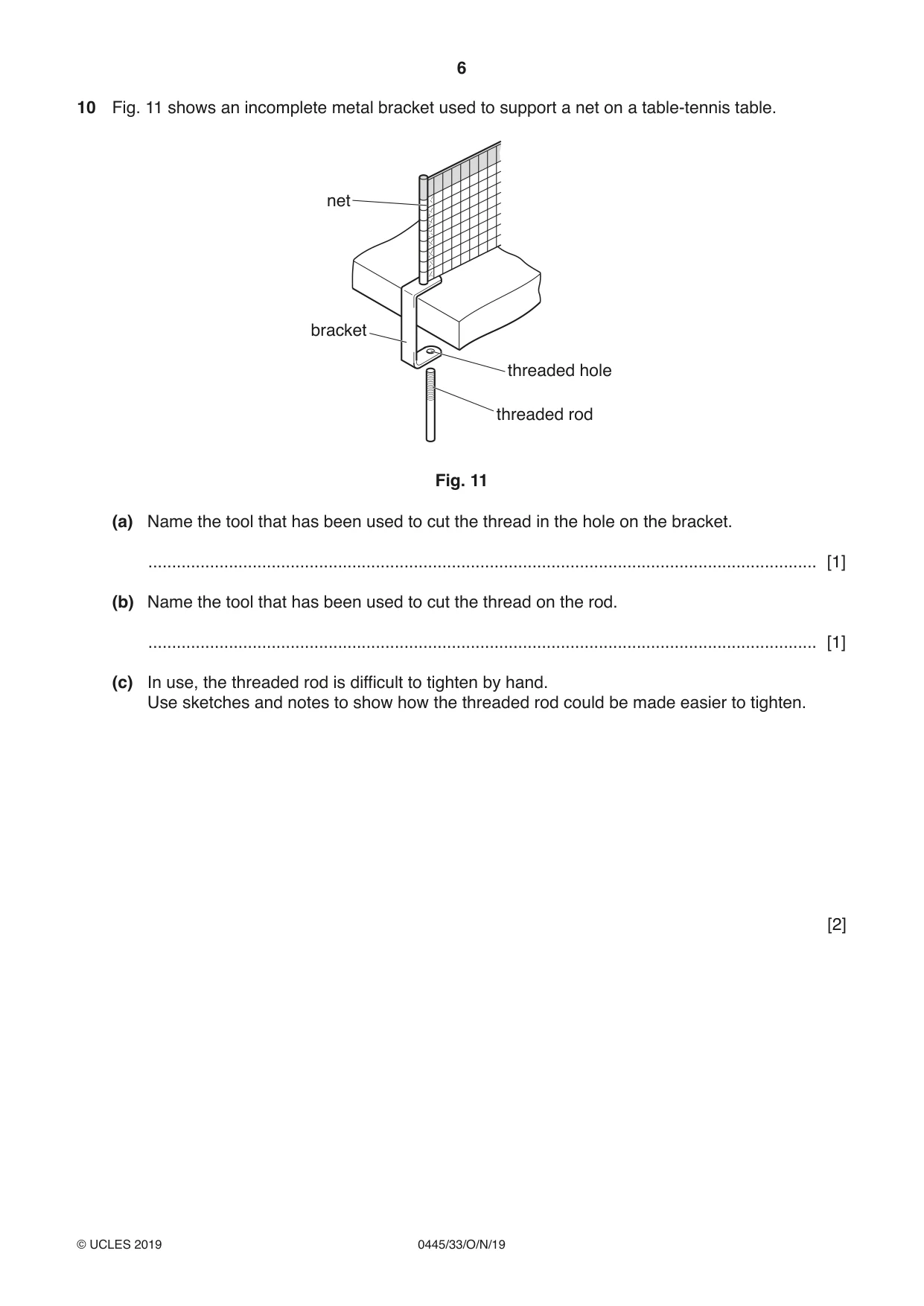
10 Fig. 11 shows an incomplete metal bracket used to support a net on a table-tennis table. net bracket threaded hole threaded rod Fig. 11 (a) Name the tool that has been used to cut the thread in the hole on the bracket. ............................................................................................................................................. [1] (b) Name the tool that has been used to cut the thread on the rod. ............................................................................................................................................. [1] (c) In use, the threaded rod is difficult to tighten by hand. Use sketches and notes to show how the threaded rod could be made easier to tighten. [2]
Mark scheme: 10(a) Tap 1 10(b) Die 1 10(c) Practical idea: small ‘tommy bar’, ‘wing’ joined to rod 0–2 2
Q11 · A desk tidy made from 4 mm thick plywood
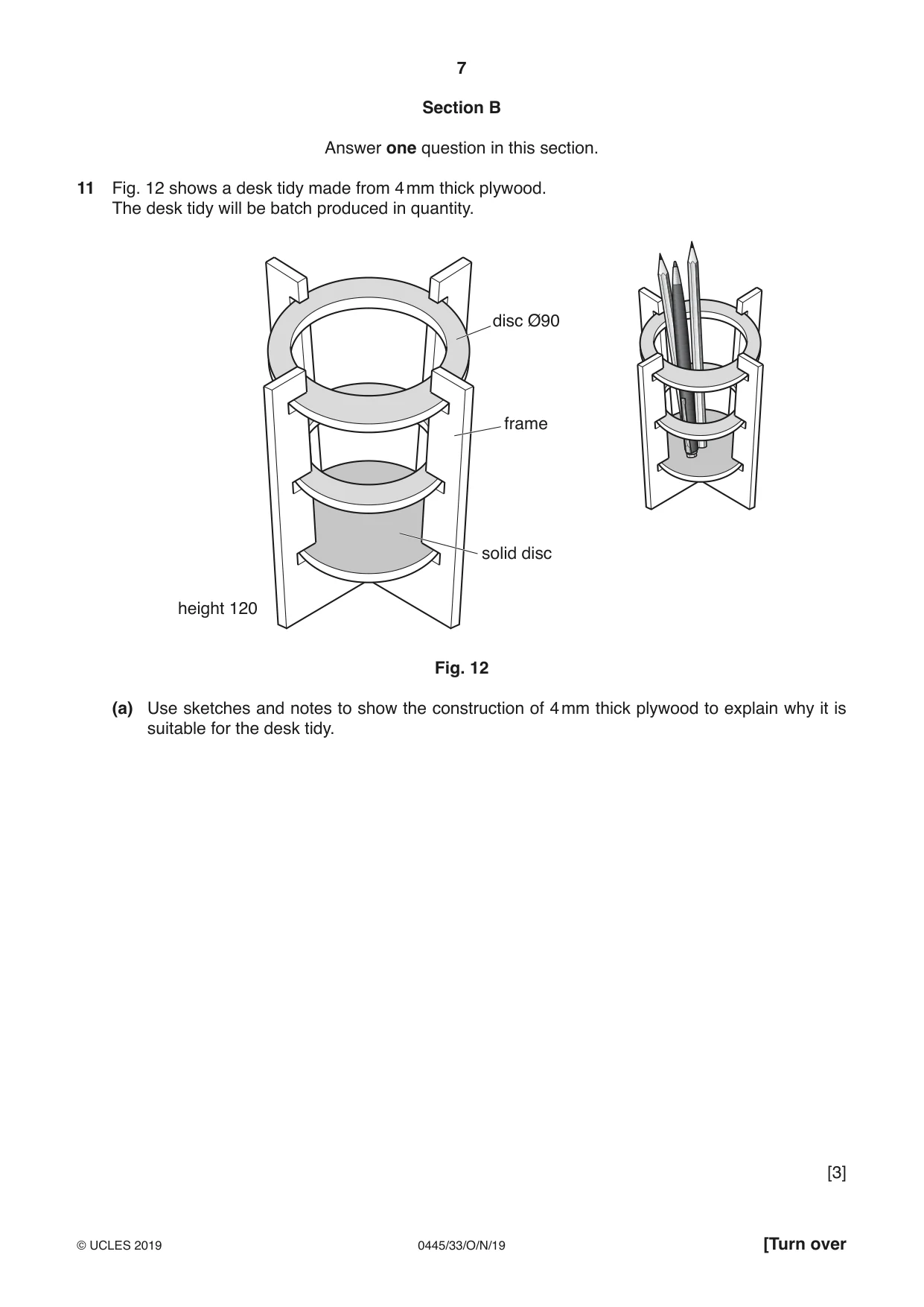
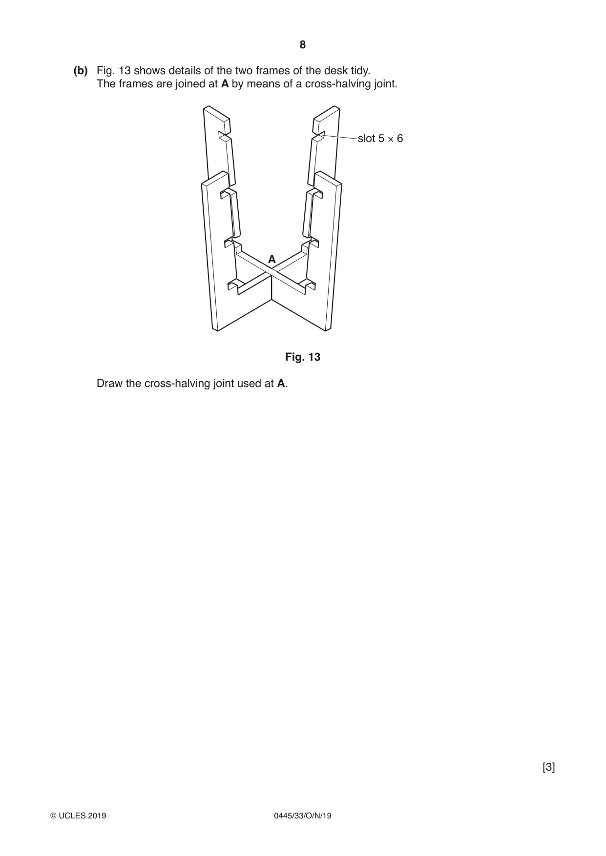
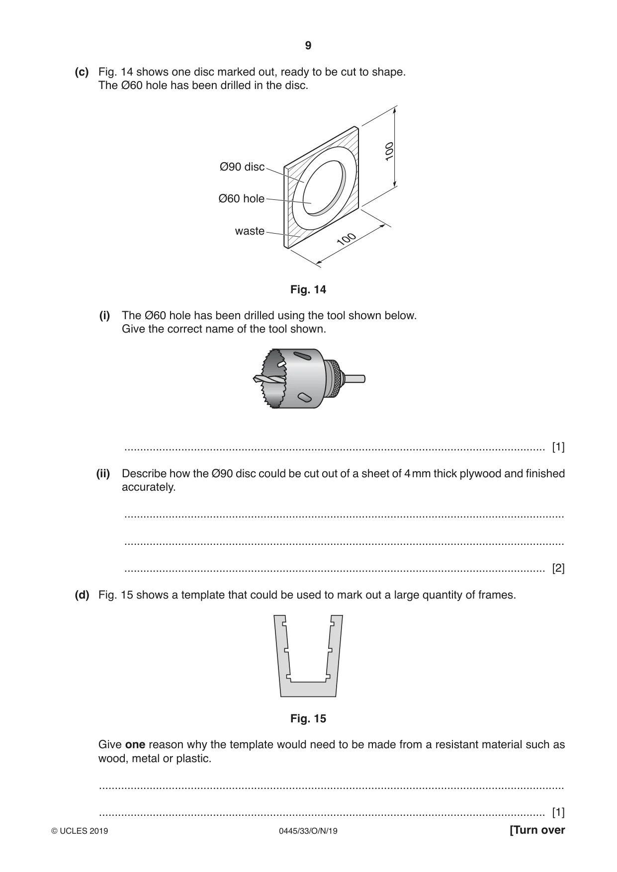
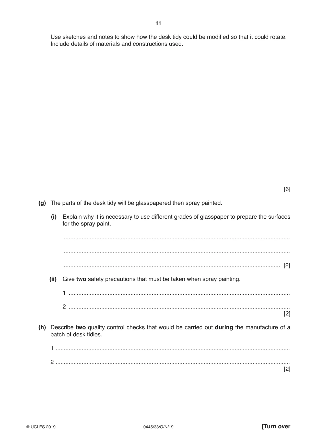
11 Fig. 12 shows a desk tidy made from 4 mm thick plywood. The desk tidy will be batch produced in quantity. disc Ø90 frame solid disc height 120 Fig. 12 (a) Use sketches and notes to show the construction of 4 mm thick plywood to explain why it is suitable for the desk tidy. [3] (b) Fig. 13 shows details of the two frames of the desk tidy. The frames are joined at A by means of a cross-halving joint. slot 5 × 6 A Fig. 13 Draw the cross-halving joint used at A. [3] (c) Fig. 14 shows one disc marked out, ready to be cut to shape. The Ø60 hole has been drilled in the disc. 100 Ø90 disc Ø60 hole waste 100 Fig. 14 (i) The Ø60 hole has been drilled using the tool shown below. Give the correct name of the tool shown. ..................................................................................................................................... [1] (ii) Describe how the Ø90 disc could be cut out of a sheet of 4 mm thick plywood and finished accurately. ........................................................................................................................................... ........................................................................................................................................... ..................................................................................................................................... [2] (d) Fig. 15 shows a template that could be used to mark out a large quantity of frames. Fig. 15 Give one reason why the template would need to be made from a resistant material such as wood, metal or plastic. ................................................................................................................................................... ............................................................................................................................................. [1] (e) The desk tidy could be designed using CAD. Give three advantages, other than speed, of using CAD rather than traditional drawing methods to design the desk tidy. 1 ................................................................................................................................................ 2 ................................................................................................................................................ 3 ................................................................................................................................................ [3] (f) The desk tidy needs to be modified so that it can rotate as shown in Fig. 16. desk tidy rotates disc Ø90 frame solid disc height 120 Fig. 16 Use sketches and notes to show how the desk tidy could be modified so that it could rotate. Include details of materials and constructions used. [6] (g) The parts of the desk tidy will be glasspapered then spray painted. (i) Explain why it is necessary to use different grades of glasspaper to prepare the surfaces for the spray paint. ........................................................................................................................................... ........................................................................................................................................... ..................................................................................................................................... [2] (ii) Give two safety precautions that must be taken when spray painting. 1 ........................................................................................................................................ 2 ........................................................................................................................................ [2] (h) Describe two quality control checks that would be carried out during the manufacture of a batch of desk tidies. 1 ................................................................................................................................................ 2 ................................................................................................................................................ [2]
Mark scheme: 11(a) 3 layers shown 1 3 Grain shown at 90° to each layer 1 Notes to explain 1 11(b) Award marks dependent on technical accuracy, orientation, proportion 0–3 3 11(c)(i) Hole saw 1 11(c)(ii) Cut out: use of variety of hand and machine saws 1 2 Finished accurately: use of disc sander, files, glasspaper 1 11(d) Large quantity of frames requires a template that will remain accurate and material such 1 as paper or card would distort/ become damaged 11(e) CAD allows on-screen modelling, more accurate, easier editing, amendments can be 3 made quicker, drawings can be transferred to CNC machines 3×1 11(f) Some form of pivot, bearing 0–2 6 Additional stand [appropriate shape/size] 0–2 Details of constructions and materials used 0–2 11(g)(i) Glasspaper scratches the surface of the plywood 1 2 Using a finer grade replaces more coarse scratches 1 11(g)(ii) Well-ventilated area, face mask to prevent inhalation of fumes, eye protection, gloves to 2 protect skin 2×1 11(h) Wide variety of dimensional checks of various parts of the desk tidy to ensure fit. Checks 2 to ensure smooth finish, no rough edges. Checks for stability of desk tidy, Checks for rotation. General visual checks.
Q12 · A basic design for a toothbrush holder made from 4 mm thick acrylic
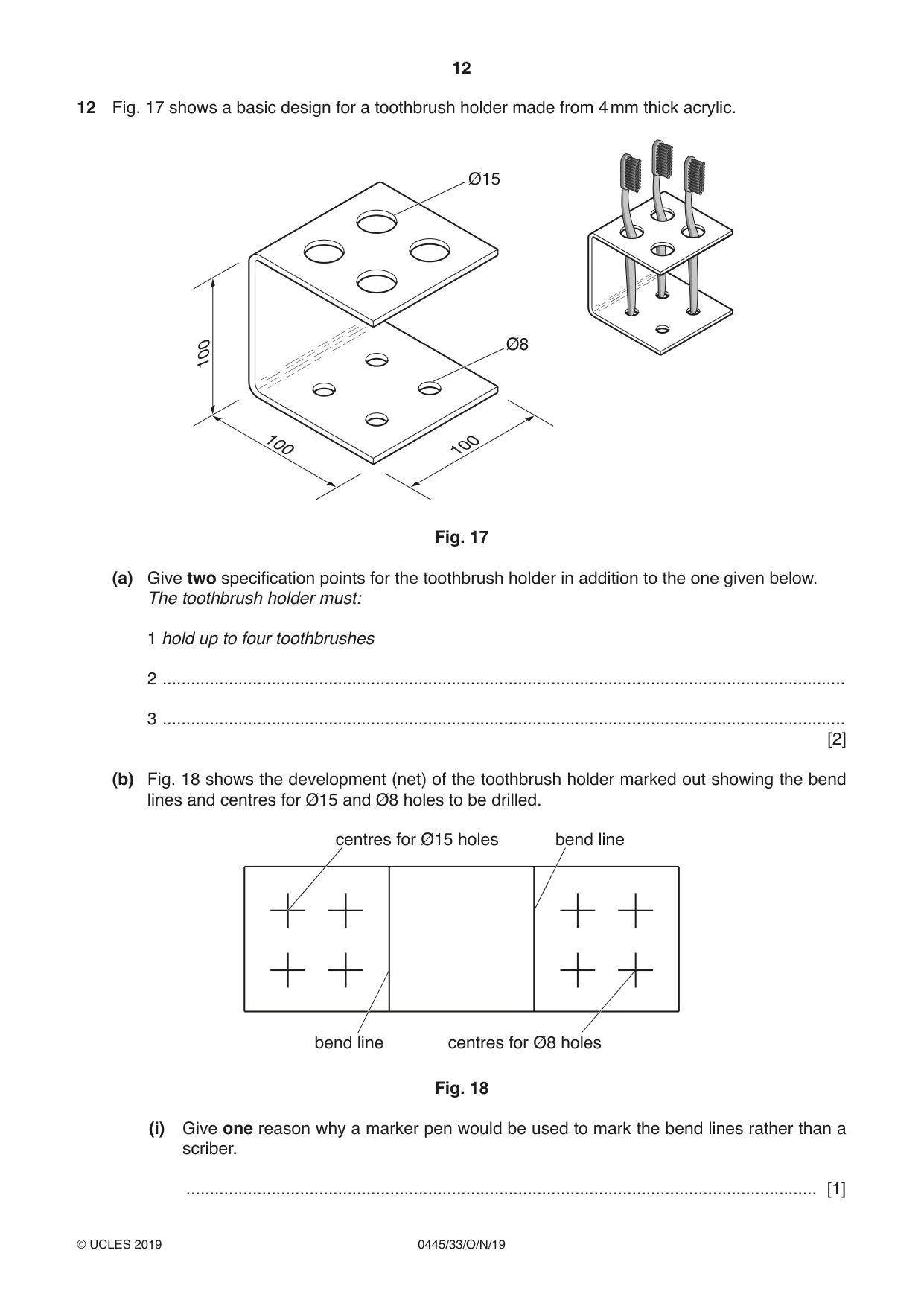
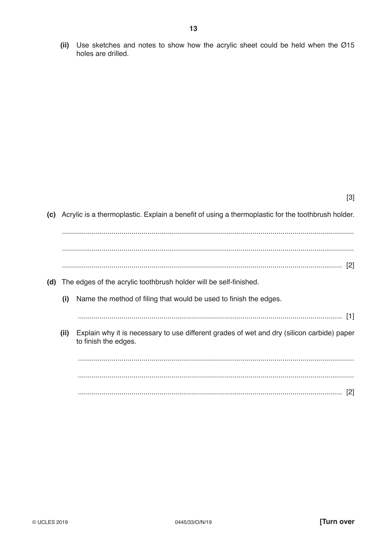
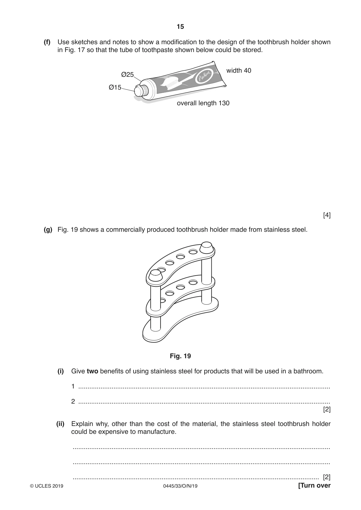
12 Fig. 17 shows a basic design for a toothbrush holder made from 4 mm thick acrylic. Ø15 100 Ø8 100 100 Fig. 17 (a) Give two specification points for the toothbrush holder in addition to the one given below. The toothbrush holder must: 1 hold up to four toothbrushes 2 ................................................................................................................................................ 3 ................................................................................................................................................ [2] (b) Fig. 18 shows the development (net) of the toothbrush holder marked out showing the bend lines and centres for Ø15 and Ø8 holes to be drilled. centres for Ø15 holes bend line bend line centres for Ø8 holes Fig. 18 (i) Give one reason why a marker pen would be used to mark the bend lines rather than a scriber. ..................................................................................................................................... [1] (ii) Use sketches and notes to show how the acrylic sheet could be held when the Ø15 holes are drilled. [3] (c) Acrylic is a thermoplastic. Explain a benefit of using a thermoplastic for the toothbrush holder. ................................................................................................................................................... ................................................................................................................................................... ............................................................................................................................................. [2] (d) The edges of the acrylic toothbrush holder will be self-finished. (i) Name the method of filing that would be used to finish the edges. ..................................................................................................................................... [1] (ii) Explain why it is necessary to use different grades of wet and dry (silicon carbide) paper to finish the edges. ........................................................................................................................................... ........................................................................................................................................... ..................................................................................................................................... [2] (e) A batch of 40 toothbrush holders is to be made in a school workshop. Use sketches and notes to show: (i) a design for a drilling jig that could be used to speed up production [3] (ii) how the acrylic shape could be bent accurately to the required shape. [3] (f) Use sketches and notes to show a modification to the design of the toothbrush holder shown in Fig. 17 so that the tube of toothpaste shown below could be stored. width 40 Ø25 Ø15 overall length 130 [4] (g) Fig. 19 shows a commercially produced toothbrush holder made from stainless steel. Fig. 19 (i) Give two benefits of using stainless steel for products that will be used in a bathroom. 1 ........................................................................................................................................ 2 ........................................................................................................................................ [2] (ii) Explain why, other than the cost of the material, the stainless steel toothbrush holder could be expensive to manufacture. ........................................................................................................................................... ...........................................................................................................................................
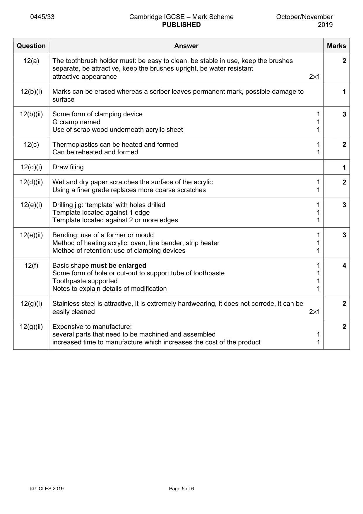
Mark scheme: 12(a) The toothbrush holder must: be easy to clean, be stable in use, keep the brushes 2 separate, be attractive, keep the brushes upright, be water resistant attractive appearance 2×1 12(b)(i) Marks can be erased whereas a scriber leaves permanent mark, possible damage to 1 surface 12(b)(ii) Some form of clamping device 1 3 G cramp named 1 Use of scrap wood underneath acrylic sheet 1 12(c) Thermoplastics can be heated and formed 1 2 Can be reheated and formed 1 12(d)(i) Draw filing 1 12(d)(ii) Wet and dry paper scratches the surface of the acrylic 1 2 Using a finer grade replaces more coarse scratches 1 12(e)(i) Drilling jig: ‘template’ with holes drilled 1 3 Template located against 1 edge 1 Template located against 2 or more edges 1 12(e)(ii) Bending: use of a former or mould 1 3 Method of heating acrylic; oven, line bender, strip heater 1 Method of retention: use of clamping devices 1 12(f) Basic shape must be enlarged 1 4 Some form of hole or cut-out to support tube of toothpaste 1 Toothpaste supported 1 Notes to explain details of modification 1 12(g)(i) Stainless steel is attractive, it is extremely hardwearing, it does not corrode, it can be 2 easily cleaned 2×1 12(g)(ii) Expensive to manufacture: 2 several parts that need to be machined and assembled 1 increased time to manufacture which increases the cost of the product 1
Q13 · A wall-mounted cycle rack made from 19 mm thick manufactured board
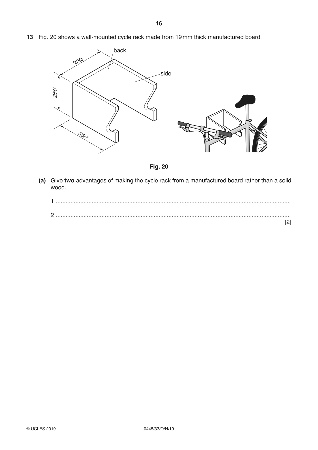
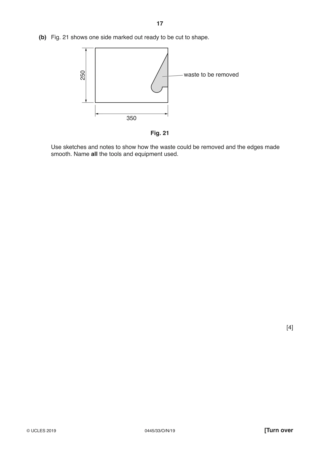
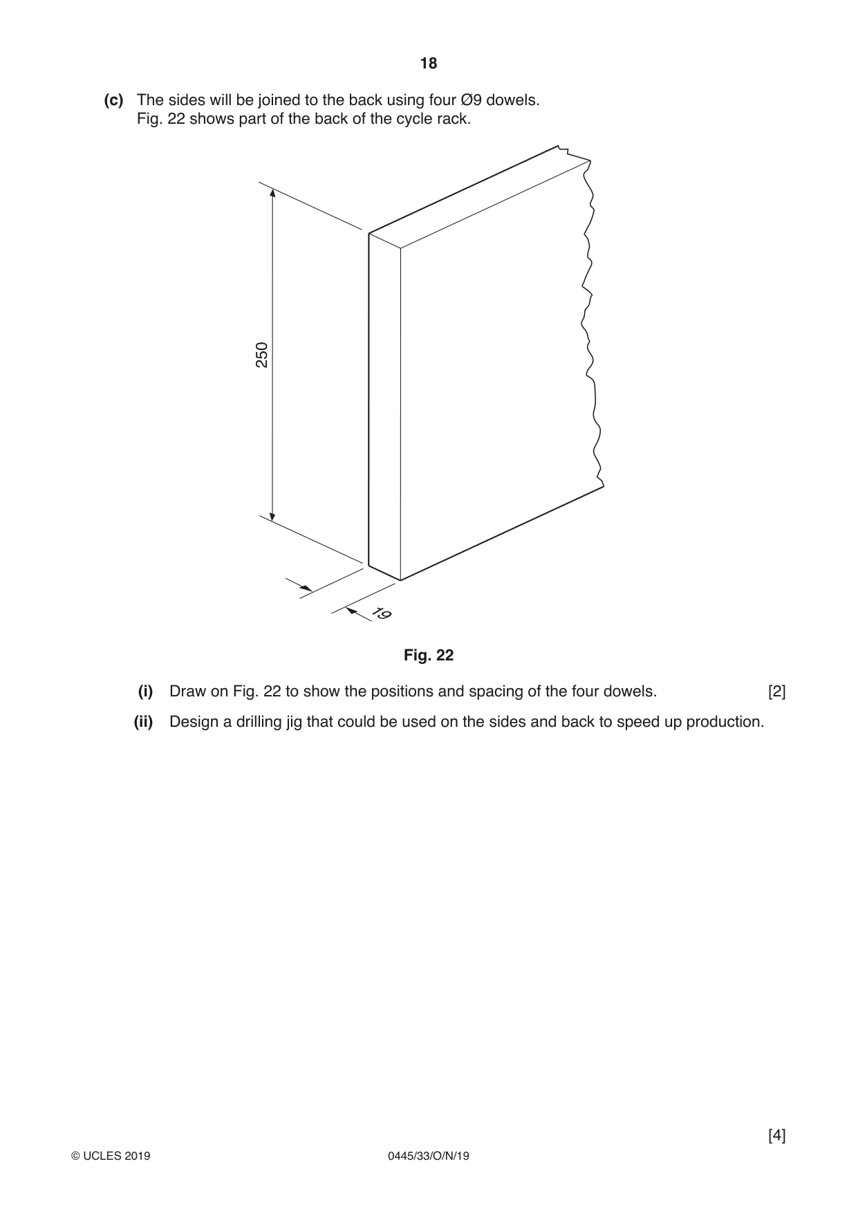
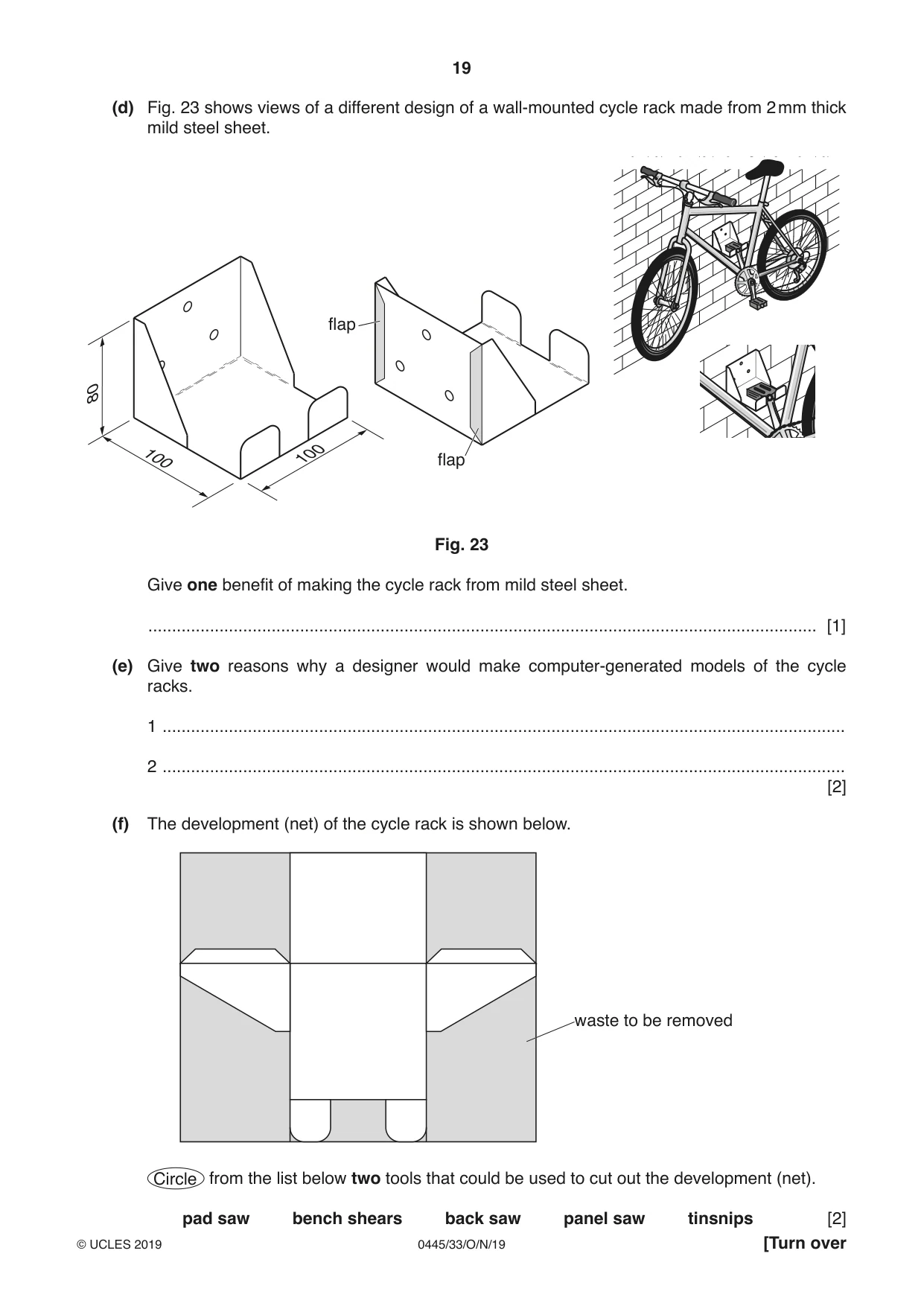
13 Fig. 20 shows a wall-mounted cycle rack made from 19 mm thick manufactured board. back 330 side 250 350 de Fig. 20 (a) Give two advantages of making the cycle rack from a manufactured board rather than a solid wood. 1 ................................................................................................................................................ 2 ................................................................................................................................................ [2] (b) Fig. 21 shows one side marked out ready to be cut to shape. 250 waste to be removed 350 Fig. 21 Use sketches and notes to show how the waste could be removed and the edges made smooth. Name all the tools and equipment used. [4] (c) The sides will be joined to the back using four Ø9 dowels. Fig. 22 shows part of the back of the cycle rack. 250 19 Fig. 22 (i) Draw on Fig. 22 to show the positions and spacing of the four dowels. [2] (ii) Design a drilling jig that could be used on the sides and back to speed up production.
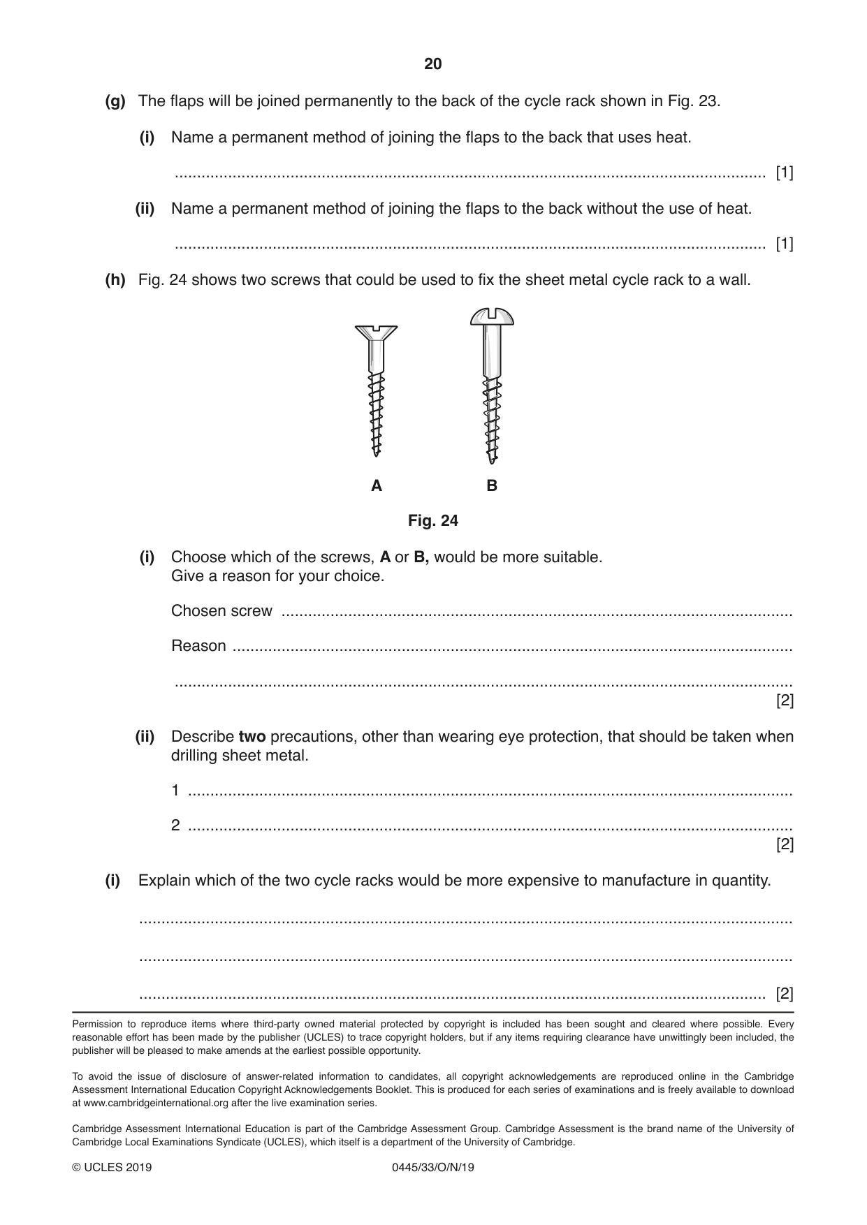
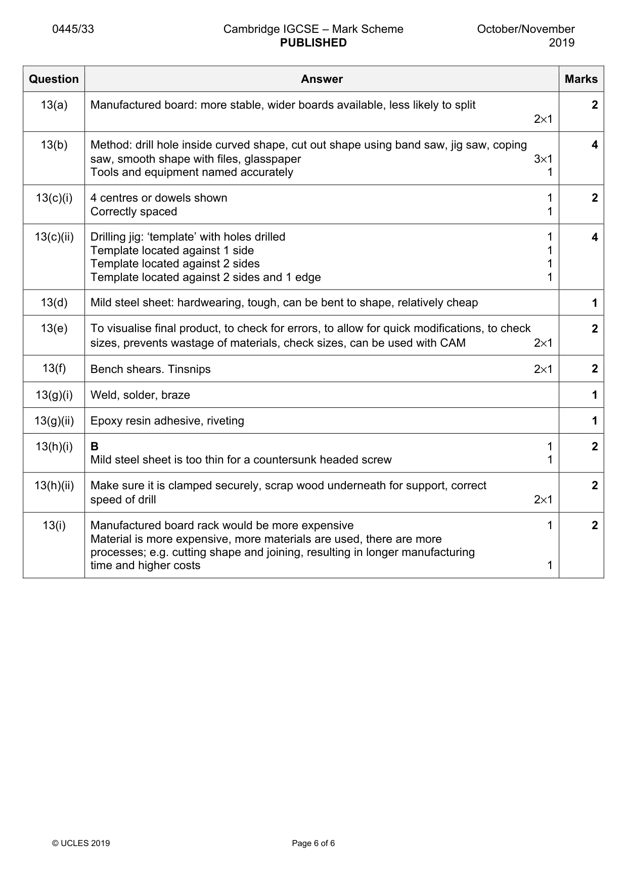
Mark scheme: 13(a) Manufactured board: more stable, wider boards available, less likely to split 2 2×1 13(b) Method: drill hole inside curved shape, cut out shape using band saw, jig saw, coping 4 saw, smooth shape with files, glasspaper 3×1 Tools and equipment named accurately 1 13(c)(i) 4 centres or dowels shown 1 2 Correctly spaced 1 13(c)(ii) Drilling jig: ‘template’ with holes drilled 1 4 Template located against 1 side 1 Template located against 2 sides 1 Template located against 2 sides and 1 edge 1 13(d) Mild steel sheet: hardwearing, tough, can be bent to shape, relatively cheap 1 13(e) To visualise final product, to check for errors, to allow for quick modifications, to check 2 sizes, prevents wastage of materials, check sizes, can be used with CAM 2×1 13(f) Bench shears. Tinsnips 2×1 2 13(g)(i) Weld, solder, braze 1 13(g)(ii) Epoxy resin adhesive, riveting 1 13(h)(i) B 1 2 Mild steel sheet is too thin for a countersunk headed screw 1 13(h)(ii) Make sure it is clamped securely, scrap wood underneath for support, correct 2 speed of drill 2×1 13(i) Manufactured board rack would be more expensive 1 2 Material is more expensive, more materials are used, there are more processes; e.g. cutting shape and joining, resulting in longer manufacturing time and higher costs 1
What was in this paper
The subtopics covered by these 13 questions, and how many questions each got. Open one in a new tab to see every Cambridge question on it.
What you needed in this session
Cambridge’s own grade thresholds for 2019 Oct/Nov, Paper 3 · Variant 3. A higher threshold means an easier paper — the bar moves with how the cohort did.